| Title | Size | Downloads |
|---|---|---|
| H3C SR6600 Routers DVPN Configuration Example-book.pdf | 1.05 MB |
- Table of Contents
H3C SR6600 Routers DVPN Configuration Example
Keywords: DVPN, VPN, VAM, AAA, IPsec, GRE
Abstract: This document describes the DVPN configuration example for the H3C SR6600 Routers Series.
Acronyms:
|
Acronym |
Full spelling |
|
AAA |
Authentication Accounting Authorization |
|
DVPN |
Dynamic Virtual Private Network |
|
GRE |
Generic Routing Encapsulation |
|
IPsec |
IP Security |
|
VAM |
VPN Address Management |
|
VPN |
Virtual Private Network |
Contents
Feature overview
Nowadays, enterprises usually establish VPNs to connect their branches across the public network. However, branches of an enterprise usually use dynamically assigned IP addresses to access the public network, and a branch cannot know the public IP addresses of other branches in advance. This makes it difficult for establishing VPNs. The DVPN solution is intended to address this issue.
Application scenarios
DVPN is a type of Layer 3 VPN. Encapsulation on the public network is regarded as the encapsulation at the data link layer of the private network.
DVPN supports AAA identity authentication of VAM clients on the VAM server.
DVPN extends a tunnel interface. It supports point-to-multipoint tunnels by allowing for multiple point-to-point tunnels on one tunnel interface. To establish point-to-multipoint tunnels, on the hub end, you perform the tunnel configuration for only once, instead of doing so for each tunnel, greatly reducing the configuration workload.
DVPN tunnels use IPsec to protect all the forwarded data, providing data privacy, authenticity, and replay protection.
A DVPN mode supports multiple VPN domains. This improves network device utility and networking flexibility, and reduces customers’ investment in devices.
DVPN supports backup for key nodes, satisfying the requirements of carriers and enterprises for high network availability.
Configuration guidelines
Note the following when you configure DVPN:
· If you specify a source interface for a tunnel interface, the tunnel interface takes the primary IP address of the source interface as the tunnel’s source address.
· To configure multiple DVPN tunnels that use GRE encapsulation, you must configure a unique source address or source interface for each tunnel.
· In the same VPN domain, you must ensure that the private addresses of all tunnel interfaces belong to the same subnet.
DVPN configuration example
Network requirement
|
|
NOTE: In this example, the routing protocol is OSPF. In this case, The DR priority of the hub must be higher than that of a spoke. H3C recommends that you set the DR priority to 0 for spokes, so that the spokes do not participate in DR/BDR election. |
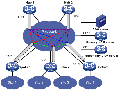
In the full mesh network, the primary VAM server and the secondary VAM server manage and maintain information about each node. The AAA server takes charge of VAM client authentication and accounting. The two hubs back up each other and perform data forwarding and exchange routing information.
Establish a permanent tunnel between each hub-spoke pair.
Dynamically establish a tunnel between the spokes in the same VPN to exchange data.
Figure 1 Network diagram for a full-mesh DVPN
|
Device |
Interface |
IP address |
Device |
Interface |
IP address |
|
Hub 1 |
GE 1/1 |
192.168.1.1/24 |
Spoke 1 |
GE 1/1 |
192.168.1.3/24 |
|
|
Tunnel1 |
10.0.1.1/24 |
|
Tunnel1 |
10.0.1.3/24 |
|
Hub 2 |
GE 1/1 |
192.168.1.2/24 |
Spoke 2 |
GE 1/1 |
192.168.1.4/24 |
|
|
Tunnel1 |
10.0.1.2/24 |
|
Tunnel1 |
10.0.1.4/24 |
|
|
|
|
Spoke 3 |
GE 1/1 |
192.168.1.5/24 |
|
|
|
|
|
Tunnel1 |
10.0.1.5/24 |
|
AAA server |
|
192.168.1.11/24 |
|
|
|
|
Primary VAM server |
GE 1/1 |
192.168.1.22/24 |
|
|
|
|
Secondary VAM server |
GE 1/1 |
192.168.1.33//24 |
|
|
|
Configuration considerations
Perform the following configuration to configure DVPN:
· Configure AAA and VAM Server on the DVPN servers.
· Configure VAM Client, IPsec profile, DVPN tunnel parameters, and routing on the DVPN clients.
Software version used
[SR6600] display version
H3C Comware Platform Software
Comware Software, Version 5.20, Feature 2602P02
Copyright (c) 2004-2011 Hangzhou H3C Tech. Co., Ltd. All rights reserved.
H3C SR6602 uptime is 0 week, 4 days, 5 hours, 24 minutes
CPU type: RMI XLR732 1000MHz
2048M bytes DDR2 SDRAM Memory
4M bytes Flash Memory
PCB Version: Ver.B
Logic Version: 2.0
Basic BootWare Version: 1.16
Extend BootWare Version: 1.32
[FIXED PORT] CON (Hardware)Ver.B, (Driver)1.0, (Cpld)2.0
[FIXED PORT] AUX (Hardware)Ver.B, (Driver)1.0, (Cpld)2.0
[FIXED PORT] GE 0/0 (Hardware)Ver.B, (Driver)1.0, (Cpld)1.0
[FIXED PORT] GE 0/1 (Hardware)Ver.B, (Driver)1.0, (Cpld)1.0
[FIXED PORT] GE 0/2 (Hardware)Ver.B, (Driver)1.0, (Cpld)1.0
[FIXED PORT] GE 0/3 (Hardware)Ver.B, (Driver)1.0, (Cpld)1.0
[SLOT 1] HIM-8GBE (Hardware)Ver.B, (Driver)1.0, (Cpld)2.0
[SLOT 2] HIM-8GBE (Hardware)Ver.B, (Driver)1.0, (Cpld)2.0
Configuration procedures
Configuring the routers
1. Configure the primary VAM server.
· Configure IP addresses for the interfaces. (Details not shown)
· Configure AAA.
<PrimaryServer> system-view
# Configure RADIUS scheme radsun.
[PrimaryServer] radius scheme radsun
[PrimaryServer-radius-radsun] primary authentication 192.168.1.11 1812
[PrimaryServer-radius-radsun] primary accounting 192.168.1.11 1813
[PrimaryServer-radius-radsun] key authentication expert
[PrimaryServer-radius-radsun] key accounting expert
[PrimaryServer-radius-radsun] server-type extended
[PrimaryServer-radius-radsun] user-name-format without-domain
[PrimaryServer-radius-radsun] quit
# Create ISP domain domain1 and specify the AAA methods for the ISP domain.
[PrimaryServer] domain domain1
[PrimaryServer-isp-domain1] authentication dvpn radius-scheme radsun
[PrimaryServer-isp-domain1] authorization dvpn radius-scheme radsun
[PrimaryServer-isp-domain1] accounting dvpn radius-scheme radsun
[PrimaryServer-isp-domain1] quit
[PrimaryServer] domain default enable domain1
· Configure the VAM server function.
# Specify a listening IP address for the VAM server.
[PrimaryServer] vam server ip-address 192.168.1.22
# Create VPN domain 1.
[PrimaryServer] vam server vpn 1
# Configure the pre-shared key as 123.
[PrimaryServer-vam-server-vpn-1] pre-shared-key simple 123
# Use CHAP to authenticate VAM clients.
[PrimaryServer-vam-server-vpn-1] authentication-method chap
# Specify IP addresses for the hubs in VPN domain 1.
[PrimaryServer-vam-server-vpn-1] hub private-ip 10.0.1.1
[PrimaryServer-vam-server-vpn-1] hub private-ip 10.0.1.2
[PrimaryServer-vam-server-vpn-1] quit
# Enable the VAM server function of all VPN domains.
[PrimaryServer] vam server enable all
2. Configure the secondary VAM server.
The secondary VAM server has the same configuration as the primary VAM server, except for the listening IP address.
3. Configure hub 1.
· Configure IP addresses for the interfaces. (Details not shown)
· Configure the VAM client function.
<Hub1> system-view
# Create VAM client dvpn1hub1 for VPN domain 1.
[Hub1] vam client name dvpn1hub1
[Hub1-vam-client-name-dvpn1hub1] vpn 1
# Specify the IP addresses of the primary and secondary VAM servers and set the pre-shared key for the VAM client.
[Hub1-vam-client-name-dvpn1hub1] server primary ip-address 192.168.1.22
[Hub1-vam-client-name-dvpn1hub1] server secondary ip-address 192.168.1.33
[Hub1-vam-client-name-dvpn1hub1] pre-shared-key simple 123
# Configure a local user, and specify the username as dvpn_user and password as dvpn_user.
[Hub1-vam-client-name-dvpn1hub1] user dvpn_user password simple dvpn_user
[Hub1-vam-client-name-dvpn1hub1] client enable
[Hub1-vam-client-name-dvpn1hub1] quit
· Configure an IPsec profile.
# Configure an IPsec proposal.
[Hub1] ipsec proposal vam
[Hub1-ipsec-proposal-vam] encapsulation-mode tunnel
[Hub1-ipsec-proposal-vam] transform esp
[Hub1-ipsec-proposal-vam] esp encryption-algorithm des
[Hub1-ipsec-proposal-vam] esp authentication-algorithm sha1
[Hub1-ipsec-proposal-vam] quit
# Configure an IKE peer.
[Hub1] ike peer vam
[Hub1-ike-peer-vam] pre-shared-key abcde
[Hub1-ike-peer-vam] quit
# Configure an IPsec profile.
[Hub1] ipsec profile vamp
[Hub1-ipsec-profile-vamp] proposal vam
[Hub1-ipsec-profile-vamp] ike-peer vam
[Hub1-ipsec-profile-vamp] sa duration time-based 600
[Hub1-ipsec-profile-vamp] pfs dh-group2
[Hub1-ipsec-profile-vamp] quit
· Configure a DVPN tunnel.
# Configure tunnel interface Tunnel1 for VPN domain 1, and UDP as the tunnel encapsulation protocol.
[Hub1] interface tunnel 1
[Hub1-Tunnel1] tunnel-protocol dvpn udp
[Hub1-Tunnel1] vam client dvpn1hub1
[Hub1-Tunnel1] ip address 10.0.1.1 255.255.255.0
[Hub1-Tunnel1] source GigabitEthernet 1/1
[Hub1-Tunnel1] ospf network-type broadcast
[Hub1-Tunnel1] ipsec profile vamp
[Hub1-Tunnel1] quit
· Configure OSPF.
# Configure OSPF process 100 to advertise network 192.168.1.1.
[Hub1] ospf 100
[Hub1-ospf-100] area 0
[Hub1-ospf-100-area-0.0.0.0] network 192.168.1.1 0.0.0.255
[Hub1-ospf-100-area-0.0.0.0] quit
# Configure OSPF process 200 to advertise network 10.0.1.1.
[Hub1] ospf 200
[Hub1-ospf-200] area 0
[Hub1-ospf-200-area-0.0.0.0] network 10.0.1.1 0.0.0.255
[Hub1-ospf-200-area-0.0.0.0] quit
4. Configure hub 2.
· Configure IP addresses for the interfaces. (Details not shown)
· Configure the VAM client function.
<Hub2> system-view
# Create VAM client dvpn1hub2 for VPN domain 1.
[Hub2] vam client name dvpn1hub2
[Hub2-vam-client-name-dvpn1hub2] vpn 1
# Specify the IP addresses of the primary and secondary VAM servers and set the pre-shared key for the VAM client.
[Hub2-vam-client-name-dvpn1hub2] server primary ip-address 192.168.1.22
[Hub2-vam-client-name-dvpn1hub2] server secondary ip-address 192.168.1.33
[Hub2-vam-client-name-dvpn1hub2] pre-shared-key simple 123
# Configure a local user, and specify the username as dvpn_user and password as dvpn_user.
[Hub2-vam-client-name-dvpn1hub2] user dvpn_user password simple dvpn_user
[Hub2-vam-client-name-dvpn1hub2] client enable
[Hub2-vam-client-name-dvpn1hub2] quit
· Configure an IPsec profile.
# Configure an IPsec proposal.
[Hub2] ipsec proposal vam
[Hub2-ipsec-proposal-vam] encapsulation-mode tunnel
[Hub2-ipsec-proposal-vam] transform esp
[Hub2-ipsec-proposal-vam] esp encryption-algorithm des
[Hub2-ipsec-proposal-vam] esp authentication-algorithm sha1
[Hub2-ipsec-proposal-vam] quit
# Configure an IKE peer.
[Hub2] ike peer vam
[Hub2-ike-peer-vam] pre-shared-key abcde
[Hub2-ike-peer-vam] quit
# Configure an IPsec profile.
[Hub2] ipsec profile vamp
[Hub2-ipsec-profile-vamp] proposal vam
[Hub2-ipsec-profile-vamp] ike-peer vam
[Hub2-ipsec-profile-vamp] sa duration time-based 600
[Hub2-ipsec-profile-vamp] pfs dh-group2
[Hub2-ipsec-profile-vamp] quit
· Configure DVPN tunnels.
# Configure tunnel interface Tunnel1 for VPN domain 1, and UDP as the tunnel encapsulation protocol.
[Hub2] interface tunnel 1
[Hub2-Tunnel1] tunnel-protocol dvpn udp
[Hub2-Tunnel1] vam client dvpn1hub2
[Hub2-Tunnel1] ip address 10.0.1.2 255.255.255.0
[Hub2-Tunnel1] source GigabitEthernet 1/1
[Hub2-Tunnel1] ospf network-type broadcast
[Hub2-Tunnel1] ipsec profile vamp
[Hub2-Tunnel1] quit
· Configure OSPF.
# Configure OSPF process 100 to advertise network 192.168.1.2.
[Hub2] ospf 100
[Hub2-ospf-100] area 0
[Hub2-ospf-100-area-0.0.0.0] network 192.168.1.2 0.0.0.255
[Hub2-ospf-100-area-0.0.0.0] quit
# Configure OSPF process 200 to advertise network 10.0.1.2.
[Hub2] ospf 200
[Hub2-ospf-200] area 0
[Hub2-ospf-200-area-0.0.0.0] network 10.0.1.2 0.0.0.255
[Hub2-ospf-200-area-0.0.0.0] quit
5. Configure spoke 1.
· Configure IP addresses for the interfaces. (Details not shown)
· Configure the VAM client function.
<Spoke1> system-view
# Create VAM client dvpn1spoke1 for VPN domain 1.
[Spoke1] vam client name dvpn1spoke1
[Spoke1-vam-client-name-dvpn1spoke1] vpn 1
# Specify the IP addresses of the primary and secondary VAM servers and set the pre-shared key for the VAM client.
[Spoke1-vam-client-name-dvpn1spoke1] server primary ip-address 192.168.1.22
[Spoke1-vam-client-name-dvpn1spoke1] server secondary ip-address 192.168.1.33
[Spoke1-vam-client-name-dvpn1spoke1] pre-shared-key simple 123
# Configure a local user, and specify the username as dvpn_user and password as dvpn_user.
[Spoke1-vam-client-name-dvpn1spoke1] user dvpn_user password simple dvpn_user
[Spoke1-vam-client-name-dvpn1spoke1] client enable
[Spoke1-vam-client-name-dvpn1spoke1] quit
· Configure an IPsec profile.
# Configure an IPsec proposal.
[Spoke1] ipsec proposal vam
[Spoke1-ipsec-proposal-vam] encapsulation-mode tunnel
[Spoke1-ipsec-proposal-vam] transform esp
[Spoke1-ipsec-proposal-vam] esp encryption-algorithm des
[Spoke1-ipsec-proposal-vam] esp authentication-algorithm sha1
[Spoke1-ipsec-proposal-vam] quit
# Configure an IKE peer.
[Spoke1] ike peer vam
[Spoke1-ike-peer-vam] pre-shared-key abcde
[Spoke1-ike-peer-vam] quit
# Configure an IPsec profile.
[Spoke1] ipsec profile vamp
[Spoke1-ipsec-profile-vamp] proposal vam
[Spoke1-ipsec-profile-vamp] ike-peer vam
[Spoke1-ipsec-profile-vamp] sa duration time-based 600
[Spoke1-ipsec-profile-vamp] pfs dh-group2
[Spoke1-ipsec-profile-vamp] quit
· Configure a DVPN tunnel.
# Configure tunnel interface Tunnel1 for VPN domain 1, and UDP as the tunnel encapsulation protocol.
[Spoke1] interface tunnel 1
[Spoke1-Tunnel1] tunnel-protocol dvpn udp
[Spoke1-Tunnel1] vam client dvpn1spoke1
[Spoke1-Tunnel1] ip address 10.0.1.3 255.255.255.0
[Spoke1-Tunnel1] source GigabitEthernet 1/1
[Spoke1-Tunnel1] ospf network-type broadcast
[Spoke1-Tunnel1] ospf dr-priority 0
[Spoke1-Tunnel1] ipsec profile vamp
[Spoke1-Tunnel1] quit
· Configure OSPF.
# Configure OSPF process 100 to advertise network 192.168.1.3.
[Spoke1] ospf 100
[Spoke1-ospf-100] area 0
[Spoke1-ospf-100-area-0.0.0.0] network 192.168.1.3 0.0.0.255
[Spoke1-ospf-100-area-0.0.0.0] quit
# Configure OSPF process 200 to advertise network 10.0.1.3.
[Spoke1] ospf 200
[Spoke1-ospf-200] area 0
[Spoke1-ospf-200-area-0.0.0.0] network 10.0.1.3 0.0.0.255
6. Configure spoke 2.
· Configure IP addresses for the interfaces. (Details not shown)
· Configure the VAM client function.
<Spoke2> system-view
# Create VAM client dvpn1spoke2 for VPN domain 1.
[Spoke2] vam client name dvpn1spoke2
[Spoke2-vam-client-name-dvpn1spoke2] vpn 1
# Specify the IP addresses of the primary and secondary VAM servers and set the pre-shared key for the VAM client.
[Spoke2-vam-client-name-dvpn1spoke2] server primary ip-address 192.168.1.22
[Spoke2-vam-client-name-dvpn1spoke2] server secondary ip-address 192.168.1.33
[Spoke2-vam-client-name-dvpn1spoke2] pre-shared-key simple 123
# Configure a local user, and specify the username as dvpn_user and password as dvpn_user.
[Spoke2-vam-client-name-dvpn1spoke2] user dvpn_user password simple dvpn_user
[Spoke2-vam-client-name-dvpn1spoke2] client enable
[Spoke2-vam-client-name-dvpn1spoke2] quit
· Configure an IPsec profile.
# Configure an IPsec proposal.
[Spoke2] ipsec proposal vam
[Spoke2-ipsec-proposal-vam] encapsulation-mode tunnel
[Spoke2-ipsec-proposal-vam] transform esp
[Spoke2-ipsec-proposal-vam] esp encryption-algorithm des
[Spoke2-ipsec-proposal-vam] esp authentication-algorithm sha1
[Spoke2-ipsec-proposal-vam] quit
# Configure an IKE peer.
[Spoke2] ike peer vam
[Spoke2-ike-peer-vam] pre-shared-key abcde
[Spoke2-ike-peer-vam] quit
# Configure an IPsec profile.
[Spoke2] ipsec profile vamp
[Spoke2-ipsec-profile-vamp] proposal vam
[Spoke2-ipsec-profile-vamp] ike-peer vam
[Spoke2-ipsec-profile-vamp] sa duration time-based 600
[Spoke2-ipsec-profile-vamp] pfs dh-group2
[Spoke2-ipsec-profile-vamp] quit
· Configure a DVPN tunnel.
# Configure tunnel interface Tunnel1 for VPN domain 1, and UDP as the tunnel encapsulation protocol.
[Spoke2] interface tunnel 1
[Spoke2-Tunnel1] tunnel-protocol dvpn udp
[Spoke2-Tunnel1] vam client dvpn1spoke2
[Spoke2-Tunnel1] ip address 10.0.1.4 255.255.255.0
[Spoke2-Tunnel1] source GigabitEthernet 1/1
[Spoke2-Tunnel1] ospf network-type broadcast
[Spoke2-Tunnel1] ospf dr-priority 0
[Spoke2-Tunnel1] ipsec profile vamp
[Spoke2-Tunnel1] quit
· Configure OSPF.
# Configure OSPF process 100 to advertise network 192.168.1.4.
[Spoke2] ospf 100
[Spoke2-ospf-100] area 0
[Spoke2-ospf-100-area-0.0.0.0] network 192.168.1.4 0.0.0.255
[Spoke2-ospf-100-area-0.0.0.0] quit
# Configure OSPF process 200 to advertise network 10.0.1.4.
[Spoke2] ospf 200
[Spoke2-ospf-200] area 0
[Spoke2-ospf-200-area-0.0.0.0] network 10.0.1.4 0.0.0.255
[Spoke2-ospf-200-area-0.0.0.0] quit
7. Configure spoke 3.
· Configure IP addresses for the interfaces. (Details not shown)
· Configure the VAM client function.
<Spoke3> system-view
# Create VAM client dvpn1spoke3 for VPN domain 1.
[Spoke3] vam client name dvpn1spoke3
[Spoke3-vam-client-name-dvpn1spoke3] vpn 1
# Specify the IP addresses of the primary and secondary VAM servers and set the pre-shared key for the VAM client.
[Spoke3-vam-client-name-dvpn1spoke3] server primary ip-address 192.168.1.22
[Spoke3-vam-client-name-dvpn1spoke3] server secondary ip-address 192.168.1.33
[Spoke3-vam-client-name-dvpn1spoke3] pre-shared-key simple 123
# Configure a local user, and specify the username as dvpn_user and password as dvpn_user.
[Spoke3-vam-client-name-dvpn1spoke3] user dvpn_user password simple dvpn_user
[Spoke3-vam-client-name-dvpn1spoke3] client enable
[Spoke3-vam-client-name-dvpn1spoke3] quit
· Configure an IPsec profile.
# Configure an IPsec proposal.
[Spoke3] ipsec proposal vam
[Spoke3-ipsec-proposal-vam] encapsulation-mode tunnel
[Spoke3-ipsec-proposal-vam] transform esp
[Spoke3-ipsec-proposal-vam] esp encryption-algorithm des
[Spoke3-ipsec-proposal-vam] esp authentication-algorithm sha1
[Spoke3-ipsec-proposal-vam] quit
# Configure an IKE peer.
[Spoke3] ike peer vam
[Spoke3-ike-peer-vam] pre-shared-key abcde
[Spoke3-ike-peer-vam] quit
# Configure an IPsec profile.
[Spoke3] ipsec profile vamp
[Spoke3-ipsec-profile-vamp] proposal vam
[Spoke3-ipsec-profile-vamp] ike-peer vam
[Spoke3-ipsec-profile-vamp] sa duration time-based 600
[Spoke3-ipsec-profile-vamp] pfs dh-group2
[Spoke3-ipsec-profile-vamp] quit
· Configure DVPN tunnels.
# Configure tunnel interface Tunnel1 for VPN domain 1, and use UDP as the tunnel encapsulation protocol.
[Spoke3] interface tunnel 1
[Spoke3-Tunnel1] tunnel-protocol dvpn udp
[Spoke3-Tunnel1] vam client dvpn1spoke3
[Spoke3-Tunnel1] ip address 10.0.1.5 255.255.255.0
[Spoke3-Tunnel1] source GigabitEthernet 1/1
[Spoke3-Tunnel1] ospf network-type broadcast
[Spoke3-Tunnel1] ospf dr-priority 0
[Spoke3-Tunnel1] ipsec profile vamp
[Spoke3-Tunnel1] quit
· Configure OSPF.
# Configure OSPF process 100 to advertise network 192.168.1.5.
[Spoke3] ospf 100
[Spoke3-ospf-100] area 0
[Spoke3-ospf-100-area-0.0.0.0] network 192.168.1.5 0.0.0.255
[Spoke3-ospf-100-area-0.0.0.0] quit
# Configure OSPF process 200 to advertise network 10.0.1.5.
[Spoke3] ospf 200
[Spoke3-ospf-200] area 0
[Spoke3-ospf-200-area-0.0.0.0] network 10.0.1.5 0.0.0.255
Configure iMC
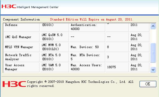
iMC version
Adding access devices
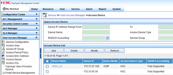
Configure the primary and secondary VAM servers as the access devices. The following steps take the primary VAM server as an example.
1. Log in to the iMC. Click the Service tab, and then select User Access Manager > Access Device from the navigation tree to enter the access device management page. Click Add.
2. Click Add Manually.
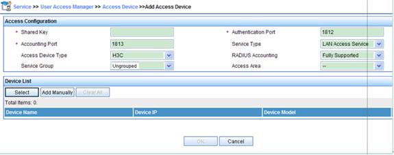
3. Type the access device’s IP address. To add only one access device, type the same IP address in the Start IP and End IP text boxes. Click OK.

4. Configure the access parameters as needed, and then click OK.
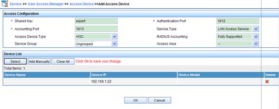
5. The access device is successfully added.

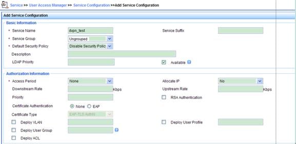
Configuring a service policy
1. Click the Service tab. Select User Access Manager > Service Configuration from the navigation tree. On the service configuration page, click Add.

2. In the Basic Information area, type dvpn_test in the Service Name text box.
Configuring a user account
1. Click the User tab. Select User Management > Add User from the navigation tree. Type dvpn_user for both User Name and Identity Number. Click OK.
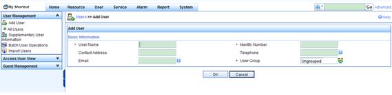
2. The user is added successfully.

3. Click Add Access User. Type dvpn_user for both the account name and password. Select the access service dvpn_test. Configure other parameters as needed.
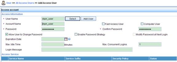
![]()
Verification
After the hub and spoke devices pass AAA authentication, you can see their registration information on the primary and secondary VAM servers.
# Display address mapping information about all VAM clients that have registered with the primary VAM server.
[PrimaryServer] display vam server address-map all
VPN name: 1
Total address-map number: 5
Private-ip Public-ip Type Holding time
10.0.1.1 192.168.1.1 Hub 0H 52M 7S
10.0.1.2 192.168.1.2 Hub 0H 47M 31S
10.0.1.3 192.168.1.3 Spoke 0H 28M 25S
10.0.1.4 192.168.1.4 Spoke 0H 19M 15S
10.0.1.5 192.168.1.5 Spoke 0H 19M 10S
# Display address mapping information about all VAM clients that have registered with the secondary VAM server.
[SecondaryServer] display vam server address-map all
VPN name: 1
Total address-map number: 5
Private-ip Public-ip Type Holding time
10.0.1.1 192.168.1.1 Hub 0H 55M 3S
10.0.1.2 192.168.1.2 Hub 0H 50M 30S
10.0.1.3 192.168.1.3 Spoke 0H 31M 24S
10.0.1.4 192.168.1.4 Spoke 0H 22M 15S
10.0.1.5 192.168.1.5 Spoke 0H 19M 10S
The output shows that hub 1, hub 2, spoke 1, spoke 2, and spoke 3 all have registered the address mapping information with the VAM servers.
# Display the DVPN tunnel information on hub 1.
[Hub1] display dvpn session all
Interface: Tunnel1 VPN name: 1 Total number: 4
Private IP: 10.0.1.2
Public IP: 192.168.1.2
Session type: Hub-Hub
State: SUCCESS
Holding time: 0h 1m 44s
Input: 101 packets, 100 data packets, 1 control packets
87 multicasts, 0 errors
Output: 106 packets, 99 data packets, 7 control packets
87 multicasts, 10 errors
Private IP: 10.0.1.3
Public IP: 192.168.1.3
Session type: Hub-Spoke
State: SUCCESS
Holding time: 0h 8m 7s
Input: 164 packets, 163 data packets, 1 control packets
154 multicasts, 0 errors
Output: 77 packets, 76 data packets, 1 control packets
155 multicasts, 0 errors
Private IP: 10.0.1.4
Public IP: 192.168.1.4
Session type: Hub-Spoke
State: SUCCESS
Holding time: 0h 27m 13s
Input: 174 packets, 167 data packets, 7 control packets
160 multicasts, 0 errors
Output: 172 packets, 171 data packets, 1 control packets
165 multicasts, 0 errors
Private IP: 10.0.1.5
Public IP: 192.168.1.5
Session type: Hub-Spoke
State: SUCCESS
Holding time: 0h 8m 7s
Input: 184 packets, 18 data packets, 1 control packets
104 multicasts, 0 errors
Output: 177 packets, 176 data packets, 1 control packets
105 multicasts, 0 errors
The output shows that in VPN 1, hub 1 has established a permanent tunnel with hub 2, spoke 1, spoke 2, and spoke 3, respectively.
# On spoke 2, ping the private address 10.0.1.5 of spoke 3.
[Spoke2] ping 10.0.1.5
PING 10.0.1.5: 56 data bytes, press CTRL_C to break
Reply from 10.0.1.5: bytes=56 Sequence=1 ttl=254 time=5 ms
Reply from 10.0.1.5: bytes=56 Sequence=2 ttl=254 time=5 ms
Reply from 10.0.1.5: bytes=56 Sequence=3 ttl=254 time=5 ms
Reply from 10.0.1.5: bytes=56 Sequence=4 ttl=254 time=4 ms
Reply from 10.0.1.5: bytes=56 Sequence=5 ttl=254 time=4 ms
--- 10.0.1.5 ping statistics ---
5 packet(s) transmitted
5 packet(s) received
0.00% packet loss
round-trip min/avg/max = 4/4/5 ms
The output shows that spoke 2 and spoke 3 can ping each other, which indicates that a tunnel is established dynamically between spoke 2 and spoke 3.
References
Protocols and standards
· RFC2401, Security Architecture for the Internet Protocol
· RFC2402, IP Authentication Header
· RFC2406, IP Encapsulating Security Payload
Related documentation
· H3C SR6600 Routers Configuration Guides-Release 2603
· H3C SR6600 Routers Command References-Release 2603
