- Table of Contents
- Related Documents
-
| Title | Size | Download |
|---|---|---|
| 03-WAN interface commands | 255.79 KB |
WAN interface commands
Common WAN interface commands
bandwidth
Use bandwidth to configure the expected bandwidth of an interface.
Use undo bandwidth to restore the default.
Syntax
bandwidth bandwidth-value
undo bandwidth
Default
The expected bandwidth (in kbps) is the interface baud rate divided by 1000.
Views
E1-F interface view
Serial interface/subinterface view
Predefined user roles
network-admin
mdc-admin
Parameters
bandwidth-value: Specifies the expected bandwidth in the range of 1 to 400000000 kbps.
Usage guidelines
The expected bandwidth is an informational parameter used only by higher-layer protocols for calculation. You cannot adjust the actual bandwidth of an interface by using this command.
Examples
# Set the expected bandwidth to 50 kbps for Serial 1/1/1.
<Sysname> system-view
[Sysname] interface serial 1/1/1
[Sysname-Serial1/1/1] bandwidth 50
default
Use default to restore the default settings for an interface.
Syntax
default
Views
CE1 interface/E1-F interface view
CT3 interface interface view
Serial interface/subinterface view
Predefined user roles
network-admin
mdc-admin
Usage guidelines
|
|
CAUTION: The default command might interrupt ongoing network services. Make sure you are fully aware of the impact of this command when you use it on a live network. |
This command might fail to restore the default settings for some commands for reasons such as command dependencies and system restrictions. You can use the display this command in interface view to check for these commands, and use their undo forms or follow the command reference to restore their respective default settings. If your restoration attempt still fails, follow the error message instructions to resolve the problem.
Examples
# Restore the default settings of Serial 1/1/1.
<Sysname> system-view
[Sysname] interface serial 1/1/1
[Sysname-Serial1/1/1] default
description
Use description to configure a description for an interface.
Use undo description to restore the default.
Syntax
description text
undo description
Default
Interface description uses the interface name Interface format, for example, Serial1/1/1 Interface.
Views
CE1 interface/E1-F interface view
CT3 interface interface view
Serial interface/subinterface view
Predefined user roles
network-admin
mdc-admin
Parameters
text: Specifies a description, a case-sensitive string of 1 to 255 characters.
Examples
# Configure the description of Serial 1/1/1 as router-interface.
<Sysname> system-view
[Sysname] interface serial 1/1/1
[Sysname-Serial1/1/1] description router-interface
shutdown
Use shutdown to shut down an interface.
Use undo shutdown to restore the default.
Syntax
shutdown
undo shutdown
Default
A WAN interface is up.
Views
CE1 interface/E1-F interface view
CT3 interface interface view
Serial interface/subinterface view
Predefined user roles
network-admin
mdc-admin
Examples
# Shut down Serial 1/1/1.
<Sysname> system-view
[Sysname] interface serial 1/1/1
[Sysname-Serial1/1/1] shutdown
timer-hold
Use timer-hold to set the keepalive interval.
Use undo timer-hold to restore the default.
Syntax
timer-hold seconds
undo timer-hold
Default
The keepalive interval is 10 seconds.
Views
E1-F interface view
Serial interface view
Predefined user roles
network-admin
mdc-admin
Parameters
seconds: Specifies the interval at which an interface sends keepalive packets. The value range is 0 to 32767 seconds.
Usage guidelines
On an interface encapsulated with PPP, FR, or HDLC, the data link layer sends keepalive packets at keepalive intervals to detect the availability of the remote end. The data link layer determines that the peer end is down if it does not receive a response after the maximum number of keepalive attempts have been made. The data link layer then reports the link down event to the upper-layer protocols.
To set the maximum number of keepalive attempts, use the timer-hold retry command.
On a slow link, increase the keepalive interval to prevent false shutdown of the interface. This situation might occur when keepalive packets are delayed because a large packet is being transmitted on the link.
Examples
# Set the keepalive interval to 15 seconds for Serial 1/1/1.
<Sysname> system-view
[Sysname] interface serial 1/1/1
[Sysname-Serial1/1/1] timer-hold 15
timer-hold retry
timer-hold retry
Use timer-hold retry to set the maximum number of keepalive attempts.
Use undo timer-hold retry to restore the default.
timer-hold retry retries
The maximum number of keepalive attempts is 5.
E1-F interface view
Serial interface view
network-admin
retries: Specifies the maximum number of keepalive attempts, in the range of 1 to 255.
The interface determines that the remote end is down if it does not receive a response after the maximum number of keepalive attempts have been made.
This command applies to interfaces encapsulated with PPP, FR, or HDLC. To set the keepalive interval, use the timer-hold command.
On a slow link, increase the maximum number of keepalive attempts to prevent false shutdown of the interface. This situation might occur when keepalive packets are delayed because a large packet is being transmitted on the link.
# Set the maximum number of keepalive attempts to 10 for Serial 1/1/1.
[Sysname] interface serial 1/1/1
[Sysname-Serial1/1/1] timer-hold retry 10
timer-hold
Synchronous serial interface commands
baudrate
Use baudrate to set the baud rate for a synchronous serial interface.
Use undo baudrate to restore the default.
Syntax
baudrate baudrate
undo baudrate
Default
The baud rate is 64000 bps on a synchronous serial interface.
Views
Synchronous serial interface view
Predefined user roles
network-admin
mdc-admin
Parameters
baudrate: Specifies a baud rate (in bps) for a serial interface. The baud rate range on a synchronous serial interface depends on the applied physical electric specifications.
· For V.24 DTE/DCE, available baud rates (in bps) are:
|
Baud rates |
|
|
|
1200 |
9600 |
56000 |
|
2400 |
19200 |
57600 |
|
4800 |
38400 |
64000 |
· For V.35 DCE/DCE and X.21 DTE/DCE, available baud rates (in bps) are:
|
Baud rates |
|
|
|
1200 |
57600 |
384000 |
|
2400 |
64000 |
512000 |
|
4800 |
72000 |
1024000 |
|
9600 |
115200 |
2048000 |
|
19200 |
128000 |
8192000 |
|
38400 |
192000 |
|
|
56000 |
256000 |
|
Usage guidelines
This command is supported only on serial interfaces of the MIM-2SAE, MIM-4SAE, and MIM-8SAE interface modules.
Take the physical electric specifications of the cable into consideration when you set the baud rate for a serial interface.
The baud rate used by a DCE-DTE pair is determined by the DCE.
Examples
# Set the baud rate to 115200 bps on DCE-side interface Serial 1/1/1.
<Sysname> system-view
[Sysname] interface serial 1/1/1
[Sysname-Serial1/1/1] baudrate 115200
Related commands
virtualbaudrate
code
Use code to configure the digital signal coding format on a synchronous serial interface.
Use undo code to restore the default.
Syntax
code { nrz | nrzi }
undo code
Default
The digital signal coding format is NRZ.
Views
Synchronous serial interface view
Predefined user roles
network-admin
mdc-admin
Parameters
nrz: Sets the digital signal coding format to nonreturn to zero (NRZ).
nrzi: Sets the digital signal coding format to nonreturn to zero inverted (NRZI).
Usage guidelines
This command is supported only on serial interfaces of the MIM-2SAE, MIM-4SAE, and MIM-8SAE interface modules.
Examples
# Set the digital signal coding format to NRZI on Serial 1/1/1.
<Sysname> system-view
[Sysname] interface serial 1/1/1
[Sysname-Serial1/1/1] code nrzi
crc
Use crc to set the CRC mode for a synchronous serial interface.
Use undo crc to restore the default.
Syntax
crc { 16 | 32 | none }
undo crc
Default
16-bit CRC is used.
Views
Synchronous serial interface view
Predefined user roles
network-admin
mdc-admin
Parameters
16: Specifies 16-bit CRC.
32: Specifies 32-bit CRC.
none: Disables CRC.
Examples
# Configure Serial 1/1/1 to use 32-bit CRC.
<Sysname> system-view
[Sysname] interface serial 1/1/1
[Sysname-Serial1/1/1] crc 32
clock
Use clock to set the clock selection mode for a synchronous serial interface.
Use undo clock to restore the default.
Syntax
clock { dteclk1 | dteclk2 | dteclk3 | dteclk4 | dteclk5 | dteclkauto }
undo clock
Default
The DTE-side clock is dteclk1.
Views
Synchronous serial interface view
Predefined user roles
network-admin
mdc-admin
Parameters
dteclk1: Sets the interface clock selection mode to DTE clock option 1.
dteclk2: Sets the interface clock selection mode to DTE clock option 2.
dteclk3: Sets the interface clock selection mode to DTE clock option 3.
dteclk4: Sets the interface clock selection mode to DTE clock option 4.
dteclk5: Sets the interface clock selection mode to DTE clock option 5. This keyword is not supported in the current software version.
dteclkauto: Sets the interface clock selection mode to DTE auto-negotiation.
Usage guidelines
A synchronous serial interface can operate as a DCE or DTE.
· As a DCE, the interface provides the DCEclk clock dteclk1 for the DTE.
· As a DTE, the interface accepts the clock provided by the DCE. Because transmitting and receiving clocks of synchronization devices are independent, the receiving clock of a DTE device can be either the transmitting or receiving clock of the DCE device. The transmitting clock of a DTE device can be either the transmitting or receiving clock of the DCE device. Therefore, five clock options are available for a DTE device.
In Figure 1, TxClk represents transmitting clock, and RxClk represents receiving clock.
Figure 1 Selecting a clock for a synchronous serial interface
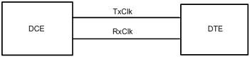
Table 1 describes the four clock selection options for a synchronous serial interface operating as a DTE. The clock preceding the equal sign (=) is the DTE clock, and the clock that follows the equal sign is the DCE clock.
Table 1 Clock options available for a synchronous serial interface operating as a DTE
|
Clock selection option |
Description |
|
DTEclk1 |
TxClk = TxClk, RxClk = RxClk. |
|
DTEclk2 |
TxClk = TxClk, RxClk = TxClk. |
|
DTEclk3 |
TxClk = RxClk, RxClk = TxClk. |
|
DTEclk4 |
TxClk = RxClk, RxClk = RxClk. |
|
DTEclk5 |
TxClk = Local, RxClk = Local. |
Examples
# Configure Serial 1/1/1 operating as a DTE to use clock selection option dteclk2.
<Sysname> system-view
[Sysname] interface serial 1/1/1
[Sysname-Serial1/1/1] clock dteclk2
detect dcd
Use detect dcd to enable data carrier detection (DCD) on a serial interface.
Use undo detect dcd to disable DCD on a serial interface.
Syntax
detect dcd
undo detect dcd
Default
DCD is enabled on a serial interface.
Views
Synchronous serial interface view
Predefined user roles
network-admin
mdc-admin
Usage guidelines
This command is supported only on serial interfaces of the MIM-2SAE, MIM-4SAE, and MIM-8SAE interface modules.
When determining whether a synchronous serial interface is up, the system detects by default the DSR signal, DCD signal, and presence of cable connection. The interface is considered to be up only when the three signals are all valid.
Examples
# Enable DCD on Serial 1/1/1.
<Sysname> system-view
[Sysname] interface serial 1/1/1
[Sysname-Serial1/1/1] detect dcd
Related commands
detect dsr-dtr
detect dsr-dtr
Use detect dsr-dtr to enable level detection on a serial interface.
Use undo detect dsr-dtr to disable level detection on a serial interface.
Syntax
detect dsr-dtr
undo detect dsr-dtr
Default
Level detection is enabled on a serial interface.
Views
Synchronous serial interface view
Predefined user roles
network-admin
mdc-admin
Usage guidelines
This command is supported only on serial interfaces of the MIM-2SAE, MIM-4SAE, and MIM-8SAE interface modules.
In level detection, the system detects the following items for the data service unit (DSU) or the channel service unit (CSU):
· Data set ready (DSR) signals.
· Data terminal ready (DTR) signals.
When determining whether a synchronous serial interface is up, the system detects by default the DSR signal, DCD signal, and presence of a cable connection. The interface is considered to be up only when the three signals are all valid.
If level detection is disabled on a synchronous serial interface, the system considers the interface to be up after detecting the cable connection. The DTR and DSR are also reported as up.
Examples
# Enable DCD on Serial 1/1/1.
<Sysname> system-view
[Sysname] interface serial 1/1/1
[Sysname-Serial1/1/1] detect dsr-dtr
Related commands
detect dcd
display interface serial
Use display interface serial to display information about serial interfaces.
Syntax
display interface [ serial [ interface-number ] ] [ brief [ description | down ] ]
Views
Any view
Predefined user roles
network-admin
network-operator
mdc-admin
mdc-operator
Parameters
interface-number: Specifies a serial interface by its number.
brief: Displays brief interface information. If you do not specify this keyword, the command displays detailed interface information.
description: Displays complete interface descriptions. If you do not specify this keyword, the command displays only the first 27 characters of interface descriptions.
down: Displays physically down interfaces and their down causes. If you do not specify this keyword, the command displays information about interfaces in all states.
Usage guidelines
If you do not specify the serial keyword, this command displays information about all interfaces on the device.
If you specify the serial keyword without specifying an interface, this command displays information about all serial interfaces.
Examples
# Display detailed information about Serial 1/1/1.
<Sysname> display interface serial 1/1/1
Serial1/1/1
Current state: UP
Line protocol state: UP
Description: Serial1/1/1 Interface
Bandwidth: 64kbps
Maximum transmission unit: 1500
Hold timer: 10 seconds, retry times: 5
Internet Address: 9.9.9.6/24 Primary
Link layer protocol: PPP
LCP: opened
Output queue - Urgent queuing: Size/Length/Discards 0/100/0
Output queue - Protocol queuing: Size/Length/Discards 0/500/0
Output queue - FIFO queuing: Size/Length/Discards 0/75/0
Last link flapping: 6 hours 39 minutes 25 seconds
Last clearing of counters: Never
Physical layer is synchronous, Virtual baudrate is 64000 bps
Interface is DTE, Cable type is V35, Clock mode is DTECLK1
Last 300 seconds input rate: 2.40 bytes/sec, 19 bits/sec, 0.20 packets/sec
Last 300 seconds output rate: 2.40 bytes/sec, 19 bits/sec, 0.20 packets/sec
Input: 0 packets, 0 bytes, 0 no buffers
0 errors, 0 runts, 0 giants
0 CRC, 0 align errors, 0 overruns
0 dribbles, 0 aborts, 0 frame errors
Output:0 packets, 0 bytes
0 errors, 0 underruns, 0 aborts
DCD=UP DTR=UP DSR=UP RTS=UP CTS=UP
# Display brief information about Serial 1/1/1.
<Sysname> display interface serial 1/1/1 brief
Brief information on interfaces in route mode:
Link: ADM - administratively down; Stby - standby
Protocol: (s) - spoofing
Interface Link Protocol Primary IP Description
Ser1/1/1 UP UP(s) --
# Display brief information about all serial interfaces in a down state and the causes.
<Sysname> display interface serial brief down
Brief information on interfaces in route mode:
Link: ADM - administratively down; Stby - standby
Interface Link Cause
Ser1/1/1 ADM Administratively
Table 2 Command output
|
Field |
Description |
|
Serial1/1/1 Current state |
Current physical and administrative state of the serial interface: · DOWN (Administratively)—The interface has been shut down by using the shutdown command. · DOWN—The serial interface is physically down because no physical link is present or the link has failed. · UP—The serial interface is both administratively and physically up. |
|
Line protocol current state |
Link protocol state of the serial interface. |
|
Description |
Description of the serial interface. |
|
Bandwidth |
Intended bandwidth of the interface. |
|
Maximum transmission unit |
MTU on the serial interface. |
|
Hold timer |
Interval at which the interface sends keepalive packets. |
|
retry times |
Maximum number of keepalive attempts. The interface determines that the remote end is down if it does not receive a keepalive response after the maximum number of keepalive attempts have been made. |
|
Internet Address |
Main IP address of the serial interface. |
|
fe1 timeslot-list |
Timeslot bundling information of the E1-F interface. |
|
Internet protocol processing: Disabled |
The interface cannot process IP packets. |
|
Link layer protocol |
Link layer protocol of the serial interface. |
|
LCP |
Link control protocol status. |
|
Output queue - Urgent queuing: Size/Length/Discards Output queue - Protocol queuing: Size/Length/Discards Output queue - FIFO queuing: Size/Length/Discards |
Information about the urgent, protocol, and FIFO output queues: · Size—Number of packets in the queue. · Length—Maximum number of packets that the queue can contain. · Discards—Number of dropped packets. |
|
Last link flapping |
The amount of time that has elapsed since the most recent physical state change of the interface. This field displays Never if the interface has been physically down since device startup. |
|
Last clearing of counters |
The most recent time that the reset counters interface command was executed. This field displays Never if you have never executed this command. |
|
Input error packet detect |
Error packet diffusion restraint. This field is not supported in the current software version. |
|
Physical layer |
Physical layer information. |
|
Virtual baudrate |
Baud rate of the interface. |
|
Interface is DTE, Cable type is V35, Clock mode is DTECLK1 |
Synchronizes the clock mode on the DTE side of the serial interface. |
|
Last 300 seconds input rate 2.40 bytes/sec, 19 bits/sec, 0.20 packets/sec |
Average input rate (in Bps, bps, and pps) for the last 300 seconds. |
|
Last 300 seconds output rate 2.40 bytes/sec, 19 bits/sec, 0.20 packets/sec |
Average output rates (in Bps, bps, and pps) for the last 300 seconds. |
|
Input: 0 packets, 0 bytes, 0 no buffers 0 errors, 0 runts, 0 giants 0 CRC, 0 align errors, 0 overruns 0 dribbles, 0 aborts, 0 frame errors |
Incoming traffic statistics for the serial interface: · broadcasts—Number of incoming broadcast packets. · multicasts—Number of incoming multicast packets. · errors—Number of error packets detected at the physical layer. · runts—Number of incoming undersized packets. · giants—Number of incoming oversized packets. · crc—Number of incoming normal-size packets with CRC errors. · align errors—Number of incoming packets with alignment errors. · overruns—Number of packet drops because the input rate of the interface exceeded the queuing capability. · frame errors—Number of packets with framing errors. · aborts—Number of invalid incoming packets. · no buffers—Number of packet drops because the receive buffer is full. |
|
Output:0 packets, 0 bytes 0 errors, 0 underruns, 0 aborts |
Outgoing traffic statistics for the serial interface: · errors—Number of error packets detected at the physical layer. · underruns—Number of packets that fail to be forwarded because the serial interface reads from memory slower than it forwards packets. · collisions—Number of packets that the interface stopped transmitting because packet collisions were detected during transmission. · deferred—Number of packets that the interface deferred to transmit because of detected collisions or timeout events. |
|
DCD=UP DTR=UP DSR=UP RTS=UP CTS=UP |
Status of Data Carrier Detect (DCD), Data Terminal Ready (DTR), Data Set Ready (DSR), Request to Send (RTS), and Clear to Send (CTS) signals. For more information about DSR, DTR, and DCD, see "detect dcd." |
|
Brief information on interfaces in route mode: |
Brief information about Layer 3 interfaces. |
|
Link: ADM - administratively down; Stby - standby |
Link status: · ADM—The interface has been administratively shut down. To recover its physical state, use the undo shutdown command. · Stby—The interface is operating as a backup interface. To see the primary interface, use the display interface-backup state command in High Availability Command Reference. |
|
Protocol: (s) - spoofing |
If the data link layer protocol state of an interface is shown as UP, but its link is an on-demand link or not present, its protocol attribute includes the spoofing flag (an s in parentheses). |
|
Interface |
Abbreviated interface name. |
|
Link |
Physical link state of the interface: · UP—The physical link of the interface is up. · DOWN—The physical link of the interface is down. · ADM—The interface has been administratively shut down. To bring up the interface, use the undo shutdown command. · Stby—The interface is operating as a backup interface. |
|
Protocol |
Data link layer state of the interface: · UP—The data link layer of the interface is up. · DOWN—The data link layer of the interface is down. · UP(s)—The data link layer of the interface is spoofing up. This state is available for on-demand link setup applications. This state enables the device to initiate an on-demand link setup when a link is not present. |
|
Primary IP |
Main IP address of the interface. |
|
Description |
Description of the interface. |
|
Cause |
Cause of a DOWN physical link: · Administratively—The interface has been shut down by using the shutdown command. To bring up the interface, use the undo shutdown command. · Not connected—No physical connection is present. Check the cable for a loose connection. |
Related commands
reset counters interface
idle-code
Use idle-code to set the line idle code of a synchronous serial interface.
Use undo idle-code to restore the default.
Syntax
idle-code { 7e | ff }
undo idle-code
Default
The line idle code of a synchronous serial interface is 0x7E.
Views
Synchronous serial interface view
Predefined user roles
network-admin
mdc-admin
Parameters
7e: Specifies the 0x7E line idle code.
ff: Specifies the 0xFF line idle code.
Usage guidelines
In most cases, a synchronous serial interface uses 0x7E to identify the idle state of the line. You might need to set the line idle code to 0xFF to interoperate with devices that use 0xFF as line idle code.
Examples
# Set the line idle code to 0xFF for Serial 1/1/1.
<Sysname> system-view
[Sysname] interface serial 1/1/1
[Sysname-Serial1/1/1] idle-code ff
interface serial
Use interface serial to create a serial subinterface and enter its view, or enter the view of an existing serial interface or serial subinterface.
Use undo interface serial to remove a serial subinterface.
Syntax
interface serial { interface-number | interface-number.subnumber [ p2mp | p2p ] }
undo interface serial interface-number.subnumber
Default
No serial subinterfaces exist.
Views
System view
Predefined user roles
network-admin
mdc-admin
Parameters
interface-number: Specifies a serial interface by its number.
interface-number.subnumber: Specifies a serial subinterface by its number. The interface-number argument specifies the number of the serial interface. The subnumber argument specifies the subinterface index in the range of 0 to 1023.
p2mp: Sets the subinterface type to point-to-multipoint. By default, a serial subinterface is P2MP type.
p2p: Sets the subinterface type to point-to-point.
Usage guidelines
A subinterface can be created only when the upper data link layer protocol of the serial interface is FR.
Examples
# Create serial subinterface Serial 1/1/1.1.
<Sysname> system-view
[Sysname] interface serial 1/1/1.1
[Sysname-Serial1/1/1.1]
Related commands
link-protocol
invert receive-clock
Use invert receive-clock to invert the receive-clock signal on the DTE-side synchronous serial interface.
Use undo invert receive-clock to restore the default.
Syntax
invert receive-clock
undo invert receive-clock
Default
Receive-clock signal inversion is disabled on DTE-side synchronous serial interfaces.
Views
Synchronous serial interface view
Predefined user roles
network-admin
mdc-admin
Usage guidelines
This command is supported only on serial interfaces of the MIM-2SAE, MIM-4SAE, and MIM-8SAE interface modules.
You might need to invert the receive-clock signal on a DTE-side serial interface to eliminate the half clock-period delay on the line. This command is necessary only when the DTE-side serial interface is connected to some special DCE devices. In common applications, do not invert the clock.
Examples
# Invert the receive-clock on DTE-side synchronous serial interface Serial 1/1/1.
<Sysname> system-view
[Sysname] interface serial 1/1/1
[Sysname-Serial1/1/1] invert receive-clock
Related commands
invert transmit-clock
invert transmit-clock
Use invert transmit-clock to invert the transmit-clock signal on the DTE-side synchronous serial interface.
Use undo invert transmit-clock to restore the default.
Syntax
invert transmit-clock
undo invert transmit-clock
Default
Transmit-clock signal inversion is disabled on DTE-side synchronous serial interfaces.
Views
Serial interface view
Predefined user roles
network-admin
mdc-admin
Usage guidelines
This command is supported only on serial interfaces of the MIM-2SAE, MIM-4SAE, and MIM-8SAE interface modules.
You might need to invert the receive-clock signal on a DTE-side serial interface to eliminate the half clock-period delay on the line. This command is necessary only when the DTE-side serial interface is connected to some special DCE devices. In common applications, do not invert the clock.
Examples
# Invert the transmit-clock on DTE-side synchronous serial interface Serial 1/1/1.
<Sysname> system-view
[Sysname] interface serial 1/1/1
[Sysname-Serial1/1/1] invert transmit-clock
Related commands
invert receive-clock
itf
Use itf to set the number of interframe filling tags.
Use undo itf to restore the default.
Syntax
itf number number
undo itf number
Default
The number of interframe filling tags is 4.
Views
Synchronous serial interface view
Predefined user roles
network-admin
mdc-admin
Parameters
number number: Sets the number of interframe filling tags, in the range of 0 to 14 bytes. An interframe filling tag is one byte in length.
Examples
# Set the number of interframe filling tags to 5.
<Sysname> system-view
[Sysname] interface serial 1/1/1
[Sysname-Serial1/1/1] itf number 5
link-protocol
Use link-protocol to configure the data link layer protocol for an interface.
Syntax
link-protocol { fr | hdlc | ppp | mfr }
Default
A synchronous serial interface uses PPP as the data link layer protocol.
Views
Synchronous serial interface view
Predefined user roles
network-admin
mdc-admin
Parameters
fr: Specifies the FR data link layer protocol.
hdlc: Specifies the HDLC data link layer protocol.
ppp: Specifies the PPP data link layer protocol.
mfr: Specifies the MFR data link layer protocol.
Examples
# Specify HDLC as the data link layer protocol of Serial 1/1/1.
<Sysname> system-view
[Sysname] interface serial 1/1/1
[Sysname-Serial1/1/1] link-protocol hdlc
loopback
Use loopback to enable loopback on a serial interface.
Use undo loopback to disable loopback on a serial interface.
Syntax
loopback
undo loopback
Default
Loopback is disabled on a serial interface.
Views
Serial interface view
Predefined user roles
network-admin
mdc-admin
Usage guidelines
Loopback is intended for testing only. Disable the feature when the interface is operating correctly.
Examples
# Enable loopback on Serial 1/1/1.
<Sysname> system-view
[Sysname] interface serial 1/1/1
[Sysname-Serial1/1/1] loopback
mtu
Use mtu to set the MTU for an interface.
Use undo mtu to restore the default.
Syntax
mtu size
undo mtu
Default
The MTU of an interface is 1500 bytes.
Views
Serial interface view
Serial subinterface view
Predefined user roles
network-admin
mdc-admin
Parameters
size: Sets the maximum transmission unit (MTU) in bytes. The value range for this argument is 128 to 1500.
Usage guidelines
The MTU setting affects IP packet assembly and fragmentation on the interface.
After configuring the MTU for a WAN interface, you must use the shutdown command and then the undo shutdown command on the interface for the modification to take effect.
Examples
# Set the MTU to 1430 bytes for Serial 1/1/1.
<Sysname> system-view
[Sysname] interface serial 1/1/1
[Sysname-Serial1/1/1] mtu 1430
reset counters interface
Use reset counters interface to clear serial interface statistics.
Syntax
reset counters interface [ serial [ interface-number ] ]
Views
User view
Predefined user roles
network-admin
mdc-admin
Parameters
serial interface-number: Specifies a serial interface by its number.
Usage guidelines
Use this command to clear history statistics before you collect traffic statistics for a time period.
· If you do not specify the serial keyword, this command clears statistics for all interfaces.
· If you specify the serial keyword without specifying an interface, this command clears statistics for all serial interfaces.
· If you specify a serial interface, this command clears statistics for the specified interface.
Examples
# Clear statistics for Serial 1/1/1.
<Sysname> reset counters interface serial 1/1/1
Related commands
display interface serial
reverse-rts
Use reverse-rts to reverse RTS signal.
Use undo reverse-rts to restore the default.
Syntax
reverse-rts
undo reverse-rts
Default
RTS signal reverse is disabled.
Views
Synchronous serial interface view
Predefined user roles
network-admin
mdc-admin
Usage guidelines
This command is supported only on serial interfaces of the MIM-2SAE, MIM-4SAE, and MIM-8SAE interface modules.
When this command is configured, the remote end is not allowed to send data while the local end is sending data.
Use this command only for debugging purposes.
Examples
# Reverse the RTS signal.
<Sysname> system-view
[Sysname] interface serial 1/1/1
[Sysname-Serial1/1/1] reverse-rts
sub-interface rate-statistic
Use sub-interface rate-statistic to enable subinterface rate statistics collection on a serial interface.
Use undo sub-interface rate-statistic to disable subinterface rate statistics collection on a serial interface.
Syntax
sub-interface rate-statistic
undo sub-interface rate-statistic
Default
The system does not collect subinterface rate statistics for a serial interface.
Views
Synchronous interface view
Predefined user roles
network-admin
mdc-admin
Usage guidelines
This command is resource intensive. When you use this command, make sure you fully understand its impact on system performance.
Serial interfaces that support this feature include synchronous serial interfaces and sub-channel serial interfaces.
Examples
# Enable subinterface rate statistics collection on Serial 1/1/1.
<Sysname> system-view
[Sysname] interface serial 1/1/1
[Sysname-Serial1/1/1] sub-interface rate-statistic
Related commands
reset counters interface
virtualbaudrate
Use virtualbaudrate to set a virtual baud rate for a DTE-side interface.
Use undo virtualbaudrate to remove the virtual baud rate.
Syntax
virtualbaudrate virtualbaudrate
undo virtualbaudrate
Default
The virtual baud rate for a synchronous serial interface is 64000 bps.
Views
Synchronous serial interface view
Predefined user roles
network-admin
mdc-admin
Parameters
virtualbaudrate: Specifies a virtual baud rate (in bps). Available values are:
|
Virtual baud rates |
|
|
|
1200 |
57600 |
384000 |
|
2400 |
64000 |
512000 |
|
4800 |
72000 |
1024000 |
|
9600 |
115200 |
2048000 |
|
19200 |
128000 |
|
|
38400 |
192000 |
|
|
56000 |
256000 |
|
Usage guidelines
This command is supported only on serial interfaces of the MIM-2SAE, MIM-4SAE, and MIM-8SAE interface modules.
When operating as a DTE, the serial interface automatically sets its baud rate to be the same as the DCE side through negotiation.
If you use this command to set the baud rate of a DTE-side interface, you must make sure the baud rate is the same as the DCE-side interface.
Configure the virtualbaudrate command on the DTE side (only when the interface is operating in synchronous mode).
On the DCE side, the display interface command displays the baud rate of the interface. On the DTE side, the command displays the virtual baud rate of the interface.
Examples
# Set the virtual baud rate to 19200 bps on DTE-side interface Serial 1/1/1.
<Sysname> system-view
[Sysname] interface serial 1/1/1
[Sysname-Serial1/1/1] virtualbaudrate 19200
Basic CE1 interface commands
alarm-detect
Use alarm-detect to enable RAI detection on an interface.
Use undo alarm-detect to disable RAI detection on an interface.
Syntax
alarm-detect rai
undo alarm-detect rai
Default
RAI detection is enabled on an interface.
Views
CE1 interface view
Predefined user roles
network-admin
mdc-admin
Parameters
rai: Remote Alarm Indication (RAI).
Usage guidelines
This command is applicable when the interface operates in CE1 mode.
Examples
# Enable RAI detection on E1 1/1/1.
<Sysname> system-view
[Sysname] controller e1 1/1/1
[Sysname-E1 1/1/1] alarm-detect rai
cable (CE1 interface)
Use cable to set the cable type for a CE1 interface.
Use undo cable to restore the default.
Syntax
cable { long | short }
undo cable
Default
The long keyword applies.
Views
CE1 interface view
Predefined user roles
network-admin
mdc-admin
Parameters
long: Specifies the attenuation of the receiver as –43 dB.
short: Specifies the attenuation of the receiver as –10 dB.
Examples
# Set the cable length matching E1 1/1/1 to short.
<Sysname> system-view
[Sysname] controller e1 1/1/1
[Sysname-E1 1/1/1] cable short
channel-set (CE1 interface)
Use channel-set to bundle timeslots on a CE1 interface into a channel set.
Use undo channel-set to cancel the bundling.
Syntax
channel-set set-number timeslot-list list
undo channel-set [ set-number ]
Default
No channel sets exist on a CE1 interface.
Views
CE1 interface view
Predefined user roles
network-admin
mdc-admin
Parameters
set-number: Specifies the number of the channel set for the timeslot bundle. The value range is 0 to 30.
timeslot-list list: Specifies a comma-separated list of timeslot items. An item can be an individual timeslot or a timeslot range. Use a hyphen (-) to separate the start and end timeslot numbers of a range. The value range for the timeslot number is 1 to 31.
Usage guidelines
A CE1 interface in CE1 mode is physically divided into 32 timeslots numbered 0 through 31. All the timeslots except timeslot 0 can be bundled into multiple channel sets. For each channel set, the system automatically creates a serial interface that has the same logical features as a standard synchronous serial interface.
The serial interface name uses the serial interface-number:set-number format. The interface-number argument specifies the CE1 interface number. The set-number argument specifies the channel set number.
Examples
# Bundle timeslots 1, 2, 5, 10 through 15, and 18 into channel set 0 on E1 1/1/1.
<Sysname> system-view
[Sysname] controller e1 1/1/1
[Sysname-E1 1/1/1] channel-set 0 timeslot-list 1,2,5,10-15,18
clock (CE1 interface)
Use clock to set the clock mode of a CE1 interface.
Use undo clock to restore the default.
Syntax
clock { master | slave }
undo clock
Default
The clock mode of a CE1 interface is slave.
Views
CE1 interface view
Predefined user roles
network-admin
mdc-admin
Parameters
master: Sets the clock mode to master.
slave: Sets the clock mode to slave.
Examples
# Set the clock mode to master for CE1 interface E1 1/1/1.
<Sysname> system-view
[Sysname] controller e1 1/1/1
[Sysname-E1 1/1/1] clock master
clock-change auto
Use clock-change auto to enable automatic clock mode switchover on an interface.
Use undo clock-change auto to disable automatic clock mode switchover.
Syntax
clock-change auto
undo clock-change auto
Default
Automatic clock mode switchover is disabled on an interface.
Views
CE1 interface view
Predefined user roles
network-admin
mdc-admin
Usage guidelines
When automatic clock mode switchover is enabled, the interface automatically switches to the master clock mode when both of the following conditions exist:
· The interface uses the slave clock mode.
· The interface receives an alarm indication signal (AIS), loss of signal (LOS), or loss of frame (LOF) alarm.
After the alarm is cleared, the interface automatically switches back to the user-configured clock mode.
When automatic clock mode switchover is disabled, the interface uses the user-configured clock mode.
Examples
# Enable automatic clock mode switchover for E1 1/1/1.
<Sysname> system-view
[Sysname] controller e1 1/1/1
[Sysname-E1 1/1/1] clock-change auto
Related commands
clock
code (CE1 interface)
Use code to set the line code format for a CE1 interface.
Use undo code to restore the default.
Syntax
code { ami | hdb3 }
undo code
Default
The line code format is HDB3 for the CE1 interface.
Views
CE1 interface view
Predefined user roles
network-admin
mdc-admin
Parameters
ami: Specifies the alternate mark inversion (AMI) line code format.
hdb3: Specifies the high-density bipolar 3 (HDB3) line code format.
Usage guidelines
A CE1 interface must use the same line code format as its remote end. For the interface to operate correctly, configure the data-coding inverted command if the AMI format is used.
Examples
# Set the line code format to AMI for E1 1/1/1.
<Sysname> system-view
[Sysname] controller e1 1/1/1
[Sysname-E1 1/1/1] code ami
Related commands
data-coding
controller e1
Use controller e1 to enter CE1 interface view.
Syntax
controller e1 interface-number
Views
System view
Predefined user roles
network-admin
mdc-admin
Parameters
interface-number: Specifies a CE1 interface by its number.
Examples
# Enter E1 1/1/1 interface view.
<Sysname> system-view
[Sysname] controller e1 1/1/1
[Sysname-E1 1/1/1]
data-coding (CE1 interface)
Use data-coding to enable user data inversion on a CE1 interface.
Use undo data-coding to restore the default.
Syntax
data-coding { inverted | normal }
undo data-coding
Default
Data inversion is disabled on a CE1 interface.
Views
CE1 interface view
Predefined user roles
network-admin
mdc-admin
Parameters
inverted: Enables user data inversion.
normal: Disables user data inversion.
Usage guidelines
To prevent 7e in valid data from being mistaken for padding characters, HDLC inserts a zero after every five consecutive ones in the data stream. In data inversion, each bit one is inverted to bit zero, and each bit zero is inverted to bit one. After the inversion, at least a bit one is present in every eight consecutive bits.
When AMI encoding is used on an E1 interface, data inversion eliminates the presence of multiple consecutive zeros.
The data inversion setting must be the same on the CE1 interfaces at two ends of an E1 line.
Examples
# Enable user data inversion on E1 1/1/1.
<Sysname> system-view
[Sysname] controller e1 1/1/1
[Sysname-E1 1/1/1] data-coding inverted
detect-ais
Use detect-ais to enable alarm indication signal (AIS) detection on an interface.
Use undo detect-ais to disable AIS detection.
Syntax
detect-ais
undo detect-ais
Default
AIS detection is enabled on an interface.
Views
CE1 interface view
Predefined user roles
network-admin
mdc-admin
Usage guidelines
This command takes effect when a CE1 interface operates in E1 mode.
Examples
# Enable AIS detection on E1 1/1/1.
<Sysname> system-view
[Sysname] controller e1 1/1/1
[Sysname-E1 1/1/1] detect-ais
display controller e1
Use display controller e1 to display information about CE1 interfaces.
Syntax
display controller e1 [ interface-number ]
Views
Any view
Predefined user roles
network-admin
network-operator
mdc-admin
mdc-operator
Parameters
interface-number: Specifies a CE1 interface by its number. If you do not specify this argument, the command displays information about all CE1 interfaces.
Examples
# Display information about E1 1/1/1.
<Sysname> display controller e1 1/1/1
E1 1/1/1
Current state: UP
Description: E1 1/1/1 Interface
Last clearing of counters: Never
Basic Configuration:
Work mode is E1 unframed, Cable type is 75 Ohm unbalanced.
Line code is hdb3, Source clock is slave.
Idle code is 7e, Itf type is 7e, Itf number is 4.
Loop back is not set.
Alarm State:
Receiver alarm state is None.
Historical Statistics:
Data in current interval (150 seconds elapsed):
1502 Loss Frame Alignment Secs, 0 Framing Error Secs,
0 CRC Error Secs, 0 Alarm Indication Secs, 1821 Loss-of-signals Secs,
0 Code Violations Secs, 9 Slip Secs, 0 E-Bit error Secs.
Table 3 Command output
|
Field |
Description |
|
E1 1/1/1 Current state |
Interface state. |
|
Description |
Interface description. |
|
Work mode |
Operating mode of the interface: E1 or CE1. |
|
Cable type |
Cable type of the interface. |
|
Frame-format |
Framing format of the interface. |
|
Source clock |
Operating mode of the source clock of the interface: master or slave. |
|
Line code |
Line code: AMI or HDB3. |
|
Idle code |
Idle code; 7E or FF. |
|
Itf type |
Interframe filling tag: 7E or FF. |
|
Itf number |
Number of interframe filling tags between two successive frames. |
|
Loop back |
Loopback state. |
|
Historical Statistics |
Statistics for the interface. |
|
Last clearing of counters |
The most recent time that the reset counters controller e1 command was executed. This field displays Never if you have never executed this command. |
|
Data in current interval (150 seconds elapsed): 1502 Loss Frame Alignment Secs, 0 Framing Error Secs, 0 CRC Error Secs, 0 Alarm Indication Secs, 1821 Loss-of-signals Secs, 0 Code Violations Secs, 9 Slip Secs, 0 E-Bit error Secs |
Error statistics for the current interval. |
Related commands
reset counters controller e1
frame-format (CE1 interface)
Use frame-format to set the framing format for a CE1 interface.
Use undo frame-format to restore the default.
Syntax
frame-format { crc4 | no-crc4 }
undo frame-format
Default
The framing format on a CE1 interface is no-CRC4.
Views
CE1 interface view
Predefined user roles
network-admin
mdc-admin
Parameters
crc4: Sets the framing format to CRC4.
no-crc4: Sets the framing format to no-CRC4.
Usage guidelines
A CE1 interface in CE1 mode supports both CRC4 and no-CRC4 framing formats. Only CRC4 supports four-bit CRC on physical frames.
Examples
# Set the framing format to CRC4 on E1 1/1/1.
[Sysname] controller e1 1/1/1
[Sysname-E1 1/1/1] frame-format crc4
idle-code (CE1 interface)
Use idle-code to set the line idle code on a CE1 interface.
Use undo idle-code to restore the default.
Syntax
Idle-code { 7e | ff }
undo idle-code
Default
The line idle code on a CE1 interface is 0x7E.
Views
CE1 interface view
Predefined user roles
network-admin
mdc-admin
Parameters
7e: Sets the line idle code to 0x7E.
ff: Sets the line idle code to 0xFF.
Usage guidelines
The line idle code is sent in timeslots that are not bundled into logical channels.
Examples
# Set the line idle code to 0x7E on E1 1/1/1.
<Sysname> system-view
[Sysname] controller e1 1/1/1
[Sysname-E1 1/1/1] idle-code 7e
itf (CE1 interface)
Use itf to set the type and number of interframe filling tags on a CE1 interface.
Use undo itf to restore the default.
Syntax
itf { number number | type { 7e | ff } }
undo itf { number | type }
Default
The interframe filling tag is 0x7E. The number of interframe filling tags is 4.
Views
CE1 interface view
Predefined user roles
network-admin
mdc-admin
Parameters
number number: Sets the number of interframe filling tags, in the range of 0 to 14. An interframe filling tag is one byte in length.
type: Specifies the interframe filling tag type.
7e: Specifies the interframe filling tag type 0x7E.
ff: Specifies the interframe filling tag type 0xFF.
Usage guidelines
The bundled timeslots on the CE1 interface send interframe filling tags when no service data is present.
If the 0xFF interframe filling tag is used on a CE1 interface in E1 mode, consecutive ones sent when the line is idle might trigger AIS alarms. To prevent false AIS alarms, use the undo detect-ais command to disable AIS detection.
Examples
# Set the type of interframe filling tag to 0xFF on E1 1/1/1.
<Sysname> system-view
[Sysname] controller e1 1/1/1
[Sysname-E1 1/1/1] itf type ff
# Set the number of interframe filling tags to 5 on E1 1/1/1.
<Sysname> system-view
[Sysname] controller e1 1/1/1
[Sysname-E1 1/1/1] itf number 5
loopback (CE1 interface)
Use loopback to enable loopback and set the loopback mode on a CE1 interface.
Use undo loopback to disable loopback on a CE1 interface.
Syntax
loopback { local | payload | remote }
undo loopback
Default
Loopback is disabled on a CE1 interface.
Views
CE1 interface view
Predefined user roles
network-admin
mdc-admin
Parameters
local: Sets the interface to operate in local loopback mode.
payload: Sets the interface to operate in external payload loopback mode.
remote: Sets the interface to operate in external loopback mode.
Usage guidelines
Loopback is intended for testing only. Disable the feature when the interface is operating correctly.
You can bundle timeslots on the CE1 interface to form a serial interface and encapsulate it with PPP or HDLC. After you enable loopback on this serial interface, it is normal that the state of the link layer protocol is reported as down.
Examples
# Set E1 1/1/1 to operate in internal loopback mode.
[Sysname] controller e1 1/1/1
[Sysname-E1 1/1/1] loopback local
reset counters controller e1
Use reset counters controller e1 to clear CE1 interface statistics.
Syntax
reset counters controller e1 [ interface-number ]
Views
User view
Predefined user roles
network-admin
mdc-admin
Parameters
interface-number: Specifies a CE1 interface by its number. If you do not specify this argument, the command clears statistics for all CE1 interfaces.
Usage guidelines
The reset counters interface command clears statistics for all interfaces.
To display CE1 interface statistics, use the display controller e1 command.
Examples
# Clear statistics for CE1 interface E1 1/1/1.
<Sysname> reset counters controller e1 1/1/1
Related commands
display controller e1
using (CE1 interface)
Use using to set the operating mode of a CE1 interface.
Use undo using to restore the default.
Syntax
using { ce1 | e1 }
undo using
Default
A CE1 interface operates in channelized mode.
Views
CE1 interface view
Predefined user roles
network-admin
mdc-admin
Parameters
ce1: Sets the interface to operate in channelized mode.
e1: Sets the interface to operate in E1 mode.
Usage guidelines
A CE1 interface can operate in channelized or unchannelized mode.
· The channelized mode is CE1 mode. In CE1 mode, the CE1 interface is physically divided into 32 timeslots numbered 0 through 31. Timeslot 0 is used for FSC.
· The unchannelized mode is E1 mode. For a CE1 interface in E1 mode, the system automatically creates a 2.048 Mbps serial interface. The interface name uses the serial interface-number:0 format. The interface-number argument specifies the CE1 interface number. This interface has the same logical features as a standard synchronous serial interface.
Examples
# Set E1 1/1/1 to operate in E1 mode.
<Sysname> system-view
[Sysname] controller e1 1/1/1
[Sysname-E1 1/1/1] using e1
E1-F interface commands
clock-change auto
Use clock-change auto to enable automatic clock mode switchover on an E1-F interface.
Use undo clock-change auto to disable the automatic clock mode switchover on an E1-F interface.
Syntax
clock-change auto
undo clock-change auto
Default
Automatic clock mode switchover is disabled on an E1-F interface.
Views
E1-F interface view
Predefined user roles
network-admin
mdc-admin
Usage guidelines
When automatic clock mode switchover is enabled, the interface automatically switches to the master clock mode when both of the following conditions exist:
· The interface uses the slave clock mode.
· The interface receives an alarm indication signal (AIS), loss of signal (LOS), or loss of frame (LOF) alarm.
After the alarm is cleared, the interface automatically switches back to the user-configured clock mode.
When automatic clock mode switchover is disabled, the interface uses the user-configured clock mode.
Examples
# Enable automatic clock mode switchover for E1-F interface Serial 1/1/1.
<Sysname> system-view
[Sysname] interface serial 1/1/1
[Sysname-Serial1/1/1] clock-change auto
Related commands
fe1 clock
crc
Use crc to configure CRC mode for an E1-F interface.
Use undo crc to restore the default.
Syntax
crc { 16 | 32 | none }
undo crc
Default
The CRC mode for an E1-F interface is 16-bit CRC.
Views
E1-F interface view
Predefined user roles
network-admin
mdc-admin
Parameters
16: Specifies 16-bit CRC.
32: Specifies 32-bit CRC.
none: Disables CRC.
Examples
# Specify 32-bit CRC on E1-F interface Serial 1/1/1.
<Sysname> system-view
[Sysname] interface serial 1/1/1
[Sysname-Serial1/1/1] crc 32
display fe1
Use display fe1 to display information about E1-F interfaces.
Syntax
display fe1 [ serial interface-number ]
Views
Any view
Predefined user roles
network-admin
network-operator
mdc-admin
mdc-operator
Parameters
serial interface-number: Specifies a serial interface by its number. If you do not specify an interface, this command displays information about all E1-F interfaces.
Usage guidelines
If the specified interface is a common serial interface rather than an E1-F interface, the system displays a prompt.
Examples
# Display information about E1-F interface Serial 1/1/1.
<Sysname> display fe1 serial 1/1/1
Serial1/1/1
Basic Configuration:
Work mode is E1 framed, Cable type is non-E1 type.
Frame-format is no-crc4.
Line code is hdb3, Source clock is slave.
Idle code is 7e, Itf type is 7e, Itf number is 4.
Loopback is not set.
Alarm State:
Receiver alarm state is Loss-of-Signal.
Transmitter is sending remote alarm.
Historical Statistics:
Data in current interval (5144 seconds elapsed):
5144 Loss Frame Alignment Secs, 0 Framing Error Secs,
0 CRC Error Secs, 0 Alarm Indication Secs, 5144 Loss-of-signals Secs,
0 Code Violations Secs, 1 Slip Secs, 0 E-Bit error Secs.
Table 4 Command output
|
Field |
Description |
|
Cable type |
Cable type of the interface (75 ohm unbalanced or 120 ohm balanced). When no cable is connected to the interface, this field displays non-E1 type. |
|
Frame-format |
Framing format: CRC4 or no-CRC4. |
|
Line code |
Line code format: AMI or HDB3. |
|
Source clock |
Source clock: master for internal clock and slave for line clock. |
|
Idle code |
Idle code: 7e or ff. |
|
Itf type |
Interframe filling tag: 7e or ff. |
|
Itf number |
Number of interframe filling tags. |
|
Loopback |
Whether loopback is configured on the interface. |
|
Data in current interval (5144 seconds elapsed): 5144 Loss Frame Alignment Secs, 0 Framing Error Secs, 0 CRC Error Secs, 0 Alarm Indication Secs, 5144 Loss-of-signals Secs, 0 Code Violations Secs, 1 Slip Secs, 0 E-Bit error Secs |
Time duration that each error lasts within the interval. The errors include frame misalignment, frame errors, alarms, loss of signals, code violation, and frame slipping. |
fe1 alarm-detect
Use fe1 alarm-detect to enable RAI detection on an E1-F interface.
Use undo fe1 alarm-detect to disable RAI detection on an E1-F interface.
Syntax
fe1 alarm-detect rai
undo fe1 alarm-detect rai
Default
RAI detection is enabled on an E1-F interface.
Views
E1-F interface view
Predefined user roles
network-admin
mdc-admin
Parameters
rai: Remote Alarm Indication (RAI).
Usage guidelines
This command is applicable when the interface operates in framed mode.
Examples
# Disable RAI detection on Serial 1/1/1.
<Sysname> system-view
[Sysname] interface serial 1/1/1
[Sysname-Serial1/1/1] undo fe1 alarm-detect rai
Related commands
fe1 unframed
fe1 cable
Use fe1 cable to set the cable length for an E1-F interface.
Use undo fe1 cable to restore the default.
Syntax
fe1 cable { long | short }
undo fe1 cable
Default
The long keyword applies.
Views
E1-F interface view
Predefined user roles
network-admin
mdc-admin
Parameters
long: Supports long cables.
short: Supports short cables.
Examples
# Set the cable length type to short on E1-F interface Serial 1/1/1.
<Sysname> system-view
[Sysname] interface serial 1/1/1
[Sysname-Serial1/1/1] fe1 cable short
fe1 clock
Use fe1 clock to set the clock mode of an E1-F interface.
Use undo fe1 clock to restore the default.
Syntax
fe1 clock { master | slave }
undo fe1 clock
Default
The clock mode for an E1-F interface is slave.
Views
E1-F interface view
Predefined user roles
network-admin
mdc-admin
Parameters
master: Sets the clock mode to master.
slave: Sets the clock mode to slave.
Examples
# Set the clock mode to master for E1-F interface Serial 1/1/1.
<Sysname> system-view
[Sysname] interface serial 1/1/1
[Sysname-Serial1/1/1] fe1 clock master
Related commands
clock-change auto
fe1 code
Use fe1 code to set the line code format for an E1-F interface.
Use undo fe1 code to restore the default.
Syntax
fe1 code { ami | hdb3 }
undo fe1 code
Default
The line code format is HDB3 for the E1-F interface.
Views
E1-F interface view
Predefined user roles
network-admin
mdc-admin
Parameters
ami: Specifies the AMI line code format.
hdb3: Specifies the HDB3 line code format.
Usage guidelines
An E1-F interface must use the same line code format as its remote end. For the interface to operate correctly, configure the fe1 data-coding inverted command if the AMI format is used.
Examples
# Set the line code format to AMI for E1-F interface Serial 1/1/1.
<Sysname> system-view
[Sysname] interface serial 1/1/1
[Sysname-Serial1/1/1] fe1 code ami
Related commands
fe1 data-coding
fe1 data-coding
Use fe1 data-coding to enable or disable user data inversion for an E1-F interface.
Use undo fe1 data-coding to restore the default.
Syntax
fe1 data-coding { inverted | normal }
undo fe1 data-coding
Default
User data inversion is disabled for an E1-F interface.
Views
E1-F interface view
Predefined user roles
network-admin
mdc-admin
Parameters
inverted: Enables user data inversion.
normal: Disables user data inversion.
Usage guidelines
To prevent 7e in valid data from being mistaken for padding characters, HDLC inserts a zero after every five consecutive ones in the data stream. In data inversion, each bit one is inverted to bit zero, and each bit zero is inverted to bit one. After the inversion, at least a bit one is present in every eight consecutive bits.
When AMI encoding is used on an E1-F interface, data inversion eliminates the presence of multiple consecutive zeros.
The data inversion setting must be the same at the two ends of an E1-F line.
Examples
# Enable user data inversion on E1-F interface Serial 1/1/1.
<Sysname> system-view
[Sysname] interface serial 1/1/1
[Sysname-Serial1/1/1] fe1 data-coding inverted
Related commands
fe1 code
fe1 detect-ais
Use fe1 detect-ais to enable AIS detection on an E1-F interface.
Use undo fe1 detect-ais to disable AIS detection on an E1-F interface.
Syntax
fe1 detect-ais
undo fe1 detect-ais
Default
AIS detection is enabled on an E1-F interface.
Views
E1-F interface view
Predefined user roles
network-admin
mdc-admin
Usage guidelines
This command is available when the E1-F interface is operating in unframed mode.
Examples
# Enable AIS detection on E1-F interface Serial 1/1/1.
<Sysname> system-view
[Sysname] interface serial 1/1/1
[Sysname-Serial1/1/1] fe1 detect-ais
Related commands
fe1 unframed
fe1 frame-format
Use fe1 frame-format to set the framing format for an E1-F interface.
Use undo fe1 frame-format to restore the default.
Syntax
fe1 frame-format { crc4 | no-crc4 }
undo fe1 frame-format
Default
The framing format of an E1-F interface is no-CRC4.
Views
E1-F interface view
Predefined user roles
network-admin
mdc-admin
Parameters
crc4: Sets framing format to CRC4.
no-crc4: Sets framing format to no-CRC4.
Usage guidelines
An E1-F interface in framed mode supports both CRC4 and no-CRC4 framing formats. Only CRC4 supports four-bit CRC on physical frames.
Examples
# Set the framing format to crc4 for E1-F interface Serial 1/1/1.
<Sysname> system-view
[Sysname] interface serial 1/1/1
[Sysname-Serial1/1/1] fe1 frame-format crc4
Related commands
fe1 unframed
fe1 idle-code
Use fe1 idle-code to set the line idle code on an E1-F interface.
Use undo fe1 idle-code to restore the default.
Syntax
fe1 idle-code { 7e | ff }
undo fe1 idle-code
Default
The line idle code on an E1-F interface is 0x7E.
Views
E1-F interface view
Predefined user roles
network-admin
mdc-admin
Parameters
7e: Sets the line idle code to 0x7E.
ff: Sets the line idle code to 0xFF.
Usage guidelines
The line idle code is sent in the timeslots that are not bundled into logical channels on the interface.
Examples
# Set the line idle code to 0x7E on E1-F interface Serial 1/1/1.
<Sysname> system-view
[Sysname] interface serial 1/1/1
[Sysname-Serial1/1/1] fe1 idle-code 7e
fe1 itf
Use fe1 itf to set the type and number of interframe filling tags on an E1-F interface.
Use undo fe1 itf to restore the default.
Syntax
fe1 itf { number number | type { 7e | ff } }
undo fe1 itf { number | type }
Default
On an E1-F interface, the interframe filling tag is 0x7E, and the number of interframe filling tags is 4.
Views
E1-F interface view
Predefined user roles
network-admin
mdc-admin
Parameters
number number: Sets the number of interframe filling tags, in the range of 0 to 14. An interframe filling tag is one byte in length.
type: Specifies the type of interframe filling tag type.
7e: Specifies the interframe filling tag type 0x7E.
ff: Specifies the interframe filling tag type 0xFF.
Usage guidelines
The bundled timeslots on the E1-F interface send interframe filling tags when no service data is present.
Examples
# Set the type of interframe filling tag to 0xFF on E1-F interface Serial 1/1/1.
<Sysname> system-view
[Sysname] interface serial 1/1/1
[Sysname-Serial1/1/1] fe1 itf type ff
# Set the number of interframe filling tags to 5 on E1-F interface Serial 1/1/1.
<Sysname> system-view
[Sysname] interface serial 1/1/1
[Sysname-Serial1/1/1] fe1 itf number 5
fe1 loopback
Use fe1 loopback to enable a type of loopback on an E1-F interface.
Use undo fe1 loopback to disable loopback on an E1-F interface.
Syntax
fe1 loopback { local | payload | remote }
undo fe1 loopback
Default
Loopback is disabled on an E1-F interface.
Views
E1-F interface view
Predefined user roles
network-admin
mdc-admin
Parameters
local: Enables internal loopback.
payload: Enables external payload loopback.
remote: Enables external loopback.
Usage guidelines
Loopback is intended for testing only. Disable the feature when the interface is operating correctly.
The three loopback modes cannot be used simultaneously on an E1-F interface.
Examples
# Enables internal loopback on E1-F interface Serial 1/1/1.
<Sysname> system-view
[Sysname] interface serial 1/1/1
[Sysname-Serial1/1/1] fe1 loopback local
fe1 timeslot-list
Use fe1 timeslot-list to bundle timeslots on an E1-F interface.
Use undo fe1 timeslot-list to restore the default.
Syntax
fe1 timeslot-list list
undo fe1 timeslot-list
Default
All the timeslots on an E1-F interface are bundled to form a 1984 kbps interface.
Views
E1-F interface view
Predefined user roles
network-admin
mdc-admin
Parameters
timeslot-list list: Specifies a comma-separated list of timeslot items. An item can be an individual timeslot or a timeslot range. Use a hyphen (-) to separate the start and end timeslot numbers of a range. The value range for the timeslot number is 1 to 31.
Usage guidelines
Timeslot bundling results in interface rate change. For example, if you bundle timeslots 1 through 10, the interface rate is 10 × 64 kbps.
You can create only one channel set on an E1-F interface. For the channel set, the system creates one synchronous serial interface. The number of the serial interface is identical to the number of the E1-F interface.
On a CE1 interface, you can create multiple channel sets. For each set, the system automatically creates a synchronous serial interface.
Timeslot 0 on E1-F interfaces is used for transmitting synchronization information. A bundling operation only involves timeslots 1 through 31.
When the E1-F interface is operating in unframed mode, the fe1 timeslot-list command is invalid.
Examples
# Bundle timeslots 1, 2, 5, 10 through 15, and 18 on E1-F interface Serial 1/1/1.
<Sysname> system-view
[Sysname] interface serial 1/1/1
[Sysname-Serial1/1/1] fe1 timeslot-list 1,2,5,10-15,18
Related commands
fe1 unframed
fe1 unframed
Use fe1 unframed to configure an E1-F interface to operate in unframed mode.
Use undo fe1 unframed to restore the default.
Syntax
fe1 unframed
undo fe1 unframed
Default
An E1-F interface operates in framed mode.
Views
E1-F interface view
Predefined user roles
network-admin
mdc-admin
Usage guidelines
In unframed mode, an E1-F interface is a 2048 kbps interface without timeslot division and has the same logical features as a standard synchronous serial interface.
In framed mode, an E1-F interface is physically divided into 32 timeslots numbered 0 through 31, with timeslot 0 for synchronization.
Examples
# Set E1-F interface Serial 1/1/1 to operate in unframed mode.
<Sysname> system-view
[Sysname] interface serial 1/1/1
[Sysname-Serial1/1/1] fe1 unframed
Related commands
fe1 timeslot-list
mtu
Use mtu to set the MTU for an E1-F interface.
Use undo mtu to restore the default.
Syntax
mtu size
undo mtu
Default
The MTU of an E1-F interface is 1500 bytes.
Views
E1-F interface view
Predefined user roles
network-admin
mdc-admin
Parameters
size: Sets the MTU in bytes. The value range for this argument is 128 to 2000.
Usage guidelines
After configuring the MTU for an E1-F interface, you must use the shutdown command and then the undo shutdown command on the interface for the modification to take effect.
Examples
# Set the MTU to 1430 bytes for E1-F interface Serial 1/1/1.
<Sysname> system-view
[Sysname] interface serial 1/1/1
[Sysname-Serial1/1/1] mtu 1430
reset counters interface
Use reset counters interface to clear serial interface statistics.
Syntax
reset counters interface [ serial [ interface-number ] ]
Views
User view
Predefined user roles
network-admin
mdc-admin
Parameters
serial interface-number: Specifies a serial interface by its number.
Usage guidelines
Use this command to clear history statistics before you collect traffic statistics for a time period.
· If you do not specify the serial keyword, this command clears statistics for all interfaces.
· If you specify the serial keyword without specifying an interface, this command clears statistics for all serial interfaces.
· If you specify a serial interface, this command clears statistics for the specified interface.
Examples
# Clear statistics for Serial 1/1/1.
<Sysname> reset counters interface serial 1/1/1
CT3 interface commands
alarm
Use alarm to enable a CT3 interface to detect/send alarm signals.
Use undo alarm to remove the alarm signal detection/sending setting.
Syntax
alarm { detect | generate { ais | febe | idle | rai } }
undo alarm { detect | generate { ais | febe | idle | rai } }
Default
Periodic alarm detection is enabled.
Default
Alarm signal sending is disabled.
Views
CT3 interface view
Predefined user roles
network-admin
mdc-admin
Parameters
detect: Enables periodical alarm signal detection.
generate: Sends alarm signals for line state test.
· ais: Alarm indication signal.
· febe: Far end block error signal.
· idle: Idle signal.
· rai: Remote alarm indication signal.
Usage guidelines
At startup, periodical alarm signal detection is enabled on the CT3 interface. When the interface detects LOS, LOF, or AIS signals, it sends RAI signals to its peer. You can view the real-time alarm state for the interface by using the display controller t3 command.
The supported alarm signals (LOS, LOF, AIS, RAI, FEBE, and idle) are ANSI T1.107-1995 compliant.
You can configure the CT3 interface to send a type of alarm signal. To send another type of signal, you must first remove the previous setting by using the undo alarm command. If a RAI signal is present because an LOS, LOF, or AIS alarm is detected, you must first use the undo alarm detect command to remove the signal.
Examples
# Enable periodical alarm signal detection on CT3 interface T3 1/1/0.
<Sysname> system-view
[Sysname] controller t3 1/1/0
[Sysname-T3 1/1/0] alarm detect
# Enable CT3 interface T3 1/1/0 to send AIS alarm signals.
<Sysname> system-view
[Sysname] controller t3 1/1/0
[Sysname-T3 1/1/0] alarm generate ais
cable
Use cable to configure the cable length on a CT3 interface.
Use undo cable to restore the default.
Syntax
cable feet
undo cable
Default
The cable length on a CT3 interface is 49 feet (14.9 meters).
Views
CT3 interface view
Predefined user roles
network-admin
mdc-admin
Parameters
feet: Cable length in the range of 0 to 450 feet (0 to 137.2 meters).
Usage guidelines
The cable length in this command refers to the distance between the router and the cable distribution rack.
Examples
# Set the cable length to 50 feet (15.24 meters) on T3 1/1/0.
<Sysname> system-view
[Sysname] controller t3 1/1/0
[Sysname-T3 1/1/0] cable 50
clock
Use clock to set the clock mode of a CT3 interface.
Use undo clock to restore the default.
Syntax
clock { master | slave }
undo clock
Default
The clock mode for a CT3 interface is slave.
Views
CT3 interface view
Predefined user roles
network-admin
mdc-admin
Parameters
master: Sets the clock mode to master.
slave: Sets the clock mode to slave.
Usage guidelines
When the clock mode of a CT3 interface is master, it uses the internal clock source.
When the clock mode of a CT3 interface is slave, it uses the line clock source.
When connected to a transmission device, the CT3 interface must use the slave clock. The clock provided by the transmission device is more precise.
When two CT3 interfaces are directly connected, you must configure the two ends with different clock modes.
Examples
# Set the clock mode to master for T3 1/1/0.
<Sysname> system-view
[Sysname] controller t3 1/1/0
[Sysname-T3 1/1/0] clock master
controller t3
Use controller t3 to enter CT3 interface view.
Syntax
controller t3 interface-number
Views
System view
Predefined user roles
network-admin
mdc-admin
Parameters
interface-number: Specifies a CT3 interface by its number.
Examples
# Enter the view of T3 1/1/0.
<Sysname> system-view
[Sysname] controller t3 1/1/0
[Sysname-T3 1/1/0]
display controller t3
Use display controller t3 to display information about CT3 interfaces or T1 lines.
Syntax
display controller t3 [ interface-number ] [ t1 line-number ]
Views
Any view
Predefined user roles
network-admin
network-operator
mdc-admin
mdc-operator
Parameters
interface-number: Specifies a CT3 interface by its number. If you do not specify this argument, the command displays information about all CT3 interfaces.
t1 line-number: Specifies a T1 line by its number in the range of 1 to 28.
Usage guidelines
In addition to the state information about the CT3 interface, the command displays information about each T1 line on the CT3 interface if the interface is operating in CT3 mode.
Examples
# Display information about T3 1/1/0.
<Sysname> display controller t3 1/1/0
T3 1/1/0
Current state: UP
Description: T3 1/1/0 Interface
Last clearing of counters: Never
Basic Configuration:
Work mode is CT3, cable length is 49 feet
Frame-format is C-BIT Parity, line code is B3ZS
Source clock is slave, loopback is not set
Alarm state:
MDL state:
No message is sent now.
Message data elements:
EIC: line, LIC: line, FIC: line, UNIT: line
FI: line, PORT_NO: line
GEN_NO: line
Periodical detection is disabled
FEAC state:
No code is sent now. DS3 LOS(because of receive Alarm) was last sent.
Periodical detection is enabled, no code received now.
DS3 Out-of-Frame last received.
BERT state:(stopped)
Historical Statistics:
Data in current interval (22 seconds elapsed):
1 Line Code Violations, 0 Far End Block Error
0 C-Bit Coding Violation, 1 P-bit Coding Violation
0 ulFraming Bit Err, 0 Severely Err ulFraming Secs
0 C-bit Err Secs, 0 C-bit Severely Err Secs
1 P-bit Err Secs, 0 P-bit Severely Err Secs
56 Unavailable Secs, 1 Line Err Secs
T3 1/1/0 CT1 1 is up
Frame-format ESF, clock slave, loopback not set
FDL Performance Report is disabled
Receiver alarm state is none
BERT state:(stopped)
...
Table 5 Command output
|
Field |
Description |
|
T3 1/1/0 Current state |
Physical state of the interface: up or down. |
|
Description |
Description for the interface. |
|
Last clearing of counters: Never |
The most recent time that the reset counters controller t3 command was executed. This field displays Never if you have never executed this command. |
|
Basic Configuration |
Basic configurations of the interface. |
|
Work mode |
Operating mode of the interface: CT3 or T3. |
|
cable length |
Cable length supported by the interface. |
|
Frame-format |
Framing format: C-bit parity or M23. |
|
line code |
In this output sample, line code is B3ZS. |
|
Source clock |
Clock source used by the interface: master for the internal clock or slave for the line clock. |
|
loopback |
Loopback setting on the interface: local, remote, payload, or not set. |
|
Receiver alarm state is none |
Type of the received alarm: none, LOS, LOF, RAI, or AIS. If a LOS, LOF, or AIS is received, RAI is sent, and the screen displays Transmitter is sending RAI. |
|
No message is sent now. |
No MDL message is being sent. If an MDL message, path or idle-signal for example, was being sent, the system displays Message sent now: path. idle signal. |
|
Message data elements |
MDL data elements. |
|
EIC: line, LIC: line, FIC: line, UNIT: line |
EIC, LIC, FIC, and UNIT are four elements present in all types of MDL messages. Their values are user configurable and default to line. |
|
FI: line, PORT_NO: line |
FI is found in MDL path messages, and PORT_NO in MDL idle signal messages. Their values are user configurable and default to line. |
|
GEN_NO: line |
GEN_NO is found in MDL test signal messages. Its value is user configurable and default to line. |
|
Periodical detection is disabled. |
State of periodical detection of MDL, disabled by default at the startup of the router. When the function is enabled, the screen displays: Periodical detection is enabled. No message was received. When MDL messages are detected, the screen displays: Message received now: path.idle signal. EIC: line, LIC: line, FIC: line, UNIT: line path/FI: line idle Signal/PORT_NO: line |
|
No code is sent now. DS3 LOS(because of receive Alarm) was last sent. |
No FEAC signal is sent. The FEAC signal received last time is DS3 LOS. |
|
Periodical detection is enabled, no code received now. |
Periodical detection of FEAC is enabled. This is the default applied at the startup of the router. No FEAC signal is received now. |
|
DS3 Out-of-Frame last received |
The FEAC signal received last time is DS3 Line Loop Back Deactivate. |
|
BERT state:(stopped) |
BERT state. This field is not supported in the current software version. |
|
Data in current interval (22 seconds elapsed): |
Statistics spanning the current 15-minute interval. |
|
Line Code Violations |
Line code violations: BPV, or EXZ. |
|
Far End Block Error |
Far-end block error. |
|
C-Bit Coding violation |
C-bit coding violation. |
|
P-bit Coding Violation |
P-bit coding violation. |
|
ulFraming Bit Err |
Framing bit error. |
|
Severely Err ulFraming Secs |
Severely erroneous second. |
|
C-bit Err Secs |
C-bit erroneous second. |
|
C-bit Severely Err Secs |
C-bit severely erroneous second. |
|
P-bit Err Secs |
P-bit erroneous second. |
|
P-bit Severely Err Secs |
P-bit severely erroneous second. |
|
Unavailable Secs |
Service unavailable second. |
|
Line Err Secs |
Line erroneous second, during which LOS, BPV, EXZ, C-bit, P-bit, and other errors occur. |
|
Data in Interval 1: |
Statistics spanning interval 1. |
|
Total Data (last 17 15 minute intervals) |
Total data spanning the last 17 intervals. |
|
T3 1/1/0 CT1 1 is up |
State of T1 line on the CT3 interface: up or down. In this output sample, T1 line 1 is up. |
|
Frame-format ESF, clock slave, loopback not set |
Information about the T1 line: · Framing format—ESF or SF. · Clock source—Slave for the line clock and master for the internal clock. · Loopback—Local, remote, payload, or not set. |
|
FDL Performance Report is disabled |
Transmission of PPR in the FDL is disabled. You can enable it by using the t1 fdl command. |
|
Transmitter is sending RAI |
The transmitter of the T1 line is sending RAI signals. When the T1 line receives LOS, LOF, or AIS signals, it sends RAI signals. |
|
Receiver alarm state |
Type of alarm signal that the T1 line can receive: LOS, LOF, AIS, or RAI. |
|
Line loop back activate code using inband signal last sent |
The loopback code sent last time is in-band LLB activation request code. |
Related commands
reset counters controller t3
feac
Use feac to enable far end and control signal (FEAC) channel signal detection and transmission on a CT3 interface.
Use undo feac to remove the current FEAC settings.
Syntax
feac { detect | generate { ds3-los | ds3-ais | ds3-oof | ds3-idle | ds3-eqptfail | loopback { ds3-line | ds3-payload } } }
undo feac { detect | generate { ds3-los | ds3-ais | ds3-oof | ds3-idle | ds3-eqptfail | loopback { ds3-line | ds3-payload } } }
Default
On a CT3 interface, periodical FEAC channel signal detection is enabled, and FEAC signal transmission is disabled.
Views
CT3 interface view
Predefined user roles
network-admin
mdc-admin
Parameters
detect: Enables periodical FEAC channel signal detection.
generate: Generates a specific type of FEAC signal.
· ds3-los: Specifies the DS3 LOS signal.
· ds3-ais: Specifies the DS3 AIS signal.
· ds3-oof: Specifies the DS3 OOF signal.
· ds3-idle: Specifies the DS3 idle signal.
· ds3-eqptfail: Specifies DS3 equipment failure signal.
loopback: Sends a specific type of loopback code for activating a specific loopback.
· ds3-line: Specifies far-end line loopback.
· ds3-payload: Specifies payload loopback.
Usage guidelines
FEAC is a channel formed by using the third C-bit in the first subframe in C-bit framing. The channel is used for the following purposes:
· Transmits alarm state signals for line test.
· Transmits loopback control code to activate or deactivate far-end loopback during a loopback test.
According to ANSI T1.107a, the framing format of FEAC channels is bit-oriented protocol (BOP).
After far-end loopback is activated by using the feac generate loopback { ds3-line | ds3-payload } command, you can remove it by using the undo form of the command.
Before you configure far-end loopback by using this command, disable FEAC detection on the local end to prevent loopback deadlock. Loopback deadlock occurs when the local end enables loopback after detecting the loopback code sent back by the far end.
To display the transmitting and receiving state of the FEAC channel, use the display controller t3 command.
Examples
# Enable FEAC channel signal detection on T3 1/1/0.
<Sysname> system-view
[Sysname] controller t3 1/1/0
[Sysname-T3 1/1/0] feac detect
# Send DS3 LOS signal on T3 1/1/0.
<Sysname> system-view
[Sysname] controller t3 1/1/0
[Sysname-T3 1/1/0] feac generate ds3-los
# On T3 1/1/0, send loopback code to the far end to place the far end in a line loopback.
<Sysname> system-view
[Sysname] controller t3 1/1/0
[Sysname-T3 1/1/0] feac generate loopback ds3-line
frame-format
Use frame-format to set the framing format for a CT3 interface.
Use undo frame-format to restore the default.
Syntax
frame-format { c-bit | m23 }
undo frame-format
Default
The framing format for a CT3 interface is C-bit.
Views
CT3 interface view
Predefined user roles
network-admin
mdc-admin
Parameters
c-bit: Sets the framing format to C-bit.
m23: Sets the framing format to m23.
Usage guidelines
This command is available only in channelized mode.
Examples
# Set the framing format to m23 for T3 1/1/0.
<Sysname> system-view
[Sysname] controller t3 1/1/0
[Sysname-T3 1/1/0] frame-format m23
Related commands
using
ft3
Use ft3 to configure a CT3 interface to operate in FT3 mode and set the DSU mode or the subrate.
Use undo ft3 to restore the default.
Syntax
ft3 { dsu-mode { 0 | 2 | 3 | 4 } | subrate number }
undo ft3 { dsu-mode | subrate }
Default
DSU mode 0 (the Digital Link mode) is used, and the subrate is 44210 kbps.
Views
CT3 interface view
Predefined user roles
network-admin
mdc-admin
Parameters
dsu-mode: Specifies the DSU mode.
|
Keyword |
DSU mode (vendor) |
Subrate range |
Total number of subrate grades |
|
0 |
Digital Link |
300 to 44210 kbps in steps of 300746 bps |
147 |
|
2 |
Larscom |
3100 to 44210 kbps in steps of 3157835 bps |
14 |
|
3 |
Adtran |
75 to 44210 kbps in steps of 75187 bps |
588 |
|
4 |
Verilink |
1500 to 44210 kbps in steps of 1578918 bps |
20 |
subrate number: Specifies the subrate for the CT3 interface. The number argument is in the range of 1 to 44210 (in kbps).
Usage guidelines
FT3 (Fractional T3 or Subrate T3) mode is a nonstandard E3 application mode. FE3 subrate ranges and the number of subrate grades vary by vendor. You can use the ft3 command to configure the device to be compatible with the FE3 DSU modes listed in Table 6.
This command is only available in CT3 mode.
After you set the subrate by using the ft3 subrate command, the T3 interface searches the subrate levels corresponding to the DSU mode in which it is operating. The T3 interface selects the subrate level that is closest to subrate level set by the ft3 subrate command. The device adjusts the hardware to allow for the subrate.
You can use the display interface serial interface-number:0 command to check the following settings of a CT3 interface:
· DSU mode.
· Subrate.
· Actual rate.
The actual rate does not count in the overhead bits.
· Baud rate.
The baud rate is the actual T3 line rate (44736 kbps), with the overhead bits counted in.
Examples
# Configure T3 1/1/0 to operate in the FT3 mode. Set the DSU mode to 2 and the subrate to 3000 kbps.
<Sysname> system-view
[Sysname] controller t3 1/1/0
[Sysname-T3 1/1/0] using t3
[Sysname-T3 1/1/0] ft3 dsu-mode 2
[Sysname-T3 1/1/0] ft3 subrate 3000
loopback
Use loopback to enable a type of loopback on a CT3 interface.
Use undo loopback to disable loopback on a CT3 interface.
Syntax
loopback { local | payload | remote }
undo loopback
Default
Loopback is disabled on CT3 interfaces.
Views
CT3 interface view
Predefined user roles
network-admin
mdc-admin
Parameters
local: Enables internal loopback.
payload: Enables external payload loopback.
remote: Enables external loopback.
Usage guidelines
Loopback is intended for testing only. Disable the feature when the interface is operating correctly.
If a CT3 interface encapsulated with PPP or HDLC is placed in a loopback, the state of the link layer protocol is reported as down.
Examples
# Enable internal loopback on T3 1/1/0.
<Sysname> system-view
[Sysname] controller t3 1/1/0
[Sysname-T3 1/1/0] loopback local
mdl
Use mdl to configure MDL message detection and transmission on a CT3 interface.
Use undo mdl to restore the default.
Syntax
mdl { data { eic string | fic string | gen-no string | lic string | pfi string | port-no string | unit string } | detect | generate { idle-signal | path | test-signal } }
undo mdl [ data [ eic | fic | gen-no | lic | pfi | port-no | unit ] | detect | generate [ idle-signal | path | test-signal ] ]
Default
Periodic MDL detection is disabled. CT3 interfaces do not send MDL messages.
Views
CT3 interface view
Predefined user roles
network-admin
mdc-admin
Parameters
data: Sets MDL message parameters. If you do not specify a parameter, a default string of line is set in the MDL messages.
· eic string: Specifies the equipment identification code, a string of 1 to 10 characters. This parameter is contained in all three types of MDL messages.
· fic string: Specifies the frame identification code, a string of 1 to 10 characters. This parameter is contained in all three types of MDL messages.
· gen-no string: Specifies the generator number, a string of 1 to 38 characters. This parameter is specific to test signal messages.
· lic string: Specifies the location identification code, a string of 1 to 11 characters. This parameter is contained in all three types of MDL messages.
· pfi string: Specifies the path facility identification, a string of 1 to 38 characters. This parameter is specific to path messages.
· port-no string: Specifies the port number in idle signal message, a string of 1 to 38 characters. This parameter is specific to idle signal messages.
· unit string: Specifies the unit, a string of 1 to 6 characters. This parameter is contained in all three types of MDL messages.
detect: Enables periodical MDL message detection.
generate: Sends a specific type of MDL message.
· idle-signal: Specifies MDL idle signal messages.
· path: Specifies MDL path messages.
· test-signal: Specifies MDL test signal messages.
Usage guidelines
MDL is a channel formed by using the three C-bits in the fifth subframe in C-bit framing. According to ANSI T1.107a, MDL can transmit path, idle signal, and test signal messages. The data framing format is LAPD for MDL messages.
To send idle signal, path, and test signal messages simultaneously, repeat the mdl command to specify the idle-signal, path, and test-signal keywords.
Examples
# Enable MDL detection on T3 1/1/0.
<Sysname> system-view
[Sysname] controller t3 1/1/0
[Sysname-T3 1/1/0] mdl detect
# Set LIC to hello for CT3 interface T3 1/1/0.
<Sysname> system-view
[Sysname] controller t3 1/1/0
[Sysname-T3 1/1/0] mdl data lic hello
# Send path messages on CT3 interface T3 1/1/0.
<Sysname> system-view
[Sysname] controller t3 1/1/0
[Sysname-T3 1/1/0] mdl generate path
reset counters controller t3
Use reset counters controller t3 to clear CT3 interface statistics.
Syntax
reset counters controller t3 [ interface-number ]
Views
User view
Predefined user roles
network-admin
mdc-admin
Parameters
interface-number: Specifies a CT3 interface by its number. If you do not specify this argument, the command clears statistics for all CT3 interfaces.
Usage guidelines
To display CT3 interface statistics, use the display controller t3 command.
Examples
# Clear statistics for T3 1/1/0.
<Sysname> reset counters controller t3 1/1/0
Related commands
display controller t3
t1 alarm
Use t1 alarm to enable a T1 line on a CT3 interface to detect/send alarm signals.
Use undo t1 alarm to remove the alarm signal detection/sending setting.
Syntax
t1 line-number alarm { detect | generate { ais | rai } }
undo t1 line-number alarm { detect | generate { ais | rai } }
Default
On a CT3 interface, periodical alarm detection is enabled, and alarm signal sending is disabled.
Views
CT3 interface view
Predefined user roles
network-admin
mdc-admin
Parameters
line-number: Specifies a T1 line number in the range of 1 to 28.
detect: Specifies periodical alarm signal detection.
generate: Sends a specific type of alarm signals. These alarm signals are used for line status test.
· ais: Alarm indication signal.
· rai: Remote alarm indication signal.
Usage guidelines
At startup, periodical alarm signal detection is enabled on all T1 lines on the CT3 interface. When a T1 line detects LOS, LOF, or AIS signals, it sends RAI signals to its peer. You can view the real-time alarm state by using the display controller t3 command.
The supported alarm signals (LOS, LOF, AIS, RAI, FEBE, and idle) are ANSI T1.403 compliant.
Only one type of alarm signal can be sent on a T1 line at a time. To send another type of signal, you must first remove the previous setting by using the undo t1 alarm command. If a RAI signal is present because an LOS, LOF, or AIS alarm is detected, you must first use the undo t1 alarm detect command to remove the signal.
Examples
# Enable periodical alarm signal detection on T1 line 1 on T3 1/1/0.
<Sysname> system-view
[Sysname] controller t3 1/1/0
[Sysname-T3 1/1/0] t1 1 alarm detect
# Enable T1 line 1 on T3 1/1/0 to send AIS alarm signals.
<Sysname> system-view
[Sysname] controller t3 1/1/0
[Sysname-T3 1/1/0] t1 1 alarm generate ais
t1 channel-set
Use t1 channel-set to bundle timeslots into a channel set on a T1 line.
Use undo t1 channel-set to remove a channel set.
Syntax
t1 line-number channel-set set-number timeslot-list list [ speed { 56k | 64k } ]
undo t1 line-number channel-set set-number
Default
No timeslots are bundled into channel sets on a T1 line.
Views
CT3 interface view
Predefined user roles
network-admin
mdc-admin
Parameters
line-number: Specifies a T1 line number in the range of 1 to 28.
set-number: Specifies the number of a channel set created by timeslot bundling on a T1 line, in the range of 0 to 23.
timeslot-list list: Specifies a comma-separated list of timeslot items. An item can be an individual timeslot or a timeslot range. Use a hyphen (-) to separate the start and end timeslot numbers of a range. The value range for the timeslot number is 1 to 24.
speed { 56k | 64k }: Speed of the timeslot bundle (the channel set) in kbps. If 56k is selected, the timeslots are bundled into an n × 56 kbps bundle. If 64k, the default, is selected, the timeslots are bundled into an n × 64 kbps bundle.
Usage guidelines
When a T1 line is operating in framed (CT1) mode, you can bundle timeslots on it. For each channel set, the system automatically creates a serial interface named serial number/line-number:set-number. This interface operates at n × 64 kbps or n × 56 kbps, where n is the number of bundled timeslots. This interface has the same logical features as a standard synchronous serial interface. You can configure this serial interface in the same way you configure a standard synchronous serial interface.
Examples
# Create a 128 kbps serial interface through timeslot bundling on T1 line 1 on T3 1/1/0.
<Sysname> system-view
[Sysname] controller t3 1/1/0
[Sysname-T3 1/1/0] t1 1 channel-set 1 timeslot-list 1,2
Related commands
t1 unframed
t1 clock
Use t1 clock to set the clock mode of a T1 line on a CT3 interface.
Use undo t1 clock to restore the default.
Syntax
t1 line-number clock { master | slave }
undo t1 line-number clock
Default
The clock mode of a T1 line on a CT3 interface is slave.
Views
CT3 interface view
Predefined user roles
network-admin
mdc-admin
Parameters
line-number: Specifies a T1 line number in the range of 1 to 28.
master: Sets the clock mode to master.
slave: Sets the clock mode to slave.
Usage guidelines
When the clock mode of a T1 line is master, it uses the internal clock source.
When the clock mode of a T1 line is slave, it uses the line clock source.
When a CT3 interface is operating in channelized mode, its T1 lines might use separate clocks.
Examples
# Set the clock mode to slave for T1 line 1 on T3 1/1/0.
<Sysname> system-view
[Sysname] controller t3 1/1/0
[Sysname-T3 1/1/0] t1 1 clock slave
t1 fdl
Use t1 fdl to set the behavior of a T1 line on the FDL in ESF framing.
Use undo t1 fdl to disable FDL of T1.
Syntax
t1 line-number fdl { ansi | att | both | none}
undo t1 line-number fdl
Default
FDL is disabled in ESF framing.
Views
CT3 interface view
Predefined user roles
network-admin
mdc-admin
Parameters
line-number: Specifies a T1 line number in the range of 1 to 28.
ansi: Specifies ANSI T1.403 for FDL.
att: Specifies AT&T TR 54016 for FDL.
both: Specifies both ANSI T1.403 and AT&T TR 54016 for FDL.
none: Disables the use of FDL on the T1 line.
Usage guidelines
FDL is an embedded 4 kbps overhead channel within the ESF format for transmitting periodical performance report (PPR) statistics or loopback code.
According to ANSI T1.403, the format of PPR is LAPD, and the format of loopback code is BOP.
The t1 set fdl command only starts PPR transmission. It cannot enable loopback code transmission or detection.
This command only applies to channelized T1 lines with a T1 framing format of ESF.
Examples
# Set the FDL to be ANSI T1.403 compliant for T1 line 1 on T3 1/1/0.
<Sysname> system-view
[Sysname] controller t3 1/1/0
[Sysname-T3 1/1/0] t1 1 fdl ansi
Related commands
t1 frame-format
t1 frame-format
Use t1 frame-format to set the framing format for a T1 line.
Use undo t1 frame-format to restore the default.
Syntax
t1 line-number frame-format { esf | sf }
undo t1 line-number frame-format
Default
The framing format of a T1 line is ESF.
Views
CT3 interface view
Predefined user roles
network-admin
mdc-admin
Parameters
line-number: Specifies a T1 line number in the range of 1 to 28.
esf: Sets the T1 line to use the ESF format.
sf: Sets the T1 line to use the SF format.
Usage guidelines
You can configure this command only when the T1 line is operating in framed mode. To configure a T1 line to operate in framed mode, use the undo t1 unframed command.
Examples
# Set the framing format to SF for T1 line 1 on T3 1/1/0.
<Sysname> system-view
[Sysname] controller t3 1/1/0
[Sysname-T3 1/1/0] t1 1 frame-format sf
Related commands
t1 unframed
t1 loopback
Use t1 loopback to enable a type of loopback for a T1 line on a CT3 interface.
Use undo t1 loopback to disable loopback for a T1 line on a CT3 interface.
Syntax
t1 line-number loopback { local | payload | remote }
undo t1 line-number loopback
Default
Loopback is disabled on T1 lines.
Views
CT3 interface view
Predefined user roles
network-admin
mdc-admin
Parameters
line-number: Specifies a T1 line number in the range of 1 to 28.
local: Enables internal loopback.
payload: Enables payload loopback mode.
remote: Enables external loopback.
Usage guidelines
Loopback is intended for testing only. Disable the feature when the interface is operating correctly.
If a T1 line encapsulated with PPP or HDLC is in loopback mode, the state of the link layer protocol is reported as down.
Examples
# Enable internal loopback on T1 line 1 on T3 1/1/0.
<Sysname> system-view
[Sysname] controller t3 1/1/0
[Sysname-T3 1/1/0] t1 1 loopback local
t1 sendloopcode
Use t1 sendloopcode to set the loopback mode of a far-end T1 line.
Use undo t1 sendloopcode to remove the corresponding setting.
Syntax
t1 line-number sendloopcode { fdl-ansi-line-up | fdl-ansi-payload-up | fdl-att-payload-up | inband-line-up }
undo t1 line-number sendloopcode { fdl-ansi-line-up | fdl-ansi-payload-up | fdl-att-payload-up | inband-line-up }
Default
No loopback mode is set.
Views
CT3 interface view
Predefined user roles
network-admin
mdc-admin
Parameters
line-number: Specifies a T1 line number, in the range of 1 to 28.
fdl-ansi-line-up: Sends ANSI-compliant LLB activation request code in the FDL to start remote loopback.
fdl-ansi-payload-up: Sends ANSI-compliant PLB activation request code in the FDL to start remote loopback.
fdl-att-payload-up: Sends AT&T-compliant PLB activation request code in the FDL to start remote loopback.
inband-line-up: Sends in-band LLB activation request code compliant with the ANSI and AT&T implementation to start remote loopback.
Usage guidelines
Loopback is an effective method of diagnosis. You can place a far-end device into loopback mode either at the command line on it or by sending loopback control code to it. The types and formats of loopback control code supported on T1 interfaces are compliant with ANSI T1.403.
Loopback can be divided into line loopback and payload loopback. They differ in the sense that the data stream is looped back at the framer with line loopback but not with payload loopback.
You can transmit loopback control code by using the in-band signal (the 192 effective bandwidth bits or all 193 bits of T1) or the FDL in ESF frames.
Examples
# Send the in-band signal on T1 line 1 on T3 1/1/0 to place the far-end T1 line in line loopback mode.
<Sysname> system-view
[Sysname] controller t3 1/1/0
[Sysname-T3 1/1/0] t1 1 sendloopcode inband-line-up
t1 show
Use t1 show to have a quick look at the line state of a T1 line on a CT3 interface.
Syntax
t1 line-number show
Views
CT3 interface view
Predefined user roles
network-admin
mdc-admin
Parameters
line-number: Specifies a T1 line number in the range of 1 to 28.
show: Displays the physical line state of the specified T1 line.
Examples
# Display line state of T1 line 1 on T3 1/1/0.
<Sysname> system-view
[Sysname] controller t3 1/1/0
[Sysname-T3 1/1/0] t1 1 show
T3 1/1/0 CT1 1: up
Frame-format ESF, clock slave, loopback not set
FDL Performance Report is disabled
Receiver alarm state is none
BERT state:(stopped)
Table 7 Command output
|
Field |
Description |
|
T3 1/1/0 CT1 1 is up |
State of T1 line 1 on the CT3 interface: up or down. |
|
Frame-format |
Framing format of T1: ESF or SF. |
|
clock |
Clock source used by the T1 line: slave for the line clock or master for the internal clock. |
|
loopback |
Loopback state or mode: local, remote, payload, or not set. |
|
FDL Performance Report is disabled |
Transmission of PPR in the FDL is disabled. You can enable it by using the t1 set fdl ansi command. |
|
Transmitter is sending RAI |
The transmitter of the T1 line is sending RAI signals. When the T1 line receives LOS, LOF, or AIS signals, it sends RAI signals. |
|
Receiver alarm state |
Type of alarm signal that the T1 line can receive: LOS, LOF, AIS, or RAI. |
|
Line loop back activate code using inband signal last sent |
The loopback code sent last time is in-band LLB activation request code. |
|
BERT state |
BERT test state. This field is not supported in the current software version. |
t1 shutdown
Use t1 shutdown to shut down a T1 line on a CT3 interface.
Use undo t1 shutdown to bring up a T1 line.
Syntax
t1 line-number shutdown
undo t1 line-number shutdown
Default
T1 lines on a CT3 interface are up.
Views
CT3 interface view
Predefined user roles
network-admin
mdc-admin
Parameters
line-number: Specifies a T1 line number in the range of 1 to 28.
Usage guidelines
Shutting down or bringing up a T1 line also shuts down or brings up the serial interface created for it.
Examples
# Shut down T1 line 1 on T3 1/1/0.
<Sysname> system-view
[Sysname] controller t3 1/1/0
[Sysname-T3 1/1/0] t1 1 shutdown
t1 unframed
Use t1 unframed to set a T1 line on a CT3 interface to operate in unframed mode (T1 mode).
Use undo t1 unframed to set a T1 line on a CT3 interface to operate in framed mode (CT1 mode).
Syntax
t1 line-number unframed
undo t1 line-number unframed
Default
T1 lines on a CT3 interface are operating in framed mode.
Views
CT3 interface view
Predefined user roles
network-admin
mdc-admin
Parameters
line-number: Specifies a T1 line number in the range of 1 to 28.
Usage guidelines
A T1 line in unframed mode does not contain frame control information or support timeslot division. The system automatically creates a 1544 kbps serial interface named serial number/line-number:0. This interface has the same logical features as a standard synchronous serial interface. You can configure this serial interface in the same way you configure a standard synchronous serial interface.
Examples
# Set T1 line 1 on T3 1/1/0 to operate in unframed mode.
<Sysname> system-view
[Sysname] controller t3 1/1/0
[Sysname-T3 1/1/0] t1 1 unframed
Related commands
t1 channel-set
using
Use using to configure the operating mode of a CT3 interface.
Use undo using to restore the default.
Syntax
using { ct3 | t3 }
undo using
Default
A CT3 interface operates in channelized mode.
Views
CT3 interface view
Predefined user roles
network-admin
mdc-admin
Parameters
ct3: Sets the CT3 interface to operate in channelized mode.
t3: Sets the CT3 interface to operate in unchannelized mode.
Usage guidelines
You can only configure T1 lines on CT3 interfaces in channelized mode.
When a CT3 interface operates in unchannelized mode, the system automatically creates a 44.736 Mbps serial interface named serial number/0:0 for it. This interface has the same logical features as a standard synchronous serial interface. You can configure this serial interface in the same way you configure a standard synchronous serial interface.
Examples
# Configure T3 1/1/0 to operate in unchannelized mode.
<Sysname> system-view
[Sysname] controller t3 1/1/0
