| Title | Size | Downloads |
|---|---|---|
| H3C ANT-2547V Omnidirectional Stick Antenna Installation Guide-6W100-book.pdf | 2.49 MB |
- Table of Contents
- Related Documents
-
| Title | Size | Download |
|---|---|---|
| book | 2.49 MB |
Contents
H3C ANT-2547V omnidirectional stick antenna installation guide
Mounting the antenna and lightning arrester
H3C ANT-2547V omnidirectional stick antenna installation guide
Technical specifications
The ANT-2547V dual-band omnidirectional Wi-Fi antenna is designed for use in outdoor environments. It is connected to the device through the type N male connector.
Figure 1 Antenna view

Table 1 Technical specifications
|
Item |
ANT-2547V |
|
Frequency range |
2400 MHz to 2500 MHz/5150 MHz to 5850 MHz |
|
Polarization type |
Vertical |
|
Gain |
4/7 dBi |
|
Horizontal beamwidth (HBW) |
360 degrees |
|
Vertical beamwidth (VBW) |
35/17 degrees |
|
Horizontal out of roundness |
± 1.5 dB |
|
Impedance |
50 Ω |
|
Voltage standing wave ratio (VSWR) |
≤ 2.0 |
|
Maximum power |
100 W |
|
Connector |
Type N male connector |
|
Connector position |
Bottom |
|
Dimensions (diameter × length) |
28 × 400 mm (1.10 × 15.75 in) |
|
Weight |
0.2 kg (0.44 lb) |
|
Radome material |
Fiberglass |
|
Radome color |
White |
|
Operating temperature |
–40°C to +70°C (–40°F to +158°F) |
|
Operating humidity |
5 % to 95% |
|
Waterproof level |
IP65 |
|
Wind resistance |
35 m/s (114.83 ft/s) |
|
Salt spray resistance |
Neutral salt spray resistance for 96 hours (GB/T 2423.17-2008) |
|
Application scenario |
Outdoor |
|
Installation method |
Direct mounting |
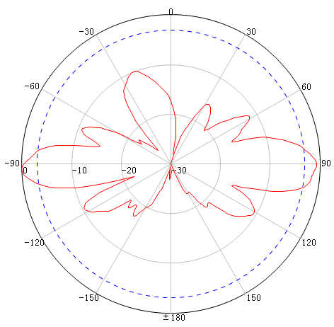
Figure 2 through Figure 5 show the horizontal and vertical radiation patterns.
Figure 2 2.4 GHz horizontal pattern
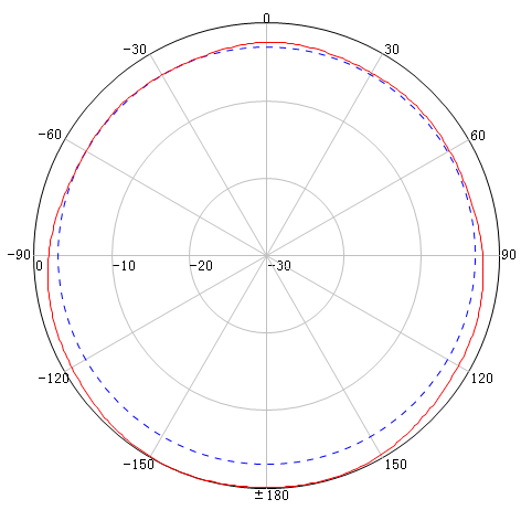
Figure 3 2.4 GHz vertical pattern

Figure 4 5 GHz horizontal pattern
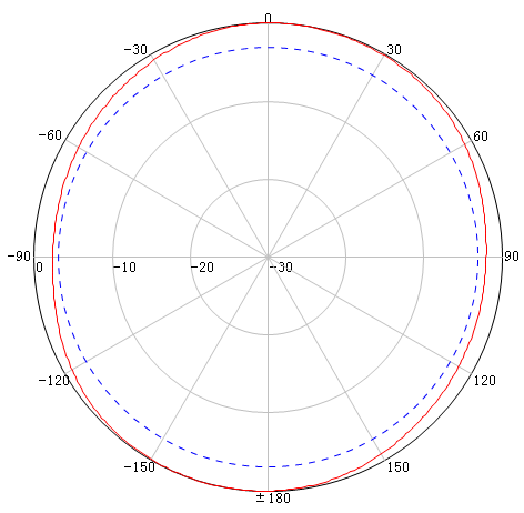
Figure 5 5 GHz vertical pattern
Safety precautions
|
|
WARNING! · Installing antennas carries some level of risk. For your safety, read the following safety precautions carefully before your operation. · Keep the antenna away from power sources, street lamps, power distribution boxes, or other places that might cause electrical shock. · Do not touch any power lines for your safety. |
· Keep safety in mind when you select your installation site. Keep away from electric power lines and other lines.
· Do not work alone when you install the antenna.
· Do not use a metal ladder. Do not work on a wet or windy day. Dress properly, for example, shoes with rubber soles. Wear rubber gloves.
· If the antenna, antenna cable, or any other installation accessory drops, get away from it to avoid bodily injury.
· To avoid any potential hazards, always have a professional handle power connection rather than attempting it yourself.
· If an accident, for example, electrical shock, occurs, immediately call for qualified emergency help.
Installation guidelines
To ensure optimal performance of the antenna, follow these guidelines:
· Install the antenna vertically with the connector side facing downwards.
· Keep the antenna away from metal obstacles, such as heating pipes and air conditioners.
· The material and thickness of walls determine the number of walls that the RF signal can penetrate. 5 GHz signal attenuation is large. Avoid signal penetration through solid walls.
Choosing a mounting location
To ensure optimal coverage, follow these guidelines when choosing a mounting location for the antenna:
· Perform site surveys to determine the antenna mounting location and height. Make sure no obstruction, especially no solid walls and metal plates, exists between the antenna and the target coverage area.
· The antenna installation location must be as close as possible to the AP to reduce the antenna cable length and signal loss.
· The AP must be installed at a location where wires (cables or fibers) and power (local power supply or PoE) can reach.
Mounting the antenna and lightning arrester
|
|
IMPORTANT: When you apply weatherproof tape to a cable connection, follow these restrictions and guidelines: · Make sure you attach the adhesive side of the tape to the connector. · Pull the tape as needed for overlap. · Start wrapping at the top of the connector, and overlap the tape to half-width. Avoid creases or wrinkles and press the tape against the connection so that there are no gaps. Smooth each wrapped layer with your hands to ensure full adhesion. |
The antenna is installed outdoors. You must install a lightning arrester for it. The lightning arrester can be installed on the AP or on the antenna connector. No lightning arrester is provided with the antenna. Purchase one yourself.
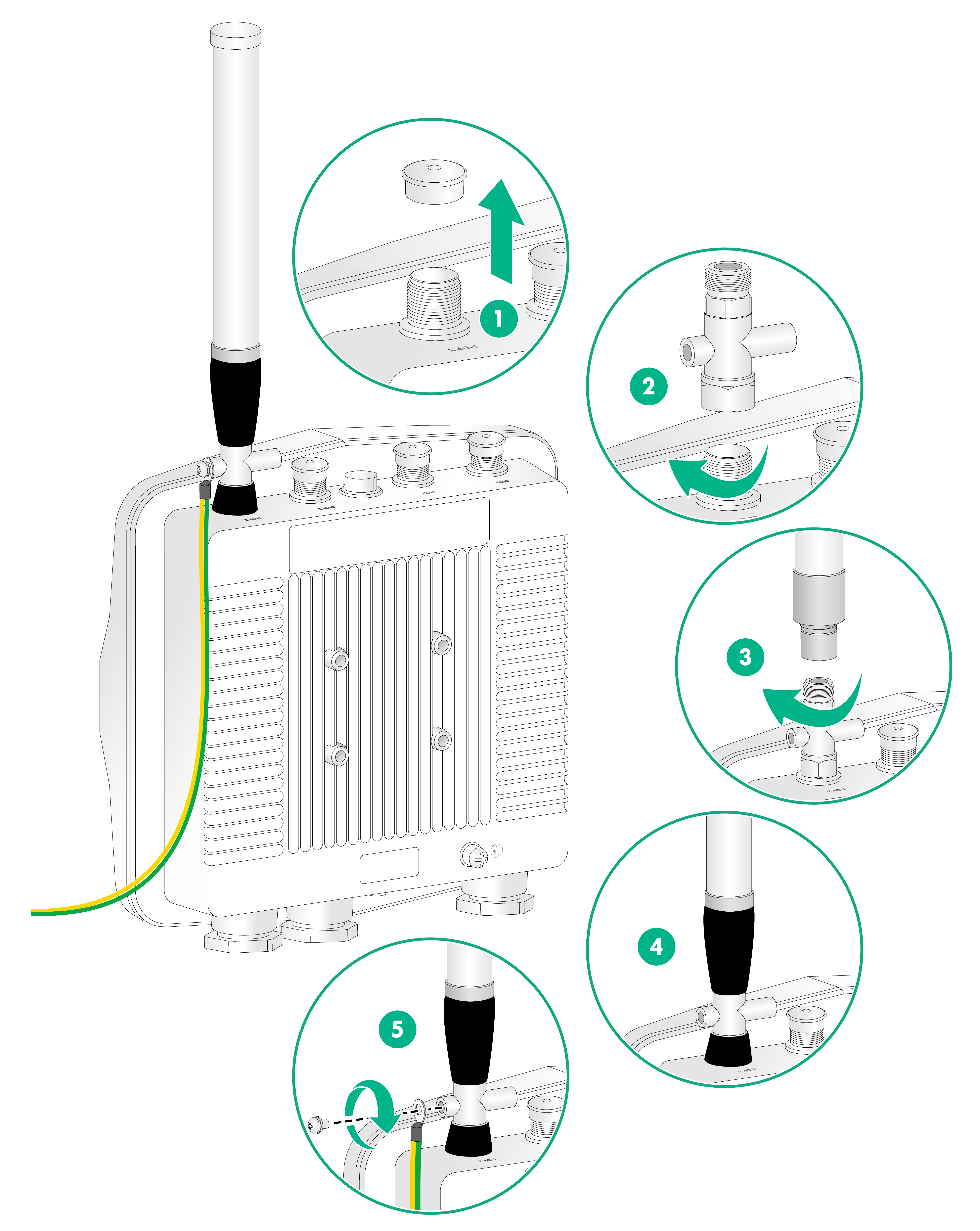
To mount the antenna and lighting arrester:
1. Remove the weatherproof cap from the antenna connector on the AP.
2. Connect a lighting arrester to the antenna connector.
3. Connect the antenna to the lightning arrester.
4. Wrap each connection with weatherproof tape until the entire connection is wrapped. Smooth the tape edges to ensure full adhesion.
5. Ground the lighting arrester.
Figure 6 Mounting the antenna and lightning arrester