- Table of Contents
-
- 11-Network Management and Monitoring Configuration Examples
- 01-H3C_NQA_Configuration_Examples
- 02-H3C_NTP_Configuration_Examples
- 03-H3C_SNMP_Configuration_Examples
- 04-H3C_EAA_Configuration_Examples
- 05-H3C_Mirroring_Configuration_Examples
- 06-H3C_NetStream_Configuration_Examples
- 07-H3C_sFlow_Configuration_Examples
- Related Documents
-
| Title | Size | Download |
|---|---|---|
| 02-H3C_NTP_Configuration_Examples | 231.78 KB |
H3C NTP Configuration Examples
Software version: Release 7577P04
Document version: 6W100-20190330
Copyright © 2019 New H3C Technologies Co., Ltd. All rights reserved.
No part of this manual may be reproduced or transmitted in any form or by any means without prior written consent of New H3C Technologies Co., Ltd.
Except for the trademarks of New H3C Technologies Co., Ltd., any trademarks that may be mentioned in this document are the property of their respective owners.
The information in this document is subject to change without notice.
Contents
Example: Configuring the NTP client/server mode
Example: Configuring the NTP broadcast mode
Configuring Switch B, Switch D, and Switch E
Example: Configuring the NTP multicast mode
Example: Configuring NTP authentication in client/server mode
Example: Configuring the IPv6 NTP client/server mode
Example: Configuring the IPv6 NTP multicast mode
Example: Configuring NTP authentication in broadcast mode
Configuring Switch B, Switch D, and Switch E
Introduction
This document provides NTP configuration examples.
Prerequisites
This document is not restricted to specific software or hardware versions.
The configuration examples in this document were created and verified in a lab environment, and all the devices were started with the factory default configuration. When you are working on a live network, make sure you understand the potential impact of every command on your network.
This document assumes that you have basic knowledge of NTP.
Example: Configuring the NTP client/server mode
Network configuration
As shown in Figure 1, Switch A is an NTP server. For time synchronization on the network, configure the NTP client/server mode so that Switch B and Switch C synchronize with Switch A.

Software versions used
This configuration example was created and verified on S7500E-CMW710-R7577P01.
Procedures
Configuring Switch A
# Assign an IP address to VLAN-interface 2.
<SwitchA> system-view
[SwitchA] interface Vlan-interface 2
[SwitchA-Vlan-interface2] ip address 1.0.1.11 24
[SwitchA-Vlan-interface2] quit
# Enable the NTP service.
[SwitchA] ntp-service enable
# Specify the local clock as the reference source, with stratum level 2.
[SwitchA] ntp-service refclock-master 2
Configuring Switch B
# Assign an IP address to VLAN-interface 2. (Details not shown.)
# Enable the NTP service.
<SwitchB> system-view
[SwitchB] ntp-service enable
# Specify Switch A as the NTP server of Switch B so that Switch B is synchronized to Switch A.
[SwitchB] ntp-service unicast-server 1.0.1.11
Configuring Switch C
# Assign an IP address to VLAN-interface 2. (Details not shown.)
# Enable the NTP service.
<SwitchC> system-view
[SwitchC] ntp-service enable
# Specify Switch A as the NTP server of Switch C so that Switch C is synchronized to Switch A.
[SwitchC] ntp-service unicast-server 1.0.1.11
Verifying the configuration
If the configuration is correct, Switch B and Switch C synchronize the time with Switch A. The following uses Switch B as an example to verify the configuration.
# Verify that Switch B has synchronized to Switch A, and the clock stratum level is 3 on Switch B and 2 on Switch A.
[SwitchB] display ntp-service status
Clock status: synchronized
Clock stratum: 3
System peer: 1.0.1.11
Local mode: client
Reference clock ID: 1.0.1.11
Leap indicator: 00
Clock jitter: 0.003479 s
Stability: 0.000 pps
Clock precision: 2^-18
Root delay: 1.95313 ms
Root dispersion: 28.38135 ms
Reference time: d5ed8cd5.577006ea Wed, Sep 25 2013 16:24:53.341
# Verify that an IPv4 NTP association has been established between Switch B and Switch A.
[SwitchB] display ntp-service sessions
source reference stra reach poll now offset delay disper
********************************************************************************
[12345]1.0.1.11 127.127.1.0 2 255 64 38 -10.22 1.9531 3.3416
Notes: 1 source(master), 2 source(peer), 3 selected, 4 candidate, 5 configured.
Total sessions: 1
Configuration files
· Switch A:
#
interface Vlan-interface2
ip address 1.0.1.11 255.255.255.0
#
ntp-service enable
ntp-service refclock-master 2
#
· Switch B:
#
interface Vlan-interface2
ip address 1.0.1.12 255.255.255.0
#
ntp-service enable
ntp-service unicast-server 1.0.1.11
#
· Switch C:
#
interface Vlan-interface2
ip address 1.0.1.13 255.255.255.0
#
ntp-service enable
ntp-service unicast-server 1.0.1.11
#
Example: Configuring the NTP broadcast mode
Network configuration
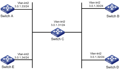
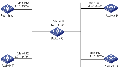
As shown in Figure 2, the devices are on the same network segment (3.0.1.0/24). For time synchronization on the network, configure the NTP broadcast mode so that the devices synchronize with Switch C.
Software versions used
This configuration example was created and verified on S7500E-CMW710-R7577P01.
Procedures
Configuring Switch C
# Enable the NTP service.
<SwitchC> system-view
[SwitchC] ntp-service enable
# Specify the local clock as the reference source, with stratum level 2.
[SwitchC] ntp-service refclock-master 2
# Assign an IP address to VLAN-interface 2.
[SwitchC] interface Vlan-interface 2
[SwitchC-Vlan-interface2] ip address 3.0.1.31 24
# Configure Switch C to operate in broadcast server mode and send broadcast messages from VLAN-interface 2.
[SwitchC-Vlan-interface2] ntp-service broadcast-server
Configuring Switch A
# Assign an IP address to VLAN-interface 2. (Details not shown.)
# Enable the NTP service on Switch A.
<SwitchA> system-view
[SwitchA] ntp-service enable
# Configure Switch A to operate in broadcast client mode and receive broadcast messages on VLAN-interface 2.
[SwitchA-Vlan-interface2] ntp-service broadcast-client
Configuring Switch B, Switch D, and Switch E
The configuration procedure is the same for Switch A, Switch B, Switch D, and Switch E. See "Configuring Switch A" for the configuration procedure.
Verifying the configuration
If the configuration is correct, Switch A, Switch B, Switch D, and Switch E synchronize the time with Switch C. The following uses Switch A as an example to verify the configuration.
# Verify that Switch A has synchronized to Switch C, and the clock stratum level is 3 on Switch A and 2 on Switch C.
[SwitchA-Vlan-interface2] display ntp-service status
Clock status: synchronized
Clock stratum: 3
System peer: 3.0.1.31
Local mode: bclient
Reference clock ID: 3.0.1.31
Leap indicator: 00
Clock jitter: 0.000061 s
Stability: 0.000 pps
Clock precision: 2^-18
Root delay: 0.00000 ms
Root dispersion: 7951.43127 ms
Reference time: d5ee8d88.2faabed0 Thu, Sep 26 2013 10:40:08.186
# Verify that an IPv4 NTP association has been established between Switch A and Switch C.
[SwitchA-Vlan-interface2] display ntp-service sessions
source reference stra reach poll now offset delay disper
********************************************************************************
[1234]3.0.1.31 127.127.1.0 2 254 64 82 -2.190 0.0000 7937.5
Notes: 1 source(master), 2 source(peer), 3 selected, 4 candidate, 5 configured.
Total sessions: 1
Configuration files
· Switch C:
#
interface Vlan-interface2
ip address 3.0.1.31 255.255.255.0
ntp-service broadcast-server
#
ntp-service enable
ntp-service refclock-master 2
#
· Switch A:
#
interface Vlan-interface2
ip address 3.0.1.33 255.255.255.0
ntp-service broadcast-client
#
ntp-service enable
#
· Switch B:
#
interface Vlan-interface2
ip address 3.0.1.30 255.255.255.0
ntp-service broadcast-client
#
ntp-service enable
#
· Switch D:
#
interface Vlan-interface2
ip address 3.0.1.32 255.255.255.0
ntp-service broadcast-client
#
ntp-service enable
#
· Switch E:
#
interface Vlan-interface2
ip address 3.0.1.34 255.255.255.0
ntp-service broadcast-client
#
ntp-service enable
#
Example: Configuring the NTP multicast mode
Network configuration
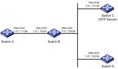
As shown in Figure 3, the devices are on different network segments. For time synchronization on the network, configure the NTP multicast mode so that the devices synchronize with Switch C.
Software versions used
This configuration example was created and verified on S7500E-CMW710-R7577P01.
Procedures
Configuring Switch C
# Enable the NTP service.
<SwitchC> system-view
[SwitchC] ntp-service enable
# Specify the local clock as the reference source, with stratum level 2.
[SwitchC] ntp-service refclock-master 2
# Assign an IP address to VLAN-interface 2.
[SwitchC] interface Vlan-interface 2
[SwitchC-Vlan-interface2] ip address 3.0.1.31 24
# Configure Switch C to operate in multicast server mode and send multicast messages from VLAN-interface 2.
[SwitchC-Vlan-interface2] ntp-service multicast-server
Configuring Switch D
# Enable the NTP service.
<SwitchD> system-view
[SwitchD] ntp-service enable
# Assign an IP address to VLAN-interface 2.
[SwitchD] interface Vlan-interface 2
[SwitchD-Vlan-interface2] ip address 3.0.1.32 24
# Configure Switch D to operate in multicast client mode and receive multicast messages on VLAN-interface 2.
[SwitchD-Vlan-interface2] ntp-service multicast-client
Configuring Switch B
# Assign an IP address to VLAN-interface 2. (Details not shown.)
# Enable the NTP service.
<SwitchB> system-view
[SwitchB] ntp-service enable
# Configure Switch B to operate in multicast client mode and receive multicast messages on VLAN-interface 2.
[SwitchB-Vlan-interface2] ntp-service multicast-client
[SwitchB-Vlan-interface2] quit
Because Switch A and Switch C are on different subnets, you must enable the multicast functions on Switch B before Switch A can receive multicast messages from Switch C.
# Enable IP multicast routing and IGMP.
[SwitchB] multicast routing
[SwitchB] interface vlan-interface 2
[SwitchB-Vlan-interface2] pim dm
[SwitchB-Vlan-interface2] quit
[SwitchB] vlan 3
[SwitchB-vlan3] port Ten-GigabitEthernet 1/0/1
[SwitchB-vlan3] quit
[SwitchB] interface vlan-interface 3
[SwitchB-Vlan-interface3] ip address 1.0.1.10 24
[SwitchB-Vlan-interface3] igmp enable
[SwitchB-Vlan-interface3] igmp static-group 224.0.1.1
[SwitchB-Vlan-interface3] quit
[SwitchB] igmp-snooping
[SwitchB-igmp-snooping] quit
[SwitchB] interface Ten-GigabitEthernet 1/0/1
[SwitchB-Ten-GigabitEthernet1/0/1] igmp-snooping static-group 224.0.1.1 vlan 3
Configuring Switch A
# Enable the NTP service.
<SwitchA> system-view
[SwitchA] ntp-service enable
# Assign an IP address to VLAN-interface 3.
[SwitchA] interface Vlan-interface 3
[SwitchA-Vlan-interface3] ip address 1.0.1.11 24
# Configure Switch A to operate in multicast client mode and receive multicast messages on VLAN-interface 3.
[SwitchA-Vlan-interface3] ntp-service multicast-client
Verifying the configuration
If the configuration is correct, Switch A, Switch B, and Switch D synchronize the time with Switch C. The following uses Switch A as an example to verify the configuration.
# Verify that Switch A has synchronized to Switch C, and the clock stratum level is 3 on Switch A and 2 on Switch C.
[SwitchA-Vlan-interface3] display ntp-service status
Clock status: synchronized
Clock stratum: 3
System peer: 3.0.1.31
Local mode: bclient
Reference clock ID: 3.0.1.31
Leap indicator: 00
Clock jitter: 0.000061 s
Stability: 0.000 pps
Clock precision: 2^-18
Root delay: 1.69373 ms
Root dispersion: 1950.18005 ms
Reference time: d5ee9b15.2f3a684d Thu, Sep 26 2013 11:37:57.184
Configuration files
· Switch A:
#
ntp-service enable
#
interface Vlan-interface3
ip address 1.0.1.11 255.255.255.0
ntp-service multicast-client
#
· Switch B:
#
ntp-service enable
#
multicast routing
#
igmp-snooping
#
interface Vlan-interface2
ip address 3.0.1.30 255.255.255.0
pim dm
ntp-service multicast-client
#
interface Vlan-interface3
ip address 1.0.1.10 255.255.255.0
igmp enable
igmp static-group 224.0.1.1
#
interface Ten-GigabitEthernet1/0/1
port access vlan 3
igmp-snooping static-group 224.0.1.1 vlan 3
#
· Switch C:
#
ntp-service enable
ntp-service refclock-master 2
#
interface Vlan-interface2
ip address 3.0.1.31 255.255.255.0
ntp-service multicast-server
#
· Switch D:
#
ntp-service enable
#
interface Vlan-interface2
ip address 3.0.1.32 255.255.255.0
ntp-service multicast-client
#
Example: Configuring NTP authentication in client/server mode
Network configuration
As shown in Figure 4, Switch A is an NTP server. For time synchronization on the network, configure the NTP client/server mode so that the devices synchronize with Switch A. Configure NTP authentication so that Switch A is authenticated before synchronizing the devices.

Software versions used
This configuration example was created and verified on S7500E-CMW710-R7577P01.
Procedures
Configuring Switch A
# Assign an IP address to VLAN-interface 2.
<SwitchA> system-view
[SwitchA] interface Vlan-interface 2
[SwitchA-Vlan-interface2] ip address 1.0.1.11 24
# Enable the NTP service.
[SwitchA] ntp-service enable
# Specify the local clock as the reference source, with stratum level 2.
[SwitchA] ntp-service refclock-master 2
# Enable NTP authentication on Switch A.
[SwitchA] ntp-service authentication enable
# Configure a plaintext authentication key, specifying the key ID as 42 and key string as aNiceKey.
[SwitchA] ntp-service authentication-keyid 42 authentication-mode md5 simple aNiceKey
# Configure the key as a trusted key.
[SwitchA] ntp-service reliable authentication-keyid 42
Configuring Switch B
# Assign an IP address to VLAN-interface 2. (Details not shown.)
# Enable the NTP service.
<SwitchB> system-view
[SwitchB] ntp-service enable
# Enable NTP authentication on Switch B.
[SwitchB] ntp-service authentication enable
# Configure a plaintext authentication key, specifying the key ID as 42 and key string as aNiceKey.
[SwitchB] ntp-service authentication-keyid 42 authentication-mode md5 simple aNiceKey
# Configure the key as a trusted key.
[SwitchB] ntp-service reliable authentication-keyid 42
# Specify Switch A as the NTP server of Switch B, and associate the server with key 42.
[SwitchB] ntp-service unicast-server 1.0.1.11 authentication-keyid 42
Configuring Switch C
# Assign an IP address to VLAN-interface 2. (Details not shown.)
# Enable the NTP service.
<SwitchC> system-view
[SwitchC] ntp-service enable
# Enable NTP authentication on Switch C.
[SwitchC] ntp-service authentication enable
# Configure a plaintext authentication key, specifying the key ID as 42 and key string as aNiceKey.
[SwitchC] ntp-service authentication-keyid 42 authentication-mode md5 simple aNiceKey
# Configure the key as a trusted key.
[SwitchC] ntp-service reliable authentication-keyid 42
# Specify Switch A as the NTP server of Switch C, and associate the server with key 42.
[SwitchC] ntp-service unicast-server 1.0.1.11 authentication-keyid 42
Verifying the configuration
If the configuration is correct, Switch B and Switch C synchronize the time with Switch A. The following uses Switch B as an example to verify the configuration.
# Verify that Switch B has synchronized to Switch A, and the clock stratum level is 3 on Switch B and 2 on Switch A.
[SwitchB] display ntp-service status
Clock status: synchronized
Clock stratum: 3
System peer: 1.0.1.11
Local mode: client
Reference clock ID: 1.0.1.11
Leap indicator: 00
Clock jitter: 0.005096 s
Stability: 0.000 pps
Clock precision: 2^-18
Root delay: 0.00655 ms
Root dispersion: 1.15869 ms
Reference time: d0c62687.ab1bba7d Mon, Sep 30 2013 16:06:26.764
# Verify that an IPv4 NTP association has been established between Switch B and Switch A.
[SwitchB] display ntp-service sessions
source reference stra reach poll now offset delay disper
********************************************************************************
[1245]1.0.1.11 127.127.1.0 2 1 64 519 -0.0 0.0065 0.0
Notes: 1 source(master),2 source(peer),3 selected,4 candidate,5 configured.
Total sessions : 1
Configuration files
· Switch A:
#
interface Vlan-interface2
ip address 1.0.1.11 255.255.255.0
#
ntp-service enable
ntp-service authentication enable
ntp-service authentication-keyid 42 authentication-mode md5 cipher $c$3$4j3SKCgQWBK3Un41B9U0JXzJX9i7IuNoSqi
ntp-service reliable authentication-keyid 42
ntp-service refclock-master 2
#
· Switch B:
#
interface Vlan-interface2
ip address 1.0.1.12 255.255.255.0
#
ntp-service enable
ntp-service authentication enable
ntp-service authentication-keyid 42 authentication-mode md5 cipher $c$3$22eIc8l796cpudZqiaAZ2SLzIfrgzFTVYn8X
ntp-service reliable authentication-keyid 42
ntp-service unicast-server 1.0.1.11 authentication-keyid 42
#
· Switch C:
#
interface Vlan-interface2
ip address 1.0.1.13 255.255.255.0
#
ntp-service enable
ntp-service authentication enable
ntp-service authentication-keyid 42 authentication-mode md5 cipher $c$3$XJzVmJ1TJbWyYAXpPXxF7JiEOZag8CehibM8
ntp-service reliable authentication-keyid 42
ntp-service unicast-server 1.0.1.11 authentication-keyid 42
#
Example: Configuring SNTP
Network configuration
As shown in Figure 5, Switch A is an NTP server. For time synchronization on the network, configure Switch B and Switch C as SNTP clients to synchronize with Switch A.
Software versions used
This configuration example was created and verified on S7500E-CMW710-R7577P01.
Procedures
Configuring Switch A
# Assign an IP address to VLAN-interface 2.
<SwitchA> system-view
[SwitchA] interface Vlan-interface 2
[SwitchA-Vlan-interface2] ip address 1.0.1.11 24
# Enable the NTP service.
[SwitchA] ntp-service enable
# Specify the local clock as the reference source, with stratum level 2.
[SwitchA] ntp-service refclock-master 2
Configuring Switch B
# Assign an IP address to VLAN-interface 2. (Details not shown.)
# Enable the SNTP service.
<SwitchB> system-view
[SwitchB] sntp enable
# Specify Switch A as the NTP server of Switch B.
[SwitchB] sntp unicast-server 1.0.1.11
Configuring Switch C
# Assign an IP address to VLAN-interface 2. (Details not shown.)
# Enable the SNTP service.
<SwitchC> system-view
[SwitchC] sntp enable
# Specify Switch A as the NTP server of Switch C.
[SwitchC] sntp unicast-server 1.0.1.11
Verifying the configuration
If the configuration is correct, Switch B and Switch C synchronize the time with Switch A. The following uses Switch B as an example to verify the configuration.
# Verify that an SNTP association has been established between Switch B and Switch A, and Switch B has synchronized to Switch A.
[SwitchB] display sntp sessions
SNTP server Stratum Version Last receive time
1.0.1.11 2 4 Thu, Sep 26 2013 17:25:09.121 (Synced)
Configuration files
· Switch A:
#
interface Vlan-interface2
ip address 1.0.1.11 255.255.255.0
#
ntp-service enable
ntp-service refclock-master 2
#
· Switch B:
#
interface Vlan-interface2
ip address 1.0.1.12 255.255.255.0
#
sntp enable
sntp unicast-server 1.0.1.11
#
· Switch C:
#
interface Vlan-interface2
ip address 1.0.1.13 255.255.255.0
#
sntp enable
sntp unicast-server 1.0.1.11
#
Example: Configuring the IPv6 NTP client/server mode
Network configuration
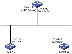
As shown in Figure 1, Switch A is an NTP server on the IPv6 network. For time synchronization on the network, configure the IPv6 NTP client/server mode so that Switch B and Switch C synchronize with Switch A.
Figure 6 Network diagram
Software versions used
This configuration example was created and verified on S7500E-CMW710-R7577P01.
Procedures
Configuring Switch A
# Assign an IPv6 address to VLAN-interface 2.
<SwitchA> system-view
[SwitchA] interface vlan-interface 2
[SwitchA-Vlan-interface2] ipv6 address 3000::34 64
[SwitchA-Vlan-interface2] quit
# Enable the NTP service.
[SwitchA] ntp-service enable
# Specify the local clock as the reference source, with stratum level 2.
[SwitchA] ntp-service refclock-master 2
Configuring Switch B
# Assign an IPv6 address to VLAN-interface 2. (Details not shown.)
# Enable the NTP service.
<SwitchB> system-view
[SwitchB] ntp-service enable
# Specify Switch A as the NTP server of Switch B so that Switch B is synchronized to Switch A.
[SwitchB] ntp-service unicast-server 3000::34
Configuring Switch C
# Assign an IPv6 address to VLAN-interface 2. (Details not shown.)
# Enable the NTP service.
<SwitchC> system-view
[SwitchC] ntp-service enable
# Specify Switch A as the NTP server of Switch C so that Switch C is synchronized with Switch A.
[SwitchC] ntp-service unicast-server 3000::34
Verifying the configuration
If the configuration is correct, Switch B and Switch C synchronize the time with Switch A. The following uses Switch B as an example to verify the configuration.
# Verify that Switch B has synchronized to Switch A, and the clock stratum level is 3 on Switch B and 2 on Switch A.
[SwitchB] display ntp-service status
Clock status: synchronized
Clock stratum: 3
System peer: 3000::34
Local mode: client
Reference clock ID: 95.197.17.40
Leap indicator: 00
Clock jitter: 0.003479 s
Stability: 0.000 pps
Clock precision: 2^-18
Root delay: 1.95313 ms
Root dispersion: 28.38135 ms
Reference time: d5ed8cd5.577006ea Wed, Sep 25 2013 16:24:53.341
# Verify that an IPv6 NTP association has been established between Switch B and Switch A.
[SwitchB] display ntp-service ipv6 sessions
Notes: 1 source(master), 2 source(peer), 3 selected, 4 candidate, 5 configured.
Source: [12345] 3000::34
Reference: 127.127.1.0 Clock stratum: 2
Reachabilities: 3 Poll interval: 64
Last receive time: 62 Offset: 0.1272
Roundtrip delay: 1.8158 Dispersion: 188.47
Total sessions: 1
Configuration files
· Switch A:
#
interface Vlan-interface2
ipv6 address 3000::34/64
#
ntp-service enable
ntp-service refclock-master 2
#
· Switch B:
#
interface Vlan-interface2
ipv6 address 3000::35/64
#
ntp-service enable
ntp-service ipv6 unicast-server 3000::34
#
· Switch C:
#
interface Vlan-interface2
ipv6 address 3000::36/64
#
ntp-service enable
ntp-service ipv6 unicast-server 3000::34
#
Example: Configuring the IPv6 NTP multicast mode
Network configuration
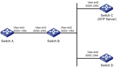
As shown in Figure 3, Switch C is an NTP server on the IPv6 network, and the devices are on different network segments. For time synchronization on the network, configure the IPv6 NTP multicast mode so that the devices synchronize with Switch C.
Figure 7 Network diagram
Software versions used
This configuration example was created and verified on S7500E-CMW710-R7577P01.
Procedures
Configure routing protocols so that all devices can reach each other. (Details not shown.)
Configuring Switch C
# Enable the NTP service.
<SwitchC> system-view
[SwitchC] ntp-service enable
# Specify the local clock as the reference source, with stratum level 2.
[SwitchC] ntp-service refclock-master 2
# Assign an IPv6 address to VLAN-interface 2.
[SwitchC] interface Vlan-interface 2
[SwitchC-Vlan-interface2] ipv6 address 3000::2 64
# Configure Switch C to operate in IPv6 multicast server mode and send multicast messages from VLAN-interface 2.
[SwitchC-Vlan-interface2] ntp-service ipv6 multicast-server ff24::1
[SwitchC-Vlan-interface2] quit
Configuring Switch D
# Assign an IP address to VLAN-interface 2. (Details not shown.)
# Enable the NTP service.
<SwitchD> system-view
[SwitchD] ntp-service enable
# Configure Switch D to operate in IPv6 multicast client mode and receive multicast messages on VLAN-interface 2.
[SwitchD-Vlan-interface2] ntp-service ipv6 multicast-client ff24::1
[SwitchD-Vlan-interface2] quit
Configuring Switch B
# Assign an IP address to VLAN-interface 2 and VLAN-interface 3. (Details not shown.)
# Enable the NTP service.
<SwitchB> system-view
[SwitchB] ntp-service enable
# Configure Switch B to operate in IPv6 multicast client mode and receive multicast messages on VLAN-interface 2.
[SwitchB-Vlan-interface2] ntp-service ipv6 multicast-client ff24::1
[SwitchB-Vlan-interface2] quit
Because Switch A and Switch C are on different subnets, you must enable IPv6 multicast functions on Switch B so that Switch A can receive multicast messages from Switch C.
# Enable IPv6 multicast functions.
[SwitchB] ipv6 multicast routing
[SwitchB-mrib6] quit
[SwitchB] interface vlan-interface 2
[SwitchB-Vlan-interface2] ipv6 pim dm
[SwitchB-Vlan-interface2] quit
[SwitchB] vlan 3
[SwitchB-vlan3] port Ten-GigabitEthernet 1/0/1
[SwitchB-vlan3] quit
[SwitchB] interface vlan-interface 3
[SwitchB-Vlan-interface3] mld enable
[SwitchB-Vlan-interface3] mld static-group ff24::1
[SwitchB-Vlan-interface3] quit
[SwitchB] mld-snooping
[SwitchB-mld-snooping] quit
[SwitchB] interface Ten-GigabitEthernet 1/0/1
[SwitchB-Ten-GigabitEthernet1/0/1] mld-snooping static-group ff24::1 vlan 3
[SwitchB-mld-snooping] quit
Configuring Switch A
# Assign an IP address to VLAN-interface 3. (Details not shown.)
# Enable the NTP service.
<SwitchA> system-view
[SwitchA] ntp-service enable
# Configure Switch A to operate in IPv6 multicast client mode and receive multicast messages on VLAN-interface 3.
[SwitchA-Vlan-interface3] ntp-service ipv6 multicast-client ff24::1
[SwitchA-Vlan-interface3] quit
Verifying the configuration
If the configuration is correct, Switch A, Switch B, and Switch D synchronize the time with Switch C. The following uses Switch A as an example to verify the configuration.
# Verify that Switch A has synchronized to Switch C, and the clock stratum level is 3 on Switch A and 2 on Switch C.
[SwitchA] display ntp-service status
Clock status: synchronized
Clock stratum: 3
System peer: 3000::2
Local mode: bclient
Reference clock ID: 165.84.121.65
Leap indicator: 00
Clock jitter: 0.000061 s
Stability: 0.000 pps
Clock precision: 2^-14
Root delay: 1.69373 ms
Root dispersion: 1950.18005 ms
Reference time: d5ee9b15.2f3a684d Thu, Sep 26 2013 11:37:57.184
Configuration files
· Switch A:
#
ntp-service enable
#
interface Vlan-interface3
ipv6 address 2000::1/64
ntp-service ipv6 multicast-client ff24::1
#
· Switch B:
#
ntp-service enable
#
ipv6 multicast routing
#
mld-snooping
#
interface Vlan-interface2
ipv6 address 3000::1/64
ipv6 pim dm
ntp-service ipv6 multicast-client ff24::1
#
interface Vlan-interface3
ipv6 address 2000::2/64
mld enable
mld static-group ff24::1
#
interface Ten-GigabitEthernet1/0/1
port access vlan 3
mld-snooping static-group ff24::1 vlan 3
#
· Switch C:
#
ntp-service enable
ntp-service refclock-master 2
#
interface Vlan-interface2
ipv6 address 3000::2/64
ntp-service ipv6 multicast-server ff24::1
#
· Switch D:
#
ntp-service enable
#
interface Vlan-interface2
ipv6 address 3000::3/64
ntp-service ipv6 multicast-client ff24::1
#
Example: Configuring NTP authentication in broadcast mode
Network configuration
As shown in Figure 4, the devices are on the same network segment (3.0.1.0/24). Configure the NTP broadcast mode so that the devices synchronize with Switch C. Configure NTP authentication so that Switch C is authenticated before synchronizing the devices.
Figure 8 Network diagram
Software versions used
This configuration example was created and verified on S7500E-CMW710-R7577P01.
Procedures
Configure Switch C
# Enable the NTP service.
<SwitchC> system-view
[SwitchC] ntp-service enable
# Specify the local clock as the reference source, with stratum level 2.
[SwitchC] ntp-service refclock-master 2
# Enable NTP authentication on Switch C. Configure a plaintext authentication key, specifying the key ID as 88 and key string as 123456. Configure the key as a trusted key.
[SwitchC] ntp-service authentication enable
[SwitchC] ntp-service authentication-keyid 88 authentication-mode md5 simple 123456
[SwitchC] ntp-service reliable authentication-keyid 88
# Specify Switch C as an NTP broadcast server, and associate key 88 with Switch C.
[SwitchC] interface vlan-interface 2
[SwitchC-Vlan-interface2] ip address 3.0.1.31 24
[SwitchC-Vlan-interface2] ntp-service broadcast-server authentication-keyid 88
[SwitchC-Vlan-interface2] quit
Configure Switch A
# Enable the NTP service on Switch A.
<SwitchA> system-view
[SwitchA] ntp-service enable
# Enable NTP authentication on Switch A. Configure a plaintext authentication key, specifying the key ID as 88 and key string as 123456. Configure the key as a trusted key.
[SwitchA] ntp-service authentication enable
[SwitchA] ntp-service authentication-keyid 88 authentication-mode md5 simple 123456
[SwitchA] ntp-service reliable authentication-keyid 88
# Configure Switch A to operate in NTP broadcast client mode and receive NTP broadcast messages on VLAN-interface 2.
[SwitchA] interface vlan-interface 2
[SwitchA-Vlan-interface2] ntp-service broadcast-client
[SwitchA-Vlan-interface2] ip address 3.0.1.33 24
[SwitchA-Vlan-interface2] quit
Configuring Switch B, Switch D, and Switch E
The configuration procedure is the same for Switch A, Switch B, Switch D, and Switch E. See "Configure Switch A" for the configuration procedure.
Verifying the configuration
If the configuration is correct, Switch A, Switch B, Switch D, and Switch E synchronize the time with Switch C. The following example uses Switch A to verify the configuration.
# Verify that Switch A has synchronized to Switch C, and the clock stratum level is 3 on Switch A and 2 on Switch C.
[SwitchA] display ntp-service status
Clock status: synchronized
Clock stratum: 3
System peer: 3.0.1.31
Local mode: bclient
Reference clock ID: 3.0.1.31
Leap indicator: 00
Clock jitter: 0.000092 s
Stability: 0.000 pps
Clock precision: 2^-18
Root delay: 2.42615 ms
Root dispersion: 1950.98877 ms
Reference time: d5eed631.2f498d71 Thu, Sep 26 2013 15:50:09.184
Configuration files
· Switch A, Switch B, Switch D, and Switch E:
#
interface Vlan-interface2
ip address 3.0.1.33 255.255.255.0
ntp-service broadcast-client
#
ntp-service enable
ntp-service authentication enable
ntp-service authentication-keyid 88 authentication-mode md5 cipher $c$3$pU6KvpS80MadhM2zM
CCSR07HX4qEbJhHvQ==
ntp-service reliable authentication-keyid 88
#
· Switch C:
#
interface Vlan-interface2
ip address 3.0.1.31 255.255.255.0
ntp-service broadcast-server authentication-keyid 88
#
ntp-service enable
ntp-service authentication enable
ntp-service authentication-keyid 88 authentication-mode md5 cipher $c$3$iJudDKiqCVO+gOaG53
63/fz4M3dQvHo2Fw==
ntp-service reliable authentication-keyid 88
ntp-service refclock-master 3
#
Related documentation
· H3C S7500E Switch Series Network Management and Monitoring Configuration Guide-R757X
· H3C S7500E Switch Series Network Management and Monitoring Command Reference-R757X
