| Title | Size | Downloads |
|---|---|---|
| H3C HDM2 IPMI Basics Command Reference-6W100-book.pdf | 1.36 MB |
- Table of Contents
- Related Documents
-
| Title | Size | Download |
|---|---|---|
| book | 1.36 MB |
|
|
|
H3C HDM2 |
|
IPMI Basics Command Reference |
|
|
|
|
|
New H3C Technologies Co., Ltd. http://www.h3c.com
Software version: HDM2-1.23 and later, HDM2-1.58 and later Document version: 20230913-6W100 |
Copyright © 2023, New H3C Technologies Co., Ltd. and its licensors
All rights reserved
No part of this manual may be reproduced or transmitted in any form or by any means without prior written consent of New H3C Technologies Co., Ltd.
Trademarks
Except for the trademarks of New H3C Technologies Co., Ltd., any trademarks that may be mentioned in this document are the property of their respective owners.
Notice
The information in this document is subject to change without notice. All contents in this document, including statements, information, and recommendations, are believed to be accurate, but they are presented without warranty of any kind, express or implied. H3C shall not be liable for technical or editorial errors or omissions contained herein.
Contents
Applicable products and versions
Obtain the reason for the most recent restart
Obtain total power-on time of a chassis
Obtain the chassis self-test result
Obtain the current chassis power status
Set the power-on policy for a chassis
Obtain the supported power-on policies of a chassis
Obtain server version information
Obtain server GUID information
Obtain the current status of all sensors
Obtain sensor type information
Obtain the list of supported sensors in a chassis
Perform a server self-test on HDM
Obtain the reading of a sensor
Set the alarm threshold for a sensor
Obtain current session information
Obtain server power status and UID LED status
Obtain information about all HDM users
Obtain brief HDM user information
Set the password for an HDM user
Obtain the IP address obtaining method for a network port
Obtain the IP address of a network port
Obtain the MAC address of a network port
Obtain the subnet mask of a network port
Set the IP address obtaining method for a network port
Specify a static IP address for a network port
Specify the subnet mask for a network port
Specify the gateway address for a network port
Obtain the IPv6 address of a network port
Specify a static IPv6 address for a network port
Specify the prefix length for a network port
Obtain the prefix length of a network port
Obtain the IPv6 address obtaining method for a network port
Set the IPv6 address obtaining method for a network port
Specify the IPv6 gateway address for a network port
Set the one-time next boot option
Remove the configured one-time next boot option
Configure the server to enter the BIOS setup utility after startup
Obtain the number of present PCIe modules
Obtain PCIe module information
Obtain port information on an Ethernet adapter
Obtain the number of supported CPUs and DIMMs
Obtain OCP network adapter status
Obtain security bezel LED configuration
Obtain storage controller list information
Obtain information about the specified storage controller
Obtain the logical drive list for the specified storage controller
Obtain information about the specified logical drive
Obtain the physical drive list for the specified storage controller
Obtain information about the specified physical drive for a storage controller
Obtain the physical drive list
Obtain information about the specified physical drive
Set the mode of the specified storage controller
Set the attributes of the specified storage controller
Clear configuration of the specified storage controller
Delete the specified logical drive
Modify the attributes of the specified logical drive
Add/Remove the specified hot spare drive
Modify the status of the specified physical drive
Locate the specified physical drive
Obtain the drive alarm thresholds
Set the drive alarm thresholds
Obtain the power-on delay time
Obtain the state of weak password dictionary validation
Set the state of weak password dictionary validation
Obtain ICMP outbound rules of the firmware
Configure ICMP outbound rules on the firmware
Obtain the status of a network port
Obtain the number of network ports
Obtain channel information of a network port
Obtain the name of a network port
Set the status of a network port
Obtain the link status of dedicated and shared network ports
Obtain HDM network service information
Configure HDM network service settings
Obtain permissions of all user roles
Set permissions for a custom user role
Trigger an immediate network restart
Delete all network firewall rules
Obtain the status setting of a network port
Obtain network port in use in active/standby mode
Set the enabling status of SNMP traps
Set the location of an SNMP trap node
Set the SNMP trap contact information
Specify the severity levels of SNMP traps to be reported
Obtain SNMP trap general settings
Specify the primary NTP server
Specify the secondary NTP server
Specify the tertiary NTP server
Configure time synchronization with NTP servers
Obtain the IP address of the tertiary NTP server
Obtain the NTP synchronization interval
Obtain HDM firmware information
Obtain BIOS firmware information
Obtain PFR firmware information about a system board
Obtain service USB device configuration
Set service USB device configuration
Obtain Wi-Fi service enabling status
Set Wi-Fi service enabling status
Obtain the number of taskservice tasks and the current task ID
Obtain taskservice task details
Set the enabling status of the dedicated management interface
View the enabling status of the dedicated management interface
Obtain overall information about SEL logs
Obtain information about an SEL log
Obtain information about a packet transmitted for an SEL entry
Obtain information about the serial port connected to the SOL
Obtain information about the serial port connected to a panel
Set the severity levels for SMTP alert emails
Obtain the severity levels for SMTP alert emails
Obtain the address of the SMTP server
Obtain rsyslog configuration information
Obtain information about rsyslog single-channel server configuration
Set rsyslog message configuration
Configure rsyslog single-channel server settings
Test rsyslog single-channel server settings
Configure event log association with the health center
Reload the configuration file for fans
Obtain the maximum number of supported power supplies
Check whether the installed power supply are as required
Obtain the presence, AC input, and DC input status of a power supply
Obtain the cold backup state of a power supply
Configure a power supply to enter in cold backup
Configure a power supply to exit from cold backup
Obtain the manufacturer information of a power supply
Obtain the model of a power supply
Obtain the maximum output power of a power supply
Obtain power supply information displayed on the Web interface
Obtain the current output power of a power supply
Obtain the range of the power cap value
Obtain the power information of a power supply
Obtain the second firmware revision of a power supply
Obtain GPU power capping information
Obtain power information of the past day or week
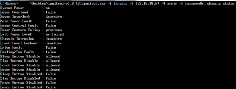
Using IPMItool to obtain chassis status
Using IPMItool to obtain chassis information
IPMI command conventions
About IPMI
Intelligent Platform Management Interface (IPMI) is an industry standard for managing peripheral devices in server systems. You can use IPMI to monitor the physical health status of servers from different vendors, such as temperature, voltage, fan modules, power supplies to achieve unified management of servers from different vendors.
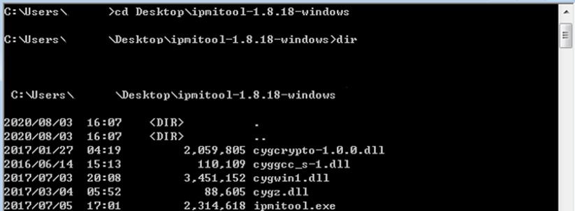
About IPMItool
IPMItool is an open source IPMI client tool that supports both Linux and Windows operating systems and is the most commonly used IPMI client tool. IPMItool accesses the IPMI interface of a server through commands. As shown in Figure 1, open the Windows cmd and access the IPMItool directory to execute IPMI commands.
Figure 1 Windows Command Prompt
Command format
An IPMI command uses the ipmitool -I connect_type -H hostname -U username -P password <command> format, where:
· -I connect_type—Specifies the connection method used to access the device to be managed. The connect_type argument is fixed to lanplus, which indicates that the device to be managed will be accessed as required in the IPMI 2.0 specification. The value lan is not supported by default. You need to enable RMCP in the Service Configuration.
· -H hostname—Specifies the IP address of the device to be managed.
· -U username -P password—Specifies the HDM username and password of the device to be managed.
· <command>—Specifies the action to be taken. This argument can be a string (chassis status for example) or a hexadecimal raw code (raw 0x00 0x01). For more information about this argument, see the specific command.
· -L—Specifies the session privilege, which is Administrator by default. You can use this keyword to specify user privileges when establishing a session for access. The specified privileges and command privileges cannot be higher than the current user's privileges. When -L oem keyword is specified, the session privileges are consistent with the privileges of the current user.
|
User privileges |
Available -L privileges |
|
Administrator |
Administrator, Operator, User, oem |
|
Operator |
Operator, User, oem |
|
User |
User, oem |
|
CustomRole1-5 |
oem |
|
|
NOTE: The length of the raw code (raw 0x00 0x01) in a command cannot exceed 255 bytes. |
Request and response
For some commands, the request and response will be displayed as a hexadecimal raw string. Table 1 and Table 2 display the example data fields in such a request and a response, respectively.
Table 1 Example data fields in a request
|
Field |
Description |
|
Data[1] |
Specifies a single-byte field. The byte is displayed as 2-digit hexadecimal numbers. For more information, see the parameters of the specific command. |
|
Data[1:3] |
Specifies a multi-byte field. This field contains three bytes: Data[1], Data[2], and Data[3]. Each byte is displayed as 2-digit hexadecimal numbers. For more information, see the parameters of the specific command. |
Table 2 Example data fields in a response
|
Field |
Description |
|
Data[1] |
Specifies the first returned byte. For more information, see the response of the specific command. |
|
Data[9:16] |
Specifies the 9th to 16th returned bytes. For more information, see the response of the specific command. |
|
Bits[7:1] |
Specifies the seven highest bits of a byte. In a response, each byte contains eight bits: 7, 6, 5, 4, 3, 2, 1, and 0, where 7 represents the highest bit and 0 represents the second lowest bit. |
|
Bits[5:4] |
Specifies the fifth and fourth lowest bits of a byte. In a response, each byte contains eight bits: 7, 6, 5, 4, 3, 2, 1, and 0, where 7 represents the highest bit and 0 represents the second lowest bit. |
Applicable products and versions
HDM is the first-generation management software for the H3C server baseboard controller, which is applicable to H3C G3 and G5 server products. HDM2 is the second-generation software and is applicable to H3C G6 server products.
In this document, some commands may be compatible with HDM G3/G5 products, so you may see explanations revision records that include compatibility and supported version information for products of earlier generations. Any revision records outlined in the Change history for HDM-1.xx/HDM-2.xx/HDM-3.xx are supported on HDM2-compatible products. The revision version numbers that apply to HDM2 will be named as HDM2-x.xx.
For the interface content of H3C G3/G5 server products, see the manual applicable to the corresponding software version.
Interfaces described in this document are applicable to H3C G6 servers. For more information, see H3C Servers HDM2 User Guide.
Support for interface functions depends on the product specifications.
Permissions
Port description
|
Permission module |
Description |
|
User accounts |
Includes: · User management · Advanced password configuration · Directory management · Import or export · Unified management |
|
Basic configuration |
Includes: · Network configuration (network ports, NTP, SNMP, LLDP, DNS) · Alarm settings · Asset tag configurations. |
|
Remote control, |
Includes: · RAID · BIOS options · Boot items · UID · SOL · MCA policies · System resource monitoring threshold configuration |
|
Remote media |
Includes remote image mounting. |
|
Security |
Includes: · KVM configuration · VNC configuration · SSL · Firewall · Service configuration |
|
Power control |
Includes: · Power supply · Fans · Energy-saving control · NMI |
|
Maintenance |
Includes: · Log management · Video screenshots · Firmware management · Firmware restart |
|
Password modification |
Includes user self-password configuration. |
|
System audit |
Includes: · Event logs · Operation logs · One-click log downloading and exporting |
|
Information query. |
Typically, GET interfaces have query permissions. |
Standard IPMI commands
Chassis management
Obtain current chassis status
Use chassis status to obtain the current status of a chassis.
Syntax
ipmitool -I connect_type -H hostname -U username -P password chassis status
Required permission
Information query
Examples
# Obtain the current chassis status.
COMMAND>ipmitool -I lanplus -H 192.168.50.166 -U admin -P Password@_ chassis status
System Power : on
Power Overload : false
Power Interlock : inactive
Main Power Fault : false
Power Control Fault : false
Power Restore Policy : previous
Last Power Event : command
Chassis Intrusion : inactive
Front-Panel Lockout : inactive
Drive Fault : false
Cooling/Fan Fault : false
Sleep Button Disable : allowed
Diag Button Disable : allowed
Reset Button Disable : allowed
Power Button Disable : allowed
Sleep Button Disabled: true
Diag Button Disabled : true
Reset Button Disabled: true
Power Button Disabled: true
Obtain the reason for the most recent restart
Use chassis restart_cause to obtain the reason for the most recent restart.
Syntax
ipmitool -I connect_type -H hostname -U username -P password chassis restart_cause
Required permission
Information query
Examples
# Obtain the reason for the most recent restart.
COMMAND>ipmitool -I lanplus -H 192.168.50.166 -U admin -P Password@_ chassis restart_cause
System restart cause: chassis power control command
Obtain total power-on time of a chassis
Use chassis poh to obtain the total power-on time of a chassis.
Syntax
ipmitool -I connect_type -H hostname -U username -P password chassis poh
Required permission
Information query
Examples
# Obtain the total power-on time of a chassis.
COMMAND>ipmitool -I lanplus -H 192.168.50.166 -U admin -P Password@_ chassis poh
POH Counter : 8 days, 13 hours
Obtain the chassis self-test result
Use chassis selftest to obtain the self-test result of a chassis.
|
|
NOTE: When the BMC starts up, it performs a self-test on the FRUs. If no FRU information is detected, the test is considered failed. |
Syntax
ipmitool -I connect_type -H hostname -U username -P password chassis selftest
Required permission
Information query
Examples
# Obtain the self-test result of a chassis.
COMMAND>ipmitool -I lanplus -H 192.168.50.166 -U admin -P Password@_ chassis selftest
Self Test Results : passed
Chassis power management
Obtain the current chassis power status
Use power status to obtain the current power status of a chassis.
Syntax
ipmitool -I connect_type -H hostname -U username -P password power status
Required permission
Information query
Examples
# Obtain the current power status of a chassis.
COMMAND>ipmitool -I lanplus -H 192.168.50.166 -U admin -P Password@_ power status
Chassis Power is on
Power on a chassis
Use power on to power on a chassis.
Syntax
ipmitool -I connect_type -H hostname -U username -P password power { up | on }
Required permission
Power control
Usage guidelines
The up and on keyword function the same. You can use either keyword to power on the chassis.
Examples
# Power on a chassis.
COMMAND>ipmitool -I lanplus -H 192.168.50.166 -U admin -P Password@_ power on
Chassis Power Control: Up/On
Power off a chassis
Use power off to power off a chassis.
Syntax
ipmitool -I connect_type -H hostname -U username -P password power { down | off }
Required permission
Power control
Usage guidelines
The down and off keyword function the same. You can use either keyword to power off the chassis.
Examples
# Power off a chassis.
COMMAND>ipmitool -I lanplus -H 192.168.50.166 -U admin -P Password@_ power off
Chassis Power Control: Down/Off
Restart a chassis
Use power reset to restart a chassis. This operation disconnects the server power.
Syntax
ipmitool -I connect_type -H hostname -U username -P password power reset
Required permission
Power control
Examples
# Restart a chassis.
COMMAND>ipmitool -I lanplus -H 192.168.50.166 -U admin -P Password@_ power reset
Chassis Power Control: Reset
Trigger NMI diagnosis
Use this command to trigger NMI diagnosis.
Syntax
ipmitool -I connect_type -H hostname -U username -P password power diag
Required permission
Power control
Examples
# Trigger NMI diagnosis.
COMMAND>ipmitool -I lanplus -H 192.168.50.166 -U admin -P Password@_ power diag
Chassis Power Control: Diag
Change history
|
Version |
Change description |
|
HDM-2.0.07 |
Added this command. |
Set the power-on policy for a chassis
Use chassis policy to set the power-on policy that takes effect when the server is connected to the power source.
Syntax
ipmitool -I connect_type -H hostname -U username -P password chassis policy power_policy
Table 3 Request field description
|
Field |
Description |
|
power_policy |
Specify the power-on policy. Supported options: · always-on—Enables the server to power on automatically. · previous—Enables the server to return to the power state on the previous power-off. · always-off—Enables the server to stay off. |
Default
The power-on policy is previous. The server returns to the power state on the previous power-off.
Required permission
Power control
Examples
# Set the power-on policy for a chassis.
COMMAND>ipmitool -I lanplus -H 192.168.50.166 -U admin -P Password@_ chassis policy always-on
Set chassis power restore policy to always-on
Obtain the supported power-on policies of a chassis
Use chassis policy list to obtain the supported power-on policies of a chassis.
Syntax
ipmitool -I connect_type -H hostname -U username -P password chassis policy list
Required permission
Information query
Examples
# Obtain the supported power-on policies of a chassis.
COMMAND>ipmitool -I lanplus -H 192.168.50.166 -U admin -P Password@_ chassis policy list
Supported chassis power policy: always-off always-on previous
Server information obtaining
Obtain server version information
Use mc info to obtain server version information.
Syntax
ipmitool -I connect_type -H hostname -U username -P password mc info
Required permission
Information query
Examples
# Obtain server version information from HDM 1.11.9.
COMMAND>ipmitool -I lanplus -H 192.168.50.166 -U admin -P Password@_ mc info
Device ID : 32
Device Revision : 1
Firmware Revision : 1.11
IPMI Version : 2.0
Manufacturer ID : 25506
Manufacturer Name : Unknown (0x63A2)
Product ID : 27 (0x001b)
Product Name : Unknown (0x1B)
Device Available : yes
Provides Device SDRs : no
Additional Device Support :
Sensor Device
SDR Repository Device
SEL Device
FRU Inventory Device
IPMB Event Receiver
IPMB Event Generator
Chassis Device
Aux Firmware Rev Info :
0x09
0x00
0x00
0x00
Obtain server GUID information
Use mc guid to obtain the globally unique identifier (GUID) information of the server.
Syntax
ipmitool -I connect_type -H hostname -U username -P password mc guid
Required permission
Information query
Examples
# Obtain server GUID information.
COMMAND>ipmitool -I lanplus -H 192.168.50.166 -U admin -P Password@_ mc guid
System GUID : 65e3328a-1019-04b0-e611-0edc168afafa
Timestamp : 03/02/2024 22:07:06
Obtain the current status of all sensors
Use sdr to obtain the current status of sensors in a chassis.
Syntax
ipmitool -I connect_type -H hostname -U username -P password sdr
ipmitool -I connect_type -H hostname -U username -P password sdr list
Required permission
Information query
Usage guidelines
This command returns the readings and status of all sensors in the chassis. The server is in healthy state only when all sensors are in heathy state.
Examples
# Obtain the current status and readings of all sensors in a chassis.
COMMAND>ipmitool -I lanplus -H 192.168.50.166 -U admin -P Password@_ sdr
18-P/S 1 Zone | 39 degrees C | ok
19-P/S 2 Zone | 36 degrees C | ok
24-BMC Zone | 44 degrees C | ok
32-Outlet_Temp 1 | 45 degrees C | ok
33-Outlet_Temp 2 | 41 degrees C | ok
16-P/S 1 | 36 degrees C | ok
17-P/S 2 | 36 degrees C | ok
02-CPU 1 | 52 degrees C | ok
03-CPU 2 | 51 degrees C | ok
04-CPU 1 DTS | -40 degrees C | ok
05-CPU 2 DTS | -41 degrees C | ok
06-P1 DIMM Ch1-3 | 36 degrees C | ok
07-P1 DIMM Ch4-6 | 38 degrees C | ok
08-P2 DIMM Ch1-3 | 39 degrees C | ok
25-PCI 1 | 61 degrees C | ok
26-PCI 2 | no reading | ns
28-PCI 1 Zone | 44 degrees C | ok
29-PCI 2 Zone | no reading | ns
10-Front HD Max | 35 degrees C | ok
12-Rear HD Max | no reading | ns
22-HD Controller | 38 degrees C | ok
31-LOM Card | 43 degrees C | ok
01-Inlet Temp | 28 degrees C | ok
23-Expander Card | no reading | ns
13-Rear HD Zone | no reading | ns
09-P2 DIMM Ch4-6 | 37 degrees C | ok
15-PCH | 55 degrees C | ok
20-VR P1 | 43 degrees C | ok
21-VR P2 | 45 degrees C | ok
14-M.2 Zone | no reading | ns
FAN5_F_Speed | 5000 RPM | ok
FAN4_R_Speed | no reading | ns
FAN5_R_Speed | 5300 RPM | ok
FAN7_F_Speed | 5000 RPM | ok
FAN2_F_Speed | 4900 RPM | ok
FAN4_F_Speed | no reading | ns
FAN7_R_Speed | 5200 RPM | ok
FAN3_R_Speed | 5200 RPM | ok
FAN6_R_Speed | 5300 RPM | ok
FAN1_R_Speed | 5300 RPM | ok
FAN6_F_Speed | 5000 RPM | ok
FAN2_R_Speed | 5300 RPM | ok
FAN3_F_Speed | 5000 RPM | ok
FAN1_F_Speed | 5000 RPM | ok
CPU1_Status | 0x80 | ok
CPU2_Status | 0x80 | ok
PSU1_PIN | 95 Watts | ok
PSU2_PIN | 85 Watts | ok
PSU1_Status | 0x01 | ok
PSU2_Status | 0x01 | ok
FAN1_F_Status | 0x01 | ok
FAN2_F_Status | 0x01 | ok
FAN3_F_Status | 0x01 | ok
FAN4_F_Status | Not Readable | ns
FAN5_F_Status | 0x01 | ok
FAN6_F_Status | 0x01 | ok
FAN7_F_Status | 0x01 | ok
FAN1_R_Status | 0x01 | ok
FAN2_R_Status | 0x01 | ok
FAN3_R_Status | 0x01 | ok
FAN4_R_Status | Not Readable | ns
FAN5_R_Status | 0x01 | ok
FAN6_R_Status | 0x01 | ok
FAN7_R_Status | 0x01 | ok
27-PCI 3 | no reading | ns
30-PCI 3 Zone | no reading | ns
SEL_sensor | 0x00 | ok
Watchdog2 | 0x00 | ok
OverCurrent | 0x01 | ok
11-Front NVMe | no reading | ns
AreaIntrusion | 0x00 | ok
CPU1_DDR_VPP1 | 2.58 Volts | ok
CPU1_DDR_VDDQ1 | 1.22 Volts | ok
CPU1_Vcore | 1.78 Volts | ok
CPU2_DDR_VPP2 | 2.58 Volts | ok
CPU2_DDR_VPP1 | 2.58 Volts | ok
CPU2_DDR_VDDQ2 | 1.22 Volts | ok
CPU2_DDR_VDDQ1 | 1.22 Volts | ok
CPU1_DDR_VPP2 | 2.58 Volts | ok
CPU1_DDR_VDDQ2 | 1.22 Volts | ok
CPU2_Vcore | 1.78 Volts | ok
PSU1_VIN | 231.60 Volts | ok
PSU2_VIN | 232.80 Volts | ok
SYS_3V3 | 3.28 Volts | ok
SYS_5V | 5.12 Volts | ok
SYS_3V_BAT | 3.28 Volts | ok
SYS_12V | 12 Volts | ok
HDD_BP3_12V | no reading | ns
HDD_BP2_12V | no reading | ns
HDD_BP1_12V | no reading | ns
PSU2_VOUT | 12 Volts | ok
PSU1_VOUT | 11.88 Volts | ok
CPU2_VDDQ1_PG | 0x01 | ok
CPU1_VDDQ2_PG | 0x01 | ok
CPU2_DDR_VPP2_PG | 0x01 | ok
CPU2_VDDQ2_PG | 0x01 | ok
SYS_5V_STBY_PG | 0x01 | ok
BP_1_PG | 0x01 | ok
BP_2_PG | 0x01 | ok
CPU1_DDR_VPP2_PG | 0x01 | ok
BP_3_PG | 0x01 | ok
CPU1_DDR_VPP1_PG | 0x01 | ok
CPU2_DDR_VPP1_PG | 0x01 | ok
CPU1_VDDQ1_PG | 0x01 | ok
CPU2_DIMM_B1 | Not Readable | ns
CPU1_DIMM_A6 | 0x40 | ok
CPU2_DIMM_B5 | Not Readable | ns
CPU2_DIMM_B2 | 0x40 | ok
CPU1_DIMM_A1 | Not Readable | ns
CPU2_DIMM_B4 | Not Readable | ns
CPU1_DIMM_A4 | Not Readable | ns
CPU1_DIMM_A7 | Not Readable | ns
CPU2_DIMM_B3 | Not Readable | ns
CPU2_DIMM_B7 | Not Readable | ns
CPU2_DIMM_B8 | Not Readable | ns
CPU1_DIMM_A8 | Not Readable | ns
CPU2_DIMM_B6 | 0x40 | ok
CPU1_DIMM_A5 | Not Readable | ns
CPU1_DIMM_A2 | Not Readable | ns
CPU1_DIMM_A3 | 0x40 | ok
Obtain sensor type information
Use this command to obtain information about a sensor type in a chassis.
Syntax
ipmitool -I connect_type -H hostname -U username -P password sdr type
ipmitool -I connect_type -H hostname -U username -P password sdr type sdr_type
Table 4 Request field description
|
Field |
Description |
|
sdr_type |
Specify a sensor type. |
Required permission
Information query
Examples
· Obtain the list of supported sensor types in a chassis.
COMMAND>ipmitool -I lanplus -H 192.168.50.166 -U admin -P Password@_ sdr type
Sensor Types:
Temperature Voltage
Current Fan
Physical Security Platform Security
Processor Power Supply
Power Unit Cooling Device
Other Memory
Drive Slot / Bay POST Memory Resize
System Firmwares Event Logging Disabled
Watchdog System Event
Critical Interrupt Button
Module / Board Microcontroller
Add-in Card Chassis
Chip Set Other FRU
Cable / Interconnect Terminator
System Boot Initiated Boot Error
OS Boot OS Critical Stop
Slot / Connector System ACPI Power State
Watchdog Platform Alert
Entity Presence Monitor ASIC
LAN Management Subsystem Health
· Obtain information about power supply sensors in a chassis.
COMMAND>ipmitool -I lanplus -H 192.168.50.166 -U admin -P Password@_ sdr type "Power Supply"
PWR_On_TMOUT | 97h | ok | 7.3 | Presence detected
PSU1_Status | C4h | ok | 10.1 | Presence detected
PSU2_Status | C5h | ok | 10.2 | Presence detected
PSU_Redundant | C6h | ok | 10.127 | Fully Redundant
PSU_Mismatch | C7h | ok | 10.126 |
Obtain the list of supported sensors in a chassis
Use sensor list to obtain the list of supported sensors in a chassis.
Syntax
ipmitool -I connect_type -H hostname -U username -P password sensor list
Required permission
Information query
Examples
# Obtain the list of supported sensors in a chassis.
COMMAND>ipmitool -I lanplus -H 192.168.50.166 -U admin -P Password@_ sensor list
Sensor Name | Reading | Unit | Status| Crit low | Major low | Minor low | Minor high| Major high| Crit high
18-P/S 1 Zone | 39.000 | degrees C | ok | na | na | na | 95.000 | 100.000 | na
19-P/S 2 Zone | 36.000 | degrees C | ok | na | na | na | 95.000 | 100.000 | na
24-BMC Zone | 44.000 | degrees C | ok | na | na | na | 95.000 | 100.000 | na
32-Outlet_Temp 1 | 45.000 | degrees C | ok | na | na | na | 95.000 | 100.000 | na
33-Outlet_Temp 2 | 41.000 | degrees C | ok | na | na | na | 95.000 | 100.000 | na
16-P/S 1 | 36.000 | degrees C | ok | na | na | na | 60.000 | 62.000 | na
17-P/S 2 | 36.000 | degrees C | ok | na | na | na | 60.000 | 62.000 | na
02-CPU 1 | 52.000 | degrees C | ok | na | na | na | na | na | na
03-CPU 2 | 51.000 | degrees C | ok | na | na | na | na | na | na
04-CPU 1 DTS | -40.000 | degrees C | ok | na | na | na | -1.000 | na | na
05-CPU 2 DTS | -41.000 | degrees C | ok | na | na | na | -1.000 | na | na
06-P1 DIMM Ch1-3 | 36.000 | degrees C | ok | na | na | na | 89.000 | 95.000 | na
07-P1 DIMM Ch4-6 | 38.000 | degrees C | ok | na | na | na | 89.000 | 95.000 | na
08-P2 DIMM Ch1-3 | 39.000 | degrees C | ok | na | na | na | 89.000 | 95.000 | na
25-PCI 1 | 60.000 | degrees C | ok | na | na | na | 90.000 | 100.000 | na
26-PCI 2 | na | degrees C | na | na | na | na | 90.000 | 100.000 | na
28-PCI 1 Zone | 44.000 | degrees C | ok | na | na | na | 95.000 | 100.000 | na
29-PCI 2 Zone | na | degrees C | na | na | na | na | 95.000 | 100.000 | na
10-Front HD Max | 35.000 | degrees C | ok | na | na | na | 60.000 | na | na
12-Rear HD Max | na | degrees C | na | na | na | na | 60.000 | na | na
22-HD Controller | 38.000 | degrees C | ok | na | na | na | 90.000 | 99.000 | 102.000
31-LOM Card | 43.000 | degrees C | ok | na | na | na | 90.000 | 100.000 | na
01-Inlet Temp | 28.000 | degrees C | ok | na | na | na | 50.000 | 52.000 | 54.000
23-Expander Card | na | degrees C | na | na | na | na | 100.000 | 120.000 | 125.000
13-Rear HD Zone | na | degrees C | na | na | na | na | 95.000 | 100.000 | na
09-P2 DIMM Ch4-6 | 37.000 | degrees C | ok | na | na | na | 89.000 | 95.000 | na
15-PCH | 54.000 | degrees C | ok | na | na | na | 92.000 | 102.000 | na
20-VR P1 | 43.000 | degrees C | ok | na | na | na | 110.000 | 112.000 | na
21-VR P2 | 45.000 | degrees C | ok | na | na | na | 110.000 | 112.000 | na
14-M.2 Zone | na | degrees C | na | na | na | na | 95.000 | 100.000 | na
FAN5_F_Speed | 5000.000 | RPM | ok | na | na | na | na | na | na
FAN4_R_Speed | na | RPM | na | na | na | na | na | na | na
FAN5_R_Speed | 5300.000 | RPM | ok | na | na | na | na | na | na
FAN7_F_Speed | 5000.000 | RPM | ok | na | na | na | na | na | na
FAN2_F_Speed | 5000.000 | RPM | ok | na | na | na | na | na | na
FAN4_F_Speed | na | RPM | na | na | na | na | na | na | na
FAN7_R_Speed | 5200.000 | RPM | ok | na | na | na | na | na | na
FAN3_R_Speed | 5200.000 | RPM | ok | na | na | na | na | na | na
FAN6_R_Speed | 5300.000 | RPM | ok | na | na | na | na | na | na
FAN1_R_Speed | 5300.000 | RPM | ok | na | na | na | na | na | na
FAN6_F_Speed | 5000.000 | RPM | ok | na | na | na | na | na | na
FAN2_R_Speed | 5300.000 | RPM | ok | na | na | na | na | na | na
FAN3_F_Speed | 5000.000 | RPM | ok | na | na | na | na | na | na
FAN1_F_Speed | 5000.000 | RPM | ok | na | na | na | na | na | na
CPU1_Status | 0x0 | discrete | 0x8080| na | na | na | na | na | na
CPU2_Status | 0x0 | discrete | 0x8080| na | na | na | na | na | na
PSU1_PIN | 95.000 | Watts | ok | na | na | na | na | na | na
PSU2_PIN | 85.000 | Watts | ok | na | na | na | na | na | na
PSU1_Status | 0x0 | discrete | 0x0180| na | na | na | na | na | na
PSU2_Status | 0x0 | discrete | 0x0180| na | na | na | na | na | na
FAN1_F_Status | 0x0 | discrete | 0x0180| na | na | na | na | na | na
FAN2_F_Status | 0x0 | discrete | 0x0180| na | na | na | na | na | na
FAN3_F_Status | 0x0 | discrete | 0x0180| na | na | na | na | na | na
FAN4_F_Status | na | discrete | na | na | na | na | na | na | na
FAN5_F_Status | 0x0 | discrete | 0x0180| na | na | na | na | na | na
FAN6_F_Status | 0x0 | discrete | 0x0180| na | na | na | na | na | na
FAN7_F_Status | 0x0 | discrete | 0x0180| na | na | na | na | na | na
FAN1_R_Status | 0x0 | discrete | 0x0180| na | na | na | na | na | na
FAN2_R_Status | 0x0 | discrete | 0x0180| na | na | na | na | na | na
FAN3_R_Status | 0x0 | discrete | 0x0180| na | na | na | na | na | na
FAN4_R_Status | na | discrete | na | na | na | na | na | na | na
FAN5_R_Status | 0x0 | discrete | 0x0180| na | na | na | na | na | na
FAN6_R_Status | 0x0 | discrete | 0x0180| na | na | na | na | na | na
FAN7_R_Status | 0x0 | discrete | 0x0180| na | na | na | na | na | na
27-PCI 3 | na | degrees C | na | na | na | na | 90.000 | 100.000 | na
30-PCI 3 Zone | na | degrees C | na | na | na | na | 95.000 | 100.000 | na
SEL_sensor | 0x0 | discrete | 0x0080| na | na | na | na | na | na
Watchdog2 | 0x0 | discrete | 0x0080| na | na | na | na | na | na
OverCurrent | 0x0 | discrete | 0x0180| na | na | na | na | na | na
11-Front NVMe | na | degrees C | na | na | na | na | 70.000 | na | na
AreaIntrusion | 0x0 | discrete | 0x0080| na | na | na | na | na | na
CPU1_DDR_VPP1 | 2.580 | Volts | ok | na | 2.340 | na | na | 2.760 | na
CPU1_DDR_VDDQ1 | 1.220 | Volts | ok | na | 1.080 | na | na | 1.320 | na
CPU1_Vcore | 1.780 | Volts | ok | na | 1.330 | na | na | 1.880 | na
CPU2_DDR_VPP2 | 2.580 | Volts | ok | na | 2.340 | na | na | 2.760 | na
CPU2_DDR_VPP1 | 2.580 | Volts | ok | na | 2.340 | na | na | 2.760 | na
CPU2_DDR_VDDQ2 | 1.220 | Volts | ok | na | 1.080 | na | na | 1.320 | na
CPU2_DDR_VDDQ1 | 1.220 | Volts | ok | na | 1.080 | na | na | 1.320 | na
CPU1_DDR_VPP2 | 2.580 | Volts | ok | na | 2.340 | na | na | 2.760 | na
CPU1_DDR_VDDQ2 | 1.220 | Volts | ok | na | 1.080 | na | na | 1.320 | na
CPU2_Vcore | 1.780 | Volts | ok | na | 1.330 | na | na | 1.880 | na
PSU1_VIN | 232.800 | Volts | ok | na | na | na | na | na | na
PSU2_VIN | 235.200 | Volts | ok | na | na | na | na | na | na
SYS_3V3 | 3.280 | Volts | ok | na | 2.960 | na | na | 3.600 | na
SYS_5V | 5.120 | Volts | ok | na | 4.480 | na | na | 5.520 | na
SYS_3V_BAT | 3.280 | Volts | ok | na | 2.000 | na | na | 3.680 | na
SYS_12V | 12.000 | Volts | ok | na | 10.800 | na | na | 13.200 | na
HDD_BP3_12V | na | Volts | na | na | na | na | na | na | na
HDD_BP2_12V | na | Volts | na | na | na | na | na | na | na
HDD_BP1_12V | na | Volts | na | na | na | na | na | na | na
PSU2_VOUT | 12.000 | Volts | ok | na | na | na | na | na | na
PSU1_VOUT | 11.880 | Volts | ok | na | na | na | na | na | na
CPU2_VDDQ1_PG | 0x0 | discrete | 0x0180| na | na | na | na | na | na
CPU1_VDDQ2_PG | 0x0 | discrete | 0x0180| na | na | na | na | na | na
CPU2_DDR_VPP2_PG | 0x0 | discrete | 0x0180| na | na | na | na | na | na
CPU2_VDDQ2_PG | 0x0 | discrete | 0x0180| na | na | na | na | na | na
SYS_5V_STBY_PG | 0x0 | discrete | 0x0180| na | na | na | na | na | na
BP_1_PG | 0x0 | discrete | 0x0180| na | na | na | na | na | na
BP_2_PG | 0x0 | discrete | 0x0180| na | na | na | na | na | na
CPU1_DDR_VPP2_PG | 0x0 | discrete | 0x0180| na | na | na | na | na | na
BP_3_PG | 0x0 | discrete | 0x0180| na | na | na | na | na | na
CPU1_DDR_VPP1_PG | 0x0 | discrete | 0x0180| na | na | na | na | na | na
CPU2_DDR_VPP1_PG | 0x0 | discrete | 0x0180| na | na | na | na | na | na
CPU1_VDDQ1_PG | 0x0 | discrete | 0x0180| na | na | na | na | na | na
CPU2_DIMM_B1 | na | discrete | na | na | na | na | na | na | na
CPU1_DIMM_A6 | 0x0 | discrete | 0x4080| na | na | na | na | na | na
CPU2_DIMM_B5 | na | discrete | na | na | na | na | na | na | na
CPU2_DIMM_B2 | 0x0 | discrete | 0x4080| na | na | na | na | na | na
CPU1_DIMM_A1 | na | discrete | na | na | na | na | na | na | na
CPU2_DIMM_B4 | na | discrete | na | na | na | na | na | na | na
CPU1_DIMM_A4 | na | discrete | na | na | na | na | na | na | na
CPU1_DIMM_A7 | na | discrete | na | na | na | na | na | na | na
CPU2_DIMM_B3 | na | discrete | na | na | na | na | na | na | na
CPU2_DIMM_B7 | na | discrete | na | na | na | na | na | na | na
CPU2_DIMM_B8 | na | discrete | na | na | na | na | na | na | na
CPU1_DIMM_A8 | na | discrete | na | na | na | na | na | na | na
CPU2_DIMM_B6 | 0x0 | discrete | 0x4080| na | na | na | na | na | na
CPU1_DIMM_A5 | na | discrete | na | na | na | na | na | na | na
CPU1_DIMM_A2 | na | discrete | na | na | na | na | na | na | na
CPU1_DIMM_A3 | 0x0 | discrete | 0x4080| na | na | na | na | na | na
Table 5 Response field description
|
Field |
Description |
|
Status |
Sensor status. Supported options: · na—A sensor is absent. · ok—A sensor is operating correctly. · nc—A minor error occurs on a sensor. · cr—A major error occurs on a sensor. · nr—A critical error occurs on a sensor. The error is not recoverable. |
Obtain fan status information
Use sensor get to obtain status information of a fan in a chassis.
Syntax
ipmitool -I connect_type -H hostname -U username -P password sensor get FAN_Status
Table 6 Request field description
|
Field |
Description |
|
FAN_Status |
Specify the name of a fan status sensor, for example, FAN1_Status and FAN2_Status. |
Required permission
Information query
Usage guidelines
Make sure the specified sensor name is correct. To obtain the names of supported sensors, execute the sensor list command.
Examples
# Obtain status information of a fan in a chassis.
COMMAND>ipmitool -I lanplus -H 192.168.50.166 -U admin -P Password@_ sensor get FAN1_Status
Locating sensor record...
Sensor ID : FAN1_Status (0x60)
Entity ID : 30.0
Sensor Type (Discrete): Fan
States Asserted : Availability State
[Transition to Running]
Related commands
sensor list
Obtain fan speed information
Use sensor get to obtain the rotation speed information of a fan.
Syntax
ipmitool -I connect_type -H hostname -U username -P password sensor get FAN_Speed
Table 7 Request field description
|
Field |
Description |
|
FAN_Speed |
Specify the name of a fan speed sensor, for example, FAN1_Speed and FAN2_Speed. |
Required permission
Information query
Usage guidelines
Make sure the specified sensor name is correct. To obtain the names of supported sensors, execute the sensor list command.
Examples
# Obtain the rotation speed information of a fan.
COMMAND>ipmitool -I lanplus -H 192.168.50.166 -U admin -P Password@_ sensor get FAN1_Speed
Locating sensor record...
Sensor ID : FAN1_Speed (0x70)
Entity ID : 29.0
Sensor Type (Analog) : Fan
Sensor Reading : 3400 (+/- 0) RPM
Status : ok
Lower Non-Recoverable : na
Lower Critical : na
Lower Non-Critical : na
Upper Non-Critical : na
Upper Critical : na
Upper Non-Recoverable : na
Assertion Events :
Assertions Enabled :
Related commands
sensor list
Perform a server self-test on HDM
Use mc selftest to perform a server self-test on HDM.
Syntax
ipmitool -I connect_type -H hostname -U username -P password mc selftest
Required permission
Information query
Examples
# Perform a server self-test on HDM.
COMMAND>ipmitool -I lanplus -H 192.168.50.166 -U admin -P Password@_ mc selftest
Selftest: passed
Reset HDM
Use mc reset to reset HDM.
Syntax
ipmitool -I connect_type -H hostname -U username -P password mc reset warm
Table 8 Request field description
|
Field |
Description |
|
warm |
Specify warm reset. This operation resets HDM without disconnecting the system power. |
Required permission
Maintenance
Examples
# Reset HDM.
COMMAND>ipmitool -I lanplus -H 192.168.50.166 -U admin -P Password@_ mc reset warm
Sent warm reset command to MC
Obtain the reading of a sensor
Use sensor reading to obtain the reading of a sensor.
Syntax
ipmitool -I connect_type -H hostname -U username -P password sensor reading sensor_id
Table 9 Request field description
|
Field |
Description |
|
sensor_id |
Specify the sensor name. |
Required permission
Information query
Usage guidelines
Make sure the specified sensor name is correct. To obtain the names of supported sensors, execute the sensor list command.
You can use this command to obtain only readings of continuous sensors, such as temperature, voltage, current, power, and speed sensors.
Examples
# Obtain the reading of a sensor.
COMMAND>ipmitool -I lanplus -H 192.168.50.166 -U admin -P Password@_ sensor reading FAN5_F_Speed
FAN5_F_Speed | 5000
Related commands
sensor list
Set the alarm threshold for a sensor
Use sensor thresh to set the alarm threshold for a sensor.
Syntax
ipmitool -I connect_type -H hostname -U username -P password sensor thresh sensor_id threshold value
Table 10 Request field description
|
Field |
Description |
|
sensor_id |
Specify the sensor name. |
|
threshold |
Specify the threshold type. Table 11 displays the available threshold types. |
|
value |
Specify the threshold value. |
Table 11 Available threshold types
|
Type |
Description |
|
unr |
Upper critical alarm threshold. |
|
ucr |
Upper major alarm threshold. |
|
unc |
Upper minor alarm threshold. |
|
lnc |
Lower critical alarm threshold. |
|
lcr |
Lower major alarm threshold. |
|
lnr |
Lower minor alarm threshold. |
|
lower |
Specifies all lower alarm thresholds in the following order: lower minor, lower major, and lower critical. |
|
upper |
Specifies all upper alarm thresholds in the following order: upper minor, upper major, and upper critical. |
Required permission
Maintenance
Usage guidelines
|
|
CAUTION: As a best practice, perform this task under professional guidance. |
Make sure the specified sensor name is correct. To obtain the names of supported sensors, execute the sensor list command.
Examples
# Set the upper minor, upper major, and upper critical thresholds of the HDM temperature sensor to 70°C (158°F), 80°C (176°F), and 90°C (194°F), respectively.
COMMAND>ipmitool -I lanplus -H 192.168.50.166 -U admin -P Password@_ sensor thresh "24-BMC Zone" upper 70 80 90
Locating sensor record '24-BMC Zone'...
Setting sensor "24-BMC Zone" Upper Non-Critical threshold to 70.000
Setting sensor "24-BMC Zone" Upper Critical threshold to 80.000
Setting sensor "24-BMC Zone" Upper Non-Recoverable threshold to 90.000
Related commands
sensor list
Obtain SEL information
Use sel to obtain SEL information.
Syntax
ipmitool -I connect_type -H hostname -U username -P password sel
Required permission
Information query
Examples
# Obtain SEL information.
COMMAND>ipmitool -I lanplus -H 192.168.50.166 -U admin -P Password@_ sel
SEL Information
Version : 1.5 (v1.5, v2 compliant)
Entries : 175
Free Space : 62352 bytes
Percent Used : 4%
Last Add Time : 01/01/2018 08:00:27
Last Del Time : Not Available
Overflow : false
Supported Cmds : 'Delete' 'Partial Add' 'Reserve' 'Get Alloc Info'
# of Alloc Units : 1500
Alloc Unit Size : 18
# Free Units : 3464
Largest Free Blk : 3464
Max Record Size : 13
Obtain FRU information
Use fru to obtain FRU information.
Syntax
ipmitool -I connect_type -H hostname -U username -P password fru
Required permission
Information query
Examples
# Obtain FRU information.
COMMAND>ipmitool -I lanplus -H 192.168.50.166 -U admin -P Password@_ fru
FRU Device Description : Builtin FRU Device (ID 0)
Chassis Type : Rack Mount Chassis
Chassis Part Number : 0200A00T
Chassis Serial : 210200A00TH177000016
Chassis Extra : User Defined
Chassis Extra : 74EACB5A5D7C
Chassis Extra : 6
Chassis Extra : FC9612PW11
Board Mfg Date : Fri Jul 14 00:00:00 2017
Board Mfg : ABC
Board Product : RS23M2C3S
Board Serial : 02A3U0H176000003
Board Part Number : 0302A3U0
Board Extra : 210235A2DBH177000014
Product Manufacturer : Unis Huashan Technologies Co., Ltd.
Product Name : UniServer R2700 G3
Product Part Number : 0200A00T
Product Serial : 210200A00TH177000016
Product Asset Tag : @!!
FRU Device Description : Expander (ID 1)
Device not present (Requested sensor, data, or record not found)
FRU Device Description : BackPanel1 (ID 2)
Board Mfg Date : Thu Apr 20 08:00:00 2017
Board Mfg : ABC
Board Product : RS33B08SA
Board Serial : 02A3GNH174000023
Board Part Number : 0302A3GN
Board Extra : 02A3GNH174000023
FRU Device Description : HBA_Raid (ID 12)
Board Mfg Date : Sat Jun 17 08:00:00 2017
Board Mfg : ABC
Board Product : RS33H2P8SA
Board Serial : 02A3H0H176000047
Board Part Number : 0302A3H0
Board Extra : 02A3H0H176000047
FRU Device Description : BackPanel2 (ID 13)
Device not present (Requested sensor, data, or record not found)
FRU Device Description : mLOM (ID 3)
Unknown FRU header version 0xff
FRU Device Description : PcieCard1 (ID 5)
Device not present (Requested sensor, data, or record not found)
FRU Device Description : PcieCard2 (ID 8)
Device not present (Requested sensor, data, or record not found)
FRU Device Description : BackPanel3 (ID 14)
Device not present (Requested sensor, data, or record not found)
FRU Device Description : Riser1 (ID 16)
Board Mfg Date : Thu Jun 8 08:00:00 2017
Board Mfg : ABC
Board Product : RS33RGPX16
Board Serial : 02A3H9H176000059
Board Part Number : 0302A3H9
Board Extra : 02A3H9H176000059
FRU Device Description : Riser2 (ID 17)
Device not present (Requested sensor, data, or record not found)
FRU Device Description : M.2 (ID 15)
Device not present (Requested sensor, data, or record not found)
FRU Device Description : Mezzine (ID 19)
Device not present (Requested sensor, data, or record not found)
FRU Device Description : LP_Card (ID 20)
Device not present (Requested sensor, data, or record not found)
FRU Device Description : MB BMC (ID 21)
Product Manufacturer : ABC
Product Name : BMC
Product Part Number : HDM
Product Version : 1.11.09
FRU Device Description : MB BIOS (ID 22)
Product Manufacturer : ABC
Product Name : BIOS
Product Part Number : C35
Product Version : 1.01.04
Obtain current session information
Use session info to obtain information about the current HDM sessions.
Syntax
ipmitool -I connect_type -H hostname -U username -P password session info { active | all | id id | handle handle }
Table 12 Request field description
|
Field |
Description |
|
active |
Specify active sessions. |
|
all |
Specify all sessions. |
|
id id |
Specify the ID of a user, in the 0xnnnnnnnn format. |
|
handle handle |
Specify a session handle, in the 0xnn format. |
Required permission
Information query
Examples
# Obtain information about active sessions.
COMMAND>ipmitool -I lanplus -H 192.168.50.166 -U admin -P Password@_ session info active
session handle : 13
slot count : 36
active sessions : 1
user id : 2
privilege level : ADMINISTRATOR
session type : IPMIv2/RMCP+
channel number : 0x01
console ip : 192.16.1.196
console mac : 2c:41:38:9f:9b:ab
console port : 2043
Obtain server power status and UID LED status
Use this command to obtain server power status and UID LED status.
Syntax
ipmitool -I connect_type -H hostname -U username -P password raw 0x00 0x01
Required permission
Information query
Examples
# Obtain server power status and UID LED status.
COMMAND>ipmitool -I lanplus -H 192.168.50.166 -U admin -P Password@_ raw 0x00 0x01
41 01 40 f0
Table 13 Response field description
|
Field |
Description |
|
Data[1] |
Bits[7:1]: N/A Bit[0]: Current power status. Supported options: · 1b—Power-on. · 0b—Power-off. |
|
Data[2] |
N/A |
|
Data[3] |
Bit[7]: Reserved. Bit[6]: Indicates whether UID LED is supported. Supported options: · 1b—Supported. · 0b—Not supported. Bits[5:4]: UID LED status. · Supported options for G3: ¡ 00b—Off. ¡ 01b—Steady on. ¡ 10b—Flashing. ¡ 11b—Reserved. · Supported options for G5/G6: ¡ 00b—Off. ¡ 01b—Flashing. ¡ 10b—Steady on. ¡ 11b—Reserved. For G3/G5, bits[3:0]: N/A For G6, bits [3:1]: N/A For G6, [0] – Whether chassis intrusion detection is supported, where 1b indicates that chassis intrusion detection is supported, and 0b indicates that chassis intrusion detection is not supported. |
|
Data[4] |
N/A |
Change history
|
Version |
Change description |
|
HDM2-1.57 |
Added support for identifying whether chassis intrusion detection is supported. |
|
HDM-2.0.04 |
Changed the UID LED status for G5 servers to the standard. |
Set server UID LED status
Use this command to set server UID LED status.
Syntax
ipmitool -I connect_type -H hostname -U username -P password raw 0x00 0x04 sec uid_state ac_uid
Table 14 Request field description
|
Request field |
Description |
|
sec |
Specify the state duration, where 0 indicates a permanent state. |
|
uid_state |
Specify the status of the UID LED. Supported options: · 0x00: On. · 0x01: Off. |
|
ac_uid |
Not specified/0-0xff |
Table 15 UID LED action
|
Value of sec |
Value of uid_state |
Value of ac_uid |
LED action |
|
Not specified |
Not specified |
Not specified |
Flash for 15 seconds |
|
0-0xff |
Not specified |
Not specified |
Flash for the specified seconds. If sec is 0, the command turns off the LED. |
|
0-0xff |
0x01 |
Not specified//0-0xff |
Steady on for the specified seconds. A sec value of 0 represents permanently on. · If the value for ac_uid is not specified, the UID LED is steady on for the specified seconds. · If the value for ac_uid is not specified, a sec value of 0 represents permanently on. · If you specify a value for ac_uid and a sec value of 0 represents permanently on: ¡ An ac_uid value of non-zero represents that the LED is off after an AC or BMC restart. ¡ An ac_uid value of 0 represents that the UID LED status does not change after an AC or BMC restart. |
|
0-0xff |
0x00 |
Not specified//0-0xff |
· If sec is 0, the command turns off the UID LED. · If sec is not 0, the UID LED flashes for the specified seconds. After the flashing ends, the UID LED will be off. · No ac_uid value can take effect. |
Required permission
Remote control
Examples
# Configure the server UID LED to flash for 15 seconds.
COMMAND> ipmitool-I lanplus-H 127.0.0.1 –U admin –P Password@_ raw 0x00 0x04
# Configure the server UID LED to flash for 2 seconds.
COMMAND>ipmitool –I lanplus –H 127.0.0.1 –U admin –P Password@_raw 0x00 0x04 0x2
# Configure the server UID LED to be steady on.
COMMAND>ipmitool -I lanplus -H 192.168.50.166 -U admin -P Password@_ raw 0x00 0x04 0x00 0x01
# Turn off the server UID LED.
COMMAND>ipmitool -I lanplus -H 192.168.50.166 -U admin -P Password@_ raw 0x00 0x04 0x00 0x00
# Configure the server UID LED to be steady on after an AC or BMC restart.
COMMAND>ipmitool -I lanplus -H 192.168.50.166 -U admin -P Password@_ raw 0x00 0x04 0x00 0x01 0x01
Change history
|
Version |
Change description |
|
HDM2-1.53 |
Added the field for setting the UID LED status after an AC or BMC restart. |
Obtain FRU information
Use this command to obtain FRU information and saves the information to the fru.bin file in the current directory.
Syntax
ipmitool -I connect_type -H hostname -U username -P password fru read ID directory/xxx.bin
Required permission
Information query
Examples
# Obtain system board FRU information and save the information to the current directory.
COMMAND>ipmitool -I lanplus -H 192.168.30.41 -U admin -P Password@_ fru read 0 ./fru.bin
Fru Size : 992 bytes
Done
Change history
|
Version |
Change description |
|
HDM-2.0.07 |
Added this command. |
User management
Obtain information about all HDM users
Use user list to obtain information about all HDM users.
Syntax
ipmitool -I connect_type -H hostname -U username -P password user list
Required permission
Information query
Examples
# Obtain information about all HDM users.
COMMAND>ipmitool -I lanplus -H 192.168.50.166 -U admin -P Password@_ user list
ID Name Callin Link Auth IPMI Msg Channel Priv Limit
1 false false true ADMINISTRATOR
2 admin false false true ADMINISTRATOR
Obtain brief HDM user information
Use user summary to obtain brief HDM user information.
Syntax
ipmitool -I connect_type -H hostname -U username -P password user summary
Required permission
Information query
Examples
# Obtain brief HDM user information.
COMMAND>ipmitool -I lanplus -H 192.168.50.166 -U admin -P Password@_ user summary
Maximum IDs : 16
Enabled User Count : 2
Fixed Name Count : 2
Add an HDM user
Use user set name to add an HDM user.
Syntax
ipmitool -I connect_type -H hostname -U username -P password user set name user_id username
Table 16 Request field description
|
Field |
Description |
|
user_id |
Specify a user ID. Make sure the user ID is no larger than the value of the Maximum IDs field in the output from the user summary command. |
|
username |
Specify a username, a case-sensitive string of 1 to 16 characters. Only letters, digits, dots (.), hyphens (-), underscores (_), and at signs (@) are allowed. |
Default
The administrator users exist and the usernames are admin and anonymous.
Required permission
User accounts
Usage guidelines
If the specified user ID already exists with a different username, the command changes the existing username of the user.
To add a user, you must also specify the password, enable HDM access, and specify the HDM user role for the user.
Examples
# Add an HDM user, set the user ID to 9, and specify the username as test.
COMMAND>ipmitool -I lanplus -H 192.168.50.166 -U admin -P Password@_ user set name 9 test
# View information about all HDM users.
COMMAND>ipmitool -I lanplus -H 192.168.50.166 -U admin -P Password@_ user list
ID Name Callin Link Auth IPMI Msg Channel Priv Limit
1 false false true ADMINISTRATOR
2 admin false false true ADMINISTRATOR
9 test true false false NO ACCESS
Related commands
user set password
user enable
user priv
Change history
|
Version |
Change description |
|
HDM2-1.20 |
Added a default administrator user and support for at signs (@). |
Set the password for an HDM user
Use user set password to set the password for an HDM user.
Syntax
ipmitool -I connect_type -H hostname -U username -P password user set password user_id password
Table 17 Request field description
|
Field |
Description |
|
user_id |
Specify a user ID. Make sure the user ID already exists. |
|
password |
Specify the password string, a case-sensitive string. The password contains a maximum of 20 characters.. Only letters, digits, spaces, and the following special characters are allowed: `~!@#$%^&*()_+-=[]\{}|;':",./<>? When password complexity check is disabled, the password must contain 2 to 20 characters. When password complexity check is enabled, all passwords must meet the following requirements: · The password must contain 8 to 20 characters and is case-sensitive. · Only letters, digits, spaces, and the following special characters are allowed: `~!@#$%^&*()_+-=[]\{}|;':",./<>? · The password must contain characters from a minimum of two categories: uppercase letters, lowercase letters, and digits. · The password must contain a minimum of one space or special character. · The password cannot be the same as the username or the reversed username. · The password must comply with Password history count requirements. Password history count: Specifies the number of most recent history passwords that cannot be reused. |
Default
No password is set for an HDM user.
Required permission
User accounts/Password modification
Usage guidelines
To add a user, you must specify a password for the user.
Examples
# Specify a password for the user whose ID is 9.
COMMAND> ipmitool -I lanplus -H 192.168.50.166 -U admin -P Password@_ user set password 9 123
Related commands
user set name
user enable
user priv
Change history
|
Field |
Description |
|
HDM2 |
Added password complexity description. You can configure this feature from the Web interface. |
Verify an HDM user password
Use user test to verify an HDM user password.
Syntax
ipmitool -I connect_type -H hostname -U username -P password user test user_id password_max_len_type password
Table 18 Request field description
|
Field |
Description |
|
user_id |
Specify the user ID. Make sure the specified user ID already exists. |
|
password_max_len_type |
Specify the password length. Options include 16 and 20. |
|
password |
Specify the password. |
Required permission
User accounts/Password modification
Examples
# Verify the password of the HDM user whose user ID is 9.
COMMAND>ipmitool -I lanplus -H 192.168.50.166 -U admin -P Password@_ user test 9 16 123
Success
// The system returns success for a valid password.
Disable HDM access
Use user disable to disable HDM access for a user.
Syntax
ipmitool -I connect_type -H hostname -U username -P password user disable user_id
Table 19 Request field description
|
Field |
Description |
|
user_id |
Specify the user ID. Make sure the specified user ID already exists. |
Default
HDM access is enabled for the default user admin and disabled for manually added users.
Required permission
User accounts/Password modification
Examples
# Disable HDM access for the user whose user ID is 9.
COMMAND>ipmitool -I lanplus -H 192.168.50.166 -U admin -P Password@_ user disable 9
Enable HDM access
Use user enable to enable HDM access for a user.
Syntax
ipmitool -I connect_type -H hostname -U username -P password user disable user_id
Table 20 Request field description
|
Field |
Description |
|
user_id |
Specify the user ID. Make sure the specified user ID already exists. |
Default
HDM access is enabled for the default user admin and disabled for manually added users.
Required permission
User accounts/Password modification
Usage guidelines
For a manually added user to access HDM, you must enable HDM access for the user.
Examples
# Enable HDM access for the user whose user ID is 9.
COMMAND>ipmitool -I lanplus -H 192.168.50.166 -U admin -P Password@_ user enable 9
Related commands
user set name
user set password
user priv
Delete an HDM access
Use this command to delete an HDM user.
Syntax
ipmitool -I connect_type -H hostname -U username -P password raw 0x06 0x45 user_id 0xff 0xff 0xff 0xff 0xff 0xff 0xff 0xff 0xff 0xff 0xff 0xff 0xff 0xff 0xff 0xff
Table 21 Request field description
|
Field |
Description |
|
user_id |
Specify the user ID. Make sure the specified user ID already exists. |
Required permission
User accounts
Examples
# Delete the HDM user whose user ID is 9.
COMMAND>ipmitool -I lanplus -H 192.168.50.166 -U admin -P Password@_ raw 0x06 0x45 0x09 0xff 0xff 0xff 0xff 0xff 0xff 0xff 0xff 0xff 0xff 0xff 0xff 0xff 0xff 0xff 0xff
Specify the HDM user role
Use user priv to specify the HDM user role for a user.
Syntax
ipmitool -I connect_type -H hostname -U username -P password user priv user_id privilege_level
Default
The HDM user role of the default user admin is administrator and the HDM user role of a manually added user is none.
Table 22 Request field description
|
Field |
Description |
|
user_id |
Specify the user ID. Make sure the specified user ID already exists. |
|
privilege_level |
Specify the HDM user role. Supported options: · 2—Specifies the user role. The user has read-only permission. · 3—Specifies the operator role. The user has read permission to all features and has write permission to some features. · 4—Specifies the administrator role. The user has read and write permissions to all features. · 6 to 10—Custom 1 to 5. · 15—None. The user does not have network access permissions. |
Required permission
User accounts
Usage guidelines
For a manually added user to access HDM, you must use this command to specify non-none HDM user role for the user.
Some ipmitool tools verify user permissions and support only one OEM permission (privilege_level=0x05). The ipmitool-1.8.8 supports configuring the privilege level in the range of 6 to 10.
Examples
# Specify the administrator role for the user whose ID is 9.
COMMAND>ipmitool -I lanplus -H 192.168.50.166 -U admin -P Password@_ user priv 9 4
Related commands
user set name
user set password
user enable
user priv
Change history
|
Version |
Description |
|
HDM-2.0.04 |
Added user roles custom 1 to 5. |
HDM IPv4 management
Obtain the IP address obtaining method for a network port
Use this command to obtain the IP address obtaining method for a network port.
Syntax
ipmitool -I connect_type -H hostname -U username -P password raw 0x0c 0x02 Data[1] 0x04 0x00 0x00
Table 23 Request field description
|
Field |
Description |
|
Data[1] |
Specify the HDM user role. Supported options: G3: · 0x01—Specifies the shared network port. · 0x08—Specifies the dedicated network port. G5/G6: · 0x01—Specifies the dedicated network port. · 0x08—Specifies the shared network port. |
Required permission
Information query
Examples
# Obtain the IP address obtaining method for the shared network port.
COMMAND> ipmitool -I lanplus -H 192.168.50.166 -U admin -P Password@_ raw 0x0c 0x02 0x01 0x04 0x00 0x00
11 01
Table 24 Response field description
|
Field |
Description |
|
Data[1] |
This field is fixed to 0x11. |
|
Data[2] |
IP address obtaining method. Supported options: · 01—Static IP. · 02—DHCP. |
Change history
|
Version |
Change description |
|
HDM-2.0.03 |
The HDM user role was changed as follows: G3: · 0x01—Specifies the shared network port. · 0x08—Specifies the dedicated network port. G5: · 0x01—Specifies the dedicated network port. · 0x08—Specifies the shared network port. |
Obtain the IP address of a network port
Use user priv to obtain the IP address of a network port.
Syntax
ipmitool -I connect_type -H hostname -U username -P password raw 0x0c 0x02 Data[1] 0x03 0x00 0x00
Table 25 Request field description
|
Field |
Description |
|
Data[1] |
Specify the HDM user role. Supported options: G3: · 0x01—Specifies the shared network port. · 0x08—Specifies the dedicated network port. G5/G6: · 0x01—Specifies the dedicated network port. · 0x08—Specifies the shared network port. |
Required permission
Information query
Examples
# Use a in-band system command to obtain the IP address the shared network port.
[root@localhost~]#ipmitool raw 0x0c 0x02 0x01 0x03 0x00 0x00
11 c0 a8 32 a6
Table 26 Response field description
|
Field |
Description |
|
Data[1] |
This field is fixed to 0x11. |
|
Data[2:5] |
IP address of the network port, in hexadecimal notation. |
Change history
|
Version |
Change description |
|
HDM-2.0.03 |
The HDM user role was changed as follows: G3: · 0x01—Specifies the shared network port. · 0x08—Specifies the dedicated network port. G5: · 0x01—Specifies the dedicated network port. · 0x08—Specifies the shared network port. |
Obtain the MAC address of a network port
Use this command to obtain the MAC address of a network port.
Syntax
ipmitool -I connect_type -H hostname -U username -P password raw 0x0c 0x02 Data[1] 0x05 0x00 0x00
Table 27 Request field description
|
Field |
Description |
|
Data[1] |
Specify the HDM user role. Supported options: G3: · 0x01—Specifies the shared network port. · 0x08—Specifies the dedicated network port. G5/G6: · 0x01—Specifies the dedicated network port. · 0x08—Specifies the shared network port. |
Required permission
Information query
Examples
# Obtain the MAC address of the shared network port.
COMMAND> ipmitool -I lanplus -H 192.168.50.166 -U admin -P Password@_ raw 0x0c 0x02 0x01 0x05 0x00 0x00
11 30 7b ac 76 0f 65
Table 28 Response field description
|
Field |
Description |
|
Data[1] |
This field is fixed to 0x11. |
|
Data[2:7] |
MAC address of the network port. |
Change history
|
Version |
Change description |
|
HDM-2.0.03 |
The HDM user role was changed as follows: G3: · 0x01—Specifies the shared network port. · 0x08—Specifies the dedicated network port. G5: · 0x01—Specifies the dedicated network port. · 0x08—Specifies the shared network port. |
Obtain the subnet mask of a network port
Use this command to obtain the subnet mask of a network port.
Syntax
ipmitool -I connect_type -H hostname -U username -P password raw 0x0c 0x02 Data[1] 0x06 0x00 0x00
Table 29 Request field description
|
Field |
Description |
|
Data[1] |
Specify the HDM user role. Supported options: G3: · 0x01—Specifies the shared network port. · 0x08—Specifies the dedicated network port. G5/G6: · 0x01—Specifies the dedicated network port. · 0x08—Specifies the shared network port. |
Required permission
Information query
Examples
# Obtain the subnet mask of the shared network port.
COMMAND> ipmitool -I lanplus -H 192.168.50.166 -U admin -P Password@_ raw 0x0c 0x02 0x01 0x05 0x00 0x00
11 30 7b ac 76 0f 65
Table 30 Response field description
|
Field |
Description |
|
Data[1] |
This field is fixed to 0x11. |
|
Data[2:5] |
Subnet mask of the network port. |
Change history
|
Version |
Change description |
|
HDM-2.0.03 |
The HDM user role was changed as follows: G3: · 0x01—Specifies the shared network port. · 0x08—Specifies the dedicated network port. G5: · 0x01—Specifies the dedicated network port. · 0x08—Specifies the shared network port. |
Obtain the gateway address
Use this command to obtain the gateway address.
Syntax
ipmitool -I connect_type -H hostname -U username -P password raw 0x0c 0x02 Data[1] 0x0c 0x00 0x00
Table 31 Request field description
|
Field |
Description |
|
Data[1] |
Specify the HDM user role. Supported options: G3: · 0x01—Specifies the shared network port. · 0x08—Specifies the dedicated network port. G5/G6: · 0x01—Specifies the dedicated network port. · 0x08—Specifies the shared network port. |
Required permission
Information query
Examples
# Obtain the gateway address of the shared network port.
COMMAND> ipmitool -I lanplus -H 192.168.50.166 -U admin -P Password@_ raw 0x0c 0x02 0x01 0x0c 0x00 0x00
11 c0 a8 32 01
Table 32 Response field description
|
Field |
Description |
|
Data[1] |
This field is fixed to 0x11. |
|
Data[2:5] |
IP address of the gateway, in hexadecimal notation. |
Change history
|
Version |
Change description |
|
HDM-2.0.03 |
The HDM user role was changed as follows: G3: · 0x01—Specifies the shared network port. · 0x08—Specifies the dedicated network port. G5: · 0x01—Specifies the dedicated network port. · 0x08—Specifies the shared network port. |
Set the IP address obtaining method for a network port
Use this command to set the IP address obtaining method for a network port.
Syntax
ipmitool -I connect_type -H hostname -U username -P password raw 0x0c 0x01 Data[1] 0x04 Data[2]
Table 33 Request field description
|
Field |
Description |
|
Data[1] |
Specify the HDM user role. Supported options: G3: · 0x01—Specifies the shared network port. · 0x08—Specifies the dedicated network port. G5/G6: · 0x01—Specifies the dedicated network port. · 0x08—Specifies the shared network port. |
|
Data[2] |
Specify IP obtaining method. Supported options: · 01—Static IP. · 02—DHCP. |
Required permission
Basic configuration
Examples
# Set the IP obtaining method of the shared network port to DHCP.
COMMAND>ipmitool -I lanplus -H 192.168.50.166 -U admin -P Password@_ raw 0x0c 0x01 0x01 0x04 0x02
Change history
|
Version |
Change description |
|
HDM-2.0.03 |
The HDM user role was changed as follows: G3: · 0x01—Specifies the shared network port. · 0x08—Specifies the dedicated network port. G5: · 0x01—Specifies the dedicated network port. · 0x08—Specifies the shared network port. |
Specify a static IP address for a network port
Use this command to specify a static IP address for a network port.
Syntax
ipmitool -I connect_type -H hostname -U username -P password raw 0x0c 0x01 Data[1] 0x03 Data[2:5]
Table 34 Request field description
|
Field |
Description |
|
Data[1] |
Specify the HDM user role. Supported options: G3: · 0x01—Specifies the shared network port. · 0x08—Specifies the dedicated network port. G5/G6: · 0x01—Specifies the dedicated network port. · 0x08—Specifies the shared network port. |
|
Data[2:5] |
Specify an IP address, in hexadecimal notation. |
Default
No IP address is specified for a network port.
Required permission
Basic configuration
Usage guidelines
This command is available only when the IP obtaining method is static for the network port.
Examples
# Specify a static IP address for the shared network port.
COMMAND>ipmitool -I lanplus -H 192.168.50.166 -U admin -P Password@_ raw 0x0c 0x01 0x01 0x03 0xc0 0x10 0x01 0x4e
Change history
|
Version |
Change description |
|
HDM-2.0.03 |
The HDM user role was changed as follows: G3: · 0x01—Specifies the shared network port. · 0x08—Specifies the dedicated network port. G5: · 0x01—Specifies the dedicated network port. · 0x08—Specifies the shared network port. |
Specify the subnet mask for a network port
Use this command to specify a subnet mask for a network port.
Syntax
ipmitool -I connect_type -H hostname -U username -P password raw 0x0c 0x01 Data[1] 0x06 Data[2:5]
Table 35 Request field description
|
Field |
Description |
|
Data[1] |
Specify the HDM user role. Supported options: G3: · 0x01—Specifies the shared network port. · 0x08—Specifies the dedicated network port. G5/G6: · 0x01—Specifies the dedicated network port. · 0x08—Specifies the shared network port. |
|
Data[2:5] |
Specify a subnet mask, in hexadecimal notation. |
Default
No subnet mask is specified for a network port.
Required permission
Basic configuration
Usage guidelines
This command is available only when the IP obtaining method is static for the network port.
Examples
# Specify a subnet mask for the shared network port.
COMMAND>ipmitool -I lanplus -H 192.168.50.166 -U admin -P Password@_ raw 0x0c 0x01 0x01 0x06 0xff 0x00 0x00 0x00
Change history
|
Version |
Change description |
|
HDM-2.0.03 |
The HDM user role was changed as follows: G3: · 0x01—Specifies the shared network port. · 0x08—Specifies the dedicated network port. G5: · 0x01—Specifies the dedicated network port. · 0x08—Specifies the shared network port. |
Specify the gateway address for a network port
Use this command to specify a gateway address for a network port.
Syntax
ipmitool -I connect_type -H hostname -U username -P password raw 0x0c 0x01 Data[1] 0x0c Data[2:5]
Table 36 Request field description
|
Field |
Description |
|
Data[1] |
Specify the HDM user role. Supported options: G3: · 0x01—Specifies the shared network port. · 0x08—Specifies the dedicated network port. G5/G6: · 0x01—Specifies the dedicated network port. · 0x08—Specifies the shared network port. |
|
Data[2:5] |
Specify a gateway address, in hexadecimal notation. |
Default
No gateway address is specified for a network port.
Required permission
Basic configuration
Usage guidelines
This command is available only when the IP obtaining method is static for the network port.
Make sure the gateway address is in the same network segment as the IP address of the network port.
Examples
# Specify a gateway address for the shared network port.
COMMAND>ipmitool -I lanplus -H 192.168.50.166 -U admin -P Password@_ raw 0x0c 0x01 0x01 0x0c 0xc0 0xa8 0x32 0x01
Change history
|
Version |
Change description |
|
HDM-2.0.03 |
The HDM user role was changed as follows: G3: · 0x01—Specifies the shared network port. · 0x08—Specifies the dedicated network port. G5: · 0x01—Specifies the dedicated network port. · 0x08—Specifies the shared network port. |
HDM IPv6 management
Obtain the IPv6 address of a network port
Use this command to obtain the IPv6 address of a network port.
Syntax
ipmitool -I connect_type -H hostname -U username -P password raw 0x0c 0x02 Data[1] 0xcf 0x00 0x00
Table 37 Request field description
|
Field |
Description |
|
Data[1] |
Specify the HDM user role. Supported options: G3: · 0x01—Specifies the shared network port. · 0x08—Specifies the dedicated network port. G5/G6: · 0x01—Specifies the dedicated network port. · 0x08—Specifies the shared network port. |
Required permission
Information query
Examples
# Specify the administrator role for the user whose ID is 9.
COMMAND> ipmitool -I lanplus -H 192.168.50.166 -U admin -P Password@_ raw 0x0c 0x02 0x08 0x0cf 0x00 0x00
11 fe 80 00 00 00 00 00 00 ee d6 8a ff fe 3c 0d 2f
Table 38 Response field description
|
Field |
Description |
|
Data[1] |
This field is fixed to 0x11. |
|
Data[2:17] |
IPv6 address of the network port, in hexadecimal notation. |
Change history
|
Version |
Change description |
|
HDM-2.0.03 |
The HDM user role was changed as follows: G3: · 0x01—Specifies the shared network port. · 0x08—Specifies the dedicated network port. G5: · 0x01—Specifies the dedicated network port. · 0x08—Specifies the shared network port. |
Specify a static IPv6 address for a network port
Use this command to specify a static IP address for a network port.
Syntax
ipmitool -I connect_type -H hostname -U username -P password raw 0x0c 0x01 Data[1] 0x38 0x00 0x80 Data[2:17] Data[18] 0x00
Table 39 Request field description
|
Field |
Description |
|
Data[1] |
Specify the HDM user role. Supported options: G3: · 0x01—Specifies the shared network port. · 0x08—Specifies the dedicated network port. G5/G6: · 0x01—Specifies the dedicated network port. · 0x08—Specifies the shared network port. |
|
Data[2:17] |
Specify an IPv6 address, in hexadecimal notation. |
|
Data[18] |
Specify the IPv6 prefix, in hexadecimal notation. |
Default
A port obtains an IPv6 address through DHCP.
Required permission
Basic configuration
Usage guidelines
In bonding mode, the specified IPv6 address also applies to the bond port (bond0).
Examples
# Specify a static IPv6 address for the shared network port.
COMMAND> ipmitool -I lanplus -H 192.168.50.166 -U admin -P Password@_ raw 0x0c 0x01 0x01 0x38 0x00 0x80 0x20 0x01 0x00 0x00 0x00 0x00 0x00 0x00 0x00 0x00 0x00 0x00 0x00 0x00 0x00 0x20 0x40 0x00
Change history
|
Version |
Change description |
|
HDM-2.0.03 |
The HDM user role was changed as follows: G3: · 0x01—Specifies the shared network port. · 0x08—Specifies the dedicated network port. G5: · 0x01—Specifies the dedicated network port. · 0x08—Specifies the shared network port. |
Specify the prefix length for a network port
Use this command to specify a prefix length for a network port.
Syntax
ipmitool -I connect_type -H hostname -U username -P password raw 0x0c 0x01 Data[1] 0xc6 Data[2] Data[3]
Table 40 Request field description
|
Field |
Description |
|
Data[1] |
Specify the HDM user role. Supported options: G3: · 0x01—Specifies the shared network port. · 0x08—Specifies the dedicated network port. G5/G6: · 0x01—Specifies the dedicated network port. · 0x08—Specifies the shared network port. |
|
Data[2] |
Specify the position of the IPv6 prefix. This field is fixed to 0. |
|
Data[3] |
Specify the prefix length. |
Default
A port obtains a prefix length address through DHCP.
Required permission
Basic configuration
Usage guidelines
This command is available only when a static IPv6 address has been specified for the network port.
Examples
# Set the prefix length to 72 for the shared network port.
COMMAND> ipmitool -I lanplus -H 192.168.50.166 -U admin -P Password@_ raw 0x0c 0x01 0x01 0xc6 0x00 0x48
Change history
|
Version |
Change description |
|
HDM-2.0.03 |
The HDM user role was changed as follows: G3: · 0x01—Specifies the shared network port. · 0x08—Specifies the dedicated network port. G5: · 0x01—Specifies the dedicated network port. · 0x08—Specifies the shared network port. |
Obtain the prefix length of a network port
Use this command to obtain the prefix length of a network port.
Syntax
ipmitool -I connect_type -H hostname -U username -P password raw 0x0c 0x02 Data[1] 0xc6 0x00 0x00
Table 41 Request field description
|
Field |
Description |
|
Data[1] |
Specify the HDM user role. Supported options: G3: · 0x01—Specifies the shared network port. · 0x08—Specifies the dedicated network port. G5/G6: · 0x01—Specifies the dedicated network port. · 0x08—Specifies the shared network port. |
Required permission
Information query
Examples
# Obtain the prefix length of the shared network port.
COMMAND> ipmitool -I lanplus -H 192.168.50.166 -U admin -P Password@_ raw 0x0c 0x02 0x08 0xc6 0x00 0x00
11 40
Table 42 Response field description
|
Field |
Description |
|
Data[1] |
This field is fixed to 0x11. |
|
Data[2] |
Prefix length, in hexadecimal notation. |
Change history
|
Version |
Change description |
|
HDM-2.0.03 |
The HDM user role was changed as follows: G3: · 0x01—Specifies the shared network port. · 0x08—Specifies the dedicated network port. G5: · 0x01—Specifies the dedicated network port. · 0x08—Specifies the shared network port. |
Obtain the IPv6 address obtaining method for a network port
Use this command to obtain the IPv6 address obtaining method for a network port.
Syntax
ipmitool -I connect_type -H hostname -U username -P password raw 0x0c 0x02 Data[1] 0xc4 0x00 0x00
Table 43 Request field description
|
Field |
Description |
|
Data[1] |
Specify the HDM user role. Supported options: G3: · 0x01—Specifies the shared network port. · 0x08—Specifies the dedicated network port. G5/G6: · 0x01—Specifies the dedicated network port. · 0x08—Specifies the shared network port. |
Required permission
Information query
Examples
# Obtain the IPv6 address obtaining method for the shared network port.
COMMAND> ipmitool -I lanplus -H 192.168.50.166 -U admin -P Password@_ raw 0x0c 0x02 0x01 0xc4 0x00 0x00
11 01
Table 44 Response field description
|
Field |
Description |
|
Data[1] |
This field is fixed to 0x11. |
|
Data[2] |
IPv6 address obtaining method. Supported options: · 01—Static IP. · 02—DHCP. |
Change history
|
Version |
Change description |
|
HDM-2.0.03 |
The HDM user role was changed as follows: G3: · 0x01—Specifies the shared network port. · 0x08—Specifies the dedicated network port. G5: · 0x01—Specifies the dedicated network port. · 0x08—Specifies the shared network port. |
Set the IPv6 address obtaining method for a network port
Use this command to set the IPv6 address obtaining method for a network port.
|
|
NOTE: After setting the IPv6 address obtaining method, you must also change the DNS obtaining method (DNSDHCP) also needs to be changed accordingly. |
Syntax
ipmitool -I connect_type -H hostname -U username -P password raw 0x0c 0x01 Data[1] 0xc4 Data[2]
Table 45 Request field description
|
Field |
Description |
|
Data[1] |
Specify the HDM user role. Supported options: G3: · 0x01—Specifies the shared network port. · 0x08—Specifies the dedicated network port. G5/G6: · 0x01—Specifies the dedicated network port. · 0x08—Specifies the shared network port. |
|
Data[2] |
Specify the IPv6 obtaining method. Supported options: · 01—Static IP. · 02—DHCP. |
Required permission
Basic configuration
Examples
# Change the IPv6 address obtaining method from static to DHCP for the shared network port.
COMMAND>ipmitool -I lanplus -H 192.168.50.166 -U admin -P Password@_ raw 0x0c 0x01 0x01 0xc4 0x02
Change history
|
Version |
Change description |
|
HDM2-1.57 |
Removed the usage guidelines. |
|
HDM-2.0.03 |
The HDM user role was changed as follows: G3: · 0x01—Specifies the shared network port. · 0x08—Specifies the dedicated network port. G5: · 0x01—Specifies the dedicated network port. · 0x08—Specifies the shared network port. |
Specify the IPv6 gateway address for a network port
Use this command to specify the IPv6 gateway address for a network port.
Syntax
ipmitool -I connect_type -H hostname -U username -P password raw 0x0c 0x01 Data[1] 0xc7 Data[2:17]
Table 46 Request field description
|
Field |
Description |
|
Data[1] |
Specify the HDM user role. Supported options: G3: · 0x01—Specifies the shared network port. · 0x08—Specifies the dedicated network port. G5/G6: · 0x01—Specifies the dedicated network port. · 0x08—Specifies the shared network port. |
|
Data[2:17] |
Specify an IPv6 gateway address, in hexadecimal notation. |
Default
No IPv6 gateway address is specified for a network port.
Required permission
Basic configuration
Usage guidelines
This command is available only when the IPv6 obtaining method is static for the network port.
Make sure the IPv6 gateway address is in the same network segment as the IPv6 address of the network port.
Examples
# Specify an IPv6 gateway address for the shared network port.
COMMAND>ipmitool -I lanplus -H 192.168.50.166 -U admin -P Password@_ raw 0x0c 0x01 0x01 0xc7 0x3f 0xfe 0x05 0x01 0xee 0xee 0x00 0x02 0x3a 0x91 0xd5 0xff 0xfe 0xec 0x60 0xd3
Change history
|
Version |
Change description |
|
HDM-2.0.03 |
The HDM user role was changed as follows: G3: · 0x01—Specifies the shared network port. · 0x08—Specifies the dedicated network port. G5: · 0x01—Specifies the dedicated network port. · 0x08—Specifies the shared network port. |
System boot
Set the one-time next boot option
Use chassis bootdev to set the one-time next boot option.
Syntax
ipmitool -I connect_type -H hostname -U username -P password chassis bootdev boot_mode boot_mode
Table 47 Request field description
|
Field |
Description |
|
boot_mode |
Specify the boot option. Options include disk, cdrom, and pxe. |
Default
The server starts from the boot option configured in the BIOS.
Required permission
Remote control
Examples
# Set the one-time next boot option to cdrom.
COMMAND>ipmitool -I lanplus -H 192.168.50.166 -U admin -P Password@_ chassis bootdev cdrom
Set Boot Device to cdrom
Remove the configured one-time next boot option
Use chassis bootdev none to remove the configured one-time next boot option and enable the server to start from the boot option configured in the BIOS.
Syntax
ipmitool -I connect_type -H hostname -U username -P password chassis bootdev none
Required permission
Remote control
Examples
# Remove the configured one-time next boot option.
COMMAND>ipmitool -I lanplus -H 192.168.50.166 -U admin -P Password@_ chassis bootdev none
Configure the server to enter the BIOS setup utility after startup
Use chassis bootdev bios to configure the server to enter the BIOS setup utility after startup.
Syntax
ipmitool -I connect_type -H hostname -U username -P password chassis bootdev bios
Default
The server starts up as configured in the BIOS.
Required permission
Remote control
Examples
# Configure the server to enter the BIOS setup utility after startup.
COMMAND>ipmitool -I lanplus -H 192.168.50.166 -U admin -P Password@_ chassis bootdev bios
Set Boot Device to bios
Device extended commands
Hardware information
Obtain the number of present PCIe modules
Use this command to obtain the number of present PCIe modules, including storage controllers and AIC NVMe drives.
Syntax
ipmitool -I connect_type -H hostname -U username -P password raw 0x36 0x0b 0xa2 0x63 0x00 0x1f
Required permission
Information query
Examples
# Obtain the number of present PCIe modules.
COMMAND>ipmitool -I lanplus -H 192.168.50.166 -U admin -P Password@_ raw 0x36 0x0b 0xa2 0x63 0x00 0x1f
a2 63 00 03
Table 48 Response field description
|
Field |
Description |
|
Data[1:3] |
Manufacturer ID. This field is fixed to a2 63 00. |
|
Data[4] |
Number of present PCIe modules. |
Obtain PCIe module information
Use this command to obtain information about PCIe modules, including storage controllers, GPUs, NICs, and U.2 NVMe drives.
Syntax
ipmitool -I connect_type -H hostname -U username -P password raw 0x36 0x0b 0xa2 0x63 0x00 0x20 pcie_index
Table 49 Request field description
|
Field |
Description |
|
pcie_index |
Specify the index of the PCIe module, starting from 0. The value range varies by device model. |
Required permission
Information query
Examples
# Obtain information about the PCIe module with index 2.
COMMAND> ipmitool -I lanplus -H 192.168.50.166 -U admin -P Password@_ raw 0x36 0x0b 0xa2 0x63 0x00 0x20 0x02
a2 63 00 03 00 86 80 d1 37 86 80 00 00 3d 3d 01
01 19 01 4e 49 43 2d 47 45 2d 34 50 2d 33 36 30
54 2d 4c 33 00 00 00 00 00 00 00 00 00 00 00 00
00 00 00 00 00 00 00 00 00 00 00 00 01 00 31 2e
31 37 36 37 2e 30 00 00 00 00 00 00 00 00 00 00
00 00 01 00 30 32 41 33 47 4b 48 31 37 42 30 30
30 32 36 37 00 00 00 00 00 00 00 00 00 00 00 00
00 00 00 00 30 33 30 32 41 33 47 4b 00 00 00 00
00 00 00 00 00 00 00 00 00 00 00 00 00 00 02 00
00 00 00 04 00 00 00 00 00 00 00 00 00 00 00 19
00 00 00 00 00 00 00 00 01 ff 00 00 00
Table 50 Response field description
|
Field |
Description |
|
Data[1:3] |
Manufacturer ID. This field is fixed to a2 63 00. |
|
Data[4:5] |
Slot number. |
|
Data[6:7] |
Vendor ID. |
|
Data[8:9] |
Device ID. |
|
Data[10:11] |
Sub vendor ID. |
|
Data[12:13] |
Sub device ID. |
|
Data[14:15] |
Bus number. The lower bytes come first. |
|
Data[16] |
Current speed. · 1—2.5GT/s. · 2—5.0GT/s. · 3—8.0GT/s. · 4—16.0GT/s. · 5—32.0GT/s. |
|
Data[17] |
Current bandwidth. · 1—x1. · 2—x2. · 4—x4. · 8—x8. · 16—x16. |
|
Data[18] |
Max speed. · 25—2.5GT/s. · 50—5.0GT/s. · 80—8.0GT/s. · 96—16.0GT/s. · 160—16.0GT/s. · 255—Invalid. See Data[172-173]. |
|
Data[19] |
PCIe generation. |
|
Data[20:59] |
Product name. |
|
Data[60] |
PCIe status. Supported options: · 0—Normal. · 1—Abnormal. · 2—Absent. |
|
Data[61] |
Page display. Supported options: · 0—No. · 1—Yes. |
|
Data[62] |
Alarm status. Options: · 0—Normal. · 1—Alarm triggered. |
|
Data[63:70] |
Reserved. This field is 0 by default. |
|
Data[63:82] |
Firmware version. |
|
Data[83:84] |
Network adapter port speed. |
|
Data[85-116] |
Serial number. The serial number has 32 characters and ends with \0. |
|
Data[117-141] |
Part number. The part number has 25 characters and ends with \0. |
|
Data[142] |
Specify the network port type. Supported options: · 0x00—Not adapted to any network adapters or is not a network adapter. · 0x01—Fiber port. · 0x02—Copper port. |
|
Data[143] |
PciBaseClassCode. |
|
Data[144] |
PciSubClassCode. |
|
Data[145] |
PCIe bus range. |
|
Data[146] |
Device ID. |
|
Data[147] |
Function ID. |
|
Data[148] |
Network adapter ports. |
|
Data[149] |
CPU bus. |
|
Data[150 |
CPU device. |
|
Data[151] |
CPU function. |
|
Data[152] |
CPU ID. 0xff represents invalid values. |
|
Data[153-168] |
Slot description. |
|
Data[169] |
PCIe device type. · 0—Not present. · 1—Ethernet. · 2—GPU. · 3—FC HBA. · 4—IB. · 5—RAID/HBA. · 6—M.2 NVMe. · 7—AIC NVMe. · 8—Retimer. · 9—Switch. · 10—M.2. · 11—U2 NVME (not supported). · 12—REDRIVER. · 13—QAT. · 14—Clock card. · 15—MOC card. |
|
Data[170] |
Card bandwidth. Maximum number of PCIe lanes supported. |
|
Data[171] |
Segment |
|
Data[172-173] |
Max speed extension, which has the same function with Data[18]. Pay attention to this field for speeds equal to or greater than 32.0GT/s. · 25—2.5GT/s. · 50—5.0GT/s. · 80—8.0GT/s. · 96—16.0GT/s. · 160—16.0GT/s. · 320—32.0GT/s. |
Change history
|
Version |
Change description |
|
HDM2-1.18 |
· Added a value of 5 (32.0GT/s) to Data[16. · Added a value of 255 for indicating invalidity to Data[18]. If 255 is returned, pay attention to Data[172-173]. · Added Data[172-173] (MaxSpeedExt). |
|
HDM2-1.12 |
Added the segment field. |
|
HDM2 |
Added the NicPortType field. |
Obtain port information on an Ethernet adapter
Use this command to obtain information about ports on an Ethernet adapter.
Syntax
ipmitool -I connect_type -H hostname -U username -P password raw 0x36 0x0b 0xa2 0x63 0x00 0x16 pcie_slot
Table 51 Request field description
|
Field |
Description |
|
pcie_slot |
Specify the number of the PCIe slot in which the network adapter resides. |
Required permission
Information query
Examples
# Obtain information about ports on the Ethernet adapter in slot 9.
COMMAND> ipmitool -I lanplus -H 192.168.50.166 -U admin -P Password@_ raw 0x36 0x0b 0xa2 0x63 0x00 0x16 0x09
a2 63 00 04 01 09 74 ea cb 5a 5d 7e 02 09 74 ea
cb 5a 5d 7f 03 09 74 ea cb 5a 5d 80 04 09 74 ea
cb 5a 5d 81 00 00 00 00 00 00 00 00 00 00 00 00
00 00 00 00 00 00 00 00 00 00 00 00 00 00 00 00
00 00 00 00 00 00 00 00 00 00 00 00 00 00 00 00
00 00 00 00 00 00 00 00 00 00 00 00 00 00 00 00
00 00 00 00 00 00 00 00 00 00 00 00 00 00 00 00
00 00 00 00 00 00 00 00 00 00 00 00 00 00 00 00
00 00 00 00 00 00 00 00 00 00 00 00
Table 52 Response field description
|
Field |
Description |
|
Data[1:3] |
Manufacturer ID. This field is fixed to a2 63 00. |
|
Data[4] |
Number of ports on the Ethernet adapter. |
|
Data[5:132] |
Detailed port information, including port number (1 byte), slot number (1 byte), and MAC address (6 bytes). Information about each port occupies eight bytes and a maximum of 16 ports are supported. If a port is absent, 0x00 is displayed in the output. |
Obtain the number of supported CPUs and DIMMs
Use this command to obtain the number of supported CPUs and DIMMs.
Syntax
ipmitool -I connect_type -H hostname -U username -P password raw 0x36 0x0b 0xa2 0x63 0x00 0x0b
Required permission
Information query
Examples
# Obtain the number of supported CPUs and DIMMs.
COMMAND>ipmitool -I lanplus -H 192.168.50.166 -U admin -P Password@_ raw 0x36 0x0b 0xa2 0x63 0x00 0x0b
a2 63 00 ff 02 18 0c 00 00 00 00 00 00
Table 53 Response field description
|
Field |
Description |
|
Data[1:3] |
Manufacturer ID. This field is fixed to a2 63 00. |
|
Data[4] |
Base board type. Supported options: · 20h—V5R1. · 00h—UIS. · 28h—CR16K. · ffh—Unknown. This field is available only for G2 servers. |
|
Data[5] |
Maximum number of CPUs, in hexadecimal notation. |
|
Data[6] |
Maximum number of DIMMs, in hexadecimal notation. |
|
Data[7] |
Maximum number of DIMMs supported by each CPU, in hexadecimal notation. |
|
Data[8:13] |
Reserved. This field is 0 by default. |
Obtain CPU information
Use this command to obtain the presence status and parameters of a CPU.
Syntax
ipmitool -I connect_type -H hostname -U username -P password raw 0x36 0x0b 0xa2 0x63 0x00 0x07 cpu_id
Table 54 Request field description
|
Field |
Description |
|
cpu_id |
Specify the ID of a CPU, starting from 0. The value range varies by device model. |
Required permission
Information query
Examples
# Obtain CPU information.
COMMAND>ipmitool -I lanplus -H 192.168.50.166 -U admin -P Password@_ raw 0x36 0x0b 0xa2 0x63 0x00 0x07 0x01
a2 63 00 01 01 00 00 49 6e 74 65 6c 28 52 29 20
58 65 6f 6e 28 52 29 20 42 72 6f 6e 7a 65 20 33
31 30 34 20 43 50 55 20 40 20 31 2e 37 30 47 48
7a 00 00 00 00 00 00 00 00 00 00 00 00 00 00 00
00 00 00 00 00 00 00 01 02 fc 00 a4 06 80 01 00
18 00 21 06 06 06 00 00 00 00 00 00 00 00 00 00
00
Table 55 Response field description
|
Field |
Description |
|
Data[1:3] |
Manufacturer ID. This field is fixed to a2 63 00. |
|
Data[4] |
CPU number. |
|
Data[5] |
Presence status of the CPU. Supported options: · 0h—Absent. · 1h—Present. |
|
Data[6] |
Data source. Supported options: · 00h—BIOS. · 01h—Agent. · Others—Reserved. |
|
Date[7] |
Version field. This field is reserved and is 0 by default. |
|
Data[8:71] |
CPU model. The model ends with \0. |
|
Data[72] |
CPU status. Supported options: · 00h—Unavailable. · 01h—Good. |
|
Data[73] |
Number of memory controller (MC). |
|
Data[74:75] |
Features supported by processors: · BIT0—Reserved. · BIT1—Unknown. · BIT2—64-bit capable. · BIT3—Multi-core. · BIT4—Hardware thread. · BIT5—Execute protection. · BIT6—Enhanced virtualization. · BIT7—Power/Performance control. · BIT8-15—Reserved. |
|
Data[76:77] |
Base frequency, in MHz. |
|
Data[78:79] |
L1 cache, in little endian format, in MB. Keep the original value. If the original value is not a multiple of 1024, truncation will occur during unit conversion. To obtain the accurate value, use Data[114-117]. |
|
Data[80:81] |
L2 cache, in little endian format, in MB. If the original value is not a multiple of 1024, truncation will occur during unit conversion. To obtain the accurate value, use Data[114-117]. |
|
Data[82:83] |
L3 cache, in little endian format, in MB. If the original value is not a multiple of 1024, truncation will occur during unit conversion. To obtain the accurate value, use Data[114-117]. |
|
Data[84] |
Total number of cores. |
|
Data[85] |
Number of available cores. |
|
Data[86] |
Number of threads.(lower byte). |
|
Data[87] |
Cache units for each level in Data[78:83]: · 0—KB. · 1—MB. · 2—GB. |
|
Data[88:95] |
CPU ID, in little endian format. |
|
Data[96:103] |
CPU SN, in little endian format. This field is reserved. |
|
Data[104:111] |
CPU PPIN, in little endian format. |
|
Data[112:113] |
Maximum CPU frequency, in MHz and in little endian format. |
|
Data[114:117] |
L1 cache, in KB. |
|
Data[118:121] |
L2 cache, in KB. |
|
Data[122:125] |
L3 cache, in KB. |
|
Data[126] |
Number of threads (higher byte). |
|
Data[127:129] |
Reserved. |
Change history
|
Version |
Change description |
|
HDM2-1.53 |
Corrected the description for Data[74-75] to describe processor features based on bits. |
|
HDM2-1.18 |
Corrected cache description for Data[78-83] to indicate the possibility of truncation. |
|
HDM2-1.14 |
Added Data[126] to specify the number of threads (higher byte), and revised the number of threads (lower byte) in Data[86]. |
|
HDM2 |
Added Data[114:125] to specify the cache unit for each level. |
|
HDM-1.30.13 |
Added the maximum CPU frequency field. |
|
HDM-1.30.08 |
Added the CPU SN and CPU PPIN fields. |
Obtain memory information
Use this command to obtain memory information.
Syntax
ipmitool -I connect_type -H hostname -U username -P password raw 0x36 0x0b 0xa2 0x63 0x00 0x08 Memory_Index
Table 56 Request field description
|
Field |
Description |
|
Memory_Index |
Specify the index of a DIMM. |
Required permission
Information query
Examples
# Obtain memory information for DIMM 8 in a G6 product.
COMMAND>ipmitool -I lanplus -H 192.168.38.88 -U admin -P Password@_ raw 0x36 0x0b 0xa2 0x63 0x00 0x08 0x08
a2 63 00 00 00 00 00 00 00 00 00 00 00 00 00 00
00 00 00 00 00 00 00 00 00 00 00 00 00 00 00 00
00 00 00 00 00 00 00 00 00 00 00 00 00 00 00 00
00 00 00 00 00 00 00 08 01 00 00 04 00 02 01 4d
33 32 31 52 34 47 41 33 42 42 30 2d 43 51 4b 56
45 00 00 22 00 02 52 44 49 4d 4d 00 00 00 00 00
00 00 00 00 00 00 00 ce 00 80 00 00 c0 12 c0 12
00 30 31 41 35 39 32 44 44 00 00 00 00 00 00 00
00 00 00 00 00 00 00 00 00 00 00 00 00 00 00 00
00 00 00 00 00 00 00 00 00 00 00 00 00 00 00 00
00 00 00 00 00 00 00 00 00 00 00 00 00 00 00 00
00
Table 57 Response field description
|
Field |
Description |
|
Data[1:3] |
Manufacturer ID. This field is fixed to a2 63 00. |
|
Data[4-55] |
G3 memory information. For more information, see Table 58. |
|
Data[56-177] |
G5/G6 memory information. For more information, see Table 59. |
Table 58 G3 memory information
|
Field |
Description |
|
Data[4] |
Channel number. |
|
Data[5] |
Presence status. Supported options: · 00h—Absent. · 01h—Present. |
|
Data[6] |
Data source. Supported options: · 00h—BIOS. · 01h—Agent. · Others—Reserved. |
|
Data[7] |
CPU number. Supported options: · 00h—CPU 1. · 01h—CPU 2. |
|
Data[8] |
Channel number. |
|
Data[9] |
DIMM number in the channel. |
|
Data[10] |
DIMM authentication status. Supported options: · 02h—Genuine. · 03h—Piracy. · Others—Reserved. |
|
Data[11] |
DIMM status. Supported options: · 0—Unavailable or disabled. · 1—Available. · 2—Abnormal. · 3—Not initialized. |
|
Data[12:31] |
Part number. |
|
Data[32] |
DIMM type. Supported options: · 18h—DDR3. · 1ah—DDR4. · 1bh—LPDDR. · 1ch—LPDDR2. · 1dh—LPDDR3. · 1eh—LPDDR4. · Others—N/A. |
|
Data[33] |
Operating voltage. Supported options: · 00h—1.1 V. · 01h—1.35 V. · 03h—1.2 V. |
|
Data[34] |
Bits[7:4]: Reserved. Bits[3:0]: DIMM ranks. |
|
Data[35] |
Memory technology. Supported options: · 00h—RDIMM. · 01h—UDIMM. · 02h—SODIMM. · 09h—LRDIMM. · Others—N/A. |
|
Data[36:37] |
Vendor number. |
|
Data[38:41] |
DIMM capacity, in MB. |
|
Data[42:43] |
Current frequency, in MT/s. |
|
Data[44:45] |
Maximum frequency, in MT/s. |
|
Data[46] |
Support for ECC. Supported options: · 00h—Not supported. · 01h—Supported. |
|
Data[47:54] |
Memory serial number. |
|
Data[55] |
Reserved. This field can be extended and is 0 by default. |
Table 59 G5/G6 memory information
|
Field |
Description |
|
Data[56] |
DIMM ID. |
|
Data[57] |
Presence status. Supported options: · 00h—Absent. · 01h—Present. |
|
Data[58] |
Data source. Supported options: · 00h—BIOS. · 01h—Agent. · Others—Reserved. |
|
Data[59] |
CPU number. Supported options: · 00h—CPU 1. · 01h—CPU 2. |
|
Data[60] |
Channel number. |
|
Data[61] |
DIMM number in the channel. |
|
Data[62] |
DIMM authentication status. Supported options: · 02h—Genuine. · 03h—Piracy. · Others—Reserved. |
|
Data[63] |
DIMM status. Supported options: · 0—Unavailable or disabled. · 1—Available. · 2—Abnormal. · 3—Not initialized. |
|
Data[64:83] |
Part number |
|
Data[84] |
DIMM type. Supported options: · 18h—DDR3. · 1ah—DDR4. · 1bh—LPDDR. · 1ch—LPDDR2. · 1dh—LPDDR3. · 1eh—LPDDR4. · 22h—LPDDR5. · Others—N/A. |
|
Data[85] |
Operating voltage. Supported options: · 00h—1.1V. · 01h—1.35 V. · 03h—1.2 V. |
|
Data[86] |
Bits[7:4]: Reserved. Bits[3:0]: DIMM ranks. |
|
Data[87:102] |
Memory technology. Supported options: · 00h—RDIMM. · 01h—UDIMM. · 02h—SODIMM. · 09h—LRDIMM. |
|
Data[103:104] |
Vendor number. |
|
Data[105:108] |
DIMM capacity, in MB. |
|
Data[109:110] |
Current frequency, in MT/s. |
|
Data[111:112] |
Maximum frequency, in MT/s. |
|
Data[113] |
Support for ECC. Supported options: · 00h—Not supported. · 01h—Supported. |
|
Data[114:145] |
Memory serial number. |
|
Data[146] |
Memory UCE fault count (supported only by G6 products) |
|
Data[147] |
Memory total bit width (supported only by G6 products) |
|
Data[148] |
Memory data bit width (supported only by G6 products) |
|
Data[149:177] |
Reserved. This field can be extended and is 0 by default. |
Change history
|
Version |
Change description |
|
HDM2 |
Added LPDDR5 support, added the memory total bit width and memory data bit width fields, and changed the frequency unit to MT/s. |
|
HDM-2.0.05 |
Added Data[56:177] to obtain G5 memory information. |
Obtain product generation
Use this command to obtain the product generation.
|
|
NOTE: This command does not have operation log records. |
Syntax
ipmitool -I connect_type -H hostname -U username -P password raw 0x36 0x05 0xa2 0x63 0x00 0x02
Required permission
Information query
Product compatibility
UIS, G3, G5, and G6 products.
Examples
# Obtain product generation.
COMMAND>ipmitool -I lanplus -H 192.168.50.166 -U admin -P Password@_ raw 0x36 0x05 0xa2 0x63 0x00 0x02
a2 63 00 34 40 00 5a 04 11 03 01 06 00 00 00 00
00 00 00
Table 60 Response field description
|
Field |
Description |
|
Data[1:3] |
Manufacturer ID. This field is fixed to a2 63 00. |
|
Data[4:9] |
Reserved. |
|
Data[10] |
Product generation: · 1—UIS. · 3—G3. · 5—G5. · 6—G6. |
|
Data[11:19] |
Reserved. |
Obtain expander information
Use this command to obtain expander information.
Syntax
ipmitool -I connect_type -H hostname -U username -P password raw 0x36 0x0b 0xA2 0x63 0x00 0x8d Exp_Index
Table 61 Request field description
|
Field |
Description |
|
Data[1] |
NetFn code. |
|
Data[2] |
Command code. |
|
Data[3-5] |
Manufacturer ID. This field is fixed to a2 63 00. |
|
Data[6] |
Subcommand code (0x8D). |
|
Data[7] |
Expander index. |
Required permission
Information query
Product compatibility
Not restricted to specific products.
Examples
# Obtain expander information.
ipmitool -H 127.0.0.1 -I lanplus -U admin -P Password@_ raw 0x36 0x0b 0xa2 0x63 0x00 0x8d 0x01
Response values:
a2 63 00 02 01 46 72 6f 6e 74 42 61 63 6b 50 61
6e 65 6c 34 00 00 00 00 00 00 00 00 00 00 00 00
00 00 00 00 00 30 32 41 32 4e 33 31 32 33 34 35
36 37 38 39 30 00 00 00 00 00 00 00 00 00 00 00
00 00 00 00 00 30 33 30 32 41 32 4e 34 00 00 00
00 00 00 00 00 00 00 00 00 00 00 00 00 00 00 00
00 00 00 00 00 33 2e 30 30 2e 30 31 00 00 00 00
00 00 00 00 00 33 2e 33 32 2e 30 31 00 00 00 00
00 00 00 00 00
Response field description
|
Field |
Description |
|
Data[1-3] |
Manufacturer ID. This field is fixed to a2 63 00. |
|
Data[4] |
Number of expanders. |
|
Data[5] |
Expander index. |
|
Data[6-37] |
Expander location. |
|
Data[38-69] |
Expander serial number. |
|
Data[70-101] |
Expander part number. |
|
Data[102-117] |
Expander firmware version. |
|
Data[118-133] |
Current expander configuration file. |
|
Version |
Change description |
|
HDM-2.25 |
Added this command. |
Obtain server health status
Use this command to obtain the health status of the server and its subsystems.
Syntax
ipmitool -I connect_type -H hostname -U username -P password raw 0x36 0x05 0xa2 0x63 0x00 0x0a
Required permission
Information query
Examples
Table 62 Response field description
|
Field |
Description |
|
Data[1:3] |
Manufacturer ID. This field is in the range of 0 to 2. |
|
Data[4] |
System health status. Supported options: · 00h—Normal. · 01h—Minor. · 02h—Major. · 03h—Critical. |
|
Data[5] |
Health status of the temperature subsystem. Supported options: · 00h—Normal. · 01h—Minor. · 02h—Major. · 03h—Critical. |
|
Data[6] |
Health status of the voltage subsystem. Supported options: · 00h—Normal. · 01h—Minor. · 02h—Major. · 03h—Critical. |
|
Data[7] |
Health status of the power subsystem. Supported options: · 00h—Normal. · 01h—Minor. · 02h—Major. · 03h—Critical. |
|
Data[8] |
Health status of the heat dissipation subsystem. Supported options: · 00h—Normal. · 01h—Minor. · 02h—Major. · 03h—Critical. |
|
Data[9] |
Health status of the memory system, including storage controllers, physical drives, and logical drives. Supported options: · 00h—Normal. · 01h—Minor. · 02h—Major. · 03h—Critical. |
|
Data[10] |
Health status of the TPM system. Supported options: · 00h—Normal. · 01h—Minor. · 02h—Major. · 03h—Critical. |
|
Data[11] |
System power status. Supported options: · 00h—On. · 01h—Off. |
|
Data[12] |
Memory health status. Supported options: · 00h—Normal. · 01h—Minor. · 02h—Major. · 03h—Critical. |
|
Data[13] |
CPU health status. Supported options: · 00h—Normal. · 01h—Minor. · 02h—Major. · 03h—Critical. |
|
Data[14] |
PCI health status. Supported options: · 00h—Normal. · 01h—Minor. · 02h—Major. · 03h—Critical. |
|
Data[15] |
mLOM (G3)/OCP (G5) health status. This field is not supported by G6 products. Supported options: · 00h—The mLOM/OCP network adapter is present. · 01h—The mLOM/OCP network adapter is absent. · 02h—The mLOM/OCP network adapter is present but failed to be identified. · 03h—The mLOM/OCP network adapter is absent but the NIC port is present. |
|
Data[16] |
Electrical current health status. Supported options: · 00h—Normal. · 01h—Minor. · 02h—Major. · 03h—Critical. |
|
Data[17] |
Logical drive health status. Supported options: · 00h—Normal. · 01h—Minor. · 02h—Major. · 03h—Critical. |
|
Data[18] |
Health LED status. Supported options: · 3—Amber. · 2—Red. · 1—Green. · 0—Off. |
|
Data[19] |
Reserved. |
|
Data[20] |
Server board health status. Supported options: · 00h—Normal. · 01h—Minor. · 02h—Major. · 03h—Critical. |
|
Data[21] |
Operating system health status. Supported options: · 00h—Normal. · 01h—Minor. · 02h—Major. · 03h—Critical. |
Change history
|
Version |
Change description |
|
HDM2-1.55 |
Extended Data[8] to include the heat dissipation subsystem, which contains the fan system and the liquid cooling system. |
|
HDM2 |
MLOM|OCP network adapter health status (not supported by G6 products). |
|
HDM-2.51 |
Revised errors in the system power-on status output information. |
|
HDM-2.16.00 |
Added support for G5 OCP health status. |
|
HDM-2.13.00 |
Data[19] was reserved. |
|
HDM-2.0.07 |
Added the operating system health status field. |
|
HDM-1.30.14 |
Added the system module health status field. |
|
HDM-1.30.13 |
Added the redirected page for the PCIe health LED field. |
|
HDM-1.30.11 |
Added the health LED status field. |
|
HDM-1.30.10 |
Added the logical drive status field. |
Obtain OCP network adapter status
Use this command to obtain the status of OCP network adapters.
Syntax
ipmitool -I connect_type -H hostname -U username -P password raw 0x36 0x05 0xa2 0x63 0x00 0x10
Table 63 Request field description
|
Field |
Description |
|
Data[1] |
NetFn code. |
|
Data[2] |
Cm Command code. |
|
Data[0] |
0xa2 ManufactureID0. |
|
Data[1] |
0x63 ManufactureID1. |
|
Data[2] |
0x00 ManufactureID2. |
|
Data[3] |
0x10 Subcommand. |
Required permission
Information query
Product compatibility
Not restricted to specific products.
Examples
Table 64 Response field description
|
Field |
Description |
|
Data[1:3] |
Manufacturer ID. This field is fixed to a2 63 00. |
|
Data[4] |
Current number of OCP adapters. |
|
Data[5] |
Whether network adapter port information exists: · 0—No. · 1—Yes. |
|
Data[6] |
OCP1 status. Supported options: · 00h—The mLOM/OCP network adapter is present. · 01h—The mLOM/OCP network adapter is absent. · 02h—The mLOM/OCP network adapter is present but failed to be identified. · FFh—The device model does not support this OCP. |
|
Data[7] |
OCP2 status. Supported options: · 00h—The mLOM/OCP network adapter is present. · 01h—The mLOM/OCP network adapter is absent. · 02h—The mLOM/OCP network adapter is present but failed to be identified. · FFh—The device model does not support this OCP. |
|
Data[8] |
OCP3 status. Supported options: · 00h—The mLOM/OCP network adapter is present. · 01h—The mLOM/OCP network adapter is absent. · 02h—The mLOM/OCP network adapter is present but failed to be identified. · FFh—The device model does not support this OCP. |
|
Data[9] |
Reserved |
Change history
|
Version |
Change description |
|
HDM-2 |
Added this command. |
Host
Obtain security bezel LED configuration
Use this command to obtain security bezel LED configuration.
Syntax
ipmitool -I connect_type -H hostname -U username -P password raw 0x36 0x0a 0xA2 0x63 0x00 0x0c
Table 65 Request field description
|
Field |
Description |
|
Data[1] |
NetFn code. |
|
Data[2] |
Command code. |
|
Data[3-5] |
Manufacturer ID. This field is fixed to a2 63 00. |
|
Data[6] |
Subcommand code. |
Required permission
Information query
Product compatibility
G5/G6 rack servers (servers compatible with security bezels are supported)
Examples
# Obtain security bezel LED configuration.
ipmitool -I connect_type -H hostname -U username -P password raw 0x36 0x0a 0xA2 0x63 0x00 0x0c
a2 63 00 01 01 01 01 01 01 01 01
Table 66 Response field description
|
Field |
Description |
|
Data[1-3] |
Manufacturer ID. This field is fixed to a2 63 00. |
|
Data[4] |
Presence status. Supported options: · 0—Absent. · 1—Present. |
|
Data[5] |
Logo LED: · 0—Off. · 1—On. |
|
Data[6] |
LED: · 0—Off. · 1—On. |
|
Data[7] |
Status sync: · 0—Off. · 1—On. |
|
Data[8] |
Health status sync: · 0—Off. · 1—On. |
|
Data[9] |
Energy saving mode: · 0—Off. · 1—On. |
|
Data[10] |
Decorative LEDs: · 1—Breathing. · 2—Flashing. · 3—Steady on. |
|
Data[11] |
Decorative LEDs color: · 1—White. · 2—Orange. · 3—Red. |
Change history
|
Version |
Change description |
|
HDM-2.25 |
Added the health status sync field. |
|
HDM-2.13.00 |
Added this command. |
Set security bezel LEDs
Use this command to set security bezel LEDs.
Syntax
ipmitool -I connect_type -H hostname -U username -P password raw 0x36 0x09 0xA2 0x63 0x00 0x69 0x01 0x01 0x01 0x01 0x01 0x01 0x01
Table 67 Request field description
|
Field |
Description |
|
Data[1] |
NetFn code. |
|
Data[2] |
Command code. |
|
Data[3-5] |
Manufacturer ID. This field is fixed to a2 63 00. |
|
Data[6] |
Subcommand code. |
|
Data[7] |
Set the logo LED state: · 0—Off. · 1—On. |
|
Data[8] |
Set the LED state: · 0—Off. · 1—On. |
|
Data[9] |
Set the status sync feature: · 0—Off. · 1—On. |
|
Data[10] |
Set the health status sync feature: · 0—Off. · 1—On. |
|
Data[11] |
Set the energy saving mode: · 0—Off. · 1—On. X10000 G5 and X10000 G6 servers do not support this field. |
|
Data[12] |
Set the flashing mode of decorative LEDs: · 1—Breathing. · 2—Flashing. · 3—Steady on. |
|
Data[13] |
Set the color of decorative LEDs: · 1—White. · 2—Orange. · 3—Red. X10000 G5 and X10000 G6 servers support only the white color. |
Required permission
Basic configuration
Product compatibility
G5/G6 rack servers (servers compatible with security bezels are supported)
Examples
# Set security bezel LEDs.
ipmitool -I connect_type -H hostname -U username -P password raw 0x36 0x09 0xA2 0x63 0x00 0x69 0x01 0x01 0x01 0x01 0x01 0x01 0x01
0xa2 0x63 0x00
Table 68 Response field description
|
Field |
Description |
|
Data[1-3] |
Manufacturer ID. This field is fixed to a2 63 00. |
Change history
|
Version |
Change description |
|
HDM2-1.58 |
Added description for support of X10000 G6 servers. |
|
HDM-2.25 |
Added the health status sync field. |
|
HDM-2.13.00 |
Added this command. |
Obtain MCA policy information
Use this command to obtain MCA policy and ACD status information.
Syntax
ipmitool -I connect_type -H hostname -U username -P password raw 0x36 0x0b 0xa2 0x63 0x00 0x53 0x00 0x00
Table 69 Request field description
|
Field |
Description |
|
Data[1] |
NetFn code. |
|
Data[2] |
Command code. |
|
Data[3:5] |
Manufacture ID. This field is fixed to a2 63 00. |
|
Data[6] |
Subcommand code. |
|
Data[7] |
Obtain the enabling status of MCA restart upon error occurrence and ACD (AMD models do not involve ACD). |
|
Data[8] |
Reserved. |
Required permission
Information obtaining
Product compatibility
All devices that use Intel CPUs support this command. If AMD processors are used, only G6 products support this command.
Examples
# Obtain MCA policy information.
COMMAND>ipmitool -I lanplus -H 192.168.50.166 -U admin -P Password@_ raw 0x36 0x0b 0xa2 0x63 0x00 0x53 0x00 0x00
0xa2 0x63 0x00 0x00 0x01
Table 70 Response field description
|
Field |
Description |
|
Data[1:3] |
Manufacturer ID. This field is fixed to a2 63 00. |
|
Data[4] |
Enabling status of MCA restart upon error occurrence. Supported options: · 0x01—Do not restart the server upon error occurrence. · 0x00—Restart the server upon error occurrence. |
|
Data[5] |
ACD enabling status. This field is not applicable to AMD models, and the system returns the default value 0x01. Supported options: · 0x01—Enabled. · 0x00—Disabled. |
Change history
|
Version |
Change description |
|
HDM2-1.11 |
ADDC upgrade. |
|
HDM-1.30.11 |
Added the ACD enabling status field. |
Configure MCA policy settings
Use this command to configure the MCA policy and ACD.
Syntax
ipmitool -I connect_type -H hostname -U username -P password raw 0x36 0x09 0xa2 0x63 0x00 0x35 0x01/0x00 0x01
Table 71 Request field description
|
Field |
Description |
|
Data[1] |
NetFn code. |
|
Data[2] |
Command code. |
|
Data[3:5] |
Manufacture ID. This field is fixed to a2 63 00. |
|
Data[6] |
Subcommand code. |
|
Data[7] |
MCA restart upon error occurrence. Supported options: · 0x01—Do not restart the server upon error occurrence. · 0x00—Restart the server upon error occurrence. |
|
Data[8] |
ACD enabling status. This field is not supported by AMD models and is thus reserved. For AMD models, the system returns a random value. Supported options: · 0x01—Enable. · 0x00—Disable. Only G3 servers support the 0x00 option. G5/G6 servers do not support the 0x00 option, and the system will return an error code if you set this field to 0x00. |
Required permission
Remote control
Product compatibility
All devices that use Intel CPUs support this command. For AMD processors, only G6 products support this command.
Examples
# Configure MCA policy settings.
ipmitool -I connect_type -H hostname -U username -P password raw 0x36 0x09 0xa2 0x63 0x00 0x35 0x01 0x01
0xa2 0x63 0x00 0x00 0x00
Table 72 Response field description
|
Field |
Description |
|
Data[1:3] |
Manufacturer ID. This field is fixed to a2 63 00. |
|
Data[4:5] |
Reserved. |
Change history
|
Version |
Change description |
|
HDM2-1.11 |
ADDC upgrade. |
|
HDM-2.16.00 |
G5 servers do not support the 0x00 option for the ACD enabling status field. |
|
HDM-1.30.15P02 |
Added the ACD enabling status field. |
Storage
Obtain storage controller list information
Use this command to obtain storage controller list information.
Syntax
ipmitool -I connect_type -H hostname -U username -P password raw 0x36 0x24 0xa2 0x63 0x00 0x01 0x00 0x00 0x00 0x00
Table 73 Request field description
|
Field |
Description |
|
Data[1] |
NetFn code. |
|
Data[2] |
Command code. |
|
Data[3:5] |
Manufacturer ID. This field is fixed to a2 63 00. |
|
Data[6] |
Subcommand code. |
|
Data[7:8] |
Reserved. |
|
Data[9:10] |
Data length. This field is fixed to 0. |
Required permission
Information query
Product compatibility
Not restricted to specific products.
Examples
COMMAND>ipmitool -I lanplus -H 192.168. 30.158 -U admin -P Password@_ raw 0x36 0x24 0xa2 0x63 0x00 0x01 0x00 0x00 0x00 0x00
a2 63 00 32 00 00 00 01 00 02 00 08 00 00 02 01
01 52 41 49 44 2d 4c 53 49 2d 39 35 36 30 2d 4c
50 2d 31 36 69 2d 38 47 42 00 00 00 00 00 00 00
00 00 00 00 00 00 00 00 00
Table 74 Response field description
|
Field |
Description |
|
Data[1:3] |
Manufacturer ID. This field is fixed to a2 63 00. |
|
Data[4:7] |
Length of the remaining response fields. |
|
Data[8:9] |
Specify the number of storage controllers. |
|
Data[10:11] |
Specify the total number of logical drives managed by storage controllers. |
|
Data[12:13] |
Specify the total number of physical drives managed by storage controllers. |
|
Data[14] |
Specify the ID of the first storage controller (CtrlID). |
|
Data[15] |
Specify the PCIe slot number of the first storage controller. |
|
Data[16] |
Specify the status of the first storage controller. Supported options: · 1—Normal. · 2—Powered off. · 3—Not present. · 4—Faulty. · 5—The BIOS is being initialized. |
|
Data[17] |
Specify the type of the out-of-band management channel used by the first storage controller. Supported options: · 01—I2C. · 02—PCIe. · 0xFF—Not supported. |
|
Data[18:49] |
Specify the model of the first storage controller, a string of 0 to 31 characters. |
|
Data[50:57] |
Specify the reserved field for the first storage controller. |
|
Data[58:101] |
Information about the second storage controller. |
|
Data[102:145] |
Information about the third storage controller. |
|
Data[146:189] |
Information about the fourth storage controller. |
Change history
|
Version |
Change description |
|
HDM2 |
Added this command. |
Obtain information about the specified storage controller
Use this command to obtain information about the specified storage controller.
Syntax
ipmitool -I connect_type -H hostname -U username -P password raw 0x36 0x24 0xa2 0x63 0x00 0x02 0x00 0x00 0x01 0x00 [#CtrlID]
Table 75 Request field description
|
Field |
Description |
|
Data[1] |
NetFn code. |
|
Data[2] |
Command code. |
|
Data[3:5] |
Manufacturer ID. This field is fixed to a2 63 00. |
|
Data[6] |
Subcommand code. |
|
Data[7:8] |
Reserved. |
|
Data[9:10] |
Specify the data length. This value is fixed to 1. |
|
Data[11] |
Specify the ID of a storage controller (CtrlID). |
Required permission
Information query
Product compatibility
Not restricted to specific products.
Examples
COMMAND>ipmitool -I lanplus -H 192.168.30.158 -U admin -P Password@_ raw 0x36 0x24 0xa2 0x63 0x00 0x02 0x00 0x00 0x00 0x01 0x00
a2 63 00 4c 01 00 00 00 02 04 00 00 e2 10 00 10
00 40 00 10 08 01 01 04 35 30 30 30 36 32 42 32
30 38 36 31 34 36 30 30 00 00 00 00 52 41 49 44
2d 4c 53 49 2d 39 35 36 30 2d 4c 50 2d 31 36 69
2d 38 47 42 00 00 00 00 00 00 00 00 53 4b 42 33
39 38 30 33 32 39 00 00 00 00 00 00 00 00 00 00
00 00 00 00 00 00 00 00 00 00 00 00 00 00 00 00
00 00 00 00 00 00 00 00 00 00 00 00 35 2e 31 36
30 2e 30 32 2d 33 34 31 35 00 00 00 00 00 00 00
00 00 00 00 00 00 00 00 00 00 00 00 35 32 2e 31
36 2e 30 2d 33 38 30 33 00 00 00 00 00 00 00 00
00 00 00 00 00 00 00 00 00 00 00 00 35 2e 31 36
30 30 2e 30 30 2d 30 33 39 33 00 00 00 00 00 00
00 00 00 00 00 00 00 00 00 00 00 00 30 2f 31 2f
35 2f 36 2f 31 30 2f 35 30 2f 36 30 00 00 00 00
00 00 00 00 00 00 00 00 00 00 00 00 00 00 00 00
00 00 00 00 00 00 00 00 00 00 00 00 4d 69 73 73
00 00 00 00 00 00 00 00 00 00 00 00 00 00 00 00
00 00 00 00 00 00 00 00 00 00 00 00 28 ff 00 ff
ff 01 00 00 00 00 00 00 00 00 00 00 00 00 00 00
00 00 00 00 00 00 00 00 00 00 00 00 00 00 00 00
00 00 00
Table 76 Response field description
|
Field |
Description |
|
Data[1:3] |
Manufacturer ID. This field is fixed to a2 63 00. |
|
Data[4:7] |
Length of the remaining response fields. |
|
Data[8] |
ID of the storage controller. |
|
Data[9] |
PCIe slot number of the storage controller. |
|
Data[10] |
Reserved. |
|
Data[11] |
Health status. Supported options: · 0x0—Unknown. · 0x1—OK (Healthy). · 0x2—Warning (Minor alarm). · 0x3—Critical (Major alarm). |
|
Data[12] |
Alarm severity. Supported options: · 0x00—Info. · 0x01—Minor. · 0x02—Major. · 0x03—Critical. · 0xff—Invalid. |
|
Data[13:14] |
Device ID. |
|
Data[15:16] |
Vendor ID. |
|
Data[17:18] |
Subsystem device ID. |
|
Data[19:20] |
Subsystem vendor ID. |
|
Data[21] |
Cache capacity of the storage controller. Supported options: · 0x01—1GB. · 0x02—2GB. · 0x04—4GB. · 0x08—8GB. · 0xFF—Not supported. |
|
Data[22] |
Mode of the storage controller. Supported options: · 0x0—Not supported. · 0x1—RAID. · 0x2—HBA. · 0x3—Mixed. · 0x8—JBOD. |
|
Data[23] |
Controller interface type. Supported options: · 0x1—SAS. · 0x2—SATA. · 0x3—AHCI. · 0x4—NVMe. · 0x5—PCIe. · 0x6—USB. · 0x7—FC. · 0x8—FCoE. · 0x9—iSCSI. · 0xa—SAS/SATA · 0xb—SATA-M.2. |
|
Data[24] |
Interface speed. Supported options: · 0x1—1.5Gbps. · 0x2—3.0Gbps. · 0x3—6.0Gbps. · 0x4—12.0Gbps. · 0x5—24.0Gbps. · 0x6—2.5GT/s. · 0x7— 5.0GT/s. |
|
Data[25:44] |
Adapter WWN number, a string of 20 characters. |
|
Data[45:76] |
Name of the storage controller, a string of 0 to 47 characters. |
|
Data[77:124] |
Serial number of the storage controller, a string of 0 to 47 characters. |
|
Data[125:156] |
Firmware version of the storage controller, a string of 0 to 31 characters. |
|
Data[157:188] |
Package version of the storage controller, a string of 0 to 31 characters. |
|
Data[189:220] |
Configuration version of the storage controller, a string of 0 to 31 characters. |
|
Data[221:268] |
Supported RAID levels, a string of 0 to 47 characters. For example: 0/1/5/6/10/50/60 |
|
Data[269:300] |
Powerfail safeguard status, a string of 0 to 31 characters. Supported options: · N/A. · Learn. · LearnFail. · Failed. · Over_temp · Charging. · Miss. · Fatal. · ChargeCompleted. |
|
Data[301] |
Storage controller temperature. |
|
Data[302] |
Remaining power of the supercapacitor in percent. Supported options: · 0-100. · 0xff—Invalid. |
|
Data[303] |
Supercapacitor presence status. Supported options: · 0x00—Not present. · 0x01—Present. · 0x02—Not supported. |
|
Data[304] |
Supercapacitor health status. Supported options: · 0x00—Info. · 0x01—Minor. · 0x02—Major. · 0x03—Critical. |
|
Data[305] |
This field is supported only by LSI storage controllers. Enabling status of JBODState. Supported options: · 0x00—Disabled. · 0x01—Enabled. · 0xff—Not supported. |
|
Data[306] |
This field is supported only by LSI storage controllers. Enabling status of CopyBackState. Supported options: · 0x00—Disabled. · 0x01—Enabled. · 0xff—Not supported. |
|
Data[307] |
This field is supported only by LSI storage controllers. Enabling status of SmarterCopyBackState. Supported options: · 0x00—Disabled. · 0x01—Enabled. · 0xff—Not supported. |
|
Data[308:339] |
Reserved. |
Change history
|
Version |
Change description |
|
HDM2-1.17 |
Changed the capacity unit in Data[21] to GB. Corrected the state description of powerfail safeguard module in Data[269:300]. |
|
HDM2 |
Added the command. |
Obtain the logical drive list for the specified storage controller
Use this command to obtain the logical disk list for the storage controller.
Syntax
ipmitool -I connect_type -H hostname -U username -P password raw 0x36 0x24 0xa2 0x63 0x00 0x03 0x00 0x00 0x01 0x00 [#CtrlID]
Table 77 Request field description
|
Field |
Description |
|
Data[1] |
NetFn code. |
|
Data[2] |
Command code. |
|
Data[3:5] |
Manufacturer ID. This field is fixed to a2 63 00. |
|
Data[6] |
Subcommand code. |
|
Data[7:8] |
Reserved. |
|
Data[9:10] |
Data length. This field is fixed to 1. |
|
Data[11] |
Storage controller ID (CtrlID). |
Required permission
Information query
Product compatibility
Not restricted to specific products.
Examples
COMMAND>ipmitool -I lanplus -H 192.168.30.158 -U admin -P Password@_ raw 0x36 0x24 0xa2 0x63 0x00 0x03 0x00 0x00 0x00 0x01 0x00
a2 63 00 07 00 00 00 00 02 00 ee 00 ef 00
Table 78 Response field description
|
Field |
Description |
|
Data[1:3] |
Manufacturer ID. This field is fixed to a2 63 00. |
|
Data[4:7] |
Length of the remaining response fields. |
|
Data[8] |
ID of the storage controller. The error value is 0xff. |
|
Data[9:10] |
Number of logical drives. |
|
Data[11:12] |
ID of the first logical drive. |
|
Data[(11+(N-1)*2) : (12+(N-1)*2)] |
ID of the Nth logical drive. |
Change history
|
Version |
Change description |
|
HDM2 |
Added this command. |
Obtain information about the specified logical drive
Use this command to obtain information about the specified logical drive.
Syntax
ipmitool -I connect_type -H hostname -U username -P password raw 0x36 0x24 0xa2 0x63 0x00 0x04 0x00 0x00 0x03 0x00 [#CtrlID] [#LDDeviceID]
Table 79 Request field description
|
Field |
Description |
|
DataLUOJI [1] |
NetFn code. |
|
Data[2] |
Command code. |
|
Data[3:5] |
Manufacturer ID. This field is fixed to a2 63 00. |
|
Data[6] |
Subcommand code. |
|
Data[7:8] |
Reserved. |
|
Data[9:10] |
Data length. This field is fixed to 3. |
|
Data[11] |
ID of a storage controller. |
|
Data[12:13] |
ID of a logical drive. |
Required permission
Information query
Product compatibility
Not restricted to specific products.
Examples
COMMAND>ipmitool -I lanplus -H 192.168.30.158 -U admin -P Password@_ raw 0x36 0x24 0xa2 0x63 0x00 0x04 0x00 0x00 0x03 0x00 0x00 0xef 0x00
a2 63 00 c5 00 00 00 00 ef 00 00 00 73 79 73 74
65 6d 00 00 00 00 00 00 00 00 00 00 00 00 00 00
00 00 00 00 00 00 00 00 00 00 00 00 4f 70 74 69
6d 61 6c 00 00 00 00 00 00 00 00 00 00 00 00 00
00 00 00 00 00 00 00 00 00 00 00 00 00 00 00 a8
6f 00 00 00 00 07 00 00 00 00 00 00 00 00 00 01
01 01 ff 01 00 00 00 00 00 00 00 00 00 00 00 00
00 00 00 00 01 00 00 00 5b 00 00 00 00 00 00 00
00 00 00 00 00 00 00 00 00 00 00 00 00 00 00 00
00 00 00 00 00 00 00 00 00 00 00 00 00 00 00 00
00 00 00 00 00 00 00 00 00 00 00 00 00 00 00 00
00 00 00 00 00 00 00 00 00 00 00 00 00 00 00 00
00 00 00 00 00 00 00 00 00 00 00 00
Table 80 Response field description
|
Field |
Description |
|
Data[1:3] |
Manufacturer ID. This field is fixed to a2 63 00. |
|
Data[4:7] |
Length of the remaining response fields. |
|
Data[8] |
ID of the storage controller. |
|
Data[9:10] |
ID of the logical drive. |
|
Data[11] |
Health status. Supported options: · 0x0—Unknown. · 0x1—OK (Healthy). · 0x2—Warning (Minor alarm). · 0x3—Critical (Major alarm). |
|
Data[12] |
Alarm severity. Supported options: · 0x00—Info. · 0x01—Minor. · 0x02—Major. · 0x03—Critical. |
|
Data[13:44] |
Logical drive name, a string of 0 to 31 characters. |
|
Data[45:76] |
Logical drive state, a string of 1 to 31 characters. |
|
Data[77:84] |
Capacity of the logical drive in Byte. |
|
Data[85] |
RAID level. Supported options: · 0x00—RAID0. · 0x01—RAID1. · 0x02—RAID5. · 0x03—RAID6. · 0x04—RAID1E. · 0x05—RAID1E_RLQ0. · 0x06—RAID1E0_RLQ0. · 0x07—RAID00. · 0x08—RAID10. · 0x09—RAID50. · 0x0a—RAID60. · 0x0b—RAID1ADM. · 0x0c—RAID10ADM. |
|
Data[86] |
Strip size of the logical drive. Supported options: · 0x0—Not supported. · 0x1—1KB. · 0x2—2KB. · 0x3—4KB. · 0x4—8KB. · 0x5—16KB. · 0x6—32KB. · 0x7—64KB. · 0x8—128KB. · 0x9—256KB. · 0xa—512KB. · 0xb—1MB. · Others—Reserved. |
|
Data[87] |
For LSI storage controllers, this field specifies the default cache policy of the logical drive. Supported options: · 0x00—Direct IO. · 0x01—Cached IO. For PMC storage controllers, this field specifies the default acceleration policy of the logical drive. Supported options: · 0x01—None. Disable the read and write cache of the storage controller. · 0x02—Controller cache. Enable the read and write cache of the storage controller. · 0x03—IO Bypass. For SSD drives, use the IO Bypass path to improve read and write performance. · 0x04—MaxCache. Use RAID arrays formed by SSD drives as the high-speed cache. |
|
Data[88] |
Default read policy for logical drives. This field is supported only by LSI controllers. Supported options: · 0x0—No Read Ahead. · 0x1—Read Ahead. · 0xFF—Invalid. No corresponding feature is available. |
|
Data[89] |
Default write policy for logical disks. This field is supported only by LSI controllers. Supported options: · 0x0—Write through. · 0x1—Write back. · 0x2—Always write back. · 0xFF—Invalid. No corresponding feature is available. |
|
Data[90] |
Default access policy for logical drives. This field is supported only by LSI controllers. Supported options: · 0x0—Read write. · 0x1—Read only. · 0x2—Blocked. · 0xFF—Invalid. No corresponding feature is available. |
|
Data[91] |
Cache status of physical drives that form the logical disk. This field is supported only by LSI controllers. Supported options: · 0x0—Unchanged. · 0x1—Enabled. · 0x2—Disabled. · 0xFF—Invalid. No corresponding feature is available. |
|
Data[92] |
Current cache policy of the logical drive. This field is supported only by LSI controllers. Supported options: · 0x0—Direct IO. · 0x1—Cached IO · 0xFF—Invalid. No corresponding feature is available. |
|
Data[93] |
Current read policy of the logical drive. This field is supported only by LSI controllers. Supported options: Supported options: · 0x0—No Read Ahead. · 0x1—Always Read Ahead. · 0xFF—Invalid. No corresponding feature is available. |
|
Data[94] |
Current write policy of the logical drive. This field is supported only by LSI controllers. Supported options: · 0x0—Write through. · 0x1—Write back. · 0x2—Always write back. · 0xFF—Invalid. No corresponding feature is available. |
|
Data[95] |
Current access policy of the logical drive. This field is supported only by LSI controllers. Supported options: · 0x0—Read write. · 0x1—Read only. · 0x2—Blocked. · 0xe—Hidden. · 0xFF—Invalid. No corresponding feature is available. |
|
Data[96] |
Number of drive groups in the logical drive. |
|
Data[97] |
Number of member drives in each group in the logical drive. |
|
Data[98] |
Whether the logical drive is a boot disk. Supported options: · 0x0—No. · 0x1—Yes. |
|
Data[99] |
Progress of the ongoing task performed by the logical drive, in percent. Supported options: · 0 to 100. · 0xFF—No background task. Available tasks LSI logical drives include Background Initialization (BGI). Available tasks of PMC logical drives include Rebuild. |
|
Data[100] |
BGI state. This field is supported only by LSI controllers. Supported options: · 0x00—Disabled. · 0x01—Enabled. · 0xFF—The field value cannot be obtained. |
|
Data[101:116] |
Reserved. |
|
Data[117:120] |
Number of contained drives. |
|
Data[121:184] |
Device IDs of physical drives. Each ID contains two bytes and the system can display up to 32 physical drive IDs. |
|
Data[185:188] |
Number of contained hot spare drives. |
|
Data[189:203] |
Device IDs of hot spare drives. Each ID contains two bytes and the system can display up to 8 hot spare drive IDs. |
Change history
|
Version |
Change description |
|
HDM2-1.11 |
Added this command. |
Obtain the physical drive list for the specified storage controller
Use this command to obtain the list of physical drives for the specified storage controller.
Syntax
ipmitool -I connect_type -H hostname -U username -P password raw 0x36 0x24 0xa2 0x63 0x00 0x05 0x00 0x00 0x02 0x00 [#CtrlID] [#DeviceNoFormat]
Table 81 Request field description
|
Field |
Description |
|
Data[1] |
NetFn code. |
|
Data[2] |
Command code. |
|
Data[3:5] |
Manufacturer ID. This field is fixed to a2 63 00. |
|
Data[6] |
Subcommand code. |
|
Data[7:8] |
Reserved. |
|
Data[9:10] |
Data length. This field is fixed to 2. |
|
Data[11] |
ID of a storage controller. |
|
Data[12] |
Display format of drive numbers: · 0x1—DeviceID format. · 0x2—Location format. |
Required permission
Information query
Product compatibility
Not restricted to specific products.
Examples
COMMAND>ipmitool -I lanplus -H 192.168.30.158 -U admin -P Password@_ raw 0x36 0x24 0xa2 0x63 0x00 0x05 0x00 0x00 0x02 0x00 0x00 0x02
a2 63 00 09 00 00 00 00 02 00 00 00 0a f0 0c f0
Table 82 Response field description
|
Field |
Description |
|
Data[1:3] |
Manufacturer ID. This field is fixed to a2 63 00. |
|
Data[4:7] |
Length of the remaining response fields. |
|
Data[8] |
ID of the storage controller. |
|
Data[9:12] |
Number of physical drives. |
|
Data[13:14] |
ID of the first logical drive. · If the display format is 0x1, this field displays the logical drive ID in DeviceID format. · If the display format is 0x2, this field displays the logical drive ID in Location formation. In Location format: Data[13]: Specifies the location and slot information of the drive. · 0-127: Indicates a front drive slot. · ≥128: Bit[0:3]: Drive slot number. Bit[4:7]: Drive location: ¡ 0x8—Rear (corresponding to rear 0 to 15). ¡ 0x9—Rear (corresponding to rear 16 to 31). ¡ 0xa—Rear (corresponding to rear 32 to 47). ¡ 0xb—Middle (corresponding to middle 0 to 15). ¡ 0xc—RSFF (rear upper SFF drive, reserved). ¡ 0xd—RLFF (rear upper LFF drive, reserved). ¡ Others—Reserved. For example: · For drive Front10, Data[13] is 0x0a. · For drive Front20, Data[13] is 0x14. · For drive Rear10, Data[13] is 0x8a. · For drive Rear20, Data[13] is 0x94. · For drive Middle10, Data[13] is 0xba. · For drive RSFF1, Data[13] is 0xC1. · For drive RLFF4, Data[13] is 0xD4. Data[14]: Specifies the node to which the drive belongs. · Bit[0:3]: Node number 0 to 15. If Bit[0:3] is 0xf, it indicates that the physical drive location is assigned to AIC and M.2: ¡ If Data[13] is 0x00 to 0x78, 0xf in Bit[0:3] of Data[14] represents NVMe AIC. ¡ If Data[13] is 0x79 to 0x7B, 0xf in Bit[0:3] of Data[14] represents M2-SSD-F 0 to 2. ¡ If Data[13] is 0x7C to 0x7D, 0xf in Bit[0:3] of Data[14] represents M2-SSD-R 1 to 2. ¡ If Data[13] is 0x7E to 0xFF, 0xf in Bit[0:3] of Data[14] represents reserved. For example: ¡ For drive PCIeSlot10, the Location is 0x0a 0xff. ¡ For drive M2-SSD-F0, the Location is 0x79 0xff. ¡ For drive M2-SSD-R1, the Location is 0x7c 0xff. · Bit[4:7]: Node type. ¡ 0x1—Node (for multi-node models, such as G3 6900). ¡ 0x2—Bay (for drives in HDDBAY). ¡ 0x3—Reserved for bay use. ¡ 0x4—JBOD (for drives in JBOD). ¡ 0xf—No node information. ¡ Others—Reserved. |
|
Data[(11+N*2):(12+N*2)] |
ID of the Nth physical drive. For more information, see the numbering rule for the first physical drive. |
Change history
|
Version |
Change description |
|
HDM2-1.57 |
Extended and corrected the description for the Location format of rear drives. |
|
HDM2-1.14 |
Revised the command example. |
|
HDM2 |
Added this command. |
Obtain information about the specified physical drive for a storage controller
Use this command to obtain information about the specified physical drive for a storage controller.
Syntax
ipmitool -I connect_type -H hostname -U username -P password raw 0x36 0x24 0xa2 0x63 0x00 0x06 0x00 0x00 0x04 0x00 [#CtrlID] [#DeviceNoFormat] [#DeviceNo]
Table 83 Response field description
|
Field |
Description |
|
Data[1] |
NetFn code. |
|
Data[2] |
Command code. |
|
Data[3:5] |
Manufacturer ID. This field is fixed to a2 63 00. |
|
Data[6] |
Subcommand code. |
|
Data[7:8] |
Reserved. |
|
Data[9:10] |
Data length value. This field is fixed to 4. |
|
Data[11] |
ID of a storage controller. To use the Location format, specify the ID as 0xff. |
|
Data[12] |
Display format of the physical drive ID. Supported options: · 0x1—DeviceID format. · 0x2—Location format. · 0xff—No specified format. The system uses the DeviceID format by default. |
|
Data[13:14] |
ID of the physical drive. · If the display format is 0x1, this field displays the drive ID in DeviceID format. · If the display format is 0x2, this field displays the drive ID in Location formation. Data[13]: Specifies the location and slot information of the physical drive. · 0-127: Indicates a front drive slot. · ≥128: Bit[0:3]: Drive slot number. Bit[4:7]: Drive location. ¡ 0x8—Rear (corresponding to rear 0 to15). ¡ 0x9—Rear (corresponding to rear 16 to 31). ¡ 0xa—Rear (corresponding to rear 32 to 47). ¡ 0xb—Middle (corresponding to middle 0 to 15). ¡ 0xc—RSFF (rear upper SFF drive, reserved). ¡ 0xd—RLFF (rear upper LFF drive, reserved). ¡ Others—Reserved. For example: · For drive Front10, Data[13] is 0x0a. · For drive Front20, Data[13] is 0x14. · For drive Rear10, Data[13] is 0x8a. · For drive Rear20, Data[13] is 0x94. · For drive Middle10, Data[13] is 0xba. · For drive RSFF1, Data[13] is 0xC1. · For drive RLFF4, Data[13] is 0xD4. Data[14]: Specifies the node to which the drive belongs. · Bit[0:3]: Node number 0 to15. If Bit[0:3] is 0xf, it indicates that the physical drive location is assigned to AIC and M.2: ¡ If Data[13] is0x00 to 0x78, 0xf in Bit[0:3] of Data[14] represents NVMe AIC. ¡ If Data[13] is 0x79 to 0x7B, 0xf in Bit[0:3] of Data[14] represents M2-SSD-F 0 to 2. ¡ If Data[13] is 0x7C to 0x7D, 0xf in Bit[0:3] of Data[14] represents M2-SSD-R 1 to 2. ¡ If Data[13] is 0x7E to 0xFF, 0xf in Bit[0:3] of Data[14] represents reserved. For example: ¡ For drive PCIeSlot10, the Location is 0x0a 0xff. ¡ For drive M2-SSD-F0, the Location is 0x79 0xff. ¡ For drive M2-SSD-R1, the Location is 0x7c 0xff. · Bit[4:7]: Node type. ¡ 0x1—Node (for multi-node models, such as G3 6900). ¡ 0x2—Bay (for drives in HDDBAY). ¡ 0x3—Reserved for bay use. ¡ 0x4—JBOD (for drives in JBOD). ¡ 0xf—No node information. ¡ Others—Reserved. |
Required permission
Information query
Product compatibility
Not restricted to specific products.
Examples
COMMAND>ipmitool -I lanplus -H 192.168.30.158 -U admin -P Password@_ raw 0x36 0x24 0xa2 0x63 0x00 0x06 0x00 0x00 0x04 0x00 0xff 0x02 0x01 0xf0
a2 63 00 18 01 00 00 00 1c 00 00 00 55 6e 63 6f
6e 66 69 67 75 72 65 64 47 6f 6f 64 00 00 00 00
00 00 00 00 00 00 00 00 00 00 00 00 00 60 5f ba
8b 00 00 00 48 47 53 54 00 00 00 00 00 00 00 00
00 00 00 00 00 00 00 00 00 00 00 00 00 00 00 00
00 00 00 00 48 55 43 31 30 31 38 36 30 43 53 53
32 30 30 00 00 00 00 00 00 00 00 00 00 00 00 00
00 00 00 00 30 42 47 35 30 58 34 46 00 00 00 00
00 00 00 00 00 00 00 00 00 00 00 00 00 00 00 00
00 00 00 00 41 41 30 31 00 00 00 00 00 00 00 00
00 00 00 00 35 30 30 30 43 43 41 30 37 44 30 39
32 35 30 44 30 30 30 30 30 30 30 30 30 30 30 30
30 30 30 30 00 00 00 00 00 00 00 00 00 00 00 00
00 00 00 00 00 00 00 00 00 00 00 00 04 00 04 04
ff ff ff ff ff 00 01 01 34 ff 00 00 01 00 ff ff
ff ff ff ff ff ff 00 00 00 00 00 00 00 00 46 72
6f 6e 74 31 00 00 ff ff ff ff 00 00 00 00 00 00
00 00 00 00 00 00 00 00 00 00 00 00 00 00 00
Table 84 Response field description
|
Field |
Description |
|
Data[1:3] |
Manufacturer ID. This field is fixed to a2 63 00. |
|
Data[4:7] |
Length of the remaining response fields. |
|
Data[8] |
ID of the storage controller. |
|
Data[9:10] |
ID of the physical drive. |
|
Data[11] |
Health status. Supported options: · 0x0—Unknown. · 0x1—OK (Healthy). · 0x2—Warning (Minor). · 0x3—Critical (Major). |
|
Data[12] |
Alarm severity. Supported options: · 0x00—Info. · 0x01—Minor. · 0x02—Major. · 0x03—Critical. |
|
Data[13:44] |
Physical drive status in the storage controller. · For LSI storage controllers, supported options include: ¡ UnconfiguredGood. ¡ UnconfiguredBad. ¡ Ready. ¡ Online. ¡ JBOD. ¡ Hotspare. ¡ Rebuilding. ¡ PFA. ¡ Copyback. · For PMC storage controllers, supported options include: ¡ Ready. ¡ Offline. ¡ PFA. ¡ Raw. ¡ Hotspare. ¡ Optimal. · For the MARVELL controller, supported options include: ¡ PFA. ¡ Unconfigured. ¡ Configured. |
|
Data[45:52] |
Capacity of the physical drive, in Bytes. |
|
Data[53:84] |
Manufacturer ID, a string of 0 to 31 characters. |
|
Data[85:116] |
Physical drive model, a string of 0 to 31 characters. |
|
Data[117:148] |
Serial number of the physical drive, a string of 0 to 31 characters. |
|
Data[149:164] |
Firmware version of the physical drive, a string of 16 characters. |
|
Data[165:204] |
SAS address of the physical drive, a string of 40 characters. |
|
Data[205:220] |
Reserved. |
|
Data[221] |
Physical drive interface type. Supported options: · 0x0—Unknown. · 0x1—PCIE. · 0x2—AHCI. · 0x3—UHCI. · 0x4—SAS. · 0x5—SATA. · 0x6—USB. · 0x7—NVME. · 0x8—FC. · 0x9—ISCSI. · 0xa—FCOE. · 0xb—FCP. |
|
Data[222] |
Physical drive media type. Supported options: · 0x0—HDD. · 0x1—SSD. · 0x2—SMR. · 0x3—Unknown. |
|
Data[223] |
Maximum speed of the physical drive. Supported options: · 0x1—1.5Gbps. · 0x2—3.0Gbps. · 0x3—6.0Gbps. · 0x4—12.0Gbps. · 0x5—22.5Gbps. NVMe drives: · 0x80—2.5GT/s. · 0x81—5.0GT/s. · 0x82—8.0GT/s. · 0x83—16.0GT/s. · 0x84—32.0GT/s. |
|
Data[224] |
Negotiated speed of the physical drive. Supported options: · 0x1—1.5Gbps. · 0x2—3.0Gbps. · 0x3—6.0Gbps. · 0x4—12.0Gbps. · 0x5—22.5Gbps. NVMe drives: · 0x80—2.5GT/s. · 0x81—5.0GT/s. · 0x82—8.0GT/s. · 0x83—16.0GT/s. · 0x84—32.0GT/s. |
|
Data[225:228] |
Drive rotation speed in rpm. If this field is not supported, the system displays 0xffffffff. |
|
Data[229] |
This field is not supported in the current software version. Drive size. Supported options: · 0x1—5.25 inches. · 0x2—3.5 inches. · 0x3— 2.5 inches. · 0x4—1.8 inches. · 0x5—<1.8 inches. · 0xff—Not supported. |
|
Data[230] |
Port number of the storage controller to which the physical drive belongs. |
|
Data[231] |
BOX number of the physical drive. |
|
Data[232] |
Bay number of the Physical drive (slot number in the BIOS). |
|
Data[233] |
Physical drive temperature. |
|
Data[234] |
This field is available only for SSD drives. Remaining life of the drive in percentage. Supported options: · 0-100. · 0xff—Not supported. |
|
Data[235] |
Status of the drive UID LED. Supported options: · 0x00—Off. · 0x01—On. · 0xff—Not supported. |
|
Data[236] |
Hot spare drive type. Supported options: · 0x00—None (Non-hot spare). · 0x01—Global (Global hot spare). · 0x02—Dedicated (Dedicated hot spare). |
|
Data[237] |
Hard disk task. Supported options: · 0x00—Unknown. · 0x01—Rebuild. · 0x02—Erase. · 0x03—Migration. |
|
Data[238] |
Task progress in percentage. Supported options: · 0-100. · 0xff—No task or not supported. Only the rebuild progress can be displayed in the current software version. |
|
Data[239:270] |
ID of the logical drive to which the physical drive belongs. This field can display up to 16 IDs. If this field displays 0xffff, it indicates that the physical drive does not belong to any logical drive. |
|
Data[271:278] |
Information about the node to which the logical drive belongs, a string of 0 to 7 characters. |
|
Data[279:286] |
Location description for the physical drive, a string of 0 to 7 characters. |
|
Data[287:290] |
Total power-on time of the physical drive, in hours. · 0xffffffff—Invalid. |
|
Data[291:294] |
Predictive Failure Analysis (PFA) count for the physical drive. · 0xffffffff—Invalid. |
|
Data[295:298] |
Media error count for the physical drive. · 0xffffffff—Invalid. |
|
Data[299:302] |
Other error count for the physical drive. · 0xffffffff—Invalid value |
|
Data[303:311] |
Reserved. |
Change history
|
Version |
Change description |
|
HDM2-1.58 |
Corrected supported options for Data[13:44]. |
|
HDM2-1.57 |
Extended and corrected the description for the Location format of rear drives. |
|
HDM2-1.54 |
Added options for Data[223-224]. |
|
HDM2-1.14 |
Revised the command example. |
|
HDM2 |
Added this command. |
Obtain the physical drive list
Use this command to obtain the list of physical drives and their information.
Syntax
ipmitool -I connect_type -H hostname -U username -P password raw 0x36 0x24 0xa2 0x63 0x00 0x07 0x00 0x00 0x00 0x00
Table 85 Request field description
|
Field |
Description |
|
Data[1] |
NetFn code. |
|
Data[2] |
Command code. |
|
Data[3:5] |
Manufacturer ID. This field is fixed to a2 63 00. |
|
Data[6] |
Subcommand code. |
|
Data[7:8] |
Reserved. |
|
Data[9:10] |
This field length is fixed to 0. |
Required permission
Information query
Product compatibility
Not restricted to specific products.
Examples
COMMAND> ipmitool -I lanplus -H 192.168.30.158 -U admin -P Password@_ raw 0x36 0x24 0xa2 0x63 0x00 0x07 0x00 0x00 0x00 0x00
a2 63 00 08 00 00 00 02 00 00 00 0a f0 0c f0
Table 86 Response field description
|
Field |
Description |
|
Data[1:3] |
Manufacturer ID. This field is fixed to a2 63 00. |
|
Data[4:7] |
Length of the remaining response fields. |
|
Data[8:11] |
Number of a physical drive. |
|
Data[12] |
Location and slot number information of the first hard drive. · 0-127: Indicates a front drive slot. · ≥128: Bit[0:3]: Drive slot number. Bit[4:7]: Drive location: ¡ 0x8—Rear (corresponding to rear 0 to 15). ¡ 0x9—Rear (corresponding to rear 16 to 31). ¡ 0xa—Rear (corresponding to rear 32 to 47). ¡ 0xb—Middle (corresponding to middle 0 to 15). ¡ 0xc—RSFF (rear upper SFF drive, reserved). ¡ 0xd—RLFF (rear upper LFF drive, reserved). ¡ Others—Reserved. For example: · For drive Front10, Data[13] is 0x0a. · For drive Front20, Data[13] is 0x14. · For drive Rear10, Data[13] is 0x8a. · For drive Rear20, Data[13] is 0x94. · For drive Middle10, Data[13] is 0xba. · For drive RSFF1, Data[13] is 0xC1. · For drive RLFF4, Data[13] is 0xD4. |
|
Data[13] |
Data[13]: Specifies the node to which the first drive belongs. · Bit[0:3]: Node number 0 to15. If Bit[0:3] is 0xf, it indicates that the physical drive location is assigned to AIC and M.2: ¡ If Data[12] is0x00 to 0x78, 0xf in Bit[0:3] of Data[13] represents NVMe AIC. ¡ If Data[12] is 0x79 to 0x7B, 0xf in Bit[0:3] of Data[13] represents M2-SSD-F 0 to 2. ¡ If Data[12] is 0x7C to 0x7D, 0xf in Bit[0:3] of Data[13] represents M2-SSD-R 1 to 2. ¡ If Data[12] is 0x7E to 0xFF, 0xf in Bit[0:3] of Data[13] represents reserved. For example: ¡ For drive PCIeSlot10, the Location is 0x0a 0xff. ¡ For drive M2-SSD-F0, the Location is 0x79 0xff. ¡ For drive M2-SSD-R1, the Location is 0x7c 0xff. · Bit[4:7]: Node type. ¡ 0x1—Node (for multi-node models, such as G3 6900). ¡ 0x2—Bay (for drives in HDDBAY). ¡ 0x3—Reserved for bay use. ¡ 0xf—No node information. ¡ Others—Reserved. |
|
Data[(10+N*2):(11+N*2)] |
Specify the Nth physical drive location information. See the format of the first hard drive. |
Change history
|
Version |
Change description |
|
HDM2-1.57 |
Extended and corrected the description for the Location format of rear drives. |
|
HDM2-1.14 |
Revised the command example. |
|
HDM2 |
Added this command. |
Obtain information about the specified physical drive
Use this command to obtain information about the physical drive in the specified slot.
Syntax
ipmitool -I connect_type -H hostname -U username -P password raw 0x36 0x24 0xa2 0x63 0x00 0x08 0x00 0x00 0x02 0x00 [#Location]
Table 87 Request field description
|
Field |
Description |
|
Data[1] |
NetFn code. |
|
Data[2] |
Command code. |
|
Data[3:5] |
Manufacturer ID. This field is fixed to a2 63 00. |
|
Data[6] |
Subcommand code. |
|
Data[7:8] |
Reserved. |
|
Data[9:10] |
This field length is fixed to 2. |
|
Data[11] |
Data[11]: Specifies the location and slot number information of the drive. · 0-127: Indicates a front drive slot. · ≥128: Bit[0:3]: Drive slot number. Bit[4:7]: Drive location: ¡ 0x8—Rear (corresponding to rear 0 to 15). ¡ 0x9—Rear (corresponding to rear 16 to 31). ¡ 0xa—Rear (corresponding to rear 32 to 47). ¡ 0xb—Middle (corresponding to middle 0 to 15). ¡ 0xc—RSFF (rear upper SFF drive, reserved). ¡ 0xd—RLFF (rear upper LFF drive, reserved). ¡ Others—Reserved. For example: · For drive Front10, Data[11] is 0x0a. · For drive Front20, Data[11] is 0x14. · For drive Rear10, Data[11] is 0x8a. · For drive Rear20, Data[11] is 0x94. · For drive Middle10, Data[11] is 0xba. · For drive RSFF1, Data[11] is 0xC1. · For drive RLFF4, Data[11] is 0xD4. |
|
Data[12] |
Data[12]: Specifies the node to which the drive belongs. · Bit[0:3]: Node number 0 to15. If Bit[0:3] is 0xf, it indicates that the physical drive location is assigned to AIC and M.2: ¡ If Data[11] is0x00 to 0x78, 0xf in Bit[0:3] of Data[12] represents NVMe AIC. ¡ If Data[11] is 0x79 to 0x7B, 0xf in Bit[0:3] of Data[12] represents M2-SSD-F 0 to 2. ¡ If Data[11] is 0x7C to 0x7D, 0xf in Bit[0:3] of Data[12] represents M2-SSD-R 1 to 2. ¡ If Data[11] is 0x7E to 0xFF, 0xf in Bit[0:3] of Data[12] represents reserved. For example: ¡ For drive PCIeSlot10, the Location is 0x0a 0xff. ¡ For drive M2-SSD-F0, the Location is 0x79 0xff. ¡ For drive M2-SSD-R1, the Location is 0x7c 0xff. · Bit[4:7]: Node type. ¡ 0x1—Node (for multi-node models, such as G3 6900). ¡ 0x2—Bay (for drives in HDDBAY). ¡ 0x3—Reserved for bay use. ¡ 0xf—No node information. ¡ Others—Reserved. |
Required permission
Remote control
Product compatibility
Not restricted to specific products.
Examples
COMMAND>ipmitool -I lanplus -H 192.168.30.128 -U admin -P Password@_ raw 0x36 0x24 0xa2 0x63 0x00 0x08 0x00 0x00 0x02 0x00 0x07 0xf0
a2 63 00 5a 01 00 00 ff ff 01 00 4e 6f 72 6d 61
6c 00 00 00 00 00 00 00 00 00 00 00 00 00 00 00
00 00 00 00 00 00 00 00 00 00 00 00 00 eb 08 bf
01 00 00 49 6e 74 65 6c 00 00 00 00 00 00 00 00
00 00 00 00 00 00 00 00 00 00 00 00 00 00 00 00
00 00 00 53 53 44 50 46 32 4b 58 30 31 39 54 31
4d 00 00 00 00 00 00 00 00 00 00 00 00 00 00 00
00 00 00 00 00 00 00 00 00 00 00 00 00 00 00 00
00 00 00 50 48 41 58 32 31 38 32 30 31 58 34 31
50 39 42 47 4e 00 00 00 00 00 00 00 00 00 00 00
00 00 00 39 43 56 31 30 32 30 30 00 00 00 00 00
00 00 00 00 00 00 00 00 00 00 00 00 00 00 00 00
00 00 00 00 00 00 00 00 00 00 00 00 00 00 00 00
00 00 00 00 00 00 00 00 00 00 00 00 00 00 00 00
00 00 00 00 00 00 00 00 00 00 00 01 01 83 83 ff
ff ff ff ff ff 01 6b 2b 50 00 00 ff ff ff ff ff
ff ff ff ff ff ff ff ff ff ff ff ff ff ff ff ff
ff ff ff ff ff ff ff ff ff ff ff ff ff 00 00 00
00 00 00 00 00 00 00 00 00 46 72 6f 6e 74 20 53
6c 6f 74 20 37 00 00 00 00 ff ff ff ff ff ff ff
ff ff ff ff ff ff ff ff ff 3b 07 00 00 00 00 00
00 00 00 00 00 00 00 00 00 00 00 00 00 00 00 00
00
Table 88 Response field description
|
Field |
Description |
|
Data[1:3] |
Manufacturer ID. This field is fixed to a2 63 00. |
|
Data[4:7] |
Length of the remaining response fields. |
|
Data[8:9] |
ID of a physical drive. 0xffff—Not supported for this feature. |
|
Data[10] |
Health status. Supported options: · 0x0—Unknown. · 0x1—OK (Healthy). · 0x2—Warning (Minor). · 0x3—Critical (Major). |
|
Data[11] |
Alarm severity. Supported options: · 0x00—Info. · 0x01— Minor. · 0x02—Major. · 0x03—Critical. |
|
Data[12:43] |
Physical drive status. Length of the physical drive status string is 0 to 31. · For the LSI card physical drive status. Supported options: ¡ UnconfiguredGood. ¡ UnconfiguredBad. ¡ Ready. ¡ Online. ¡ JBOD. ¡ Hotspare. ¡ Rebuilding. ¡ PFA. · For the PMC card physical drive status. Supported options: ¡ Ready. ¡ Offline. ¡ PFA. ¡ Raw. ¡ Hotspare. ¡ Optimal. · For the NVMe card physical drive status. Supported options: ¡ Normal. ¡ Spare_below. ¡ Temp_Anomaly. ¡ Subsys_Degraded. ¡ Read_only. ¡ Cache_Failed. ¡ Abnormal. ¡ Predict_Fail. · For the MARVELL card physical drive status. Supported options: ¡ PFA. ¡ Unconfigured. ¡ Configured. |
|
Data[44:51] |
Specify the capacity of a Physical drive, in Bytes. |
|
Data[52:83] |
Manufacturer ID. Length of the field is 0 to 31. |
|
Data[84:131] |
Physical drive model. Length of the field is 0 to 47. |
|
Data[132:163] |
Physical drive serial number. Length of the field is 0 to 31. |
|
Data[164:179] |
Hard disk firmware version ID. Length of the field is 15. |
|
Data[180:219] |
SAS address of a physical drive. Length of the field is 0 to 39. |
|
Data[220:235] |
Reserved. Length of the field is 0 to 15. |
|
Data[236] |
Type of a physical drive interface. Supported options: · 0x0—Unknown. · 0x1—PCIE. · 0x2—AHCI. · 0x3—UHCI. · 0x4—SAS. · 0x5—SATA. · 0x6—USB. · 0x7—NVME. · 0x8—FC. · 0x9—ISCSI. · 0xa—FCOE. · 0xb—FCP. |
|
Data[237] |
Type of a physical drive media. Supported options: · 0x0—HDD. · 0x1— SSD. · 0x2— SMR. · 0x3—unknown. |
|
Data[238] |
Maximum speed of a physical drive. · SAS/SATA disks: ¡ 0x1—1.5Gbps. ¡ 0x2—3.0Gbps. ¡ 0x3—6.0Gbps. ¡ 0x4—12.0Gbps. ¡ 0x5—22.5Gbps. · NVMe disks: ¡ 0x80—2.5GT/s. ¡ 0x81—5.0GT/s. ¡ 0x82—8.0GT/s. ¡ 0x83—16.0GT/s. ¡ 0x84—32.0GT/s. |
|
Data[239] |
Negotiated speed of a physical drive. · SAS/SATA disks: ¡ 0x1—1.5Gbps. ¡ 0x2—3.0Gbps. ¡ 0x3—6.0Gbps. ¡ 0x4—12.0Gbps. ¡ 0x5—22.5Gbps. · NVMe disks: ¡ 0x80—2.5GT/s. ¡ 0x81—5.0GT/s. ¡ 0x82—8.0GT/s. ¡ 0x83—16.0GT/s. ¡ 0x84—32.0GT/s. |
|
Data[240:243] |
Hard drive rotation speed, in rpm. 0xffffffff—Not supported for this field. |
|
Data[244] |
Hard drive size. Supported options: · 0x1—5.25 inches. · 0x2—3.5 inches. · 0x3— 2.5 inches. · 0x4—1.8 inches. · 0x5—<1.8 inches. · 0xff—Not supported for this field. |
|
Data[245] |
Port number of a physical drives storage controller. 0xff—Not supported for this field. |
|
Data[246] |
BOX number of a physical drive. · SAS/SATA disks: ¡ If the hard disk is installed on an Expander backplane, this value represents the Expander chip. ¡ If the hard disk is installed on a non-Expander backplane, this value represents the card's BOX Number. · NVMe disks: ¡ This value represents the aux of the backplane to which the hard disk belongs. ¡ 0xff—Not supported for this field. |
|
Data[247] |
Bay number of a Physical drive (Slot number under BIOS). 0xff—Not supported for this field. |
|
Data[248] |
Physical drive temperature. |
|
Data[249] |
Hard drive remaining life in percentage. Supported options: · 0-100—Remaining life in percentage. · 0xff—Not supported for this field. |
|
Data[250] |
Physical disk location LED status. Supported options: · 0x00—Off. · 0x01—On. · 0xff—Not supported for this feature. |
|
Data[251] |
Hot spare disk type. Supported options: · 0x00—None (Non-hot spare). · 0x01—Global (Global hot spare). · 0x02—Dedicated (Dedicated hot spare). |
|
Data[252] |
Hard disk task. Supported options: · 0x00—No task. · 0x01—Rebuild. · 0x02—Erase. · 0x03—Migration. · 0xff—Not supported for this feature. |
|
Data[253] |
Task progress in percentage. Supported options: · 0-100—Task progress in percentage. · 0xff—No task or not supported for this feature. Only the rebuild progress percentage is supported for display. |
|
Data[254:285] |
Logical drive ID of a physical drive. Length of the field is 0 to 31. Two bytes represent one logical disk ID, with a maximum display of 16. 0xffff—Not belonging to any logical drive. |
|
Data[286:289] |
Reserved. Length of the field is 0 to 3. |
|
Data[290:297] |
Physical drive node information. Length of the field is 0 to 7. |
|
Data[298:313] |
Physical drive location information. Length of the field is 0 to 15. |
|
Data[314:317] |
Physical drive cumulative power-on time (in Hours). 0xffffffff—Invalid. |
|
Data[318:321] |
Physical drive Predictive Failure Analysis (PFA) count. 0xffffffff—Invalid. |
|
Data[322:325] |
Physical drive media error count. 0xffffffff—Invalid. |
|
Data[326:329] |
Physical drive other error count. 0xffffffff—Invalid value |
|
Data[330:333] |
NVMe predicted remaining life in days. 0xffffffff—Unable to obtain NVMe remaining life days. |
|
Data[334:353] |
Reserved. Length of the field is 0 to 19. |
Change history
|
Version |
Change description |
|
HDM2-1.58 |
Corrected supported options for Data[13:44]. |
|
HDM2-1.57 |
Extended and corrected the description for the Location format of rear drives. |
|
HDM2-1.13 |
Set the invalid value for both NVMe and physical drives to 0xffff. |
|
HDM2 |
Added this command. |
Set the mode of the specified storage controller
Use this command to set the mode of the specified storage controller.
Syntax
ipmitool -I connect_type -H hostname -U username -P password raw 0x36 0x24 0xa2 0x63 0x00 0x21 0x00 0x00 0x02 0x00 [#CtrlID] [#Mode]
Table 89 Request field description
|
Field |
Description |
|
Data[1] |
NetFn code. |
|
Data[2] |
Command code. |
|
Data[3:5] |
Manufacturer ID. This field is fixed to a2 63 00. |
|
Data[6] |
Subcommand code. |
|
Data[7:8] |
Reserved. |
|
Data[9:10] |
This field length is fixed to 2. |
|
Data[11] |
Specify the ID of a storage controller. |
|
Data[12] |
Specify the mode of a storage controller. · 0x1—RAID. · 0x2—HBA. · 0x3—Mixed. · 0x8—JBOD. PMC storage controllers support setting RAID, HBA, and Mixed modes. LSI storage controllers support setting RAID and JBOD modes. |
Required permission
Remote control
Product compatibility
Not restricted to specific products.
Examples
COMMAND>ipmitool -I lanplus -H 192.168.30.158 -U admin -P Password@_ raw 0x36 0x24 0xa2 0x63 0x00 0x21 0x00 0x00 0x00 0x02 0x00 0x01 a2 63 00
Table 90 Response field description
|
Field |
Description |
|
Data[1:3] |
Manufacturer ID. This field is fixed to a2 63 00. |
Change history
|
Version |
Change description |
|
HDM2 |
Added this command. |
Set the attributes of the specified storage controller
Use this command to set the attributes of the specified storage controller.
Syntax
ipmitool -I connect_type -H hostname -U username -P password raw 0x36 0x24 0xa2 0x63 0x00 0x22 0x00 0x00 0x04 0x00 [#CtrlID] [#Reserved4] [#JBODState] [#CopyBackState] [#SmarterCopyBackState]
Table 91 Request field description
|
Field |
Description |
|
Data[1] |
NetFn code. |
|
Data[2] |
Command code. |
|
Data[3:5] |
Manufacturer ID. This field is fixed to a2 63 00. |
|
Data[6] |
Subcommand code. |
|
Data[7:8] |
Reserved. |
|
Data[9:10] |
Data length. |
|
Data[11] |
Specify the ID of the storage controller. |
|
Data[12-15] |
Reserved. Length of the field is 0 to 3. |
|
Data[16] |
Only LSI controllers support controller passthrough (JBODState). Enabling status of the JBODState feature. Supported options: · 0x00—Disabled. · 0x01—Enabled. · 0xFF—Keep the current value. |
|
Data[17] |
Only LSI controllers support controller copyback (CopyBackState). Enabling state of the CopyBackState state. Supported options: · 0x00—Disabled. · 0x01—Enabled. · 0xFF—Keep the current value. |
|
Data[18] |
Only LSI controllers support controller copyback on SMART errors (SmarterCopyBackState). Enabling state of the SmarterCopyBackState feature. Supported options: · 0x00—Disabled. · 0x01—Enabled. · 0xFF—Keep the current value. |
Required permission
Remote control
Product compatibility
Not restricted to specific products.
Examples
COMMAND>ipmitool - I lanplus -H 192.168.30.158 -U admin -P Password@_ raw 0x36 0x24 0xa2 0x63 0x00 0x22 0x00 0x00 0x08 0x00 0x00 0x00 0x00 0x00 0x00 0x00 0x01 0x01
a2 63 00
Table 92 Response field description
|
Field |
Description |
|
Data[1:3] |
Manufacturer ID. This field is fixed to a2 63 00. |
Change history
|
Version |
Change description |
|
HDM2 |
Added this command. |
Clear configuration of the specified storage controller
Use this command to clear configuration of the specified storage controller.
Syntax
ipmitool -I connect_type -H hostname -U username -P password raw 0x36 0x24 0xa2 0x63 0x00 0x23 0x00 0x00 0x01 0x00 [#CtrlID]
Table 93 Request field description
|
Field |
Description |
|
Data[1] |
NetFn. |
|
Data[2] |
Command code. |
|
Data[3:5] |
Manufacturer ID. This field is fixed to a2 63 00. |
|
Data[6] |
Subcommand code. |
|
Data[7:8] |
Reserved. |
|
Data[9:10] |
This field length is fixed to 1. |
|
Data[11] |
Specify the ID of the storage controller. |
Required permission
Remote control
Product compatibility
Not restricted to specific products.
Examples
COMMAND>ipmitool I lanplus -H 192.168.30.158 -U admin -P Password@_ raw 0x36 0x24 0xa2 0x63 0x00 0x23 0x00 0x00 0x01 0x00 0x00
a2 63 00
Table 94 Response field description
|
Field |
Description |
|
Data[1:3] |
Manufacturer ID. This field is fixed to a2 63 00. |
Change history
|
Version |
Change description |
|
HDM2 |
Added this command. |
Create a logical drive
Use this command to create a logical drive.
Syntax
ipmitool -I connect_type -H hostname -U username -P password raw 0x36 0x24 0xa2 0x63 0x00 0x24 0x00 0x00 0x00 [#Len] [#CtrlID] [#RAIDName] [#RAIDLevel] [#StripeSize] [#Unit] [#Size] [#CachePolicy] [#InitMethod] [#DriveCachePolicy] [#ReadPolicy] [#WritePolicy] [#AccessPolicy] 0x00 0x00 0x00 0x00 0x00 0x00 0x00 0x00 [#SpanNum] [#DriveNum] [#SpanNum] [#DeviceNoFormat] [#DeviceNo] [#SpanNoDeviceIn]
Table 95 Request field description
|
Field |
Description |
|
Data[1] |
NetFn. |
|
Data[2] |
Command code. |
|
Data[3:5] |
Manufacturer ID. This field is fixed to a2 63 00. |
|
Data[6] |
Subcommand code. |
|
Data[7:8] |
Reserved. |
|
Data[9:10] |
Data length. |
|
Data[11] |
Specify the ID of the storage controller. |
|
Data[12:43] |
Specify the name of logical drive. The length of LSI card is 0 to 15. The length of PMC card is 1 to 31. |
|
Data[44] |
Specify the logical drive level. Supported options: · 0x00—RAID0. · 0x01—RAID1. · 0x02—RAID5. · 0x03—RAID6. · 0x08—RAID10. · 0x09—RAID50. · 0x0a—RAID60. · 0x0b—RAID1ADM. · 0x0c—RAID10ADM. NOTE: RAID1ADM and RAID10ADM are only supported by PMC cards. |
|
Data[45] |
Specify the stripe size. Supported options: · 0x1—1KB. · 0x2—2KB. · 0x3—4KB. · 0x4—8KB. · 0x5—16KB. · 0x6—32KB. · 0x7—64KB. · 0x8—128KB. · 0x9—256KB. · 0xa—512KB. · 0xb—1MB. · Other—Reserved. NOTE: · LSI 9540 only supports 64KB. · LSI 9560 supports 64KB, 128KB, 256KB, 512KB, and 1MB. · PMC H460 3254 supports 64KB, 128KB, 256KB, 512KB, and 1MB. · PMC P460 supports 16KB, 32KB, 64KB, 128KB, 256KB, 512KB, and 1MB. For more information about the supported storage controllers, see the actual specifications and obtain the supported stripe sizes through HDM/BIOS. |
|
Data[46:49] |
Specify the capacity, decimals not supported. · 0—Indicates using all capacity. When the unit is MiB, you can set the capacity value to 0 or a value larger than 100. |
|
Data[50] |
Specify the capacity unit. Supported options: · 0x01—MiB. · 0x02—GiB. · 0x03—TiB. |
|
Data[51] |
For LSI controllers, it indicates the default cache policy for the logical drive. For PMC controllers, it indicates the default acceleration policy for the logical drive. · Cache policy for logical drives supported by LSI controllers: ¡ 0x00—Direct IO. · Acceleration policies supported by PMC controllers: ¡ 0x01—None. Disable read and write cache of the storage controller. ¡ 0x02—Controller Cache. Enable read and write cache of the storage controller. ¡ 0x03—IO Bypass. For SSD drives, this policy can improve the read and write performance. |
|
Data[52] |
Specify the initialization mode. · For LSI controllers. ¡ 0x00—No Init. ¡ 0x01—Quick Init. ¡ 0x02—Full Init. · For PMC controllers. ¡ 0x03—Default. ¡ 0x04—RPI (Rapid-Parity-Initialization). |
|
Data[53] |
Only LSI controllers support this field. Default read policy. · 0x0—No Read Ahead. · 0x1— Read Ahead. · 0xFF—Not supported for this feature. |
|
Data[54] |
Only LSI controllers support this field. Default write policy. · 0x0—Write through. · 0x1—Write back. · 0x2—Always write back. · 0xFF—Not supported for this feature. |
|
Data[55] |
Only LSI controllers support this field. Default access policy. · 0x0—Read write. · 0x1—Read only. · 0x2—Blocked. · 0xFF—Not supported for this feature. |
|
Data[56] |
Only LSI controllers support this field: Physical drive cache policy. · 0x0—Unchanged. · 0x1—Enabled. · 0x2—Disabled. · 0xFF—Not supported for this feature. |
|
Data[57:66] |
Reserved. |
|
Data[67] |
Specify the number of disk groups. · For PMC controllers: ¡ When the level is 0/1/5/6/10, RAID1 ADM, or RAID10ADM, the number of groups is 0. ¡ When the level is 50/60, the number of groups must be greater than 1. · For LSI controllers: ¡ When the level is 0/1/5/6, the number of groups is 1. ¡ When the level is 00/10/50/60, the number of groups must be greater than 1. |
|
Data[68] |
Specify the total number of hard disks. You can specify up to 32 drives. |
|
Data[69] |
Specify the display format of drive numbers. · 0x1—DeviceID format. · 0x2—Location format. · 0xff—No specified format. The default format (DeviceID format) is used. |
|
Data[70:71] |
ID of the first hard drive. · If the display format is 0x1, this field displays the hard drive ID in DeviceID format. · If the display format is 0x2, this field displays the hard drive ID in Location formation. In Location format: Data[70]: Specifies the location and slot information of the drive. · 0-127: Indicates a front drive slot. · ≥128: Bit[0:3]: Drive slot number. Bit[4:7]: Drive location: ¡ 0x8—Rear (corresponding to rear 0 to 15). ¡ 0x9—Rear (corresponding to rear 16 to 31). ¡ 0xa—Rear (corresponding to rear 32 to 47). ¡ 0xb—Middle (corresponding to middle 0 to 15). ¡ 0xc—RSFF (rear upper SFF drive, reserved). ¡ 0xd—RLFF (rear upper LFF drive, reserved). ¡ Others—Reserved. For example: · For drive Front10, Data[70] is 0x0a. · For drive Front20, Data[70] is 0x14. · For drive Rear10, Data[70] is 0x8a. · For drive Rear20, Data[70] is 0x94. · For drive Middle10, Data[70] is 0xba. · For drive RSFF1, Data[70] is 0xC1. · For drive RLFF4, Data[70] is 0xD4. Data[71]: Specifies the node to which the drive belongs. · Bit[0:3]: Node number 0 to15. If Bit[0:3] is 0xf, it indicates that the physical drive location is assigned to AIC and M.2: ¡ If Data[70] is0x00 to 0x78, 0xf in Bit[0:3] of Data[71] represents NVMe AIC. ¡ If Data[70] is 0x79 to 0x7B, 0xf in Bit[0:3] of Data[71] represents M2-SSD-F 0 to 2. ¡ If Data[70] is 0x7C to 0x7D, 0xf in Bit[0:3] of Data[71] represents M2-SSD-R 1 to 2. ¡ If Data[70] is 0x7E to 0xFF, 0xf in Bit[0:3] of Data[71] represents reserved. For example: ¡ For drive PCIeSlot10, the Location is 0x0a 0xff. ¡ For drive M2-SSD-F0, the Location is 0x79 0xff. ¡ For drive M2-SSD-R1, the Location is 0x7c 0xff. · Bit[4:7]: Node type. ¡ 0x1—Node (for multi-node models, such as G3 6900). ¡ 0x2—Bay (for drives in HDDBAY). ¡ 0x3—Reserved for bay use. ¡ 0x4—JBOD (for drives in JBOD). ¡ 0xf—No node information. ¡ Others—Reserved. |
|
Data[72:73] |
Only LSI controllers support this field. ID of the group to which the first drive belongs. This field displays 0xFF if it is not supported. |
|
Data[(74+N*4):(75+N*4] |
Only LSI controllers support this field. ID of the Nth hard disk and ID of the drive group to which the drive belongs. This field displays 0xFF if it is not supported. |
Required permission
Remote control
Product compatibility
Not restricted to specific products.
Examples
COMMAND> ipmitool -I lanplus -H 192.168.30.158 -U admin -P Password@_ raw 0x36 0x24 0xa2 0x63 0x00 0x24 0x00 0x00 0x3f 0x00 0x00 0x6c 0x6f 0x67 0x69 0x63 0x00 0x00 0x00 0x00 0x00 0x00 0x00 0x00 0x00 0x00 0x00 0x00 0x00 0x00 0x00 0x00 0x00 0x00 0x00 0x00 0x00 0x00 0x00 0x00 0x00 0x00 0x00 0x00 0x07 0x00 0x00 0x01 0x00 0x01 0x03 0x03 0xff 0xff 0xff 0xff 0x00 0x00 0x00 0x00 0x00 0x00 0x00 0x00 0x00 0x00 0x01 0x01 0x02 0x01 0xf0 0xff 0x00
a2 63 00
Table 96 Response field description
|
Field |
Description |
|
Data[1:3] |
Manufacturer ID. This field is fixed to a2 63 00. |
Change history
|
Version |
Change description |
|
HDM2-1.57 |
Extended and corrected the description for the Location format of rear drives. |
|
HDM2-1.15 |
Revised the support description of stripe sizes in Data[45] and the drive group quantity description in Data[67]. |
|
HDM2-1.14 |
Revised the command example. |
|
HDM2 |
Added this command. |
Delete the specified logical drive
Use this command to delete the specified logical drive.
Syntax
ipmitool -I connect_type -H hostname -U username -P password raw 0x36 0x24 0xa2 0x63 0x00 0x25 0x00 0x00 0x01 0x00 [#CtrlID] [#LDDeviceID]
Table 97 Request field description
|
Field |
Description |
|
Data[1] |
NetFn. |
|
Data[2] |
Command code. |
|
Data[3:5] |
Manufacturer ID. This field is fixed to a2 63 00. |
|
Data[6] |
Subcommand code. |
|
Data[7:8] |
Reserved. |
|
Data[9:10] |
This field length is fixed to 3. |
|
Data[11] |
Specify the ID of the storage controller. |
|
Data[12:13] |
Specify the ID of the logical drive. |
Required permission
Remote control
Product compatibility
Not restricted to specific products.
Examples
COMMAND> ipmitool I lanplus -H 192.168.30.158 -U admin -P Password@_ raw 0x36 0x24 0xa2 0x63 0x00 0x25 0x00 0x00 0x03 0x00 0x01 0x01 0x00
a2 63 00
Table 98 Response field description
|
Field |
Description |
|
Data[1:3] |
Manufacturer ID. This field is fixed to a2 63 00. |
Change history
|
Version |
Change description |
|
HDM2 |
Added this command. |
Modify the attributes of the specified logical drive
Use this command to modify the attributes of the specified logical drive.
Syntax
ipmitool -I connect_type -H hostname -U username -P password raw 0x36 0x24 0xa2 0x63 0x00 0x26 0x00 0x00 0x02 0x00 [#CtrlID] [#LDDeviceID] [#Reserved12]
Table 99 Request field description
|
Field |
Description |
|
Data[1] |
NetFn code. |
|
Data[2] |
Command code. |
|
Data[3:5] |
Manufacturer ID. This field is fixed to a2 63 00. |
|
Data[6] |
Subcommand code. |
|
Data[7:8] |
Reserved |
|
Data[9:10] |
Data length. |
|
Data[11] |
Specify the ID of the storage controller. |
|
Data[12:13] |
Specify the ID of logical drive. |
|
Data[14] |
Reserved. |
|
Data[15] |
Only LSI controllers support this field. Default read policy: · 0x0—No Read Ahead. · 0x1—Read Ahead. · 0xFF—Keep the original value. |
|
Data[16] |
Only LSI controllers support this field. Default write policy: · 0x0—Write through. · 0x1—Write back. · 0x2—Always write back. · 0xFF—Keep the original value. |
|
Data[17] |
Only LSI controllers support this field. Default access policy: · 0x0—Read write. · 0x1—Read only. · 0x2—Blocked. · 0xFF—Keep the original value. |
|
Data[18] |
Only LSI cards support this field: Physical drive cache policy: · 0x0—Unchanged. · 0x1—Enabled. · 0x2—Disabled. · 0xFF—Keep the original value. |
|
Data[19:25] |
Reserved. Length of the field is 0 to 6. |
Required permission
Remote control
Product compatibility
Not restricted to specific products.
Examples
COMMAND>ipmitool -I lanplus -H 192.168.30.158 -U admin -P Password@_ raw 0x36 0x24 0xa2 0x63 0x00 0x26 0x00 0x00 0x0f 0x00 0x00 0xee 0x00 0xff 0xff 0xff 0xff 0xff 0x00 0x00 0x00 0x00 0x00 0x00 0x00
a2 63 00
Table 100 Response field description
|
Field |
Description |
|
Data[1:3] |
Manufacturer ID. This field is fixed to a2 63 00. |
Change history
|
Version |
Change description |
|
HDM2-1.14 |
Revised the command example. |
|
HDM2 |
Added this command. |
Add/Remove the specified hot spare drive
Use this command to add or remove the specified hot spare drive.
Syntax
To add a global hot spare or remove hot spares:
ipmitool -I connect_type -H hostname -U username -P password raw 0x36 0x24 0xa2 0x63 0x00 0x27 0x00 0x00 0x05 0x00 [#CtrlID] [#DeviceNoFormat] [#DeviceNo] [#SpareType]
To add a dedicated hot spare:
ipmitool -I connect_type -H hostname -U username -P password raw 0x36 0x24 0xa2 0x63 0x00 0x27 0x00 0x00 [#Len] 0x00 [#CtrlID] [#DeviceNoFormat] [#DeviceNo] [#LDNum] [#LDDeviceID]…
Table 101 Request field description
|
Field |
Description |
|
Data[1] |
NetFn code. |
|
Data[2] |
Command code. |
|
Data[3:5] |
Manufacturer ID. This field is fixed to a2 63 00. |
|
Data[6] |
Subcommand code. |
|
Data[7:8] |
Reserved. |
|
Data[9:10] |
Data length. |
|
Data[11] |
Specify the ID of the storage controller. If the drive number format is Location, specify this field as 0xff. |
|
Data[12] |
Specify the physical drive number format. Supported options: · 0x1—DeviceID format. · 0x2—Location format. · 0xff—No specified format. The default format (DeviceID format) is used. |
|
Data[13:14] |
ID of the hard drive. · If the display format is 0x1, this field displays the logical drive ID in DeviceID format. · If the display format is 0x2, this field displays the logical drive ID in Location formation. In Location format: Data[13]: Specifies the location and slot information of the drive. · 0-127: Indicates a front drive slot. · ≥128: Bit[0:3]: Drive slot number. Bit[4:7]: Drive location: ¡ 0x8—Rear (corresponding to rear 0 to 15). ¡ 0x9—Rear (corresponding to rear 16 to 31). ¡ 0xa—Rear (corresponding to rear 32 to 47). ¡ 0xb—Middle (corresponding to middle 0 to 15). ¡ 0xc—RSFF (rear upper SFF drive, reserved). ¡ 0xd—RLFF (rear upper LFF drive, reserved). ¡ Others—Reserved. For example: · For drive Front10, Data[13] is 0x0a. · For drive Front20, Data[13] is 0x14. · For drive Rear10, Data[13] is 0x8a. · For drive Rear20, Data[13] is 0x94. · For drive Middle10, Data[13] is 0xba. · For drive RSFF1, Data[13] is 0xC1. · For drive RLFF4, Data[13] is 0xD4. Data[14]: Specifies the node to which the drive belongs. · Bit[0:3]: Node number 0 to15. If Bit[0:3] is 0xf, it indicates that the physical drive location is assigned to AIC and M.2: ¡ If Data[13] is0x00 to 0x78, 0xf in Bit[0:3] of Data[14] represents NVMe AIC. ¡ If Data[13] is 0x79 to 0x7B, 0xf in Bit[0:3] of Data[14] represents M2-SSD-F 0 to 2. ¡ If Data[13] is 0x7C to 0x7D, 0xf in Bit[0:3] of Data[14] represents M2-SSD-R 1 to 2. ¡ If Data[13] is 0x7E to 0xFF, 0xf in Bit[0:3] of Data[14] represents reserved. For example: ¡ For drive PCIeSlot10, the Location is 0x0a 0xff. ¡ For drive M2-SSD-F0, the Location is 0x79 0xff. ¡ For drive M2-SSD-R1, the Location is 0x7c 0xff. · Bit[4:7]: Node type. ¡ 0x1—Node (for multi-node models, such as G3 6900). ¡ 0x2—Bay (for drives in HDDBAY). ¡ 0x3—Reserved for bay use. ¡ 0x4—JBOD (for drives in JBOD). ¡ 0xf—No node information. ¡ Others—Reserved. |
|
Data[15] |
Specify the action. Supported options: · 0x00—Remove a hot spare disk. · 0x01—Add a global hot spare. · 0x02—Add a dedicated hot spare. |
|
Data[16] |
Specify the number of logical drives associated with the hot spare drive. This field is required only when you add a dedicated hot spare drive. |
|
Data[17:18] |
Specify the ID of the first logical drive associated with the hot spare drive. This field is required only when you add a dedicated hot spare drive. |
|
Data[(15+N*2):(16+N*2)] |
Specify the ID of the Nth logical drive associated with the hot spare drive. This field is required only when you add a dedicated hot spare drive. |
Required permission
Remote control
Product compatibility
Not restricted to specific products.
Examples
# Add a dedicated hot spare.
COMMAND>ipmitool -I lanplus -H 192.168.30.158 -U admin -P Password@_ raw 0x36 0x24 0xa2 0x63 0x00 0x27 0x00 0x00 0x08 0x00 0xff 0x02 0x06 0xf0 0x02 0x01 0x03 0x00
a2 63 00
# Remove a hot spare drive.
COMMAND>ipmitool -I lanplus -H 192.168.30.158 -U admin -P Password@_ raw 0x36 0x24 0xa2 0x63 0x00 0x27 0x00 0x00 0x05 0x00 0xff 0x02 0x00 0xf0 0x00
a2 63 00
Table 102 Response field description
|
Field |
Description |
|
Data[1:3] |
Manufacturer ID. This field is fixed to a2 63 00. |
Change history
|
Version |
Change description |
|
HDM2-1.57 |
Extended and corrected the description for the Location format of rear drives. |
|
HDM2-1.14 |
Revised the command example. |
|
HDM2 |
Added this command. |
Modify the status of the specified physical drive
Use this command to modify the status of the specified physical drive.
Syntax
ipmitool -I connect_type -H hostname -U username -P password raw 0x36 0x24 0xa2 0x63 0x00 0x28 0x00 0x00 0x00 0x00 [#CtrlID] [#DeviceNoFormat] [#DeviceNo] [#PDState]
Table 103 Request field description
|
Field |
Description |
|
Data[1] |
NetFn code. |
|
Data[2] |
Command code. |
|
Data[3:5] |
Manufacturer ID. This field is fixed to a2 63 00. |
|
Data[6] |
Subcommand code. |
|
Data[7:8] |
Reserved |
|
Data[9:10] |
Data length. |
|
Data[11] |
Specify the ID of the storage controller. If the drive number format is Location, specify this field as 0xff. |
|
Data[12] |
Specify the physical drive number format. Supported options: · 0x1—DeviceID format. · 0x2—Location format. · 0xff—No specified format. The default format (DeviceID format) is used. |
|
Data[13:14] |
ID of the hard drive. · If the display format is 0x1, this field displays the logical drive ID in DeviceID format. · If the display format is 0x2, this field displays the logical drive ID in Location formation. In Location format: Data[13]: Specifies the location and slot information of the drive. · 0-127: Indicates a front drive slot. · ≥128: Bit[0:3]: Drive slot number. Bit[4:7]: Drive location: ¡ 0x8—Rear (corresponding to rear 0 to 15). ¡ 0x9—Rear (corresponding to rear 16 to 31). ¡ 0xa—Rear (corresponding to rear 32 to 47). ¡ 0xb—Middle (corresponding to middle 0 to 15). ¡ 0xc—RSFF (rear upper SFF drive, reserved). ¡ 0xd—RLFF (rear upper LFF drive, reserved). ¡ Others—Reserved. For example: · For drive Front10, Data[13] is 0x0a. · For drive Front20, Data[13] is 0x14. · For drive Rear10, Data[13] is 0x8a. · For drive Rear20, Data[13] is 0x94. · For drive Middle10, Data[13] is 0xba. · For drive RSFF1, Data[13] is 0xC1. · For drive RLFF4, Data[13] is 0xD4. Data[14]: Specifies the node to which the drive belongs. · Bit[0:3]: Node number 0 to15. If Bit[0:3] is 0xf, it indicates that the physical drive location is assigned to AIC and M.2: ¡ If Data[13] is0x00 to 0x78, 0xf in Bit[0:3] of Data[14] represents NVMe AIC. ¡ If Data[13] is 0x79 to 0x7B, 0xf in Bit[0:3] of Data[14] represents M2-SSD-F 0 to 2. ¡ If Data[13] is 0x7C to 0x7D, 0xf in Bit[0:3] of Data[14] represents M2-SSD-R 1 to 2. ¡ If Data[13] is 0x7E to 0xFF, 0xf in Bit[0:3] of Data[14] represents reserved. For example: ¡ For drive PCIeSlot10, the Location is 0x0a 0xff. ¡ For drive M2-SSD-F0, the Location is 0x79 0xff. ¡ For drive M2-SSD-R1, the Location is 0x7c 0xff. · Bit[4:7]: Node type. ¡ 0x1—Node (for multi-node models, such as G3 6900). ¡ 0x2—Bay (for drives in HDDBAY). ¡ 0x3—Reserved for bay use. ¡ 0x4—JBOD (for drives in JBOD). ¡ 0xf—No node information. ¡ Others—Reserved. |
|
Data[15] |
Only LSI controllers support this field. Physical drive state: · 0x0—UnconfiguredGood. · 0x1—UnconfiguredBad. · 0x2—JBOD. |
|
Data[16] |
Reserved. |
Required permission
Remote control
Product compatibility
Not restricted to specific products.
Examples
COMMAND>ipmitool -I lanplus -H 192.168.30.178 -U admin -P Password@_ raw 0x36 0x24 0xa2 0x63 0x00 0x28 0x00 0x00 0x06 0x00 0x00 0x01 0x01 0x00 0x01 0x00
a2 63 00
Table 104 Response field description
|
Field |
Description |
|
Data[1:3] |
Manufacturer ID. This field is fixed to a2 63 00. |
Change history
|
Version |
Change description |
|
HDM2-1.57 |
Extended and corrected the description for the Location format of rear drives. |
|
HDM2 |
Added this command. |
Locate the specified physical drive
Use this command to locate the specified physical drive.
Syntax
ipmitool -I connect_type -H hostname -U username -P password raw 0x36 0x24 0xa2 0x63 0x00 0x29 0x00 0x00 0x06 0x00 [#DeviceNo] [#PDState] 0x00 0x00 0x00
Table 105 Request field description
|
Field |
Description |
|
Data[1] |
NetFun code. |
|
Data[2] |
Command code. |
|
Data[3:5] |
Manufacturer ID. This field is fixed to a2 63 00. |
|
Data[6] |
Subcommand code. |
|
Data[7:8] |
Reserved. |
|
Data[9:10] |
Data length. |
|
Data[11:12] |
ID of the hard drive. In Location format: Data[11]: Specifies the location and slot information of the drive. · 0-127: Indicates a front drive slot. · ≥128: Bit[0:3]: Drive slot number. Bit[4:7]: Drive location: ¡ 0x8—Rear (corresponding to rear 0 to 15). ¡ 0x9—Rear (corresponding to rear 16 to 31). ¡ 0xa—Rear (corresponding to rear 32 to 47). ¡ 0xb—Middle (corresponding to middle 0 to 15). ¡ 0xc—RSFF (rear upper SFF drive, reserved). ¡ 0xd—RLFF (rear upper LFF drive, reserved). ¡ Others—Reserved. For example: · For drive Front10, Data[11] is 0x0a. · For drive Front20, Data[11] is 0x14. · For drive Rear10, Data[113] is 0x8a. · For drive Rear20, Data[11] is 0x94. · For drive Middle10, Data[11] is 0xba. · For drive RSFF1, Data[11] is 0xC1. · For drive RLFF4, Data[11] is 0xD4. Data[12]: Specifies the node to which the drive belongs. · Bit[0:3]: Node number 0 to15. · Bit[4:7]: Node type. ¡ 0x1—Node (for multi-node models, such as G3 6900). ¡ 0x2—Bay (for drives in HDDBAY). ¡ 0x3—Reserved for bay use. ¡ 0x4—JBOD (for drives in JBOD). ¡ 0xf—No node information. ¡ Others—Reserved. |
|
Data[13] |
Locate the physical drive. Supported options: · 0x00—Start to locate the device. · 0x01—Stop locating the device. |
|
Data[14:16] |
Reserved. |
Required permission
Maintenance
Product compatibility
Not restricted to specific products.
Examples
# Turn on the UID LED of DiskFront2.
COMMAND>ipmitool -I lanplus -H 192.168.34.201 -U admin -P Password@_ raw 0x36 0x24 0xa2 0x63 0x00 0x29 0x00 0x00 0x06 0x00 0x02 0xf0 0x00 0x00 0x00 0x00
Table 106 Response field description
|
Field |
Description |
|
Data[1:3] |
Manufacturer ID. This field is fixed to a2 63 00. |
Change history
|
Version |
Change description |
|
HDM2-1.57 |
Extended and corrected the description for the Location format of rear drives. |
|
HDM2-1.14 |
Revised the command example. |
|
HDM2 |
Added this command. |
Obtain the drive alarm thresholds
Use this command to obtain the drive alarm thresholds.
Syntax
ipmitool -I connect_type -H hostname -U username -P password raw 0x36 0x24 0xa2 0x63 0x00 0xd0 0x00 0x00 0x00 0x00
Table 107 Request field description
|
Field |
Description |
|
Data[1] |
NetFn code. |
|
Data[2] |
Command code. |
|
Data[3:5] |
Manufacturer ID. This field is fixed to a2 63 00. |
|
Data[6] |
Subcommand code. |
|
Data[7:8] |
Reserved. |
|
Data[9:10] |
Data length. This field is fixed to 0. |
Required permission
Information query
Product compatibility
Not restricted to specific products.
Examples
COMMAND>ipmitool -I lanplus -H 192.168.30.158 -U admin -P Password@_ raw 0x36 0x24 0xa2 0x63 0x00 0xd0 0x00 0x00 0x00 0x00
a2 63 00 12 00 00 00 01 5f 00 01 0a 00 01 00 5f 01 5f 00 01 00 5f 00 00 00
Table 108 Response field description
|
Field |
Description |
|
Data[1:3] |
Manufacturer ID. This field is fixed to a2 63 00. |
|
Data[4:7] |
Length of the remaining response fields. |
|
Data[8] |
Remaining life alarm enabling status. Supported options: · 0x00—Disabled. · 0x01—Enabled. · 0xFF—Not supported. |
|
Data[9:10] |
Remaining life alarm threshold value. The value range is 0 to 100. |
|
Data[11] |
Reserved block alarm enabling state. Supported options: · 0x00—Disabled. · 0x01—Enabled. · 0xFF—Not supported. |
|
Data[12:13] |
Reserved block alarm threshold. The value range is 0 to 100. |
|
Data[14] |
Bad sector alarm enabling status. Supported options: · 0x00—Disabled. · 0x01—Enabled. · 0xFF—Not supported. |
|
Data[15:16] |
Bad sector alarm threshold. The value range is 0 to 65535. |
|
Data[17] |
UNC alarm enabling status. Supported options: · 0x00—Disabled. · 0x01—Enabled. · 0xFF—Not supported. |
|
Data[18:19] |
UNC alarm threshold. The value range is 0 to 255. |
|
Data[20] |
Media error alarm enabling status. Supported options: · 0x00—Disabled. · 0x01—Enabled. · 0xFF—Not supported. |
|
Data[21:22] |
Media error alarm threshold. The value range is 0 to 65535. |
|
Data[23] |
Pred fail alarm enabling state. Supported options: · 0x00—Disabled. · 0x01—Enabled. · 0xFF—Not supported. |
|
Data[24:25] |
Pred fail alarm threshold. The value range is 0 to 255. |
Change history
|
Version |
Change description |
|
HDM2-1.14 |
Revised description of the Data[14] and Data[15:16] fields. |
|
HDM2 |
Added this command. |
Set the drive alarm thresholds
Use this command to set the drive alarm thresholds.
Syntax
ipmitool -I connect_type -H hostname -U username -P password raw 0x36 0x24 0xa2 0x63 0x00 0xd1 0x00 0x00 0x14 0x00 [#left life enable][#left life]{#reserved block enable][#reserved block][#bad block enable][#bad block][#UNC enable][#UNC][#Media Error enable][#Media Error] [#Pred Fail enable][# Pred Fail] 0x00 0x00
Table 109 Request field description
|
Field |
Description |
|
Data[1] |
NetFn code. |
|
Data[2] |
Command code. |
|
Data[3:5] |
Manufacturer ID. This field is fixed to a2 63 00. |
|
Data[6] |
Subcommand code. |
|
Data[7:8] |
Reserved |
|
Data[9:10] |
Data length. |
|
Data[11] |
Specify the remaining life alarm enabling status. Supported options: · 0x00—Disabled. · 0x01—Enabled. · 0xFF—Keep the current value. |
|
Data[12:13] |
Specify the remaining life alarm threshold value. The value range is 0 to 100. |
|
Data[11] |
Specify the reserved block alarm enabling status. Supported options: · 0x00—Disabled. · 0x01—Enabled. · 0xFF—Keep the current value. |
|
Data[12:13] |
Specify the remaining life alarm threshold. The value range is 0 to 100. |
|
Data[14] |
Specify the reserved block alarm enabling status. Supported options: · 0x00—Disabled. · 0x01—Enabled. · 0xFF—Keep the current value. |
|
Data[15:16] |
Specify the reserved block alarm threshold. The value range is 0 to 100. |
|
Data[17] |
Specify the bad sector alarm enabling status. Supported options: · 0x00—Disabled. · 0x01—Enabled. · 0xFF—Keep the current value. |
|
Data[18:19] |
Specify the bad sector alarm threshold. The value range is 0 to 65535. |
|
Data[20] |
Specify the UNC alarm enabling status. Supported options: · 0x00—Disabled. · 0x01—Enabled. · 0xFF—Keep the current value. |
|
Data[21:22] |
Specify the UNC alarm threshold. The value range is 0 to 255. |
|
Data[23] |
Specify the media error alarm enabling status. Supported options: · 0x00—Disabled. · 0x01—Enabled. · 0xFF—Keep the current value. |
|
Data[24:25] |
Specify the media error alarm threshold. The value range is 0 to 65535. |
|
Data[26] |
Specify the pred fail alarm enabling status. Supported options: · 0x00—Disabled. · 0x01—Enabled. · 0xFF—Not supported. |
|
Data[27:28] |
Specify the pred fail alarm threshold. The value range is 0 to 255. |
|
Data[29:30] |
Reserved. This field length is to 2. |
Required permission
Remote control
Product compatibility
Not restricted to specific products.
Examples
COMMAND>ipmitool -I lanplus -H 192.168.7.7 -U admin -P Password@_ raw 0x36 0x24 0xa2 0x63 0x00 0xd1 0x00 0x00 0x14 0x00 0x01 0x60 0x00 0xff 0x00 0x00 0xff 0x00 0x00 0xff 0xff 0x00 0xff 0x00 0x00 0x01 0x0c 0x00 0x00 0x00
a2 63 00
Table 110 Response field description
|
Field |
Description |
|
Data[1:3] |
Manufacturer ID. This field is fixed to a2 63 00. |
Change history
|
Version |
Change description |
|
HDM2-1.14 |
Revised the description of the Data[17] and Data[18:19] fields. |
|
HDM2 |
Added this command. |
Obtain the total drive usage
Use this command to obtain the total drive usage (disk usage in HDM).
Syntax
ipmitool -I connect_type -H hostname -U username -P password raw 0x36 0x0b 0xa2 0x63 0x00 0x56
Table 111 Request field description
|
Field |
Description |
|
Data[1] |
NetFn code. |
|
Data[2] |
Command code. |
|
Data[3:5] |
Manufacturer ID. This field is fixed to a2 63 00. |
|
Data[6] |
Subcommand code. |
Required permission
Information query
Product compatibility
Not restricted to specific products.
Usage guidelines
To use this command, you must first run FIST SMS.
Examples
# Obtain the total drive usage.
COMMAND>ipmitool -I lanplus -H 192.168.50.166 -U admin -P Password@_ raw 0x36 0x0b 0xa2 0x63 0x00 0x56
a2 63 00 00 00 70 e1 00 40 1e 00 00
Table 112 Response field description
|
Field |
Description |
|
Data[1:3] |
Manufacturer ID. This field is fixed to a2 63 00. |
|
Data[4] |
Total drive usage. |
|
Data[5-8] |
Total drive capacity, in MB. |
|
Data[9-12] |
Used drive capacity, in MB. |
Change history
|
Version |
Change description |
|
HDM-1.30.14 |
Added the total drive capacity and used drive capacity fields. The two fields are supported only in FIST SMS D018 and later versions. |
|
HDM-1.11.29 |
Added this command. |
Specify the drive usage
Use this command to specify the drive usage (disk usage in HDM). FIST SMS uses this command to send drive usage statistics to BMC.
|
|
NOTE: This command does not have operation log records. |
Syntax
ipmitool -I connect_type -H hostname -U username -P password raw 0x36 0x09 0xa2 0x63 0x00 0x3d 0x00 0x00 0x70 0xe1 0x00 0x40 0x1e 0x00 0x00
Table 113 Request field description
|
Field |
Description |
|
Data[1] |
NetFn code. |
|
Data[2] |
Command code. |
|
Data[3:5] |
Manufacturer ID. This field is fixed to a2 63 00. |
|
Data[6] |
Subcommand code. |
|
Data[7] |
Maximum drive usage, in the range of 0 to 100. |
|
Data[8:11] |
Total drive capacity. |
|
Data[12:15] |
Total used drive capacity. |
Required permission
Remote control
Product compatibility
Not restricted to specific products.
Usage guidelines
To use this command, you must first run FIST SMS.
Examples
# Specify the drive usage.
COMMAND>ipmitool -I lanplus -H 192.168.50.166 -U admin -P Password@_ raw 0x36 0x09 0xa2 0x63 0x00 0x3d 0x00 0x00 0x70 0xe1 0x00 0x40 0x1e 0x00 0x00
a2 63 00
Table 114 Response field description
|
Field |
Description |
|
Data[1:3] |
Manufacturer ID. This field is fixed to a2 63 00. |
Change history
|
Version |
Change description |
|
HDM-1.30.14 |
Added the total drive capacity and used drive capacity fields. |
|
HDM-1.11.29 |
Added this command. |
BMC and BIOS interaction
Obtain the next boot option
Use this command to obtain the configured next boot option.
Syntax
ipmitool -I connect_type -H hostname -U username -P password raw 0x00 0x09 0x05 0x00 0x00
Table 115 Request field description
|
Field |
Description |
|
Data[1] |
NetFn. |
|
Data[2] |
Command code. |
|
Data[3] |
Parameter selector. |
|
Data[4] |
Set selector. |
|
Data[5] |
Block selector. |
Required permission
Information query
Product compatibility
Not restricted to specific products.
Examples
# Obtain the configured next boot option.
COMMAND>ipmitool -I lanplus -H 192.168.50.166 -U admin -P Password@_ raw 0x00 0x09 0x05 0x00 0x00
01 05 80 08 00 00 00
Table 116 Response field description
|
Field |
Description |
|
Data[1] |
Parameter version. |
|
Data[2] |
ParameterValid. |
|
Data[3] |
Bit[7]: Indicates whether the boot option is valid. Supported options: · 0—Invalid. · 1—Valid. Bit[6]: Indicates the effective time of the boot option. Supported options: · 0—One-time boot option. · 1—Permanent boot option. Bits[0:5]: N/A. |
|
Data[4] |
Bits[2:5]: Indicates the boot option. Supported options: · 0000b—Not configured. · 0001b—PXE. · 0110b—Uses BIOS configuration. · 0010b—HDD. · 0101b—CDROM. Bits[0:1]: N/A. |
|
Data[5] |
This field is 0 by default. |
|
Data[6] |
This field is 0 by default. |
|
Data[7] |
This field is 0 by default. |
Set the next boot option
Use this command to set the next boot option.
Syntax
ipmitool -I connect_type -H hostname -U username -P password raw 0x00 0x08 0x05 0x80 0x18 0x00 0x00 0x00
Table 117 Request field description
|
Field |
Description |
|
Data[1] |
NetFn code. |
|
Data[2] |
Command code. |
|
Data[3] |
Parameter selector. |
|
Data[4] |
Bit[7]: Specify whether the boot option is valid. Supported options: · 0—Invalid. · 1—Valid. Bit[6]: Specify the effective time of the boot option. Supported options: · 0—One-time boot option. · 1—Permanent boot option. Bits[0:4]: Each of these bits is set to 0 by default. |
|
Data[5] |
Bits[2:5]: Specify the boot option. Supported options: · 0000b—Not configured. · 0001b—PXE. · 0110b—Uses BIOS configuration. · 0010b—HDD. · 0101b—CDROM. Bit[7]: 1 indicates restoring the BIOS default settings. This configuration takes effect after a BIOS reboot. Note: Bits[2:5] and Bit[7] cannot be configured at the same time. BIOS restart is required between configuration of the two options. Bit[7] and the Bit[5] or Bit[6] fields of DATA[4] cannot be set to 1 at the same time. Bits[0:1]: Each of these bits is set to 0 by default. Note: The BIOS configuration is not available for permanent boot option configuration. |
|
Data[6] |
This field is 0 by default. |
|
Data[7] |
This field is 0 by default. |
|
Data[8] |
This field is 0 by default. |
Required permission
Remote control
Product compatibility
Not restricted to specific products.
Examples
# Configure the device to use the boot options configured in the BIOS.
COMMAND>ipmitool -I lanplus -H 192.168.50.166 -U admin -P Password@_ raw 0x00 0x08 0x05 0x80 0x18 0x00 0x00 0x00
# Configure the device to use the boot options configured in the CDROM.
COMMAND>ipmitool -I lanplus -H 192.168.50.166 -U admin -P Password@_ raw 0x00 0x08 0x05 0xc0 0x14 0x00 0x00 0x00
Obtain the next boot mode
Use this command to obtain the next boot mode.
Syntax
ipmitool -I connect_type -H hostname -U username -P password raw 0x36 0x0b 0xa2 0x63 0x00 0x2e
Table 118 Request field description
|
Field |
Description |
|
Data[1] |
NetFn code. |
|
Data[2] |
Command code. |
|
Data[3:5] |
Manufacturer ID. This field is fixed to a2 63 00. |
|
Data[6] |
Subcommand code. |
Required permission
Information query
Product compatibility
Not restricted to specific products.
Examples
# Obtain the next boot mode.
COMMAND>ipmitool -I lanplus -H 192.168.50.166 -U admin -P Password@_ raw 0x36 0x0b 0xa2 0x63 0x00 0x2e
a2 63 00 01 01 00 00
Table 119 Response field description
|
Field |
Description |
|
Data[1:3] |
Manufacturer ID. This field is fixed to a2 63 00. |
|
Data[4] |
Bit[0]: Indicates whether the next boot mode is valid. Supported options: · 1—Valid. · 0—Invalid. Bits[1:3]: N/A. |
|
Data[5] |
Next boot mode. Supported options: · 0x00—No override. · 0x01—Legacy. · 0x02—UEFI. · 0x03—Auto. |
|
Data[6] |
Reserved. |
|
Data[7] |
Reserved. |
Set the next boot mode
Use this command to set the next boot mode.
Syntax
ipmitool -I connect_type -H hostname -U username -P password raw 0x36 0x0a 0xa2 0x63 0x00 0x02 0x01 mode 0x00 0x00
Table 120 Request field description
|
Field |
Description |
|
Data[1] |
NetFn code. |
|
Data[2] |
Command code. |
|
Data[3:5] |
Manufacturer ID. This field is fixed to a2 63 00. |
|
Data[6] |
Subcommand code. |
|
Data[7] |
Bit[0]: Specify whether the next boot mode is valid. Supported options: · 1—Valid. · 0—Invalid. Bits[1:3]: N/A. |
|
Data[8] |
Specify the next boot mode. Supported options: · 0x00—No override. · 0x01—Legacy. · 0x02—UEFI. · 0x03—Auto. |
|
Data[9] |
This field is 0 by default. |
|
Data[10] |
This field is 0 by default. |
Required permission
Remote control
Product compatibility
Not restricted to specific products.
Usage guidelines
For this configuration to take effect, you must also specify the next boot option.
Examples
# Set the next boot mode.
COMMAND>ipmitool -I lanplus -H 192.168.50.166 -U admin -P Password@_ raw 0x36 0x0a 0xa2 0x63 0x00 0x02 0x01 0x01 0x00 0x00
a2 63 00
Table 121 Response field description
|
Field |
Description |
|
Data[1:3] |
Manufacturer ID. This field is fixed to a2 63 00. |
Obtain the power-on delay time
Use this command to obtain the power-on delay time.
Syntax
ipmitool -I connect_type -H hostname -U username -P password raw 0x36 0x0b 0xa2 0x63 0x00 0x3F
Table 122 Request field description
|
Field |
Description |
|
Data[1] |
NetFn code. |
|
Data[2] |
Command code. |
|
Data[3:5] |
Manufacturer ID. This field is fixed to a2 63 00. |
|
Data[6] |
Subcommand code. |
Required permission
Information query
Product compatibility
Not restricted to specific products.
Examples
# Obtain the power-on delay time.
COMMAND>ipmitool -I lanplus -H 192.168.50.166 -U admin -P Password@_ raw 0x36 0x0b 0xa2 0x63 0x00 0x3f
a2 63 00 01 78 00 00 00 00 00 00
Table 123 Response field description
|
Field |
Description |
|
Data[1:3] |
Manufacturer ID. This field is fixed to a2 63 00. |
|
Data[4] |
Power-on delay policy. Supported options: · 0x00—Fixed delay time. · 0x01—Random delay time. · 0x02—No delay. Not configurable when the AC recovery policy is off. |
|
Data[5:6] |
Delay time, in seconds. When the value of Data[4] is 0x00, the delay time can only be 0, 15, 30, 45, or 60 seconds. When the value of Data[4] is 0x01, the delay time is in the range of 1 to 120 seconds. When the value of Data[4] is 0x02, this field is not available. |
|
Data[7:11] |
Reserved. |
Change history
|
Version |
Change description |
|
HDM2 |
Removed option 0 for setting the delay time. |
|
HDM-2.16.00 |
Added support for obtaining the random delay time. |
Set the power-on delay time
Use this command to set the power-on delay time.
Syntax
ipmitool -I connect_type -H hostname -U username -P password raw 0x36 0x0a 0xa2 0x63 0x00 0x03 Data[7] Data[8:9] 0x00 0x00 0x00 0x00 0x00
Table 124 Request field description
|
Field |
Description |
|
Data[1] |
NetFn code. |
|
Data[2] |
Command code. |
|
Data[3:5] |
Manufacturer ID. This field is fixed to a2 63 00. |
|
Data[6] |
Subcommand code. |
|
Data[7] |
Specify the power-on delay policy. Supported options: · 0x00—Fixed delay time. · 0x01—Random delay time. · 0x02—No delay. |
|
Data[8:9] |
Specify the delay time, in seconds. When the value of Data[7] is 0x00, the delay time can only be 0, 15, 30, 45, or 60 seconds. When the value of Data[7] is 0x01, the delay time is in the range of 1 to 120 seconds. When the value of Data[7] is 0x02, this field is not available. |
|
Data[10:14] |
This field is 0 by default. |
Required permission
Power control
Product compatibility
Blade servers do not support this command.
Examples
# Set the power-on delay time.
COMMAND>ipmitool -I lanplus -H 192.168.50.166 -U admin -P Password@_ raw 0x36 0x0a 0xa2 0x63 0x00 0x03 0x00 0x0f 0x00 0x00 0x00 0x00 0x00 0x00
a2 63 00
Table 125 Response field description
|
Field |
Description |
|
Data[1:3] |
Manufacturer ID. This field is fixed to a2 63 00. |
Change history
|
Version |
Change description |
|
HDM2 |
Removed option 0 for setting the delay time when random delay time is specified as the power-on delay policy. |
|
HDM-2.16.00 |
Added support for setting the random delay time. |
Obtain Postcode information
Use this command to obtain Port80 (G5) or Port81 (G60) information.
Syntax
ipmitool -I connect_type -H hostname -U username -P password raw 0x36 0x0b 0xa2 0x63 0x00 0x09
Table 126 Request field description
|
Field |
Description |
|
Data[1] |
NetFn code. |
|
Data[2] |
Command code. |
|
Data[3:5] |
Manufacturer ID. This field is fixed to a2 63 00. |
|
Data[6] |
Subcommand code. |
Required permission
Information query
Product compatibility
Not restricted to specific products.
Examples
# Obtain Port81 information.
COMMAND>ipmitool -I lanplus -H 192.168.50.166 -U admin -P Password@_ raw 0x36 0x0b 0xa2 0x63 0x00 0x09
a2 63 00 00 01 01 03 ad 00 a2 00 a7 00 a7 00 a7
00 a9 00 a8 00 aa 00 ae 00 e0 00 e0 00 e0 00 e1
00 e4 00 e3 00 e5 00 af 00 af 00 b0 00 bf 00 b5
00 c1
00 70 00 b1 00 b1 00 7e 00 c2 00 7e 00 70 00 7e
00 7e 00 b1 00 b1 00 b1 00 b6 00 7e 00 b4 00 7e
00 b8 00 c5 00 b2 00 c6 00 b3 00 b3 00 b6 00 b6
00 b6 00 b0 00 b7 00 b6 00 b6 00 7e 00 7e 00 7e
00 b7 00 b7 00 b6 00 b6 00 b7 00 b7 00 7e 00 70
00 7e 00 70 00 70 00 b7 00 7e 00 be 00 be 00 7e
00 7e 00 d2 00 7e 00 d2 00 d6 00 70 00 b9 00 b7
00 b7 00 b7 00 b8 00 b8 00 b8 00 b8 00 b8 00 b8
00 b8 00 d7 00 c9 00 da 00 d9 00 db 00 ba 00 b9
00 70 00 70 00 70 00 7e 00 cb 00 bb 00 bb 00 bb
00 bb 00 bb 00 bb 00 bb 00 bb 00 bb 00 bb 00 7e
00 7e 00 d0 00 7e 00 d0 00 7e 00 d0 00 7e 00 d1
00 7e 00 d1 00 7e 00 70 00 7e 00 b7 00 ca 00 ca
00 dc 00 7e 00 cc 00 bc 00 bc 00 bc 00 bc 00 bc
00 ce 00 c6 00 7e 00 bf 00 af 00 af 00 af 00 e6
00 e7 00 e9 00 eb 00 ec 00 ed 00 ee 00 03 00 23
00 02 00 22 00 50 00 00 00 04 00 06 00 0b 00 0d
00 15 00 7f 00 00 00 7f 00 40 00 41 00 42 00 47
00 4f 00 33 00 60 00 61 00 9a 00 68 00 70 00 79
00 90 00 91 00 92 00 94 00 94 00 94 00 94 00 94
00 94 00 94 00 94 00 94 00 94 00 94 00 94 00 95
00 96 00 ef 00 92 00 92 00 92 00 92 00 92 00 92
00 92 00 92 00 92 00 99 00 91 00 92 00 92 00 92
00 92 00 92 00 92 00 92 00 92 00 92 00 92 00 97
00 98 00 9d 00 9a 00 9c 00 b4 00 b4 00 b4 00 b4
00 b4 00 b4 00 98 00 b4 00 b4 00 b4 00 b4 00 92
00 a0 00 a2 00 a2 00 a2 00 a2 00 a2 00 a2 00 a2
00 a2 00 99 00 92 00 92 00 92 00 92 00 92 00 92
00 92 00 92 00 92 00 ad 00
Table 127 Response field description
|
Field |
Description |
|
Data[1:3] |
Manufacturer ID. This field is fixed to a2 63 00. |
|
Data[4:5] |
Total number of POST codes. |
|
Data[6] |
Current host power status. Supported options: · 1—Powered-on. · 0—Powered-off. |
|
Data[7] |
Current post status. Supported options: · 0—POST initial state. · 1—POST start. · 2—POST to setup. · 3—POST to boot OS. · 4—End of IPMI. Note: G6 products do not support options 0 and 4. |
|
Data[8:9] |
Current POST code. |
|
Data[10:521] |
Most recent 256 POST codes of the most recent startup. |
Change history
|
Version |
Change description |
|
HDM2 |
Current post status. G6 products do not support options 0 and 4. G6 products obtain Port81 information, with each postcode containing 2 bytes. |
DNS
Obtain host name setting
Use this command to obtain host name setting.
Syntax
ipmitool -I connect_type -H hostname -U username -P password raw 0x32 0x6b 0x01 Blockselect
Table 128 Request field description
|
Field |
Description |
|
Data[1] |
NetFn code. |
|
Data[2] |
Command code. |
|
Data[3] |
Parameter selector. |
|
Data[4] |
Block selector. The field is fixed to 0. |
Required permission
Information query
Product compatibility
Not restricted to specific products.
Examples
# Obtain host name settings.
COMMAND>ipmitool -I lanplus -H 172.16.88.88 -U admin -P Password@_ raw 0x32 0x6b 0x01 0x00
01 09 6c 6f 63 61 6c 68 6f 73 74 00 00 00 00 00
00 00 00 00 00 00 00 00 00 00 00 00 00 00 00 00
00 00 00 00 00 00 00 00 00 00 00 00 00 00 00 00
00 00 00 00 00 00 00 00 00 00 00 00 00 00 00 00
00 00 00 00 00 00 00 00 00 00 00 00 00 00 00 00
00 00 00 00 00 00 00 00 00 00 00 00 00 00 00 00
00 00 00 00 00 00 00 00 00 00 00 00 00 00 00 00
00 00 00 00 00 00 00 00 00 00 00 00 00 00 00 00
00 00
01
09
6c 6f 63 61 6c 68 6f 73 74
Table 129 Response field description
|
Field |
Description |
|
Data[1] |
Host name setting method. Supported options: · 0—Manual. · 1—Auto. |
|
Data[2] |
Length of the host name. |
|
Data[3:130] |
Host name. |
Security
Obtain the state of weak password dictionary validation
Use this command to query the state of weak password dictionary validation, which is disabled by default.
Syntax
ipmitool -I connect_type -H hostname -U username -P password raw 0x36 0x21 0xA2 0x63 0x00 0x02
Table 130 Request field description
|
Field |
Description |
|
Data[1] |
NetFn code. |
|
Data[2] |
Command code. |
|
Data[3:5] |
Manufacturer ID. This field is fixed to a2 63 00. |
|
Data[6] |
Subcommand code. |
Required permission
Information query
Product compatibility
G6 products.
Examples
COMMAND>ipmitool --U admin -P Password@_ -I lanplus -H 192.168.10.18 raw 0x36 0x21 0xA2 0x63 0x00 0x02
a2 63 00 00
Table 131 Response field description
|
Field |
Description |
|
Data[1:3] |
Manufacturer ID. This field is fixed to a2 63 00. |
|
Data[4] |
State of weak password dictionary validation: · 0x00—Disabled (default). · 0x01—Enabled. |
Change history
|
Version |
Change description |
|
HDM2 |
Added this command. |
Set the state of weak password dictionary validation
Use this command to enable or disable weak password dictionary validation.
Syntax
ipmitool -I connect_type -H hostname -U username -P password raw 0x36 0x21 0xA2 0x63 0x00 0x03 0x00/0x01
Table 132 Request field description
|
Field |
Description |
|
Data[1] |
NetFn code. |
|
Data[2] |
Command code. |
|
Data[3:5] |
Manufacturer ID. This field is fixed to a2 63 00. |
|
Data[6] |
Subcommand code. |
|
Data[7] |
Specify whether to enable or disable weak password dictionary validation: · 0x00—Disabled. · 0x01—Enabled. |
Required permission
User accounts
Product compatibility
G6 products.
Examples
COMMAND> ipmitool -I lanplus -H 192.168.30.251 -U admin –P Password@_ raw 0x36 0x21 0xa2 0x63 0x00 0x03 0x00
a2 63 00
Table 133 Response field description
|
Field |
Description |
|
Data[1:3] |
Manufacturer ID. This field is fixed to a2 63 00. |
Change history
|
Version |
Change description |
|
HDM2 |
Added this command. |
Obtain ICMP outbound rules of the firmware
Use this command to obtain ICMP outbound rules of the firmware.
Syntax
ipmitool -I connect_type -H hostname -U username -P password raw 0x36 0x29 0xA2 0x63 0x00 0x06
Table 134 Request field description
|
Field |
Description |
|
Data[1] |
NetFn code. |
|
Data[2] |
Command code. |
|
Data[3:5] |
Manufacturer ID. This field is fixed to a2 63 00. |
|
Data[6] |
Subcommand code. Obtain the state of ICMP outbound rules configured on the firmware. |
Required permission
Information query
Product compatibility
Not restricted to specific products.
Examples
ipmitool -H 127.0.0.1 -I lanplus -U admin -P Password@_ raw 0x36 0x29 0xA2 0x63 0x00 0x06
a2 63 00 03
Table 135 Response field description
|
Field |
Description |
|
Data[1:3] |
Manufacturer ID. This field is fixed to a2 63 00. |
|
Data[4] |
ICMP packet outbound rules: · BIT0: echo-reply outbound rule. ¡ 1—Disabled. ¡ 0—Enabled. · BIT1: time-exceeded outbound rule. ¡ 1—Disabled. ¡ 0—Enabled. · BIT2: destination-unreachable outbound rule. ¡ 1—Disabled. ¡ 0—Enabled. |
Change history
|
Version |
Change description |
|
HDM2 |
Added this command. |
Configure ICMP outbound rules on the firmware
Use this command to configure ICMP outbound rules on the firmware to fix the Traceroute detection vulnerability.
Syntax
ipmitool -I connect_type -H hostname -U username -P password raw 0x36 0x29 0xA2 0x63 0x00 0x07 0x03
Table 136 Request field description
|
Field |
Description |
|
Data[1] |
NetFn code. |
|
Data[2] |
Command code. |
|
Data[3:5] |
Manufacturer ID. This field is fixed to a2 63 00. |
|
Data[6] |
Subcommand code. Set the network firewall ICMP outbound rule. |
|
Data[7] |
ICMP packet outbound rules settings. · BIT0: echo-reply outbound rule. ¡ 1—Disabled. ¡ 0—Enabled. · BIT1: time-exceeded outbound rule. ¡ 1—Disabled. ¡ 0—Enabled. · BIT2: destination-unreachable outbound rule. ¡ 1—Disabled. ¡ 0—Enabled. As a best practice, to fix the Traceroute detection vulnerability, disable these three rules. |
Required permission
Security
Product compatibility
Not restricted to specific products.
Examples
ipmitool - H 127.0.0.1 -I lanplus -U admin -P Password@_ raw 0x36 0x29 0xA2 0x63 0x00
0x07 0x03
a2 63 00
Table 137 Response field description
|
Field |
Description |
|
Data[1:3] |
Manufacturer ID. This field is fixed to a2 63 00. |
Change history
|
Version |
Change description |
|
HDM2 |
Added this command. |
Network
Obtain the status of a network port
Use this command to obtain the status of a network port.
Syntax
ipmitool -I connect_type -H hostname -U username -P password raw 0x32 0x72 0x00 setselect BlockSelect
Table 138 Request field description
|
Field |
Description |
|
Data[1] |
NetFn code. |
|
Data[2] |
Command code. |
|
Data[3] |
Parameter selector. |
|
Data[4] |
Set selector. |
|
Data[5] |
Block selector. This field is fixed to 0. |
Required permission
Information query
Product compatibility
Not restricted to specific products.
Examples
COMMAND>ipmitool -I lanplus -H 172.16.88.88 -U admin -P Password@_ raw 0x32 0x72 0x00 0x00 0x00
00 03
00
03
Table 139 Response field description
|
Field |
Description |
|
Data[1] |
Index of a network port. |
|
Data[2] |
Status of the network port. Supported options: · 0x00—Both IPv4 and IPv6 are disabled. · 0x01—Only IPv4 is enabled. · 0x02—Only IPv6 is enabled. · 0x03—Both IPv4 and IPv6 are enabled. |
Obtain the number of network ports
Syntax
ipmitool -I connect_type -H hostname -U username -P password raw 0x32 0x72 0x03 setselect BlockSelect
Table 140 Request field description
|
Field |
Description |
|
Data[1] |
NetFn code. |
|
Data[2] |
Command code. |
|
Data[3] |
Parameter selector. |
|
Data[4] |
Block selector. |
|
Data[5] |
Parameter selector. This field is fixed to 0. |
Required permission
Information query
Product compatibility
Not restricted to specific products.
Examples
COMMAND> ipmitool -I lanplus -H 172.16.88.88 -U admin -P Password@_ raw 0x32 0x72 0x03 0x00 0x00
02 00 01 00 00 00
02
00 01 00 00 00
Table 141 Response field description
|
Field |
Description |
|
Data[1] |
Total number of network ports. |
|
Data[2:6] |
Indexes of the network ports. |
Obtain channel information of a network port
Syntax
ipmitool -I connect_type -H hostname -U username -P password raw 0x32 0x72 0x04 setselect BlockSelect
Table 142 Request field description
|
Field |
Description |
|
Data[1] |
NetFn code. |
|
Data[2] |
Command code. |
|
Data[3] |
Parameter selector. |
|
Data[4] |
Block selector. |
|
Data[5] |
Parameter selector. This field is fixed to 0. |
Required permission
Information query
Product compatibility
Not restricted to specific products.
Examples
COMMAND> ipmitool -I lanplus -H 172.16.88.88 -U admin -P Password@_ raw 0x32 0x72 0x04 0x01 0x00
08
08
Table 143 Response field description
|
Field |
Description |
|
Data[1] |
Channel number of a network port. |
Obtain the name of a network port
Use this command to obtain the name of a network port.
Syntax
ipmitool -I connect_type -H hostname -U username -P password raw 0x32 0x72 0x05 setselect BlockSelect
Table 144 Request field description
|
Field |
Description |
|
Data[1] |
NetFn code. |
|
Data[2] |
Command code. |
|
Data[3] |
Parameter selector. |
|
Data[4] |
Block selector. |
|
Data[5] |
Parameter selector. This field is fixed to 0. |
Required permission
Information query
Product compatibility
Not restricted to specific products.
Examples
COMMAND> ipmitool -I lanplus -H 172.16.88.88 -U admin -P Password@_ raw 0x32 0x72 0x05 0x01 0x00
65 74 68 31 00 00 00 00 00 00 00 00 00 00 00 00
65 74 68 31
Table 145 Response field description
|
Field |
Description |
|
Data[1:N] |
Name of a network port. |
Set the status of a network port
Use this command to set the status of a network port.
|
|
NOTE: After setting the network port status, you must modify the DNS acquisition method (DNSDHCP) accordingly. |
Syntax
ipmitool -I connect_type -H hostname -U username -P password raw 0x32 0x71 0x00 Param EthIndex EnableState
Table 146 Request field description
|
Field |
Description |
|
Data[1] |
NetFn code. |
|
Data[2] |
Command code. |
|
Data[3] |
Parameter selector. |
|
Data[4] |
Specify the index of a network port. |
|
Data[5] |
Set the status of the network port. Supported options: · 0x00—Disable both IPv4 and IPv6. This option is not available for the dedicated network port. · 0x01—Enable only IPv4. · 0x02—Enable only IPv6. · 0x03—Enable both IPv4 and IPv6. |
Required permission
Basic configuration
Product compatibility
Not restricted to specific products.
Examples
# Enable both IPv4 and IPv6 on the dedicated network interface (eth1) of G3 servers.
COMMAND> ipmitool -I lanplus -H 172.16.88.88 -U admin -P Password@_ raw 0x32 0x71 0x00 0x01 0x03
Obtain the link status of dedicated and shared network ports
Use this command to obtain the link status of dedicated and shared network ports.
Syntax
ipmitool -I connect_type -H hostname -U username -P password raw 0x36 0x0b 0xa2 0x63 0x00 0x6a
Table 147 Request field description
|
Field |
Description |
|
Data[1] |
NetFn code. |
|
Data[2] |
Command code. |
|
Data[3:5] |
Manufacturer ID. This field is fixed to a2 63 00. |
|
Data[6] |
Subcommand code. |
Required permission
Information query
Product compatibility
Not restricted to specific products.
Examples
# Obtain the link status of dedicated and shared network ports.
COMMAND> ipmitool -H 127.0.0.1 -U admin –P Password@_ -I lanplus raw 0x36 0x0b 0xa2 0x63 0x00 0x6a
a2 63 00 01 04 00 01 00 00 00 00 00 00 00 00 00
00 00 00 00 00
Table 148 Response field description
|
Field |
Description |
|
Data[1:3] |
Manufacturer ID. This field is fixed to a2 63 00. |
|
Data[4] |
Link status of the dedicated port. Supported options: · 0x01—Up. · 0x00—Down. |
|
Data[5] |
Number of shared ports. |
|
Data[6] |
Ports selected as the shared ports. |
|
Data[7:21] |
Link status of the shared ports. Supported options: · 0x01—Up. · 0x00—Down. |
Change history
|
Version |
Change description |
|
HDM-1.30.12 |
Added this command. |
Network-related settings
Obtain HDM network service information
Syntax
ipmitool -I connect_type -H hostname -U username -P password raw 0x32 0x69 Data[0:3]
Table 149 Request field description
|
Field |
Description |
|
0x32 |
NetFn code. |
|
0x69 |
Command code. |
|
Data[0:3] |
Specify the service ID. Supported options: · 0x00000001—Web. · 0x00000002—KVM. · 0x00000004—CD-media. · 0x00000008—FD-media. · 0x00000010—HD-media. · 0x00000020—SSH. · 0x00000040—Telnet. · 0x00000080—IPMI. · 0x00000100—SNMP. · 0x00000400—ASD (Remote XDP)/iHDT. · 0x00000800—VNC. · 0x00002000—SSDP. |
User role
User
Required permission
Information query
Examples
# Obtain SSH service information.
COMMAND> ipmitool -I lanplus -H 192.168.55.2 -U admin -P Password@_ raw 0x32 0x69 0x20 0x00 0x00 0x00
20 00 00 00 01 46 46 46 46 46 46 46 46 46 46 46
46 46 46 46 46 00 ff ff ff ff 16 00 00 00 58 02
00 00 83 80 3c 00 00 00 08 07 00 00
Table 150 Response field description
|
Field |
Description |
|
Data[1:4] |
Service ID. Supported options: · 0x00000001—Web. · 0x00000002—KVM. · 0x00000004—CD-media. · 0x00000008—FD-media. · 0x00000010—HD-media. · 0x00000020—SSH. · 0x00000040—Telnet. · 0x00000080—IPMI. · 0x00000100—SNMP. · 0x00000400—ASD (Remote XDP)/iHDT. · 0x00000800—VNC. · 0x00002000—SSDP. |
|
Data[5] |
Enabling status of the service. |
|
Data[6:22] |
Interface name. This field is a string in ACSII format. An interface will be padded with 0x00s if the interface name is not long enough. G6 does not support this field, and the default value is 0x00 for all bytes. |
|
Data[23:26] |
Insecure service port. The value of all-Fs indicates that the interface is a secure service port. |
|
Data[27:30] |
Secure service port. The value of all-Fs indicates that the interface is an insecure service port. |
|
Data[31:34] |
Session timeout time. |
|
Data[35] |
Maximum number of sessions. If this field displays 0xFF, the field value is invalid. Bit[7]: If this bit is 1, the field cannot be modified. Bits[6:0]: Maximum number of sessions. |
|
Data[36] |
Number of active sessions. If this field displays 0xFF, the field value is invalid. Bit[7]: If this bit is 1, the field cannot be modified. Bits[6:0]: Number of active sessions. |
|
Data[37:40] |
Minimum session timeout time, in seconds. |
|
Data[41:44] |
Maximum session timeout time, in seconds. |
Change history
|
Version |
Change description |
|
HDM2-1.14 |
G6 AMD does not support the iHDT feature. |
|
HDM2-1.10 |
Added support for SSDP. |
|
HDM-2.19 |
Added support for the iHDT service. |
Remarks
G6 AMD does not support the iHDT feature.
Configure HDM network service settings
Syntax
ipmitool -I connect_type -H ip_address -U username -P password raw 0x32 0x6a Data0_35
Table 151 Request field description
|
Field |
Description |
|
0x32 |
NetFn code. |
|
0x6a |
Command code. |
|
Data[0:3] |
Specify a service ID. Supported options: · 0x00000001—Web. · 0x00000002—KVM. · 0x00000004—CD-media. · 0x00000008—FD-media. · 0x00000010—HD-media. · 0x00000020—SSH. · 0x00000040—Telnet. · 0x00000080—IPMI. · 0x00000100—SNMP. · 0x00000400—ASD (Remote XDP)/iHDT. · 0x00000800—VNC. · 0x00002000—SSDP. |
|
Data[4] |
Enable or disable the service. Supported options: · 0—Disable. · 1—Enable. |
|
Data[5:21] |
Specify an interface name. This field is required. This field is a string in ACSII format. An interface will be padded with 0x00s if the interface name is not long enough. |
|
Data[22:25] |
Specify the interface as an insecure service port. To use the interface as a secure service port, set the field value to all Fs. |
|
Data[26:29] |
Specify the interface as a secure service port. To use the interface as an insecure service port, set the field value to all Fs. You must set the same IPMI secure and non-secure ports. |
|
Data[30:33] |
Set the session timeout time, in seconds. The value of this field must be a multiple of 60. |
|
Data[34] |
Set the maximum number of sessions. Refer to the maximum number of sessions field in the obtained HDM network service information to set this field: · If the obtained field displays 0xFF, set this field to 0xFF. · If the highest bit of the obtained field is 1, set this field to 0. |
|
Data[35] |
Set the number of active sessions. Refer to the number of active sessions field in the obtained HDM network service information to set this field: · If the obtained field displays 0xFF, set this field to 0xFF. · If the highest bit of the obtained field is 1, set this field to 0. |
User role
Administrator
Required permission
Security
Examples
# Set the session timeout time to 900 seconds for the SSH service.
COMMAND> ipmitool -I lanplus -H 192.168.55.2 -U admin -P Password@ raw 0x32 0x6a 0x20 0x00 0x00 0x00 0x01 0x46 0x46 0x46 0x46 0x46 0x46 0x46 0x46 0x46 0x46 0x46 0x46 0x46 0x46 0x46 0x46 0x00 0xff 0xff 0xff 0xff 0x16 0x00 0x00 0x00 0x84 0x03 0x00 0x00 0x00 0x00
# Obtain the SSH service information to verify that the session timeout time has been set to 900 seconds.
COMMAND> ipmitool -I lanplus -H 192.168.55.2 -U admin -P Password@_ raw 0x32 0x69 0x20 0x00 0x00 0x00
20 00 00 00 01 46 46 46 46 46 46 46 46 46 46 46
46 46 46 46 46 00 ff ff ff ff 16 00 00 00 84 03
00 00 83 80 3c 00 00 00 08 07 00 00
Table 152 Response field description
|
Field |
Description |
|
Data[0] |
Completion code. Supported options: · 0x00—Command succeeded. · 0xF5—This code is returned if you change the VNC service settings when active VNC sessions exist. |
Change history
|
Version |
Change description |
|
HDM2-1.14 |
G6 AMD does not support the iHDT feature. |
|
HDM2-1.10 |
Added support for SSDP. |
|
HDM-2.19 |
Added support for the iHDT service. |
|
HDM-1.30.07 |
Added completion code 0xF5. |
Remark
G6 AMD does not support the iHDT feature.
Obtain permissions of all user roles
Use this command to obtain permissions of all user roles.
Syntax
ipmitool -I connect_type -H hostname -U username -P password raw 0x36 0x0b 0xa2 0x63 0x00 0x67
Table 153 Request field description
|
Field |
Description |
|
Data[1] |
NetFn code. |
|
Data[2] |
Command code. |
|
Data[3-5] |
Manufacturer ID. This field is fixed to a2 63 00. |
|
Data[6] |
Subcommand code. |
Required permission
Information query
Product compatibility
Not restricted to specific products.
Examples
# Obtain permissions of all user roles.
ipmitool -I connect_type -H hostname -U username -P password raw 0x36 0x0b 0xA2 0x63 0x00 0x67
a2 63 00 ff 01 b7 01 80 01 80 01 80 01 80 01 80 01 80 01
Table 154 Response field description
|
Field |
Description |
|
Data[1-3] |
Manufacturer ID. This field is fixed to a2 63 00 |
|
Data[4-5] |
Permissions of user role Administrator. |
|
Data[6-7] |
Permissions of user role Operator. |
|
Data[8-9] |
Permissions of user role User. |
|
Data[10-11] |
Permissions of the custom 1 user role. |
|
Data[12-13] |
Permissions of the custom 2 user role. |
|
Data[14-15] |
Permissions of the custom 3 user role. |
|
Data[16-17] |
Permissions of the custom 4 user role. |
|
Data[18-19] |
Permissions of the custom 5 user role. |
Change history
|
Version |
Change description |
|
HDM-2.0.04 |
Added this command. |
Set permissions for a custom user role
Use this command to set permissions for a custom user role.
Syntax
ipmitool -I connect_type -H hostname -U username -P password raw 0x36 0x09 0xa2 0x63 0x00 0x51 0x01 0xe3 0x00
Table 155 Request field description
|
Field |
Description |
|
Data[1] |
NetFn code. |
|
Data[2] |
Command code. |
|
Data[3-5] |
Manufacturer ID. This field is fixed to a2 63 00. |
|
Data[6] |
Subcommand code. |
|
Data[7] |
Custom user role ID: · 0x01—Custom 1. · 0x02—Custom 2. · 0x03—Custom 3. · 0x04—Custom 4. · 0x05—Custom 5. |
|
Data[8-9] |
Permissions that a user role has: Data8: · 0—Remote control · 1—Remote media. · 2—Security. · 3—User accounts · 4—Basic configuration · 5—Power control. · 6—Maintenance · 7—Information query. Data9: · 0—Password modification · 1—System audit. · 2 to 7—Reserved. |
Required permission
User accounts
Product compatibility
Not restricted to specific products.
Examples
# Set permissions for the custom 1 user role.
ipmitool -I connect_type -H hostname -U username -P password raw 0x36 0x09 0xA2 0x63 0x00 0x51 0x01 0xe3 0x00
0xa2 0x63 0x00
Table 156 Response field description
|
Field |
Description |
|
Data[1-3] |
Manufacturer ID. This field is fixed to a2 63 00. |
Change history
|
Version |
Change description |
|
HDM2 |
Added the system audit permission. |
|
HDM-2.0.04 |
Added this command. |
Trigger an immediate network restart
Use this command to trigger an immediate network restart.
Syntax
ipmitool -I connect_type -H hostname -U username -P password raw 0x36 0x29 0xa2 0x63 0x00 0x01
Table 157 Request field description
|
Field |
Description |
|
Data[1] |
NetFn code. |
|
Data[2] |
Command code. |
|
Data[3-5] |
Manufacturer ID. This field is fixed to a2 63 00. |
|
Data[6] |
Subcommand code. |
Required permission
Basic configuration
Product compatibility
Not restricted to specific products.
Examples
# Trigger a network restart.
COMMAND> ipmitool -U admin -P Password@_ -I lanplus -H 192.168.10.18 raw 0x36 0x29 0xa2 0x63 0x00 0x01
a2 63 00
Table 158 Response field description
|
Field |
Description |
|
Data[1:3] |
Manufacturer ID. This field is fixed to a2 63 00. |
Change history
|
Version |
Change description |
|
HDM2 |
Added this command. |
Delete all network firewall rules
Use this command to delete all network firewall rules.
|
|
NOTE: The command execution takes a long time and may cause IPMI timeout. To avoid this issue, add -N to specify the timeout value. |
Syntax
ipmitool -I connect_type -H hostname -U username -P password raw 0x36 0x29 0xa2 0x63 0x00 0x02
Table 159 Request field description
|
Field |
Description |
|
Data[1] |
NetFn code. |
|
Data[2] |
Command code. |
|
Data[3-5] |
Manufacturer ID. This field is fixed to a2 63 00. |
|
Data[6] |
Subcommand code. |
Required permission
Basic configuration
Product compatibility
Not restricted to specific products.
Examples
# Delete all firewall rules and set the timeout value to 20 seconds.
COMMAND> ipmitool -U admin -P Password@_ -I lanplus –N 20 -H 192.168.10.18 raw 0x36 0x29 0xa2 0x63 0x00 0x02
a2 63 00
Table 160 Response field description
|
Field |
Description |
|
Data[1:3] |
Manufacturer ID. This field is fixed to a2 63 00. |
Change history
|
Version |
Change description |
|
HDM2 |
Added this command. |
Set NCSI information
Use this command to set NCSI information.
Syntax
ipmitool -I connect_type -H hostname -U username -P password raw 0x36 0x29 0xa2 0x63 0x00 0x03 0x01 0x00 0x00 0x00 0x00 0x01 0x02
Table 161 Request field description
|
Field |
Description |
|
Data[1] |
NetFn code. |
|
Data[2] |
Command code. |
|
Data[3-5] |
Manufacturer ID. This field is fixed to a2 63 00. |
|
Data[6] |
Subcommand code. |
|
Date[7] |
Cardauto · 0—Disable network card autonegotiation. · 1—Enable network card autonegotiation. |
|
Date[8] |
Failover · 0—Disable port autonegotiation. · 1—Enable port autonegotiation. |
|
Date[9] |
CardSelect |
|
Date[10] |
Port |
|
Date[11-13] |
CardautoRules: Network card autonegotiation priority. |
Required permission
Basic configuration
Product compatibility
Blade servers and X18000G6 do not supported this command.
Examples
# Set NCSI information.
COMMAND> ipmitool -U admin -P Password@_ -I lanplus -H 192.168.10.18 raw 0x36 0x29 0xa2 0x63 0x00 0x03 0x01 0x01 0x00 0x00 0x00 0x00 0x01 0x02
a2 63 00
Table 162 Response field description
|
Field |
Description |
|
Data[1:3] |
Manufacturer ID. This field is fixed to a2 63 00. |
Change history
|
Version |
Change description |
|
HDM2 |
Added this command. |
Obtain NCSI information
Use this command to obtain NCSI information.
Syntax
ipmitool -I connect_type -H hostname -U username -P password raw 0x36 0x29 0xa2 0x63 0x00 0x04
Table 163 Request field description
|
Field |
Description |
|
Data[1] |
NetFn code. |
|
Data[2] |
Command code. |
|
Data[3-5] |
Manufacturer ID. This field is fixed to a2 63 00. |
|
Data[6] |
Subcommand code. |
Required permission
Information query
Product compatibility
Blade servers do not supported this command.
Examples
# Obtain NCSI information.
COMMAND> ipmitool -U admin -P Password@_ -I lanplus -H 192.168.10.18 raw 0x36 0x29 0xa2 0x63 0x00 0x04
a2 63 00 0x01 0x00 0x01 0x03 0x00 0x00 0x01 0x02 0x01 0x04 0x00 0x00 0x00 0x00 0x00 0x00 0x00
Table 164 Response field description
|
Field |
Description |
|
Data[1:3] |
Manufacturer ID. This field is fixed to a2 63 00. |
|
Date[4] |
Cardauto. |
|
Date[5] |
Failover. |
|
Date[6] |
Ncsi state. |
|
Date[7] |
ModeNumSupported. |
|
Date[8] |
CardSelect. |
|
Date[9-11] |
CardautoRules: Network card auto-adaptation priority. |
|
Date[12] |
Card0 nic present. |
|
Date[13] |
Card0 total channel number. |
|
Data[14] |
Card0 select channel. |
|
Date[15] |
Card1 nic present. |
|
Date[16] |
Card1 total channel number. |
|
Data[17] |
Card1 select channel. |
|
Date[18] |
Card2 nic present. |
|
Date[19] |
Card2 total channel number. |
|
Data[20] |
Card2 select channel. |
Change history
|
Version |
Change description |
|
HDM2 |
Added this command. |
Set the BMC network mode
Use this command to set the BMC network mode.
To avoid IPMI timeout due to long execution time, add -N with timeout timer for this command.
Syntax
ipmitool -I connect_type -H hostname -U username -P password raw 0x36 0x29 0xa2 0x63 0x00 0x05 0x01
Table 165 Request field description
|
Field |
Description |
|
Data[1] |
NetFn code. |
|
Data[2] |
Command code. |
|
Data[3-5] |
Manufacturer ID. This field is fixed to a2 63 00. |
|
Data[6] |
Subcommand code. |
|
Date[7] |
SelectMode: · 0—Normal mode. · 1—Adaptive mode. |
Required permission
Basic configuration
Product compatibility
Not restricted to specific products.
Examples
# Set the network mode to adaptive mode.
COMMAND> ipmitool -U admin -P Password@_ -I lanplus -H 192.168.10.18 raw 0x36 0x29 0xa2 0x63 0x00 0x05 0x01
a2 63 00
Table 166 Response field description
|
Field |
Description |
|
Data[1:3] |
Manufacturer ID. This field is fixed to a2 63 00. |
Change history
|
Version |
Change description |
|
HDM2-1.53 |
Added description for the timeout issue and the corresponding resolution. |
|
HDM2 |
Added this command. |
Obtain the status setting of a network port
Syntax
ipmitool -I connect_type -H hostname -U username -P password raw 0x36 0x29 0xa2 0x63 0x00 0x0e ChannelNumber
Table 167 Request field description
|
Field |
Description |
|
Data[1] |
NetFn code. |
|
Data[2] |
Command code. |
|
Data[3-5] |
Manufacturer ID. This field is fixed to a2 63 00. |
|
Data[6] |
Subcommand code. |
|
Date[7] |
Channel: · 0x01—Channel 1. · 0x08—Channel 8. |
Required permission
Information query
Product compatibility
Not restricted to specific products.
Examples
COMMAND> ipmitool -U admin -P Password@_ -I lanplus -H 192.168.10.18 raw 0x36 0x29 0xa2 0x63 0x00 0x0e 0x01
a2 63 00 03
Table 168 Response field description
|
Field |
Description |
|
Data[1:3] |
Manufacturer ID. This field is fixed to a2 63 00. |
|
Date[4] |
EnableState: · 0x00—Both IPv4 and IPv6 disabled. · 0x01—Only IPv4 enabled. · 0x02—Only IPv6 enabled. · 0x03—Both IPv4 and IPv6 enabled. |
Change history
|
Version |
Change description |
|
HDM2 |
Added this command. |
Set the network port status
Syntax
ipmitool -I connect_type -H hostname -U username -P password raw 0x36 0x29 0xa2 0x63 0x00 0x0f ChannelNumber EnableState
Table 169 Request field description
|
Field |
Description |
|
Data[1] |
NetFn code. |
|
Data[2] |
Command code. |
|
Data[3-5] |
Manufacturer ID. This field is fixed to a2 63 00. |
|
Data[6] |
Subcommand code. |
|
Date[7] |
Channel: · 0x01—Channel 1. · 0x08—Channel 8. |
|
Date[8] |
EnableState: · 0x00—Disable both IPv4 and IPv6. · 0x01—Enable only IPv4. · 0x02—Enable only IPv6. · 0x03—Enable both IPv4 and IPv6. |
Required permission
Basic configuration
Product compatibility
Not restricted to specific products.
Examples
COMMAND> ipmitool -U admin -P Password@_ -I lanplus -H 192.168.10.18 raw 0x36 0x29 0xa2 0x63 0x00 0x0f 0x01 0x03
a2 63 00
Table 170 Response field description
|
Field |
Description |
|
Data[1:3] |
Manufacturer ID. This field is fixed to a2 63 00. |
Change history
|
Version |
Change description |
|
HDM2 |
Added this command. |
Obtain network port in use in active/standby mode
Syntax
ipmitool -I connect_type -H hostname -U username -P password raw 0x36 0x29 0xa2 0x63 0x00 0x26
Table 171 Request field description
|
Field |
Description |
|
Data[1] |
NetFn code. |
|
Data[2] |
Command code. |
|
Data[3-5] |
Manufacturer ID. This field is fixed to a2 63 00. |
|
Date[6] |
Subcommand code. |
Required permission
Information query
Product compatibility
Not restricted to specific products.
Examples
COMMAND> ipmitool -U admin -P Password@_ -I lanplus -H 192.168.10.18 raw 0x36 0x29 0xa2 0x63 0x00 0x26
a2 63 00 00
Table 172 Response field description
|
Field |
Description |
|
Data[1:3] |
Manufacturer ID. This field is fixed to a2 63 00. |
|
Date[4] |
Network port in use: · 0x00—Dedicated network port. · 0x01—Shared network port. |
Change history
|
Version |
Change description |
|
HDM2-1.57 |
Added this command. |
SNMP
Obtain basic SNMP settings
Use this command to obtain basic SNMP settings.
Syntax
ipmitool -I connect_type -H hostname -U username -P password raw 0x32 0x6e 0x00
Table 173 Request field description
|
Field |
Description |
|
Data[1] |
NetFn code. |
|
Data[2] |
Command code. |
|
Data[3] |
Parameter selector. |
Required permission
Information query
Product compatibility
Not restricted to specific products.
Examples
# Obtain basic SNMP settings.
COMMAND> ipmitool -I lanplus -H 192.168.1.238 -U admin -P Password@_ raw 0x32 0x6e 0x00
00 01
31 31 31 31 32 32 32 32 00 00 00 00 00 00 00 00
00 00 00 00 00 00 00 00 00 00 00 00 00 00 00 00
00
32 32 32 32 33 33 33 33 00 00 00 00 00 00 00 00
00 00 00 00 00 00 00 00 00 00 00 00 00 00 00 00
00 00 00
Table 174 Response field description
|
Field |
Description |
|
Data[1] |
Enabling status of SNMPv1. Supported options: · 1—Enabled. · 0—Disabled. |
|
Data[2] |
Enabling status of SNMPv2. Supported options: · 1—Enabled. · 0—Disabled. |
|
Date[3:34] |
Read community. |
|
Data[35] |
Reserved. |
|
Date[36:67] |
Write community. |
|
Date[68] |
Reserved. |
|
Date[69] |
Enabling status of long password. Supported options: · 1—Enabled. · 0—Disabled. |
|
Date[70] |
Reserved. |
Configure basic SNMP settings
Use this command to configure basic SNMP settings.
Syntax
ipmitool -I connect_type -H hostname -U username -P password raw 0x32 0x61 v1_Enable v2c_Enable rcommunity wcommunity Longpassword 0x00
Table 175 Request field description
|
Field |
Description |
|
Data[1] |
NetFn code. |
|
Data[2] |
Command code. |
|
Data[3] |
Enable or disable SNMPv1. Supported options: · 1—Enable. · 0—Disable. |
|
Data[4] |
Enable or disable SNMPv2c. Supported options: · 1—Enable. · 0—Disable. |
|
Date[5:37] |
Read community. |
|
Date[38:70] |
Write community. |
|
Date[71] |
Enable or disable long password. · 1—Enable. · 0—Disable. |
|
Date[72] |
Reserved. |
Required permission
Basic configuration
Product compatibility
Not restricted to specific products.
Examples
# Configure basic SNMP settings.
COMMAND> ipmitool -I lanplus -H 192.168.1.238 -U admin -P Password@_ raw
0x32 0x61 0x00 0x01
0x31 0x31 0x31 0x31 0x32 0x32 0x32 0x32 0x00 0x00 0x00 0x00 0x00 0x00 0x00 0x00
0x00 0x00 0x00 0x00 0x00 0x00 0x00 0x00 0x00 0x00 0x00 0x00 0x00 0x00 0x00 0x00
0x00
0x32 0x32 0x32 0x32 0x33 0x33 0x33 0x33 0x00 0x00 0x00 0x00 0x00 0x00 0x00 0x00
0x00 0x00 0x00 0x00 0x00 0x00 0x00 0x00 0x00 0x00 0x00 0x00 0x00 0x00 0x00 0x00
0x00 0x00 0x00
Change history
|
Version |
Change description |
|
HDM-1.11.35 |
Merged two reserved fields to the Read community and Write community fields, respectively. |
|
HDM-1.11.29 |
Added two reserved fields and changed the position of the Longpassword field. |
Set the enabling status of SNMP traps
Use this command to set the enabling status of SNMP traps.
Syntax
ipmitool -I connect_type -H hostname -U username -P password raw 0x36 0x0d 0xa2 0x63 0x00 0x01 SnmpTrapEnable
Table 176 Request field description
|
Field |
Description |
|
Data[1] |
NetFn code. |
|
Data[2] |
Command code. |
|
Data[3:5] |
Manufacturer ID. This field is fixed to a2 63 00. |
|
Data[6] |
Subcommand code. |
|
Data[7] |
Enable or disable SNMP traps. Supported options: · 1—Enable. · 0—Disable. |
Required permission
Basic configuration
Product compatibility
Not restricted to specific products.
Examples
# Disable SNMP traps.
COMMAND>ipmitool -I lanplus -H 192.168.50.166 -U admin -P Password@_ raw 0x36 0x0d 0xa2 0x63 0x00 0x01 0x00
Change history
|
Version |
Change description |
|
HDM-1.30.08 |
Added this command. |
Set the SNMP trap version
Use this command to set the SNMP trap version.
Syntax
ipmitool -I connect_type -H hostname -U username -P password raw 0x36 0x0d 0xa2 0x63 0x00 0x02 SnmpTrapVersion
Table 177 Request field description
|
Field |
Description |
|
Data[1] |
NetFn code. |
|
Data[2] |
Command code. |
|
Data[3:5] |
Manufacturer ID. This field is fixed to a2 63 00. |
|
Data[6] |
Subcommand code. |
|
Data[7] |
Set the SNMP trap version for a user. Bits[0:1]: Specify an SNMP version. Supported options: · 0—SNMPv1. · 1—SNMPv2c. · 2—SNMPv3. Bits[2:7]: Specify a user ID. |
Required permission
Basic configuration
Product compatibility
Not restricted to specific products.
Usage guidelines
To set the SNMP trap version to SNMPv3, you must specify an existing user that has the SNMP extended privilege.
Examples
# Set the SNMP trap version to SNMPv1.
COMMAND>ipmitool -I lanplus -H 192.168.50.166 -U admin -P Password@_ raw 0x36 0x0d 0xa2 0x63 0x00 0x02 0x00
|
Version |
Change description |
|
HDM-1.30.08 |
Added this command. |
Set the location of an SNMP trap node
Use this command to set the location of an SNMP trap node.
Syntax
ipmitool -I connect_type -H hostname -U username -P password raw 0x36 0x0d 0xa2 0x63 0x00 0x05 0x65 0x65 0x65 0x00
Table 178 Request field description
|
Field |
Description |
|
Data[1] |
NetFn code. |
|
Data[2] |
Command code. |
|
Data[3:5] |
Manufacturer ID. This field is fixed to a2 63 00. |
|
Data[6] |
Subcommand code. |
|
Data[7:N] |
Location of the SNMP trap node. This field is a string of 1 to 32 bytes and ended with \0. |
Required permission
Basic configuration
Product compatibility
Not restricted to specific products.
Examples
# Set the location of an SNMP trap node.
COMMAND>ipmitool -I lanplus -H 192.168.50.166 -U admin -P Password@_ raw 0x36 0x0d 0xa2 0x63 0x00 0x05 0x65 0x65 0x65 0x00
Change history
|
Version |
Change description |
|
HDM-1.30.08 |
Added this command. |
Set the SNMP trap contact information
Use this command to set the SNMP trap contact information.
Syntax
ipmitool -I connect_type -H hostname -U username -P password raw 0x36 0x0d 0xa2 0x63 0x00 0x06 0x65 0x65 0x65 0x00
Table 179 Request field description
|
Field |
Description |
|
Data[1] |
NetFn code. |
|
Data[2] |
Command code. |
|
Data[3:5] |
Manufacturer ID. This field is fixed to a2 63 00. |
|
Data[6] |
Subcommand code. |
|
Data[7:N] |
Set the contact information. This field is a string of 1 to 32 bytes and ended with \0. |
Required permission
Basic configuration
Product compatibility
Not restricted to specific products.
Examples
# Set the SNMP trap contact.
COMMAND>ipmitool -I lanplus -H 192.168.50.166 -U admin -P Password@_ raw 0x36 0x0d 0xa2 0x63 0x00 0x06 0x65 0x65 0x65 0x00
Change history
|
Version |
Change description |
|
HDM-1.30.08 |
Added this command. |
Configure an SNMP community
Use this command to configure an SNMP community.
Syntax
ipmitool -I connect_type -H hostname -U username -P password raw 0x36 0x0d 0xa2 0x63 0x00 0x07 0x65 0x65 0x65 0x00
Table 180 Request field description
|
Field |
Description |
|
Data[1] |
NetFn code. |
|
Data[2] |
Command code. |
|
Data[3:5] |
Manufacturer ID. This field is fixed to a2 63 00. |
|
Data[6] |
Subcommand code. |
|
Data[7:N] |
Specify the name of the SNMP community. This field is a string of 1 to 32 bytes and ended with \0. |
Required permission
Basic configuration
Product compatibility
Not restricted to specific products.
Examples
# Configure an SNMP community.
COMMAND>ipmitool -I lanplus -H 192.168.50.166 -U admin -P Password@_ raw 0x36 0x0d 0xa2 0x63 0x00 0x07 0x65 0x65 0x65 0x00
Change history
|
Version |
Change description |
|
HDM-1.30.08 |
Added this command. |
Specify the severity levels of SNMP traps to be reported
Use this command to specify the severity levels of SNMP traps to be reported.
Syntax
ipmitool -I connect_type -H hostname -U username -P password raw 0x36 0x0d 0xa2 0x63 0x00 0x08 Data[7]
Table 181 Request field description
|
Field |
Description |
|
Data[1] |
NetFn code. |
|
Data[2] |
Command code. |
|
Data[3:5] |
Manufacturer ID. This field is fixed to a2 63 00. |
|
Data[6] |
Subcommand node. |
|
Data[7] |
Specify the severity levels. Supported options: · 0—Minor + major + critical. · 1—Major + critical. · 2—Information +minor + major + critical. · 3—Critical. |
Required permission
Basic configuration
Product compatibility
Not restricted to specific products.
Examples
# Specify the severity levels of SNMP traps to be reported.
COMMAND>ipmitool -I lanplus -H 192.168.50.166 -U admin -P Password@_ raw 0x36 0x0d 0xa2 0x63 0x00 0x08 0x00
Change history
|
Version |
Change description |
|
HDM2-1.09 |
Modified the severity levels of SNMP traps to be reported and added option 3, which represents the critical level. |
|
HDM-1.30.12 |
Modified the severity level of "major + critical" to "minor + major + critical". |
|
HDM-1.30.08 |
Added this command. |
Configure an SNMP trap server
Use this command to configure an SNMP trap server.
Syntax
ipmitool -I connect_type -H hostname -U username -P password raw 0x36 0x0d 0xa2 0x63 0x00 0x09 Data[7] Data[8] Data[9:10] Date[11] Date[12:N]
Table 182 Request field description
|
Field |
Description |
|
Data[1] |
NetFn code. |
|
Data[2] |
Command code. |
|
Data[3:5] |
Manufacturer ID. This field is fixed to a2 63 00. |
|
Data[6] |
Subcommand code. |
|
Data[7] |
Specify the ID of an SNMP trap server. Supported options: · 1. · 2. · 3. · 4. · 5. · 6. · 7. · 8. |
|
Data[8] |
Enable or disable the SNMP trap server. Supported options: · 1—Enable. · 0—Disable. |
|
Data[9:10] |
Specify the port number of the SNMP trap server. |
|
Date[11] |
Specify the mode of the SNMP trap server. Supported options: · 0—IPv4. · 1—IPv6 or domain name. |
|
Date[12:76] |
Specify the ASCII code for the IPv6 address or domain name of the SNMP trap server, up to 64 characters. If the string does not reach the maximum length, 0x00 must be added at the end of the last valid character as an end tag. |
Required permission
Basic configuration
Product compatibility
Not restricted to specific products.
Examples
# Configure IPv4 address 192.168.1.2 for the SNMP trap server.
COMMAND>ipmitool -I lanplus -H 192.168.50.166 -U admin -P Password@_ raw 0x36 0x0d 0xa2 0x63 0x00 0x09 0x02 0x01 0xA3 0x00 0x00 0xc0 0xa8 0x01 0x02
# Configure domain name www.12345.com for the SNMP trap server.
COMMAND>ipmitool -I lanplus -H 192.168.50.166 -U admin -P Password@_ raw 0x36 0x0d 0xa2 0x63 0x00 0x09 0x02 0x01 0xA3 0x00 0x02 0x77 0x77 0x77 0x2E 0x31 0x32 0x33 0x34 0x35 0x2E 0x63 0x6F 0x6D 0x00 0x00 0x00 0x00
# Configure IPv6 address 2323::2220:2220:2220:2220:1348 for the SNMP trap server.
COMMAND>ipmitool -I lanplus -H 192.168.50.166 -U admin -P Password@_ raw 0x36 0x0d 0xa2 0x63 0x00 0x09 0x03 0x01 0xA3 0x00 0x01 0x32 0x33 0x32 0x33 0x3A 0x3A 0x32 0x32 0x32 0x30 0x3A 0x32 0x32 0x32 0x30 0x3A 0x32 0x32 0x32 0x30 0x3A 0x32 0x32 0x32 0x30 0x3A 0x31 0x33 0x34 0x38 0x00
Change history
|
Version |
Change description |
|
HDM2-1.53 |
Added restrictions and guidelines for specifying an IPv6 address or domain name for Data[12]. |
|
HDM-2.33 |
Added the support for the number of SNMP trap servers from 4 to 8. |
|
HDM-1.30.08 |
Added this command. |
Set the SNMP trap mode
Use this command to set the SNMP trap mode.
Syntax
ipmitool -I connect_type -H hostname -U username -P password raw 0x36 0x0d 0xa2 0x63 0x00 0x0a 0x00
Table 183 Request field description
|
Field |
Description |
|
Data[1] |
NetFn code. |
|
Data[2] |
Command code. |
|
Data[3-5] |
Manufacturer ID. This field is fixed to a2 63 00. |
|
Data[6] |
Subcommand code. |
|
Data[7] |
Trap mode: · 0—Module OID mode. · 1—Event OID mode. · 2—Event code OID mode. |
Required permission
Basic configuration
Product compatibility
Not restricted to specific products.
Examples
COMMAND>ipmitool -I lanplus -H 192.168.50.166 -U admin -P Password@_ raw 0x36 0x0d 0xa2 0x63 0x00 0x0a 0x00
Change history
|
Version |
Change description |
|
HDM-1.30.11 |
Added this command. |
Obtain SNMP trap general settings
Use this command to obtain the SNMP trap general settings, including: trap enabling status, trap alarm mode, trap version number, trap v3 user ID, trap v3 username, node location, contact information, community name, and severity levels of traps to be reported.
Syntax
ipmitool -I connect_type -H hostname -U username -P password raw 0x36 0x28 0xa2 0x63 0x00 0x06
Table 184 Request field description
|
Field |
Description |
|
Data[1] |
NetFn code. |
|
Data[2] |
Command code. |
|
Data[3:5] |
Manufacturer ID. This field is fixed to a2 63 00. |
|
Data[6] |
Subcommand code. |
Required permission
Information query
Product compatibility
Not restricted to specific products.
Examples
# Obtain SNMP trap settings. In this example, the settings are: trap enabled, OID alarm mode, trap v2c version, trap v3 user ID 0, and all alarm levels for trap reporting. The trap v3 username, node location, contact info, and community name are empty.
COMMAND>ipmitool - U admin -P Password@_ -I lanplus -H 192.168.10.18 raw 0x36 0x28 0x06
0xa2 0x63 0x00 0x01 0x00 0x01 0x00 0x00 0x00 0x00 0x00 0x00 0x00 0x00 0x00 0x00 0x00 0x00 0x00 0x00 0x00 0x00 0x00 0x00 0x00 0x00 0x00 0x00 0x00 0x00 0x00 0x00 0x00 0x00 0x00 0x00 0x00 0x00 0x00 0x00 0x00 0x00 0x00 0x00 0x00 0x00 0x00 0x00 0x00 0x00 0x00 0x00 0x00 0x00 0x00 0x00 0x00 0x00 0x00 0x00 0x00 0x00 0x00 0x00 0x00 0x00 0x00 0x00 0x00 0x00 0x00 0x00 0x00 0x00 0x00 0x00 0x00 0x00 0x00 0x00 0x00 0x00 0x00 0x00 0x00 0x00 0x00 0x00 0x00 0x00 0x00 0x00 0x00 0x00 0x00 0x00 0x00 0x00 0x00 0x00 0x00 0x00 0x00 0x00 0x00 0x00 0x00 0x00 0x00 0x00 0x00 0x00 0x00 0x00 0x00 0x00 0x00 0x00 0x00 0x02
Table 185 Response field description
|
Field |
Description |
|
Data[1:3] |
Manufacturer ID. This field is fixed to a2 63 00. |
|
Date[4] |
Trap enablement: · 0—Disabled. · 1—Enabled. |
|
Data[5] |
Trap mode: · 0—Module OID mode. · 1—Event OID mode. · 2—Event code OID mode. |
|
Data[6] |
Trap version number: · 0—v1. · 1—v2c. · 2—v3. |
|
Data[7] |
Trap v3 user ID. |
|
Data[8:24] |
Trap v3 username. |
|
Data[25:56] |
Node location. |
|
Data[57:88] |
Contact information. |
|
Data[89:120] |
Community name. |
|
Data[121] |
Specify the severity levels of traps to be reported. Supported options: · 0—Minor + major + critical. · 1—Major + critical. · 2—Information +minor + major + critical. · 3—Critical. |
Change history
|
Version |
Change description |
|
HDM2-1.09 |
Modified the severity levels of SNMP traps to be reported and added option 3, which represents the critical level. |
|
HDM2 |
Added this command. |
Send a SNMP trap test command
Use this command to send a test command to the specified SNMP trap server.
Syntax
ipmitool -I connect_type -H hostname -U username -P password raw 0x36 0x28 0xa2 0x63 0x00 0x07 Index
Table 186 Request field description
|
Field |
Description |
|
Data[1] |
NetFn code. |
|
Data[2] |
Command code. |
|
Data[3:5] |
Manufacturer ID. This field is fixed to a2 63 00. |
|
Data[6] |
Subcommand code. |
|
Data[7] |
Specify the ID of a trap server, 1 to 8. |
Required permission
Basic configuration
Product compatibility
Not restricted to specific products.
Examples
# Send a trap alarm test command to server 1.
COMMAND>ipmitool - U admin -P Password@_ -I lanplus -H 192.168.10.18 raw 0x36 0x28 0x07 0x01
0xa2 0x63 0x00
Table 187 Response field description
|
Field |
Description |
|
Data[0] |
Command sending result. Supported options: · 0x00—Test command sent successfully. · 0xce—Failed to send the test command. |
|
Data[1:3] |
Manufacturer ID. This field is fixed to a2 63 00. |
Change history
|
Version |
Change description |
|
HDM2 |
Added this command. |
Set user SNMP v3 information
Use this command to set user SNMP v3 information.
Syntax
ipmitool -I connect_type -H hostname -U username -P password raw 0x36 0x0d 0xa2 0x63 0x00 0x0b 0x02 0x01 0x01 0x01 0x01 0x36 0x36 0x36 0x36 0x36 0x36 0x36 0x36
Table 188 Request field description
|
Field |
Description |
|
Data[1] |
NetFn code. |
|
Data[2] |
Command code. |
|
Data[3:5] |
Manufacturer ID. This field is fixed to a2 63 00. |
|
Data[6] |
Subcommand code. |
|
Data[7] |
Specify the user ID of a local user, the value range is 2 to 16. |
|
Data[8] |
Enabling status of SNMP v3 extended permissions. Supported options: · 0—Disabled. · 1—Enabled. |
|
Data[9] |
Enabling status of SNMP v3 read-write permissions. Supported options: · 1—Read-only. · 2—Read-write. |
|
Data[10] |
SNMP v3 authentication algorithm. Supported options: · 1—SHA. · 2—MD5. · 4—SHA256. · 5—SHA384. · 6—SHA512. |
|
Data[11] |
SNMP v3 encryption algorithm. Supported options: · 1—DES. · 2—AES. · 4—AES192. · 5—AES256. Encryption algorithms AES192 and AES256 can only be used in combination with authentication algorithm SHA256, SHA384, or SHA512. |
|
Data[12-51] |
SNMPv3 independent password. The password can contain 8 to 40 characters, and must meet the advanced password policy requirements for local user passwords. |
Required permission
User accounts
Product compatibility
Not restricted to specific products.
Examples
# Set user SNMP v3 information.
COMMAND>ipmitool - H 192.168.7.23 -I lanplus -U admin -P Password@_ raw 0x36 0x0d 0xa2 0x63 0x00 0x0b 0x02 0x01 0x01 0x01 0x01 0x36 0x36 0x36 0x36 0x36 0x36 0x36 0x36
Change history
|
Version |
Change description |
|
HDM2-1.19 |
Changed the password requirements for Data[12-51] by adding support for spaces and slashes (\). |
|
HDM2 |
Added this command. |
NTP
Obtain NTP server addresses
Use this command to obtain the IP addresses of NTP servers.
Syntax
ipmitool -I connect_type -H hostname -U username -P password raw 0x32 0xA7
Required permission
Information query
Usage guidelines
The obtained IP addresses of NTP servers are in hexadecimal notation. As a best practice for better understanding, convert the format of the IP addresses to ASCII.
Examples
# Obtain the IP addresses of NTP servers.
COMMAND>ipmitool -I lanplus -H 192.168.50.166 -U admin -P Password@_ raw 0x32 0xA7
00 31 2e 63 6e 2e 70 6f 6f 6c 2e 6e 74 70 2e 6f
72 67 00 00 00 00 00 00 00 00 00 00 00 00 00 00
00 00 00 00 00 00 00 00 00 00 00 00 00 00 00 00
00 00 00 00 00 00 00 00 00 00 00 00 00 00 00 00
00 00 00 00 00 00 00 00 00 00 00 00 00 00 00 00
00 00 00 00 00 00 00 00 00 00 00 00 00 00 00 00
00 00 00 00 00 00 00 00 00 00 00 00 00 00 00 00
00 00 00 00 00 00 00 00 00 00 00 00 00 00 00 00
00 32 2e 63 6e 2e 70 6f 6f 6c 2e 6e 74 70 2e 6f
72 67 00 00 00 00 00 00 00 00 00 00 00 00 00 00
00 00 00 00 00 00 00 00 00 00 00 00 00 00 00 00
00 00 00 00 00 00 00 00 00 00 00 00 00 00 00 00
00 00 00 00 00 00 00 00 00 00 00 00 00 00 00 00
00 00 00 00 00 00 00 00 00 00 00 00 00 00 00 00
00 00 00 00 00 00 00 00 00 00 00 00 00 00 00 00
00 00 00 00 00 00 00 00 00 00 00 00 00 00 00 00
00
Table 189 Response field description
|
Field |
Description |
|
Data[1] |
NTP status. Supported options: · 0—NTP is off. · 1—NTP is on, and synchronization succeeded. · 2—NTP is on, but synchronization failed. |
|
Data[2:129] |
Primary NTP server. |
|
Data[130:257] |
Secondary NTP server. |
Obtain the NTP time zone
Use this command to obtain the NTP time zone.
Syntax
ipmitool -I connect_type -H hostname -U username -P password raw 0x32 0xA6
Required permission
Information query
Usage guidelines
The obtained NTP time zone is in hexadecimal notation. As a best practice for better understanding, convert the format of the time zone to ASCII.
Examples
# Obtain the current NTP time zone.
COMMAND>ipmitool -I lanplus -H 192.168.50.166 -U admin -P Password@_ raw 0x32 0xA6
55 54 43 2d 30 38 3a 30 30
Table 190 Response field description
|
Field |
Description |
|
Data[1:N] |
Time zone. |
Specify the primary NTP server
Use this command to specify the primary NTP server.
Syntax
ipmitool -I connect_type -H hostname -U username -P password raw 0x32 0xA8 0x01 Data[1:x]
Table 191 Request field description
|
Field |
Description |
|
Data[1:x] |
Specify the address of the primary NTP server, a hexadecimal value of 1 to 127 bytes. Supported address types: · IPv4 address. · IPv6 address. · FQDN address. The maximum value of N is 128. |
Default
The primary NTP server is at 1.cn.pool.ntp.org.
Required permission
Basic configuration
Usage guidelines
You can use the Notepad++ source code editor to convert an ASCII address to a hexadecimal address.
Examples
# Specify the host at ntp.abc.com as the primary NTP server.
COMMAND> ipmitool -I lanplus -H 192.168.50.166 -U admin -P Password@_ raw 0x32 0xA8 0x01 0x6e 0x74 0x70 0x2e 0x61 0x62 0x63 0x2e 0x63 0x6f 0x6d
Change history
|
Version |
Change description |
|
HDM-1.12.05 |
Removed the fixed 128-byte length limit on the IP addresses of NTP servers. |
Specify the secondary NTP server
Use this command to specify the secondary NTP server.
Syntax
ipmitool -I connect_type -H hostname -U username -P password raw 0x32 0xA8 0x02 Data[1:x]
Table 192 Request field description
|
Field |
Description |
|
Data[1:x] |
Specify the address of the secondary NTP server, a hexadecimal value of 1 to 127 bytes. Supported address types: · IPv4 address. · IPv6 address. · FQDN address. The maximum value of N is 128. |
Default
The secondary NTP server is at 2.cn.pool.ntp.org.
Required permission
Basic configuration
Usage guidelines
You can use the Notepad++ source code editor to convert an ASCII address to a hexadecimal address.
Examples
# Specify the host at ntp2.abc.com as the secondary NTP server.
COMMAND> ipmitool -I lanplus -H 192.168.50.166 -U admin -P Password@_ raw 0x32 0xA8 0x02 0x6e 0x74 0x70 0x32 0x2e 0x61 0x62 0x63 0x2e 0x63 0x6f 0x6d
Change history
|
Version |
Change description |
|
HDM-1.12.05 |
Removed the fixed 128-byte length limit on the IP addresses of NTP servers. |
Specify the tertiary NTP server
Use this command to specify the tertiary NTP server.
Syntax
ipmitool -I connect_type -H hostname -U username -P password raw 0x32 0xA8 0x05 Data[1:x]
Table 193 Request field description
|
Field |
Description |
|
Data[1:x] |
Specify the address of the tertiary NTP server, a hexadecimal value of 1 to 127 bytes. Supported address types: · IPv4 address. · IPv6 address. · FQDN address. The maximum value of N is 128. |
Default
No tertiary NTP server is specified.
Required permission
Basic configuration
Usage guidelines
You can use the Notepad++ source code editor to convert an ASCII address to a hexadecimal address.
Examples
# Specify the host at ntp3.abc.com as the tertiary NTP server.
COMMAND> ipmitool -I lanplus -H 192.168.50.166 -U admin -P Password@_ raw 0x32 0xA8 0x05 0x6e 0x74 0x70 0x33 0x2e 0x61 0x62 0x63 0x2e 0x63 0x6f 0x6d
Change history
|
Version |
Change description |
|
HDM-1.30.12 |
Added this command. |
Configure time synchronization with NTP servers
Use this command to configure time synchronization with NTP servers.
Syntax
ipmitool -I connect_type -H hostname -U username -P password raw 0x32 0xA8 0x03 Data[1]
Table 194 Request field description
|
Field |
Description |
|
Data[1] |
Enable or disable time synchronization with NTP servers. Supported options: · 0x00—Disable. · 0x01—Enable. |
Required permission
Basic configuration
Usage guidelines
Before you enable time synchronization with NTP servers, make sure the NTP servers are reachable.
When time synchronization with NTP servers is enabled, the server automatically synchronizes the data and time with NTP servers.
When time synchronization is disabled, HDM uses the current time. HDM will synchronize the time with the BIOS after the server reboots.
Examples
# Disable time synchronization with NTP servers.
COMMAND>ipmitool -I lanplus -H 192.168.50.166 -U admin -P Password@_ raw 0x32 0xA8 0x03 0x00
Set the time zone
Use this command to set the time zone.
Syntax
ipmitool -I connect_type -H hostname -U username -P password raw 0x0A 0x5D Data[1:2]
Table 195 Request field description
|
Field |
Description |
|
Data[1:2] |
Specify the UTC offset, in minutes. The value range is -720 to 840. Only hours and half hours are supported. The value must be in hexadecimal format. |
Required permission
Basic configuration
Usage guidelines
To correctly set the time zone, you must correctly calculate the UTC offset, and then convert the offset to a value in hexadecimal and little endian format. For example, to set the time zone to UTC-8:00, perform the following steps:
1. Calculate the UTC offset: -8*60=-480.
2. Convert the offset to a value in hexadecimal notation 0xfe 0x20.
3. Adjust the endianness of the value to little endian: 0x20 0xfe.
Examples
# Set the time zone to UTC-8:00.
COMMAND>ipmitool -I lanplus -H 192.168.50.166 -U admin -P Password@_ raw 0x0A 0x5D 0x20 0xfe
Set the NTP refresh interval
Use this command to set the NTP refresh interval (the frequency at which the server synchronizes the time with NTP servers.)
Syntax
ipmitool -I connect_type -H hostname -U username -P password raw 0x36 0x0a 0xa2 0x63 0x00 0x05 Data[7:10]
Table 196 Request field description
|
Field |
Description |
|
Data[1] |
NetFn code. |
|
Data[2] |
Command code. |
|
Data[3:5] |
Manufacturer ID. This field is fixed to a2 63 00. |
|
Data[6] |
Subcommand code. |
|
Data[7:10] |
Set the NTP refresh interval, in seconds. Value range: 600 to 2592000. |
Required permission
Basic configuration
Product compatibility
Not restricted to specific products.
Response field description
|
Field |
Description |
|
Data[1:3] |
Manufacturer ID. This field is fixed to a2 63 00. |
Examples
# Set the NTP refresh interval to 600 seconds.
COMMAND> ipmitool -H 127.0.0.1 -U jdroot -P JCss%6!8 -I lanplus raw 0x36 0x0a 0xa2 0x63 0x00 0x05 0x58 0x02 0x00 0x00
a2 63 00
Obtain the IP address of the tertiary NTP server
Use this command to obtain the IP address of the tertiary NTP server.
Syntax
ipmitool -I connect_type -H hostname -U username -P password raw 0x36 0x0b 0xa2 0x63 0x00 0x70
Required permission
Information query
Examples
# Obtain the IP address of the tertiary NTP server.
COMMAND>ipmitool -I lanplus -H 192.168.50.166 -U admin -P Password@_ raw 0x36 0x0b 0xa2 0x63 0x00 0x70
a2 63 00 33 2e 63 6e 2e 70 6f 6f 6c 2e 6e 74 70
2e 6f 72 67 00 31 30 30 52 30 30 31 42 30 32 44
30 32 37 53 50 30 34 5f 44 45 42 55 47 00 00 00
00 00 00 00 00 00 00 00 00 00 00 00 00 00 00 00
00 00 00 00 00 00 00 00 00 00 00 00 00 00 00 00
00 00 00 00 00 00 00 00 00 00 00 00 00 00 00 00
00 00 00 00 00 00 00 00 00 00 00 00 00 00 00 00
00 00 00 00 00 00 00 00 00 00 00 00 00 00 00 00
00 00 00
Table 197 Response field description
|
Field |
Description |
|
Data[1:3] |
Manufacturer ID. This field is fixed to a2 63 00. |
|
Data[4:131] |
IP address of the tertiary NTP server, which is shorter than 128 bytes. |
Change history
|
Version |
Change description |
|
HDM-1.11.36, HDM-1.30.12 |
Added this command. |
Obtain the NTP synchronization interval
Use this command to obtain the NTP synchronization interval.
Syntax
ipmitool -I connect_type -H hostname -U username -P password raw 0x36 0x0a 0xa2 0x63 0x00 0x0b
Table 198 Request field description
|
Field |
Description |
|
Data[1] |
NetFn code. |
|
Data[2] |
Command code. |
|
Data[3:5] |
Manufacturer ID. This field is fixed to a2 63 00. |
|
Data[6] |
Subcommand code. |
Required permission
Information query
Product compatibility
Not restricted to specific products.
Examples
# Obtain the NTP synchronization interval.
COMMAND> ipmitool -H 127.0.0.1 -U jdroot -P JCss%6!8 -I lanplus raw 0x36 0x0a 0xa2 0x63 0x00 0x0b
a2 63 00 58 02 00 00
Table 199 Response field description
|
Field |
Description |
|
Data[1:3] |
Manufacturer ID. This field is fixed to a2 63 00 |
|
Data[4:7] |
Synchronization interval in seconds. |
Change history
|
Version |
Change description |
|
HDM-2.13.00 |
Added this command. |
HDM maintenance
Obtain HDM firmware information
Use this command to obtain HDM firmware information.
Syntax
ipmitool -I connect_type -H hostname -U username -P password raw 0x32 0xb4 0x01
Required permission
Information query
Examples
# Obtain HDM firmware information.
COMMAND>ipmitool -I lanplus -H 192.168.50.166 -U admin -P Password@_ raw 0x32 0xB4 0x01
01 01 01 42 4d 43 00 00 00 00 00 01 0b 0e 00 00
00 00 00 01 48 44 4d 20 56 31 30 30 52 30 30 31
42 30 32 44 30 31 34 5f 44 45 42 55 47 00 00 00
00 00 00 00 00 00 00 00 00 00 00 00 00 00 00 00
00 00 00 00 00 00 00 00 00 00 00 00 00 00 00 00
00 00 00 00 00 00 00 00 00 00 00 00 00 00 00 00
00 00 00 00 00 00 00 00 00 00 00 00 00 00 00 00
00 00 00 00 00 00 00 00 00 00 00 00 00 00 00 00
00 00 00 00 00 00 00 00 00 00 00 00 00 00 00 00
00 00 00 00
Table 200 Response field description
|
Field |
Description |
|
Data[1] |
Number of HDM firmware versions. |
|
Information about the first HDM firmware version |
|
|
Data[2] |
ID. |
|
Data[3] |
Instance. |
|
Data[4:11] |
Device name. This field is a string fixed to BMC. |
|
Data[12] |
Major version, in decimal notation. |
|
Data[13] |
Minor version. |
|
Data[14:19] |
Aux version. Data[14]: Small version. Data[15]: SP version. Data[16]: HP version Data[17:19]: Reserved. Major, minor, and aux versions together define a firmware version. The following are examples: · Major=0x01, Minor=0x00, Aux=0x080000000000 represent version 1.00.08. · Major=0x01, Minor=0x00, Aux=0x080100000000 represent version 1.00.08P01. · Major=0x01, Minor=0x00, Aux=0x080102000000 represent version 1.00.08P01H02. |
|
Data[20] |
Device. |
|
Data[21:148] |
Internal version. This field is a string, V500R001B01D002, for example. |
|
Information about the Nth HDM firmware version (if any). N represents the number of an HDM firmware version. |
|
Obtain BIOS firmware information
Use this command to obtain BIOS firmware information.
Syntax
ipmitool -I connect_type -H hostname -U username -P password raw 0x32 0xb4 0x02
Required permission
Information query
Examples
# Obtain BIOS firmware information.
COMMAND>ipmitool -I lanplus -H 192.168.50.166 -U admin -P Password@_ raw 0x32 0xB4 0x02
01 02 01 42 49 4f 53 00 00 00 00 01 00 1a 00 00
00 00 00 01 56 31 30 30 52 30 30 31 42 30 31 44
30 32 36 00 00 00 00 00 00 00 00 00 00 00 00 00
00 00 00 00 00 00 00 00 00 00 00 00 00 00 00 00
00 00 00 00 00 00 00 00 00 00 00 00 00 00 00 00
00 00 00 00 00 00 00 00 00 00 00 00 00 00 00 00
00 00 00 00 00 00 00 00 00 00 00 00 00 00 00 00
00 00 00 00 00 00 00 00 00 00 00 00 00 00 00 00
00 00 00 00 00 00 00 00 00 00 00 00 00 00 00 00
00 00 00 00
Table 201 Response field description
|
Field |
Description |
|
Data[1] |
Number of BIOS firmware versions. |
|
Information about the first BIOS firmware version |
|
|
Data[2] |
Version ID. |
|
Data[3] |
Instance. |
|
Data[4:11] |
Device name. This field is a string fixed to BIOS. |
|
Data[12] |
Major version, in decimal notation. |
|
Data[13] |
Minor version. |
|
Data[14:19] |
Aux version. Data[14]: Small version. Data[15]: SP version. Data[16]: HP version. Data[17:19]: Reserved. Major, minor, and aux versions together define a firmware version. The following are examples: · Major=0x01, Minor=0x00, Aux=0x080000000000 represent version 1.00.08. · Major=0x01, Minor=0x00, Aux=0x080100000000 represent version 1.00.08P01. · Major=0x01, Minor=0x00, Aux=0x080102000000 represent version 1.00.08P01H02. |
|
Data[20] |
Device. |
|
Data[21:148] |
Internal version. This field is a string, V500R001B01D002, for example. |
|
Information about the Nth BIOS firmware version (if any). N represents the number of an HDM firmware version. |
|
Restore factory HDM settings
Use this command to restore factory HDM settings, which is edited based on the default settings.
Syntax
ipmitool -I connect_type -H hostname -U username -P password raw 0x32 0x66 0x01
Table 202 Request field description
|
Field |
Description |
|
Data[1] |
NetFn code. |
|
Data[2] |
Command code. |
|
Data[3] |
Subcommand code. |
Required permission
Maintenance
Product compatibility
Not restricted to specific products.
Examples
COMMAND>ipmitool -I lanplus -H 192.168.50.166 -U admin -P Password@_ raw
0x32 0x66 0x01
Change history
|
Version |
Change description |
|
HDM-2.19 |
Added this command. |
Obtain PFR firmware information about a system board
Use this command to obtain PFR firmware information about a system board.
Syntax
ipmitool -I connect_type -H hostname -U username -P password raw 0x32 0xb4 0x00 0x01
Required permission
Information query
Examples
COMMAND>ipmitool -I lanplus -H 127.0.0.1 -U admin -P Password@_raw 0x32 0xB4 0x00 0x01
01 86 01 50 46 52 43 50 4c 44 00 00 01 a5 00 00
00 00 00 01 00 00 00 00 00 00 00 00 00 00 00 00
00 00 00 00 00 00 00 00 00 00 00 00 00 00 00 00
00 00 00 00 00 00 00 00 00 00 00 00 00 00 00 00
00 00 00 00 00 00 00 00 00 00 00 00 00 00 00 00
00 00 00 00 00 00 00 00 00 00 00 00 00 00 00 00
00 00 00 00 00 00 00 00 00 00 00 00 00 00 00 00
00 00 00 00 00 00 00 00 00 00 00 00 00 00 00 00
00 00 00 00 00 00 00 00 00 00 00 00 00 00 00 00
00 00 00 00
Response field description
|
Field |
Description |
|
Data[1] |
Number of PFR versions. |
|
Information about the first PFR version |
|
|
Data[2] |
ID. |
|
Data[3] |
Instance. |
|
Data[4:11] |
Device name. This field is a string fixed to PFRCPLD. |
|
Data[12] |
Major version, in decimal notation. |
|
Data[13] |
Minor version. |
|
Data[14:19] |
Aux version. Data[14]: Small version. Data[15]: SP version. Data[16]: HP version Data[17:19]: Reserved. Major, minor, and aux versions together define a firmware version. The following are examples: · Major=0x01, Minor=0x00, Aux=0x080000000000 represent version 1.00.08. · Major=0x01, Minor=0x00, Aux=0x080100000000 represent version 1.00.08P01. · Major=0x01, Minor=0x00, Aux=0x080102000000 represent version 1.00.08P01H02. |
|
Data[20] |
Device. |
|
Data[21:148] |
Internal version. This field is a string. |
|
Information about the Nth PFR version (if any). N represents the number of a PFR version. |
|
Change history
|
Version |
Change description |
|
HDM-2.09.00 |
Added this command. |
Obtain service USB device configuration
Use this command to obtain service USB device configuration.
Syntax
ipmitool -I connect_type -H hostname -U username -P password raw 0x36 0x0b 0xA2 0x63 0x00 0x89
Table 203 Request field description
|
Field |
Description |
|
Data[1] |
NetFn code. |
|
Data[2] |
Command code. |
|
Data[3-5] |
Manufacturer ID. This field is fixed to a2 63 00. |
|
Data[6] |
Subcommand code. |
Required permission
Information query
Product compatibility
Only G5 and G6 servers that support the dedicated management interface support this command.
Examples
COMMAND>ipmitool -I lanplus -H 127.0.0.1 -U admin -P Password@_raw 0x36 0x0b 0xA2 0x63 0x00 0x89
a2 63 00 00 00 00
Table 204 Response field description
|
Field |
Description |
|
Data[1-3] |
Manufacturer ID. This field is fixed to a2 63 00. |
|
Data[4] |
Service USB device status: · 0—Off. · 1—On. |
|
Data[5] |
Presence status: · 0—Absent. · 1—Present. · 2—Operating. |
|
Data[6] |
Auto SDS log downloading: · 0—Off. · 1—On. |
Change history
|
Version |
Change description |
|
HDM-2.25 |
Added this command. |
Set service USB device configuration
Use this command to set service USB device configuration.
Syntax
ipmitool -I connect_type -H hostname -U username -P password raw 0x36 0x09 0xA2 0x63 0x00 0x71 0x01 0x01
Table 205 Request field description
|
Field |
Description |
|
Data[1] |
NetFn code. |
|
Data[2] |
Command code. |
|
Data[3-5] |
Manufacturer ID. This field is fixed to a2 63 00. |
|
Data[6] |
Subcommand code. |
|
Data[7] |
Set the service USB device status: · 0—Off. · 1—On. |
|
Data[8]
|
Set the auto SDS log downloading status: · 0—Off. · 1—On. |
Required permission
Maintenance
Product compatibility
Only G5 and G6 servers that support the dedicated management interface support this command.
Examples
# Set service USB device configuration.
COMMAND>ipmitool -I connect_type -H hostname -U username -P password raw 0x36 0x09 0xA2 0x63 0x00 0x71 0x01 0x01
0xa2 0x63 0x00
Table 206 Response field description
|
Field |
Description |
|
Data[1-3] |
Manufacturer ID. This field is fixed to a2 63 00. |
Change history
|
Version |
Change description |
|
HDM-2.25 |
Added this command. |
Obtain Wi-Fi service enabling status
Use this command to obtain Wi-Fi service enabling status.
Syntax
ipmitool -I connect_type -H hostname -U username -P password raw 0x36 0x0b 0xa2 0x63 0x00 0xa2
Table 207 Request field description
|
Field |
Description |
|
Data[1] |
NetFn code. |
|
Data[2] |
Command code. |
|
Data[3:5] |
Manufacturer ID. This field is fixed to a2 63 00. |
|
Data[6] |
Subcommand code. |
Required permission
Information query
Product compatibility
Only G5 and G6 servers that support the dedicated management interface support this command.
Examples
# View Wi-Fi service enabling status.
COMMAND> ipmitool -U admin -P Password@_ -I lanplus -H 192.168.10.18 raw 0x36 0x0b 0xA2 0x63 0x00 0xa2
00
Table 208 Response field description
|
Field |
Description |
|
Data[1:3] |
Manufacturer ID. This field is fixed to a2 63 00. |
|
Data[4] |
Wi-Fi service enabling status: · 0x00—Disable. · 0x01—Enable. |
Change history
|
Version |
Change description |
|
HDM-3.18 |
Added this command. |
Set Wi-Fi service enabling status
Use this command to set Wi-Fi service enabling status.
Syntax
ipmitool -I connect_type -H hostname -U username -P password raw 0x36 0x09 0xA2 0x63 0x00 0xa0 0x00
Table 209 Request field description
|
Field |
Description |
|
Data[1] |
NetFn code. |
|
Data[2] |
Command code. |
|
Data[3:5] |
Manufacturer ID. This field is fixed to a2 63 00. |
|
Data[6] |
Subcommand code. |
|
Data[7] |
Set Wi-Fi service status: · 0x00—Disable. · 0x01—Enable. |
Required permission
Basic configuration
Product compatibility
Only G5 and G6 servers that support the dedicated management interface support this command.
Examples
# Set Wi-Fi service enabling status.
COMMAND> ipmitool -U admin -P Password@_ -I lanplus -H 192.168.10.18 raw 0x36 0x09 0xA2 0x63 0x00 0xa0 0x00
a2 63 00
Table 210 Response field description
|
Field |
Description |
|
Data[1:3] |
Manufacturer ID. This field is fixed to a2 63 00. |
Change history
|
Version |
Change description |
|
HDM-3.18 |
Added this command. |
Obtain the number of taskservice tasks and the current task ID
Use this command to obtain the number of taskservice tasks and the current task ID.
Syntax
ipmitool -I connect_type -H hostname -U username -P password raw 0x36 0x27 0xa2 0x63 0x00 0x01
Table 211 Request field description
|
Field |
Description |
|
Data[1] |
NetFn code. |
|
Data[2] |
Command code. |
|
Data[3:5] |
Manufacturer ID. This field is fixed to a2 63 00. |
|
Data[6] |
Subcommand code. |
Required permission
Information query
Product compatibility
Not restricted to specific products.
Examples
COMMAND> ipmitool -U admin -P Password@_ -I lanplus -H 192.168.10.18 raw 0x36 00x27 0xa2 0x63 0x00 0x01
a2 63 00 02 00 01 00 00 00 00 00 00 00 01 02
Table 212 Response field description
|
Field |
Description |
|
Data[1:3] |
Manufacturer ID. This field is fixed to a2 63 00. |
|
Data[4:5] |
Number of current tasks. |
|
Data[6:7] |
Number of successful tasks. |
|
Data[8:9] |
Number of failed tasks. |
|
Data[10:11] |
Number of canceled tasks. |
|
Data[12:13] |
Number of deleted tasks. |
|
Data[14-] |
Current task ID. |
Change history
|
Version |
Change description |
|
HDM2 |
Added this command. |
Obtain taskservice task details
Use this command to obtain detailed information about taskservice tasks.
Syntax
ipmitool -I connect_type -H hostname -U username -P password raw 0x36 0x27 0xa2 0x63 0x00 0x02 TaskID
Table 213 Request field description
|
Field |
Description |
|
Data[1] |
NetFn code. |
|
Data[2] |
Command code. |
|
Data[3-5] |
Manufacturer ID. This field is fixed to a2 63 00. |
|
Data[6] |
Subcommand code. |
|
Data[7] |
Task ID. |
Required permission
Information query
Product compatibility
Not restricted to specific products.
Examples
COMMAND> ipmitool -U admin -P Password@_ -I lanplus -H 192.168.10.18 raw 0x36 00x27 0xa2 0x63 0x00 0x02 0x01
Table 214 Response field description
|
Field |
Description |
|
Data[1:3] |
Manufacturer ID. This field is fixed to a2 63 00. |
|
Data[4] |
Task status: · 0x00—In progress. · 0x01—Pending. · 0x02—Succeeded. · 0x03—Canceled. · 0x04—Abnormal. |
|
Data[5] |
Task progress. |
|
Data[6:126] |
Task description in ASCII code. |
|
Data[127:175] |
Task type in ASCII code. |
|
Data[176:208] |
Task stage in ASCII code. |
Change history
|
Version |
Change description |
|
HDM2 |
Added this command. |
Set the enabling status of the dedicated management interface
Use this command to set the enabling status of the BMC dedicated management interface (USB interface).
Syntax
ipmitool -I connect_type -H hostname -U username -P password raw 0x36 0x26 0xa2 0x63 0x00 0x01 0x01
Table 215 Request field description
|
Field |
Description |
|
Data[1] |
NetFn code. |
|
Data[2] |
Command code. |
|
Data[3:5] |
Manufacturer ID. This field is fixed to a2 63 00. |
|
Data[6] |
Subcommand code. |
|
Data[7] |
Enabling status of the dedicated management interface: · 0—Disable. · 1—Enable. |
Required permission
Basic configuration and maintenance
Product compatibility
Servers that support the dedicated management interface support this command.
Examples
Table 216 Response field description
|
Field |
Description |
|
Data[1:3] |
Manufacturer ID. This field is fixed to a2 63 00. |
Change history
|
Version |
Change description |
|
HDM2 |
Added this command. |
View the enabling status of the dedicated management interface
Use this command to view the enabling status of the BMC dedicated management interface (USB interface).
Syntax
ipmitool -I connect_type -H hostname -U username -P password raw 0x36 0x26 0xa2 0x63 0x00 0x02
Table 217 Request field description
|
Field |
Description |
|
Data[1] |
NetFn code. |
|
Data[2] |
Command code. |
|
Data[3:5] |
Manufacturer ID. This field is fixed to a2 63 00. |
|
Data[6] |
Subcommand code. |
Required permission
Information query
Product compatibility
Servers that support the dedicated management interface support this command.
Examples
Table 218 Response field description
|
Field |
Description |
|
Data[1:3] |
Manufacturer ID. This field is fixed to a2 63 00. |
|
Data[4] |
Enabling status of the dedicated management interface: · 0—Disabled. · 1—Enabled. |
Change history
|
Version |
Change description |
|
HDM2 |
Added this command. |
System maintenance
Obtain the SEL storage mode
Use this command to obtain the SEL storage mode. This mode defines the way how SEL processes new events when the maximum number (1500) of SEL logs is already reached.
Syntax
ipmitool -I connect_type -H hostname -U username -P password raw 0x32 0x7e
Table 219 Request field description
|
Field |
Description |
|
Data[1] |
NetFn code. |
|
Data[2] |
Command code. |
Default
The SEL storage mode is circular.
Required permission
Information query
Product compatibility
Not restricted to specific products.
Examples
# Obtain the SEL storage mode.
COMMAND>ipmitool -I lanplus -H 192.168.50.166 -U admin -P Password@_ raw 0x32 0x7e
01
Table 220 Response field description
|
Field |
Description |
|
Data[1] |
SEL storage mode. Supported options: · 00—Linear mode. In this mode, no new logs will be generated and old logs will not be cleared. · 01—Circular mode. In this mode, a new log is generated and overrides the oldest log. |
Set the SEL storage mode
Use this command to set the SEL storage mode.
Syntax
ipmitool -I connect_type -H hostname -U username -P password raw 0x32 0x7f Data[3]
Table 221 Request field description
|
Field |
Description |
|
Data[1] |
NetFn code. |
|
Data[2] |
Command code. |
|
Data[3] |
Set the SEL storage mode. Supported options: · 00—Linear mode. In this mode, no new logs will be generated and old logs will not be cleared. · 01—Circular mode. In this mode, a new log is generated and overrides the oldest log. |
Required permission
Basic configuration
Product compatibility
Not restricted to specific products.
Examples
# Set the SEL storage mode.
COMMAND>ipmitool -I lanplus -H 192.168.50.166 -U admin -P Password@_ raw 0x32 0x7f 0x01
Change history
|
Version |
Change description |
|
2.25 |
Changed the required permission to basic configuration. |
Obtain overall information about SEL logs
Use this command to obtain overall information about SEL logs.
Syntax
ipmitool -I connect_type -H hostname -U username -P password raw 0x36 0x12 0xA2 0x63 0x00 0x1c Data[7] Data[8:9]
Table 222 Request field description
|
Field |
Description |
|
Data[1] |
NetFn code. |
|
Data[2] |
Command code. |
|
Data[3:5] |
Manufacturer ID. This field is fixed to a2 63 00. |
|
Data[6] |
Subcommand code. |
|
Data[7] |
Overall information about SEL logs. |
|
Data[8:9] |
Reserved. |
Required permission
System audit
Product compatibility
Not restricted to specific products.
Examples
COMMAND>ipmitool -H 127.0.0.1 -I lanplus -U admin -P Password@_ raw 0x36 0x12 0xA2 0x63 0x00 0x1c 0x20 0x00 0x00
a2 63 00 20 00 18 00 18 00 01 00 dc 05
Table 223 Response field description
|
Field |
Description |
|
Data[1:3] |
Manufacturer ID. This field is fixed to a2 63 00. |
|
Data[4] |
Used for error checking. It must be consistent with data [7] in the command. |
|
Data[5] |
Error code. Supported options: · 0x00—The request was returned successfully. · 0xe1—The request format is invalid. · 0xe2—No SEL logs exist. This code might be returned if SEL logs have been cleared. · 0xe3—The number of SEL logs exceeded the maximum storage limit. Due to Web page alignment, excessive logs may not be displayed. · 0xe4—The SEL log with the specified record ID does not exist. · 0xe5—The specified packet of the specified SEL log does not exist. · 0xe6—The requested SEL log has been overwritten. · 0xe7—Failed to open the log file. · 0xe8—Failed to verify the event log. The record ID and log entry quantity do not match. · 0xe9—SEL log overview was not obtained. |
|
Data[6:7] |
Number of SEL logs. |
|
Data[8-9] |
Record ID of the most recent SEL log. |
|
Data[10:11] |
Record ID of the first SEL log. If SEL logs might be generated in circular mode, the record ID of the first SEL log can be greater than the record ID of the most recent log. |
|
Data[12-13] |
Maximum number of SEL entries. |
Change history
|
Version |
Change description |
|
HDM2 |
Added field for displaying the maximum number of SEL entries and changed the required permission to system audit. |
Obtain information about an SEL log
Use this command to obtain information about an SEL log, including the log length and the number of packets transmitted for the log.
Syntax
ipmitool -I connect_type -H hostname -U username -P password raw 0x36 0x12 0xA2 0x63 0x00 0x1c 0x21 Data[8] Data[9:10]
Table 224 Request field description
|
Field |
Description |
|
Data[1] |
NetFn code. |
|
Data[2] |
Command code. |
|
Data[3:5] |
Manufacturer ID. This field is fixed to a2 63 00. |
|
Data[6] |
Subcommand code. SEL-specific. |
|
Data[7] |
Information about an SEL log. |
|
Data[8] |
Reserved. |
|
Data[9:10] |
Specify the record ID of the SEL log. |
Required permission
System audit
Product compatibility
Not restricted to specific products.
Examples
# Obtain information about an SEL log.
COMMAND>ipmitool -H 127.0.0.1 -I lanplus -U admin -P Password@_ raw 0x36 0x12 0xA2 0x63 0x00 0x1c 0x21 0x00 0x18 0x00
a2 63 00 21 00 01 00 3d 00
Table 225 Response field description
|
Field |
Description |
|
Data[1:3] |
Manufacturer ID. This field is fixed to a2 63 00. |
|
Data[4] |
Used for error checking. It must be consistent with data [7] in the command. |
|
Data[5] |
Error code. Supported options: · 0x00—The request was returned successfully. · 0xe1—The request format is invalid. · 0xe2—No SEL logs exist. This code might be returned if SEL logs have been cleared. · 0xe3—The number of SEL logs exceeded the maximum storage limit. Due to Web page alignment, excessive logs may not be displayed. · 0xe4—The SEL log with the specified record ID does not exist. · 0xe5—The specified packet of the specified SEL log does not exist. · 0xe6—The requested SEL log has been overwritten. · 0xe7—Failed to open the log file. · 0xe8—Failed to verify the event log. The record ID and log entry quantity do not match. · 0xe9—SEL log overview was not obtained. |
|
Data[6] |
Number of packets for the SEL log. |
|
Data[7] |
Reserved. |
|
Data[8:9] |
Length of the SEL log. |
Change history
|
Version |
Change description |
|
HDM2 |
Changed the required permission to system audit. |
Obtain information about a packet transmitted for an SEL entry
Use this command to obtain information about a packet transmitted for an SEL entry.
Syntax
ipmitool -I connect_type -H hostname -U username -P password raw 0x36 0x12 0xA2 0x63 0x00 0x1c 0x22 Data[8] Data[9:10]
Table 226 Request field description
|
Field |
Description |
|
Data[1] |
NetFn code. |
|
Data[2] |
Command code. |
|
Data[3:5] |
Manufacturer ID. This field is fixed to a2 63 00. |
|
Data[6] |
Subcommand code. |
|
Data[7] |
Information about a packet transmitted for an SEL log. |
|
Data[8] |
Request of the packet transmitted for the SEL log. |
|
Data[9:10] |
Specify the record ID of the SEL log. |
Required permission
System audit
Examples
COMMAND>ipmitool -H 127.0.0.1 -I lanplus -U admin -P Password@_ raw 0x36 0x12 0xA2 0x63 0x00 0x1c 0x22 0x01 0x18 0x00
a2 63 00 22 00 3d 01 18 00 01 01 b4 dd d7 5e 43
50 55 31 5f 53 74 61 74 75 73 00 00 00 00 00 70
72 6f 63 65 73 73 6f 72 07 50 72 6f 63 65 73 73
6f 72 20 70 72 65 73 65 6e 63 65 20 64 65 74 65
63 74 65 64
Table 227 Response field description
|
Field |
Description |
|
Data[1:3] |
Manufacturer ID. This field is fixed to a2 63 00. |
|
Data[4] |
Used for error checking. It must be consistent with data [7] in the command. |
|
Data[5] |
Error code. Supported options: · 0x00—The request was returned successfully. · 0xe1—The request format is invalid. · 0xe2—No SEL logs exist. This code might be returned if SEL logs have been cleared. · 0xe3—The number of SEL logs exceeded the maximum storage limit. Due to Web page alignment, excessive logs may not be displayed.. · 0xe4—The SEL log with the specified record ID does not exist. · 0xe5—The specified packet of the specified SEL log does not exist. · 0xe6—The requested SEL log has been overwritten. · 0xe7—Failed to open the log file. · 0xe8—Failed to verify the event log. The record ID and log entry quantity do not match. · 0xe9—SEL log overview was not obtained. |
|
Data[6] |
Length of the packet, in bytes. Value range: 1 to 100. |
|
Data[7] |
Information about the packet for error checking. |
|
Data[8] |
Content of the packet. The maximum value of N is 100. The content includes the following fields: · Record ID—Two bytes. Value range: 0x0001 to 0x5DC (in LSB). The maximum storage limit for SEL entries is 1500 by default in HDM2. · Trigger type—One byte. Supported options: ¡ 0x00—Deasserted. ¡ 0x01—Asserted. · Severity level—Four bytes. Supported options: ¡ 1—Information. ¡ 2—Minor. ¡ 3—Major. ¡ 4—Critical. · Timestamp—Four bytes, in LSB. · Sensor name—Variable length. The maximum length is 16 bytes. · Sensor type—Variable length. · Time description—Variable length. |
Change history
|
Version |
Change description |
|
HDM2 |
Changed the required permission to system audit. |
Obtain information about the serial port connected to the SOL
Use this command to obtain information about the serial port connected to the SOL.
Syntax
ipmitool -I connect_type -H hostname -U username -P password raw 0x36 0x0b 0xa2 0x63 0x00 0x57
Table 228 Request field description
|
Field |
Description |
|
Data[1] |
NetFn code. |
|
Data[2] |
Command code. |
|
Data[3:5] |
Manufacturer ID. This field is fixed to a2 63 00. |
|
Data[6] |
Subcommand code. |
Required permission
Information query
Product compatibility
X18000G6 products do not support this command.
Examples
# Obtain information about the serial port connected to the SOL.
COMMAND>ipmitool -I lanplus -H 192.168.50.166 -U admin -P Password@_ raw 0x36 0x0b 0xa2 0x63 0x00 0x57
0xa2 0x63 0x00 0x01
Table 229 Response field description
|
Field |
Description |
|
Data[1:3] |
Manufacturer ID. This field is fixed to a2 63 00. |
|
Data[4] |
Type of the serial port connected to the SOL. Supported options: · 0x00—BIOS serial port. · 0x01—BMC serial port. · 0x02—Serial port of an H3C-proprietary RAID controller. · 0x03—Serial port of the smart Ethernet adapter. |
Change history
|
Version |
Change description |
|
HDM-1.11.31P03 |
Added this command. |
Obtain information about the serial port connected to a panel
Use this command to obtain information about the serial port connected to a panel.
Syntax
ipmitool -I connect_type -H hostname -U username -P password raw 0x36 0x0b 0xa2 0x63 0x00 0x58
Table 230 Request field description
|
Field |
Description |
|
Data[1] |
NetFn code. |
|
Data[2] |
Command code. |
|
Data[3:5] |
Manufacturer ID. This field is fixed to a2 63 00. |
|
Data[6] |
Subcommand code. |
Product compatibility
X18000G6 products do not support this command.
Examples
# Obtain information about the serial port connected to a panel.
COMMAND>ipmitool -I lanplus -H 192.168.50.166 -U admin -P Password@_ raw 0x36 0x0b 0xa2 0x63 0x00 0x58
0xa2 0x63 0x00 0x01
Table 231 Response field description
|
Field |
Description |
|
Data[1:3] |
Manufacturer ID. This field is fixed to a2 63 00. |
|
Data[4] |
Type of the serial port connected to the SOL. Supported options: · 0x00—BIOS serial port. · 0x01—Serial port of an Ethernet adapter. · 0x02—Serial port of an H3C-proprietary RAID controller. · 0x03—Serial port of the smart Ethernet adapter. |
Change history
|
Version |
Change description |
|
HDM-1.11.31P03 |
Added this command. |
Set the severity levels for SMTP alert emails
Use this command to set the severity levels for SMTP alert emails.
Syntax
ipmitool -I connect_type -H hostname -U username -P password raw 0x32 0x78 0x01 0x1c 0x00 0x00 Data[7]
Table 232 Request field description
|
Field |
Description |
|
Data[1] |
NetFn code. |
|
Data[2] |
Command code. |
|
Data[3] |
Specify a channel number. Supported options: · 0x01—Channel 1. · 0x08—Channel 8. |
|
Data[4] |
Subcommand code. |
|
Data[5] |
Set selector. |
|
Data[6] |
Block selector. |
|
Data[7] |
Set the severity levels. Supported options: · 0x00—Critical. · 0x01—Minor + major + critical. · 0x02—Informational +minor + major + critical. · 0x03—Major + critical. |
Required permission
Basic configuration
Examples
# Set the severity levels for SMTP alert emails.
COMMAND>ipmitool -I lanplus -H 192.168.50.166 -U admin -P Password@_ raw 0x32 0x78 0x01 0x1c 0x00 0x00 0x02
Change history
|
Version |
Change description |
|
HDM2-1.09 |
Modified the severity levels for alarm email sending, revised the descriptions of the 0x00, 0x01, and 0x02 options, and added the 0x03 option, which represents the major and critical levels. |
|
HDM-1.30.12 |
Modified the severity level of "major + critical" to "minor + major + critical". |
|
HDM-1.30.08 |
Added this command. |
Obtain the severity levels for SMTP alert emails
Use this command to obtain the severity levels for SMTP alert emails.
Syntax
ipmitool -I connect_type -H hostname -U username -P password raw 0x32 0x79 Data[3] 0x1c 0x00 0x00
Table 233 Request field description
|
Field |
Description |
|
Data[1] |
NetFn code. |
|
Data[2] |
Command code. |
|
Data[3] |
Specify a channel number. Supported options: · 0x01—Channel 1. · 0x08—Channel 8. |
|
Data[4] |
Subcommand code. |
|
Data[5] |
Set selector. |
|
Data[6] |
Block selector. |
Required permission
Information query
Examples
# Obtain the severity levels for SMTP alert emails.
COMMAND>ipmitool -I lanplus -H 192.168.50.166 -U admin -P Password@_ raw 0x32 0x78 0x01 0x1c 0x00 0x00
0x02
Table 234 Response field description
|
Field |
Description |
|
Data[1] |
Severity levels. Supported options: · 0x00—Critical. · 0x01—Minor + major + critical. · 0x02—Informational +minor + major + critical. · 0x03—Major + critical. |
Change history
|
Version |
Change description |
|
HDM2-1.09 |
Modified the severity levels for alarm email sending, revised the descriptions of the 0x00, 0x01, and 0x02 options, and added the 0x03 option, which represents the major and critical levels. |
|
HDM-1.30.12 |
Modified the severity level of "major + critical" to "minor + major + critical". |
|
HDM-1.30.08 |
Added this command. |
Obtain the address of the SMTP server
Use this command to obtain the address of the SMTP server.
Syntax
ipmitool -I connect_type -H hostname -U username -P password raw 0x32 0x79 Data[3] 0x01 0x00 0x00
Table 235 Request field description
|
Field |
Description |
|
Data[1] |
NetFn code. |
|
Data[2] |
Command code. |
|
Data[3] |
Specify a channel number. Supported options: · 0x01—Channel 1. · 0x08—Channel 8. |
|
Data[4] |
Subcommand code. |
|
Data[5] |
Set selector. |
|
Data[6] |
Block selector. |
Required permission
Information query
Examples
# Obtain the address of the SMTP server.
COMMAND> ipmitool -I lanplus -H 127.0.0.1 -U admin -P Password@_ raw 0x32 0x79 0X01 0x01 0X00 0x00
73 6d 74 70 2e 73 69 74 2e 63 6f 6d 00 00 00 00
00 00 00 00 00 00 00 00 00 00 00 00 00 00 00 00
00 00 00 00 00 00 00 00 00 00 00 00 00 00 00 00
00 00 00 00 00 00 00 00 00 00 00 00 00 00 00 00
00 00 00 00 00 00 00 00 00 00 00 00 00 00 00 00
00 00 00 00 00 00 00 00 00 00 00 00 00 00 00 00
00 00 00 00 00 00 00 00 00 00 00 00 00 00 00 00
00 00 00 00 00 00 00 00 00 00 00 00 00 00 00 00
Table 236 Response field description
|
Field |
Description |
|
Data[1:128] |
Address of the SMTP server. |
Change history
|
Version |
Change description |
|
HDM-1.30.09 |
Added support for FQDN address to the address types of the SMTP trap server and extended the address length (including the terminator) from 46 bytes to 128 bytes. |
Specify the SMTP server
Use this command to specify the SMTP server.
Syntax
ipmitool -I connect_type -H hostname -U username -P password raw 0x32 0x78 Data[3] 0x01 0x00 0x00 Data[7:135]
Table 237 Request field description
|
Field |
Description |
|
Data[1] |
NetFn code. |
|
Data[2] |
Command code. |
|
Data[3] |
Specify a channel number. Supported options: · 0x01—Channel 1. · 0x08—Channel 8. |
|
Data[4] |
Subcommand code. |
|
Data[5] |
Set selector. |
|
Data[6] |
Block selector. |
|
Data[7:135] |
Specify the address of the SMTP server. Supported address types: · IPv4 address. · IPv6 address. · FQDN address. The maximum length of the address is 128 bytes. |
Required permission
Basic configuration
Examples
# Specify the host at smtp.sit.com as SMTP server.
COMMAND>ipmitool -I lanplus -H 127.0.0.1 -U admin -P Password@_ raw 0x32 0x78 0X01 0x01 0X00 0x00 0x73 0x6D 0x74 0x70 0x2E 0x73 0x69 0x74 0x2E 0x63 0x6F 0x6D
Change history
|
Version |
Change description |
|
HDM-1.30.09 |
Added support for FQDN address to the address types of the SMTP trap server and extended the address length (including the terminator) from 46 bytes to 128 bytes. |
Obtain rsyslog configuration information
Use this command to obtain rsyslog configuration information.
Syntax
ipmitool -I connect_type -H hostname -U username -P password raw 0x36 0x28 0xa2 0x63 0x00 0x01
Table 238 Request field description
|
Field |
Description |
|
Data[1] |
NetFn code. |
|
Data[2] |
Command code. |
|
Data[3-5] |
Manufacturer ID. This field is fixed to a2 63 00. |
|
Data[6] |
Subcommand code. |
Required permission
Information query
Product compatibility
Not restricted to specific products.
Examples
# Obtain rsyslog configuration information.
COMMAND>ipmitool -U admin -P Password@_ -I lanplus -H 192.168.10.18 raw 0x36 0x28 0xa2 0x63 0x01
a2 63 00 00 01 01 00 2c 01 00 00 00 03
Response field description
|
Field |
Description |
|
Data[1:3] |
Manufacturer ID. This field is fixed to a2 63 00. |
|
Data[4] |
Enabling status of syslog. Supported options: · 0x00—Disabled. · 0x01—Enabled. |
|
Data[5] |
Transmission type. Supported options: · 0x01—UDP. · 0x02—TCP. · 0x03—TLS (one-way authentication). · 0x04—TLS (two-way authentication). |
|
Data[6] |
Host identifier. Supported options: · 0x01—Host name. · 0x02—System board serial number. · 0x03—Asset tag. · 0x04—Product SN. |
|
Data[7] |
Reserved. |
|
Data[8-11] |
SDR time in seconds. The value range is 10 to 2592000. For example, 0x2c 0x01 0x00 0x00 represents a sending interval of 300 seconds. |
|
Data[12] |
Log format for event logs, operation logs, and security logs. Supported options: · 0x00—Simplified format. · 0x01—RFC3164 format. · 0x02—RFC5424 format. |
|
Data[13] |
Custom content, which is only available for the simplified log format. Supported options: · 0x00—Message only. · 0x01—Timestamp + message. · 0x02—Host name + message. · 0x03—Timestamp + host name + message. |
Change history
|
Version |
Change description |
|
HDM2 |
Added this command. |
Obtain information about rsyslog single-channel server configuration
Use this command to obtain information about rsyslog single-channel server configuration.
Syntax
ipmitool -I connect_type -H hostname -U username -P password raw 0x36 0x28 0xa2 0x63 0x00 0x02 0x01
Table 239 Request field description
|
Field |
Description |
|
Data[1] |
NetFn code. |
|
Data[2] |
Command code. |
|
Data[3-5] |
Manufacturer ID. This field is fixed to a2 63 00. |
|
Data[6] |
Subcommand code. |
|
Data[7] |
Specify the channel number, in the range of 1 to 8. |
Required permission
Information query
Product compatibility
Not restricted to specific products.
Examples
# Obtain information about rsyslog channel 1 server configuration.
COMMAND>ipmitool -U admin -P Password@_ -I lanplus -H 192.168.10.18 raw 0x36 0x28 0xa2 0x63 0x02 0x01
a2 63 00 01 07 00 00 02 02 00 00 31 39 32 2e 31
36 38 2e 32 34 38 2e 35 31 00 00 00 00 00 00 00
00 00 00 00 00 00 00 00 00 00 00 00 00 00 00 00
00 00 00 00 00 00 00 00 00 00 00 00 00 00 00 00
00 00 00 00 00 00 00 00 00 00 00 00 00 00 00 00
00 00 00 00 00 00 00 00 00 00 00 00 00 00 00 00
00 00 00 00 00 00 00 00 00 00 00 00 00 00 00 00
00 00 00 00 00 00 00 00 00 00 00 00 00 00 00 00
00 00 00 00 00 00 00 00 00 00 00 00 00 00 00 00
00 00 00 00 00 00 00 00 00 00 00 00 00 00 00 00
00 00 00 00 00 00 00 00 00 00 00 00 00 00 00 00
00 00 00 00 00 00 00 00 00 00 00 00 00 00 00 00
00 00 00 00 00 00 00 00 00 00 00 00 00 00 00 00
00 00 00 00 00 00 00 00 00 00 00 00 00 00 00 00
00 00 00 00 00 00 00 00 00 00 00 00 00 00 00 00
00 00 00 00 00 00 00 00 00 00 00 00 00 00 00 00
00 00 00 00 00 00 00 00 00 00 00
Table 240 Response field description
|
Field |
Description |
|
Data[1:3] |
Manufacturer ID. This field is fixed to a2 63 00. |
|
Data[4] |
Channel enabling status. Supported options: · 0x0—Disabled. · 0x01—Enabled. |
|
Data[5] |
Types of logs that can be sent . Supported options: · 0x00—Send no logs. · 0x01—Operation log. · 0x02—Event log. · 0x03—Event log + operation log. · 0x04—Security log. · 0x05—Security log + operation log. · 0x06—Security log + event log. · 0x07—Security log + event log + operation log. · 0x08—SDR log. · 0x09—SDR log + operation log. · 0x0a—SDR log + event log. · 0x0b—SDR log + event log + operation log. · 0x0c—SDR log + security log. · 0x0d—SDR log + security log + operation log. · 0x0e—SDR log + security log + event log. · 0x0f—SDR log + security log + event log + operation log. · 0x10—Host serial port log. · 0x11—Host serial port log + operation log. · 0x12—Host serial port log + event log. · 0x13—Host serial port log + event log + operation log. · 0x14—Host serial port log + security log. · 0x15—Host serial port log + security log + operation log. · 0x16—Host serial port log + security log + event log. · 0x17—Host serial port log + security log + event log + operation log. · 0x18—Host serial port log + SDR log. · 0x19—Host serial port log + SDR log + operation log. · 0x1a—Host serial port log + SDR log + event log. · 0x1b—Host serial port log + SDR log + event log + operation log. · 0x1c—Host serial port log + SDR log + security log · 0x1d—Host serial port log + SDR log + security log + operation log. · 0x1e—Host serial port log + SDR log + security log + event log. · 0x1f—All types of logs. |
|
Data[6] |
Level of event logs that can be sent. Supported options: · 0x00—All levels. · 0x01—Minor and above. · 0x02—Major and above. · 0x03—Critical. |
|
Data[7] |
Reserved. |
|
Data[8-11] |
Port number. The value range is 1 to 65535. For example: 0x02 0x02 0x00 0x00, which represents port 514. |
|
Data[12-N] |
IP address. For example: 0x31 0x19 0x32 0x2e 0x31 0x36 0x38 0x2e 0x32 0x34 0x38 0x2e 0x35 0x31, which represents 192.168.248.51 in ASCII code format. IPv4 and IPv6 addresses and domain names (in ASCII code format) are supported with a maximum length of 256 bits. (In some cases, the length of an IPMI reply command is up to 255 bits) |
Change history
|
Version |
Change description |
|
HDM2 |
Added this command. |
Set rsyslog message configuration
Use this command to set the rsyslog message configuration.
Syntax
ipmitool -I connect_type -H hostname -U username -P password raw 0x36 0x28 0xa2 0x63 0x00 0x03 0x00 0x01 0x01 0x00 0x2c 0x01 0x00 0x00 0x00 0x03
Table 241 Request field description
|
Field |
Description |
|
Data[1] |
NetFn code. |
|
Data[2] |
Command code. |
|
Data[3-5] |
Manufacturer ID. This field is fixed to a2 63 00. |
|
Data[6] |
Subcommand code. |
|
Data[7] |
Enabling status of syslog. Supported options: · 0x00—Disable. · 0x01—Enable. |
|
Data[8] |
Transmission type. Supported options: · 0x01—UDP. · 0x02—TCP. · 0x03—TLS (one-way authentication). · 0x04—TLS (two-way authentication). |
|
Data[9] |
Host identifier. Supported options: · 0x01—Host name. · 0x02—System board serial number. · 0x03—Asset tag. · 0x04—Product serial number. |
|
Data[10] |
Reserved. |
|
Data[11-14] |
Specify the SDR interval in seconds. The value range is 10 to 2592000. For example, 0x2c 0x01 0x00 0x00 represents a sending interval of 300 seconds. |
|
Data[15] |
Specify the log format for event logs, operation logs, and security logs. Supported options: · 0x00—Simplified format. · 0x01—RFC3164 format. · 0x02—RFC5424 format. |
|
Data[16] |
Specify the custom content, which is available only for the simplified log format. Supported options: · 0x00—Message only. · 0x01—Timestamp + message. · 0x02—Host name + message. · 0x03—Timestamp + host name + message. |
Required permission
Basic configuration
Product compatibility
Not restricted to specific products.
Examples
# Obtain syslog message settings.
COMMAND>ipmitool -U admin -P Password@_ -I lanplus -H 192.168.10.18 raw 0x36 0x28 0xa2 0x63 0x00 0x03 0x00 0x01 0x01 0x00 0x2c 0x01 0x00 0x00 0x00 0x03
a2 63 00
Table 242 Response field description
|
Field |
Description |
|
Data[1:3] |
Manufacturer ID. This field is fixed to a2 63 00. |
Change history
|
Version |
Change description |
|
HDM2 |
Added this command. |
Configure rsyslog single-channel server settings
Use this command to configure the rsyslog single-channel server settings.
Syntax
ipmitool -I connect_type -H hostname -U username -P password raw 0x36 0x28 0xa2 0x63 0x00 0x04 0x1a 0x01 0x01 0x1f 0x00 0x00 0x02 0x02 0x00 0x00 0x31 0x39 0x32 0x2e 0x31 0x36 0x38 0x2e 0x31 0x2e 0x31
Table 243 Request field description
|
Field |
Description |
|
Data[1] |
NetFn code. |
|
Data[2] |
Command code. |
|
Data[3-5] |
Manufacturer ID. This field is fixed to a2 63 00. |
|
Data[6] |
Subcommand code. |
|
Data[7] |
Specify the valid data field length. |
|
Data[8] |
Specify the channel number in the range of 1 to 8. |
|
Data[9] |
Enable or disable the channel. Supported options: · 0x00—Disable. · 0x01—Enable. |
|
Data[10] |
Specify the types of logs to be sent. Supported options: · 0x00—Send no logs. · 0x01—Operation log. · 0x02—Event log. · 0x03—Event log + operation log. · 0x04—Security log. · 0x05—Security log + operation log. · 0x06—Security log + event log. · 0x07—Security log + event log + operation log. · 0x08—SDR log. · 0x09—SDR log + operation log. · 0x0a—SDR log + event log. · 0x0b—SDR log + event log + operation log. · 0x0c—SDR log + security log. · 0x0d—SDR log + security log + operation log. · 0x0e—SDR log + security log + event log. · 0x0f—SDR log + security log + event log + operation log. · 0x10—Host serial port log. · 0x11—Host serial port log + operation log. · 0x12—Host serial port log + event log. · 0x13—Host serial port log + event log + operation log. · 0x14—Host serial port log + security log. · 0x15—Host serial port log + security log + operation log. · 0x16—Host serial port log + security log + event log. · 0x17—Host serial port log + security log + event log + operation log. · 0x18—Host serial port log + SDR log. · 0x19—Host serial port log + SDR log + operation log. · 0x1a—Host serial port log + SDR log + event log. · 0x1b—Host serial port log + SDR log + event log + operation log. · 0x1c—Host serial port log + SDR log + security log · 0x1d—Host serial port log + SDR log + security log + operation log. · 0x1e—Host serial port log + SDR log + security log + event log. · 0x1f—All types of logs. |
|
Data[11] |
Specify the level of event logs. Supported options: · 0x00—Send information of all levels. · 0x01—Send minor and above level information. · 0x02—Send critical and above level information. · 0x03—Send emergency level information. |
|
Data[12] |
Reserved. |
|
Data[13-16] |
Specify the port number. For example, 0x02 0x02 0x00 0x00, which represents port 514. |
|
Data[17-N] |
Specify the IP address of the channel. Supported address types: · IPv4 address. · IPv6 address. For example, 0x31 0x32 0x37 0x2e 0x30 0x2e 0x30 0x2e 0x31, which represents IPv4 address 192.168.1.1 (in ASCII code format). IPv4 and IPv6 addresses and domain names (in ASCII code format) are supported with a maximum length of 256 bits. (In some cases, the length of an IPMI reply command is up to 255 bits) |
Required permission
Basic configuration
Product compatibility
Not restricted to specific products.
Examples
# Configure rsyslog channel 1 server settings.
COMMAND>ipmitool - U admin -P Password@_ -I lanplus -H 192.168.10.18 raw 0x36 0x28 0xa2 0x63 0x00 0x04 0x1a 0x01 0x01 0x1f 0x00 0x00 0x02 0x02 0x00 0x00 0x31 0x39 0x32 0x2e 0x31 0x36 0x38 0x2e 0x31 0x2e 0x31
a2 63 00
Table 244 Response field description
|
Field |
Description |
|
Data[1:3] |
Manufacturer ID. This field is fixed to a2 63 00. |
Change history
|
Version |
Change description |
|
HDM2 |
Added this command. |
Test rsyslog single-channel server settings
Use this command to test rsyslog single-channel server settings.
Syntax
ipmitool -I connect_type -H hostname -U username -P password raw 0x36 0x28 0xa2 0x63 0x00 0x05 0x01
Table 245 Request field description
|
Field |
Description |
|
Data[1] |
NetFn code. |
|
Data[2] |
Command code. |
|
Data[3:5] |
Manufacturer ID. This field is fixed to a2 63 00. |
|
Data[6] |
Subcommand code. |
|
Data[7] |
Specify the channel number in the range of 1 to 8. |
Required permission
Basic configuration
Product compatibility
Not restricted to specific products.
Examples
# Test channel 1 server settings.
COMMAND>ipmitool -U admin -P Password@_ -I lanplus -H 192.168.10.18 raw 0x36 0x28 0xa2 0x63 0x00 0x05 0x01
a2 63 00
Table 246 Response field description
|
Field |
Description |
|
Data[1:3] |
Manufacturer ID. This field is fixed to a2 63 00. |
Change history
|
Version |
Change description |
|
HDM2 |
Added this command. |
Configure event log association with the health center
Use this command to configure event log association with the health center..
Syntax
ipmitool -I connect_type -H hostname -U username -P password raw 0x36 0x28 0xa2 0x63 0x00 0x08 0x02 0x6f 0x0c 0x01 0x00 0x00 0x00 0x01
Table 247 Request field description
|
Field |
Description |
|
Data[1] |
NetFn code. |
|
Data[2] |
Command code. |
|
Data[3:5] |
Manufacturer ID. This field is fixed to a2 63 00. |
|
Data[6] |
Subcommand code. |
|
Data[7] |
SystemType. For more information, see the IPMI V2.0 manual. |
|
Data[8] |
EventDirType . For r more information, see the IPMI V2.0 manual. |
|
Data[9] |
SensorType. For more information, see the IPMI V2.0 manual. |
|
Data[10] |
EvtOffset. For more information, see the IPMI V2.0 manual. |
|
Data[11] |
Data1. For more information, see the IPMI V2.0 manual. |
|
Data[12] |
Data2. For more information, see the IPMI V2.0 manual. |
|
Data[13] |
Data3. For more information, see the IPMI V2.0 manual. |
|
Data[14] |
Whether to associate event logs with the health center. Supported options: · 0x00—Not associate. · 0x01—Associate. · 0x02—Not permanently associate. · 0x03—Permanently associate. |
Required permission
Maintenance
Product compatibility
Not restricted to specific products.
Examples
# Associate memory UCE logs with the health center.
COMMAND>ipmitool - U admin -P Password@_ -I lanplus -H 192.168.10.18 raw 0x36 0x28 0xa2 0x63 0x00 0x08 0x02 0x6f 0x0c 0x01 0x00 0x00 0x00 0x01
a2 63 00
Table 248 Response field description
|
Field |
Description |
|
Data[1:3] |
Manufacturer ID. This field is fixed to a2 63 00. |
Change history
|
Version |
Change description |
|
HDM2 |
Added this command. |
Fans
Set the fan speed mode
Use this command to set the fan speed mode to optimize its cooling, noise control, and energy efficiency performance.
Syntax
ipmitool -I connect_type -H hostname -U username -P password raw 0x36 0x03 0xa2 0x63 0x00 0x60 speed_mode span_mode
Table 249 Request field description
|
Field |
Description |
|
Data[1] |
NetFn code. |
|
Data[2] |
Command code. |
|
Data[3:5] |
Manufacturer ID. This field is fixed to a2 63 00. |
|
Data[6] |
Subcommand code. |
|
Data[7] |
Set the fan speed. Value range: 0x0 to 0x13, where 0 represents the first speed mode in HDM. |
|
Data[8] |
Set the fan speed mode. Supported options: · 0—Silent mode. To specify this mode, make sure the fan speed is 0x00. · 1—Balanced mode. To specify this mode, make sure the fan speed is 0x03. · 2—Powerful mode. To specify this mode, make sure the fan speed is 0x13. · 3—Custom cooling mode. |
Required permission
Power control
Product compatibility
Blade servers do not support this command.
Usage guidelines
For this command, 0x00 represents the first speed mode, while in the HDM interface, 1 represents the first speed mode. Be mindful of the conversion.
Examples
# Set the fan speed to 0x12.
COMMAND>ipmitool -I lanplus -H 192.168.50.166 -U admin -P Password@_ raw 0x36 0x03 0xa2 0x63 0x00 0x60 0x12 0x03
a2 63 00 12
Table 250 Response field description
|
Field |
Description |
|
Data[1:3] |
Manufacturer ID. This field is fixed to a2 63 00. |
|
Data[4] |
Fan speed. Value range: 0x0 to 0x13. |
Change history
|
Version |
Change description |
|
HDM-1.30.11 |
Added the fan speed mode field. |
Reload the configuration file for fans
Use this command to reload the configuration file for fans.
Syntax
ipmitool -I connect_type -H hostname -U username -P password raw 0x36 0x03 0xa2 0x63 0x00 0x22
Table 251 Request field description
|
Field |
Description |
|
Data[1] |
NetFn code. |
|
Data[2] |
Command code. |
|
Data[3:5] |
Manufacturer ID. This field is fixed to a2 63 00. |
|
Data[6] |
Subcommand code. |
Required permission
Power control
Product compatibility
Not restricted to specific products.
Examples
COMMAND>ipmitool -I lanplus -H 192.168.50.166 -U admin -P Password@_ raw 0x36 0x03 0xa2 0x63 0x00 0x22
a2 63 00
Power supplies
Obtain the maximum number of supported power supplies
Use this command to obtain the maximum number of supported power supplies.
Syntax
ipmitool -I connect_type -H hostname -U username -P password raw 0x36 0x06 0xa2 0x63 0x00 0x00
Table 252 Request field description
|
Field |
Description |
|
Data[1] |
NetFn code. |
|
Data[2] |
Command code. |
|
Data[3:5] |
Manufacturer ID. This field is fixed to a2 63 00. |
|
Data[6] |
Subcommand code. |
Required permission
Power control
Product compatibility
Blade servers do not support this command.
Examples
# Obtain the maximum number of power supplies.
COMMAND>ipmitool -I lanplus -H 192.168.50.166 -U admin -P Password@_ raw
0x36 0x06 0xa2 0x63 0x00 0x00
a2 63 00 04
Table 253 Response field description
|
Field |
Description |
|
Data[1:3] |
Manufacturer ID. This field is fixed to a2 63 00. |
|
Data[4] |
Maximum number of power supplies supported by the system. |
Check whether the installed power supply are as required
Use this command to verify whether the currently installed power supply are as required, that is, whether the power supplies are H3C power supplies and whether they have the same model.
Syntax
ipmitool -I connect_type -H hostname -U username -P password raw 0x36 0x06 0xa2 0x63 0x00 0x01
Required permission
Power control
Product compatibility
Blade servers do not support this command.
Examples
# Verify whether the currently installed power supply are as required. In this example, the power supply models meet the installation requirements.
COMMAND>ipmitool -I lanplus -H 192.168.50.166 -U admin -P Password@_ raw
0x36 0x06 0xa2 0x63 0x00 0x01
a2 63 00 00
Table 254 Response field description
|
Field |
Description |
|
Data[1:3] |
Manufacturer ID. This field is fixed to a2 63 00. |
|
Data[4] |
Whether the power supply models meet the requirements. Supported options: · 00h—Yes. · 01h—No. |
Obtain the presence, AC input, and DC input status of a power supply
Use this command to obtain the presence, AC input, and DC input status of a power supply.
Syntax
ipmitool -I connect_type -H hostname -U username -P password raw 0x36 0x06 0xa2 0x63 0x00 0x02 UcDev
Table 255 Request field description
|
Field |
Description |
|
Data[1] |
NetFn code. |
|
Data[2] |
Command code. |
|
Data[3:5] |
Manufacturer ID. This field is fixed to a2 63 00. |
|
Data[6] |
Subcommand code. |
|
Data[7] |
Specify the ID of a power supply, starting from 0. |
Required permission
Power control
Product compatibility
Blade servers do not support this command.
Examples
# Obtain the presence, AC input, and DC input status of a power supply.
COMMAND>ipmitool -I lanplus -H 192.168.50.166 -U admin -P Password@_ raw 0x36 0x06 0xa2 0x63 0x00 0x02 0x01
a2 63 00 01 01 01
Table 256 Response field description
|
Field |
Description |
|
Data[1:3] |
Manufacturer ID. This field is fixed to a2 63 00. |
|
Data[4] |
Presence status of the power supply. Supported options: · 1—Present. · 0—Absent. |
|
Data[5] |
AC input status. Supported options: · 1—Normal. · 0—Abnormal. |
|
Data[6] |
DC input status. Supported options: · 1—Normal. · 0—Abnormal or no DC input. |
Obtain the cold backup state of a power supply
Use this command to obtain the cold backup state of a power supply.
Syntax
ipmitool -I connect_type -H hostname -U username -P password raw 0x36 0x06 0xa2 0x63 0x00 0x03 UcDev
Table 257 Request field description
|
Field |
Description |
|
Data[1] |
NetFn code. |
|
Data[2] |
Command code. |
|
Data[3:5] |
Manufacturer ID. This field is fixed to a2 63 00. |
|
Data[6] |
Subcommand code. |
|
Data[7] |
Specify the ID of a power supply, starting from 0. |
Required permission
Power control
Product compatibility
Blade servers do not support this command.
Examples
# Obtain the cold backup state of a power supply.
COMMAND>ipmitool -I lanplus -H 192.168.50.166 -U admin -P Password@_ raw 0x36 0x06 0xa2 0x63 0x00 0x03 0x01
a2 63 00 00
Table 258 Response field description
|
Field |
Description |
|
Data[1:3] |
Manufacturer ID. This field is fixed to a2 63 00. |
|
Data[4] |
Clod backup state. Supported options: · 0—The active power supplies supply power to the server together in a balanced way. · 1—The power supply is the active power supply in cold backup. · 2—The power supply is standby power supply 1 in cold backup. · 3—The power supply is standby power supply 2 in cold backup. · 4—The power supply is standby power supply 3 in cold backup. |
Configure a power supply to enter in cold backup
Use this command to configure a power supply to enter in cold backup.
Syntax
ipmitool -I connect_type -H hostname -U username -P password raw 0x36 0x06 0xa2 0x63 0x00 0x04 UcDev ucColdVal
Table 259 Request field description
|
Field |
Description |
|
Data[1] |
NetFn code. |
|
Data[2] |
Command code. |
|
Data[3:5] |
Manufacturer ID. This field is fixed to a2 63 00. |
|
Data[6] |
Subcommand code. |
|
Data[7] |
Specify the ID of a power supply, starting from 0. |
|
Data[8] |
Specify a cold backup state. Supported options: · 2—The power supply is standby power supply 1 in cold backup. · 3—The power supply is standby power supply 2 in cold backup. · 4—The power supply is standby power supply 3 in cold backup. |
Required permission
Power control
Product compatibility
Blade servers do not support this command.
Examples
# Configure a power supply to enter in cold backup.
COMMAND>ipmitool -I lanplus -H 192.168.50.166 -U admin -P Password@_ raw 0x36 0x06 0xa2 0x63 0x00 0x04 0x01 0x03
a2 63 00 03
Table 260 Response field description
|
Field |
Description |
|
Data[1:3] |
Manufacturer ID. This field is fixed to a2 63 00. |
|
Data[4] |
Cold backup state. Supported options: · 0x2—The power supply is standby power supply 1 in cold backup. · 0x3—The power supply is standby power supply 2 in cold backup. · 0x4—The power supply is standby power supply 3 in cold backup. |
Configure a power supply to exit from cold backup
Use this command to configure a power supply to exit from cold backup.
Syntax
ipmitool -I connect_type -H hostname -U username -P password raw 0x36 0x06 0xa2 0x63 0x00 0x05 UcDev ucColdVal
Table 261 Request field description
|
Field |
Description |
|
Data[1] |
NetFn code. |
|
Data[2] |
Command code. |
|
Data[3:5] |
Manufacturer ID. This field is fixed to a2 63 00. |
|
Data[6] |
Subcommand code. |
|
Data[7] |
Specify the ID of a power supply, starting from 0. |
|
Data[8] |
Specify the cold backup value, 0x00, or 0x01: · 0x00—All power supplies are in the 0x01 state. · 0x01—The active power supplies supply power to the server together with in a balanced way. Setting 0x00 causes some power supply to enter 0x00 state. For a G5 server, all power supplies enter 0x00 state. |
Required permission
Power control
Product compatibility
Blade servers do not support this command.
Examples
# Configure a power supply to exit from cold backup.
COMMAND>ipmitool -I lanplus -H 192.168.50.166 -U admin -P Password@_ raw 0x36 0x06 0xa2 0x63 0x00 0x05 0x01 0x01
a2 63 00 01
Table 262 Response field description
|
Field |
Description |
|
Data[1:3] |
Manufacturer ID. This field is fixed to a2 63 00. |
|
Data[4] |
Cold backup value, 0x00, or 0x01: · 0x00—All power supplies are in the 0x01 state. · 0x01—The active power supplies supply power to the server together with in a balanced way. |
Obtain the manufacturer information of a power supply
Use this command to obtain the manufacturer information of a power supply.
Syntax
ipmitool -I connect_type -H hostname -U username -P password raw 0x36 0x06 0xa2 0x63 0x00 0x06 power_id
Table 263 Request field description
|
Field |
Description |
|
power_id |
Specify the ID of a power supply, starting from 0. The value range varies by device model. |
Required permission
Power control
Product compatibility
Blade servers do not support this command.
Examples
# Obtain the manufacturer information of a power module. In this example, the manufacturer is FSP-GROUP.
COMMAND>ipmitool -I lanplus -H 192.168.50.166 -U admin -P Password@_ raw 0x36 0x06 0xa2 0x63 0x00 0x06 0x01
a2 63 00 46 53 50 2d 47 52 4f 55 50
Table 264 Response field description
|
Field |
Description |
|
Data[1:3] |
Manufacturer ID. This field is fixed to a2 63 00. |
|
Data[4:N] |
Manufacturer of the power supply, a hexadecimal value of 1 to 16 bytes. For better understanding, convert the string format to ASCII. |
Obtain the model of a power supply
Use this command to obtain the model of a power supply.
Syntax
ipmitool -I connect_type -H hostname -U username -P password raw 0x36 0x06 0xa2 0x63 0x00 0x07 power_id
Table 265 Request field description
|
Field |
Description |
|
power_id |
Specify the ID of a power supply, starting from 0. The value range varies by device model. |
Required permission
Power control
Product compatibility
Blade servers do not support this command.
Examples
# Obtain the model of a power supply.
COMMAND>ipmitool -I lanplus -H 192.168.50.166 -U admin -P Password@_ raw 0x36 0x06 0xa2 0x63 0x00 0x07 0x01
a2 63 00 50 53 52 35 35 30 2d 31 32 41
Table 266 Response field description
|
Field |
Description |
|
Data[1:3] |
Manufacturer ID. This field is fixed to a2 63 00. |
|
Data[4:N] |
Model of the power supply. The maximum length of this field is 16 bytes. This string is in hexadecimal format. For better understanding, convert the string format to ASCII. |
Obtain the maximum output power of a power supply
Use this command to obtain the maximum output power of a power supply.
Syntax
ipmitool -I connect_type -H hostname -U username -P password raw 0x36 0x06 0xa2 0x63 0x00 0x08 UcDev
Table 267 Request field description
|
Field |
Description |
|
Data[1] |
NetFn code. |
|
Data[2] |
Command code. |
|
Data[3:5] |
Manufacturer ID. This field is fixed to a2 63 00. |
|
Data[6] |
Subcommand code. |
|
Data[7] |
Specify the ID of a power supply, starting from 0. |
Required permission
Power control
Product compatibility
Blade servers do not support this command.
Examples
# Obtain the maximum output power of a power supply.
COMMAND>ipmitool -I lanplus -H 192.168.50.166 -U admin -P Password@_ raw 0x36 0x06 0xa2 0x63 0x00 0x08 0x01
a2 63 00 26 02
Table 268 Response field description
|
Field |
Description |
|
Data[1:3] |
Manufacturer ID. This field is fixed to a2 63 00. |
|
Data[4:5] |
Maximum output power of the power supply, in W. This field is in litter endian. |
Obtain power supply information displayed on the Web interface
Use this command to obtain power supply information displayed on the Web interface.
Syntax
ipmitool -I connect_type -H hostname -U username -P password raw 0x36 0x06 0xa2 0x63 0x00 0x0d power_id
Table 269 Request field description
|
Field |
Description |
|
power_id |
Specify the ID of a power supply, starting from 0. The value range varies by device model. |
Required permission
Power control
Product compatibility
Blade servers do not support this command.
Examples
COMMAND>ipmitool.exe -I lanplus -H 10.99.205.177 -U admin -P Password@_ raw 0x36 0x06 0xa2 0x63 0x00 0x0d 0x01
a2 63 00 01 00 00 50 53 52 35 35 30 2d 31 32 41
00 00 00 00 00 00 32 31 30 32 33 31 41 38 4b 58
48 31 37 43 30 30 30 30 31 32 00 00 00 00 00 00
00 00 00 00 00 00 00 00 00 00 00 00 00 00 00 00
00 00 00 00 00 00 26 02 01 01
Response field description
|
Field |
Description |
|
Data[1:3] |
Manufacturer ID. This field is fixed to a2 63 00. |
|
Data[4] |
Presence status. 1 represents present. |
|
Data[5] |
Health status: · 0—Healthy. · 1—Unhealthy. |
|
Data[6] |
Cold backup state: · 0x00—The power supply is the active power supply in cold backup. · 0x01—The power supply is the standby power supply in cold backup. · 0xff—Invalid state. |
|
Data[7:22] |
Power supply model in ASCII format. |
|
Data[23:70] |
Power supply serial number in ASCII format. |
|
Data[71:72] |
Maximum output power of the power supply, in W. |
|
Data[73] |
Power input mode: · 0—No power input. · 1—AC input. · 2—High-voltage DC input. · 3—Low-voltage DC input. |
|
Data[74] |
Whether active/standby switchover is supported by the power supply: · 0—Not supported. · 1—Supported. |
Obtain the current output power of a power supply
Use this command to obtain the current output power of a power supply.
Syntax
ipmitool -I connect_type -H hostname -U username -P password raw 0x36 0x06 0xa2 0x63 0x00 0x0e UcDev
Table 270 Request field description
|
Field |
Description |
|
Data[1] |
NetFn code. |
|
Data[2] |
Command code. |
|
Data[3:5] |
Manufacturer ID. This field is fixed to a2 63 00. |
|
Data[6] |
Subcommand code. |
|
Data[7] |
Specify the ID of a power supply, starting from 0. |
Required permission
Power control
Product compatibility
Blade servers do not support this command.
Examples
# Obtain the current output power of a power supply.
COMMAND>ipmitool -I lanplus -H 192.168.50.166 -U admin -P Password@_ raw 0x36 0x06 0xa2 0x63 0x00 0x0e 0x01
a2 63 00 0a 01
Table 271 Response field description
|
Field |
Description |
|
Data[1:3] |
Manufacturer ID. This field is fixed to a2 63 00. |
|
Data[4:5] |
Current output power of the power supply, in W. This field is in litter endian. |
Obtain the range of the power cap value
Use this command to obtain the range of the power cap value.
Syntax
ipmitool -I connect_type -H hostname -U username -P password raw 0x36 0x06 0xa2 0x63 0x00 0x10
Table 272 Request field description
|
Field |
Description |
|
Data[1] |
NetFn code. |
|
Data[2] |
Command code. |
|
Data[3:5] |
Manufacturer ID. This field is fixed to a2 63 00. |
|
Data[6] |
Subcommand code. |
Required permission
Power control
Product compatibility
Blade servers do not support this command. For G6, the command is not restricted to specific products..
Examples
# Obtain the range of the power cap value.
COMMAND>ipmitool -I lanplus -H 192.168.50.166 -U admin -P Password@_ raw 0x36 0x06 0xa2 0x63 0x00 0x10
a2 63 00 26 02 96 00
Table 273 Response field description
|
Field |
Description |
|
Data[1:3] |
Manufacturer ID. This field is fixed to a2 63 00. |
|
Data[4:5] |
Maximum power cap value, in W. This field is in litter endian. |
|
Data[6:7] |
Minimum power cap value, in W. This field is in litter endian. |
Remarks
For R5500 G6 servers, the command obtains the power cap range only for CPU nodes and does not support obtaining the power cap range for GPU nodes.
Obtain the power information of a power supply
Use this command to obtain the power information (including the input power, output power, input current, input voltage, and output voltage) of a power supply.
Syntax
ipmitool -I connect_type -H hostname -U username -P password raw 0x36 0x06 0xa2 0x63 0x00 0x12 UcDev
Table 274 Request field description
|
Field |
Description |
|
Data[1] |
NetFn code. |
|
Data[2] |
Command code. |
|
Data[3:5] |
Manufacturer ID. This field is fixed to a2 63 00. |
|
Data[6] |
Subcommand code. |
|
Data[7] |
Specify the number of a power supply, starting from 0. Supported options: · 0x00—PSU1. · 0x01—PSU2. |
Required permission
Power control
Product compatibility
Blade servers do not support this command.
Examples
# Obtain the power information (including the input power, output power, input current, input voltage, and output voltage) of a power supply.
COMMAND>ipmitool -I lanplus -H 192.168.50.166 -U admin -P Password@_ raw 0x36 0x06 0xa2 0x63 0x00 0x12 0x01
a2 63 00 52 00 5d 00 b5 01 e8 00 57 2f
Table 275 Response field description
|
Field |
Description |
|
Data[1:3] |
Manufacturer ID. This field is fixed to a2 63 00. |
|
Data[4:5] |
Output power, in W and in little endian format. |
|
Data[6:7] |
Input power, in W and in little endian format. |
|
Data[8:9] |
Input current, in mA and in little endian format. |
|
Data[10:11] |
Input voltage, in V and in little endian format. |
|
Data[12:13] |
Output voltage, in mV and in little endian format. |
Obtain the second firmware revision of a power supply
Use this command to obtain the second firmware revision of a power supply.
Syntax
ipmitool -I connect_type -H hostname -U username -P password raw 0x36 0x06 0xa2 0x63 0x00 0x14 UcDev
Table 276 Request field description
|
Field |
Description |
|
Data[1] |
NetFn code. |
|
Data[2] |
Command code. |
|
Data[3:5] |
Manufacturer ID. This field is fixed to a2 63 00. |
|
Data[6] |
Subcommand code. |
|
Data[7] |
Specify the ID of a power supply, starting from 0. Supported options: · 0x00—PSU1. · 0x01—PSU2. |
Required permission
Power control
Product compatibility
Blade servers do not support this command.
Examples
# Obtain the second firmware revision of a power supply.
COMMAND>ipmitool -I lanplus -H 192.168.50.166 -U admin -P Password@_ raw 0x36 0x06 0xa2 0x63 0x00 0x14 0x01
a2 63 00 31 4d 2e 30 30 30 39 2e 30 30 32 34 2e 30 30 32
Table 277 Response field description
|
Field |
Description |
|
Data[1:3] |
Manufacturer ID. This field is fixed to a2 63 00. |
|
Data[4:19] |
Firmware information of the power supply, a string. |
Obtain GPU power capping information
Use this command to obtain GPU power capping information.
Syntax
ipmitool -I connect_type -H hostname -U username -P password raw 0x36 0x06 0xa2 0x63 0x00 0x21
Table 278 Request field description
|
Field |
Description |
|
Data[1] |
NetFn code. |
|
Data[2] |
Command code. |
|
Data[3:5] |
Manufacturer ID. This field is fixed to a2 63 00. |
|
Data[6] |
Subcommand code. |
Required permission
Power control
Product compatibility
R5500G6 AMD and Intel servers
Examples
# Obtain GPU power capping information.
COMMAND>ipmitool -I lanplus -H 192.168.181.20 -U admin -P Password@_ raw 0x36 0x06 0xa2 0x63 0x00 0x21
a2 63 00 01 d0 07 00 a0 0f e8 03
Table 279 Response field description
|
Field |
Description |
|
Data[1:3] |
Manufacturer ID. This field is fixed to a2 63 00. |
|
Data[4] |
GPU power capping enabling status. Supported options: · 1—Enabled. · 0—Disabled. |
|
Data[5-6] |
GPU power cap value, in the range of 1000 W to 4000 W for the NVIDIA Delta module and in little endian format. For example, 0xd0 0x07 represents 2000 W. This option is not available for other GPUs. |
|
Data[7] |
Policy upon power capping failure. Supported options: · 0x01—Shutdown upon power capping failure. This option is not supported by G6. · 0x00—No shutdown upon power capping failure. |
|
Data[8-9] |
Maximum power cap value, in little endian format. |
|
Data[10-11] |
Minimum power cap value, in little endian format. |
Change history
|
Version |
Change description |
|
HDM2 |
Added description of G6 support for setting the policy upon power capping failure. G6 products do not support setting the policy upon power capping failure. |
|
HDM-2.33 |
Added this command. |
Remarks
For R5500 G6 servers, the command displays only the power cap value of GPU nodes and does not support displaying the power cap value of CPU nodes.
Configure GPU power capping
Use this command to configure GPU power capping.
Syntax
ipmitool -I connect_type -H hostname -U username -P password raw 0x36 0x06 0xa2 0x63 0x00 0x22 0x00 0x01 0xd0 0x07 0x00
Table 280 Request field description
|
Field |
Description |
|
Data[1] |
NetFn code. |
|
Data[2] |
Command code. |
|
Data[3:5] |
Manufacturer ID. This field is fixed to a2 63 00. |
|
Data[6] |
Subcommand code. |
|
Data[7] |
Power supply ID (PSUID, reserved). |
|
Data[8] |
Configure GPU power capping enabling status. Supported options: · 1—Enable. · 0—Disable. When you disable GPU power capping, the power cap value and policy upon power capping failure remain most-recent-configured values. |
|
Data[9-10] |
GPU power cap value, in the range of 1600 W to 10000 W for the NVIDIA Delta module and in little endian format. For example, 0xd0 0x07 represents 2000 W. This option is not available for other GPUs. |
|
Data[11] |
Configure policy upon power capping failure. Supported options: · 0x01—Shut down upon power capping failure. This option is not supported by G6. · 0x00—Not shut down upon power capping failure. |
Required permission
Power control
Product compatibility
R5500G6 AMD and Intel servers
Examples
# Configure GPU power capping.
COMMAND>ipmitool -I lanplus -H 192.168.181.20 -U admin -P Password@_ raw 0x36 0x06 0xa2 0x63 0x00 0x22 0x00 0x01 0xd0 0x07 0x00
a2 63 0x00
Table 281 Response field description
|
Field |
Description |
|
Data[1:3] |
Manufacturer ID. This field is fixed to a2 63 00. |
Change history
|
Version |
Change description |
|
HDM2 |
Added description of G6 support for setting the policy upon power capping failure. G6 products do not support setting the policy upon power capping failure. |
|
HDM-2.33 |
Added this command. |
Remarks
For R5500 G6 servers, the command sets only the power cap value of GPU nodes and does not support setting the power cap value of CPU nodes.
Obtain power information of the past day or week
Use this command to obtain power information of the past day or week.
Syntax
ipmitool -I connect_type -H hostname -U username -P password raw 0x36 0x06 0xa2 0x63 0x00 0x23 0x00 0x00/0x01
Table 282 Request field description
|
Field |
Description |
|
Data[1] |
NetFn code. |
|
Data[2] |
Command code. |
|
Data[3:5] |
Manufacturer ID. This field is fixed to a2 63 00. |
|
Data[6] |
Subcommand code. |
|
Data[7] |
PSUID is 0x00 by default. The information obtaining does not depend on the presence of the power supply. |
|
Data[8] |
Time during which the power information is obtained. Supported options: · 0x00—Past one day. · 0x01—Past one week. |
Required permission
Power control
Product compatibility
Not restricted to specific products.
Examples
# Obtain power information of the past one day or one week.
COMMAND>ipmitool -I lanplus -H 192.168.31.32 -U admin -P Password@_ raw 0x36 0x06 0xa2 0x63 0x00 0x23 0x00 0x00
a2 63 00 3d 03 02 00 53 00
Table 283 Response field description
|
Field |
Description |
|
Data[1:3] |
Manufacturer ID. This field is fixed to a2 63 00. |
|
Data[4-5] |
Maximum power value, in little endian format. For example, 0xc5 0x03 represents 965 W. |
|
Data[6-7] |
Minimum power value, in little endian format. For example, 0x01 0x00 represents 1 W. |
|
Data[8-9] |
Average power value, in little endian format. For example, 0x40 0x02 represents 576 W. |
Change history
|
Version |
Change description |
|
HDM-2.55 |
Added this command. |
KVM and virtual media
Obtain KVM modes
Use this command to obtain KVM modes.
Syntax
ipmitool -I connect_type -H hostname -U username -P password raw 0x36 0x0b 0xA2 0x63 0x00 0x8c
Table 284 Request field description
|
Field |
Description |
|
Data[1] |
NetFn code. |
|
Data[2] |
Command code. |
|
Data[3-5] |
Manufacturer ID. This field is fixed to a2 63 00. |
|
Data[6] |
Subcommand code. |
Required permission
Information query
Examples
COMMAND>ipmitool -I lanplus -H 192.168.181.20 -U admin -P Password@_ raw 0x36 0x0b 0xA2 0x63 0x00 0x8c
a2 63 0x00 0x00 0x00 0x00 0x00
Table 285 Response field description
|
Field |
Description |
|
Data[1-3] |
Manufacturer ID. This field is fixed to a2 63 00 |
|
Data[4] |
KVM sharing mode. Supported options: · 0x00—Shared. · 0x01—Dedicated. |
|
Data[5] |
KVM encryption mode. Supported options: · 0x00—Not encrypted. · 0x01—Encrypted. |
|
Data[6] |
H5 KVM sharing mode. Supported options: · 0x00—Shared. · 0x01—Dedicated. |
|
Data[7] |
H5 KVM encryption mode. Supported options: · 0x00—Not encrypted. · 0x01—Encrypted. |
Change history
|
Version |
Change description |
|
HDM-2.25 |
Added this command. |
Set KVM modes
Use this command to set KVM modes.
Syntax
ipmitool -I connect_type -H hostname -U username -P password raw 0x36 0x09 0xA2 0x63 0x00 0x82 <KvmShareMode> <KvmSecureMode> <H5KvmShareMode> <H5KvmSecureMode>
Table 286 Request field description
|
Field |
Description |
|
Data[1] |
NetFn code. |
|
Data[2] |
Command code. |
|
Data[3-5] |
Manufacturer ID. This field is fixed to a2 63 00 |
|
Data[6] |
Subcommand code. |
|
Data[7] |
Set the KVM sharing mode. Supported options: · 0x00—Shared. · 0x01—Dedicated. |
|
Data[8] |
Set the KVM encryption mode. Supported options: · 0x00—Not encrypted. · 0x01—Encrypted. The KVM encryption mode must be consistent with the H5 KVM encryption mode. |
|
Data[9] |
Set the H5 KVM sharing mode. Supported options: · 0x00—Shared. · 0x01—Dedicated. |
|
Data[10] |
Set the H5 KVM encryption mode. Supported options: · 0x00—Not encrypted. · 0x01—Encrypted. The H5 KVM encryption mode must be consistent with the KVM encryption mode. |
Required permission
Remote control
Examples
# Configure KVM and H5 KVM to use the shared encryption mode.
COMMAND>ipmitool -I lanplus -H 192.168.181.20 -U admin -P Password@_ raw 0x36 0x09 0xA2 0x63 0x00 0x82 0x00 0x01 0x00 0x01
a2 63 00
Table 287 Response field description
|
Field |
Description |
|
Data[1-3] |
Manufacturer ID. This field is fixed to a2 63 00. |
Change history
|
Version |
Change description |
|
HDM-2.25 |
Added this command. |
Examples
Using IPMItool to obtain chassis status
Network configuration
As shown in Figure 2, the HDM of the R4900 G3 server is connected to the PC through the dedicated network port. Make sure the HDM IP address can communicate with the PC IP address.
· HDM management software information:
¡ IP address: 172.16.18.69
¡ Administrator account: admin
¡ Administrator password: Password@_
· PC IP address : 172.16.18.1
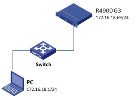
Using IPMItool software
1. Download the IPMItool tool that is compatible with Windows OS such as IPMItool v1.8.18 on the client. As a best practice, use IPMItool v1.8.18 or later versions.
2. Access Windows cmd.
Figure 3 Windows cmd
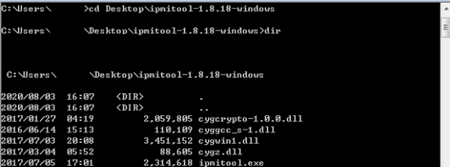
Using IPMItool to obtain chassis information
Execute the ipmitool -I lanplus -H 172.16.18.69 -U admin -P Password@_ chassis status command to obtain chassis status information.
Figure 4 Obtaining chassis status information