- Table of Contents
- Related Documents
-
| Title | Size | Download |
|---|---|---|
| 02-FRUs and compatibility matrixes | 16.88 MB |
Contents
2 FRUs and compatibility matrixes
CEPC-CQ8L/CEPC-CQ8LA/CEPC-CQ8L1A/CEPC-CQ8L3A
Configuration restrictions and guidelines
CSPEX-1104-E/CSPEX-1204/CSPEX-1304X/CSPEX-1404X/CSPEX-1504X/CSPEX-1504XA
CSPEX-1502X/CSPEX-1502XA/CSPEX-1602X/CSPEX-1602XA
CSPEX-1512X/CSPEX-1612X/CSPEX-1812X/CSPEX-1812X-E/CSPEX-1802X/CSPEX-1802XA
Configuration restrictions and guidelines
Configuration restrictions and guidelines
MIC-GT20L/MIC-GT20L1/MIC-GT20LA
NIC-CQ2L/NIC-CQ2LA/NIC-CQ2LA-G
NIC-GP24L1/NIC-GP24L1A/NIC-GP24L1A-G
NIC-XP20L1/NIC-XP20L1A/NIC-XP20L1A-G
Configuration restrictions and guidelines
IM modules (Universal line processing unit)
Configuration restrictions and guidelines
IM modules (Security monitor line processing unit)
IM modules (Network data encryption service processing unit)
IM modules (Universal open application platform)
Configuration restrictions and guidelines
CSFC-04-1/CSFC-04-2/CSFC-04-3/CSFC-04-4
CSFC-16T/CSFC-16T1/CSFC-16E/CSFC-16EA
Configuration restrictions and guidelines
Configuration restrictions and guidelines
CR16010-F (one fan tray) fan tray
CR16010-F (dual fan trays) fan tray
CR16010H-F/CR16010H-FA/CR16018-F/CR16018-FA fan trays
Configuration restrictions and guidelines
2 FRUs and compatibility matrixes
For compatibility between the cards and the software release, see the release notes.
For compatibility between the cards and transceiver modules, see the cards and transceiver modules compatibility matrixes for the device.
|
|
NOTE: · This document uses the identifier printed on a card or subcard as its model name. · All subcards except for the MIC-SM are hot swappable. |
MPUs
You can install one MPU, or two MPUs for redundancy for the router. To install two MPUs for the router, make sure they are the same model.
CSR05SRP1L1
View
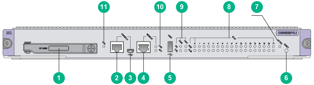
Figure2-1 CSR05SRP1L1 view
|
(1) CF card |
(2) Console port |
|
(3) USB console port |
(4) Management Ethernet port (10/100/1000Base-T) |
|
(5) USB 2.0 port |
(6) System reset button |
|
(7) MPU active/standby LED. For the LED description, see Table2-1. |
(8) Card status LEDs. For the LED description, see Table2-2. |
|
(9) Fan tray status LEDs. For the LED description, see Table2-3. |
(10) Management Ethernet port LED. For the LED description, see Table2-4. |
|
(11) CF card LED. For the LED description, see Table2-5. |
|
LEDs
Table2-1 MPU active/standby LED description
|
LED mark |
Status |
Description |
|
ACTIVE |
Steady green |
The MPU is in active state. |
|
Off |
The following are the possible causes: · The MPU is in standby state. · The MPU has failed. To identify the failure, see the card status LED description. |
Table2-2 Card status LED description
|
Status |
Description |
|
|
RUN (Green) |
ALM (Red) |
|
|
Flashing green (once every 2 seconds) |
Off |
The card in the corresponding slot is operating correctly. |
|
Fast flashing green (once every 4 seconds) |
Steady on |
The card in the corresponding slot is loading software. If the card keeps in this state, the software version running on the device is not compatible with the card. |
|
Flashing green (once every 2 seconds) |
Flashing red (once every 4 seconds) |
The temperature of the card in the corresponding slot is abnormal. The temperature has exceeded the upper warning temperature threshold or dropped below the lower temperature threshold. |
|
Steady on |
Steady on |
The card in the corresponding slot is starting or faulty. |
|
Off |
Off |
No card is available in the corresponding slot. |
|
|
NOTE: At the system startup, the ALM LED being on for a while does not mean that the card is faulty. |
Table2-3 Fan tray status LED description
|
Status |
Description |
|
|
OK (Green) |
FAIL (Red) |
|
|
Steady on |
Off |
The fan tray is operating correctly. |
|
Off |
Steady on |
One or more fans in the fan tray have failed or the fan tray is not in position. |
|
Off |
Off |
The router is not powered on. |
Table2-4 Management Ethernet port LED description
|
Status |
Description |
|
|
LINK (Green) |
ACT (yellow) |
|
|
Steady on |
Flashing green |
The port is in sending or receiving data. |
|
Steady on |
Off |
A link is present on the port. |
|
Off |
Off |
No link is present on the port. |
Table2-5 CF card LED description
|
LED |
Status |
Description |
|
CF card |
Steady green |
The CF card is present and idle. Do not hot swap it. |
|
Flashing green |
The CF card is present and the system is reading/writing the card. Do not hot swap it. |
|
|
Off |
The CF card is not in position, or the CF card is in offline state. You can hot swap it. |
Ports
Console port
The console port can be connected to a computer for system debugging, configuration, maintenance, management, and host software loading.
Table2-6 Console port specifications
|
Item |
Description |
|
Connector type |
RJ-45 |
|
Compliant standard |
Asynchronous EIA/TIA-232 |
|
Transmission baud rate |
≤ 115200 bps. The default value is 9600 bps. |
|
Transmission medium and max transmission distance |
Common asynchronous serial interface cable, with a maximum transmission distance of 15 m (49.21 ft) |
|
Services |
Connects to the serial port on a local PC running a terminal emulation program. |
USB console port
Table2-7 USB console port specifications
|
Item |
Description |
|
Connector type |
USB-AB |
|
Compliant standard |
USB 2.0, full speed |
|
Transmission baud rate |
≤ 115200 bps. The default value is 9600 bps. |
|
Transmission medium and max transmission distance |
USB-AB cable, with a maximum transmission distance of 2 m (6.56 ft) |
|
Services |
Connects to the USB port on a local PC running a terminal emulation program to provide a command-line interface for the router. A generic USB to serial port driver is required on the PC. Connects routers to PCs or similar terminals that do not have a serial port. |
Management Ethernet port
Connects to a computer for router program loading and router debugging, or connects to a remote NMS for remote management.
Table2-8 Management Ethernet port specifications
|
Item |
Description |
|
Connector type |
RJ-45 |
|
Port quantity |
1 |
|
Transmission baud rate |
10/100/1000 Mbps |
|
Transmission medium and max transmission distance |
Category-5 or above twisted pair cable, with a transmission distance of 100 m (328.08 ft) |
|
Services |
For router software upgrade and network management |
USB port
USB ports can connect multiple types of devices and provide a higher data transfer rate than common parallel interfaces and serial interfaces.
Table2-9 USB port specifications
|
Item |
Description |
|
Connector type |
USB A |
|
Compliant standard |
USB 2.0 |
|
Services |
External storage media |
|
|
NOTE: Extension cables are not supported. |
CF card slot
A CF card is a mobile storage device that features fast speed, large capacity, small size, light weight, and low power consumption.
Table2-10 External CF card specifications
|
Item |
Description |
|
CF card slots |
1 |
|
CF card capacity |
4 GB |
|
Services |
You can use a CF card to store logs, application program files, and configuration files. |
|
|
NOTE: Before you use a CF card, insert the CF card into the card slot and fasten the card cover. |
Technical specifications
Table2-11 Technical specifications
|
Item |
Description |
|
Dimensions (H × W × D) |
40 × 399 × 352 mm (1.57 × 15.71 × 13.86 in) |
|
Weight |
3.05 kg (6.72 lb) |
|
Maximum power consumption |
53 W |
|
Power consumption (with typical configuration) |
47 W |
|
Minimum power consumption |
46 W |
|
Operating temperature |
0°C to 45°C (32°F to 113°F) |
|
SDRAM |
8 GB or 16 GB (subject to the card specifications) |
CSR05SRP1L3
View
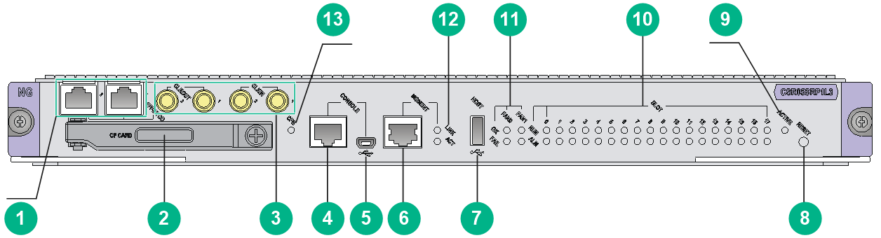
Figure2-2 CSR05SRP1L3 view
|
(1) High-precision time synchronization ports (Both are input ports by default. When both ports are input ports, only port 1 takes effect.) |
(2) CF card |
|
(3) SMB coaxial clock ports (2 input ports and 2 output ports) |
(4) Console port |
|
(5) USB console port |
(6) Management Ethernet ports (10/100/1000Base-T) |
|
(7) USB 2.0 port |
(8) System reset button |
|
(9) MPU active/standby LED. For the LED description, see Table2-12. |
(10) Card status LEDs. For the LED description, see Table2-13. |
|
(11) Fan tray status LEDs. For the LED description, see Table2-14. |
(12) Management Ethernet port LED. For the LED description, see Table2-15. |
|
(13) CF card LED. For the LED description, see Table2-16. |
|
LEDs
Table2-12 MPU active/standby LED description
|
LED mark |
Status |
Description |
|
ACTIVE |
Steady green |
The MPU is in active state. |
|
Off |
The following are the possible causes: · The MPU is in standby state. · The MPU has failed. To identify the failure, see the card status LED description. |
Table2-13 Card status LED description
|
Status |
Description |
|
|
RUN (Green) |
ALM (Red) |
|
|
Flashing green (once every 2 seconds) |
Off |
The card in the corresponding slot is operating correctly. |
|
Fast flashing green (once every 4 seconds) |
Steady on |
The card in the corresponding slot is loading software. If the card keeps in this state, the software version running on the device is not compatible with the card. |
|
Flashing green (once every 2 seconds) |
Flashing red (once every 4 seconds) |
The temperature of the card in the corresponding slot is abnormal. The temperature has exceeded the upper warning temperature threshold or dropped below the lower temperature threshold. |
|
Steady on |
Steady on |
The card in the corresponding slot is starting or faulty. |
|
Off |
Off |
No card is available in the corresponding slot. |
|
|
NOTE: At the system startup, the ALM LED being on for a while does not mean that the card is faulty. |
Table2-14 Fan tray status LED description
|
Status |
Description |
|
|
OK (Green) |
FAIL (Red) |
|
|
Steady on |
Off |
The fan tray is operating correctly. |
|
Off |
Steady on |
One or more fans in the fan tray have failed or the fan tray is not in position. |
|
Off |
Off |
The router is not powered on. |
Table2-15 Management Ethernet port LED description
|
Status |
Description |
|
|
LINK (Green) |
ACT (yellow) |
|
|
Steady on |
Flashing green |
The port is in sending or receiving data. |
|
Steady on |
Off |
A link is present on the port. |
|
Off |
Off |
No link is present on the port. |
Table2-16 CF card LED description
|
LED |
Status |
Description |
|
CF card |
Steady green |
The CF card is present and idle. Do not hot swap it. |
|
Flashing green |
The CF card is present and the system is reading/writing the card. Do not hot swap it. |
|
|
Off |
The CF card is not in position, or the CF card is in offline state. You can hot swap it. |
Ports
Console port
The console port can be connected to a computer for system debugging, configuration, maintenance, management, and host software loading.
Table2-17 Console port specifications
|
Item |
Description |
|
Connector type |
RJ-45 |
|
Compliant standard |
Asynchronous EIA/TIA-232 |
|
Transmission baud rate |
≤ 115200 bps. The default value is 9600 bps. |
|
Transmission medium and max transmission distance |
Common asynchronous serial interface cable, with a maximum transmission distance of 15 m (49.21 ft) |
|
Services |
Connects to the serial port on a local PC running a terminal emulation program. |
USB console port
Table2-18 USB console port specifications
|
Item |
Description |
|
Connector type |
USB-AB |
|
Compliant standard |
USB 2.0, full speed |
|
Transmission baud rate |
≤ 115200 bps. The default value is 9600 bps. |
|
Transmission medium and max transmission distance |
USB-AB cable, with a maximum transmission distance of 2 m (6.56 ft) |
|
Services |
Connects to the USB port on a local PC running a terminal emulation program to provide a command-line interface for the router. A generic USB to serial port driver is required on the PC. Connects routers to PCs or similar terminals that do not have a serial port. |
Management Ethernet port
Connects to a computer for router program loading and router debugging, or connects to a remote NMS for remote management.
Table2-19 Management Ethernet port specifications
|
Item |
Description |
|
Connector type |
RJ-45 |
|
Port quantity |
1 |
|
Transmission baud rate |
10/100/1000 Mbps |
|
Transmission medium and max transmission distance |
Category-5 or above twisted pair cable, with a transmission distance of 100 m (328.08 ft) |
|
Services |
For router software upgrade and network management |
USB port
USB ports can connect multiple types of devices and provide a higher data transfer rate than common parallel interfaces and serial interfaces.
Table2-20 USB port specifications
|
Item |
Description |
|
Connector type |
USB A |
|
Compliant standard |
USB 2.0 |
|
Services |
External storage media |
|
|
NOTE: Extension cables are not supported. |
CF card slot
A CF card is a mobile storage device that features fast speed, large capacity, small size, light weight, and low power consumption.
Table2-21 External CF card specifications
|
Item |
Description |
|
CF card slots |
1 |
|
CF card capacity |
4 GB |
|
Services |
You can use a CF card to store logs, application program files, and configuration files. |
|
|
NOTE: Before you use a CF card, insert the CF card into the card slot and fasten the card cover. |
SMB coaxial clock input/output port
SMB coaxial clock ports provide input or output clock references at 2.048 Mbps (2.048 MHz). You can set the data rate mode or frequency mode through the CLI. Two of them are input ports and two are output ports.
Table2-22 SMB coaxial clock input/output port specifications
|
Item |
Description |
|
Connector type |
SMB coaxial |
|
Compliant standard |
GJB681 |
|
Transmission baud rate |
2.048 Mbps |
|
Transmission medium |
75-ohm coaxial cable |
|
Services |
Sends and receives 2.048 MHz clocks and 2.048 Mbps signals to synchronize the clocks of the router and other devices, such as routers and the terminals. |
High-precision time synchronization port
Table2-23 High-precision time synchronization port specifications
|
Item |
Description |
|
Connector type |
RJ-45 |
|
Compliant standard |
QB-B-016-2010 |
|
Transmission baud rate |
9600 bps |
|
Transmission medium |
Category-5 or above twisted pair cable |
|
Services |
You can configure the port as an input port or output port at the CLI. Synchronizes the clocks of the router and other devices, such as GPS receivers and terminals. |
Technical specifications
Table2-24 Technical specifications
|
Item |
Description |
|
Dimensions (H × W × D) |
40 × 399 × 352 mm (1.57 × 15.71 × 13.86 in) |
|
Weight |
3.18 kg (7.01 lb) |
|
Maximum power consumption |
53 W |
|
Power consumption (with typical configuration) |
52 W |
|
Minimum power consumption |
50 W |
|
Operating temperature |
0°C to 45°C (32°F to 113°F) |
|
SDRAM |
8 GB or 16 GB (subject to the card specifications) |
CSR05SRP1P1
View
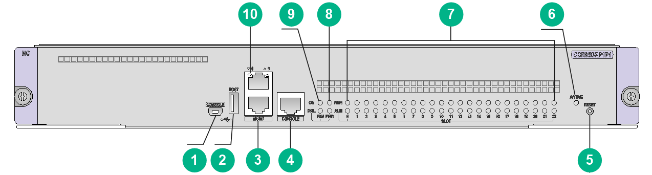
Figure2-3 CSR05SRP1P1 view
|
(1) USB console port |
(2) USB 2.0 port |
|
(3) Management Ethernet ports (10/100/1000Base-T) (port 1 reserved for future use) |
(4) Console port |
|
(5) System reset button |
(6) MPU active/standby LED. For the LED description, see Table2-25. |
|
(7) Card status LEDs. For the LED description, see Table2-26. |
(8) Power supply status LED. For the LED description, see Table2-27. |
|
(9) Fan tray status LED. For the LED description, see Table2-28. |
(10) Management Ethernet port LED. For the LED description, see Table2-29. |
LEDs
Table2-25 MPU active/standby LED description
|
LED mark |
Status |
Description |
|
ACTIVE |
Steady green |
The MPU is in active state. |
|
Off |
The following are the possible causes: · The MPU is in standby state. · The MPU has failed. To identify the failure, see the card status LED description. |
Table2-26 Card status LED description
|
Status |
Description |
|
|
RUN (Green) |
ALM (Red) |
|
|
Flashing green (once every 2 seconds) |
Off |
The card in the corresponding slot is operating correctly. |
|
Fast flashing green (once every 4 seconds) |
Steady on |
The card in the corresponding slot is loading software. If the card keeps in this state, the software version running on the device is not compatible with the card. |
|
Flashing green (once every 2 seconds) |
Flashing red (once every 4 seconds) |
The temperature of the card in the corresponding slot is abnormal. The temperature has exceeded the upper warning temperature threshold or dropped below the lower temperature threshold. |
|
Steady on |
Steady on |
The card in the corresponding slot is starting or faulty. |
|
Off |
Off |
No card is available in the corresponding slot. |
|
|
NOTE: At the system startup, the ALM LED being on for a while does not mean that the card is faulty. |
Table2-27 Power supply status LED description
|
Status |
Description |
|
|
OK (Green) |
FAIL (Red) |
|
|
Steady on |
Off |
All power supplies in the chassis are operating correctly. |
|
Off |
Steady on |
A power supply in the chassis does not have power output, because the power supply is faulty, the power supply is not powered on, the power cable is faulty, or the external power supply system has a power outage. |
|
Off |
Off |
The following are the possible causes: · No power supplies exist in the chassis. · No power supply in the chassis has power output, because the power supplies are faulty, the power supplies are not powered on, the power cables are faulty, or the external power supply system has a power outage. |
Table2-28 Fan tray status LED description
|
Status |
Description |
|
|
OK (Green) |
FAIL (Red) |
|
|
Steady on |
Off |
The fan tray is operating correctly. |
|
Off |
Steady on |
One or more fans in the fan tray have failed or the fan tray is not in position. |
|
Off |
Off |
The router is not powered on. |
Table2-29 Management Ethernet port LED description
|
LED mark |
Status |
Description |
|
LINK/ACT |
Flashing green |
The port is in sending or receiving data. |
|
Steady green |
A link is present on the port. |
|
|
Off |
No link is present on the port. |
Ports
Console port
The console port can be connected to a computer for system debugging, configuration, maintenance, management, and host software loading.
Table2-30 Console port specifications
|
Item |
Description |
|
Connector type |
RJ-45 |
|
Compliant standard |
Asynchronous EIA/TIA-232 |
|
Transmission baud rate |
≤ 115200 bps. The default value is 9600 bps. |
|
Transmission medium and max transmission distance |
Common asynchronous serial interface cable, with a maximum transmission distance of 15 m (49.21 ft) |
|
Services |
Connects to the serial port on a local PC running a terminal emulation program. |
USB console port
Table2-31 USB console port specifications
|
Item |
Description |
|
Connector type |
USB-AB |
|
Compliant standard |
USB 2.0, full speed |
|
Transmission baud rate |
≤ 115200 bps. The default value is 9600 bps. |
|
Transmission medium and max transmission distance |
USB-AB cable, with a maximum transmission distance of 2 m (6.56 ft) |
|
Services |
Connects to the USB port on a local PC running a terminal emulation program to provide a command-line interface for the router. A generic USB to serial port driver is required on the PC. Connects routers to PCs or similar terminals that do not have a serial port. |
Management Ethernet port
Connects to a computer for router program loading and router debugging, or connects to a remote NMS for remote management.
Table2-32 Management Ethernet port specifications
|
Item |
Description |
|
Connector type |
RJ-45 |
|
Port quantity |
2 (port 1 reserved for future use) |
|
Transmission baud rate |
10/100/1000 Mbps |
|
Transmission medium and max transmission distance |
Category-5 or above twisted pair cable, with a transmission distance of 100 m (328.08 ft) |
|
Services |
For router software upgrade and network management |
USB port
USB ports can connect multiple types of devices and provide a higher data transfer rate than common parallel interfaces and serial interfaces.
Table2-33 USB port specifications
|
Item |
Description |
|
Connector type |
USB A |
|
Compliant standard |
USB 2.0 |
|
Services |
External storage media |
|
|
NOTE: Extension cables are not supported. |
Technical specifications
Table2-34 Technical specifications
|
Item |
Description |
|
Dimensions (H × W × D) |
52.2 × 399 × 352 mm (2.06 × 15.71 × 13.86 in) |
|
Weight |
4.30 kg (9.48 lb) |
|
Maximum power consumption |
64 W |
|
Power consumption (with typical configuration) |
60 W |
|
Minimum power consumption |
58 W |
|
Operating temperature |
0°C to 45°C (32°F to 113°F) |
|
SDRAM |
8 GB |
CSR05SRP1P3/CSR05SRP1P3A
View
Figure2-4 CSR05SRP1P3 view
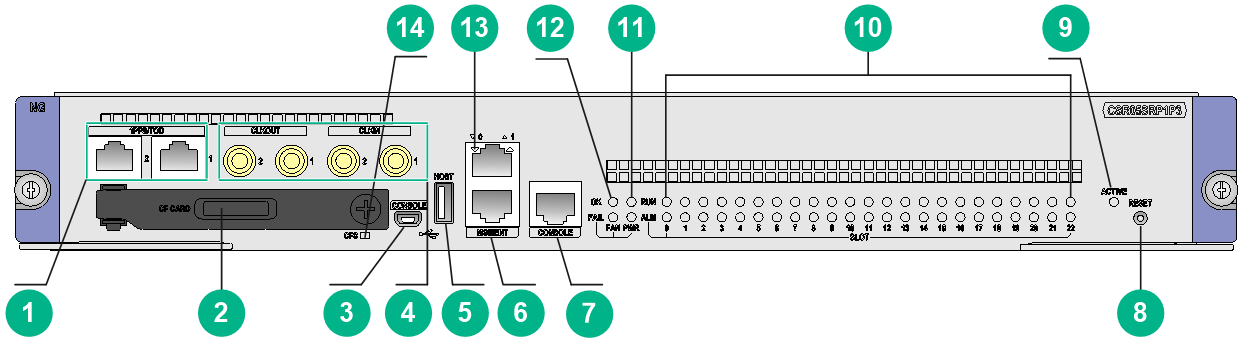
|
(1) High-precision time synchronization ports (Both are input ports by default. When both ports are input ports, only port 1 takes effect.) |
(2) CF card |
|
(3) USB console port |
(4) SMB coaxial clock ports (2 input ports and 2 output ports) |
|
(5) USB 2.0 port |
(6) Management Ethernet ports (10/100/1000Base-T) (port 1 reserved for future use) |
|
(7) Console port |
(8) System reset button |
|
(9) MPU active/standby LED. For the LED description, see Table2-35. |
(10) Card status LEDs. For the LED description, see Table2-36. |
|
(11) Power supply status LED. For the LED description, see Table2-37. |
(12) Fan tray status LED. For the LED description, see Table2-38. |
|
(13) Management Ethernet port LED. For the LED description, see Table2-39. |
(14) CF card LED. For the LED description, see Table2-40. |
The views of the CSR05SRP1P3 and CSR05SRP1P3A are similar. This figure uses the CSR05SRP1P3 as an example.
LEDs
Table2-35 MPU active/standby LED description
|
LED mark |
Status |
Description |
|
ACTIVE |
Steady green |
The MPU is in active state. |
|
Off |
The following are the possible causes: · The MPU is in standby state. · The MPU has failed. To identify the failure, see the card status LED description. |
Table2-36 Card status LED description
|
Status |
Description |
|
|
RUN (Green) |
ALM (Red) |
|
|
Flashing green (once every 2 seconds) |
Off |
The card in the corresponding slot is operating correctly. |
|
Fast flashing green (once every 4 seconds) |
Steady on |
The card in the corresponding slot is loading software. If the card keeps in this state, the software version running on the device is not compatible with the card. |
|
Flashing green (once every 2 seconds) |
Flashing red (once every 4 seconds) |
The temperature of the card in the corresponding slot is abnormal. The temperature has exceeded the upper warning temperature threshold or dropped below the lower temperature threshold. |
|
Steady on |
Steady on |
The card in the corresponding slot is starting or faulty. |
|
Off |
Off |
No card is available in the corresponding slot. |
|
|
NOTE: At the system startup, the ALM LED being on for a while does not mean that the card is faulty. |
Table2-37 Power supply status LED description
|
Status |
Description |
|
|
OK (Green) |
FAIL (Red) |
|
|
Steady on |
Off |
All power supplies in the chassis are operating correctly. |
|
Off |
Steady on |
A power supply in the chassis does not have power output, because the power supply is faulty, the power supply is not powered on, the power cable is faulty, or the external power supply system has a power outage. |
|
Off |
Off |
The following are the possible causes: No power supplies exist in the chassis. No power supply in the chassis has power output, because the power supplies are faulty, the power supplies are not powered on, the power cables are faulty, or the external power supply system has a power outage. |
Table2-38 Fan tray status LED description
|
Status |
Description |
|
|
OK (Green) |
FAIL (Red) |
|
|
Steady on |
Off |
The fan tray is operating correctly. |
|
Off |
Steady on |
One or more fans in the fan tray have failed or the fan tray is not in position. |
|
Off |
Off |
The router is not powered on. |
Table2-39 Management Ethernet port LED description
|
LED mark |
Status |
Description |
|
LINK/ACT |
Flashing green |
The port is in sending or receiving data. |
|
Steady green |
A link is present on the port. |
|
|
Off |
No link is present on the port. |
Table2-40 CF card LED description
|
LED |
Status |
Description |
|
CF card |
Steady green |
The CF card is present and idle. Do not hot swap it. |
|
Flashing green |
The CF card is present and the system is reading/writing the card. Do not hot swap it. |
|
|
Off |
The CF card is not in position, or the CF card is in offline state. You can hot swap it. |
Ports
Console port
The console port can be connected to a computer for system debugging, configuration, maintenance, management, and host software loading.
Table2-41 Console port specifications
|
Item |
Description |
|
Connector type |
RJ-45 |
|
Compliant standard |
Asynchronous EIA/TIA-232 |
|
Transmission baud rate |
≤ 115200 bps. The default value is 9600 bps. |
|
Transmission medium and max transmission distance |
Common asynchronous serial interface cable, with a maximum transmission distance of 15 m (49.21 ft) |
|
Services |
Connects to the serial port on a local PC running a terminal emulation program. |
USB console port
Table2-42 USB console port specifications
|
Item |
Description |
|
Connector type |
USB-AB |
|
Compliant standard |
USB 2.0, full speed |
|
Transmission baud rate |
≤ 115200 bps. The default value is 9600 bps. |
|
Transmission medium and max transmission distance |
USB-AB cable, with a maximum transmission distance of 2 m (6.56 ft) |
|
Services |
Connects to the USB port on a local PC running a terminal emulation program to provide a command-line interface for the router. A generic USB to serial port driver is required on the PC. Connects routers to PCs or similar terminals that do not have a serial port. |
Management Ethernet port
Connects to a computer for router program loading and router debugging, or connects to a remote NMS for remote management.
Table2-43 Management Ethernet port specifications
|
Item |
Description |
|
Connector type |
RJ-45 |
|
Port quantity |
2 (port 1 reserved for future use) |
|
Transmission baud rate |
10/100/1000 Mbps |
|
Transmission medium and max transmission distance |
Category-5 or above twisted pair cable, with a transmission distance of 100 m (328.08 ft) |
|
Services |
For router software upgrade and network management |
USB port
USB ports can connect multiple types of devices and provide a higher data transfer rate than common parallel interfaces and serial interfaces.
Table2-44 USB port specifications
|
Item |
Description |
|
Connector type |
USB A |
|
Compliant standard |
USB 2.0 |
|
Services |
External storage media |
|
|
NOTE: Extension cables are not supported. |
CF card slot
A CF card is a mobile storage device that features fast speed, large capacity, small size, light weight, and low power consumption.
Table2-45 External CF card specifications
|
Item |
Description |
|
CF card slots |
1 |
|
CF card capacity |
4 GB |
|
Services |
You can use a CF card to store logs, application program files, and configuration files. |
|
|
IMPORTANT: Before you use a CF card, insert the CF card into the card slot and fasten the card cover. |
SMB coaxial clock input/output port
SMB coaxial clock ports provide input or output clock references at 2.048 Mbps (2.048 MHz). You can set the data rate mode or frequency mode through the CLI. Two of them are input ports and two are output ports.
Table2-46 SMB coaxial clock input/output port specifications
|
Item |
Description |
|
Connector type |
SMB coaxial |
|
Compliant standard |
GJB681 |
|
Transmission baud rate |
2.048 Mbps |
|
Transmission medium |
75-ohm coaxial cable |
|
Services |
Sends and receives 2.048 MHz clocks and 2.048 Mbps signals to synchronize the clocks of the router and other devices, such as routers and the terminals. |
High-precision time synchronization port
Table2-47 High-precision time synchronization port specifications
|
Item |
Description |
|
Connector type |
RJ-45 |
|
Compliant standard |
QB-B-016-2010 |
|
Transmission baud rate |
9600 bps |
|
Transmission medium |
Category-5 or above twisted pair cable |
|
Services |
You can configure the port as an input port or output port at the CLI. Synchronizes the clocks of the router and other devices, such as GPS receivers and terminals. |
Technical specifications
Table2-48 CSR05SRP1P3/CSR05SRP1P3A MPU
|
Item |
Description |
|
Dimensions (H × W × D) |
52.2 × 399 × 352 mm (2.06 × 15.71 × 13.86 in) |
|
Weight |
CSR05SRP1P3: 4.80 kg (10.58 lb) CSR05SRP1P3A: 4.40kg (9.70 lb) |
|
Maximum power consumption |
64 W |
|
Power consumption (with typical configuration) |
60 W |
|
Minimum power consumption |
58 W |
|
Operating temperature |
0°C to 45°C (32°F to 113°F) |
|
SDRAM |
16 GB |
CSR05SRP1P3-G
View
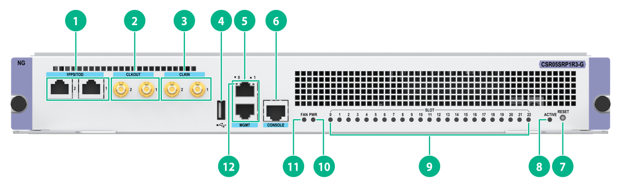
Figure2-5 CSR05SRP1P3-G view
|
(1) High-precision time synchronization ports (Both are input ports by default. When both ports are input ports, only port 1 takes effect.) |
(2) SMB coaxial clock ports (2 input ports and 2 output ports) |
|
(3) USB console port |
(4) USB 2.0 port |
|
(5) Management Ethernet ports (1000Base-T) |
(6) Console port |
|
(7) System reset button |
(8) MPU active/standby LED. For the LED description, see Table2-49. |
|
(9) Card status LEDs. For the LED description, see Table2-50. |
(10) Power supply status LED. For the LED description, see Table2-51. |
|
(11) Fan tray status LED. For the LED description, see Table2-52. |
(12) Management Ethernet port LED. For the LED description, see Table2-53. |
LEDs
Table2-49 MPU active/standby LED description
|
LED mark |
Status |
Description |
|
ACTIVE |
Steady green |
The MPU is in active state. |
|
Off |
The following are the possible causes: · The MPU is in standby state. · The MPU has failed. To identify the failure, see the card status LED description. |
Table2-50 Card status LED description
|
LED mark |
Status |
Description |
|
RUN/ALM |
Flashing green |
The card in the corresponding slot is operating correctly. |
|
Fast flashing green (4 Hz) |
The service module in the corresponding slot is loading software. If the card keeps in this state, the software version running on the device is not compatible with the card. |
|
|
Steady red |
The card in the corresponding slot is starting or faulty. |
|
|
Flashing red |
The temperature of the card in the corresponding slot is abnormal. The temperature has exceeded the upper warning temperature threshold or dropped below the lower temperature threshold. |
|
|
Off |
No card is available in the corresponding slot. |
Table2-51 Power supply status LED description
|
Power supply status LED |
Status |
Description |
|
PWR (Red or green) |
Green |
All power supplies in the chassis are operating correctly. |
|
Red |
A power supply in the chassis does not have power output, because the power supply is faulty, the power supply is not powered on, the power cable is faulty, or the external power supply system has a power outage. |
|
|
Off |
The following are the possible causes: · No power supplies exist in the chassis. · No power supply in the chassis has power output, because the power supplies are faulty, the power supplies are not powered on, the power cables are faulty, or the external power supply system has a power outage. |
Table2-52 Fan tray status LED description
|
Fan tray status LED |
Status |
Description |
|
FAN (Red or green) |
Green |
The fan tray is operating correctly. |
|
Red |
One or more fans in the fan tray have failed or the fan tray is not in position. |
|
|
Off |
The router is not powered on. |
Table2-53 Management Ethernet port LED description
|
LED mark |
Status |
Description |
|
LINK/ACT |
Flashing green |
The port is in sending or receiving data. |
|
Steady green |
A link is present on the port. |
|
|
Off |
No link is present on the port. |
Ports
Console port
The console port can be connected to a computer for system debugging, configuration, maintenance, management, and host software loading.
Table2-54 Console port specifications
|
Item |
Description |
|
Connector type |
RJ-45 |
|
Compliant standard |
Asynchronous EIA/TIA-232 |
|
Transmission baud rate |
≤ 115200 bps. The default value is 9600 bps. |
|
Transmission medium and max transmission distance |
Common asynchronous serial interface cable, with a maximum transmission distance of 15 m (49.21 ft) |
|
Services |
Connects to the serial port on a local PC running a terminal emulation program. |
USB console port
Table2-55 USB console port specifications
|
Item |
Description |
|
Connector type |
USB-AB |
|
Compliant standard |
USB 2.0, full speed |
|
Transmission baud rate |
≤ 115200 bps. The default value is 9600 bps. |
|
Transmission medium and max transmission distance |
USB-AB cable, with a maximum transmission distance of 2 m (6.56 ft) |
|
Services |
Connects to the USB port on a local PC running a terminal emulation program to provide a command-line interface for the router. A generic USB to serial port driver is required on the PC. Connects routers to PCs or similar terminals that do not have a serial port. |
Management Ethernet port
Connects to a computer for router program loading and router debugging, or connects to a remote NMS for remote management.
Table2-56 Management Ethernet port specifications
|
Item |
Description |
|
Connector type |
RJ-45 |
|
Port quantity |
2 |
|
Transmission baud rate |
1000 Mbps, full duplex |
|
Transmission medium and max transmission distance |
Category-5 or above twisted pair cable, with a transmission distance of 100 m (328.08 ft) |
|
Services |
For router software upgrade and network management |
USB port
USB ports can connect multiple types of devices and provide a higher data transfer rate than common parallel interfaces and serial interfaces.
Table2-57 USB port specifications
|
Item |
Description |
|
Connector type |
USB A |
|
Compliant standard |
USB 2.0 |
|
Services |
External storage media |
|
|
NOTE: Extension cables are not supported. |
SMB coaxial clock input/output port
SMB coaxial clock ports provide input or output clock references at 2.048 Mbps (2.048 MHz). You can set the data rate mode or frequency mode through the CLI. Two of them are input ports and two are output ports.
Table2-58 SMB coaxial clock input/output port specifications
|
Item |
Description |
|
Connector type |
SMB coaxial |
|
Compliant standard |
GJB681 |
|
Transmission baud rate |
2.048 Mbps |
|
Transmission medium |
75-ohm coaxial cable |
|
Services |
Sends and receives 2.048 MHz clocks and 2.048 Mbps signals to synchronize the clocks of the router and other devices, such as routers and the terminals. |
High-precision time synchronization port
Table2-59 High-precision time synchronization port specifications
|
Item |
Description |
|
Connector type |
RJ-45 |
|
Compliant standard |
QB-B-016-2010 |
|
Transmission baud rate |
9600 bps |
|
Transmission medium |
Category-5 or above twisted pair cable |
|
Services |
You can configure the port as an input port or output port at the CLI. Synchronizes the clocks of the router and other devices, such as GPS receivers and terminals. |
Technical specifications
Table2-60 Technical specifications
|
Item |
Description |
|
Dimensions (H × W × D) |
52.2 × 399 × 352 mm (2.06 × 15.71 × 13.86 in) |
|
Weight |
4.50 kg (9.92 lb) |
|
Maximum power consumption |
65W |
|
Power consumption (with typical configuration) |
50 W |
|
Minimum power consumption |
40 W |
|
Operating temperature |
0°C to 45°C (32°F to 113°F) |
|
SDRAM |
16 GB |
CSR05SRP1R3/CSR05SRP1R3A
View
Figure2-6 CSR05SRP1R3 view
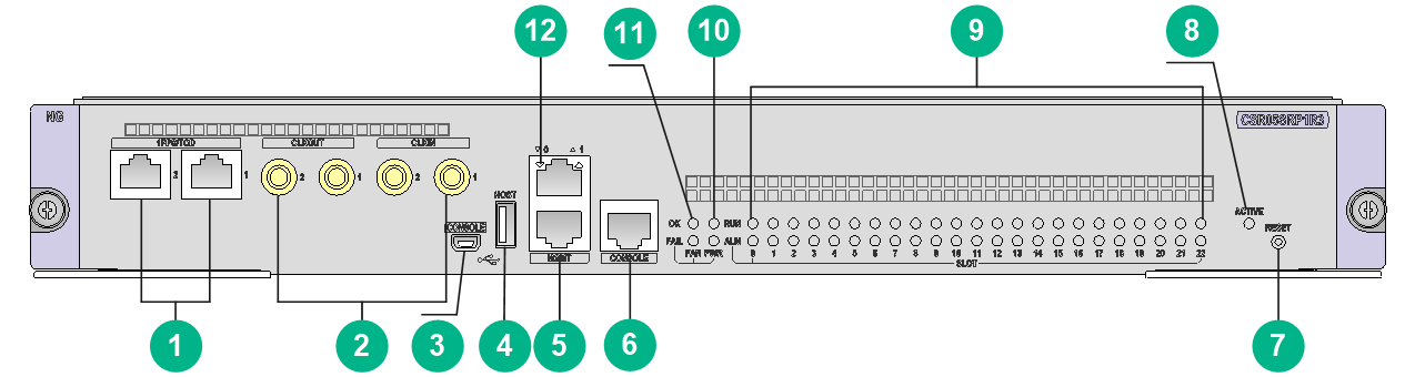
|
(1) High-precision time synchronization ports (Both are input ports by default. When both ports are input ports, only port 1 takes effect.) |
(2) SMB coaxial clock ports (2 input ports and 2 output ports) |
|
(3) USB console port |
(4) USB 2.0 port |
|
(5) Management Ethernet ports (1000Base-T) (port 1 reserved for future use) |
(6) Console port |
|
(7) System reset button |
(8) MPU active/standby LED. For the LED description, see Table2-61. |
|
(9) Card status LEDs. For the LED description, see Table2-62. |
(10) Power supply status LED. For the LED description, see Table2-63. |
|
(11) Fan tray status LED. For the LED description, see Table2-64. |
(12) Management Ethernet port LED. For the LED description, see Table2-65. |
The views of the CSR05SRP1R3 and CSR05SRP1R3A are similar. This figure uses the CSR05SRP1R3 as an example.
LEDs
Table2-61 MPU active/standby LED description
|
LED mark |
Status |
Description |
|
ACTIVE |
Steady green |
The MPU is in active state. |
|
Off |
The following are the possible causes: · The MPU is in standby state. · The MPU has failed. To identify the failure, see the card status LED description. |
Table2-62 Card status LED description
|
Status |
Description |
|
|
RUN (Green) |
ALM (Red) |
|
|
Flashing green (once every 2 seconds) |
Off |
The card in the corresponding slot is operating correctly. |
|
Fast flashing green (once every 4 seconds) |
Steady on |
The card in the corresponding slot is loading software. If the card keeps in this state, the software version running on the device is not compatible with the card. |
|
Flashing green (once every 2 seconds) |
Flashing red (once every 4 seconds) |
The temperature of the card in the corresponding slot is abnormal. The temperature has exceeded the upper warning temperature threshold or dropped below the lower temperature threshold. |
|
Steady on |
Steady on |
The card in the corresponding slot is starting or faulty. |
|
Off |
Off |
No card is available in the corresponding slot. |
|
|
NOTE: At the system startup, the ALM LED being on for a while does not mean that the card is faulty. |
Table2-63 Power supply status LED description
|
Status |
Description |
|
|
OK (Green) |
FAIL (Red) |
|
|
Steady on |
Off |
All power supplies in the chassis are operating correctly. |
|
Off |
Steady on |
A power supply in the chassis does not have power output, because the power supply is faulty, the power supply is not powered on, the power cable is faulty, or the external power supply system has a power outage. |
|
Off |
Off |
The following are the possible causes: No power supplies exist in the chassis. No power supply in the chassis has power output, because the power supplies are faulty, the power supplies are not powered on, the power cables are faulty, or the external power supply system has a power outage. |
Table2-64 Fan tray status LED description
|
Status |
Description |
|
|
OK (Green) |
FAIL (Red) |
|
|
Steady on |
Off |
The fan tray is operating correctly. |
|
Off |
Steady on |
One or more fans in the fan tray have failed or the fan tray is not in position. |
|
Off |
Off |
The router is not powered on. |
Table2-65 Management Ethernet port LED description
|
LED mark |
Status |
Description |
|
LINK/ACT |
Flashing green |
The port is in sending or receiving data. |
|
Steady green |
A link is present on the port. |
|
|
Off |
No link is present on the port. |
Ports
Console port
The console port can be connected to a computer for system debugging, configuration, maintenance, management, and host software loading.
Table2-66 Console port specifications
|
Item |
Description |
|
Connector type |
RJ-45 |
|
Compliant standard |
Asynchronous EIA/TIA-232 |
|
Transmission baud rate |
≤ 115200 bps. The default value is 9600 bps. |
|
Transmission medium and max transmission distance |
Common asynchronous serial interface cable, with a maximum transmission distance of 15 m (49.21 ft) |
|
Services |
Connects to the serial port on a local PC running a terminal emulation program. |
USB console port
Table2-67 USB console port specifications
|
Item |
Description |
|
Connector type |
USB-AB |
|
Compliant standard |
USB 2.0, full speed |
|
Transmission baud rate |
≤ 115200 bps. The default value is 9600 bps. |
|
Transmission medium and max transmission distance |
USB-AB cable, with a maximum transmission distance of 2 m (6.56 ft) |
|
Services |
Connects to the USB port on a local PC running a terminal emulation program to provide a command-line interface for the router. A generic USB to serial port driver is required on the PC. Connects routers to PCs or similar terminals that do not have a serial port. |
Management Ethernet port
Connects to a computer for router program loading and router debugging, or connects to a remote NMS for remote management.
Table2-68 Management Ethernet port specifications
|
Item |
Description |
|
Connector type |
RJ-45 |
|
Port quantity |
2 (port 1 reserved for future use) |
|
Transmission baud rate |
1000 Mbps, full duplex |
|
Transmission medium and max transmission distance |
Category-5 or above twisted pair cable, with a transmission distance of 100 m (328.08 ft) |
|
Services |
For router software upgrade and network management |
USB port
USB ports can connect multiple types of devices and provide a higher data transfer rate than common parallel interfaces and serial interfaces.
Table2-69 USB port specifications
|
Item |
Description |
|
Connector type |
USB A |
|
Compliant standard |
USB 2.0 |
|
Services |
External storage media |
|
|
NOTE: Extension cables are not supported. |
SMB coaxial clock input/output port
SMB coaxial clock ports provide input or output clock references at 2.048 Mbps (2.048 MHz). You can set the data rate mode or frequency mode through the CLI. Two of them are input ports and two are output ports.
Table2-70 SMB coaxial clock input/output port specifications
|
Item |
Description |
|
Connector type |
SMB coaxial |
|
Compliant standard |
GJB681 |
|
Transmission baud rate |
2.048 Mbps |
|
Transmission medium |
75-ohm coaxial cable |
|
Services |
Sends and receives 2.048 MHz clocks and 2.048 Mbps signals to synchronize the clocks of the router and other devices, such as routers and the terminals. |
High-precision time synchronization port
Table2-71 High-precision time synchronization port specifications
|
Item |
Description |
|
Connector type |
RJ-45 |
|
Compliant standard |
QB-B-016-2010 |
|
Transmission baud rate |
9600 bps |
|
Transmission medium |
Category-5 or above twisted pair cable |
|
Services |
You can configure the port as an input port or output port at the CLI. Synchronizes the clocks of the router and other devices, such as GPS receivers and terminals. |
Technical specifications
Table2-72 Technical specifications
|
Item |
Description |
|
Dimensions (H × W × D) |
52.2 × 399 × 352 mm (2.06 × 15.71 × 13.86 in) |
|
Weight |
4.90 kg (10.80 lb) |
|
Maximum power consumption |
130W |
|
Power consumption (with typical configuration) |
95W |
|
Minimum power consumption |
89W |
|
Operating temperature |
0°C to 45°C (32°F to 113°F) |
|
SDRAM |
2 × 16 GB |
CSR05SRP1R3-G/CSR05SRP1R3A-G
View
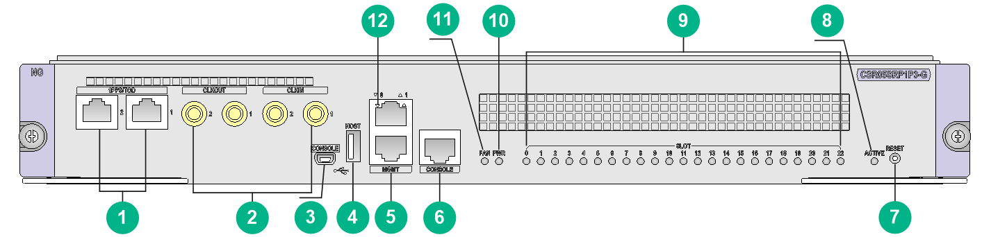
Figure2-7 CSR05SRP1R3-G view
|
(1) High-precision time synchronization ports (Both are input ports by default. When both ports are input ports, only port 1 takes effect.) |
(2) SMB coaxial clock output ports (2 in total) |
|
(3) SMB coaxial clock input ports (2 in total) |
(4) USB 2.0 port |
|
(5) Management Ethernet ports (1000Base-T) |
(6) Console port |
|
(7) System reset button |
(8) MPU active/standby LED. For the LED description, see Table2-73. |
|
(9) Card status LEDs. For the LED description, see Table2-74. |
(10) Power supply status LED. For the LED description, see Table2-75. |
|
(11) Fan tray status LED. For the LED description, see Table2-76. |
(12) Management Ethernet port LED. For the LED description, see Table2-77. |
The views of the CSR05SRP1R3-G and CSR05SRP1R3A-G are similar. This figure uses the CSR05SRP1R3-G as an example.
LEDs
Table2-73 MPU active/standby LED description
|
LED mark |
Status |
Description |
|
ACTIVE |
Steady green |
The MPU is in active state. |
|
Off |
The following are the possible causes: · The MPU is in standby state. · The MPU has failed. To identify the failure, see the card status LED description. |
Table2-74 Card status LED description
|
LED mark |
Status |
Description |
|
RUN/ALM |
Flashing green |
The card in the corresponding slot is operating correctly. |
|
Fast flashing green (4 Hz) |
The service module in the corresponding slot is loading software. If the card keeps in this state, the software version running on the device is not compatible with the card. |
|
|
Steady red |
The card in the corresponding slot is starting or faulty. |
|
|
Flashing red |
The temperature of the card in the corresponding slot is abnormal. The temperature has exceeded the upper warning temperature threshold or dropped below the lower temperature threshold. |
|
|
Off |
No card is available in the corresponding slot. |
Table2-75 Power supply status LED description
|
Power supply status LED |
Status |
Description |
|
PWR (Red or green) |
Steady green |
All power supplies in the chassis are operating correctly. |
|
Steady red |
A power supply in the chassis does not have power output, because the power supply is faulty, the power supply is not powered on, the power cable is faulty, or the external power supply system has a power outage. |
|
|
Off |
The following are the possible causes: · No power supplies exist in the chassis. · No power supply in the chassis has power output, because the power supplies are faulty, the power supplies are not powered on, the power cables are faulty, or the external power supply system has a power outage. |
Table2-76 Fan tray status LED description
|
Fan tray status LED |
Status |
Description |
|
FAN (Red or green) |
Steady green |
The fan tray is operating correctly. |
|
Steady red |
One or more fans in the fan tray have failed or the fan tray is not in position. |
|
|
Off |
The router is not powered on. |
Table2-77 Management Ethernet port LED description
|
LED mark |
Status |
Description |
|
LINK/ACT |
Flashing green |
The port is in sending or receiving data. |
|
Steady green |
A link is present on the port. |
|
|
Off |
No link is present on the port. |
Ports
Console port
The console port can be connected to a computer for system debugging, configuration, maintenance, management, and host software loading.
Table2-78 Console port specifications
|
Item |
Description |
|
Connector type |
RJ-45 |
|
Compliant standard |
Asynchronous EIA/TIA-232 |
|
Transmission baud rate |
≤ 115200 bps. The default value is 9600 bps. |
|
Transmission medium and max transmission distance |
Common asynchronous serial interface cable, with a maximum transmission distance of 15 m (49.21 ft) |
|
Services |
Connects to the serial port on a local PC running a terminal emulation program. |
Management Ethernet port
Connects to a computer for router program loading and router debugging, or connects to a remote NMS for remote management.
Table2-79 Management Ethernet port specifications
|
Item |
Description |
|
Connector type |
RJ-45 |
|
Port quantity |
2 |
|
Transmission baud rate |
1000 Mbps, full duplex |
|
Transmission medium and max transmission distance |
Category-5 or above twisted pair cable, with a transmission distance of 100 m (328.08 ft) |
|
Services |
For router software upgrade and network management |
USB port
USB ports can connect multiple types of devices and provide a higher data transfer rate than common parallel interfaces and serial interfaces.
Table2-80 USB port specifications
|
Item |
Description |
|
Connector type |
USB A |
|
Compliant standard |
USB 2.0 |
|
Services |
External storage media |
|
|
NOTE: Extension cables are not supported. |
SMB coaxial clock input/output port
SMB coaxial clock ports provide input or output clock references at 2.048 Mbps (2.048 MHz). You can set the data rate mode or frequency mode through the CLI. Two of them are input ports and two are output ports.
Table2-81 SMB coaxial clock input/output port specifications
|
Item |
Description |
|
Connector type |
SMB coaxial |
|
Compliant standard |
GJB681 |
|
Transmission baud rate |
2.048 Mbps |
|
Transmission medium |
75-ohm coaxial cable |
|
Services |
Sends and receives 2.048 MHz clocks and 2.048 Mbps signals to synchronize the clocks of the router and other devices, such as routers and the terminals. |
High-precision time synchronization port
Table2-82 High-precision time synchronization port specifications
|
Item |
Description |
|
Connector type |
RJ-45 |
|
Compliant standard |
QB-B-016-2010 |
|
Transmission baud rate |
9600 bps |
|
Transmission medium |
Category-5 or above twisted pair cable |
|
Services |
You can configure the port as an input port or output port at the CLI. Synchronizes the clocks of the router and other devices, such as GPS receivers and terminals. |
Technical specifications
Table2-83 Technical specifications
|
Item |
Description |
|
Dimensions (H × W × D) |
52.2 × 399 × 352 mm (2.06 × 15.71 × 13.86 in) |
|
Weight |
4.55 kg (10.03 lb) |
|
Maximum power consumption |
130 W |
|
Power consumption (with typical configuration) |
117 W |
|
Minimum power consumption |
55 W |
|
Operating temperature |
0°C to 45°C (32°F to 113°F) |
|
SDRAM |
16 GB or 32 GB (subject to the card specifications) |
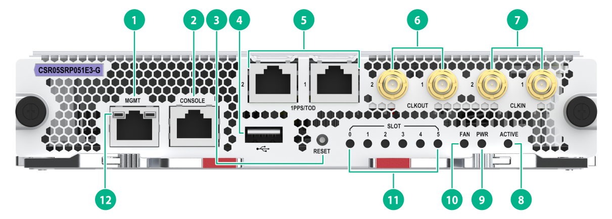
CSR05SRP051E3-G
View
Figure2-8 CSR05SRP051E3-G view
|
(1) Management Ethernet port (10/100/1000Base-T) |
(2) Console port |
|
(3) System reset button |
(4) USB 2.0 port |
|
(5) High-precision time synchronization ports (Both are input ports by default. When both ports are input ports, only port 1 takes effect.) |
(6) SMB coaxial clock output ports (2 in total) |
|
(7) SMB coaxial clock input ports (2 in total) |
(8) MPU active/standby LED. For the LED description, see Table2-84. |
|
(9) Power supply status LED. For the LED description, see Table2-85. |
(10) Fan tray status LED. For the LED description, see Table2-86. |
|
(11) Card status LEDs. For the LED description, see Table2-87. |
(12) Management Ethernet port LED. For the LED description, see Table2-88. |
LEDs
Table2-84 MPU active/standby LED description
|
LED mark |
Status |
Description |
|
ACTIVE |
Steady green |
The MPU is in active state. |
|
Off |
The following are the possible causes: · The MPU is in standby state. · The MPU has failed. To identify the failure, see the card status LED description. |
Table2-85 Power supply status LED description
|
Power supply status LED |
Status |
Description |
|
PWR (Red or green) |
Steady green |
All power supplies in the chassis are operating correctly. |
|
Steady red |
A power supply in the chassis does not have power output, because the power supply is faulty, the power supply is not powered on, the power cable is faulty, or the external power supply system has a power outage. |
|
|
Off |
The following are the possible causes: · No power supplies exist in the chassis. · No power supply in the chassis has power output, because the power supplies are faulty, the power supplies are not powered on, the power cables are faulty, or the external power supply system has a power outage. |
Table2-86 Fan tray status LED description
|
Fan tray status LED |
Status |
Description |
|
FAN (Red or green) |
Steady green |
The fan tray is operating correctly. |
|
Steady red |
One or more fans in the fan tray have failed or the fan tray is not in position. |
|
|
Off |
The router is not powered on. |
Table2-87 Card status LED description
|
LED mark |
Status |
Description |
|
RUN/ALM |
Flashing green |
The card in the corresponding slot is operating correctly. |
|
Fast flashing green (4 Hz) |
The service module in the corresponding slot is loading software. If the card keeps in this state, the software version running on the device is not compatible with the card. |
|
|
Steady red |
The card in the corresponding slot is starting or faulty. |
|
|
Flashing red |
The temperature of the card in the corresponding slot is abnormal. The temperature has exceeded the upper warning temperature threshold or dropped below the lower temperature threshold. |
|
|
Off |
No card is available in the corresponding slot. |
|
|
NOTE: At the system startup, the ALM LED being on for a while does not mean that the card is faulty. |
Table2-88 Management Ethernet port LED description
|
Status |
Description |
|
|
LINK (Green) |
ACT (yellow) |
|
|
Steady on |
Flashing |
A link is present, and the port is sending or receiving data. |
|
Steady on |
Off |
A link is present, but the port is not sending or receiving data. |
|
Off |
Off |
No link is present on the port. |
Ports
Management Ethernet port
Connects to a computer for router program loading and router debugging, or connects to a remote NMS for remote management.
Table2-89 Management Ethernet port specifications
|
Item |
Description |
|
Connector type |
RJ-45 |
|
Port quantity |
1 |
|
Transmission baud rate |
10/100/1000 Mbps |
|
Transmission medium and max transmission distance |
Category-5 or above twisted pair cable, with a transmission distance of 100 m (328.08 ft) |
|
Services |
For router software upgrade and network management |
Console port
The console port can be connected to a computer for system debugging, configuration, maintenance, management, and host software loading.
Table2-90 Console port specifications
|
Item |
Description |
|
Connector type |
RJ-45 |
|
Compliant standard |
Asynchronous EIA/TIA-232 |
|
Transmission baud rate |
≤ 115200 bps. The default value is 9600 bps. |
|
Transmission medium and max transmission distance |
Common asynchronous serial interface cable, with a maximum transmission distance of 15 m (49.21 ft) |
|
Services |
Connects to the serial port on a local PC running a terminal emulation program. |
USB port
USB ports can connect multiple types of devices and provide a higher data transfer rate than common parallel interfaces and serial interfaces.
Table2-91 USB port specifications
|
Item |
Description |
|
Connector type |
USB A |
|
Compliant standard |
USB 2.0 |
|
Services |
External storage media |
|
|
NOTE: Extension cables are not supported. |
High-precision time synchronization port
Table2-92 High-precision time synchronization port specifications
|
Item |
Description |
|
Connector type |
RJ-45 |
|
Compliant standard |
QB-B-016-2010 |
|
Transmission baud rate |
9600 bps |
|
Transmission medium |
Category-5 or above twisted pair cable |
|
Services |
You can configure the port as an input port or output port at the CLI. Synchronizes the clocks of the router and other devices, such as GPS receivers and terminals. |
SMB coaxial clock input/output port
SMB coaxial clock ports provide input or output clock references at 2.048 Mbps (2.048 MHz). You can set the data rate mode or frequency mode through the CLI. Two of them are input ports and two are output ports.
Table2-93 SMB coaxial clock input/output port specifications
|
Item |
Description |
|
Connector type |
SMB coaxial |
|
Compliant standard |
GJB681 |
|
Transmission baud rate |
2.048 Mbps |
|
Transmission medium |
75-ohm coaxial cable |
|
Services |
Sends and receives 2.048 MHz clocks and 2.048 Mbps signals to synchronize the clocks of the router and other devices, such as routers and the terminals. |
Technical specifications
Table2-94 Technical specifications
|
Item |
Description |
|
Dimensions (H × W × D) |
38.9 × 199 × 353 mm (1.53 × 7.83 × 13.90 in) |
|
Weight |
2.45 kg (5.40 lb) |
|
Maximum power consumption |
120 W |
|
Power consumption (with typical configuration) |
100 W |
|
Minimum power consumption |
94 W |
|
Operating temperature |
0°C to 45°C (32°F to 113°F) |
|
SDRAM |
16 GB or 32 GB (subject to the card specifications) |
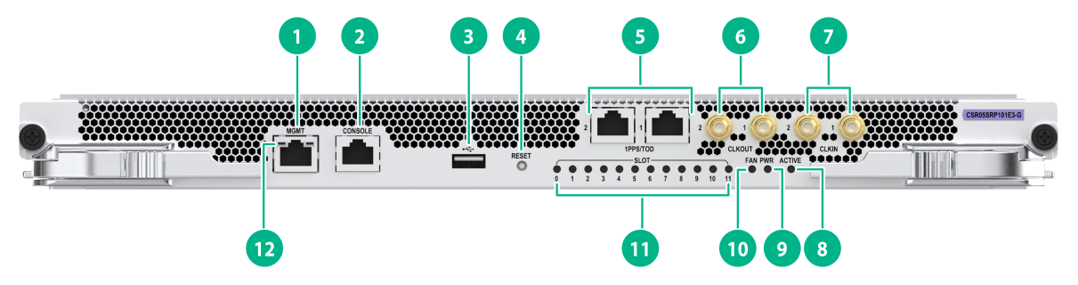
CSR05SRP101E3-G
View
Figure2-9 CSR05SRP101E3-G view
|
(1) Management Ethernet port (10/100/1000Base-T) |
(2) Console port |
|
(3) USB 2.0 port |
(4) System reset button |
|
(5) High-precision time synchronization ports (Both are input ports by default. When both ports are input ports, only port 1 takes effect.) |
(6) SMB coaxial clock output ports (2 in total) |
|
(7) SMB coaxial clock input ports (2 in total) |
(8) MPU active/standby LED. For the LED description, see Table2-95. |
|
(9) Power supply status LED. For the LED description, see Table2-96. |
(10) Fan tray status LED. For the LED description, see Table2-97. |
|
(11) Card status LEDs. For the LED description, see Table2-98. |
(12) Management Ethernet port LED. For the LED description, see Table2-99. |
LEDs
Table2-95 MPU active/standby LED description
|
LED mark |
Status |
Description |
|
ACTIVE |
Steady green |
The MPU is in active state. |
|
Off |
The following are the possible causes: · The MPU is in standby state. · The MPU has failed. To identify the failure, see the card status LED description. |
Table2-96 Power supply status LED description
|
Power supply status LED |
Status |
Description |
|
PWR (Red or green) |
Steady green |
All power supplies in the chassis are operating correctly. |
|
Steady red |
A power supply in the chassis does not have power output, because the power supply is faulty, the power supply is not powered on, the power cable is faulty, or the external power supply system has a power outage. |
|
|
Off |
The following are the possible causes: · No power supplies exist in the chassis. · No power supply in the chassis has power output, because the power supplies are faulty, the power supplies are not powered on, the power cables are faulty, or the external power supply system has a power outage. |
Table2-97 Fan tray status LED description
|
Fan tray status LED |
Status |
Description |
|
FAN (Red or green) |
Steady green |
The fan tray is operating correctly. |
|
Steady red |
One or more fans in the fan tray have failed or the fan tray is not in position. |
|
|
Off |
The router is not powered on. |
Table2-98 Card status LED description
|
LED mark |
Status |
Description |
|
RUN/ALM |
Flashing green |
The card in the corresponding slot is operating correctly. |
|
Fast flashing green (4 Hz) |
The service module in the corresponding slot is loading software. If the card keeps in this state, the software version running on the device is not compatible with the card. |
|
|
Steady red |
The card in the corresponding slot is starting or faulty. |
|
|
Flashing red |
The temperature of the card in the corresponding slot is abnormal. The temperature has exceeded the upper warning temperature threshold or dropped below the lower temperature threshold. |
|
|
Off |
No card is available in the corresponding slot. |
|
|
NOTE: At the system startup, the ALM LED being on for a while does not mean that the card is faulty. |
Table2-99 Management Ethernet port LED description
|
Status |
Description |
|
|
LINK (Green) |
ACT (yellow) |
|
|
Steady on |
Flashing |
A link is present, and the port is sending or receiving data. |
|
Steady on |
Off |
A link is present, but the port is not sending or receiving data. |
|
Off |
Off |
No link is present on the port. |
Ports
Management Ethernet port
Connects to a computer for router program loading and router debugging, or connects to a remote NMS for remote management.
Table2-100 Management Ethernet port specifications
|
Item |
Description |
|
Connector type |
RJ-45 |
|
Port quantity |
1 |
|
Transmission baud rate |
10/100/1000 Mbps |
|
Transmission medium and max transmission distance |
Category-5 or above twisted pair cable, with a transmission distance of 100 m (328.08 ft) |
|
Services |
For router software upgrade and network management |
Console port
The console port can be connected to a computer for system debugging, configuration, maintenance, management, and host software loading.
Table2-101 Console port specifications
|
Item |
Description |
|
Connector type |
RJ-45 |
|
Compliant standard |
Asynchronous EIA/TIA-232 |
|
Transmission baud rate |
≤ 115200 bps. The default value is 9600 bps. |
|
Transmission medium and max transmission distance |
Common asynchronous serial interface cable, with a maximum transmission distance of 15 m (49.21 ft) |
|
Services |
Connects to the serial port on a local PC running a terminal emulation program. |
USB port
USB ports can connect multiple types of devices and provide a higher data transfer rate than common parallel interfaces and serial interfaces.
Table2-102 USB port specifications
|
Item |
Description |
|
Connector type |
USB A |
|
Compliant standard |
USB 2.0 |
|
Services |
External storage media |
|
|
NOTE: Extension cables are not supported. |
High-precision time synchronization port
Table2-103 High-precision time synchronization port specifications
|
Item |
Description |
|
Connector type |
RJ-45 |
|
Compliant standard |
QB-B-016-2010 |
|
Transmission baud rate |
9600 bps |
|
Transmission medium |
Category-5 or above twisted pair cable |
|
Services |
You can configure the port as an input port or output port at the CLI. Synchronizes the clocks of the router and other devices, such as GPS receivers and terminals. |
SMB coaxial clock input/output port
SMB coaxial clock ports provide input or output clock references at 2.048 Mbps (2.048 MHz). You can set the data rate mode or frequency mode through the CLI. Two of them are input ports and two are output ports.
Table2-104 SMB coaxial clock input/output port specifications
|
Item |
Description |
|
Connector type |
SMB coaxial |
|
Compliant standard |
GJB681 |
|
Transmission baud rate |
2.048 Mbps |
|
Transmission medium |
75-ohm coaxial cable |
|
Services |
Sends and receives 2.048 MHz clocks and 2.048 Mbps signals to synchronize the clocks of the router and other devices, such as routers and the terminals. |
Technical specifications
Table2-105 Technical specifications
|
Item |
Description |
|
Dimensions (H × W × D) |
35 × 399 × 355 mm (1.38 × 15.71 × 13.98 in) |
|
Weight |
4.70 kg (10.36 lb) |
|
Maximum power consumption |
106 W |
|
Power consumption (with typical configuration) |
98 W |
|
Minimum power consumption |
95 W |
|
Operating temperature |
0°C to 45°C (32°F to 113°F) |
|
SDRAM |
16 GB or 32 GB (subject to the card specifications) |
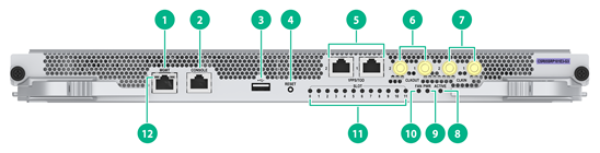
CSR05SRP101E3-G3
View
Figure2-10 CSR05SRP101E3-G3 view
|
(1) Management Ethernet port (10/100/1000Base-T) |
(2) Console port |
|
(3) USB 2.0 port |
(4) System reset button |
|
(5) High-precision time synchronization ports (Both are input ports by default. When both ports are input ports, only port 1 takes effect.) |
(6) SMB coaxial clock output ports (2 in total) |
|
(7) SMB coaxial clock input ports (2 in total) |
(8) MPU active/standby LED. For the LED description, see Table2-106. |
|
(9) Power supply status LED. For the LED description, see Table2-107. |
(10) Fan tray status LED. For the LED description, see Table2-108. |
|
(11) Card status LEDs. For the LED description, see Table2-109. |
(12) Management Ethernet port LED. For the LED description, see Table2-110. |
LEDs
Table2-106 MPU active/standby LED description
|
LED mark |
Status |
Description |
|
ACTIVE |
Steady green |
The MPU is in active state. |
|
Off |
The following are the possible causes: · The MPU is in standby state. · The MPU has failed. To identify the failure, see the card status LED description. |
Table2-107 Power supply status LED description
|
Power supply status LED |
Status |
Description |
|
PWR (Red or green) |
Steady green |
All power supplies in the chassis are operating correctly. |
|
Steady red |
A power supply in the chassis does not have power output, because the power supply is faulty, the power supply is not powered on, the power cable is faulty, or the external power supply system has a power outage. |
|
|
Off |
The following are the possible causes: · No power supplies exist in the chassis. · No power supply in the chassis has power output, because the power supplies are faulty, the power supplies are not powered on, the power cables are faulty, or the external power supply system has a power outage. |
Table2-108 Fan tray status LED description
|
Fan tray status LED |
Status |
Description |
|
FAN (Red or green) |
Steady green |
The fan tray is operating correctly. |
|
Steady red |
One or more fans in the fan tray have failed or the fan tray is not in position. |
|
|
Off |
The router is not powered on. |
Table2-109 Card status LED description
|
LED mark |
Status |
Description |
|
RUN/ALM |
Flashing green |
The card in the corresponding slot is operating correctly. |
|
Fast flashing green (4 Hz) |
The service module in the corresponding slot is loading software. If the card keeps in this state, the software version running on the device is not compatible with the card. |
|
|
Steady red |
The card in the corresponding slot is starting or faulty. |
|
|
Flashing red |
The temperature of the card in the corresponding slot is abnormal. The temperature has exceeded the upper warning temperature threshold or dropped below the lower temperature threshold. |
|
|
Off |
No card is available in the corresponding slot. |
|
|
NOTE: At the system startup, the ALM LED being on for a while does not mean that the card is faulty. |
Table2-110 Management Ethernet port LED description
|
Status |
Description |
|
|
LINK (Green) |
ACT (yellow) |
|
|
Steady on |
Flashing |
A link is present, and the port is sending or receiving data. |
|
Steady on |
Off |
A link is present, but the port is not sending or receiving data. |
|
Off |
Off |
No link is present on the port. |
Ports
Management Ethernet port
Connects to a computer for router program loading and router debugging, or connects to a remote NMS for remote management.
Table2-111 Management Ethernet port specifications
|
Item |
Description |
|
Connector type |
RJ-45 |
|
Port quantity |
1 |
|
Transmission baud rate |
10/100/1000 Mbps |
|
Transmission medium and max transmission distance |
Category-5 or above twisted pair cable, with a transmission distance of 100 m (328.08 ft) |
|
Services |
For router software upgrade and network management |
Console port
The console port can be connected to a computer for system debugging, configuration, maintenance, management, and host software loading.
Table2-112 Console port specifications
|
Item |
Description |
|
Connector type |
RJ-45 |
|
Compliant standard |
Asynchronous EIA/TIA-232 |
|
Transmission baud rate |
≤ 115200 bps. The default value is 9600 bps. |
|
Transmission medium and max transmission distance |
Common asynchronous serial interface cable, with a maximum transmission distance of 15 m (49.21 ft) |
|
Services |
Connects to the serial port on a local PC running a terminal emulation program. |
USB port
USB ports can connect multiple types of devices and provide a higher data transfer rate than common parallel interfaces and serial interfaces.
Table2-113 USB port specifications
|
Item |
Description |
|
Connector type |
USB A |
|
Compliant standard |
USB 2.0 |
|
Services |
External storage media |
|
|
NOTE: Extension cables are not supported. |
High-precision time synchronization port
Table2-114 High-precision time synchronization port specifications
|
Item |
Description |
|
Connector type |
RJ-45 |
|
Compliant standard |
QB-B-016-2010 |
|
Transmission baud rate |
9600 bps |
|
Transmission medium |
Category-5 or above twisted pair cable |
|
Services |
You can configure the port as an input port or output port at the CLI. Synchronizes the clocks of the router and other devices, such as GPS receivers and terminals. |
SMB coaxial clock input/output port
SMB coaxial clock ports provide input or output clock references at 2.048 Mbps (2.048 MHz). You can set the data rate mode or frequency mode through the CLI. Two of them are input ports and two are output ports.
Table2-115 SMB coaxial clock input/output port specifications
|
Item |
Description |
|
Connector type |
SMB coaxial |
|
Compliant standard |
GJB681 |
|
Transmission baud rate |
2.048 Mbps |
|
Transmission medium |
75-ohm coaxial cable |
|
Services |
Sends and receives 2.048 MHz clocks and 2.048 Mbps signals to synchronize the clocks of the router and other devices, such as routers and the terminals. |
Technical specifications
Table2-116 Technical specifications
|
Item |
Description |
|
Dimensions (H × W × D) |
35 × 399 × 355 mm (1.38 × 15.71 × 13.98 in) |
|
Weight |
4.70 kg (10.36 lb) |
|
Maximum power consumption |
160 W |
|
Power consumption (with typical configuration) |
105 W |
|
Minimum power consumption |
97 W |
|
Operating temperature |
0°C to 45°C (32°F to 113°F) |
|
SDRAM |
16 GB or 32 GB (subject to the card specifications) |
Compatibility information
Table2-117 Compatibility matrix between MPUs and routers
|
Card model |
Applicable router models |
|
CSR05SRP1L1 |
CR16006-F, CR16010-F, CR16014-F |
|
CSR05SRP1L3 |
CR16006-F, CR16010-F, CR16014-F |
|
CSR05SRP1P1 |
CR16010H-F, CR16018-F |
|
CSR05SRP1P3 |
CR16010H-F, CR16018-F |
|
CSR05SRP1P3A |
CR16010H-FA, CR16018-FA |
|
CSR05SRP1P3-G |
CR16010H-F, CR16018-F |
|
CSR05SRP1R3 |
CR16010H-F, CR16018-F |
|
CSR05SRP1R3A |
CR16010H-FA, CR16018-FA |
|
CSR05SRP1R3-G |
CR16010H-F, CR16018-F |
|
CSR05SRP1R3A-G |
CR16010H-FA, CR16018-FA |
|
CSR05SRP051E3-G |
CR16003E-F, CR16005E-F |
|
CSR05SRP101E3-G |
CR16010E-F |
|
CSR05SRP101E3-G3 |
CR16010E-F |
CSPC LPUs
A combo interface is a logical interface that contains an SFP port and an RJ-45 Ethernet port. Only one of them can be activated at a time.
CSPC-CP1LCX
View
Figure2-11 CSPC-CP1LCX view
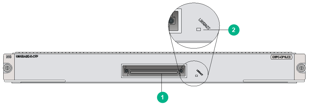
|
(1) 100GBASE-R-CFP fiber port (1 in total) |
(2) CFP port LED. For the LED description, see Table2-118. |
LEDs
Table2-118 CFP port LED description
|
LED |
Status |
Description |
|
CFP port LED |
Flashing |
The CFP port is sending or receiving data. |
|
Steady on |
A link is present on the CFP port. |
|
|
Off |
No link is present on the CFP port. |
Ports
Table2-119 Port specifications
|
Card model |
Description |
Connector type |
Port quantity |
Port transmission speed |
|
CSPC-CP1LCX |
1-port 100GE optical interface module |
LC |
1 |
100 Gbps |
Technical specifications
Table2-120 Technical specifications
|
Item |
Description |
|
Dimensions (H × W × D) |
40 × 399 × 352 mm (1.57 × 15.71 × 13.86 in) |
|
Weight |
3.50 kg (7.72 lb) |
|
Maximum power consumption |
173 W |
|
Power consumption (with typical configuration) |
156 W |
|
Minimum power consumption |
115 W |
|
Operating temperature |
0°C to 45°C (32°F to 113°F) |
CSPC-CP2LB
View
Figure2-12 CSPC-CP2LB view
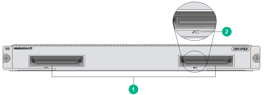
|
(1) 100GBASE-R-CFP fiber ports (2 in total) |
(2) CFP port LED. For the LED description, see Table2-121. |
LEDs
Table2-121 CFP port LED description
|
LED |
Status |
Description |
|
CFP port LED |
Flashing |
The CFP port is sending or receiving data. |
|
Steady on |
A link is present on the CFP port. |
|
|
Off |
No link is present on the CFP port. |
Ports
Table2-122 Port specifications
|
Card model |
Description |
Connector type |
Port quantity |
Port transmission speed |
|
CSPC-CP2LB |
2-port 100GE optical interface module |
LC |
2 |
100 Gbps |
Technical specifications
Table2-123 Technical specifications
|
Item |
Description |
|
Dimensions (H × W × D) |
40 × 399 × 352 mm (1.57 × 15.71 × 13.86 in) |
|
Weight |
4.06 kg (8.95 lb) |
|
Maximum power consumption |
197 W |
|
Power consumption (with typical configuration) |
178 W |
|
Minimum power consumption |
150 W |
|
Operating temperature |
0°C to 45°C (32°F to 113°F) |
CSPC-GE16XP4L-E
View
Figure2-13 CSPC-GE16XP4L-E view
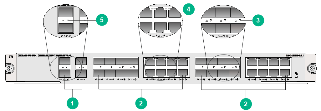
|
(1) 10GBASE-R-SFP+ fiber ports (4 in total) (10GE SFP+ modules supported) |
(2) Combo interfaces (16 in total) (10GE SFP+ modules supported in 1000BASE-X-SFP fiber ports) |
|
(3) SFP port LED. For the LED description, see Table2-125. |
(4) RJ-45 Ethernet Interface LED. For the LED description, see Table2-124. |
|
(5) SFP+ port LED. For the LED description, see Table2-126. |
|
LEDs
Table2-124 RJ-45 Ethernet port LED description
|
LED |
Status |
Description |
|
RJ-45 Ethernet port LED |
Flashing |
The port is sending or receiving data. |
|
Steady on |
A link is present on the port. |
|
|
Off |
No link is present on the port. |
Table2-125 SFP port LED description
|
LED |
Status |
Description |
|
SFP port LED |
Flashing |
The port is sending or receiving data. |
|
Steady on |
A link is present on the port. |
|
|
Off |
No link is present on the port. |
Table2-126 SFP+ port LED description
|
LED |
Status |
Description |
|
SFP+ port LED |
Flashing |
The port is sending or receiving data. |
|
Steady on |
A link is present on the port. |
|
|
Off |
No link is present on the port. |
|
|
NOTE: You can identify the speed of an SFP+ port by observing the color of its LED. Green indicates a speed of 10 Gbps, and yellow indicates a speed of 1000 Mbps. |
Ports
Table2-127 Port specifications
|
Card model |
Description |
Connector type |
Port quantity |
Port transmission speed |
|
CSPC-GE16XP4L-E |
16-port GE combo interface + 4-port 10GE optical interface module |
RJ-45 |
16 |
10/100/1000 Mbps |
|
LC |
16 |
1000 Mbps |
||
|
4 |
10 Gbps |
Technical specifications
Table2-128 Technical specifications
|
Item |
Description |
|
Dimensions (H × W × D) |
40 × 399 × 352 mm (1.57 × 15.71 × 13.86 in) |
|
Weight |
4.35 kg (9.59 lb) |
|
Maximum power consumption |
127 W |
|
Power consumption (with typical configuration) |
114 W |
|
Minimum power consumption |
107 W |
|
Operating temperature |
0°C to 45°C (32°F to 113°F) |
CSPC-GE24L-E
View
Figure2-14 CSPC-GE24L-E view
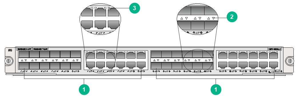
|
(1) Combo interfaces (24 in total) (10GE SFP+ modules supported in 1000BASE-X-SFP fiber ports) |
(2) SFP port LED. For the LED description, see Table2-130. |
|
(3) RJ-45 Ethernet Interface LED. For the LED description, see Table2-129. |
|
LEDs
Table2-129 RJ-45 Ethernet port LED description
|
LED |
Status |
Description |
|
RJ-45 Ethernet port LED |
Flashing |
The port is sending or receiving data. |
|
Steady on |
A link is present on the port. |
|
|
Off |
No link is present on the port. |
Table2-130 SFP port LED description
|
LED |
Status |
Description |
|
SFP port LED |
Flashing |
The port is sending or receiving data. |
|
Steady on |
A link is present on the port. |
|
|
Off |
No link is present on the port. |
Ports
Table2-131 Port specifications
|
Card model |
Description |
Connector type |
Port quantity |
Port transmission speed |
|
CSPC-GE24L-E |
24-port GE Combo interface service module |
RJ-45 |
24 |
10/100/1000 Mbps |
|
LC |
24 |
1000 Mbps |
Technical specifications
Table2-132 Technical specifications
|
Item |
Description |
|
Dimensions (H × W × D) |
40 × 399 × 352 mm (1.57 × 15.71 × 13.86 in) |
|
Weight |
4.45 kg (9.81 lb) |
|
Maximum power consumption |
114 W |
|
Power consumption (with typical configuration) |
110 W |
|
Minimum power consumption |
108 W |
|
Operating temperature |
0°C to 45°C (32°F to 113°F) |
CSPC-GP24GE8XP2L-E
View
Figure2-15 CSPC-GP24GE8XP2L-E view
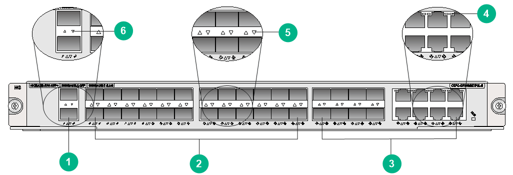
|
(1) 10GBASE-R-SFP+ fiber ports (2 in total) (10GE SFP+ modules supported) |
(2) 1000BASE-X-SFP fiber ports (24 in total) (GE SFP modules supported) |
|
(3) Combo interfaces (8 in total) (10GE SFP+ modules supported in 1000BASE-X-SFP fiber ports) |
(4) RJ-45 Ethernet Interface LED. For the LED description, see Table2-133. |
|
(5) SFP port LED. For the LED description, see Table2-134. |
(6) SFP+ port LED. For the LED description, see Table2-135. |
LEDs
Table2-133 RJ-45 Ethernet port LED description
|
LED |
Status |
Description |
|
RJ-45 Ethernet port LED |
Flashing |
The port is sending or receiving data. |
|
Steady on |
A link is present on the port. |
|
|
Off |
No link is present on the port. |
Table2-134 SFP port LED description
|
LED |
Status |
Description |
|
SFP port LED |
Flashing |
The port is sending or receiving data. |
|
Steady on |
A link is present on the port. |
|
|
Off |
No link is present on the port. |
Table2-135 SFP+ port LED description
|
LED |
Status |
Description |
|
SFP+ port LED |
Flashing |
The port is sending or receiving data. |
|
Steady on |
A link is present on the port. |
|
|
Off |
No link is present on the port. |
|
|
NOTE: You can identify the speed of an SFP+ port by observing the color of its LED. Green indicates a speed of 10 Gbps, and yellow indicates a speed of 1000 Mbps. |
Ports
Table2-136 Port specifications
|
Card model |
Description |
Connector type |
Port quantity |
Port transmission speed |
|
CSPC-GP24GE8XP2L-E |
24-port 1000BASE-X Ethernet optical interface (SFP, LC) + 8-port 1000BASE-X Ethernet combo interface + 2-port 10GBASE-R/W Ethernet optical interface line processing unit (SFP+, LC) (E Type) |
RJ45 |
8 |
10/100/1000 Mbps |
|
LC |
32 |
1000 Mbps |
||
|
2 |
10 Gbps |
Technical specifications
Table2-137 Technical specifications
|
Item |
Description |
|
Dimensions (H × W × D) |
40 × 399 × 352 mm (1.57 × 15.71 × 13.86 in) |
|
Weight |
4.45 kg (9.81 lb) |
|
Maximum power consumption |
126 W |
|
Power consumption (with typical configuration) |
113 W |
|
Minimum power consumption |
101 W |
|
Operating temperature |
0°C to 45°C (32°F to 113°F) |
CSPC-GP24LA1
View
Figure2-16 CSPC-GP24LA1 view
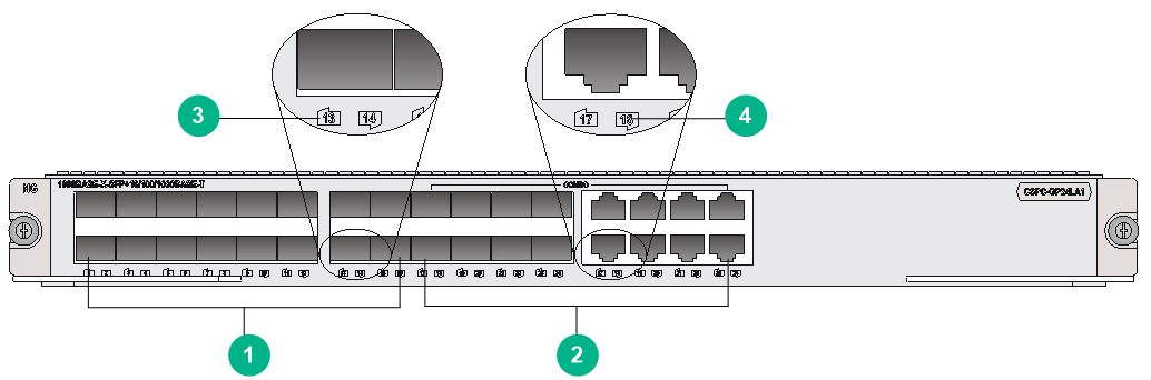
|
(1) 1000BASE-X-SFP fiber ports (16 in total) |
(2) Combo interfaces (8 in total) |
|
(3) SFP port LED. For the LED description, see Table2-139. |
(4) RJ-45 Ethernet port LED. For the LED description, see Table2-138. |
|
|
NOTE: · A combo interface is a logical interface that contains an SFP fiber port and an RJ-45 copper port. The two ports share one forwarding channel. As a result, they cannot work simultaneously. When you activate one port, the other port is automatically disabled. You can activate the fiber or copper port as needed. By default, the copper port is activated. · Use a category 5 or above twisted pair cable to connect a 1000BASE-T RJ-45 copper port. The maximum transmission distance is 100 m (328.08 ft). |
LEDs
Table2-138 RJ-45 Ethernet port LED description
|
LED |
Status |
Description |
|
RJ-45 Ethernet port LED |
Flashing |
The port is sending or receiving data. |
|
Steady on |
A link is present on the port. |
|
|
Off |
No link is present on the port. |
Table2-139 SFP port LED description
|
LED |
Status |
Description |
|
SFP port LED |
Flashing |
The port is sending or receiving data. |
|
Steady on |
A link is present on the port. |
|
|
Off |
No link is present on the port. |
Ports
Table2-140 Port specifications
|
Card model |
Description |
Connector type |
Port quantity |
Port transmission speed |
|
CSPC-GP24LA1 |
16-port 1000BASE-X Ethernet optical interface (SFP, LC) + 8-port combo interface module (A Type) |
RJ45 |
8 |
10/100/1000 Mbps |
|
LC |
24 |
100 Mbps |
||
|
155 Mbps |
||||
|
1000 Mbps |
Technical specifications
Table2-141 Technical specifications
|
Item |
Description |
|
Dimensions (H × W × D) |
40 × 399 × 352 mm (1.57 × 15.71 × 13.86 in) |
|
Weight |
3.01 kg (6.64 lb) |
|
Maximum power consumption |
75 W |
|
Power consumption (with typical configuration) |
68 W |
|
Minimum power consumption |
47 W |
|
Operating temperature |
0°C to 45°C (32°F to 113°F) |
CSPC-GP24XP2LB
View
Figure2-17 CSPC-GP24XP2LB view
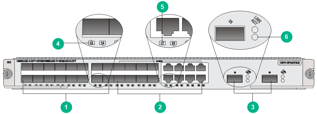
|
(1) 1000BASE-X-SFP fiber ports (16 in total) |
(2) Combo interfaces (8 in total) |
|
(3) 10GBASE-R-XFP fiber ports (2 in total) |
(4) SFP port LED. For the LED description, see Table2-143. |
|
(5) RJ-45 Ethernet port LED. For the LED description, see Table2-142. |
(6) XFP port LED. For the LED description, see Table2-144. |
LEDs
Table2-142 RJ-45 Ethernet port LED description
|
LED |
Status |
Description |
|
RJ-45 Ethernet port LED |
Flashing |
The port is sending or receiving data. |
|
Steady on |
A link is present on the port. |
|
|
Off |
No link is present on the port. |
Table2-143 SFP port LED description
|
LED |
Status |
Description |
|
SFP port LED |
Flashing |
The port is sending or receiving data. |
|
Steady on |
A link is present on the port. |
|
|
Off |
No link is present on the port. |
Table2-144 XFP port LED description
|
XFP port LED status |
Description |
|
|
LINK |
ACT |
|
|
Steady on |
Flashing green |
A link is present, and the XFP port is sending or receiving data. |
|
Steady on |
Off |
A link is present, but the XFP port is not sending or receiving data. |
|
Off |
Off |
No link is present on the XFP port. |
Ports
Table2-145 Port specifications
|
Card model |
Description |
Connector type |
Port quantity |
Port transmission speed |
|
CSPC-GP24XP2LB |
16-port 1000BASE-X optical interface (SFP, LC) + 8-port combo interface + 2-port 10GE optical interface module (XFP, LC) (B Type) |
RJ45 |
8 |
10/100/1000 Mbps |
|
LC |
24 |
155 Mbps |
||
|
1000 Mbps |
Technical specifications
Table2-146 Technical specifications
|
Item |
Description |
|
Dimensions (H × W × D) |
40 × 399 × 352 mm (1.57 × 15.71 × 13.86 in) |
|
Weight |
3.08 kg (6.79 lb) |
|
Maximum power consumption |
100 W |
|
Power consumption (with typical configuration) |
90 W |
|
Minimum power consumption |
51 W |
|
Operating temperature |
0°C to 45°C (32°F to 113°F) |
CSPC-GP44XP4LCX
View
Figure2-18 CSPC-GP44XP4LCX view
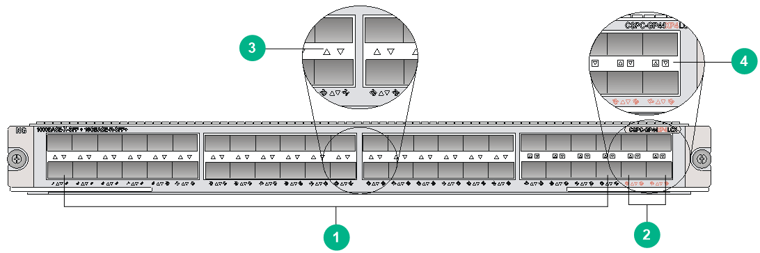
|
(1) 1000BASE-X-SFP fiber ports (44 in total) |
(2) 10GBASE-R-SFP+ fiber ports (4 in total) |
|
(3) SFP port LED. For the LED description, see Table2-147. |
(4) SFP+ port LED. For the LED description, see Table2-148. |
LEDs
Table2-147 SFP port LED description
|
LED |
Status |
Description |
|
SFP port LED |
Flashing |
The port is sending or receiving data. |
|
Steady on |
A link is present on the port. |
|
|
Off |
No link is present on the port. |
Table2-148 SFP+ port LED description
|
LED |
Status |
Description |
|
SFP+ port LED |
Flashing |
The port is sending or receiving data. |
|
Steady on |
A link is present on the port. |
|
|
Off |
No link is present on the port. |
|
|
NOTE: You can identify the speed of an SFP+ port by observing the color of its LED. Green indicates a speed of 10 Gbps, and yellow indicates a speed of 1000 Mbps. |
Ports
Table2-149 Port specifications
|
Card model |
Description |
Connector type |
Port quantity |
Port transmission speed |
|
CSPC-GP44XP4LCX |
44-port 1000BASE-X Ethernet optical interface module (SFP, LC) + 4-port 10GBASE Ethernet optical interface module (SFP+, LC) (C Type) |
LC |
44 |
100 Mbps |
|
155 Mbps |
||||
|
1000 Mbps |
||||
|
4 |
10 Gbps |
Technical specifications
Table2-150 Technical specifications
|
Item |
Description |
|
Dimensions (H × W × D) |
40 × 399 × 352 mm (1.57 × 15.71 × 13.86 in) |
|
Weight |
3.60 kg (7.94 lb) |
|
Maximum power consumption |
142 W |
|
Power consumption (with typical configuration) |
128 W |
|
Minimum power consumption |
118 W |
|
Operating temperature |
0°C to 45°C (32°F to 113°F) |
CSPC-GP48LB
View
Figure2-19 CSPC-GP48LB view
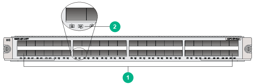
|
(1) 1000BASE-X-SFP fiber ports (48 in total) |
(2) SFP port LED. For the LED description, see Table2-151. |
LEDs
Table2-151 SFP port LED description
|
LED |
Status |
Description |
|
SFP port LED |
Flashing |
The port is sending or receiving data. |
|
Steady on |
A link is present on the port. |
|
|
Off |
No link is present on the port. |
Ports
Table2-152 Port specifications
|
Card model |
Description |
Connector type |
Port quantity |
Port transmission speed |
|
CSPC-GP48LB |
48-port enhanced 1000BASE-X Ethernet optical interface module (SFP, LC) (B Type) |
LC |
48 |
100 Mbps |
|
155 Mbps |
||||
|
1000 Mbps |
||||
|
2 |
10 Gbps |
Technical specifications
Table2-153 Technical specifications
|
Item |
Description |
|
Dimensions (H × W × D) |
40 × 399 × 352 mm (1.57 × 15.71 × 13.86 in) |
|
Weight |
3.25 kg (7.17 lb) |
|
Maximum power consumption |
110 W |
|
Power consumption (with typical configuration) |
99 W |
|
Minimum power consumption |
43 W |
|
Operating temperature |
0°C to 45°C (32°F to 113°F) |
CSPC-GT48LA1
View
Figure2-20 CSPC-GT48LA1 view
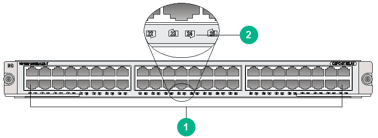
|
(1) 10/100/1000BASE-T copper ports (48 in total) |
(2) RJ-45 Ethernet port LED. For the LED description, see Table2-154. |
LEDs
Table2-154 RJ-45 Ethernet port LED description
|
LED |
Status |
Description |
|
RJ-45 Ethernet port LED |
Flashing |
The port is sending or receiving data. |
|
Steady on |
A link is present on the port. |
|
|
Off |
No link is present on the port. |
Ports
Table2-155 Port specifications
|
Card model |
Description |
Connector type |
Port quantity |
Port transmission speed |
|
CSPC-GT48LA1 |
48-port 10/100/1000BASE-T Ethernet interface module (RJ45) (A Type) |
RJ45 |
48 |
10/100/1000 Mbps |
Technical specifications
Table2-156 Technical specifications
|
Item |
Description |
|
Dimensions (H × W × D) |
40 × 399 × 352 mm (1.57 × 15.71 × 13.86 in) |
|
Weight |
3.31 kg (7.30 lb) |
|
Maximum power consumption |
95 W |
|
Power consumption (with typical configuration) |
86 W |
|
Minimum power consumption |
67 W |
|
Operating temperature |
0°C to 45°C (32°F to 113°F) |
CSPC-XLP6LCX
View
Figure2-21 CSPC-XLP6LCX view
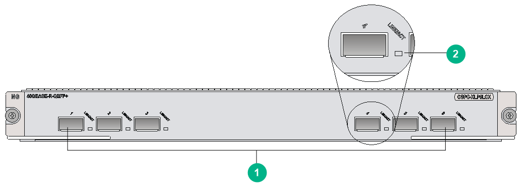
|
(1) 40GBASE-R-QSFP+ fiber ports (6 in total) |
(2) QSFP+ port LED. For the LED description, see Table2-157. |
LEDs
Table2-157 QSFP+ port LED description
|
LED |
Status |
Description |
|
QSFP+ port LED |
Flashing |
The QSFP+ port is sending or receiving data. |
|
Steady on |
A link is present on the QSFP+ port. |
|
|
Off |
No link is present on the QSFP+ port. |
Ports
Table2-158 Port specifications
|
Card model |
Description |
Connector type |
Port quantity |
Port transmission speed |
|
CSPC-XLP6LCX |
6-port 40GBASE Ethernet optical interface module (QSFP+, MPO) (C Type) |
LC/MPO |
6 |
40 Gbps |
Technical specifications
Table2-159 Technical specifications
|
Item |
Description |
|
Dimensions (H × W × D) |
40 × 399 × 352 mm (1.57 × 15.71 × 13.86 in) |
|
Weight |
3.95 kg (8.71 lb) |
|
Maximum power consumption |
290 W |
|
Power consumption (with typical configuration) |
261 W |
|
Minimum power consumption |
181 W |
|
Operating temperature |
0°C to 45°C (32°F to 113°F) |
CSPC-XP12LAX/CSPC-XP12LCX
View
Figure2-22 CSPC-XP12LCX view
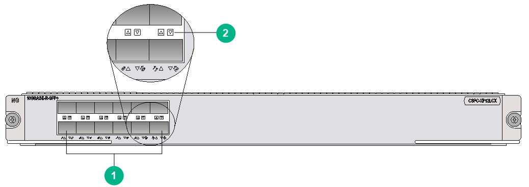
|
(1) 10GBASE-R-SFP+ fiber ports (12 in total) |
(2) SFP+ port LED. For the LED description, see Table2-160. |
The views of the CSPC-XP12LAX and CSPC-XP12LCX are similar. This figure uses the CSPC-XP12LCX as an example.
LEDs
Table2-160 SFP+ port LED description
|
LED |
Status |
Description |
|
SFP+ port LED |
Flashing |
The port is sending or receiving data. |
|
Steady on |
A link is present on the port. |
|
|
Off |
No link is present on the port. |
|
|
NOTE: You can identify the speed of an SFP+ port by observing the color of its LED. Green indicates a speed of 10 Gbps, and yellow indicates a speed of 1000 Mbps. |
Ports
Table2-161 Port specifications
|
Card model |
Description |
Connector type |
Port quantity |
Port transmission speed |
|
CSPC-XP12LAX |
12-port 10GE optical interface module |
LC |
12 |
10 Gbps |
|
CSPC-XP12LCX |
12-port 10GE optical interface module |
LC |
12 |
10 Gbps |
Technical specifications
Table2-162 Technical specifications
|
Item |
Description |
|
Dimensions (H × W × D) |
40 × 399 × 352 mm (1.57 × 15.71 × 13.86 in) |
|
Weight |
3.65 kg (8.05 lb) |
|
Maximum power consumption |
· CSPC-XP12LAX: 130 W · CSPC-XP12LCX: 173 W |
|
Power consumption (with typical configuration) |
· CSPC-XP12LAX: 117 W · CSPC-XP12LCX: 156 W |
|
Minimum power consumption |
· CSPC-XP12LAX: 107 W · CSPC-XP12LCX: 122 W |
|
Operating temperature |
0°C to 45°C (32°F to 113°F) |
CSPC-XP24LAX/CSPC-XP24LCX
View
Figure2-23 CSPC-XP24LCX view
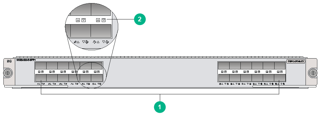
|
(1) 10GBASE-R-SFP+ fiber ports (24 in total) |
(2) SFP+ port LED. For the LED description, see Table2-163. |
The views of the CSPC-XP24LAX and CSPC-XP24LCX are similar. This figure uses the CSPC-XP24LCX as an example.
LEDs
Table2-163 SFP+ port LED description
|
LED |
Status |
Description |
|
SFP+ port LED |
Flashing |
The port is sending or receiving data. |
|
Steady on |
A link is present on the port. |
|
|
Off |
No link is present on the port. |
|
|
NOTE: You can identify the speed of an SFP+ port by observing the color of its LED. Green indicates a speed of 10 Gbps, and yellow indicates a speed of 1000 Mbps. |
Ports
Table2-164 Port specifications
|
Card model |
Description |
Connector type |
Port quantity |
Port transmission speed |
|
CSPC-XP24LAX |
24-port 10GBASE Ethernet optical interface module (SFP+, LC) (A Type) |
LC |
24 |
10 Gbps |
|
CSPC-XP24LCX |
4-port 10GBASE Ethernet optical interface module (SFP+, LC) (C Type) |
LC |
24 |
10 Gbps |
Technical specifications
Table2-165 Technical specifications
|
Item |
Description |
|
Dimensions (H × W × D) |
40 × 399 × 352 mm (1.57 × 15.71 × 13.86 in) |
|
Weight |
4.15 kg (9.15 lb) |
|
Maximum power consumption |
· CSPC-XP24LAX: 209 W · CSPC-XP24LCX: 294 W |
|
Power consumption (with typical configuration) |
· CSPC-XP24LAX: 189 W · CSPC-XP24LCX: 265 W |
|
Minimum power consumption |
· CSPC-XP24LAX: 153 W · CSPC-XP24LCX: 178 W |
|
Operating temperature |
0°C to 45°C (32°F to 113°F) |
CSPC-XP2LA1
View
Figure2-24 CSPC-XP2LA1 view
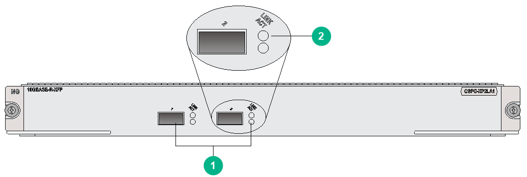
|
(1) 10GBASE-R-XFP fiber ports (2 in total) |
(2) XFP port LED. For the LED description, see Table2-166. |
LEDs
Table2-166 XFP port LED description
|
XFP port LED status |
Description |
|
|
LINK |
ACT |
|
|
Steady on |
Flashing green |
A link is present, and the XFP port is sending or receiving data. |
|
Steady on |
Off |
A link is present, but the XFP port is not sending or receiving data. |
|
Off |
Off |
No link is present on the XFP port. |
Ports
Table2-167 Port specifications
|
Card model |
Description |
Connector type |
Port quantity |
Port transmission speed |
|
CSPC-XP2LA1 |
2-port 10GBASE Ethernet optical interface module (XFP, LC) (A Type) |
LC |
2 |
10 Gbps |
Technical specifications
Table2-168 Technical specifications
|
Item |
Description |
|
Dimensions (H × W × D) |
40 × 399 × 352 mm (1.57 × 15.71 × 13.86 in) |
|
Weight |
2.93 kg (6.46 lb) |
|
Maximum power consumption |
55 W |
|
Power consumption (with typical configuration) |
50 W |
|
Minimum power consumption |
43 W |
|
Operating temperature |
0°C to 45°C (32°F to 113°F) |
CSPC-XP4LB
View
Figure2-25 CSPC-XP4LB view
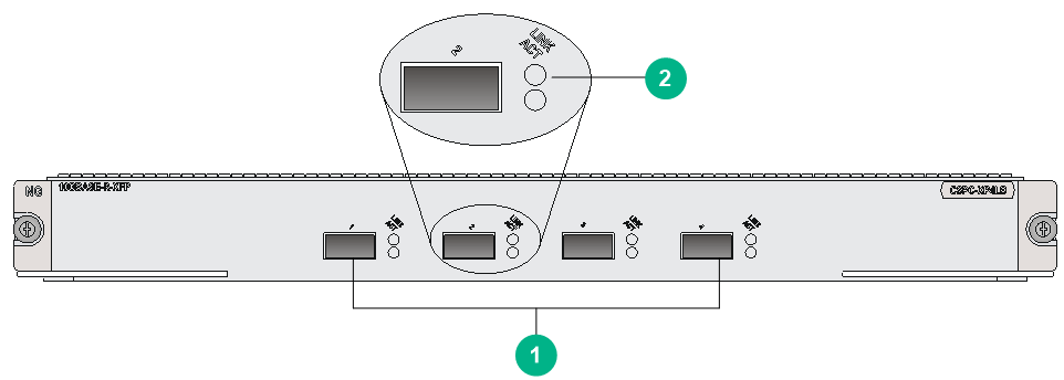
|
(1) 10GBASE-R-XFP fiber ports (2 in total) |
(2) XFP port LED. For the LED description, see Table2-169. |
LEDs
Table2-169 XFP port LED description
|
XFP port LED status |
Description |
|
|
LINK |
ACT |
|
|
Steady on |
Flashing green |
A link is present, and the XFP port is sending or receiving data. |
|
Steady on |
Off |
A link is present, but the XFP port is not sending or receiving data. |
|
Off |
Off |
No link is present on the XFP port. |
Ports
Table2-170 Port specifications
|
Card model |
Description |
Connector type |
Port quantity |
Port transmission speed |
|
CSPC-XP4LB |
4-port Enhanced 10GBASE Ethernet optical interface module (XFP, LC) (B Type) |
LC |
4 |
10 Gbps |
Technical specifications
Table2-171 Technical specifications
|
Item |
Description |
|
Dimensions (H × W × D) |
40 × 399 × 352 mm (1.57 × 15.71 × 13.86 in) |
|
Weight |
2.93 kg (6.46 lb) |
|
Maximum power consumption |
80 W |
|
Power consumption (with typical configuration) |
72 W |
|
Minimum power consumption |
53 W |
|
Operating temperature |
0°C to 45°C (32°F to 113°F) |
CSPC-XP8LB
View
Figure2-26 CSPC-XP8LB view
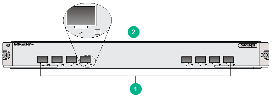
|
(1) 10GBASE-R-SFP+ fiber ports (8 in total) |
(2) SFP+ port LED. For the LED description, see Table2-172. |
LED
Table2-172 SFP+ port LED description
|
LED |
Status |
Description |
|
SFP+ port LED |
Flashing |
The port is sending or receiving data. |
|
Steady on |
A link is present on the port. |
|
|
Off |
No link is present on the port. |
|
|
NOTE: You can identify the speed of an SFP+ port by observing the color of its LED. Green indicates a speed of 10 Gbps, and yellow indicates a speed of 1000 Mbps. |
Ports
Table2-173 Port specifications
|
Card model |
Description |
Connector type |
Port quantity |
Port transmission speed |
|
CSPC-XP8LB |
8-port Enhanced 10GBASE Ethernet optical interface module (SFP+, LC) (B Type) |
LC |
8 |
10 Gbps |
Technical specifications
Table2-174 Technical specifications
|
Item |
Description |
|
Dimensions (H × W × D) |
40 × 399 × 352 mm (1.57 × 15.71 × 13.86 in) |
|
Weight |
3.44 kg (7.58 lb) |
|
Maximum power consumption |
170 W |
|
Power consumption (with typical configuration) |
153 W |
|
Minimum power consumption |
117 W |
|
Operating temperature |
0°C to 45°C (32°F to 113°F) |
Compatibility information
Table2-175 Compatibility matrix between CSPC cards and routers
|
Card model |
CR16006-F, CR16010-F, CR16014-F |
CR16010H-F (with five fabric modules), CR16018-F (with five fabric modules), CR16018-FA |
CR16010H-F (with four fabric modules), CR16018-F (with four fabric modules) |
CR16003E-F, CR16005E-F, CR16010E-F |
|
CSPC-GT48LA1 |
Supported |
Not supported |
Not supported |
Not supported |
|
CSPC-GE24L-E |
Supported |
Not supported |
Not supported |
Not supported |
|
CSPC-GP24LA1 |
Supported |
Not supported |
Not supported |
Not supported |
|
CSPC-GP24XP2LB |
Supported |
Not supported |
Not supported |
Not supported |
|
CSPC-GP24GE8XP2L-E |
Supported |
Not supported |
Not supported |
Not supported |
|
CSPC-GE16XP4L-E |
Supported |
Not supported |
Not supported |
Not supported |
|
CSPC-XP2LA1 |
Supported |
Not supported |
Not supported |
Not supported |
|
CSPC-XP4LB |
Supported |
Not supported |
Not supported |
Not supported |
|
CSPC-XP8LB |
Supported |
Not supported |
Not supported |
Not supported |
|
CSPC-GP48LB |
Supported |
Not supported |
Not supported |
Not supported |
|
CSPC-GP44XP4LCX |
Supported |
Not supported |
Not supported |
Not supported |
|
CSPC-XP24LCX |
Supported |
Not supported |
Not supported |
Not supported |
|
CSPC-XP24LAX |
Supported |
Not supported |
Not supported |
Not supported |
|
CSPC-XP12LCX |
Supported |
Not supported |
Not supported |
Not supported |
|
CSPC-XP12LAX |
Supported |
Not supported |
Not supported |
Not supported |
|
CSPC-XLP6LCX |
Supported |
Not supported |
Not supported |
Not supported |
|
CSPC-CP1LCX |
Supported |
Not supported |
Not supported |
Not supported |
|
CSPC-CP2LB |
Supported |
Not supported |
Not supported |
Not supported |
CEPC LPUs (interface modules)
CEPC-CP4RX/CEPC-CP4RXA
View
Figure2-27 CEPC-CP4RX view
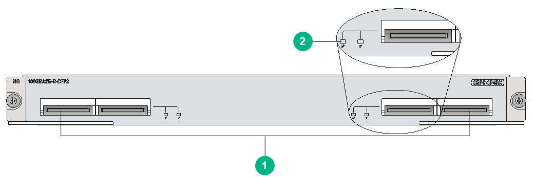
|
(1) 100GBASE-R-CFP2 fiber ports (4 in total) |
(2) CFP2 port LED. For the LED description, see Table2-176. |
The views of CEPC-CP4RX and CEPC-CP4RXA are similar. This figure uses the CEPC-CP4RX as an example.
LEDs
Table2-176 CFP2 port LED description
|
LED |
Status |
Description |
|
CFP2 port LED |
Flashing |
The CFP2 port is sending or receiving data at 100 Gbps. |
|
Steady on |
A 100 Gbps link is present on the CFP2 port. |
|
|
Off |
No link is present on the CFP2 port. |
Ports
Table2-177 Port specifications
|
Card model |
Description |
Connector type |
Port quantity |
Port transmission speed |
|
CEPC-CP4RX |
4-port 100GBASE Ethernet optical interface module (CFP2) |
LC |
4 |
100 Gbps |
|
CEPC-CP4RXA |
4-port 100GBASE Ethernet optical interface module A (CFP2) |
LC |
4 |
100 Gbps |
Technical specifications
Table2-178 Technical specifications
|
Item |
Description |
|
Dimensions (H × W × D) |
40 × 399 × 352 mm (1.57 × 15.71 × 13.86 in) |
|
Weight |
4.20 kg (9.26 lb) |
|
Maximum power consumption |
368 W |
|
Power consumption (with typical configuration) |
331 W |
|
Minimum power consumption |
228.5 W |
|
Operating temperature |
0°C to 45°C (32°F to 113°F) |
CEPC-CP4RX-L
View
Figure2-28 CEPC-CP4RX-L view
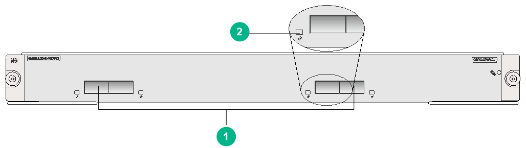
|
(1) 100GBASE-QSFP28 fiber ports (4 in total) (100G QSFP 28 modules supported) |
(2) QSFP 28 port LED. For the LED description, see Table2-179. |
LEDs
Table2-179 QSFP28 port LED description
|
LED |
Status |
Description |
|
QSFP28 port LED |
Flashing |
The QSFP28 port is sending or receiving data at 100 Gbps. |
|
Steady on |
A 100 Gbps link is present on the QSFP28 port. |
|
|
Off |
No link is present on the QSFP28 port. |
Ports
Table2-180 Port specifications
|
Card model |
Description |
Connector type |
Port quantity |
Port transmission speed |
|
CEPC-CP4RX-L |
4-port 100G Ethernet optical interface line processing unit (QSFP28, LC) |
LC |
4 |
100 Gbps |
|
40 Gbps |
Technical specifications
Table2-181 Technical specifications
|
Item |
Description |
|
Dimensions (H × W × D) |
40 × 399 × 352 mm (1.57 × 15.71 × 13.86 in) |
|
Weight |
8.30 kg (18.30 lb) |
|
Maximum power consumption |
354 W |
|
Power consumption (with typical configuration) |
252 W |
|
Minimum power consumption |
191 W |
|
Operating temperature |
0°C to 45°C (32°F to 113°F) |
CEPC-CQ16L1
View
Figure2-29 CEPC-CQ16L1 view
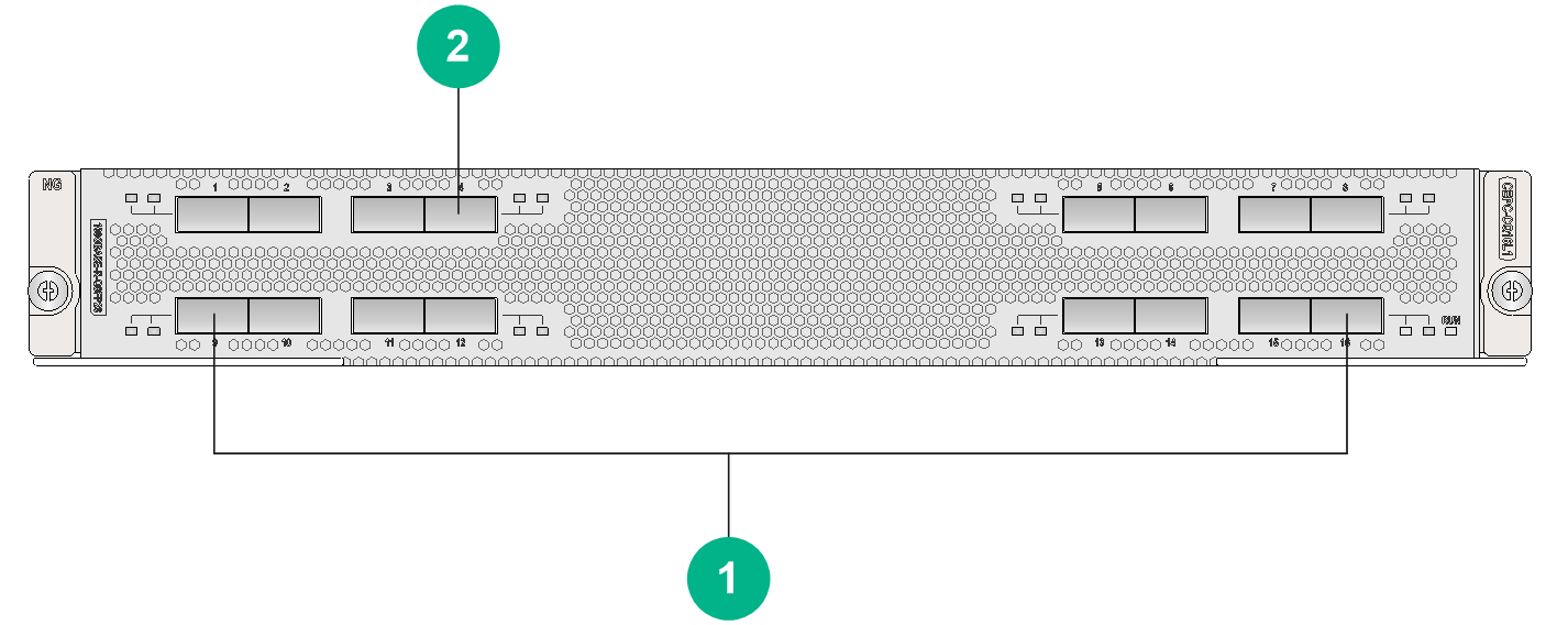
|
(1) 100GBASE-QSFP28 fiber ports (16 in total) |
(2) QSFP 28 port LED. For the LED description, see Table2-182. |
LEDs
Table2-182 QSFP28 port LED description
|
LED |
Status |
Description |
|
QSFP28 port LED |
Flashing |
The QSFP28 port is sending or receiving data at 100 Gbps. |
|
Steady on |
A 100 Gbps link is present on the QSFP28 port. |
|
|
Off |
No link is present on the QSFP28 port. |
Ports
|
|
IMPORTANT: Only ports 1, 2, 7, 8, 9, 10, 15, and 16 support switching the speed between 100 Gbps and 40 Gbps. |
Table2-183 Port specifications
|
Card model |
Description |
Connector type |
Port quantity |
Port transmission speed |
|
CEPC-CQ16L1 |
16-port 100G Ethernet optical interface line processing unit (QSFP28,LC) |
LC |
16 |
100 Gbps |
|
40 Gbps |
Technical specifications
Table2-184 Technical specifications
|
Item |
Description |
|
Dimensions (H × W × D) |
52.5 × 399 × 370 mm (2.07 × 15.71 × 14.57 in) |
|
Weight |
8.25 kg (18.19 lb) |
|
Maximum power consumption |
1240 W |
|
Power consumption (with typical configuration) |
970 W |
|
Minimum power consumption |
760 W |
|
Operating temperature |
0°C to 45°C (32°F to 113°F) |
CEPC-CQ8L/CEPC-CQ8LA/CEPC-CQ8L1A/CEPC-CQ8L3A
View
Figure2-30 CEPC-CQ8L view
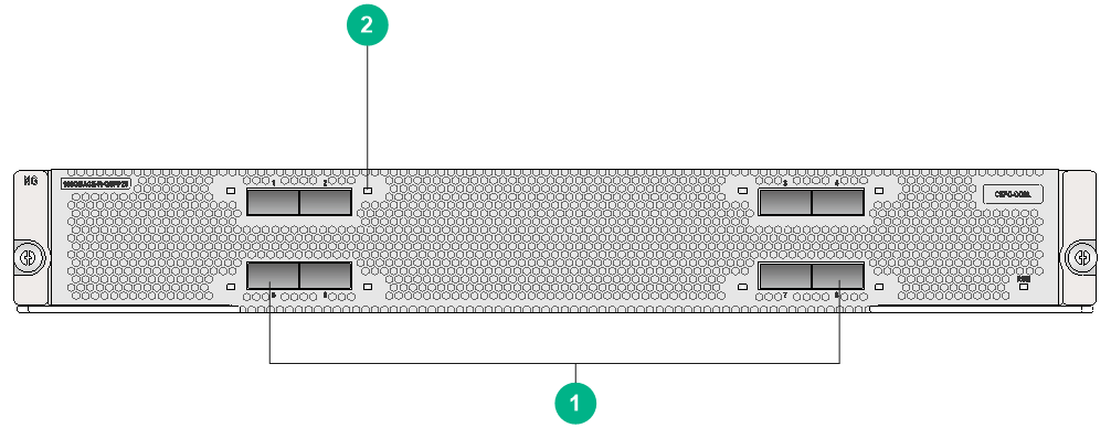
|
(1) 100GBASE-QSFP28 fiber ports (8 in total) |
(2) QSFP 28 port LED. For the LED description, see Table2-185. |
The views of CEPC-CQ8L, CEPC-CQ8LA, CEPC-CQ8L1A, and CEPC-CQ8L3A are similar. This figure uses the CEPC-CQ8L as an example.
LEDs
Table2-185 QSFP28 port LED description
|
LED |
Status |
Description |
|
QSFP28 port LED |
Flashing |
The QSFP28 port is sending or receiving data at 100 Gbps. |
|
Steady on |
A 100 Gbps link is present on the QSFP28 port. |
|
|
Off |
No link is present on the QSFP28 port. |
Ports
Table2-186 Port specifications
|
Card model |
Description |
Connector type |
Port quantity |
Port transmission speed |
|
CEPC-CQ8L |
8-port 100G Ethernet optical interface line processing unit (QSFP28, LC) |
LC |
8 |
100 Gbps |
|
CEPC-CQ8LA |
8-port 100G Ethernet optical interface line processing unit A (QSFP28,LC) |
LC |
8 |
100 Gbps |
|
40 Gbps |
||||
|
CEPC-CQ8L1A |
8-port 100G Ethernet optical interface line processing unit A (QSFP28,LC) |
LC |
8 |
100 Gbps |
|
40 Gbps |
||||
|
CEPC-CQ8L3A |
8-port 100G Ethernet optical interface line processing unit A (QSFP28,LC) |
LC |
8 |
100 Gbps |
|
40 Gbps |
Technical specifications
Table2-187 Technical specifications
|
Item |
Description |
|
Dimensions (H × W × D) |
52.5 × 399 × 370 mm (2.07 × 15.71 × 14.57 in) |
|
Weight |
8.00 kg (17.64 lb) |
|
Maximum power consumption |
· CEPC-CQ8L, CEPC-CQ8L1A, CEPC-CQ8L3A: 1100 W · CEPC-CQ8LA: 810 W |
|
Power consumption (with typical configuration) |
· CEPC-CQ8L, CEPC-CQ8L1A, CEPC-CQ8L3A: 880 W · CEPC-CQ8LA: 705 W |
|
Minimum power consumption |
· CEPC-CQ8L, CEPC-CQ8L1A, CEPC-CQ8L3A: 653 W · CEPC-CQ8LA: 610 W |
|
Operating temperature |
0°C to 45°C (32°F to 113°F) |
CEPC-DQ2L1-G
View
Figure2-31 CEPC-DQ2L1-G view
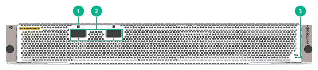
|
(1) QSFP-DD port LED. For the LED description, see Table2-188. |
(2) 400GBASE-R-QSFP-DD fiber ports (2 in total) (400G QSFP-DD modules supported) |
|
(3) Card status LED. For the LED description, see Table2-189. |
|
LEDs
Table2-188 QSFP-DD port LED description
|
LED |
Status |
Description |
|
QSFP-DD port LED |
Flashing |
The QSFP-DD port is sending or receiving data. |
|
On |
A link is present on the QSFP-DD port. |
|
|
Off |
No link is present on the QSFP-DD port. |
Table2-189 Card status LED description
|
LED |
Status |
Description |
|
RUN (Green) |
Steady on |
The card is faulty. |
|
Off |
The card is faulty or is not in position. |
|
|
Flashing (about once per second) |
The card is operating correctly. |
|
|
Fast flashing (about eight times per second) |
The card is starting up. If the LED keeps fast flashing, card registration has failed. |
Ports
Table2-190 Port specifications
|
Card model |
Description |
Connector type |
Port quantity |
Port transmission speed |
|
CEPC-DQ2L1-G |
2-port 400G Ethernet optical interface line processing unit (QSFP-DD,LC) |
LC |
2 |
400 Gbps |
Technical specifications
Table2-191 Technical specifications
|
Item |
Description |
|
Dimensions (H × W × D) |
52.5 × 399 × 370 mm (2.07 × 15.71 × 14.57 in) |
|
Weight |
6.96 kg (15.34 lb) |
|
Maximum power consumption |
540 W |
|
Power consumption (with typical configuration) |
510 W |
|
Minimum power consumption |
450 W |
|
Operating temperature |
0°C to 45°C (32°F to 113°F) |
CEPC-XP24LX
View
Figure2-32 CEPC-XP24LX view
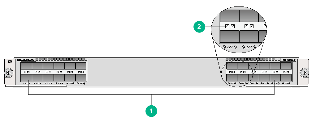
|
(1) 10GBASE-R/W-SFP+ fiber ports (24 in total) (10GE SFP+ modules supported) |
(2) SFP+ port LED. For the LED description, see Table2-192. |
LEDs
Table2-192 SFP+ port LED description
|
LED |
Status |
Description |
|
SFP+ port LED |
Flashing |
The SFP+ port is sending or receiving data. |
|
Steady on |
A link is present on the SFP+ port. |
|
|
Off |
No link is present on the SFP+ port. |
Ports
Table2-193 Port specifications
|
Card model |
Description |
Connector type |
Port quantity |
Port transmission speed |
|
CEPC-XP24LX |
24-port 10GBASE-R/W Ethernet optical interface line processing unit (SFP+, LC) |
LC |
24 |
10 Gbps |
Technical specifications
Table2-194 Technical specifications
|
Item |
Description |
|
Dimensions (H × W × D) |
40 × 399 × 352 mm (1.57 × 15.71 × 13.86 in) |
|
Weight |
4.70 kg (10.36 lb) |
|
Maximum power consumption |
321 W |
|
Power consumption (with typical configuration) |
289 W |
|
Minimum power consumption |
237.6 W |
|
Operating temperature |
0°C to 45°C (32°F to 113°F) |
CEPC-XP48RX
View
Figure2-33 CEPC-XP48RX view
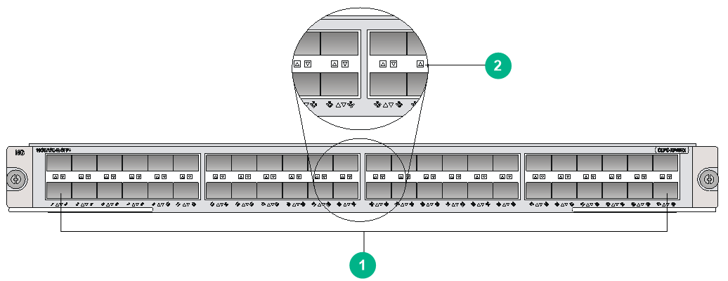
|
(1) 10GBASE-R-SFP+ fiber ports (48 in total) |
(2) SFP+ port LED. For the LED description, see Table2-195. |
LEDs
Table2-195 SFP+ port LED description
|
LED |
Status |
Description |
|
SFP+ port LED |
Flashing |
The SFP+ port is sending or receiving data. |
|
Steady on |
A link is present on the SFP+ port. |
|
|
Off |
No link is present on the SFP+ port. |
Ports
Table2-196 Port specifications
|
Card model |
Description |
Connector type |
Port quantity |
Port transmission speed |
|
CEPC-XP48RX |
48-port 10GBASE-R/W Ethernet optical interface module (SFP+, LC) |
LC |
48 |
10 Gbps |
Technical specifications
Table2-197 Technical specifications
|
Item |
Description |
|
Dimensions (H × W × D) |
40 × 399 × 352 mm (1.57 × 15.71 × 13.86 in) |
|
Weight |
4.75 kg (10.47 lb) |
|
Maximum power consumption |
407 W |
|
Power consumption (with typical configuration) |
336 W |
|
Minimum power consumption |
234.8 W |
|
Operating temperature |
0°C to 45°C (32°F to 113°F) |
CEPC-XP4LX
View
Figure2-34 CEPC-XP4LX view
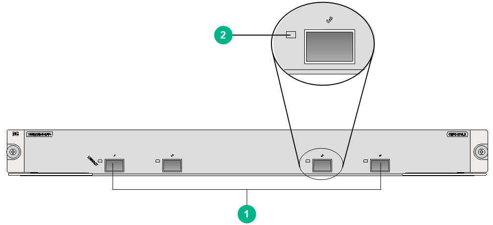
|
(1) 10GBASE-R/W-SFP+ fiber ports (4 in total) (10GE SFP+ modules supported) |
(2) SFP+ port LED. For the LED description, see Table2-198. |
LEDs
Table2-198 SFP+ port LED description
|
LED |
Status |
Description |
|
SFP+ port LED |
Flashing |
The SFP+ port is sending or receiving data. |
|
Steady on |
A link is present on the SFP+ port. |
|
|
Off |
No link is present on the SFP+ port. |
Ports
Table2-199 Port specifications
|
Card model |
Description |
Connector type |
Port quantity |
Port transmission speed |
|
CEPC-XP4LX |
4-port 10GBASE-R/W Ethernet optical interface line processing unit module (SFP+, LC) |
LC |
4 |
10 Gbps |
Technical specifications
Table2-200 Technical specifications
|
Item |
Description |
|
Dimensions (H × W × D) |
40 × 399 × 352 mm (1.57 × 15.71 × 13.86 in) |
|
Weight |
4.90 kg (10.80 lb) |
|
Maximum power consumption |
184 W |
|
Power consumption (with typical configuration) |
117 W |
|
Minimum power consumption |
102 W |
|
Operating temperature |
0°C to 45°C (32°F to 113°F) |
Configuration restrictions and guidelines
For adequate ventilation and cooling, you can install the CEPC-CP4RX, CEPC-XP48RX, and CEPC-XP24LX cards in the following slots only when the other slots are not available.
· CR16010-F router—Slots 0, 8 and 9.
· CR16014-F router—Slots 0 and 13.
Compatibility information
Table2-201 Compatibility matrix between CEPC cards and routers (1)
|
Card model |
CR16006-F |
CR16010-F, CR16014-F |
CR16010H-F (with five fabric modules), CR16018-F (with five fabric modules) |
CR16010H-F (with four fabric modules), CR16018-F (with four fabric modules) |
CR16010H-FA, CR16018-FA |
|
CEPC-XP48RX |
Not supported |
Supported |
Supported |
Not supported |
Not supported |
|
CEPC-CP4RX |
Not supported |
Supported |
Supported |
Not supported |
Not supported |
|
CEPC-CP4RXA |
Not supported |
Not supported |
Not supported |
Not supported |
Supported |
|
CEPC-CP4RX-L |
Not supported |
Supported |
Supported |
Not supported |
Not supported |
|
CEPC-XP24LX |
Not supported |
Supported |
Supported |
Not supported |
Not supported |
|
CEPC-XP4LX |
Supported |
Supported |
Supported |
Not supported |
Not supported |
|
CEPC-CQ8L |
Not supported |
Not supported |
Supported |
Supported |
Not supported |
|
CEPC-CQ8LA |
Not supported |
Not supported |
Not supported |
Not supported |
Supported |
|
CEPC-CQ8L1A |
Not supported |
Not supported |
Not supported |
Not supported |
Supported |
|
CEPC-CQ8L3A |
Not supported |
Not supported |
Not supported |
Not supported |
Supported |
|
CEPC-CQ16L1 |
Not supported |
Not supported |
Supported |
Supported |
Not supported |
|
CEPC-DQ2L1-G |
Not supported |
Not supported |
Supported |
Not supported |
Not supported |
Table2-202 Compatibility matrix between CEPC cards and routers (2)
|
Card model |
CR16003E-F |
CR16005E-F |
CR16010E-F |
|
CEPC-XP48RX |
Not supported |
Not supported |
Not supported |
|
CEPC-CP4RX |
Not supported |
Not supported |
Not supported |
|
CEPC-CP4RXA |
Not supported |
Not supported |
Not supported |
|
CEPC-CP4RX-L |
Not supported |
Not supported |
Not supported |
|
CEPC-XP24LX |
Not supported |
Not supported |
Not supported |
|
CEPC-XP4LX |
Not supported |
Supported |
Supported |
|
CEPC-CQ8L |
Not supported |
Not supported |
Not supported |
|
CEPC-CQ8LA |
Supported |
Not supported |
Supported |
|
CEPC-CQ8L1A |
Not supported |
Not supported |
Not supported |
|
CEPC-CQ8L3A |
Not supported |
Not supported |
Not supported |
|
CEPC-CQ16L1 |
Supported |
Not supported |
Supported |
|
CEPC-DQ2L1-G |
Supported |
Not supported |
Supported |
CSPEX base cards
CSPEX-1104-E/CSPEX-1204/CSPEX-1304X/CSPEX-1404X/CSPEX-1504X/CSPEX-1504XA
|
|
IMPORTANT: A CSPEX-1104-E card supports a maximum of three MIC-XP4L1 and MIC-GP4L subcards in total. |
View
Figure2-35 CSPEX-1204 view
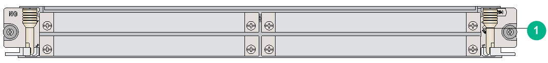
|
(1) Card status LED. For the LED description, see Table2-203. |
The views of CSPEX-1204, CSPEX-1304X, CSPEX-1404X, CSPEX-1504X, CSPEX-1504XA, and CSPEX-1104-E are similar. This figure uses the CSPEX-1204 as an example.
LEDs
|
LED |
Status |
Description |
|
RUN (Green) |
Steady on |
The card is faulty. |
|
Off |
The card is faulty or is not in position. |
|
|
Flashing (about once per second) |
The card is operating correctly. |
|
|
Fast flashing (about eight times per second) |
The card is starting up. If the LED keeps fast flashing, card registration has failed. |
Subcard slots
Table2-204 Subcard slots
|
Card model |
Number of subcard slots |
|
CSPEX-1104-E |
4 |
|
CSPEX-1204 |
4 |
|
CSPEX-1304X |
4 |
|
CSPEX-1404X |
4 |
|
CSPEX-1504X |
4 |
|
CSPEX-1504XA |
4 |
Technical specifications
Table2-205 Technical specifications
|
Item |
Description |
|
Dimensions (H × W × D) |
40 × 399 × 352 mm (1.57 × 15.71 × 13.86 in) |
|
Weight |
· CSPEX-1104-E: 3.45 kg (7.61 lb) · CSPEX-1204: 3.50 kg (7.72 lb) · CSPEX-1304X: 3.75 kg (8.27 lb) · CSPEX-1404X: 7.20 kg (15.87 lb) · CSPEX-1504X: 7.20 kg (15.87 lb) · CSPEX-1504XA: 3.80 kg (8.38 lb) |
|
Maximum power consumption |
· CSPEX-1104-E: 164 W · CSPEX-1204: 190 W · CSPEX-1304X: 184 W · CSPEX-1404X: 230 W · CSPEX-1504X, CSPEX-1504XA: 261 W |
|
Power consumption (with typical configuration) |
· CSPEX-1104-E: 88 W · CSPEX-1204: 104 W · CSPEX-1304X: 101 W · CSPEX-1404X: 138 W · CSPEX-1504X, CSPEX-1504XA: 154 W |
|
Minimum power consumption |
· CSPEX-1104-E: 79 W · CSPEX-1204: 88 W · CSPEX-1304X: 90 W · CSPEX-1404X: 111.6 W · CSPEX-1504X, CSPEX-1504XA: 112.1 W |
|
Operating temperature |
0°C to 45°C (32°F to 113°F) |
CSPEX-1502X/CSPEX-1502XA/CSPEX-1602X/CSPEX-1602XA
View
Figure2-36 CSPEX-1602X view
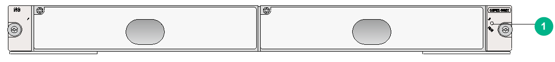
|
(1) Card status LED. For the LED description, see Table2-206. |
The views of the CSPEX-1602X, CSPEX-1602XA, CSPEX-1502X, and CSPEX-1502XA are similar. This figure uses the CSPEX-1602X as an example.
LEDs
|
LED |
Status |
Description |
|
RUN (Green) |
Steady on |
The card is faulty. |
|
Off |
The card is faulty or is not in position. |
|
|
Flashing (about once per second) |
The card is operating correctly. |
|
|
Fast flashing (about eight times per second) |
The card is starting up. If the LED keeps fast flashing, card registration has failed. |
Subcard slots
Table2-207 Subcard slots
|
Card model |
Number of subcard slots |
|
CSPEX-1502X |
2 |
|
CSPEX-1502XA |
2 |
|
CSPEX-1602X |
2 |
|
CSPEX-1602XA |
2 |
Technical specifications
Table2-208 Technical specifications
|
Item |
Description |
|
Dimensions (H × W × D) |
· CSPEX-1502X, CSPEX-1602X, CSPEX-1602XA: 40 × 399 × 352 mm (1.57 × 15.71 × 13.86 in) · CSPEX-1502XA: 52.5 × 399 × 361 mm (2.07 × 15.71 × 14.21 in) |
|
Weight |
· CSPEX-1502X: 3.95 kg (8.71 lb) · CSPEX-1502XA: 5.00 kg (11.02 lb) · CSPEX-1602X, CSPEX-1602XA: 7.50 kg (16.53 lb) |
|
Maximum power consumption |
· CSPEX-1502X, CSPEX-1502XA: 270 W · CSPEX-1602X, CSPEX-1602XA: 354 W |
|
Power consumption (with typical configuration) |
· CSPEX-1502X, CSPEX-1502XA: 135 W · CSPEX-1602X, CSPEX-1602XA: 222 W |
|
Minimum power consumption |
· CSPEX-1502X, CSPEX-1502XA: 120 W · CSPEX-1602X, CSPEX-1602XA: 174.6 W |
|
Operating temperature |
0°C to 45°C (32°F to 113°F) |
CSPEX-1512X/CSPEX-1612X/CSPEX-1812X/CSPEX-1812X-E/CSPEX-1802X/CSPEX-1802XA
View
Figure2-37 CSPEX-1512X view
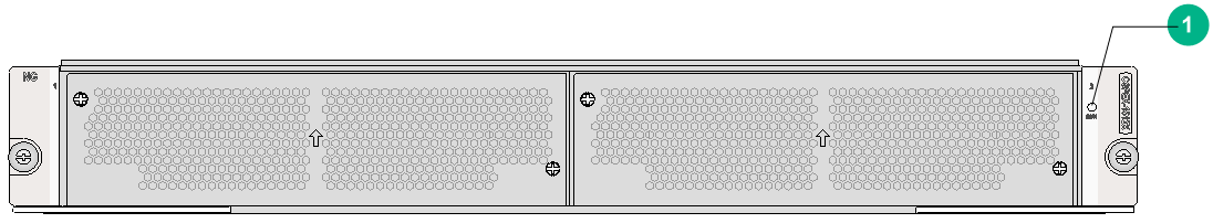
|
(1) Card status LED. For the LED description, see Table2-209. |
The views of the CSPEX-1512X, CSPEX-1612X, CSPEX-1812X, CSPEX-1812X-E, CSPEX-1802X, and CSPEX-1802XA are similar. This figure uses the CSPEX-1512X as an example.
LEDs
|
LED |
Status |
Description |
|
RUN (Green) |
Steady on |
The card is faulty. |
|
Off |
The card is faulty or is not in position. |
|
|
Flashing (about once per second) |
The card is operating correctly. |
|
|
Fast flashing (about eight times per second) |
The card is starting up. If the LED keeps fast flashing, card registration has failed. |
Subcard slots
Table2-210 Subcard slots
|
Card model |
Number of subcard slots |
|
CSPEX-1512X |
2 |
|
CSPEX-1612X |
2 |
|
CSPEX-1812X |
2 |
|
CSPEX-1812X-E |
2 |
|
CSPEX-1802X |
2 |
|
CSPEX-1802XA |
2 |
Technical specifications
Table2-211 Technical specifications
|
Item |
Description |
|
Dimensions (H × W × D) |
52.5 × 399 × 352 mm (2.07 × 15.71 × 13.86 in) |
|
Weight |
· CSPEX-1512X: 5.40 kg (11.90 lb) · CSPEX-1612X: 8.75 kg (19.29 lb) · CSPEX-1812X: 5.95 kg (13.12 lb) · CSPEX-1812X-E, CSPEX-1802X, CSPEX-1802XA: 9.00 kg (19.84 lb) |
|
Maximum power consumption |
· CSPEX-1512X: 281 W · CSPEX-1612X: 320 W · CSPEX-1812X: 657 W · CSPEX-1812X-E, CSPEX-1802X, CSPEX-1802XA: 486 W |
|
Power consumption (with typical configuration) |
· CSPEX-1512X: 202 W · CSPEX-1612X: 238 W · CSPEX-1812X: 426 W · CSPEX-1812X-E, CSPEX-1802X, CSPEX-1802XA: 333 W |
|
Minimum power consumption |
· CSPEX-1512X: 185 W · CSPEX-1612X: 200 W · CSPEX-1812X: 413 W · CSPEX-1812X-E. CSPEX-1802X, CSPEX-1802XA: 275 W |
|
Operating temperature |
0°C to 45°C (32°F to 113°F) |
CSPEX-1804X
View
Figure2-38 CSPEX-1804X view
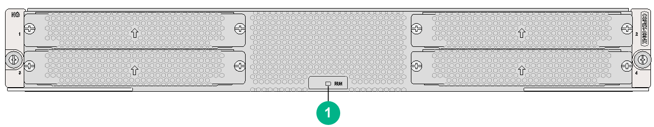
|
(1) Card status LED. For the LED description, see Table2-212. |
LEDs
|
LED |
Status |
Description |
|
RUN (Green) |
Steady on |
The card is faulty. |
|
Off |
The card is faulty or is not in position. |
|
|
Flashing (about once per second) |
The card is operating correctly. |
|
|
Fast flashing (about eight times per second) |
The card is starting up. If the LED keeps fast flashing, card registration has failed. |
Subcard slots
Table2-213 Subcard slots
|
Card model |
Number of subcard slots |
|
CSPEX-1804X |
4 |
Technical specifications
Table2-214 Technical specifications
|
Item |
Description |
|
Dimensions (H × W × D) |
52.5 × 399 × 352 mm (2.07 × 15.71 × 13.86 in) |
|
Weight |
6.30 kg (13.89 lb) |
|
Maximum power consumption |
625 W |
|
Power consumption (with typical configuration) |
510 W |
|
Minimum power consumption |
460 W |
|
Operating temperature |
0°C to 45°C (32°F to 113°F) |
CSPEX-2304X-G
View
Figure2-39 CSPEX-2304X-G view
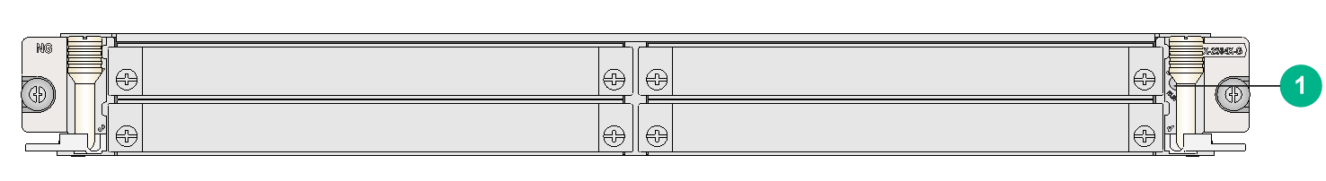
|
(1) Card status LED. For the LED description, see Table2-215. |
LEDs
|
LED |
Status |
Description |
|
RUN (Green) |
Steady on |
The card is faulty. |
|
Off |
The card is faulty or is not in position. |
|
|
Flashing (about once per second) |
The card is operating correctly. |
|
|
Fast flashing (about eight times per second) |
The card is starting up. If the LED keeps fast flashing, card registration has failed. |
Subcard slots
Table2-216 Subcard slots
|
Card model |
Number of subcard slots |
|
CSPEX-2304X-G |
4 |
Technical specifications
Table2-217 Technical specifications
|
Item |
Description |
|
Dimensions (H × W × D) |
40 × 399 × 352 mm (1.57 × 15.71 × 13.86 in) |
|
Weight |
4.65 kg (10.25 lb) |
|
Maximum power consumption |
280 W |
|
Power consumption (with typical configuration) |
242 W |
|
Minimum power consumption |
200 W |
|
Operating temperature |
0°C to 45°C (32°F to 113°F) |
CSPEX-2304X-LG
View
Figure2-40 CSPEX-2304X-LG view
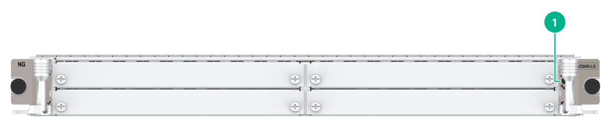
|
(1) Card status LED. For the LED description, see Table2-218. |
LEDs
|
LED |
Status |
Description |
|
RUN (Green) |
Steady on |
The card is faulty. |
|
Off |
The card is faulty or is not in position. |
|
|
Flashing (about once per second) |
The card is operating correctly. |
|
|
Fast flashing (about eight times per second) |
The card is starting up. If the LED keeps fast flashing, card registration has failed. |
Subcard slots
Table2-219 Subcard slots
|
Card model |
Number of subcard slots |
|
CSPEX-2304X-LG |
4 |
Technical specifications
Table2-220 Technical specifications
|
Item |
Description |
|
Dimensions (H × W × D) |
40 × 399 × 352 mm (1.57 × 15.71 × 13.86 in) |
|
Weight |
4.65 kg (10.25 lb) |
|
Maximum power consumption |
280 W |
|
Power consumption (with typical configuration) |
242 W |
|
Minimum power consumption |
200 W |
|
Operating temperature |
0°C to 45°C (32°F to 113°F) |
CSPEX-2314X-G
View
Figure2-41 CSPEX-2314X-G view
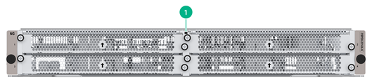
|
(1) Card status LED. For the LED description, see Table2-221. |
LEDs
|
LED |
Status |
Description |
|
RUN (Green) |
Steady on |
The card is faulty. |
|
Off |
The card is faulty or is not in position. |
|
|
Flashing (about once per second) |
The card is operating correctly. |
|
|
Fast flashing (about eight times per second) |
The card is starting up. If the LED keeps fast flashing, card registration has failed. |
Subcard slots
Table2-222 Subcard slots
|
Card model |
Number of subcard slots |
|
CSPEX-2314X-G |
4 |
Technical specifications
Table2-223 Technical specifications
|
Item |
Description |
|
Dimensions (H × W × D) |
52.5 × 399 × 352 mm (2.07 × 15.71 × 13.86 in) |
|
Weight |
11.57 kg (25.51 lb) |
|
Maximum power consumption |
385 W |
|
Power consumption (with typical configuration) |
333 W |
|
Minimum power consumption |
185 W |
|
Operating temperature |
0°C to 45°C (32°F to 113°F) |
CSPEX-2314X-G1
View
Figure2-42 CSPEX-2314X-G1 view
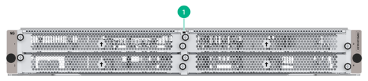
|
(1) Card status LED. For the LED description, see Table2-224. |
LEDs
|
LED |
Status |
Description |
|
RUN (Green) |
Steady on |
The card is faulty. |
|
Off |
The card is faulty or is not in position. |
|
|
Flashing (about once per second) |
The card is operating correctly. |
|
|
Fast flashing (about eight times per second) |
The card is starting up. If the LED keeps fast flashing, card registration has failed. |
Subcard slots
Table2-225 Subcard slots
|
Card model |
Number of subcard slots |
|
CSPEX-2314X-G1 |
4 |
Technical specifications
Table2-226 Technical specifications
|
Item |
Description |
|
Dimensions (H × W × D) |
52.5 × 399 × 352 mm (2.07 × 15.71 × 13.86 in) |
|
Weight |
5.15 kg (11.35 lb) |
|
Maximum power consumption |
320 W |
|
Power consumption (with typical configuration) |
268 W |
|
Minimum power consumption |
120 W |
|
Operating temperature |
0°C to 45°C (32°F to 113°F) |
CSPEX-2314X-G2
View
Figure2-43 CSPEX-2314X-G2 view
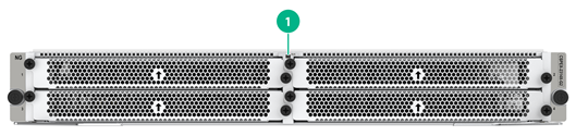
|
(1) Card status LED. For the LED description, see Table2-227. |
LEDs
|
LED |
Status |
Description |
|
RUN (Green) |
Steady on |
The card is faulty. |
|
Off |
The card is faulty or is not in position. |
|
|
Flashing (about once per second) |
The card is operating correctly. |
|
|
Fast flashing (about eight times per second) |
The card is starting up. If the LED keeps fast flashing, card registration has failed. |
Subcard slots
Table2-228 Subcard slots
|
Card model |
Number of subcard slots |
|
CSPEX-2314X-G2 |
4 |
Technical specifications
Table2-229 Technical specifications
|
Item |
Description |
|
Dimensions (H × W × D) |
52.5 × 399 × 352 mm (2.07 × 15.71 × 13.86 in) |
|
Weight |
5.15 kg (11.35 lb) |
|
Maximum power consumption |
320 W |
|
Power consumption (with typical configuration) |
268 W |
|
Minimum power consumption |
120 W |
|
Operating temperature |
0°C to 45°C (32°F to 113°F) |
CSPEX-2612XA/CSPEX-2612X3A
View
Figure2-44 CSPEX-2612X3A view
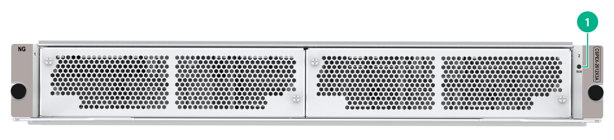
|
(1) Card status LED. For the LED description, see Table2-230. |
The views of the CSPEX-2612XA and CSPEX-2612X3A are similar. This figure uses the CSPEX-2612X3A as an example.
LEDs
|
LED |
Status |
Description |
|
RUN (Green) |
Steady on |
The card is faulty. |
|
Off |
The card is faulty or is not in position. |
|
|
Flashing (about once per second) |
The card is operating correctly. |
|
|
Fast flashing (about eight times per second) |
The card is starting up. If the LED keeps fast flashing, card registration has failed. |
Subcard slots
Table2-231 Subcard slots
|
Card model |
Number of subcard slots |
|
CSPEX-2612XA |
2 |
|
CSPEX-2612X3A |
2 |
Technical specifications
Table2-232 Technical specifications
|
Item |
Description |
|
Dimensions (H × W × D) |
52.5 × 399 × 352 mm (2.07 × 15.71 × 13.86 in) |
|
Weight |
9.00 kg (19.84 lb) |
|
Maximum power consumption |
610 W |
|
Power consumption (with typical configuration) |
410 W |
|
Minimum power consumption |
317 W |
|
Operating temperature |
0°C to 45°C (32°F to 113°F) |
Configuration restrictions and guidelines
· A CR16006-F router installed with Type-A switching fabric modules does not support the CSPEX-1304X, CSPEX-1404X, or CSPEX-1504X cards.
· For adequate ventilation and cooling, install the CSPEX-1602X card in the following slots only when the other slots are not available.
¡ CR16010-F router—Slots 0, 8 and 9.
¡ CR16014-F router—Slots 0 and 13.
Compatibility information
Table2-233 Compatibility matrix between CSPEX cards and routers (1)
|
Card model |
CR16006-F |
CR16010-F |
CR16014-F |
CR16010H-F (with five fabric modules), CR16018-F (with five fabric modules) |
CR16010H-F (with four fabric modules), CR16018-F (with four fabric modules) |
CR16010H-FA, CR16018-FA |
|
CSPEX-1204 |
Supported |
Supported |
Supported |
Not supported |
Not supported |
Not supported |
|
CSPEX-1104-E |
Supported |
Supported |
Supported |
Not supported |
Not supported |
Not supported |
|
CSPEX-1304X |
Supported |
Supported |
Supported |
Supported |
Not supported |
Not supported |
|
CSPEX-1404X |
Supported |
Supported |
Supported |
Supported |
Not supported |
Not supported |
|
CSPEX-1504X |
Supported |
Supported |
Supported |
Supported |
Not supported |
Not supported |
|
CSPEX-1504XA |
Not supported |
Not supported |
Not supported |
Not supported |
Not supported |
Supported |
|
CSPEX-1502X |
Not supported |
Supported |
Supported |
Supported |
Not supported |
Not supported |
|
CSPEX-1502XA |
Not supported |
Not supported |
Not supported |
Not supported |
Not supported |
Supported |
|
CSPEX-1602X |
Not supported |
Supported |
Supported |
Supported |
Not supported |
Not supported |
|
CSPEX-1602XA |
Not supported |
Not supported |
Not supported |
Not supported |
Not supported |
Supported |
|
CSPEX-1802X |
Not supported |
Not supported |
Not supported |
Supported |
Supported |
Not supported |
|
CSPEX-1804X |
Not supported |
Not supported |
Not supported |
Supported |
Supported |
Not supported |
|
CSPEX-1512X |
Not supported |
Not supported |
Not supported |
Supported |
Supported |
Not supported |
|
CSPEX-1612X |
Not supported |
Not supported |
Not supported |
Supported |
Supported |
Not supported |
|
CSPEX-1812X |
Not supported |
Not supported |
Not supported |
Supported |
Supported |
Not supported |
|
CSPEX-1812X-E |
Not supported |
Not supported |
Not supported |
Supported |
Supported |
Not supported |
|
CSPEX-1802XA |
Not supported |
Not supported |
Not supported |
Supported |
Not supported |
Supported |
|
CSPEX-2304X-G |
Supported |
Supported |
Not supported |
Supported |
Not supported |
Not supported |
|
CSPEX-2304X-LG |
Supported |
Supported |
Not supported |
Supported |
Not supported |
Not supported |
|
CSPEX-2314X-G |
Not supported |
Not supported |
Not supported |
Supported |
Not supported |
Not supported |
|
CSPEX-2314X-G1 |
Not supported |
Not supported |
Not supported |
Supported |
Not supported |
Not supported |
|
CSPEX-2314X-G2 |
Not supported |
Not supported |
Not supported |
Supported |
Not supported |
Not supported |
|
CSPEX-2612XA |
Not supported |
Not supported |
Not supported |
Not supported |
Not supported |
Supported |
|
CSPEX-2612X3A |
Not supported |
Not supported |
Not supported |
Not supported |
Not supported |
Supported |
Table2-234 Compatibility matrix between CSPEX cards and routers (2)
|
Card model |
CR16003E-F |
CR16005E-F |
CR16010E-F |
|
CSPEX-1204 |
Not supported |
Not supported |
Not supported |
|
CSPEX-1104-E |
Not supported |
Not supported |
Not supported |
|
CSPEX-1304X |
Supported |
Supported |
Supported |
|
CSPEX-1404X |
Supported |
Supported |
Supported |
|
CSPEX-1504X |
Supported |
Supported |
Supported |
|
CSPEX-1504XA |
Not supported |
Not supported |
Not supported |
|
CSPEX-1502X |
Not supported |
Not supported |
Not supported |
|
CSPEX-1502XA |
Not supported |
Not supported |
Not supported |
|
CSPEX-1602X |
Not supported |
Not supported |
Not supported |
|
CSPEX-1602XA |
Not supported |
Not supported |
Not supported |
|
CSPEX-1802X |
Supported |
Not supported |
Supported |
|
CSPEX-1804X |
Not supported |
Not supported |
Not supported |
|
CSPEX-1512X |
Not supported |
Not supported |
Not supported |
|
CSPEX-1612X |
Not supported |
Not supported |
Not supported |
|
CSPEX-1812X |
Not supported |
Not supported |
Not supported |
|
CSPEX-1812X-E |
Not supported |
Not supported |
Not supported |
|
CSPEX-1802XA |
Supported |
Not supported |
Supported |
|
CSPEX-2304X-G |
Supported |
Supported |
Supported |
|
CSPEX-2304X-LG |
Supported |
Supported |
Supported |
|
CSPEX-2314X-G |
Supported |
Supported |
Supported |
|
CSPEX-2314X-G1 |
Supported |
Supported |
Supported |
|
CSPEX-2314X-G2 |
Supported |
Supported |
Supported |
|
CSPEX-2612XA |
Not supported |
Not supported |
Not supported |
|
CSPEX-2612X3A |
Not supported |
Not supported |
Not supported |
Table2-235 Compatibility matrix between CSPEX cards and subcards (1)
|
Subcard model |
CSPEX cards |
||||||||
|
CSPEX-1204 |
CSPEX-1304X |
CSPEX-1504X CSPEX-1404X |
CSPEX-1504XA |
CSPEX-1502X |
CSPEX-1502XA |
CSPEX-1602X |
CSPEX-1602XA |
CSPEX-1804X |
|
|
GIC-CLP2L-G |
Not supported |
Not supported |
Not supported |
Not supported |
Not supported |
Not supported |
Not supported |
Not supported |
Not supported |
|
GIC-CQ1L-G |
Not supported |
Not supported |
Not supported |
Not supported |
Not supported |
Not supported |
Not supported |
Not supported |
Not supported |
|
GIC-ET16L-G |
Not supported |
Not supported |
Not supported |
Not supported |
Not supported |
Not supported |
Not supported |
Not supported |
Not supported |
|
GIC-GP12L-G |
Not supported |
Not supported |
Not supported |
Not supported |
Not supported |
Not supported |
Not supported |
Not supported |
Not supported |
|
GIC-TCP8L-G |
Not supported |
Not supported |
Not supported |
Not supported |
Not supported |
Not supported |
Not supported |
Not supported |
Not supported |
|
GIC-XP4L-G |
Not supported |
Not supported |
Not supported |
Not supported |
Not supported |
Not supported |
Not supported |
Not supported |
Not supported |
|
GIC-XP6L-G |
Not supported |
Not supported |
Not supported |
Not supported |
Not supported |
Not supported |
Not supported |
Not supported |
Not supported |
|
GIC-XP12L-G |
Not supported |
Not supported |
Not supported |
Not supported |
Not supported |
Not supported |
Not supported |
Not supported |
Not supported |
|
PIC-GP10L |
Slots 1 and 2: Supported Slots 3 and 4: Not supported |
Not supported |
Not supported |
Not supported |
Not supported |
Not supported |
Not supported |
Not supported |
Not supported |
|
PIC-TCP8L |
Slots 1 and 2: Supported Slots 3 and 4: Not supported |
Not supported |
Slots 1 and 2: Supported Slots 3 and 4: Not supported |
Not supported |
Not supported |
Not supported |
Not supported |
Not supported |
Not supported |
|
PIC-PSP4L |
Slots 1 and 2: Supported Slots 3 and 4: Not supported |
Not supported |
Slots 1 and 2: Supported Slots 3 and 4: Not supported |
Not supported |
Not supported |
Not supported |
Not supported |
Not supported |
Not supported |
|
PIC-PS2G4L |
Slots 1 and 2: Supported Slots 3 and 4: Not supported |
Not supported |
Not supported |
Not supported |
Not supported |
Not supported |
Not supported |
Not supported |
Not supported |
|
PIC-PUP1L |
Slots 1 and 2: Supported Slots 3 and 4: Not supported |
Not supported |
Slots 1 and 2: Supported Slots 3 and 4: Not supported |
Not supported |
Not supported |
Not supported |
Not supported |
Not supported |
Not supported |
|
PIC-XP1L |
Slots 1 and 2: Supported Slots 3 and 4: Not supported |
Not supported |
Not supported |
Not supported |
Not supported |
Not supported |
Not supported |
Not supported |
Not supported |
|
MIC-GT20L |
Not supported |
Slots 1 and 2: Supported Slots 3 and 4: Not supported |
Slots 1 and 2: Supported Slots 3 and 4: Not supported |
Not supported |
Not supported |
Not supported |
Not supported |
Not supported |
Not supported |
|
MIC-GT20L1 |
Not supported |
Not supported |
Not supported |
Not supported |
Not supported |
Not supported |
Not supported |
Not supported |
Not supported |
|
MIC-GT20LA |
Not supported |
Not supported |
Not supported |
Slots 1 and 2: Supported Slots 3 and 4: Not supported |
Not supported |
Not supported |
Not supported |
Not supported |
Not supported |
|
MIC-ET16L |
Supported |
Supported |
Supported |
Not supported |
Not supported |
Not supported |
Not supported |
Not supported |
Not supported |
|
MIC-CLP2L |
Supported |
Supported |
Supported |
Not supported |
Not supported |
Not supported |
Not supported |
Not supported |
Not supported |
|
MIC-CLP4L |
Supported |
Supported |
Supported |
Not supported |
Not supported |
Not supported |
Not supported |
Not supported |
Not supported |
|
MIC-SP4L |
Supported |
Supported |
Supported |
Not supported |
Not supported |
Not supported |
Not supported |
Not supported |
Not supported |
|
MIC-SP8L |
Supported |
Supported |
Supported |
Not supported |
Not supported |
Not supported |
Not supported |
Not supported |
Not supported |
|
MIC-GP4L |
Slots 1 and 2: Not supported Slots 3 and 4: Supported |
Supported |
Supported |
Not supported |
Not supported |
Not supported |
Not supported |
Not supported |
Not supported |
|
MIC-GP8L |
Slots 1 and 2: Not supported Slots 3 and 4: Supported |
Not supported |
Not supported |
Not supported |
Not supported |
Not supported |
Not supported |
Not supported |
Not supported |
|
MIC-GP10L1 |
Slots 1 and 2: Not supported Slots 3 and 4: Supported |
Not supported |
Not supported |
Not supported |
Not supported |
Not supported |
Not supported |
Not supported |
Not supported |
|
MIC-GP10L2 |
Not supported |
Not supported |
Not supported |
Not supported |
Not supported |
Not supported |
Not supported |
Not supported |
Not supported |
|
MIC-GP10L-V2 |
Not supported |
Slots 1, 2, and 3: Supported Slot 4: Not supported |
Supported |
Not supported |
Not supported |
Not supported |
Not supported |
Not supported |
Not supported |
|
MIC-GP10LA |
Not supported |
Not supported |
Not supported |
Supported |
Not supported |
Not supported |
Not supported |
Not supported |
Not supported |
|
MIC-GP20L |
Not supported |
Slots 1 and 2: Supported Slots 3 and 4: Not supported |
Slots 1 and 2: Supported Slots 3 and 4: Not supported |
Not supported |
Not supported |
Not supported |
Not supported |
Not supported |
Not supported |
|
MIC-GP20L1 |
Not supported |
Not supported |
Not supported |
Not supported |
Supported |
Not supported |
Supported |
Not supported |
Not supported |
|
MIC-XP2L |
Not supported |
Supported |
Supported |
Not supported |
Not supported |
Not supported |
Not supported |
Not supported |
Not supported |
|
MIC-XP2L-LAN |
Not supported |
Supported |
Supported |
Not supported |
Not supported |
Not supported |
Not supported |
Not supported |
Not supported |
|
MIC-XP4L1 |
Not supported |
Supported |
Supported |
Not supported |
Not supported |
Not supported |
Not supported |
Not supported |
Not supported |
|
MIC-XP5L |
Not supported |
Supported |
Supported |
Not supported |
Not supported |
Not supported |
Not supported |
Not supported |
Not supported |
|
MIC-XP5L1 |
Not supported |
Supported |
Supported |
Not supported |
Not supported |
Not supported |
Not supported |
Not supported |
Not supported |
|
MIC-XP5L2 |
Not supported |
Supported |
Supported |
Not supported |
Not supported |
Not supported |
Not supported |
Not supported |
Not supported |
|
MIC-XP8L |
Not supported |
Not supported |
Not supported |
Not supported |
Supported |
Not supported |
Not supported |
Not supported |
Not supported |
|
MIC-XP10LF |
Not supported |
Not supported |
Not supported |
Not supported |
Not supported |
Not supported |
Not supported |
Not supported |
Not supported |
|
MIC-XP10L-LAN |
Not supported |
Not supported |
Not supported |
Not supported |
Not supported |
Not supported |
Not supported |
Not supported |
Not supported |
|
MIC-XP20L |
Not supported |
Not supported |
Not supported |
Not supported |
Supported |
Not supported |
Supported |
Not supported |
Not supported |
|
MIC-XP20LA |
Not supported |
Not supported |
Not supported |
Not supported |
Not supported |
Not supported |
Not supported |
Supported |
Not supported |
|
MIC-QP1L |
Not supported |
Supported |
Supported |
Not supported |
Not supported |
Not supported |
Not supported |
Not supported |
Not supported |
|
MIC-CP1L |
Not supported |
Not supported |
Slots 1 and 2: Supported Slots 3 and 4: Not supported |
Not supported |
Not supported |
Not supported |
Not supported |
Not supported |
Not supported |
|
MIC-CP1L-V2 |
Not supported |
Not supported |
Not supported |
Not supported |
Not supported |
Not supported |
Not supported |
Not supported |
Supported |
|
MIC-CP2L |
Not supported |
Not supported |
Not supported |
Not supported |
Supported |
Not supported |
Supported |
Not supported |
Not supported |
|
MIC-CP2L-V2 |
Not supported |
Not supported |
Not supported |
Not supported |
Not supported |
Not supported |
Not supported |
Not supported |
Supported |
|
MIC-CQ1L1 |
Not supported |
Not supported |
Slots 1 and 2: Supported Slots 3 and 4: Not supported |
Not supported |
Not supported |
Not supported |
Not supported |
Not supported |
Not supported |
|
MIC-CQ1L2 |
Not supported |
Not supported |
Slots 1 and 2: Supported Slots 3 and 4: Not supported |
Not supported |
Not supported |
Not supported |
Not supported |
Not supported |
Not supported |
|
MIC-CQ1LF |
Not supported |
Not supported |
Not supported |
Not supported |
Not supported |
Not supported |
Not supported |
Not supported |
Not supported |
|
MIC-CQ2L |
Not supported |
Not supported |
Not supported |
Not supported |
Supported |
Not supported |
Supported |
Not supported |
Not supported |
|
MIC-PSP4L |
Not supported |
Supported |
Supported |
Not supported |
Not supported |
Not supported |
Not supported |
Not supported |
Not supported |
|
MIC-TCP8L |
Not supported |
Slots 1, 2, and 3: Supported Slot 4: Not supported |
Supported |
Not supported |
Not supported |
Not supported |
Not supported |
Not supported |
Not supported |
|
MIC-SEC |
Not supported |
Not supported |
Not supported |
Not supported |
Not supported |
Not supported |
Not supported |
Not supported |
Not supported |
|
NIC-GT20L |
Not supported |
Not supported |
Not supported |
Not supported |
Not supported |
Not supported |
Not supported |
Not supported |
Not supported |
|
NIC-QP3L |
Not supported |
Not supported |
Not supported |
Not supported |
Not supported |
Not supported |
Not supported |
Not supported |
Not supported |
|
NIC-GP20L |
Not supported |
Not supported |
Not supported |
Not supported |
Not supported |
Not supported |
Not supported |
Not supported |
Not supported |
|
NIC-GP24L |
Not supported |
Not supported |
Not supported |
Not supported |
Not supported |
Not supported |
Not supported |
Not supported |
Not supported |
|
NIC-GP24L1 |
Not supported |
Not supported |
Not supported |
Not supported |
Not supported |
Not supported |
Not supported |
Not supported |
Not supported |
|
NIC-GP24L1A |
Not supported |
Not supported |
Not supported |
Not supported |
Not supported |
Supported |
Not supported |
Not supported |
Not supported |
|
NIC-GP24L1A-G |
Not supported |
Not supported |
Not supported |
Not supported |
Not supported |
Not supported |
Not supported |
Not supported |
Not supported |
|
NIC-XP5L |
Not supported |
Not supported |
Not supported |
Not supported |
Not supported |
Not supported |
Not supported |
Not supported |
Not supported |
|
NIC-XP10L |
Not supported |
Not supported |
Not supported |
Not supported |
Not supported |
Not supported |
Not supported |
Not supported |
Not supported |
|
NIC-XP20L |
Not supported |
Not supported |
Not supported |
Not supported |
Not supported |
Not supported |
Not supported |
Not supported |
Not supported |
|
NIC-XP20L1 |
Not supported |
Not supported |
Not supported |
Not supported |
Not supported |
Not supported |
Not supported |
Not supported |
Not supported |
|
NIC-XP20L1A |
Not supported |
Not supported |
Not supported |
Not supported |
Not supported |
Not supported |
Not supported |
Not supported |
Not supported |
|
NIC-XP20L1A-G |
Not supported |
Not supported |
Not supported |
Not supported |
Not supported |
Not supported |
Not supported |
Not supported |
Not supported |
|
NIC-CC1L |
Not supported |
Not supported |
Not supported |
Not supported |
Not supported |
Not supported |
Not supported |
Not supported |
Not supported |
|
NIC-CC2L |
Not supported |
Not supported |
Not supported |
Not supported |
Not supported |
Not supported |
Not supported |
Not supported |
Not supported |
|
NIC-CQ1L |
Not supported |
Not supported |
Not supported |
Not supported |
Not supported |
Not supported |
Not supported |
Not supported |
Not supported |
|
NIC-CQ2L |
Not supported |
Not supported |
Not supported |
Not supported |
Not supported |
Not supported |
Not supported |
Not supported |
Not supported |
|
NIC-CQ2LA |
Not supported |
Not supported |
Not supported |
Not supported |
Not supported |
Not supported |
Not supported |
Not supported |
Not supported |
|
NIC-CQ2LA-G |
Not supported |
Not supported |
Not supported |
Not supported |
Not supported |
Not supported |
Not supported |
Not supported |
Not supported |
|
RX-NIC-GP20L |
Not supported |
Not supported |
Not supported |
Not supported |
Not supported |
Not supported |
Not supported |
Not supported |
Not supported |
|
RX-NIC-XP5L |
Not supported |
Not supported |
Not supported |
Not supported |
Not supported |
Not supported |
Not supported |
Not supported |
Not supported |
|
RX-NIC-XP10L |
Not supported |
Not supported |
Not supported |
Not supported |
Not supported |
Not supported |
Not supported |
Not supported |
Not supported |
|
RX-NIC-XP20L |
Not supported |
Not supported |
Not supported |
Not supported |
Not supported |
Not supported |
Not supported |
Not supported |
Not supported |
|
RX-NIC-YGS4L |
Not supported |
Not supported |
Not supported |
Not supported |
Not supported |
Not supported |
Not supported |
Not supported |
Not supported |
|
RX-NIC-LGQ2L |
Not supported |
Not supported |
Not supported |
Not supported |
Not supported |
Supported |
Not supported |
Not supported |
Not supported |
|
RX-NIC-LGQ4L |
Not supported |
Not supported |
Not supported |
Not supported |
Not supported |
Not supported |
Not supported |
Not supported |
Not supported |
|
RX-NIC-CQ1LF |
Not supported |
Not supported |
Not supported |
Not supported |
Not supported |
Supported |
Not supported |
Not supported |
Not supported |
|
RX-NIC-CQ2LF |
Not supported |
Not supported |
Not supported |
Not supported |
Not supported |
Not supported |
Not supported |
Not supported |
Not supported |
|
RX-NIC-CC1L |
Not supported |
Not supported |
Not supported |
Not supported |
Not supported |
Supported |
Not supported |
Not supported |
Not supported |
|
RX-NIC-CC2L |
Not supported |
Not supported |
Not supported |
Not supported |
Not supported |
Not supported |
Not supported |
Not supported |
Not supported |
Table2-236 Compatibility matrix between CSPEX cards and subcards (2)
|
Subcard model |
CSPEX cards |
||||||
|
CSPEX-1104-E |
CSPEX-1512X |
CSPEX-1612X |
CSPEX-1812X |
CSPEX-1812X-E |
CSPEX-1802X |
CSPEX-1802XA |
|
|
GIC-CLP2L-G |
Not supported |
Not supported |
Not supported |
Not supported |
Not supported |
Not supported |
Not supported |
|
GIC-CQ1L-G |
Not supported |
Not supported |
Not supported |
Not supported |
Not supported |
Not supported |
Not supported |
|
GIC-ET16L-G |
Not supported |
Not supported |
Not supported |
Not supported |
Not supported |
Not supported |
Not supported |
|
GIC-GP12L-G |
Not supported |
Not supported |
Not supported |
Not supported |
Not supported |
Not supported |
Not supported |
|
GIC-TCP8L-G |
Not supported |
Not supported |
Not supported |
Not supported |
Not supported |
Not supported |
Not supported |
|
GIC-XP4L-G |
Not supported |
Not supported |
Not supported |
Not supported |
Not supported |
Not supported |
Not supported |
|
GIC-XP6L-G |
Not supported |
Not supported |
Not supported |
Not supported |
Not supported |
Not supported |
Not supported |
|
GIC-XP12L-G |
Not supported |
Not supported |
Not supported |
Not supported |
Not supported |
Not supported |
Not supported |
|
PIC-GP10L |
Not supported |
Not supported |
Not supported |
Not supported |
Not supported |
Not supported |
Not supported |
|
PIC-XP1L |
Not supported |
Not supported |
Not supported |
Not supported |
Not supported |
Not supported |
Not supported |
|
PIC-TCP8L |
Not supported |
Not supported |
Not supported |
Not supported |
Not supported |
Not supported |
Not supported |
|
PIC-PS2G4L |
Not supported |
Not supported |
Not supported |
Not supported |
Not supported |
Not supported |
Not supported |
|
PIC-PSP4L |
Not supported |
Not supported |
Not supported |
Not supported |
Not supported |
Not supported |
Not supported |
|
PIC-PUP1L |
Not supported |
Not supported |
Not supported |
Not supported |
Not supported |
Not supported |
Not supported |
|
MIC-GP4L |
Supported A maximum of three cards are supported |
Not supported |
Not supported |
Not supported |
Not supported |
Not supported |
Not supported |
|
MIC-GP8L |
Not supported |
Not supported |
Not supported |
Not supported |
Not supported |
Not supported |
Not supported |
|
MIC-GP10L1 |
Not supported |
Not supported |
Not supported |
Not supported |
Not supported |
Not supported |
Not supported |
|
MIC-GP10L2 |
Not supported |
Not supported |
Not supported |
Not supported |
Not supported |
Not supported |
Not supported |
|
MIC-SP4L |
Supported |
Not supported |
Not supported |
Not supported |
Not supported |
Not supported |
Not supported |
|
MIC-CLP2L |
Supported |
Not supported |
Not supported |
Not supported |
Not supported |
Not supported |
Not supported |
|
MIC-CLP4L |
Supported |
Not supported |
Not supported |
Not supported |
Not supported |
Not supported |
Not supported |
|
MIC-SP8L |
Supported |
Not supported |
Not supported |
Not supported |
Not supported |
Not supported |
Not supported |
|
MIC-ET16L |
Supported |
Not supported |
Not supported |
Not supported |
Not supported |
Not supported |
Not supported |
|
MIC-GP20L |
Slots 1 and 2: Supported Slots 3 and 4: Not supported |
Not supported |
Not supported |
Not supported |
Not supported |
Not supported |
Not supported |
|
MIC-GP20L1 |
Not supported |
Not supported |
Not supported |
Not supported |
Not supported |
Not supported |
Not supported |
|
MIC-GT20L |
Slots 1 and 2: Supported Slots 3 and 4: Not supported |
Not supported |
Not supported |
Not supported |
Not supported |
Not supported |
Not supported |
|
MIC-GT20L1 |
Not supported |
Not supported |
Not supported |
Not supported |
Not supported |
Not supported |
Not supported |
|
MIC-GT20LA |
Not supported |
Not supported |
Not supported |
Not supported |
Not supported |
Not supported |
Not supported |
|
MIC-CP1L |
Not supported |
Not supported |
Not supported |
Not supported |
Not supported |
Not supported |
Not supported |
|
MIC-GP10L-V2 |
Supported |
Not supported |
Not supported |
Not supported |
Not supported |
Not supported |
Not supported |
|
MIC-GP10LA |
Not supported |
Not supported |
Not supported |
Not supported |
Not supported |
Not supported |
Not supported |
|
MIC-XP2L |
Supported |
Not supported |
Not supported |
Not supported |
Not supported |
Not supported |
Not supported |
|
MIC-XP2L-LAN |
Supported |
Not supported |
Not supported |
Not supported |
Not supported |
Not supported |
Not supported |
|
MIC-XP4L1 |
Supported A maximum of three cards are supported |
Not supported |
Not supported |
Not supported |
Not supported |
Not supported |
Not supported |
|
MIC-XP5L |
Not supported |
Not supported |
Not supported |
Not supported |
Not supported |
Not supported |
Not supported |
|
MIC-XP5L1 |
Not supported |
Not supported |
Not supported |
Not supported |
Not supported |
Not supported |
Not supported |
|
MIC-XP5L2 |
Not supported |
Not supported |
Not supported |
Not supported |
Not supported |
Not supported |
Not supported |
|
MIC-XP8L |
Not supported |
Not supported |
Not supported |
Not supported |
Not supported |
Not supported |
Not supported |
|
MIC-XP10LF |
Not supported |
Not supported |
Not supported |
Not supported |
Not supported |
Not supported |
Not supported |
|
MIC-XP10L-LAN |
Not supported |
Not supported |
Not supported |
Not supported |
Not supported |
Not supported |
Not supported |
|
MIC-XP20L |
Not supported |
Not supported |
Not supported |
Not supported |
Not supported |
Not supported |
Not supported |
|
MIC-XP20LA |
Not supported |
Not supported |
Not supported |
Not supported |
Not supported |
Not supported |
Not supported |
|
MIC-CP2L |
Not supported |
Not supported |
Not supported |
Not supported |
Not supported |
Not supported |
Not supported |
|
MIC-QP1L |
Not supported |
Not supported |
Not supported |
Not supported |
Not supported |
Not supported |
Not supported |
|
MIC-CP1L-V2 |
Not supported |
Not supported |
Not supported |
Not supported |
Not supported |
Not supported |
Not supported |
|
MIC-CP2L-V2 |
Not supported |
Not supported |
Not supported |
Not supported |
Not supported |
Not supported |
Not supported |
|
MIC-CQ1L1 |
Not supported |
Not supported |
Not supported |
Not supported |
Not supported |
Not supported |
Not supported |
|
MIC-CQ1L2 |
Not supported |
Not supported |
Not supported |
Not supported |
Not supported |
Not supported |
Not supported |
|
MIC-CQ1LF |
Not supported |
Not supported |
Not supported |
Not supported |
Not supported |
Not supported |
Not supported |
|
MIC-CQ2L |
Not supported |
Not supported |
Not supported |
Not supported |
Not supported |
Not supported |
Not supported |
|
MIC-PSP4L |
Supported |
Not supported |
Not supported |
Not supported |
Not supported |
Not supported |
Not supported |
|
MIC-TCP8L |
Supported |
Not supported |
Not supported |
Not supported |
Not supported |
Not supported |
Not supported |
|
MIC-SEC |
Not supported |
Not supported |
Not supported |
Not supported |
Not supported |
Not supported |
Not supported |
|
NIC-GT20L |
Not supported |
Supported |
Supported |
Supported |
Not supported |
Not supported |
Not supported |
|
NIC-QP3L |
Not supported |
Not supported |
Not supported |
Not supported |
Not supported |
Supported |
Not supported |
|
NIC-GP20L |
Not supported |
Supported |
Supported |
Supported |
Not supported |
Not supported |
Not supported |
|
NIC-GP24L |
Not supported |
Supported |
Supported |
Supported |
Not supported |
Not supported |
Not supported |
|
NIC-GP24L1 |
Not supported |
Not supported |
Not supported |
Not supported |
Supported |
Supported |
Not supported |
|
NIC-GP24L1A |
Not supported |
Not supported |
Not supported |
Not supported |
Not supported |
Not supported |
Supported |
|
NIC-GP24L1A-G |
Not supported |
Not supported |
Not supported |
Not supported |
Not supported |
Not supported |
Not supported |
|
NIC-XP5L |
Not supported |
Supported |
Supported |
Supported |
Supported |
Supported |
Not supported |
|
NIC-XP10L |
Not supported |
Supported |
Supported |
Supported |
Supported |
Supported |
Not supported |
|
NIC-XP20L |
Not supported |
Not supported |
Not supported |
Supported |
Supported |
Supported |
Not supported |
|
NIC-XP20L1 |
Not supported |
Not supported |
Not supported |
Supported |
Not supported |
Supported |
Supported |
|
NIC-XP20L1A |
Not supported |
Not supported |
Not supported |
Not supported |
Not supported |
Not supported |
Supported |
|
NIC-XP20L1A-G |
Not supported |
Not supported |
Not supported |
Not supported |
Not supported |
Not supported |
Not supported |
|
NIC-CC1L |
Not supported |
Not supported |
Supported |
Supported |
Supported |
Supported |
Not supported |
|
NIC-CC2L |
Not supported |
Not supported |
Not supported |
Supported |
Supported |
Supported |
Not supported |
|
NIC-CQ1L |
Not supported |
Not supported |
Supported |
Supported |
Supported |
Supported |
Not supported |
|
NIC-CQ2L |
Not supported |
Not supported |
Not supported |
Supported |
Supported |
Supported |
Not supported |
|
NIC-CQ2LA |
Not supported |
Not supported |
Not supported |
Not supported |
Not supported |
Not supported |
Supported |
|
NIC-CQ2LA-G |
Not supported |
Not supported |
Not supported |
Not supported |
Not supported |
Not supported |
Not supported |
|
RX-NIC-GP20L |
Not supported |
Supported |
Supported |
Supported |
Not supported |
Not supported |
Not supported |
|
RX-NIC-XP5L |
Not supported |
Supported |
Supported |
Supported |
Supported |
Supported |
Not supported |
|
RX-NIC-XP10L |
Not supported |
Supported |
Supported |
Supported |
Supported |
Supported |
Not supported |
|
RX-NIC-XP20L |
Not supported |
Not supported |
Not supported |
Supported |
Supported |
Supported |
Not supported |
|
RX-NIC-YGS4L |
Not supported |
Not supported |
Not supported |
Supported |
Supported |
Supported |
Not supported |
|
RX-NIC-LGQ2L |
Not supported |
Not supported |
Not supported |
Supported |
Supported |
Supported |
Not supported |
|
RX-NIC-LGQ4L |
Not supported |
Not supported |
Not supported |
Supported |
Not supported |
Supported |
Not supported |
|
RX-NIC-CQ1LF |
Not supported |
Not supported |
Not supported |
Supported |
Supported |
Supported |
Not supported |
|
RX-NIC-CQ2LF |
Not supported |
Not supported |
Not supported |
Supported |
Supported |
Supported |
Not supported |
|
RX-NIC-CC1L |
Not supported |
Supported |
Supported |
Supported |
Supported |
Supported |
Not supported |
|
RX-NIC-CC2L |
Not supported |
Not supported |
Not supported |
Supported |
Supported |
Supported |
Not supported |
Table2-237 Compatibility matrix between CSPEX cards and subcards (2)
|
Subcard model |
CSPEX cards |
||||
|
CSPEX-2612XA |
CSPEX-2612X3A |
CSPEX-2304X-G CSPEX-2304X-LG |
CSPEX-2314X-G |
CSPEX-2314X-G1 CSPEX-2314X-G2 |
|
|
GIC-CLP2L-G |
Not supported |
Not supported |
Not supported |
Supported |
Supported |
|
GIC-CQ1L-G |
Not supported |
Not supported |
Not supported |
Supported |
Supported |
|
GIC-ET16L-G |
Not supported |
Not supported |
Not supported |
Supported |
Supported |
|
GIC-GP12L-G |
Not supported |
Not supported |
Not supported |
Supported |
Supported |
|
GIC-TCP8L-G |
Not supported |
Not supported |
Not supported |
Supported |
Supported |
|
GIC-XP4L-G |
Not supported |
Not supported |
Not supported |
Supported |
Supported |
|
GIC-XP6L-G |
Not supported |
Not supported |
Not supported |
Supported |
Supported |
|
GIC-XP12L-G |
Not supported |
Not supported |
Not supported |
Supported |
Supported |
|
PIC-GP10L |
Not supported |
Not supported |
Not supported |
Not supported |
Not supported |
|
PIC-XP1L |
Not supported |
Not supported |
Not supported |
Not supported |
Not supported |
|
PIC-TCP8L |
Not supported |
Not supported |
Not supported |
Not supported |
Not supported |
|
PIC-PS2G4L |
Not supported |
Not supported |
Not supported |
Not supported |
Not supported |
|
PIC-PSP4L |
Not supported |
Not supported |
Not supported |
Not supported |
Not supported |
|
PIC-PUP1L |
Not supported |
Not supported |
Not supported |
Not supported |
Not supported |
|
MIC-GP4L |
Not supported |
Not supported |
Supported |
Not supported |
Not supported |
|
MIC-GP8L |
Not supported |
Not supported |
Not supported |
Not supported |
Not supported |
|
MIC-GP10L1 |
Not supported |
Not supported |
Not supported |
Not supported |
Not supported |
|
MIC-GP10L2 |
Not supported |
Not supported |
Supported |
Not supported |
Not supported |
|
MIC-SP4L |
Not supported |
Not supported |
Supported |
Not supported |
Not supported |
|
MIC-CLP2L |
Not supported |
Not supported |
Supported |
Not supported |
Not supported |
|
MIC-CLP4L |
Not supported |
Not supported |
Supported |
Not supported |
Not supported |
|
MIC-SP8L |
Not supported |
Not supported |
Supported |
Not supported |
Not supported |
|
MIC-ET16L |
Not supported |
Not supported |
Supported |
Not supported |
Not supported |
|
MIC-GP20L |
Not supported |
Not supported |
Not supported |
Not supported |
Not supported |
|
MIC-GP20L1 |
Not supported |
Not supported |
Not supported |
Not supported |
Not supported |
|
MIC-GT20L |
Not supported |
Not supported |
Not supported |
Not supported |
Not supported |
|
MIC-GT20L1 |
Not supported |
Not supported |
Supported |
Not supported |
Not supported |
|
MIC-GT20LA |
Not supported |
Not supported |
Not supported |
Not supported |
Not supported |
|
MIC-CP1L |
Not supported |
Not supported |
Not supported |
Not supported |
Not supported |
|
MIC-GP10L-V2 |
Not supported |
Not supported |
Not supported |
Not supported |
Not supported |
|
MIC-GP10LA |
Not supported |
Not supported |
Not supported |
Not supported |
Not supported |
|
MIC-XP2L |
Not supported |
Not supported |
Supported |
Not supported |
Not supported |
|
MIC-XP2L-LAN |
Not supported |
Not supported |
Supported |
Not supported |
Not supported |
|
MIC-XP4L1 |
Not supported |
Not supported |
Supported |
Not supported |
Not supported |
|
MIC-XP5L |
Not supported |
Not supported |
Supported |
Not supported |
Not supported |
|
MIC-XP5L1 |
Not supported |
Not supported |
Supported |
Not supported |
Not supported |
|
MIC-XP5L2 |
Not supported |
Not supported |
Supported |
Not supported |
Not supported |
|
MIC-XP8L |
Not supported |
Not supported |
Not supported |
Not supported |
Not supported |
|
MIC-XP10LF |
Not supported |
Not supported |
Supported |
Not supported |
Not supported |
|
MIC-XP10L-LAN |
Not supported |
Not supported |
Supported |
Not supported |
Not supported |
|
MIC-XP20L |
Not supported |
Not supported |
Not supported |
Not supported |
Not supported |
|
MIC-XP20LA |
Not supported |
Not supported |
Not supported |
Not supported |
Not supported |
|
MIC-CP2L |
Not supported |
Not supported |
Not supported |
Not supported |
Not supported |
|
MIC-QP1L |
Not supported |
Not supported |
Supported |
Not supported |
Not supported |
|
MIC-CP1L-V2 |
Not supported |
Not supported |
Not supported |
Not supported |
Not supported |
|
MIC-CP2L-V2 |
Not supported |
Not supported |
Not supported |
Not supported |
Not supported |
|
MIC-CQ1L1 |
Not supported |
Not supported |
Not supported |
Not supported |
Not supported |
|
MIC-CQ1L2 |
Not supported |
Not supported |
Supported |
Not supported |
Not supported |
|
MIC-CQ1LF |
Not supported |
Not supported |
Supported |
Not supported |
Not supported |
|
MIC-CQ2L |
Not supported |
Not supported |
Not supported |
Not supported |
Not supported |
|
MIC-PSP4L |
Not supported |
Not supported |
Supported |
Not supported |
Not supported |
|
MIC-TCP8L |
Not supported |
Not supported |
Supported |
Not supported |
Not supported |
|
MIC-SEC |
Not supported |
Not supported |
Supported |
Not supported |
Not supported |
|
NIC-GT20L |
Not supported |
Not supported |
Not supported |
Not supported |
Not supported |
|
NIC-QP3L |
Not supported |
Not supported |
Not supported |
Not supported |
Not supported |
|
NIC-GP20L |
Not supported |
Not supported |
Not supported |
Not supported |
Not supported |
|
NIC-GP24L |
Not supported |
Not supported |
Not supported |
Not supported |
Not supported |
|
NIC-GP24L1 |
Not supported |
Not supported |
Not supported |
Not supported |
Not supported |
|
NIC-GP24L1A |
Supported |
Not supported |
Not supported |
Not supported |
Not supported |
|
NIC-GP24L1A-G |
Not supported |
Supported |
Not supported |
Not supported |
Not supported |
|
NIC-XP5L |
Not supported |
Not supported |
Not supported |
Not supported |
Not supported |
|
NIC-XP10L |
Not supported |
Not supported |
Not supported |
Not supported |
Not supported |
|
NIC-XP20L |
Not supported |
Not supported |
Not supported |
Not supported |
Not supported |
|
NIC-XP20L1 |
Not supported |
Not supported |
Not supported |
Not supported |
Not supported |
|
NIC-XP20L1A |
Supported |
Not supported |
Not supported |
Not supported |
Not supported |
|
NIC-XP20L1A-G |
Not supported |
Supported |
Not supported |
Not supported |
Not supported |
|
NIC-CC1L |
Not supported |
Not supported |
Not supported |
Not supported |
Not supported |
|
NIC-CC2L |
Not supported |
Not supported |
Not supported |
Not supported |
Not supported |
|
NIC-CQ1L |
Not supported |
Not supported |
Not supported |
Not supported |
Not supported |
|
NIC-CQ2L |
Not supported |
Not supported |
Not supported |
Not supported |
Not supported |
|
NIC-CQ2LA |
Supported |
Not supported |
Not supported |
Not supported |
Not supported |
|
NIC-CQ2LA-G |
Not supported |
Supported |
Not supported |
Not supported |
Not supported |
|
RX-NIC-GP20L |
Not supported |
Not supported |
Not supported |
Not supported |
Not supported |
|
RX-NIC-XP5L |
Not supported |
Not supported |
Not supported |
Not supported |
Not supported |
|
RX-NIC-XP10L |
Not supported |
Not supported |
Not supported |
Not supported |
Not supported |
|
RX-NIC-XP20L |
Not supported |
Not supported |
Not supported |
Not supported |
Not supported |
|
RX-NIC-YGS4L |
Not supported |
Not supported |
Not supported |
Not supported |
Not supported |
|
RX-NIC-LGQ2L |
Not supported |
Not supported |
Not supported |
Not supported |
Not supported |
|
RX-NIC-LGQ4L |
Not supported |
Not supported |
Not supported |
Not supported |
Not supported |
|
RX-NIC-CQ1LF |
Not supported |
Not supported |
Not supported |
Not supported |
Not supported |
|
RX-NIC-CQ2LF |
Not supported |
Not supported |
Not supported |
Not supported |
Not supported |
|
RX-NIC-CC1L |
Not supported |
Not supported |
Not supported |
Not supported |
Not supported |
|
RX-NIC-CC2L |
Not supported |
Not supported |
Not supported |
Not supported |
Not supported |
CMPE base cards
CMPE-1104
View
Figure2-45 CMPE-1104 view
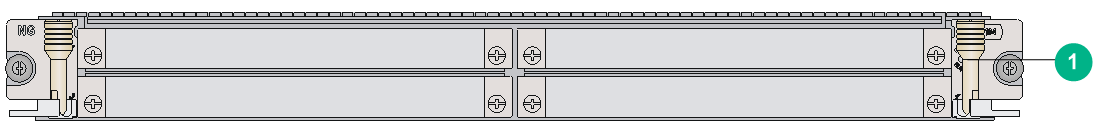
|
(1) Card status LED. For the LED description, see Table2-238. |
LEDs
|
LED |
Status |
Description |
|
RUN (Green) |
Steady on |
The card is faulty. |
|
Off |
The card is faulty or is not in position. |
|
|
Flashing (about once per second) |
The card is operating correctly. |
|
|
Fast flashing (about eight times per second) |
The card is starting up. If the LED keeps fast flashing, card registration has failed. |
Subcard slots
Table2-239 Subcard slots
|
Card model |
Number of subcard slots |
|
CMPE-1104 |
4 |
Technical specifications
Table2-240 Technical specifications
|
Item |
Description |
|
Dimensions (H × W × D) |
40 × 399 × 352 mm (1.57 × 15.71 × 13.86 in) |
|
Weight |
3.52 kg (7.76 lb) |
|
Maximum power consumption |
158 W |
|
Power consumption (with typical configuration) |
94 W |
|
Minimum power consumption |
91 W |
|
Operating temperature |
0°C to 45°C (32°F to 113°F) |
Configuration restrictions and guidelines
The subslot restrictions of a CMPE card depend on the subslot mode. For more information about subslot modes, see H3C CR16000-F Routers Configuration Guides.
Compatibility information
Table2-241 Compatibility matrix between CMPE cards and routers
|
Card model |
CR16006-F, CR16010-F, CR16014-F |
CR16010H-F (with five fabric modules), CR16018-F (with five fabric modules) |
CR16010H-F (with four fabric modules), CR16018-F (with four fabric modules) |
CR16010H-FA, CR16018-FA |
CR16003E-F, CR16005E-F, CR16010E-F |
|
CMPE-1104 |
Supported |
Not supported |
Not supported |
Not supported |
Not supported |
Table2-242 Compatibility matrix between CMPE cards and subcards
|
Subcard model |
CMPE cards |
|
GIC-CLP2L-G |
Not supported |
|
GIC-CQ1L-G |
Not supported |
|
GIC-ET16L-G |
Not supported |
|
GIC-GP12L-G |
Not supported |
|
GIC-TCP8L-G |
Not supported |
|
GIC-XP4L-G |
Not supported |
|
GIC-XP6L-G |
Not supported |
|
GIC-XP12L-G |
Not supported |
|
PIC-GP10L |
Not supported |
|
PIC-TCP8L |
Not supported |
|
PIC-PSP4L |
Not supported |
|
PIC-PS2G4L |
Not supported |
|
PIC-PUP1L |
Not supported |
|
PIC-XP1L |
Not supported |
|
MIC-GT20L |
Not supported |
|
MIC-GT20L1 |
Not supported |
|
MIC-GT20LA |
Not supported |
|
MIC-CLP4L |
Supported |
|
MIC-ET16L |
Supported |
|
MIC-CLP2L |
Supported |
|
MIC-SP8L |
Only one is supported. Can be installed only slot 1 or slot 2. |
|
MIC-SP4L |
Supported |
|
MIC-GP4L |
Supported |
|
MIC-GP8L |
Not supported in slot 3 or slot 4 |
|
MIC-GP10L1 |
Not supported |
|
MIC-GP10L2 |
Not supported |
|
MIC-GP10L-V2 |
Not supported |
|
MIC-GP10LA |
Not supported |
|
MIC-GP20L |
Not supported |
|
MIC-GP20L1 |
Not supported |
|
MIC-XP2L |
Not supported |
|
MIC-XP2L-LAN |
Not supported |
|
MIC-XP4L1 |
Not supported |
|
MIC-XP5L |
Not supported |
|
MIC-XP5L1 |
Not supported |
|
MIC-XP5L2 |
Not supported |
|
MIC-XP8L |
Not supported |
|
MIC-XP10LF |
Not supported |
|
MIC-XP10L-LAN |
Not supported |
|
MIC-XP20L |
Not supported |
|
MIC-XP20LA |
Not supported |
|
MIC-QP1L |
Not supported |
|
MIC-CP1L |
Not supported |
|
MIC-CP1L-V2 |
Not supported |
|
MIC-CP2L |
Not supported |
|
MIC-CP2L-V2 |
Not supported |
|
MIC-CQ1L1 |
Not supported |
|
MIC-CQ1L2 |
Not supported |
|
MIC-CQ1LF |
Not supported |
|
MIC-CQ2L |
Not supported |
|
MIC-CQ2LA |
Not supported |
|
MIC-PSP4L |
Not supported |
|
MIC-TCP8L |
Not supported |
|
MIC-SEC |
Not supported |
|
NIC-GT20L |
Not supported |
|
NIC-QP3L |
Not supported |
|
NIC-GP20L |
Not supported |
|
NIC-GP24L |
Not supported |
|
NIC-GP24L1 |
Not supported |
|
NIC-GP24L1A |
Not supported |
|
NIC-GP24L1A-G |
Not supported |
|
NIC-XP5L |
Not supported |
|
NIC-XP10L |
Not supported |
|
NIC-XP20L |
Not supported |
|
NIC-XP20L1 |
Not supported |
|
NIC-XP20L1A |
Not supported |
|
NIC-XP20L1A-G |
Not supported |
|
NIC-CC1L |
Not supported |
|
NIC-CC2L |
Not supported |
|
NIC-CQ1L |
Not supported |
|
NIC-CQ2L |
Not supported |
|
NIC-CQ2LA |
Not supported |
|
NIC-CQ2LA-G |
Not supported |
|
RX-NIC-GP20L |
Not supported |
|
RX-NIC-XP5L |
Not supported |
|
RX-NIC-XP10L |
Not supported |
|
RX-NIC-XP20L |
Not supported |
|
RX-NIC-YGS4L |
Not supported |
|
RX-NIC-LGQ2L |
Not supported |
|
RX-NIC-LGQ4L |
Not supported |
|
RX-NIC-CQ1LF |
Not supported |
|
RX-NIC-CQ2LF |
Not supported |
|
RX-NIC-CC1L |
Not supported |
|
RX-NIC-CC2L |
Not supported |
SPE base cards
RX-SPE200/RX-SPE200-E
View
Figure2-46 RX-SPE200 view
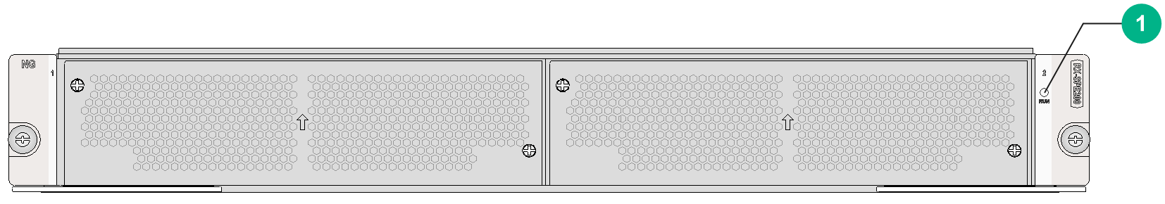
|
(1) Card status LED. For the LED description, see Table2-243. |
The views of the RX-SPE200 and RX-SPE200-E are similar. This figure uses the RX-SPE200 as an example.
LEDs
|
LED |
Status |
Description |
|
RUN (Green) |
Steady on |
The card is faulty. |
|
Off |
The card is faulty or is not in position. |
|
|
Flashing (about once per second) |
The card is operating correctly. |
|
|
Fast flashing (about eight times per second) |
The card is starting up. If the LED keeps fast flashing, card registration has failed. |
Subcard slots
Table2-244 Subcard slots
|
Card model |
Number of subcard slots |
|
RX-SPE200 |
2 |
|
RX-SPE200-E |
2 |
Technical specifications
Table2-245 Technical specifications
|
Item |
Description |
|
Dimensions (H × W × D) |
52.5 × 399 × 352 mm (2.07 × 15.71 × 13.86 in) |
|
Weight |
· RX-SPE200: 5.35 kg (11.79 lb) · RX-SPE200-E: 5.00 kg (11.02 lb) |
|
Maximum power consumption |
· RX-SPE200: 530 W · RX-SPE200-E: 270 W |
|
Power consumption (with typical configuration) |
· RX-SPE200: 300 W · RX-SPE200-E: 135 W |
|
Minimum power consumption |
· RX-SPE200: 280 W · RX-SPE200-E: 120 W |
|
Operating temperature |
0°C to 45°C (32°F to 113°F) |
Compatibility information
Table2-246 Compatibility matrix between SPE cards and routers
|
Card model |
CR16006-F, CR16010-F, CR16014-F |
CR16010H-F (with five fabric modules), CR16018-F (with five fabric modules) |
CR16010H-F (with four fabric modules), CR16018-F (with four fabric modules) |
CR16010H-FA, CR16018-FA |
CR16003E-F, CR16005E-F, CR16010E-F |
|
RX-SPE200 |
Not supported |
Supported |
Not supported |
Not supported |
Supported |
|
RX-SPE200-E |
Not supported |
Supported |
Not supported |
Not supported |
Not supported |
Table2-247 Compatibility matrix between SPE cards and subcards
|
Subcard model |
RX-SPE200 |
RX-SPE200-E |
|
GIC-CLP2L-G |
Not supported |
Not supported |
|
GIC-CQ1L-G |
Not supported |
Not supported |
|
GIC-ET16L-G |
Not supported |
Not supported |
|
GIC-GP12L-G |
Not supported |
Not supported |
|
GIC-TCP8L-G |
Not supported |
Not supported |
|
GIC-XP4L-G |
Not supported |
Not supported |
|
GIC-XP6L-G |
Not supported |
Not supported |
|
GIC-XP12L-G |
Not supported |
Not supported |
|
PIC-GP10L |
Not supported |
Not supported |
|
PIC-TCP8L |
Not supported |
Not supported |
|
PIC-PSP4L |
Not supported |
Not supported |
|
PIC-PS2G4L |
Not supported |
Not supported |
|
PIC-PUP1L |
Not supported |
Not supported |
|
PIC-XP1L |
Not supported |
Not supported |
|
MIC-GT20L |
Not supported |
Not supported |
|
MIC-GT20L1 |
Not supported |
Not supported |
|
MIC-GT20LA |
Not supported |
Not supported |
|
MIC-CLP4L |
Not supported |
Not supported |
|
MIC-ET16L |
Not supported |
Not supported |
|
MIC-CLP2L |
Not supported |
Not supported |
|
MIC-SP8L |
Not supported |
Not supported |
|
MIC-SP4L |
Not supported |
Not supported |
|
MIC-GP4L |
Not supported |
Not supported |
|
MIC-GP8L |
Not supported |
Not supported |
|
MIC-GP10L1 |
Not supported |
Not supported |
|
MIC-GP10L2 |
Not supported |
Not supported |
|
MIC-GP10L-V2 |
Not supported |
Not supported |
|
MIC-GP10LA |
Not supported |
Not supported |
|
MIC-GP20L |
Not supported |
Not supported |
|
MIC-GP20L1 |
Not supported |
Not supported |
|
MIC-XP2L |
Not supported |
Not supported |
|
MIC-XP2L-LAN |
Not supported |
Not supported |
|
MIC-XP4L1 |
Not supported |
Not supported |
|
MIC-XP5L |
Not supported |
Not supported |
|
MIC-XP5L1 |
Not supported |
Not supported |
|
MIC-XP5L2 |
Not supported |
Not supported |
|
MIC-XP8L |
Not supported |
Not supported |
|
MIC-XP10LF |
Not supported |
Not supported |
|
MIC-XP10L-LAN |
Not supported |
Not supported |
|
MIC-XP20L |
Not supported |
Not supported |
|
MIC-XP20LA |
Not supported |
Not supported |
|
MIC-QP1L |
Not supported |
Not supported |
|
MIC-CP1L |
Not supported |
Not supported |
|
MIC-CP1L-V2 |
Not supported |
Not supported |
|
MIC-CP2L |
Not supported |
Not supported |
|
MIC-CP2L-V2 |
Not supported |
Not supported |
|
MIC-CQ1L1 |
Not supported |
Not supported |
|
MIC-CQ1L2 |
Not supported |
Not supported |
|
MIC-CQ1LF |
Not supported |
Not supported |
|
MIC-CQ2L |
Not supported |
Not supported |
|
MIC-PSP4L |
Not supported |
Not supported |
|
MIC-TCP8L |
Not supported |
Not supported |
|
MIC-SEC |
Not supported |
Not supported |
|
NIC-GT20L |
Supported |
Not supported |
|
NIC-QP3L |
Supported |
Supported |
|
NIC-GP20L |
Supported |
Not supported |
|
NIC-GP24L |
Not supported |
Not supported |
|
NIC-GP24L1 |
Not supported |
Supported |
|
NIC-GP24L1A |
Not supported |
Not supported |
|
NIC-GP24L1A-G |
Not supported |
Not supported |
|
NIC-XP5L |
Not supported |
Not supported |
|
NIC-XP10L |
Supported |
Not supported |
|
NIC-XP20L |
Not supported |
Not supported |
|
NIC-XP20L1 |
Not supported |
Not supported |
|
NIC-XP20L1A |
Not supported |
Not supported |
|
NIC-XP20L1A-G |
Not supported |
Not supported |
|
NIC-CC1L |
Not supported |
Not supported |
|
NIC-CC2L |
Not supported |
Not supported |
|
NIC-CQ1L |
Supported |
Not supported |
|
NIC-CQ2L |
Not supported |
Not supported |
|
NIC-CQ2LA |
Not supported |
Not supported |
|
NIC-CQ2LA-G |
Not supported |
Not supported |
|
RX-NIC-GP20L |
Supported |
Not supported |
|
RX-NIC-XP5L |
Supported |
Supported |
|
RX-NIC-XP10L |
Supported |
Supported |
|
RX-NIC-XP20L |
Not supported |
Not supported |
|
RX-NIC-YGS4L |
Supported |
Supported |
|
RX-NIC-LGQ2L |
Supported |
Supported |
|
RX-NIC-LGQ4L |
Not supported |
Not supported |
|
RX-NIC-CQ1LF |
Supported |
Supported |
|
RX-NIC-CQ2LF |
Not supported |
Not supported |
|
RX-NIC-CC1L |
Supported |
Supported |
|
RX-NIC-CC2L |
Not supported |
Not supported |
GIC subcards
|
|
IMPORTANT: · To use a GIC interface card, you must install it on a CSPEX base card. You cannot install it directly on the router. · For the compatibility between GIC interface cards and CSPEX base cards, see the compatibility information for the base cards. · Some GIC subcards support changing the speed. For more information, see H3C CR16000-F Routers Configuration Guides. |
GIC-CLP2L-G
View
Figure2-47 GIC-CLP2L-G view
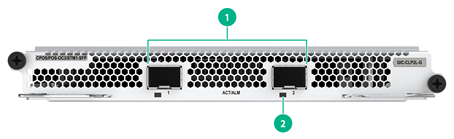
|
(1) OC-3/STM-1 SFP fiber ports (2 in total) |
(2) Port LED. For the LED description, see Table2-248. |
LEDs
Table2-248 WAN port LED description
|
LED |
Status |
Description |
|
WAN port LED (ACT/ALM) |
Flashing green |
The port is up and is receiving or sending data correctly. |
|
Steady green |
The port is up and no services are running on the port. |
|
|
Steady red |
An alarm has occurred. |
|
|
Off |
The port is down. |
Ports
Table2-249 Port specifications
|
Card model |
Description |
Connector type |
Port quantity |
Port transmission speed |
|
GIC-CLP2L-G |
2-port OC-3/STM-1 (155M) channelized POS optical interface card |
LC |
2 |
155 Mbps (OC-3/STM-1 ) |
Technical specifications
Table2-250 Technical specifications
|
Item |
Description |
|
Dimensions (H × W × D) |
22.3 × 190 × 154 mm (0.88 × 7.48 × 6.06 in) |
|
Weight |
1.05 kg (2.31 lb) |
|
Maximum power consumption |
18 W |
|
Minimum power consumption |
16 W |
|
Operating temperature |
0°C to 45°C (32°F to 113°F) |
GIC-CQ1L-G
View
Figure2-48 GIC-CQ1L-G view
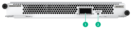
|
(1) 100GBASE-R QSFP28 fiber port (1 in total) |
(2) QSFP28 port LED. For the LED description, see Table2-251. |
LEDs
Table2-251 QSFP28 port LED description
|
LED |
Status |
Description |
|
QSFP28 port LED |
Flashing |
The QSFP28 port is receiving or sending data. |
|
On |
A link is present on the QSFP28 port. |
|
|
Off |
No link is present on the QSFP28 port. |
Ports
Table2-252 Port specifications
|
Card model |
Description |
Connector type |
Port quantity |
Port transmission speed |
|
GIC-CQ1L-G |
1-port 100G Ethernet optical interface card |
LC |
1 |
100 Gbps |
|
40 Gbps |
Technical specifications
Table2-253 Technical specifications
|
Item |
Description |
|
Dimensions (H × W × D) |
22.3 × 190 × 154 mm (0.88 × 7.48 × 6.06 in) |
|
Weight |
1.00 kg (2.20 lb) |
|
Maximum power consumption |
15 W |
|
Minimum power consumption |
13 W |
|
Operating temperature |
0°C to 45°C (32°F to 113°F) |
GIC-ET16L-G
View
Figure2-49 GIC-ET16L-G view
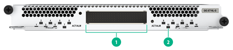
|
(1) E1-HM96 copper ports (16 in total) |
(2) Port LED. For the LED description, see Table2-254. |
LEDs
Table2-254 WAN port LED description
|
LED |
Status |
Description |
|
ACT/ALM |
Flashing green |
The port is receiving or sending data. |
|
Steady green |
A link is present, but the port is not receiving or sending data. |
|
|
Steady red |
An alarm has occurred. |
|
|
Off |
No link is present on the port. |
Ports
Table2-255 Port specifications
|
Card model |
Description |
Connector type |
Port quantity |
Port transmission speed |
|
GIC-ET16L-G |
16-port E1 copper interface card |
HM96 male connector |
16 |
E1 |
Technical specifications
Table2-256 Technical specifications
|
Item |
Description |
|
Dimensions (H × W × D) |
22.3 × 190 × 154 mm (0.88 × 7.48 × 6.06 in) |
|
Weight |
1.00 kg (2.20 lb) |
|
Maximum power consumption |
14 W |
|
Minimum power consumption |
12 W |
|
Operating temperature |
0°C to 45°C (32°F to 113°F) |
GIC-GP12L-G
View
Figure2-50 GIC-GP12L-G view
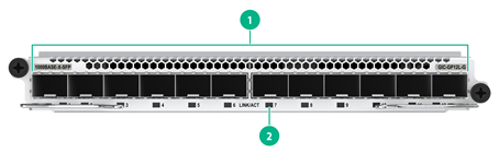
|
(1) 1000BASE-X SFP fiber ports (12 in total) |
(2) SFP port LED. For the LED description, see Table2-257. |
LEDs
Table2-257 GE SFP port LED description
|
LED |
Status |
Description |
|
GE SFP port LED (LINK/ACT) |
Flashing green |
The SFP port is receiving or sending data. |
|
Steady green |
A link is present on the SFP port. |
|
|
Off |
No link is present on the SFP port. |
Ports
Table2-258 Port specifications
|
Card model |
Description |
Connector type |
Port quantity |
Port transmission speed |
|
GIC-GP12L-G |
12-port 1000BASE-X Ethernet optical interface card |
LC |
12 |
100 Mbps |
|
1000 Mbps |
Technical specifications
Table2-259 Technical specifications
|
Item |
Description |
|
Dimensions (H × W × D) |
22.3 × 190 × 154 mm (0.88 × 7.48 × 6.06 in) |
|
Weight |
1.05 kg (2.31 lb) |
|
Maximum power consumption |
26 W |
|
Minimum power consumption |
15 W |
|
Operating temperature |
0°C to 45°C (32°F to 113°F) |
GIC-TCP8L-G
View
Figure2-51 GIC-TCP8L-G view
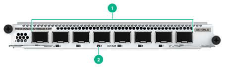
|
(1) OC-3c/OC-12c POS/GE fiber ports (8 in total) |
(2) Port LED. For the LED description, see Table2-260. |
LEDs
Table2-260 WAN port LED description
|
LED |
Status |
Description |
|
WAN port LED (ACT/ALM) |
Flashing green |
The port is up and is receiving or sending data correctly. |
|
Steady green |
The port is up and no services are running on the port. |
|
|
Steady red |
An alarm has occurred. |
|
|
Off |
The port is down. |
Ports
Table2-261 Port specifications
|
Card model |
Description |
Connector type |
Port quantity |
Port transmission speed |
|
GIC-TCP8L-G |
8-port OC-3c/OC-12c (622M/155M) POS/GE optical interface card |
LC |
8 |
100 Mbps |
|
155 Mbps (OC-3/STM-1 ) |
||||
|
622 Mbps (OC-12/STM-4) |
||||
|
1000 Mbps |
Technical specifications
Table2-262 Technical specifications
|
Item |
Description |
|
Dimensions (H × W × D) |
22.3 × 190 × 154 mm (0.88 × 7.48 × 6.06 in) |
|
Weight |
1.05 kg (2.31 lb) |
|
Maximum power consumption |
24 W |
|
Minimum power consumption |
16 W |
|
Operating temperature |
0°C to 45°C (32°F to 113°F) |
GIC-XP4L-G
View
Figure2-52 GIC-XP4L-G view
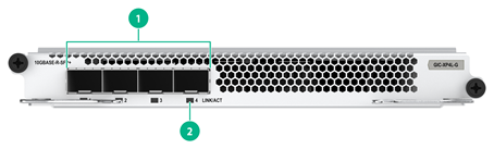
|
(1) 10GBASE-R/W SFP+ fiber ports (4 in total) |
(2) SFP+ port LED. For the LED description, see Table2-263. |
LEDs
Table2-263 SFP+ port LED description
|
LED |
Status |
Description |
|
10GE SFP+ port LED (LINK/ACT) |
Flashing |
The SFP+ port is receiving or sending data. |
|
On |
A link is present on the SFP+ port. |
|
|
Off |
No link is present on the SFP+ port. |
|
|
NOTE: You can identify the speed of an SFP+ port by observing the color of its LED. Green indicates a speed of 10 Gbps, and yellow indicates a speed of 1000 Mbps. |
Ports
Table2-264 Port specifications
|
Card model |
Description |
Connector type |
Port quantity |
Port transmission speed |
|
GIC-XP4L-G |
4-port 10GBASE-R/W Ethernet optical interface card |
LC |
4 |
100 Mbps |
|
1000 Mbps |
||||
|
10 Gbps |
Technical specifications
Table2-265 Technical specifications
|
Item |
Description |
|
Dimensions (H × W × D) |
22.3 × 190 × 154 mm (0.88 × 7.48 × 6.06 in) |
|
Weight |
1.05 kg (2.31 lb) |
|
Maximum power consumption |
23 W |
|
Minimum power consumption |
15 W |
|
Operating temperature |
0°C to 45°C (32°F to 113°F) |
GIC-XP6L-G
View
Figure2-53 GIC-XP6L-G view
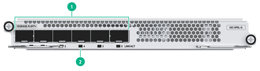
|
(1) 10GBASE-R/W SFP+ fiber ports (6 in total) |
(2) SFP+ port LED. For the LED description, see Table2-266. |
LEDs
Table2-266 SFP+ port LED description
|
LED |
Status |
Description |
|
10GE SFP+ port LED (LINK/ACT) |
Flashing |
The SFP+ port is receiving or sending data. |
|
On |
A link is present on the SFP+ port. |
|
|
Off |
No link is present on the SFP+ port. |
|
|
NOTE: You can identify the speed of an SFP+ port by observing the color of its LED. Green indicates a speed of 10 Gbps, and yellow indicates a speed of 1000 Mbps. |
Ports
Table2-267 Port specifications
|
Card model |
Description |
Connector type |
Port quantity |
Port transmission speed |
|
GIC-XP6L-G |
6-port 10GBASE-R/W Ethernet optical interface card |
LC |
6 |
100 Mbps |
|
1000 Mbps |
||||
|
10 Gbps |
Technical specifications
Table2-268 Technical specifications
|
Item |
Description |
|
Dimensions (H × W × D) |
22.3 × 190 × 154 mm (0.88 × 7.48 × 6.06 in) |
|
Weight |
1.05 kg (2.31 lb) |
|
Maximum power consumption |
24 W |
|
Minimum power consumption |
15 W |
|
Operating temperature |
0°C to 45°C (32°F to 113°F) |
GIC-XP12L-G
View
Figure2-54 GIC-XP12L-G view
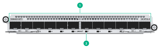
|
(1) 10GBASE-R/W SFP+ fiber ports (12 in total) |
(2) SFP+ port LED. For the LED description, see Table2-269. |
LEDs
Table2-269 SFP+ port LED description
|
LED |
Status |
Description |
|
10GE SFP+ port LED (LINK/ACT) |
Flashing |
The SFP+ port is receiving or sending data. |
|
On |
A link is present on the SFP+ port. |
|
|
Off |
No link is present on the SFP+ port. |
|
|
NOTE: You can identify the speed of an SFP+ port by observing the color of its LED. Green indicates a speed of 10 Gbps, and yellow indicates a speed of 1000 Mbps. |
Ports
Table2-270 Port specifications
|
Card model |
Description |
Connector type |
Port quantity |
Port transmission speed |
|
GIC-XP12L-G |
12-port 10GBASE-R/W Ethernet optical interface card |
LC |
12 |
100 Mbps |
|
1000 Mbps |
||||
|
10 Gbps |
Technical specifications
Table2-271 Technical specifications
|
Item |
Description |
|
Dimensions (H × W × D) |
22.3 × 190 × 154 mm (0.88 × 7.48 × 6.06 in) |
|
Weight |
1.05 kg (2.31 lb) |
|
Maximum power consumption |
28 W |
|
Minimum power consumption |
15 W |
|
Operating temperature |
0°C to 45°C (32°F to 113°F) |
MIC subcards
|
|
IMPORTANT: · To use a MIC interface card, you must install it on a CMPE, SPE, or CSPEX base card. You cannot install it directly on the router. · For the compatibility between MIC interface cards and CMPE, SPE, or CSPEX base cards, see the compatibility information for the base cards. · A combo interface is a logical interface that contains an SFP port and an RJ-45 Ethernet port. Only one of them can be activated at a time. · Some MIC subcards support changing the speed. For more information, see H3C CR16000-F Routers Configuration Guides. |
MIC-CLP2L
View
Figure2-55 MIC-CLP2L view
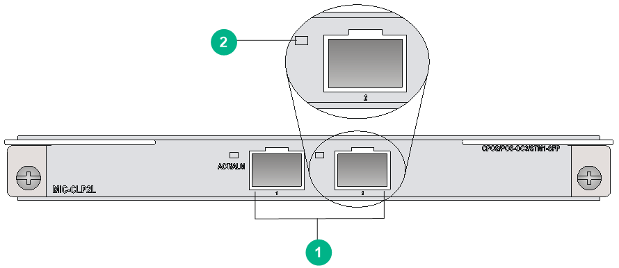
|
(1) CPOS-OC3/STM1-SFP ports (2 in total) |
(2) Port LED. For the LED description, see Table2-272. |
LEDs
Table2-272 WAN port LED description
|
LED |
Status |
Description |
|
WAN port LED (ACT/ALM) |
Flashing green |
The port is up and is receiving or sending data correctly. |
|
Steady green |
The port is up and no services are running on the port. |
|
|
Steady red |
An alarm has occurred. |
|
|
Off |
The port is down. |
Ports
Table2-273 Port specifications
|
Card model |
Description |
Connector type |
Port quantity |
Port transmission speed |
|
MIC-CLP2L |
2-port OC-3/STM-1 CPOS optical interface card |
LC |
2 |
155 Mbps (OC-3/STM-1 ) |
Technical specifications
Table2-274 Technical specifications
|
Item |
Description |
|
Dimensions (H × W × D) |
18 × 171 × 157 mm (0.71 × 6.73 × 6.18 in) |
|
Weight |
0.32 kg (0.71 lb) |
|
Maximum power consumption |
10.9 W |
|
Minimum power consumption |
9.8 W |
|
Operating temperature |
0°C to 45°C (32°F to 113°F) |
MIC-CLP4L
View
Figure2-56 MIC-CLP4L view
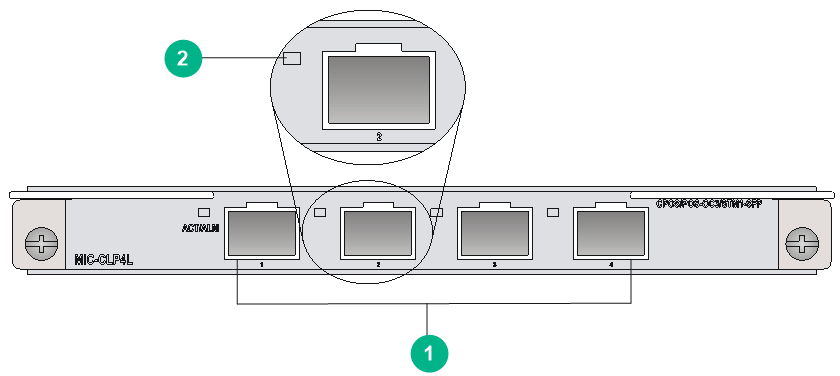
|
(1) CPOS-OC3/STM1-SFP ports (4 in total) |
(2) Port LED. For the LED description, see Table2-275. |
LEDs
Table2-275 WAN port LED description
|
LED |
Status |
Description |
|
WAN port LED (ACT/ALM) |
Flashing green |
The port is up and is receiving or sending data correctly. |
|
Steady green |
The port is up and no services are running on the port. |
|
|
Steady red |
An alarm has occurred. |
|
|
Off |
The port is down. |
Ports
Table2-276 Port specifications
|
Card model |
Description |
Connector type |
Port quantity |
Port transmission speed |
|
MIC-CLP4L |
4-port OC-3/STM-1 CPOS optical interface card |
LC |
4 |
155 Mbps (OC-3/STM-1) |
Technical specifications
Table2-277 Technical specifications
|
Item |
Description |
|
Dimensions (H × W × D) |
18 × 171 × 157 mm (0.71 × 6.73 × 6.18 in) |
|
Weight |
0.30 kg (0.66 lb) |
|
Maximum power consumption |
12.9 W |
|
Minimum power consumption |
9.8 W |
|
Operating temperature |
0°C to 45°C (32°F to 113°F) |
MIC-CP1L
View
Figure2-57 MIC-CP1L view

|
(1) 100GBASE-R-CFP fiber port (1 in total) |
(2) CFP port LED. For the LED description, see Table2-278 |
LEDs
Table2-278 CFP port LED description
|
LED |
Status |
Description |
|
CFP port LED |
Flashing |
The CFP port is sending or receiving data. |
|
Steady on |
A link is present on the CFP port. |
|
|
Off |
No link is present on the CFP port. |
Ports
Table2-279 Port specifications
|
Card model |
Description |
Connector type |
Port quantity |
Port transmission speed |
|
MIC-CP1L |
1-port 100G optical interface card (CFP, LC) |
LC |
1 |
100 Gbps |
Technical specifications
Table2-280 Technical specifications
|
Item |
Description |
|
Dimensions (H × W × D) |
37 × 171 × 157 mm (1.46 × 6.73 × 6.18 in) |
|
Weight |
0.55 kg (1.21 lb) |
|
Maximum power consumption |
11.8 W |
|
Minimum power consumption |
3.3 W |
|
Operating temperature |
0°C to 45°C (32°F to 113°F) |
MIC-CP1L-V2
View
Figure2-58 MIC-CP1L-V2 view
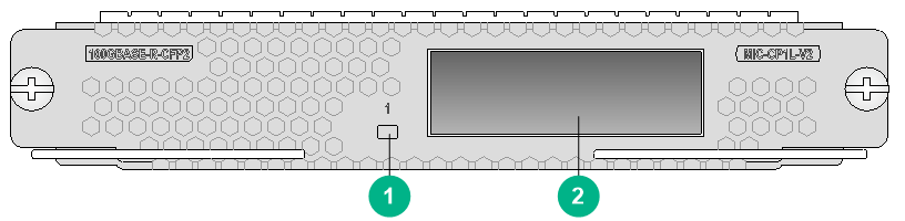
|
(1) CFP2 port LED. For the LED description, see Table2-281. |
(2) 100GBASE-R-CFP2 fiber port (1 in total) |
LEDs
Table2-281 CFP2 port LED description
|
LED |
Status |
Description |
|
CFP2 port LED |
Flashing |
The CFP2 port is sending or receiving data at 100 Gbps. |
|
Steady on |
A 100 Gbps link is present on the CFP2 port. |
|
|
Off |
No link is present on the CFP2 port. |
Ports
Table2-282 Port specifications
|
Card model |
Description |
Connector type |
Port quantity |
Port transmission speed |
|
MIC-CP1L-V2 |
1-port 100G Ethernet optical interface card (CFP2, LC) |
LC |
1 |
100 Gbps |
Technical specifications
Table2-283 Technical specifications
|
Item |
Description |
|
Dimensions (H × W × D) |
23 × 137 × 119 mm (0.91 × 5.39 × 4.69 in) |
|
Weight |
0.45 kg (0.99 lb) |
|
Maximum power consumption |
8.7 W |
|
Minimum power consumption |
6 W |
|
Operating temperature |
0°C to 45°C (32°F to 113°F) |
MIC-CP2L
View
Figure2-59 MIC-CP2L view
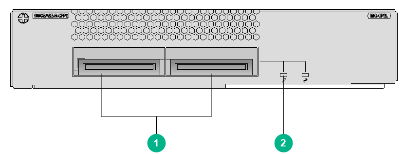
|
(1) 100GBASE-R-CFP2 fiber ports (2 in total) (100G CFP2 modules supported) |
(2) CFP2 port LED. For the LED description, see Table2-284. |
LEDs
Table2-284 CFP2 port LED description
|
LED |
Status |
Description |
|
CFP2 port LED |
Flashing |
The CFP2 port is sending or receiving data at 100 Gbps. |
|
Steady on |
A 100 Gbps link is present on the CFP2 port. |
|
|
Off |
No link is present on the CFP2 port. |
Ports
Table2-285 Port specifications
|
Card model |
Description |
Connector type |
Port quantity |
Port transmission speed |
|
MIC-CP2L |
2-port 100G Ethernet optical interface card (CFP2, LC) |
LC |
2 |
100 Gbps |
Technical specifications
Table2-286 Technical specifications
|
Item |
Description |
|
Dimensions (H × W × D) |
38 × 179 × 149 mm (1.50 × 7.05 × 5.87 in) |
|
Weight |
0.80 kg (1.76 lb) |
|
Maximum power consumption |
18.1 W |
|
Minimum power consumption |
8.6 W |
|
Operating temperature |
0°C to 45°C (32°F to 113°F) |
MIC-CP2L-V2
View
Figure2-60 MIC-CP2L-V2 view
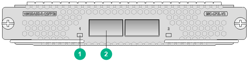
|
(1) QSFP28 port LED. For the LED description, see Table2-287. |
(2) 100GBASE-R-QSFP28 fiber ports (2 in total) |
LEDs
Table2-287 QSFP28 port LED description
|
LED |
Status |
Description |
|
QSFP28 port LED |
Flashing |
The QSFP28 port is sending or receiving data at 100 Gbps. |
|
Steady on |
A 100 Gbps link is present on the QSFP28 port. |
|
|
Off |
No link is present on the QSFP28 port. |
Ports
Table2-288 Port specifications
|
Card model |
Description |
Connector type |
Port quantity |
Port transmission speed |
|
MIC-CP2L-V2 |
2-port 100G Ethernet optical interface card (QSFP28) |
LC |
2 |
100 Gbps |
Technical specifications
Table2-289 Technical specifications
|
Item |
Description |
|
Dimensions (H × W × D) |
23 × 137 × 119 mm (0.91 × 5.39 × 4.69 in) |
|
Weight |
0.40 kg (0.88 lb) |
|
Maximum power consumption |
15 W |
|
Minimum power consumption |
9.3 W |
|
Operating temperature |
0°C to 45°C (32°F to 113°F) |
MIC-CQ1L1
View
Figure2-61 MIC-CQ1L1 view
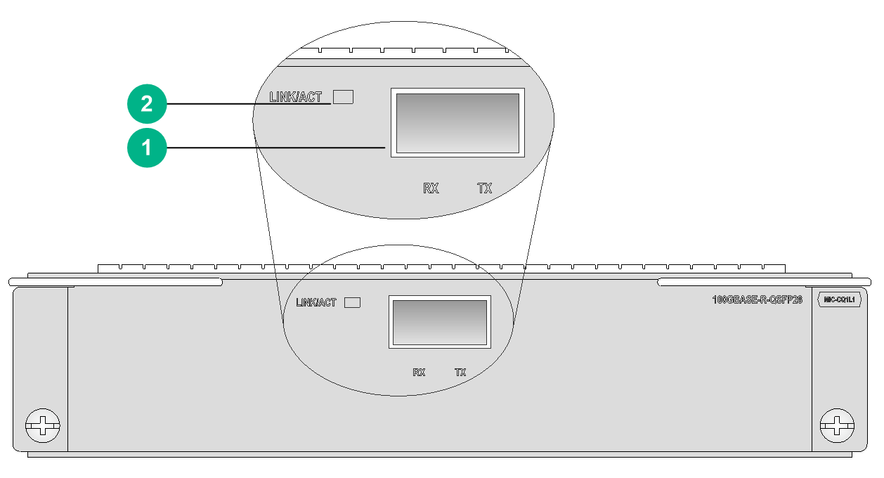
|
(1) 100GBASE-R-QSFP28 port (1 in total) |
(2) QSFP28 port LED. For the LED description, see Table2-290 |
LEDs
Table2-290 QSFP28 port LED description
|
LED |
Status |
Description |
|
QSFP28 port LED |
Flashing |
The QSFP28 port is sending or receiving data at 100 Gbps. |
|
Steady on |
A 100 Gbps link is present on the QSFP28 port. |
|
|
Off |
No link is present on the QSFP28 port. |
Ports
Table2-291 Port specifications
|
Card model |
Description |
Connector type |
Port quantity |
Port transmission speed |
|
MIC-CQ1L1 |
1-port 100G Ethernet optical interface card |
LC |
1 |
100 Gbps |
|
40 Gbps |
Technical specifications
Table2-292 Technical specifications
|
Item |
Description |
|
Dimensions (H × W × D) |
37 × 171 × 157 mm (1.46 × 6.73 × 6.18 in) |
|
Weight |
0.50 kg (1.10 lb) |
|
Maximum power consumption |
15 W |
|
Minimum power consumption |
9 W |
|
Operating temperature |
0°C to 45°C (32°F to 113°F) |
MIC-CQ1L2
View
Figure2-62 MIC-CQ1L2 view

|
(1) QSFP28 port LED. For the LED description, see Table2-293. |
(2) 100GBASE-R-QSFP28 fiber port (1 in total) |
LEDs
Table2-293 QSFP28 port LED description
|
LED |
Status |
Description |
|
QSFP28 port LED |
Flashing |
The QSFP28 port is sending or receiving data at 100 Gbps. |
|
Steady on |
A 100 Gbps link is present on the QSFP28 port. |
|
|
Off |
No link is present on the QSFP28 port. |
Ports
Table2-294 Port specifications
|
Card model |
Description |
Connector type |
Port quantity |
Port transmission speed |
|
MIC-CQ1L2 |
1-port 100G Ethernet optical interface card |
LC |
1 |
100 Gbps |
|
40 Gbps |
Technical specifications
Table2-295 Technical specifications
|
Item |
Description |
|
Dimensions (H × W × D) |
18 × 171 × 157 mm (0.71 × 6.73 × 6.18 in) |
|
Weight |
0.45 kg (0.99 lb) |
|
Maximum power consumption |
15 W |
|
Minimum power consumption |
9 W |
|
Operating temperature |
0°C to 45°C (32°F to 113°F) |
MIC-CQ1LF
View
Figure2-63 MIC-CQ1LF view
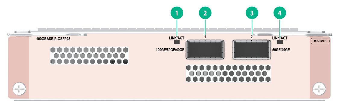
|
(1) 100G/50G/40G fiber port LED. For the LED description, see Table2-296. |
(2) 100G/50G/40G fiber port (1 in total) |
|
(3) 50G/40G fiber port (1 in total) |
(4) 50G/40G fiber port LED. For the LED description, see Table2-296. |
LEDs
Table2-296 Fiber port LED description
|
LED |
Status |
Description |
|
Fiber port LED |
Flashing |
The port is sending or receiving data. |
|
Steady on |
A link is present on the port. |
|
|
Off |
No link is present on the port. |
Ports
Table2-297 Port specifications
|
Card model |
Description |
Connector type |
Port quantity |
Port transmission speed |
|
MIC-CQ1LF |
2-port 50G/1-port 100G flexible Ethernet optical interface card (QSFP28,LC) |
LC |
2 |
· 100 Gbps · 50 Gbps · 40 Gbps |
Technical specifications
Table2-298 Technical specifications
|
Item |
Description |
|
Dimensions (H × W × D) |
36 × 171 × 157 mm (1.42 × 6.73 × 6.18 in) |
|
Weight |
0.58 kg (1.28 lb) |
|
Maximum power consumption |
27 W |
|
Minimum power consumption |
21 W |
|
Operating temperature |
0°C to 45°C (32°F to 113°F) |
MIC-CQ2L
View
Figure2-64 MIC-CQ2L view
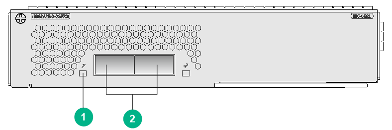
|
(1) QSFP28 port LED. For the LED description, see Table2-299. |
(2) 100GBASE-R-QSFP28 fiber ports (2 in total) |
LEDs
Table2-299 QSFP28 port LED description
|
LED |
Status |
Description |
|
QSFP28 port LED |
Flashing |
The QSFP28 port is sending or receiving data at 100 Gbps. |
|
Steady on |
A 100 Gbps link is present on the QSFP28 port. |
|
|
Off |
No link is present on the QSFP28 port. |
Ports
Table2-300 Port specifications
|
Card model |
Description |
Connector type |
Port quantity |
Port transmission speed |
|
MIC-CQ2L |
2-port 100G Ethernet optical interface card (QSFP28) |
LC |
2 |
100 Gbps |
|
40 Gbps |
Technical specifications
Table2-301 Technical specifications
|
Item |
Description |
|
Dimensions (H × W × D) |
38 × 179 × 149 mm (1.50 × 7.05 × 5.87 in) |
|
Weight |
0.40 kg (0.88 lb) |
|
Maximum power consumption |
16 W |
|
Minimum power consumption |
8 W |
|
Operating temperature |
0°C to 45°C (32°F to 113°F) |
MIC-ET16L
View
Figure2-65 MIC-ET16L view
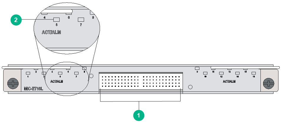
|
(1) E1-HM96 copper ports (16 in total) |
(2) Port LED. For the LED description, see Table2-302. |
LED
|
LED |
Status |
Description |
|
ACT/ALM |
Flashing green |
The port is sending or receiving data. |
|
Steady green |
A link is present, but the port is not receiving or sending data. |
|
|
Steady red |
An alarm has occurred. |
|
|
Off |
No link is present on the port. |
Ports
Table2-303 Port specifications
|
Card model |
Description |
Connector type |
Port quantity |
Port transmission speed |
|
MIC-ET16L |
16-port E1 electrical interface card (HM96 male connector) |
HM96 male |
16 |
E1 |
Technical specifications
Table2-304 Technical specifications
|
Item |
Description |
|
Dimensions (H × W × D) |
18 × 171 × 157 mm (0.71 × 6.73 × 6.18 in) |
|
Weight |
0.30 kg (0.66 lb) |
|
Maximum power consumption |
8.7 W |
|
Minimum power consumption |
8.6 W |
|
Operating temperature |
0°C to 45°C (32°F to 113°F) |
MIC-GP10L1/MIC-GP10L2
View
Figure2-66 MIC-GP10L1 view
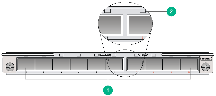
|
(1) 1000BASE-X-SFP fiber ports (10 in total) |
(2) SFP port LED. For the LED description, see Table2-305. |
The views of the MIC-GP10L1 and MIC-GP10L2 are similar. This figure uses the MIC-GP10L1 as an example.
LEDs
Table2-305 GE SFP port LED description
|
LED |
Status |
Description |
|
GE SFP port LED (LINK/ACT) |
Flashing green |
The SFP port is sending or receiving data. |
|
Green |
A link is present on the SFP port. |
|
|
Off |
No link is present on the SFP port. |
Ports
Table2-306 Port specifications
|
Card model |
Description |
Connector type |
Port quantity |
Port transmission speed |
|
MIC-GP10L1 |
10-port 1000BASE-X optical interface card (SFP, LC) |
LC |
10 |
100 Mbps |
|
1000 Mbps |
||||
|
MIC-GP10L2 |
10-port 1000BASE-X Ethernet optical interface card (SFP, LC) |
LC |
10 |
100 Mbps |
|
1000 Mbps |
Technical specifications
Table2-307 Technical specifications
|
Item |
Description |
|
Dimensions (H × W × D) |
18 × 171 × 157 mm (0.71 × 6.73 × 6.18 in) |
|
Weight |
· MIC-GP10L1: 0.30 kg (0.66 lb) · MIC-GP10L2: 0.48 kg (1.06 lb) |
|
Maximum power consumption |
· MIC-GP10L1: 7.9 W · MIC-GP10L2: 30 W |
|
Minimum power consumption |
· MIC-GP10L1: 2.1 W · MIC-GP10L2: 20 W |
|
Operating temperature |
0°C to 45°C (32°F to 113°F) |
MIC-GP10LA/MIC-GP10L-V2
View
Figure2-67 MIC-GP10L-V2 view
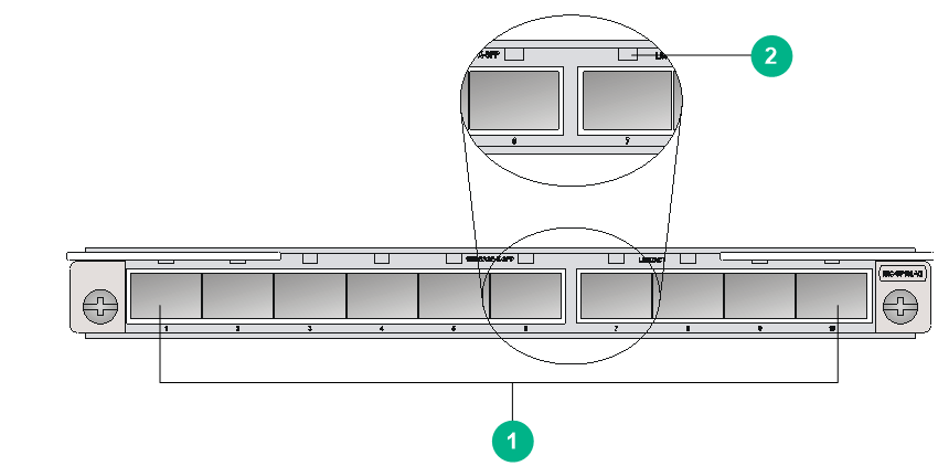
|
(1) 1000BASE-X-SFP fiber ports (10 in total) |
(2) SFP port LED. For the LED description, see Table2-308. |
The views of MIC-GP10LA and MIC-GP10L-V2 are similar. This figure uses the MIC-GP10L-V2 as an example.
LEDs
Table2-308 GE SFP port LED description
|
LED |
Status |
Description |
|
GE SFP port LED (LINK/ACT) |
Flashing green |
The SFP port is sending or receiving data. |
|
Green |
A link is present on the SFP port. |
|
|
Off |
No link is present on the SFP port. |
Ports
Table2-309 Port specifications
|
Card model |
Description |
Connector type |
Port quantity |
Port transmission speed |
|
MIC-GP10LA |
10-port 1000BASE-X Ethernet optical interface card A (SFP, LC) |
LC |
10 |
100 Mbps |
|
1000 Mbps |
||||
|
MIC-GP10L-V2 |
10-port 1000BASE-X Ethernet optical interface card (SFP, LC) |
LC |
10 |
100 Mbps |
|
1000 Mbps |
Technical specifications
Table2-310 Technical specifications
|
Item |
Description |
|
Dimensions (H × W × D) |
18 × 171 × 157 mm (0.71 × 6.73 × 6.18 in) |
|
Weight |
0.35 kg (0.77 lb) |
|
Maximum power consumption |
9.4 W |
|
Minimum power consumption |
9.3 W |
|
Operating temperature |
0°C to 45°C (32°F to 113°F) |
MIC-GP20L
View
Figure2-68 MIC-GP20L view
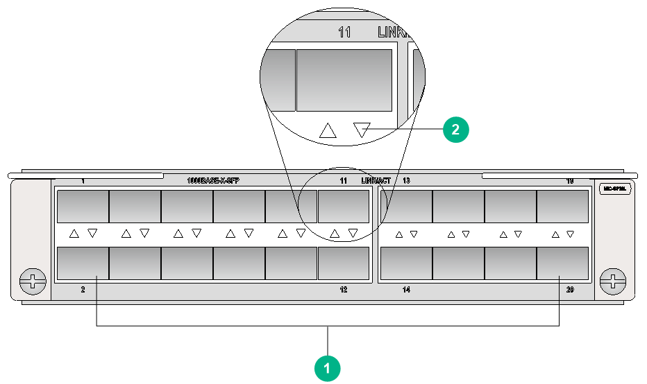
|
(1) 1000BASE-X-SFP fiber ports (20 in total) |
(2) SFP port LED. For the LED description, see Table2-311. |
LEDs
Table2-311 GE SFP port LED description
|
LED |
Status |
Description |
|
GE SFP port LED (LINK/ACT) |
Flashing green |
The SFP port is sending or receiving data. |
|
Green |
A link is present on the SFP port. |
|
|
Off |
No link is present on the SFP port. |
Ports
Table2-312 Port specifications
|
Card model |
Description |
Connector type |
Port quantity |
Port transmission speed |
|
MIC-GP20L |
20-port 1000BASE-X Ethernet optical interface card (SFP, LC) |
LC |
20 |
100 Mbps |
|
1000 Mbps |
Technical specifications
Table2-313 Technical specifications
|
Item |
Description |
|
Dimensions (H × W × D) |
37 × 171 × 157 mm (1.46 × 6.73 × 6.18 in) |
|
Weight |
0.55 kg (1.21 lb) |
|
Maximum power consumption |
23 W |
|
Minimum power consumption |
7.6 W |
|
Operating temperature |
0°C to 45°C (32°F to 113°F) |
MIC-GP20L1
View
Figure2-69 MIC-GP20L1 view

|
(1) 1000BASE-X-SFP fiber ports (20 in total) |
(2) SFP port LED. For the LED description, see Table2-314. |
LEDs
Table2-314 GE SFP port LED description
|
LED |
Status |
Description |
|
GE SFP port LED (LINK/ACT) |
Flashing green |
The SFP port is sending or receiving data. |
|
Green |
A link is present on the SFP port. |
|
|
Off |
No link is present on the SFP port. |
Ports
Table2-315 Port specifications
|
Card model |
Description |
Connector type |
Port quantity |
Port transmission speed |
|
MIC-GP20L1 |
20-port 1000BASE-X Ethernet optical interface card (SFP, LC) |
LC |
20 |
100 Mbps |
|
1000 Mbps |
Technical specifications
Table2-316 Technical specifications
|
Item |
Description |
|
Dimensions (H × W × D) |
38 × 179 × 149 mm (1.50 × 7.05 × 5.87 in) |
|
Weight |
0.80 kg (1.76 lb) |
|
Maximum power consumption |
18 W |
|
Minimum power consumption |
7 W |
|
Operating temperature |
0°C to 45°C (32°F to 113°F) |
MIC-GP4L
View
Table2-317 MIC-GP4L view
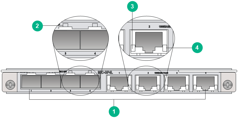
|
(1) Combo interfaces (4 in total) |
(2) Combo fiber port LINK/ACT LED. For the LED description, see Table2-318. |
|
(3) Combo copper LINK LED. For the LED description, see Table2-318. |
(4) Combo copper ACT LED. For the LED description, see Table2-318. |
LEDs
Table2-318 Combo ports LED description
|
Port type |
LED |
Status |
Description |
|
Combo fiber port |
LINK/ACT |
Steady on |
The port is up. |
|
Flashing green |
The port is receiving or sending data correctly. |
||
|
Off |
The port is down. |
||
|
Combo copper port |
LINK (Green) |
Steady on |
The port is up. |
|
Off |
The port is down. |
||
|
ACT (Orange) |
Flashing green |
The port is receiving or sending data correctly. |
|
|
Off |
The port is not receiving or sending data. |
Ports
Table2-319 Port specifications
|
Card model |
Description |
Connector type |
Port quantity |
Port transmission speed |
|
MIC-GP4L |
4-port 1000BASE-X/1000BASE-T combo interface card |
RJ45 |
4 |
10/100/1000 Mbps |
|
LC |
4 |
100 Mbps |
||
|
1000 Mbps |
Technical specifications
Table2-320 Technical specifications
|
Item |
Description |
|
Dimensions (H × W × D) |
18 × 171 × 157 mm (0.71 × 6.73 × 6.18 in) |
|
Weight |
0.31 kg (0.68 lb) |
|
Maximum power consumption |
5.5 W |
|
Minimum power consumption |
0.8 W |
|
Operating temperature |
0°C to 45°C (32°F to 113°F) |
MIC-GP8L
View
Figure2-70 MIC-GP8L view
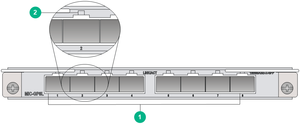
|
(1) 1000BASE-X-SFP fiber ports (8 in total) |
(2) SFP port LED. For the LED description, see Table2-321. |
LEDs
Table2-321 GE SFP port LED description
|
LED |
Status |
Description |
|
GE SFP port LED (LINK/ACT) |
Flashing green |
The SFP port is sending or receiving data. |
|
Green |
A link is present on the SFP port. |
|
|
Off |
No link is present on the SFP port. |
Ports
Table2-322 Port specifications
|
Card model |
Description |
Connector type |
Port quantity |
Port transmission speed |
|
MIC-GP8L |
8-port 1000BASE-X optical interface card (SFP, LC) |
LC |
8 |
100 Mbps |
|
1000 Mbps |
Technical specifications
Table2-323 Technical specifications
|
Item |
Description |
|
Dimensions (H × W × D) |
18 × 171 × 157 mm (0.71 × 6.73 × 6.18 in) |
|
Weight |
0.29 kg (0.64 lb) |
|
Maximum power consumption |
4.7 W |
|
Minimum power consumption |
0.6 W |
|
Operating temperature |
0°C to 45°C (32°F to 113°F) |
MIC-GT20L/MIC-GT20L1/MIC-GT20LA
View
Figure2-71 MIC-GT20L view
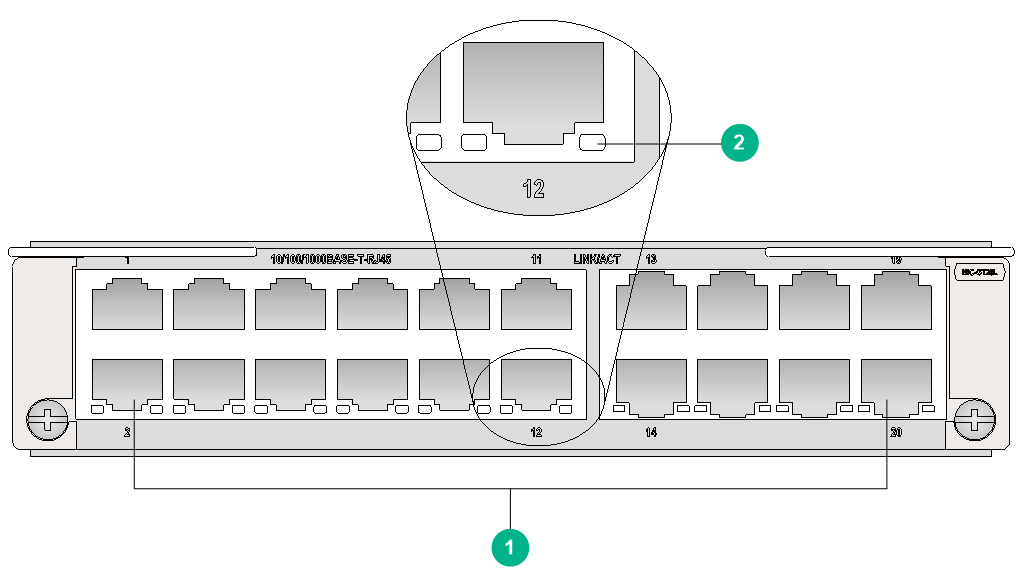
|
(1) 10/100/1000BASE-T copper ports (20 in total) |
(2) RJ-45 Ethernet port LED. For the description for the RJ-45 port LEDs on the MIC-GT20L and MIC-GT20LA, see Table2-324. For the description for the RJ-45 port LEDs on the MIC-GT20L1, see Table2-325. |
The views of the MIC-GT20L, MIC-GT20L1, and MIC-GT20LA are similar. This figure uses the MIC-GT20L as an example.
LEDs
Table2-324 RJ-45 Ethernet port LED description (1)
|
LED |
Status |
Description |
|
RJ-45 Ethernet port LED |
Flashing |
The port is sending or receiving data. |
|
Steady on |
A link is present on the port. |
|
|
Off |
No link is present on the port. |
Table2-325 RJ-45 Ethernet port LED description (2)
|
LED |
Status |
Description |
|
RJ-45 Ethernet port LED |
Flashing green |
The port is receiving or sending data at 1000 Mbps. |
|
Steady green |
A link is present on the port, and the port operates at 1000 Mbps. |
|
|
Flashing yellow |
The port is receiving or sending data at 10/100 Mbps. |
|
|
Steady yellow |
A link is present on the port, and the port operates at 10/100 Mbps. |
|
|
Off |
No link is present on the port. |
Ports
Table2-326 Port specifications
|
Card model |
Description |
Connector type |
Port quantity |
Port transmission speed |
|
MIC-GT20L |
20-port 1000BASE-X Ethernet electrical interface card (RJ45) |
RJ-45 |
20 |
10/100/1000 Mbps |
|
MIC-GT20L1 |
20-port 1000BASE-T Ethernet copper interface card (RJ45) |
RJ-45 |
20 |
10/100/1000 Mbps |
|
MIC-GT20LA |
20-port 1000BASE-X Ethernet electrical interface card A (RJ45) |
RJ-45 |
20 |
10/100/1000 Mbps |
Technical specifications
Table2-327 Technical specifications
|
Item |
Description |
|
Dimensions (H × W × D) |
37 × 171 × 157 mm (1.46 × 6.73 × 6.18 in) |
|
Weight |
· MIC-GT20L: 0.50 kg (1.10 lb) · MIC-GT20LA: 0.84 kg (1.85 lb) · MIC-GT20L1: 0.40 kg (0.88 lb) |
|
Maximum power consumption |
· MIC-GT20L, MIC-GT20LA: 11.9 W · MIC-GT20L1: 39 W |
|
Minimum power consumption |
· MIC-GT20L, MIC-GT20LA: 9.2 W · MIC-GT20L1: 28 W |
|
Operating temperature |
0°C to 45°C (32°F to 113°F) |
MIC-PSP4L
View
Figure2-72 MIC-PSP4L view
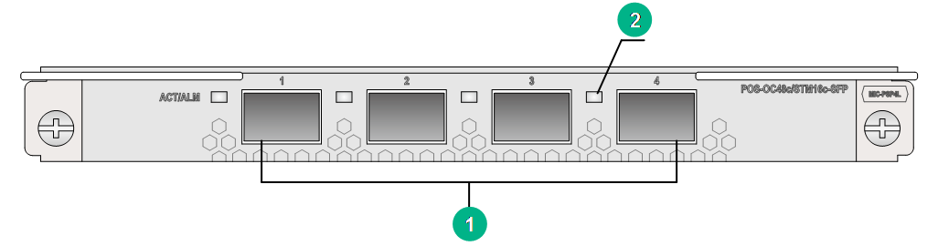
|
(1) OC-48c/STM-16c POS fiber ports (4 in total) |
(2) Port LED. For the LED description, see Table2-328. |
LEDs
Table2-328 WAN port LED description
|
LED |
Status |
Description |
|
WAN port LED (ACT/ALM) |
Flashing green |
The port is up and is receiving or sending data correctly. |
|
Steady green |
The port is up and no services are running on the port. |
|
|
Steady red |
An alarm has occurred. |
|
|
Off |
The port is down. |
Ports
Table2-329 Port specifications
|
Card model |
Description |
Connector type |
Port quantity |
Port transmission speed |
|
MIC-PSP4L |
4-port OC-48c/STM-16c POS optical interface card (SFP, LC) |
LC |
4 |
2.5 Gbps |
Technical specifications
Table2-330 Technical specifications
|
Item |
Description |
|
Dimensions (H × W × D) |
18 × 171 × 157 mm (0.71 × 6.73 × 6.18 in) |
|
Weight |
0.40 kg (0.88 lb) |
|
Maximum power consumption |
33 W |
|
Minimum power consumption |
29 W |
|
Operating temperature |
0°C to 45°C (32°F to 113°F) |
MIC-QP1L
View
Figure2-73 MIC-QP1L view
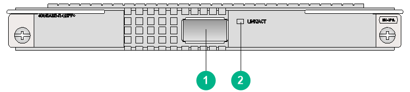
|
(1) 40GBASE-R-QSFP+ fiber port (1 in total) |
(2) QSFP+ port LED. For the LED description, see Table2-331. |
LEDs
Table2-331 QSFP+ port LED description
|
LED |
Status |
Description |
|
QSFP+ port LED |
Flashing |
The QSFP+ port is sending or receiving data. |
|
Steady on |
A link is present on the QSFP+ port. |
|
|
Off |
No link is present on the QSFP+ port. |
Ports
Table2-332 Port specifications
|
Card model |
Description |
Connector type |
Port quantity |
Port transmission speed |
|
MIC-QP1L |
1-port 40G Ethernet optical interface card (QSFP+, LC) |
LC |
1 |
40 Gbps |
|
4 |
10 Gbps |
Technical specifications
Table2-333 Technical specifications
|
Item |
Description |
|
Dimensions (H × W × D) |
18 × 171 × 157 mm (0.71 × 6.73 × 6.18 in) |
|
Weight |
0.35 kg (0.77 lb) |
|
Maximum power consumption |
7 W |
|
Minimum power consumption |
3 W |
|
Operating temperature |
0°C to 45°C (32°F to 113°F) |
MIC-SP4L
View
Figure2-74 MIC-SP4L view
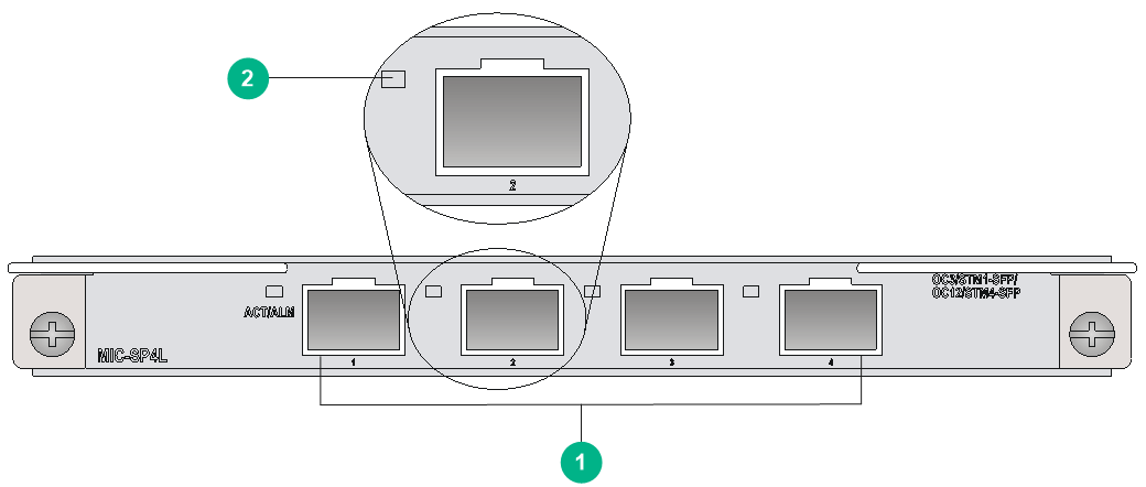
|
(1) OC-3c/STM-1c POS/ATM fiber ports (4 in total) or OC-12c/STM-4c POS/ATM fiber port (port 1) |
(2) Port LED. For the LED description, see Table2-334. |
LEDs
Table2-334 WAN port LED description
|
LED |
Status |
Description |
|
WAN port LED (ACT/ALM) |
Flashing green |
The port is up and is receiving or sending data correctly. |
|
Steady green |
The port is up and no services are running on the port. |
|
|
Steady red |
An alarm has occurred. |
|
|
Off |
The port is down. |
Ports
Table2-335 Port specifications
|
Card model |
Description |
Connector type |
Port quantity |
Port transmission speed |
|
MIC-SP4L |
4-port OC-3c/STM-1c POS/ATM or 1-port OC-12c/STM-4c POS/ATM optical interface card (SFP, LC) |
LC |
4 |
155 Mbps (OC-3/STM-1) |
|
1 |
622 Mbps (OC-12/STM-4) |
Technical specifications
Table2-336 Technical specifications
|
Item |
Description |
|
Dimensions (H × W × D) |
18 × 171 × 157 mm (0.71 × 6.73 × 6.18 in) |
|
Weight |
0.30 kg (0.66 lb) |
|
Maximum power consumption |
13.5 W |
|
Minimum power consumption |
9.6 W |
|
Operating temperature |
0°C to 45°C (32°F to 113°F) |
MIC-SP8L
View
Figure2-75 MIC-SP8L view
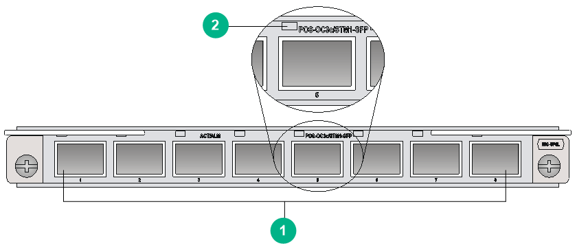
|
(1) OC-3c/STM-1c POS fiber ports (8 in total) |
(2) Port LED. For the LED description, see Table2-337. |
LEDs
Table2-337 WAN port LED description
|
LED |
Status |
Description |
|
WAN port LED (ACT/ALM) |
Flashing green |
The port is up and is receiving or sending data correctly. |
|
Steady green |
The port is up and no services are running on the port. |
|
|
Steady red |
An alarm has occurred. |
|
|
Off |
The port is down. |
Ports
Table2-338 Port specifications
|
Card model |
Description |
Connector type |
Port quantity |
Port transmission speed |
|
MIC-SP8L |
8-port OC-3c/STM-1c POS optical interface card (SFP, LC) |
LC |
8 |
155 Mbps (OC-3/STM-1) |
Technical specifications
Table2-339 Technical specifications
|
Item |
Description |
|
Dimensions (H × W × D) |
18 × 171 × 157 mm (0.71 × 6.73 × 6.18 in) |
|
Weight |
0.30 kg (0.66 lb) |
|
Maximum power consumption |
16.3 W |
|
Minimum power consumption |
14 W |
|
Operating temperature |
0°C to 45°C (32°F to 113°F) |
MIC-TCP8L
View
Figure2-76 MIC-TCP8L view
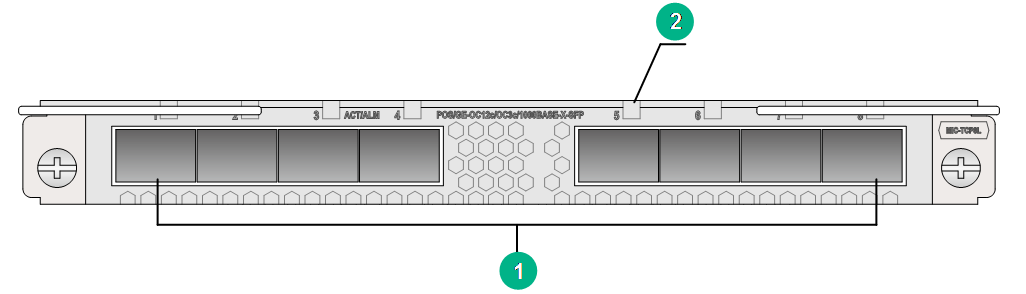
|
(1) OC-3c/OC-12c POS/GE fiber ports (8 in total) |
(2) Port LED. For the LED description, see Table2-340. |
LEDs
Table2-340 WAN port LED description
|
LED |
Status |
Description |
|
WAN port LED (ACT/ALM) |
Flashing green |
The port is up and is receiving or sending data correctly. |
|
Steady green |
The port is up and no services are running on the port. |
|
|
Steady red |
An alarm has occurred. |
|
|
Off |
The port is down. |
Ports
Table2-341 Port specifications
|
Card model |
Description |
Connector type |
Port quantity |
Port transmission speed |
|
MIC-TCP8L |
8-port OC-3c/OC-12c POS/GE optical interface card (SFP, LC) |
LC |
8 |
100 Mbps |
|
155 Mbps (OC-3/STM-1) |
||||
|
622 Mbps (OC-12/STM-4) |
||||
|
1000 Mbps |
Technical specifications
Table2-342 Technical specifications
|
Item |
Description |
|
Dimensions (H × W × D) |
18 × 171 × 157 mm (0.71 × 6.73 × 6.18 in) |
|
Weight |
0.40 kg (0.88 lb) |
|
Maximum power consumption |
30 W |
|
Minimum power consumption |
28 W |
|
Operating temperature |
0°C to 45°C (32°F to 113°F) |
MIC-XP10LF
View
Figure2-77 MIC-XP10LF view
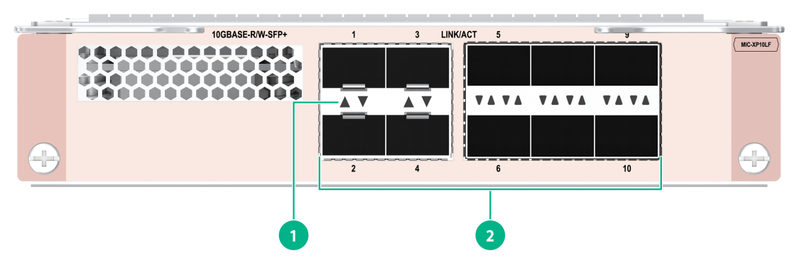
|
(1) Port LED. For the LED description, see Table2-343. |
(2) 25GBASE-R-SFP28 fiber ports (ports 1 to 4) or 10GBASE-R-SFP+ fiber ports |
LEDs
Table2-343 Port LED description
|
LED |
Status |
Description |
|
Port LED |
Flashing |
The port is receiving or sending data. |
|
Steady on |
A link is present on the port. |
|
|
Off |
No link is present on the port. |
|
|
NOTE: You can identify the speed of a port by observing the color of its LED. Green indicates a speed of 25 Gbps, and yellow indicates a speed of 10 Gbps or 1000 Mbps. |
Ports
Table2-344 Port specifications
|
Card model |
Description |
Connector type |
Port quantity |
Port transmission speed |
|
MIC-XP10LF |
10-port 10GBASE-R flexible Ethernet optical interface card (SFP+,LC) |
LC |
10 |
100 Mbps |
|
1000 Mbps |
||||
|
10 Gbps |
||||
|
4 |
25 Gbps |
Technical specifications
Table2-345 Technical specifications
|
Item |
Description |
|
Dimensions (H × W × D) |
36 × 171 × 157 mm (1.42 × 6.73 × 6.18 in) |
|
Weight |
0.61 kg (1.34 lb) |
|
Maximum power consumption |
37 W |
|
Minimum power consumption |
30 W |
|
Operating temperature |
0°C to 45°C (32°F to 113°F) |
MIC-XP10L-LAN
View
Figure2-78 MIC-XP10L-LAN view
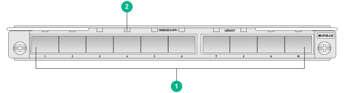
|
(1) 10GBASE-R-SFP+ fiber ports or 1000BASE-X-SFP fiber ports (10 in total) |
(2) SFP+ port LED. For the LED description, see Table2-346. |
LEDs
Table2-346 SFP+ port LED description
|
LED |
Status |
Description |
|
SFP+ port LED |
Flashing |
The port is sending or receiving data. |
|
Steady on |
A link is present on the port. |
|
|
Off |
No link is present on the port. |
|
|
NOTE: You can identify the speed of an SFP+ port by observing the color of its LED. Green indicates a speed of 10 Gbps, and yellow indicates a speed of 1000 Mbps. |
Ports
Table2-347 Port specifications
|
Card model |
Description |
Connector type |
Port quantity |
Port transmission speed |
|
MIC-XP10L-LAN |
10-port 10GBASE-R Ethernet optical interface card (SFP+, LC)-LAN |
LC |
10 |
10 Gbps |
|
1000 Mbps |
Technical specifications
Table2-348 Technical specifications
|
Item |
Description |
|
Dimensions (H × W × D) |
18 × 171 × 157 mm (0.71 × 6.73 × 6.18 in) |
|
Weight |
0.46 kg (1.01 lb) |
|
Maximum power consumption |
20 W |
|
Minimum power consumption |
12 W |
|
Operating temperature |
0°C to 45°C (32°F to 113°F) |
MIC-XP20L/MIC-XP20LA
View
Figure2-79 MIC-XP20L view
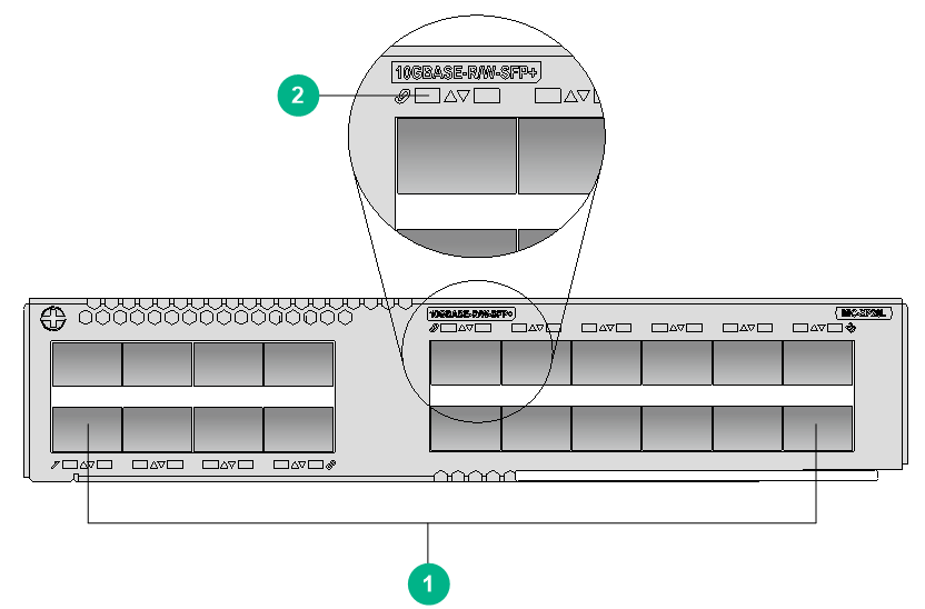
|
(1) 10GBASE-R/W-SFP+ fiber ports (20 in total) (10GE SFP+ modules supported) |
(2) SFP+ port LED. For the LED description, see Table2-349. |
The views of MIC-XP20L and MIC-XP20LA are similar. This figure uses the MIC-XP20L as an example.
LEDs
Table2-349 SFP+ port LED description
|
LED |
Status |
Description |
|
SFP+ port LED |
Flashing |
The port is sending or receiving data. |
|
Steady on |
A link is present on the port. |
|
|
Off |
No link is present on the port. |
|
|
NOTE: You can identify the speed of an SFP+ port by observing the color of its LED. Green indicates a speed of 10 Gbps, and yellow indicates a speed of 1000 Mbps. |
Ports
Table2-350 Port specifications
|
Card model |
Description |
Connector type |
Port quantity |
Port transmission speed |
|
MIC-XP20L |
20-port 10GBASE-R/W Ethernet optical interface card (SFP+, LC) |
LC |
20 |
100 Mbps |
|
1000 Mbps |
||||
|
10 Gbps |
||||
|
MIC-XP20LA |
20-port 10GBASE-R/W Ethernet optical interface card A (SFP+, LC) |
LC |
20 |
100 Mbps |
|
1000 Mbps |
||||
|
10 Gbps |
Technical specifications
Table2-351 Technical specifications
|
Item |
Description |
|
Dimensions (H × W × D) |
38 × 179 × 149 mm (1.50 × 7.05 × 5.87 in) |
|
Weight |
0.95 kg (2.09 lb) |
|
Maximum power consumption |
53 W |
|
Minimum power consumption |
38.3 W |
|
Operating temperature |
0°C to 45°C (32°F to 113°F) |
MIC-XP2L
View
Figure2-80 MIC-XP2L view
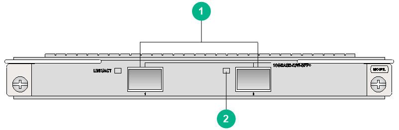
|
(1) 10GBASE-R/W-SFP+ fiber ports (2 in total) |
(2) SFP+ port LED. For the LED description, see Table2-352. |
LEDs
Table2-352 SFP+ port LED description
|
LED |
Status |
Description |
|
SFP+ port LED |
Flashing |
The port is sending or receiving data. |
|
Steady on |
A link is present on the port. |
|
|
Off |
No link is present on the port. |
|
|
NOTE: You can identify the speed of an SFP+ port by observing the color of its LED. Green indicates a speed of 10 Gbps, and yellow indicates a speed of 1000 Mbps. |
Ports
Table2-353 Port specifications
|
Card model |
Description |
Connector type |
Port quantity |
Port transmission speed |
|
MIC-XP2L |
2-port 10GBASE-R Ethernet optical interface card (SFP+, LC) |
LC |
2 |
100 Mbps |
|
1000 Mbps |
||||
|
10 Gbps |
Technical specifications
Table2-354 Technical specifications
|
Item |
Description |
|
Dimensions (H × W × D) |
18 × 171 × 157 mm (0.71 × 6.73 × 6.18 in) |
|
Weight |
0.29 kg (0.64 lb) |
|
Maximum power consumption |
13 W |
|
Minimum power consumption |
10 W |
|
Operating temperature |
0°C to 45°C (32°F to 113°F) |
MIC-XP2L-LAN
View
Figure2-81 MIC-XP2L-LAN view
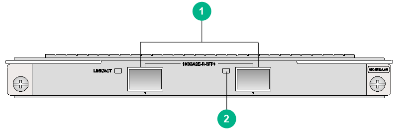
|
(1) 10GBASE-R-SFP+ fiber ports (2 in total) |
(2) SFP+ port LED. For the LED description, see Table2-355. |
LEDs
Table2-355 SFP+ port LED description
|
LED |
Status |
Description |
|
SFP+ port LED |
Flashing |
The port is sending or receiving data. |
|
Steady on |
A link is present on the port. |
|
|
Off |
No link is present on the port. |
|
|
NOTE: You can identify the speed of an SFP+ port by observing the color of its LED. Green indicates a speed of 10 Gbps, and yellow indicates a speed of 1000 Mbps. |
Ports
Table2-356 Port specifications
|
Card model |
Description |
Connector type |
Port quantity |
Port transmission speed |
|
MIC-XP2L-LAN |
2-port 10GBASE-R Ethernet optical interface card (SFP+, LC)-LAN |
LC |
2 |
100 Mbps |
|
1000 Mbps |
||||
|
10 Gbps |
Technical specifications
Table2-357 Technical specifications
|
Item |
Description |
|
Dimensions (H × W × D) |
18 × 171 × 157 mm (0.71 × 6.73 × 6.18 in) |
|
Weight |
0.28 kg (0.62 lb) |
|
Maximum power consumption |
9 W |
|
Minimum power consumption |
6 W |
|
Operating temperature |
0°C to 45°C (32°F to 113°F) |
MIC-XP4L1
View
Figure2-82 MIC-XP4L1 view
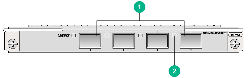
|
(1) 10GBASE-R/W-SFP+ fiber ports (4 in total) |
(2) SFP+ port LED. For the LED description, see Table2-358. |
LEDs
Table2-358 SFP+ port LED description
|
LED |
Status |
Description |
|
SFP+ port LED |
Flashing |
The port is sending or receiving data. |
|
Steady on |
A link is present on the port. |
|
|
Off |
No link is present on the port. |
|
|
NOTE: You can identify the speed of an SFP+ port by observing the color of its LED. Green indicates a speed of 10 Gbps, and yellow indicates a speed of 1000 Mbps. |
Ports
Table2-359 Port specifications
|
Card model |
Description |
Connector type |
Port quantity |
Port transmission speed |
|
MIC-XP4L1 |
4-port 10GBASE-R/W Ethernet optical interface card 1 (SFP+, LC) |
LC |
4 |
100 Mbps |
|
1000 Mbps |
||||
|
10 Gbps |
Technical specifications
Table2-360 MIC-XP4L1
|
Item |
Description |
|
Dimensions (H × W × D) |
18 × 171 × 157 mm (0.71 × 6.73 × 6.18 in) |
|
Weight |
0.30 kg (0.66 lb) |
|
Maximum power consumption |
13 W |
|
Minimum power consumption |
11 W |
|
Operating temperature |
0°C to 45°C (32°F to 113°F) |
MIC-XP5L
View
Figure2-83 MIC-XP5L view
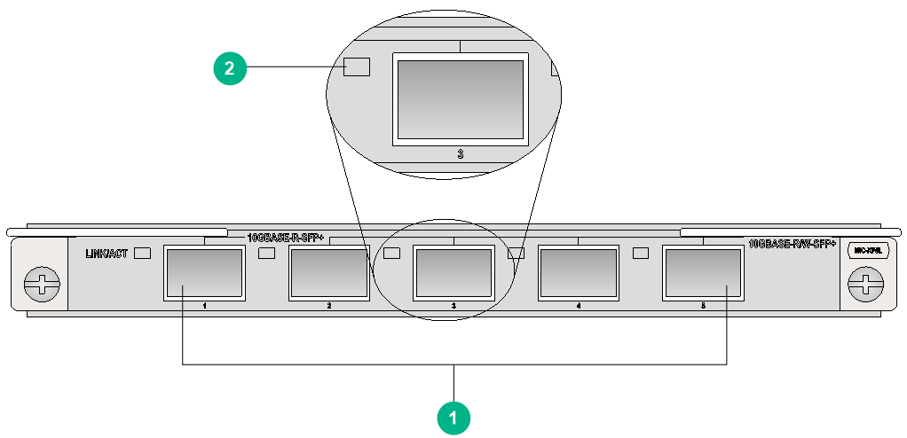
|
(1) 10GBASE-R/W-SFP+ fiber ports (5 in total) |
(2) SFP+ port LED. For the LED description, see Table2-361. |
LEDs
Table2-361 SFP+ port LED description
|
LED |
Status |
Description |
|
SFP+ port LED |
Flashing |
The port is sending or receiving data. |
|
Steady on |
A link is present on the port. |
|
|
Off |
No link is present on the port. |
|
|
NOTE: You can identify the speed of an SFP+ port by observing the color of its LED. Green indicates a speed of 10 Gbps, and yellow indicates a speed of 1000 Mbps. |
Ports
Table2-362 Port specifications
|
Card model |
Description |
Connector type |
Port quantity |
Port transmission speed |
|
MIC-XP5L |
5-port 10GBASE-R/W Ethernet optical interface card (SFP+, LC) |
LC |
5 |
100 Mbps |
|
1000 Mbps |
||||
|
10 Gbps |
Technical specifications
Table2-363 Technical specifications
|
Item |
Description |
|
Dimensions (H × W × D) |
18 × 171 × 157 mm (0.71 × 6.73 × 6.18 in) |
|
Weight |
0.30 kg (0.66 lb) |
|
Maximum power consumption |
14.2 W |
|
Minimum power consumption |
10.4 W |
|
Operating temperature |
0°C to 45°C (32°F to 113°F) |
MIC-XP5L1/MIC-XP5L2
View
Figure2-84 MIC-XP5L1 view
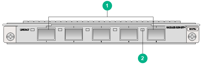
|
(1) 10GBASE-R/W-SFP+ fiber ports (5 in total) |
(2) SFP+ port LED. For the LED description, see Table2-364. |
The views of the MIC-XP5L1 and MIC-XP5L2 are similar. This figure uses the MIC-XP5L1 as an example.
LEDs
Table2-364 SFP+ port LED description
|
LED |
Status |
Description |
|
SFP+ port LED |
Flashing |
The port is sending or receiving data. |
|
Steady on |
A link is present on the port. |
|
|
Off |
No link is present on the port. |
|
|
NOTE: You can identify the speed of an SFP+ port by observing the color of its LED. Green indicates a speed of 10 Gbps, and yellow indicates a speed of 1000 Mbps. |
Ports
Table2-365 Port specifications
|
Card model |
Description |
Connector type |
Port quantity |
Port transmission speed |
|
MIC-XP5L1 |
5-port 10GBASE-R/W Ethernet optical interface card (SFP+, LC) |
LC |
5 |
100 Mbps |
|
1000 Mbps |
||||
|
10 Gbps |
||||
|
MIC-XP5L2 |
5-port 10GBASE-R Ethernet optical interface card (SFP+, LC) |
LC |
5 |
100 Mbps |
|
1000 Mbps |
||||
|
10 Gbps |
Technical specifications
Table2-366 Technical specifications
|
Item |
Description |
|
Dimensions (H × W × D) |
18 × 171 × 157 mm (0.71 × 6.73 × 6.18 in) |
|
Weight |
0.35 kg (0.77 lb) |
|
Maximum power consumption |
· MIC-XP5L1: 13 W · MIC-XP5L2: 6.4 W |
|
Minimum power consumption |
· MIC-XP5L1: 11 W · MIC-XP5L2: 2.3 W |
|
Operating temperature |
0°C to 45°C (32°F to 113°F) |
MIC-XP8L
View
Figure2-85 MIC-XP8L view
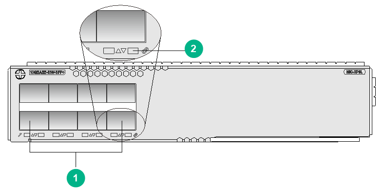
|
(1) 10GBASE-R/W-SFP+ fiber ports (8 in total) |
(2) SFP+ port LED. For the LED description, see Table2-367. |
LEDs
Table2-367 SFP+ port LED description
|
LED |
Status |
Description |
|
SFP+ port LED |
Flashing |
The port is sending or receiving data. |
|
Steady on |
A link is present on the port. |
|
|
Off |
No link is present on the port. |
|
|
NOTE: You can identify the speed of an SFP+ port by observing the color of its LED. Green indicates a speed of 10 Gbps, and yellow indicates a speed of 1000 Mbps. |
Ports
Table2-368 Port specifications
|
Card model |
Description |
Connector type |
Port quantity |
Port transmission speed |
|
MIC-XP8L |
8-port 10GBASE-R/W Ethernet optical interface card (SFP+, LC) |
LC |
8 |
10 Gbps |
Technical specifications
Table2-369 Technical specifications
|
Item |
Description |
|
Dimensions (H × W × D) |
38 × 179 × 149 mm (1.50 × 7.05 × 5.87 in) |
|
Weight |
0.70 kg (1.54 lb) |
|
Maximum power consumption |
22 W |
|
Minimum power consumption |
16 W |
|
Operating temperature |
0°C to 45°C (32°F to 113°F) |
NIC subcards
|
|
IMPORTANT: · To use a NIC interface card, you must install it on a CMPE, SPE, or CSPEX base card. You cannot install it directly on the router. · For the compatibility between NIC interface cards and CMPE, SPE, or CSPEX base cards, see the compatibility information for the base cards. · Some NIC subcards support changing the speed. For more information, see H3C CR16000-F Routers Configuration Guides. |
NIC-CC1L
View
Figure2-86 NIC-CC1L view
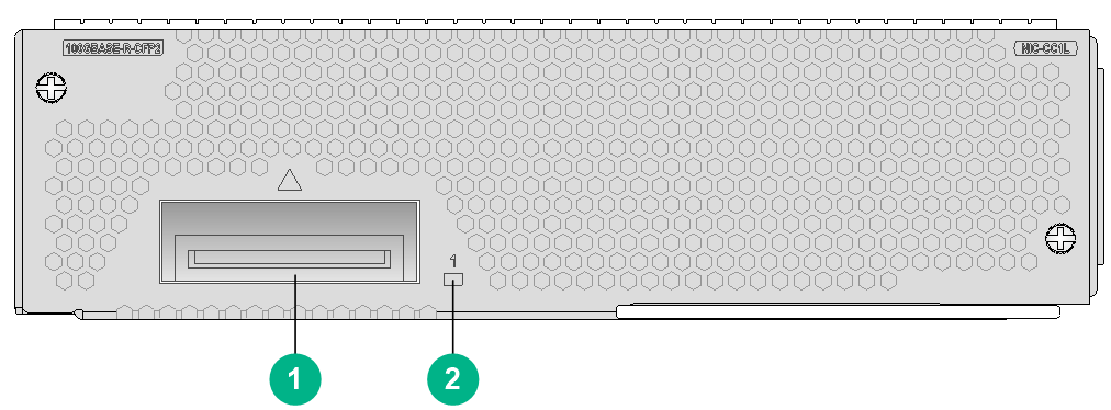
|
(1) 100GBASE-R-CFP2 fiber port (1 in total) |
(2) CFP2 port LED. For the LED description, see Table2-370. |
LEDs
Table2-370 CFP2 port LED description
|
LED |
Status |
Description |
|
CFP2 port LED |
Flashing |
The CFP2 port is sending or receiving data at 100 Gbps. |
|
Steady on |
A 100 Gbps link is present on the CFP2 port. |
|
|
Off |
No link is present on the CFP2 port. |
Ports
Table2-371 Port specifications
|
Card model |
Description |
Connector type |
Port quantity |
Port transmission speed |
|
NIC-CC1L |
1-port 100G Ethernet optical interface card |
LC |
1 |
100 Gbps |
Technical specifications
Table2-372 Technical specifications
|
Item |
Description |
|
Dimensions (H × W × D) |
47.5 × 179 × 118 mm (1.87 × 7.05 × 4.65 in) |
|
Weight |
0.60 kg (1.32 lb) |
|
Maximum power consumption |
9.7 W |
|
Minimum power consumption |
9.6 W |
|
Operating temperature |
0°C to 45°C (32°F to 113°F) |
NIC-CC2L
View
Figure2-87 NIC-CC2L view
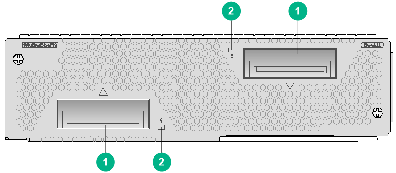
|
(1) 100GBASE-R-CFP2 fiber ports (2 in total) |
(2) CFP2 port LED. For the LED description, see Table2-373. |
LEDs
Table2-373 CFP2 port LED description
|
LED |
Status |
Description |
|
CFP2 port LED |
Flashing |
The CFP2 port is sending or receiving data at 100 Gbps. |
|
Steady on |
A 100 Gbps link is present on the CFP2 port. |
|
|
Off |
No link is present on the CFP2 port. |
Ports
Table2-374 Port specifications
|
Card model |
Description |
Connector type |
Port quantity |
Port transmission speed |
|
NIC-CC2L |
2-port 100G Ethernet optical interface card |
LC |
2 |
100 Gbps |
Technical specifications
Table2-375 Technical specifications
|
Item |
Description |
|
Dimensions (H × W × D) |
47.5 × 179 × 118 mm (1.87 × 7.05 × 4.65 in) |
|
Weight |
0.85 kg (1.87 lb) |
|
Maximum power consumption |
21 W |
|
Minimum power consumption |
19.2 W |
|
Operating temperature |
0°C to 45°C (32°F to 113°F) |
NIC-CQ1L
View
Figure2-88 NIC-CQ1L view
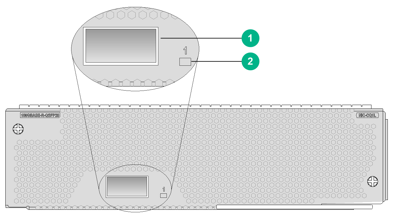
|
(1) 100GBASE-R-QSFP28 fiber port (1 in total) |
(2) QSFP28 port LED. For the LED description, see Table2-376. |
LEDs
Table2-376 QSFP28 port LED description
|
LED |
Status |
Description |
|
QSFP28 port LED |
Flashing |
The QSFP28 port is sending or receiving data at 100 Gbps. |
|
Steady on |
A 100 Gbps link is present on the QSFP28 port. |
|
|
Off |
No link is present on the QSFP28 port. |
Ports
Table2-377 Port specifications
|
Card model |
Description |
Connector type |
Port quantity |
Port transmission speed |
|
NIC-CQ1L |
1-port 100G Ethernet optical interface card |
LC |
1 |
100 Gbps |
Technical specifications
Table2-378 Technical specifications
|
Item |
Description |
|
Dimensions (H × W × D) |
47.5 × 179 × 118 mm (1.87 × 7.05 × 4.65 in) |
|
Weight |
0.35 kg (0.77 lb) |
|
Maximum power consumption |
13 W |
|
Minimum power consumption |
8 W |
|
Operating temperature |
0°C to 45°C (32°F to 113°F) |
NIC-CQ2L/NIC-CQ2LA/NIC-CQ2LA-G
View
Figure2-89 NIC-CQ2L view
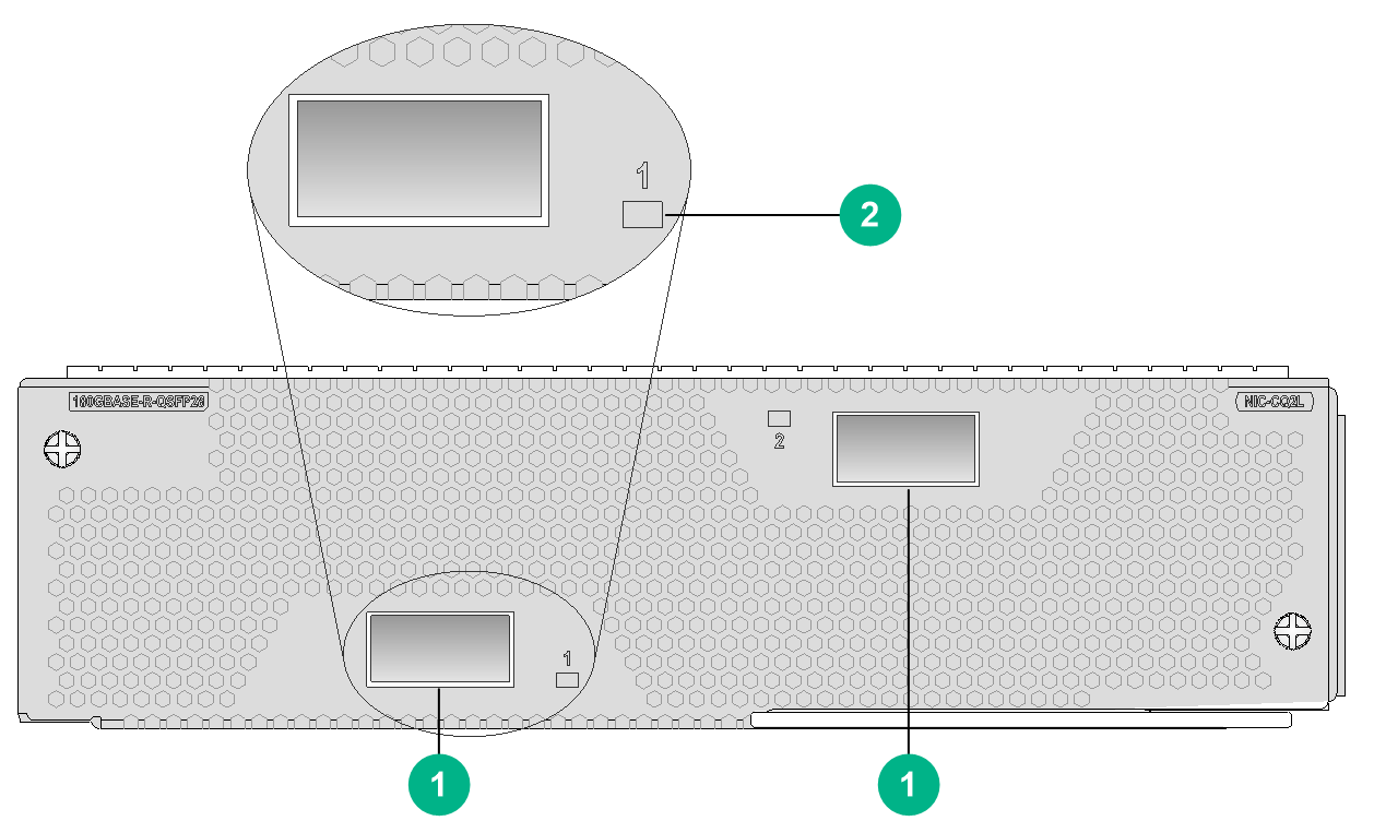
|
(1) 100GBASE-R-QSFP28 fiber ports (2 in total) |
(2) QSFP28 port LED. For the LED description, see Table2-379. |
The views of NIC-CQ2L, NIC-CQ2LA, and NIC-CQ2LA-G are similar. This figure uses the NIC-CQ2L as an example.
LEDs
Table2-379 QSFP28 port LED description
|
LED |
Status |
Description |
|
QSFP28 port LED |
Flashing |
The QSFP28 port is sending or receiving data at 100 Gbps. |
|
Steady on |
A 100 Gbps link is present on the QSFP28 port. |
|
|
Off |
No link is present on the QSFP28 port. |
Ports
Table2-380 Port specifications
|
Card model |
Description |
Connector type |
Port quantity |
Port transmission speed |
|
NIC-CQ2L |
2-port 100G Ethernet optical interface card |
LC |
2 |
100 Gbps |
|
NIC-CQ2LA |
2-port 100G Ethernet optical interface card A |
LC |
2 |
100 Gbps |
|
NIC-CQ2LA-G |
2-port 100G Ethernet optical interface card A |
LC |
2 |
100 Gbps |
Technical specifications
Table2-381 Technical specifications
|
Item |
Description |
|
Dimensions (H × W × D) |
47.5 × 179 × 118 mm (1.87 × 7.05 × 4.65 in) |
|
Weight |
· NIC-CQ2L: 0.35 kg (0.77 lb) · NIC-CQ2LA, NIC-CQ2LA-G: 0.75 kg (1.65 lb) |
|
Maximum power consumption |
26 W |
|
Minimum power consumption |
16 W |
|
Operating temperature |
0°C to 45°C (32°F to 113°F) |
NIC-GP20L
View
Figure2-90 NIC-GP20L view
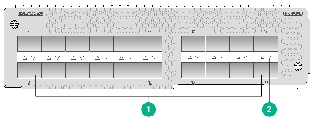
|
(1) 1000BASE-X-SFP fiber ports (20 in total) |
(2) SFP port LED. For the LED description, see Table2-382. |
LEDs
Table2-382 GE SFP port LED description
|
LED |
Status |
Description |
|
GE SFP port LED (LINK/ACT) |
Flashing green |
The SFP port is sending or receiving data. |
|
Green |
A link is present on the SFP port. |
|
|
Off |
No link is present on the SFP port. |
Ports
Table2-383 Port specifications
|
Card model |
Description |
Connector type |
Port quantity |
Port transmission speed |
|
NIC-GP20L |
20-port 1000BASE-X Ethernet optical interface card |
LC |
20 |
100 Mbps |
|
1000 Mbps |
Technical specifications
Table2-384 Technical specifications
|
Item |
Description |
|
Dimensions (H × W × D) |
47.5 × 179 × 118 mm (1.87 × 7.05 × 4.65 in) |
|
Weight |
0.65 kg (1.43 lb) |
|
Maximum power consumption |
13.8 W |
|
Minimum power consumption |
12 W |
|
Operating temperature |
0°C to 45°C (32°F to 113°F) |
NIC-GP24L
View
Figure2-91 NIC-GP24L view
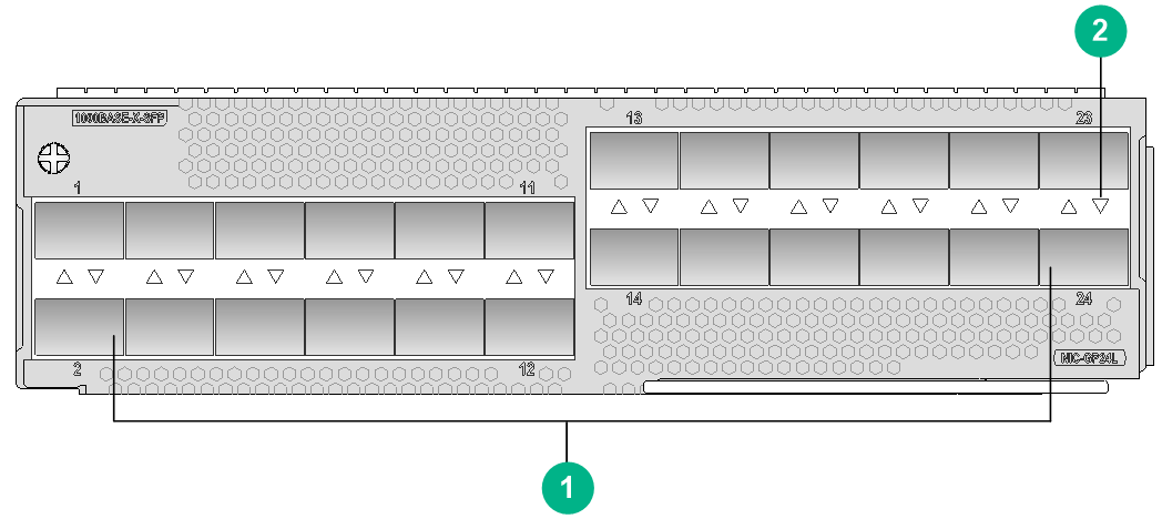
|
(1) 1000BASE-X-SFP fiber ports (24 in total) |
(2) SFP port LED. For the LED description, see Table2-385. |
LEDs
Table2-385 GE SFP port LED description
|
LED |
Status |
Description |
|
GE SFP port LED (LINK/ACT) |
Flashing green |
The SFP port is sending or receiving data. |
|
Green |
A link is present on the SFP port. |
|
|
Off |
No link is present on the SFP port. |
Ports
Table2-386 Port specifications
|
Card model |
Description |
Connector type |
Port quantity |
Port transmission speed |
|
NIC-GP24L |
24-port 1000BASE-X Ethernet optical interface card |
LC |
24 |
100 Mbps |
|
1000 Mbps |
Technical specifications
Table2-387 Technical specifications
|
Item |
Description |
|
Dimensions (H × W × D) |
47.5 × 179 × 118 mm (1.87 × 7.05 × 4.65 in) |
|
Weight |
0.50 kg (1.10 lb) |
|
Maximum power consumption |
28 W |
|
Minimum power consumption |
20 W |
|
Operating temperature |
0°C to 45°C (32°F to 113°F) |
NIC-GP24L1/NIC-GP24L1A/NIC-GP24L1A-G
View
Figure2-92 NIC-GP24L1 view
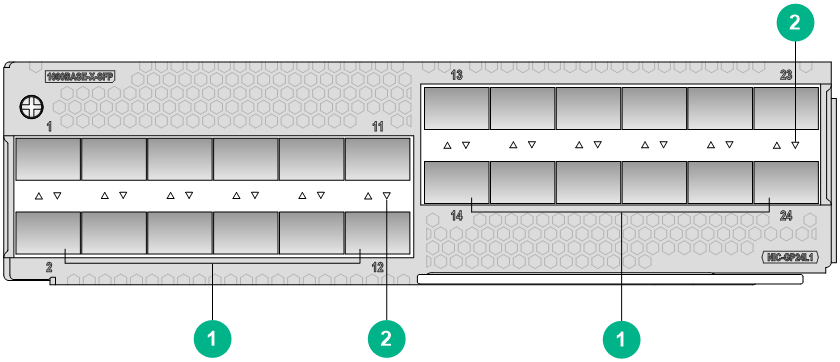
|
(1) 1000BASE-X-SFP fiber ports (24 in total) |
(2) SFP port LED. For the LED description, see Table2-388. |
The views of the NIC-GP24L1, NIC-GP24L1A, and NIC-GP24L1A-G are similar. This figure uses the NIC-GP24L1 as an example.
LEDs
Table2-388 GE SFP port LED description
|
LED |
Status |
Description |
|
GE SFP port LED (LINK/ACT) |
Flashing green |
The SFP port is sending or receiving data. |
|
Green |
A link is present on the SFP port. |
|
|
Off |
No link is present on the SFP port. |
Ports
Table2-389 Port specifications
|
Card model |
Description |
Connector type |
Port quantity |
Port transmission speed |
|
NIC-GP24L1 |
24-port 1000BASE-X Ethernet optical interface card |
LC |
24 |
100 Mbps |
|
1000 Mbps |
||||
|
NIC-GP24L1A |
24-port 1000BASE-X Ethernet optical interface card A |
LC |
24 |
1000 Mbps |
|
NIC-GP24L1A-G |
24-port 1000BASE-X Ethernet optical interface card A |
LC |
24 |
1000 Mbps |
Technical specifications
Table2-390 Technical specifications
|
Item |
Description |
|
Dimensions (H × W × D) |
47.5 × 179 × 118 mm (1.87 × 7.05 × 4.65 in) |
|
Weight |
1.00 kg (2.20 lb) |
|
Maximum power consumption |
47 W |
|
Minimum power consumption |
41 W |
|
Operating temperature |
0°C to 45°C (32°F to 113°F) |
NIC-GT20L
View
Figure2-93 NIC-GT20L view
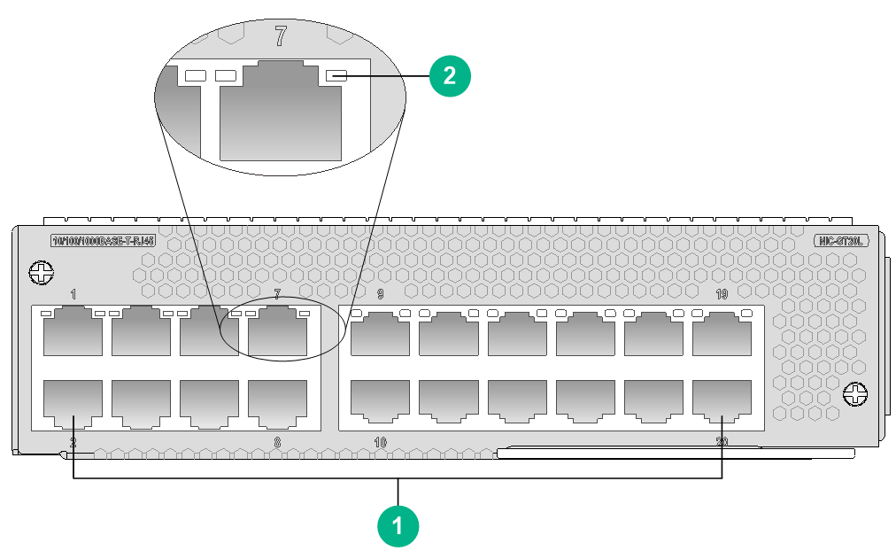
|
(1) 10/100/1000BASE-T copper ports (20 in total) |
(2) RJ-45 Ethernet port LED. For the LED description, see Table2-391. |
LEDs
Table2-391 RJ-45 Ethernet port LED description
|
LED |
Status |
Description |
|
RJ-45 Ethernet port LED |
Flashing |
The port is sending or receiving data. |
|
Steady on |
A link is present on the port. |
|
|
Off |
No link is present on the port. |
Ports
Table2-392 Port specifications
|
Card model |
Description |
Connector type |
Port quantity |
Port transmission speed |
|
NIC-GT20L |
20-port 1000BASE-T Ethernet copper interface card |
RJ-45 |
20 |
10/100/1000 Mbps |
Technical specifications
Table2-393 Technical specifications
|
Item |
Description |
|
Dimensions (H × W × D) |
47.5 × 179 × 118 mm (1.87 × 7.05 × 4.65 in) |
|
Weight |
0.75 kg (1.65 lb) |
|
Maximum power consumption |
16.5 W |
|
Minimum power consumption |
14.6 W |
|
Operating temperature |
0°C to 45°C (32°F to 113°F) |
NIC-QP3L
View
Figure2-94 NIC-QP3L view
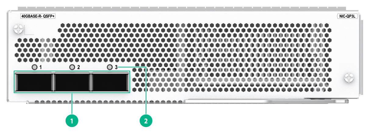
|
(1) 40GBASE-R-QSFP+ fiber ports (3 in total) |
(2) QSFP+ port LED. For the LED description, see Table2-394. |
LEDs
Table2-394 QSFP+ port LED description
|
LED |
Status |
Description |
|
QSFP+ port LED |
Flashing |
The port is sending or receiving data. |
|
Steady on |
A link is present on the port. |
|
|
Off |
No link is present on the port. |
Ports
Table2-395 Port specifications
|
Card model |
Description |
Connector type |
Port quantity |
Port transmission speed |
|
NIC-QP3L |
3-port 40G Ethernet optical interface card (QSFP+,LC) |
LC |
3 |
40 Gbps |
Technical specifications
Table2-396 Technical specifications
|
Item |
Description |
|
Dimensions (H × W × D) |
47.5 × 179 × 118 mm (1.87 × 7.05 × 4.65 in) |
|
Weight |
0.75 kg (1.65 lb) |
|
Maximum power consumption |
34 W |
|
Minimum power consumption |
33 W |
|
Operating temperature |
0°C to 45°C (32°F to 113°F) |
NIC-XP10L
View
Figure2-95 NIC-XP10L view
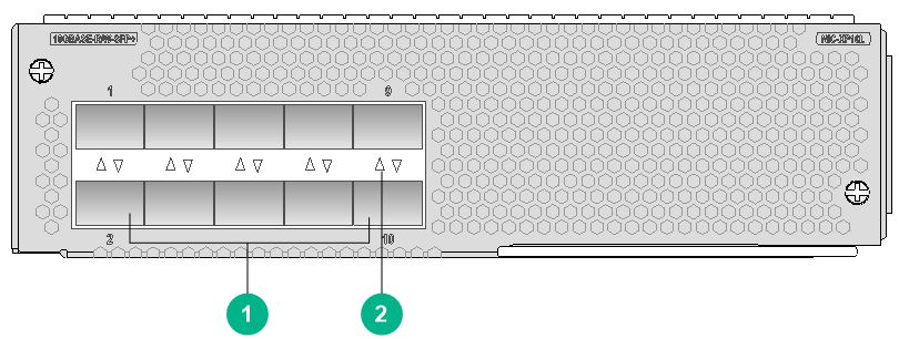
|
(1) 10GBASE-R/W-SFP+ fiber ports (10 in total) |
(2) SFP+ port LED. For the LED description, see Table2-397. |
LEDs
Table2-397 SFP+ port LED description
|
LED |
Status |
Description |
|
SFP+ port LED |
Flashing |
The port is sending or receiving data. |
|
Steady on |
A link is present on the port. |
|
|
Off |
No link is present on the port. |
|
|
NOTE: You can identify the speed of an SFP+ port by observing the color of its LED. Green indicates a speed of 10 Gbps, and yellow indicates a speed of 1000 Mbps. |
Ports
Table2-398 Port specifications
|
Card model |
Description |
Connector type |
Port quantity |
Port transmission speed |
|
NIC-XP10L |
10-port 10GBASE-R/W Ethernet optical interface card |
LC |
10 |
10 Gbps |
|
1000 Mbps |
Technical specifications
Table2-399 Technical specifications
|
Item |
Description |
|
Dimensions (H × W × D) |
47.5 × 179 × 118 mm (1.87 × 7.05 × 4.65 in) |
|
Weight |
0.65 kg (1.43 lb) |
|
Maximum power consumption |
27.4 W |
|
Minimum power consumption |
26.9 W |
|
Operating temperature |
0°C to 45°C (32°F to 113°F) |
NIC-XP20L
View
Figure2-96 NIC-XP20L view
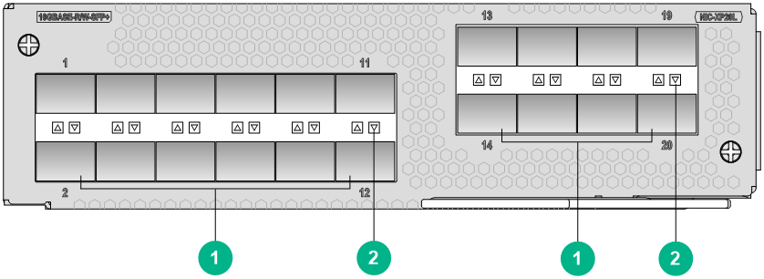
|
(1) 10GBASE-R/W-SFP+ fiber ports (20 in total) |
(2) SFP+ port LED. For the LED description, see Table2-400. |
LEDs
Table2-400 SFP+ port LED description
|
LED |
Status |
Description |
|
SFP+ port LED |
Flashing |
The port is sending or receiving data. |
|
Steady on |
A link is present on the port. |
|
|
Off |
No link is present on the port. |
|
|
NOTE: You can identify the speed of an SFP+ port by observing the color of its LED. Green indicates a speed of 10 Gbps, and yellow indicates a speed of 1000 Mbps. |
Ports
Table2-401 Port specifications
|
Card model |
Description |
Connector type |
Port quantity |
Port transmission speed |
|
NIC-XP20L |
20-port 10GBASE-R/W Ethernet optical interface card |
LC |
20 |
10 Gbps |
|
1000 Mbps |
Technical specifications
Table2-402 Technical specifications
|
Item |
Description |
|
Dimensions (H × W × D) |
47.5 × 179 × 118 mm (1.87 × 7.05 × 4.65 in) |
|
Weight |
0.90 kg (1.98 lb) |
|
Maximum power consumption |
58 W |
|
Minimum power consumption |
39 W |
|
Operating temperature |
0°C to 45°C (32°F to 113°F) |
NIC-XP20L1/NIC-XP20L1A/NIC-XP20L1A-G
View
Figure2-97 NIC-XP20L1 view

|
(1) 10GBASE-R/W-SFP+ fiber ports or 1000BASE-X-SFP fiber ports (20 in total) |
(2) SFP+ port/SFP port LED. For the SFP+ port LED description, see Table2-403. For the SFP port LED description, see Table2-404 |
The views of the NIC-XP20L1, NIC-XP20L1A, and NIC-XP20L1A-G are similar. This figure uses the NIC-XP20L1 as an example.
LEDs
Table2-403 SFP+ port LED description
|
LED |
Status |
Description |
|
SFP+ port LED |
Flashing |
The port is sending or receiving data. |
|
Steady on |
A link is present on the port. |
|
|
Off |
No link is present on the port. |
|
|
NOTE: You can identify the speed of an SFP+ port by observing the color of its LED. Green indicates a speed of 10 Gbps, and yellow indicates a speed of 1000 Mbps. |
Table2-404 GE SFP port LED description
|
LED |
Status |
Description |
|
GE SFP port LED (LINK/ACT) |
Flashing green |
The SFP port is sending or receiving data. |
|
Green |
A link is present on the SFP port. |
|
|
Off |
No link is present on the SFP port. |
Ports
Table2-405 Port specifications
|
Card model |
Description |
Connector type |
Port quantity |
Port transmission speed |
|
NIC-XP20L1 |
20-port 10GBASE-R/W Ethernet optical interface card |
LC |
20 |
10 Gbps |
|
1000 Mbps |
||||
|
NIC-XP20L1A |
20-port 10GBASE-R/W Ethernet optical interface card A |
LC |
20 |
10 Gbps |
|
1000 Mbps |
||||
|
NIC-XP20L1A-G |
20-port 10GBASE-R/W Ethernet optical interface card A |
LC |
20 |
10 Gbps |
|
1000 Mbps |
Technical specifications
Table2-406 Technical specifications
|
Item |
Description |
|
Dimensions (H × W × D) |
47.5 × 179 × 118 mm (1.87 × 7.05 × 4.65 in) |
|
Weight |
· NIC-XP20L1: 1.00 kg (2.20 lb) · NIC-XP20L1A, NIC-XP20L1A-G: 0.90 kg (1.98 lb) |
|
Maximum power consumption |
60 W |
|
Minimum power consumption |
50 W |
|
Operating temperature |
0°C to 45°C (32°F to 113°F) |
NIC-XP5L
View
Figure2-98 NIC-XP5L view
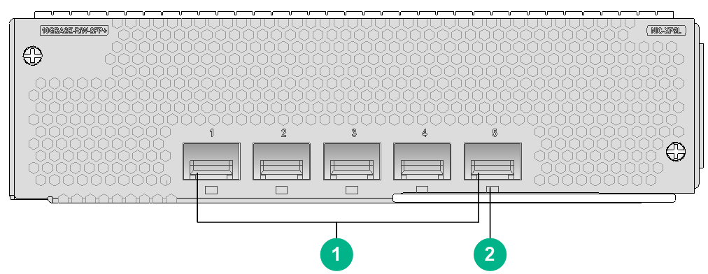
|
(1) 10GBASE-R/W-SFP+ fiber ports (5 in total) |
(2) SFP+ port LED. For the LED description, see Table2-407. |
LEDs
Table2-407 SFP+ port LED description
|
LED |
Status |
Description |
|
SFP+ port LED |
Flashing |
The port is sending or receiving data. |
|
Steady on |
A link is present on the port. |
|
|
Off |
No link is present on the port. |
|
|
NOTE: You can identify the speed of an SFP+ port by observing the color of its LED. Green indicates a speed of 10 Gbps, and yellow indicates a speed of 1000 Mbps. |
Ports
Table2-408 Port specifications
|
Card model |
Description |
Connector type |
Port quantity |
Port transmission speed |
|
NIC-XP5L |
5-port 10GBASE-R/W Ethernet optical interface card |
LC |
5 |
100 Mbps |
|
1000 Mbps |
||||
|
10 Gbps |
Technical specifications
Table2-409 Technical specifications
|
Item |
Description |
|
Dimensions (H × W × D) |
47.5 × 179 × 118 mm (1.87 × 7.05 × 4.65 in) |
|
Weight |
0.60 kg (1.32 lb) |
|
Maximum power consumption |
14.9 W |
|
Minimum power consumption |
11 W |
|
Operating temperature |
0°C to 45°C (32°F to 113°F) |
RX-NIC-CC1L
View
Figure2-99 RX-NIC-CC1L view
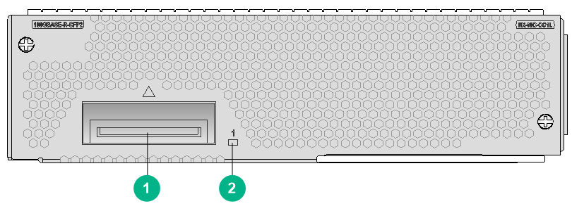
|
(1) 100GBASE-R-CFP2 fiber port (1 in total) |
(2) CFP2 port LED. For the LED description, see Table2-410. |
LEDs
Table2-410 CFP2 port LED description
|
LED |
Status |
Description |
|
CFP2 port LED |
Flashing |
The CFP2 port is sending or receiving data at 100 Gbps. |
|
Steady on |
A 100 Gbps link is present on the CFP2 port. |
|
|
Off |
No link is present on the CFP2 port. |
Ports
Table2-411 Port specifications
|
Card model |
Description |
Connector type |
Port quantity |
Port transmission speed |
|
RX-NIC-CC1L |
1-port 100G Ethernet optical interface card |
LC |
1 |
100 Gbps |
Technical specifications
Table2-412 Technical specifications
|
Item |
Description |
|
Dimensions (H × W × D) |
47.5 × 179 × 118 mm (1.87 × 7.05 × 4.65 in) |
|
Weight |
0.60 kg (1.32 lb) |
|
Maximum power consumption |
9.7 W |
|
Minimum power consumption |
9.6 W |
|
Operating temperature |
0°C to 45°C (32°F to 113°F) |
RX-NIC-CC2L
View
Figure2-100 RX-NIC-CC2L view
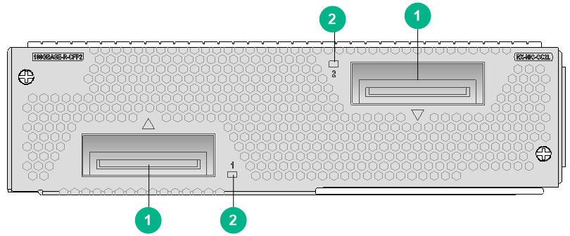
|
(1) 100GBASE-R-CFP2 fiber ports (2 in total) |
(2) CFP2 port LED. For the LED description, see Table2-413. |
LEDs
Table2-413 CFP2 port LED description
|
LED |
Status |
Description |
|
CFP2 port LED |
Flashing |
The CFP2 port is sending or receiving data at 100 Gbps. |
|
Steady on |
A 100 Gbps link is present on the CFP2 port. |
|
|
Off |
No link is present on the CFP2 port. |
Ports
Table2-414 Port specifications
|
Card model |
Description |
Connector type |
Port quantity |
Port transmission speed |
|
RX-NIC-CC2L |
2-port 100G Ethernet optical interface card |
LC |
2 |
100 Gbps |
Technical specifications
Table2-415 Technical specifications
|
Item |
Description |
|
Dimensions (H × W × D) |
47.5 × 179 × 118 mm (1.87 × 7.05 × 4.65 in) |
|
Weight |
0.85 kg (1.87 lb) |
|
Maximum power consumption |
21 W |
|
Minimum power consumption |
19.2 W |
|
Operating temperature |
0°C to 45°C (32°F to 113°F) |
RX-NIC-CQ1LF
View
Figure2-101 RX-NIC-CQ1LF view
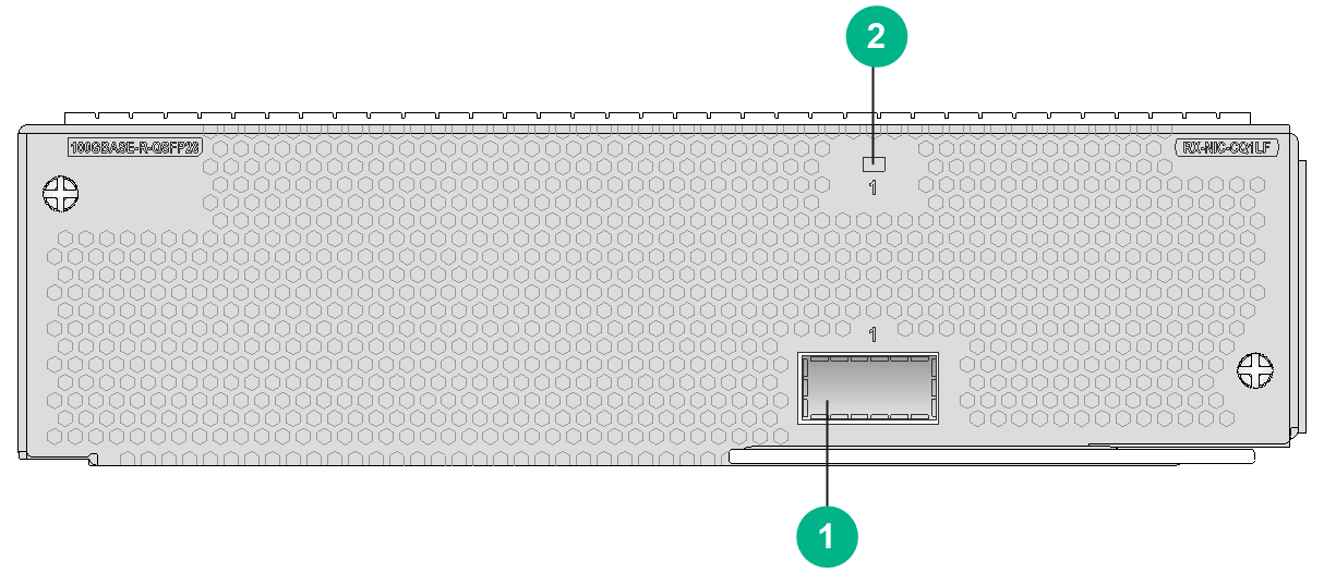
|
(1) 100GBASE-R-QSFP28 port (1 in total) |
(2) QSFP28 port LED. For the description, see Table2-416. |
LEDs
Table2-416 QSFP28 port LED description
|
LED |
Status |
Description |
|
QSFP28 port LED |
Flashing |
The QSFP28 port is sending or receiving data at 100 Gbps. |
|
Steady on |
A 100 Gbps link is present on the QSFP28 port. |
|
|
Off |
No link is present on the QSFP28 port. |
|
|
NOTE: You can identify the speed of a QSFP28 port by observing the color of its LED. Green indicates a speed of 100 Gbps, and yellow indicates a speed of 50 Gbps. |
Ports
Table2-417 Port specifications
|
Card model |
Description |
Connector type |
Port quantity |
Port transmission speed |
|
RX-NIC-CQ1LF |
1-port 100G flexible Ethernet optical interface card |
LC |
1 |
Standard Ethernet mode: 100 Gbps Flexible Ethernet mode: 100 Gbps |
Technical specifications
Table2-418 Technical specifications
|
Item |
Description |
|
Dimensions (H × W × D) |
47.5 × 179 × 118 mm (1.87 × 7.05 × 4.65 in) |
|
Weight |
0.85 kg (1.87 lb) |
|
Maximum power consumption |
53 W |
|
Minimum power consumption |
35 W |
|
Operating temperature |
0°C to 45°C (32°F to 113°F) |
RX-NIC-CQ2LF
View
Figure2-102 RX-NIC-CQ2LF view
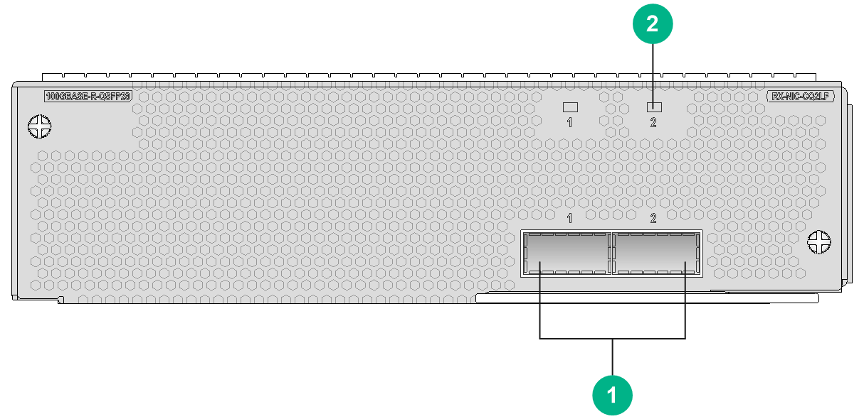
|
(1) 100GBASE-R-QSFP28 fiber ports (2 in total). |
(2) QSFP28 port LED. For the description, see Table2-419. |
LEDs
Table2-419 QSFP28 port LED description
|
LED |
Status |
Description |
|
QSFP28 port LED |
Flashing |
The QSFP28 port is sending or receiving data at 100 Gbps. |
|
Steady on |
A 100 Gbps link is present on the QSFP28 port. |
|
|
Off |
No link is present on the QSFP28 port. |
|
|
NOTE: You can identify the speed of a QSFP28 port by observing the color of its LED. Green indicates a speed of 100 Gbps, and yellow indicates a speed of 50 Gbps. |
Ports
Table2-420 Port specifications
|
Card model |
Description |
Connector type |
Port quantity |
Port transmission speed |
|
RX-NIC-CQ2LF |
2-port 100G flexible Ethernet optical interface card |
LC |
2 |
Standard Ethernet mode: 100 Gbps Flexible Ethernet mode: 100 Gbps |
Technical specifications
Table2-421 Technical specifications
|
Item |
Description |
|
Dimensions (H × W × D) |
47.5 × 179 × 118 mm (1.87 × 7.05 × 4.65 in) |
|
Weight |
1.00 kg (2.20 lb) |
|
Maximum power consumption |
61 W |
|
Minimum power consumption |
38 W |
|
Operating temperature |
0°C to 45°C (32°F to 113°F) |
RX-NIC-GP20L
View
Figure2-103 RX-NIC-GP20L view
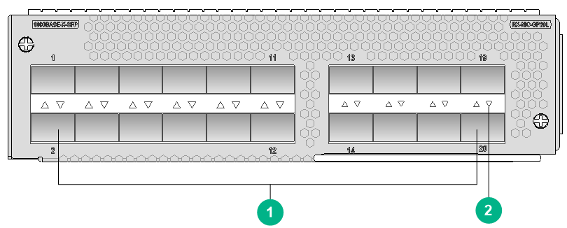
|
(1) 1000BASE-X-SFP fiber ports (20 in total) |
(2) SFP port LED. For the LED description, see Table2-422. |
LEDs
Table2-422 GE SFP port LED description
|
LED |
Status |
Description |
|
GE SFP port LED (LINK/ACT) |
Flashing green |
The SFP port is sending or receiving data. |
|
Green |
A link is present on the SFP port. |
|
|
Off |
No link is present on the SFP port. |
Ports
Table2-423 Port specifications
|
Card model |
Description |
Connector type |
Port quantity |
Port transmission speed |
|
RX-NIC-GP20L |
20-port 1000BASE-X Ethernet optical interface card |
LC |
20 |
100 Mbps |
|
1000 Mbps |
Technical specifications
Table2-424 Technical specifications
|
Item |
Description |
|
Dimensions (H × W × D) |
47.5 × 179 × 118 mm (1.87 × 7.05 × 4.65 in) |
|
Weight |
0.65 kg (1.43 lb) |
|
Maximum power consumption |
13.8 W |
|
Minimum power consumption |
12 W |
|
Operating temperature |
0°C to 45°C (32°F to 113°F) |
RX-NIC-LGQ2L
View
Figure2-104 RX-NIC-LGQ2L view
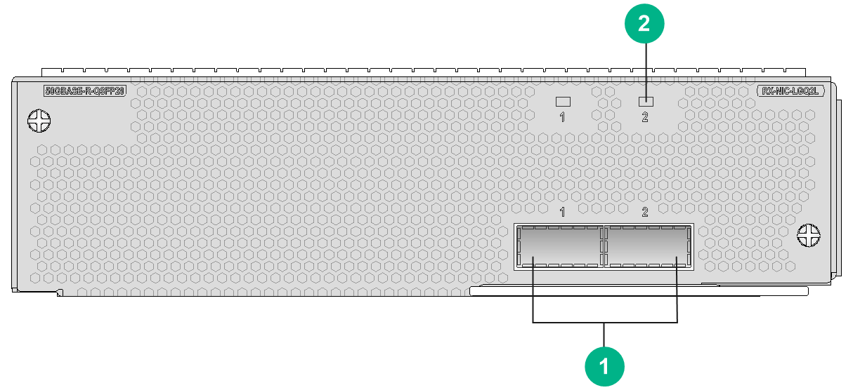
|
(1) 50GBASE-R-QSFP28 fiber ports (2 in total) |
(2) QSFP28 port LED. For the LED description, see Table2-425. |
LEDs
Table2-425 QSFP28 port LED description
|
LED |
Status |
Description |
|
QSFP28 port LEDs |
Flashing |
The QSFP28 port is sending or receiving data at 100 Gbps. |
|
Steady on |
A 100 Gbps link is present on the QSFP28 port. |
|
|
Off |
No link is present on the QSFP28 port. |
Ports
Table2-426 Port specifications
|
Card model |
Description |
Connector type |
Port quantity |
Port transmission speed |
|
RX-NIC-LGQ2L |
2-port 50G Ethernet optical interface card |
LC |
2 |
Standard Ethernet mode: 50 Gbps Flexible Ethernet mode: 50 Gbps |
Technical specifications
Table2-427 Technical specifications
|
Item |
Description |
|
Dimensions (H × W × D) |
47.5 × 179 × 118 mm (1.87 × 7.05 × 4.65 in) |
|
Weight |
0.85 kg (1.87 lb) |
|
Maximum power consumption |
61 W |
|
Minimum power consumption |
38 W |
|
Operating temperature |
0°C to 45°C (32°F to 113°F) |
RX-NIC-LGQ4L
View
Figure2-105 RX-NIC-LGQ4L view
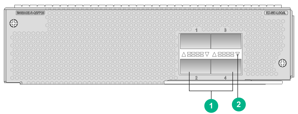
|
(1) 50GBASE-R-QSFP28 fiber ports (4 in total) |
(2) QSFP28 port LED. For the description, see Table2-428. |
LEDs
Table2-428 QSFP28 port LED description
|
LED |
Status |
Description |
|
QSFP28 port LED |
Flashing |
The QSFP28 port is sending or receiving data at 100 Gbps. |
|
Steady on |
A 100 Gbps link is present on the QSFP28 port. |
|
|
Off |
No link is present on the QSFP28 port. |
Ports
Table2-429 Port specifications
|
Card model |
Description |
Connector type |
Port quantity |
Port transmission speed |
|
RX-NIC-LGQ4L |
4-port 50G Ethernet optical interface card |
LC |
4 |
Standard Ethernet mode: 50 Gbps Flexible Ethernet mode: 50 Gbps |
Technical specifications
Table2-430 Technical specifications
|
Item |
Description |
|
Dimensions (H × W × D) |
47.5 × 179 × 118 mm (1.87 × 7.05 × 4.65 in) |
|
Weight |
0.90 kg (1.98 lb) |
|
Maximum power consumption |
92 W |
|
Minimum power consumption |
55 W |
|
Operating temperature |
0°C to 45°C (32°F to 113°F) |
RX-NIC-XP10L
View
Figure2-106 RX-NIC-XP10L view
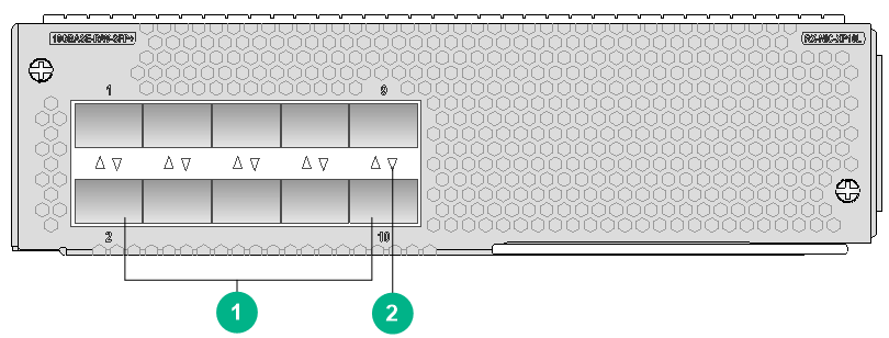
|
(1) 10GBASE-R/W-SFP+ fiber ports (10 in total) |
(2) SFP+ port LED. For the LED description, see Table2-431. |
LEDs
Table2-431 SFP+ port LED description
|
LED |
Status |
Description |
|
SFP+ port LED |
Flashing |
The port is sending or receiving data. |
|
Steady on |
A link is present on the port. |
|
|
Off |
No link is present on the port. |
|
|
NOTE: You can identify the speed of an SFP+ port by observing the color of its LED. Green indicates a speed of 10 Gbps, and yellow indicates a speed of 1000 Mbps. |
Ports
Table2-432 Port specifications
|
Card model |
Description |
Connector type |
Port quantity |
Port transmission speed |
|
RX-NIC-XP10L |
10-port 10GBASE-R/W Ethernet optical interface card |
LC |
10 |
100 Mbps |
|
1000 Mbps |
||||
|
10 Gbps |
Technical specifications
Table2-433 Technical specifications
|
Item |
Description |
|
Dimensions (H × W × D) |
47.5 × 179 × 118 mm (1.87 × 7.05 × 4.65 in) |
|
Weight |
0.65 kg (1.43 lb) |
|
Maximum power consumption |
27.4 W |
|
Minimum power consumption |
26.9 W |
|
Operating temperature |
0°C to 45°C (32°F to 113°F) |
RX-NIC-XP20L
View
Figure2-107 RX-NIC-XP20L view
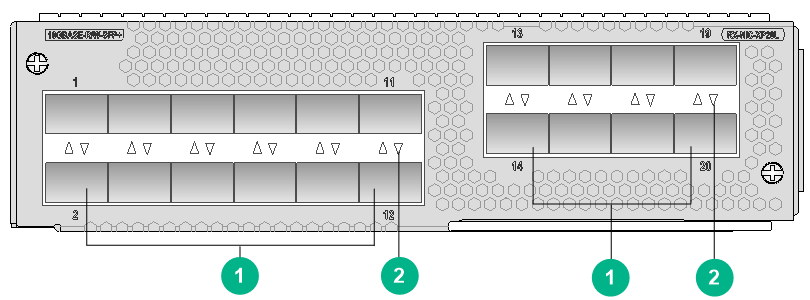
|
(1) 10GBASE-R/W-SFP+ fiber ports (20 in total) |
(2) SFP+ port LED. For the LED description, see Table2-434. |
LEDs
Table2-434 SFP+ port LED description
|
LED |
Status |
Description |
|
SFP+ port LED |
Flashing |
The port is sending or receiving data. |
|
Steady on |
A link is present on the port. |
|
|
Off |
No link is present on the port. |
|
|
NOTE: You can identify the speed of an SFP+ port by observing the color of its LED. Green indicates a speed of 10 Gbps, and yellow indicates a speed of 1000 Mbps. |
Ports
Table2-435 Port specifications
|
Card model |
Description |
Connector type |
Port quantity |
Port transmission speed |
|
RX-NIC-XP20L |
20-port 10GBASE-R/W Ethernet optical interface card |
LC |
20 |
100 Mbps |
|
1000 Mbps |
||||
|
10 Gbps |
Technical specifications
Table2-436 Technical specifications
|
Item |
Description |
|
Dimensions (H × W × D) |
47.5 × 179 × 118 mm (1.87 × 7.05 × 4.65 in) |
|
Weight |
1.00 kg (2.20 lb) |
|
Maximum power consumption |
58 W |
|
Minimum power consumption |
39 W |
|
Operating temperature |
0°C to 45°C (32°F to 113°F) |
RX-NIC-XP5L
View
Figure2-108 RX-NIC-XP5L view
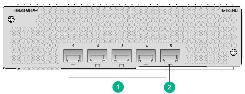
|
(1) 10GBASE-R/W-SFP+ fiber ports (5 in total) |
(2) SFP+ port LED. For the LED description, see Table2-437. |
LEDs
Table2-437 SFP+ port LED description
|
LED |
Status |
Description |
|
SFP+ port LED |
Flashing |
The port is sending or receiving data. |
|
Steady on |
A link is present on the port. |
|
|
Off |
No link is present on the port. |
|
|
NOTE: You can identify the speed of an SFP+ port by observing the color of its LED. Green indicates a speed of 10 Gbps, and yellow indicates a speed of 1000 Mbps. |
Ports
Table2-438 Port specifications
|
Card model |
Description |
Connector type |
Port quantity |
Port transmission speed |
|
RX-NIC-XP5L |
5-port 10GBASE-R/W Ethernet optical interface card |
LC |
5 |
100 Mbps |
|
1000 Mbps |
||||
|
10 Gbps |
Technical specifications
Table2-439 Technical specifications
|
Item |
Description |
|
Dimensions (H × W × D) |
47.5 × 179 × 118 mm (1.87 × 7.05 × 4.65 in) |
|
Weight |
0.60 kg (1.32 lb) |
|
Maximum power consumption |
14.9 W |
|
Minimum power consumption |
11 W |
|
Operating temperature |
0°C to 45°C (32°F to 113°F) |
RX-NIC-YGS4L
View
Figure2-109 RX-NIC-YGS4L view
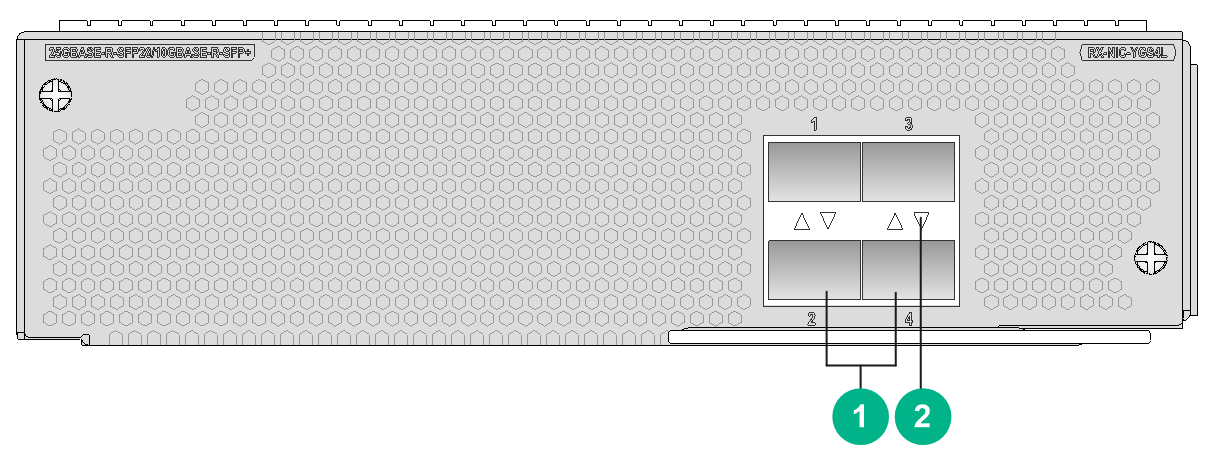
|
(1) 10GBASE-R-SFP+ ports or 25GBASE-R-SFP28 ports (4 in total) |
(2) SFP28 port LED. For the LED description, see Table2-440. |
LEDs
Table2-440 SFP28 port LED description
|
LED |
Status |
Description |
|
SFP28 port LED |
Flashing |
The port is sending or receiving data. |
|
Steady on |
A link is present on the port. |
|
|
Off |
No link is present on the port. |
|
|
NOTE: You can identify the speed of a QSFP28 port by observing the color of its LED. Green indicates a speed of 25 Gbps, and yellow indicates a speed of 10 Gbps. |
Ports
Table2-441 Port specifications
|
Card model |
Description |
Connector type |
Port quantity |
Port transmission speed |
|
RX-NIC-YGS4L |
4-port 25G Ethernet optical interface card |
LC |
4 |
10 Gbps |
|
25 Gbps |
Technical specifications
Table2-442 Technical specifications
|
Item |
Description |
|
Dimensions (H × W × D) |
47.5 × 179 × 118 mm (1.87 × 7.05 × 4.65 in) |
|
Weight |
0.80 kg (1.76 lb) |
|
Maximum power consumption |
38 W |
|
Minimum power consumption |
25 W |
|
Operating temperature |
0°C to 45°C (32°F to 113°F) |
PIC subcards
|
|
IMPORTANT: · To use a PIC interface card, you must install it on a CMPE, SPE, or CSPEX base card. You cannot install it directly on the router. · For the compatibility between PIC interface cards and CMPE, SPE, or CSPEX base cards, see the compatibility information for the base cards. |
PIC-GP10L
View
Figure2-110 PIC-GP10L view
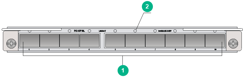
|
(1) 1000BASE-X-SFP Ethernet fiber ports (10 in total) |
(2) SFP port LED. For the LED description, see Table2-443. |
LEDs
Table2-443 GE SFP port LED description
|
LED |
Status |
Description |
|
GE SFP port LED (LINK/ACT) |
Flashing green |
The SFP port is sending or receiving data. |
|
Green |
A link is present on the SFP port. |
|
|
Off |
No link is present on the SFP port. |
Ports
Table2-444 Port specifications
|
Card model |
Description |
Connector type |
Port quantity |
Port transmission speed |
|
PIC-GP10L |
10-port 1000BASE-X optical interface card (SFP, LC) |
LC |
10 |
100 Mbps |
|
1000 Mbps |
Technical specifications
Table2-445 Technical specifications
|
Item |
Description |
|
Dimensions (H × W × D) |
18 × 171 × 157 mm (0.71 × 6.73 × 6.18 in) |
|
Weight |
0.45 kg (0.99 lb) |
|
Maximum power consumption |
21 W |
|
Minimum power consumption |
9.5 W |
|
Operating temperature |
0°C to 45°C (32°F to 113°F) |
PIC-PS2G4L
View
Figure2-111 PIC-PS2G4L view
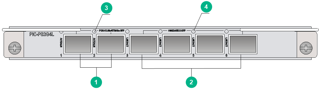
|
(1) OC48c/STM16c-SFP POS fiber ports (2 in total) |
(2) 1000BASE-X-SFP GE fiber ports (4 in total) |
|
(3) POS port LED. For the LED description, see Table2-446. |
(4) GE port LED. For the LED description, see Table2-447. |
LEDs
Table2-446 WAN port LED description
|
LED |
Status |
Description |
|
WAN port LED (ACT/ALM) |
Green |
The port is up and is receiving or sending data correctly. |
|
Red |
An alarm has occurred. |
|
|
Off |
The port is down. |
Table2-447 GE SFP port LED description
|
LED |
Status |
Description |
|
GE SFP port LED (LINK/ACT) |
Flashing green |
The SFP port is sending or receiving data. |
|
Green |
A link is present on the SFP port. |
|
|
Off |
No link is present on the SFP port. |
Ports
Table2-448 Port specifications
|
Card model |
Description |
Connector type |
Port quantity |
Port transmission speed |
|
PIC-PS2G4L |
2-port OC-48c/STM-16c POS optical interface (SFP, LC) + 4-port 1000BASE-X optical interface card (SFP, LC) |
LC |
2 |
2.5 Gbps (OC-48/STM-16) |
|
4 |
100 Mbps |
|||
|
1000 Mbps |
Technical specifications
Table2-449 Technical specifications
|
Item |
Description |
|
Dimensions (H × W × D) |
18 × 171 × 157 mm (0.71 × 6.73 × 6.18 in) |
|
Weight |
0.40 kg (0.88 lb) |
|
Maximum power consumption |
16 W |
|
Minimum power consumption |
9.3 W |
|
Operating temperature |
0°C to 45°C (32°F to 113°F) |
PIC-PSP4L
View
Figure2-112 PIC-PSP4L view
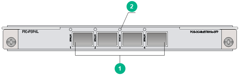
|
(1) OC48c/STM16c-SFP POS fiber ports (4 in total) |
(2) Port LED. For the LED description, see Table2-450. |
LEDs
Table2-450 WAN port LED description
|
LED |
Status |
Description |
|
WAN port LED (ACT/ALM) |
Green |
The port is up and is receiving or sending data correctly. |
|
Red |
An alarm has occurred. |
|
|
Off |
The port is down. |
Ports
Table2-451 Port specifications
|
Card model |
Description |
Connector type |
Port quantity |
Port transmission speed |
|
PIC-PSP4L |
4-port OC-48c/STM-16c POS optical interface card (SFP, LC) |
LC |
4 |
2.5 Gbps (OC-48/STM-16) |
Technical specifications
Table2-452 Technical specifications
|
Item |
Description |
|
Dimensions (H × W × D) |
18 × 171 × 157 mm (0.71 × 6.73 × 6.18 in) |
|
Weight |
0.40 kg (0.88 lb) |
|
Maximum power consumption |
18 W |
|
Minimum power consumption |
9.7 W |
|
Operating temperature |
0°C to 45°C (32 °F to 113 °F) |
PIC-PUP1L
View
Figure2-113 PIC-PUP1L view
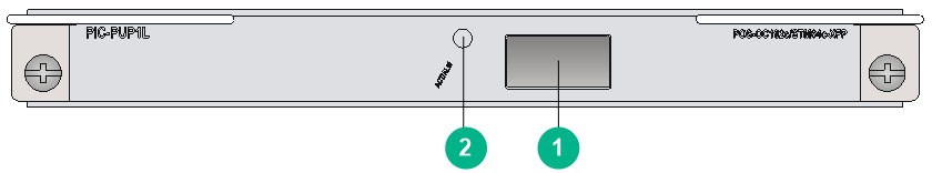
|
(1) OC192c/STM64c-XFP POS fiber port (1 in total) |
(2) Port LED. For the LED description, see Table2-453. |
LEDs
Table2-453 WAN port LED description
|
LED |
Status |
Description |
|
WAN port LED (ACT/ALM) |
Green |
The port is up and is receiving or sending data correctly. |
|
Red |
An alarm has occurred. |
|
|
Off |
The port is down. |
Ports
Table2-454 Port specifications
|
Card model |
Description |
Connector type |
Port quantity |
Port transmission speed |
|
PIC-PUP1L |
1-port OC-192c/STM-64c POS optical interface card (XFP, LC) |
LC |
1 |
10 Gbps (OC-192/STM-64) |
Technical specifications
Table2-455 PIC-PUP1L
|
Item |
Description |
|
Dimensions (H × W × D) |
18 × 171 × 157 mm (0.71 × 6.73 × 6.18 in) |
|
Weight |
0.50 kg (1.10 lb) |
|
Maximum power consumption |
19 W |
|
Minimum power consumption |
14.3 W |
|
Operating temperature |
0°C to 45°C (32°F to 113°F) |
PIC-TCP8L
View
Figure2-114 PIC-TCP8L view
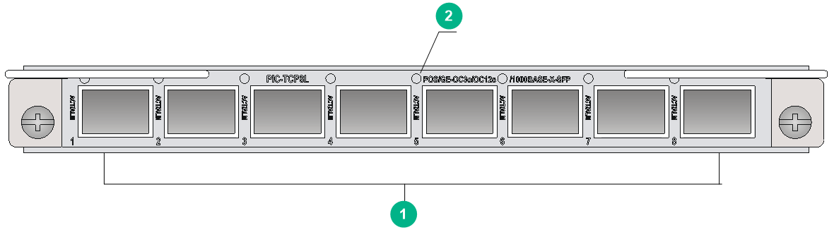
|
(1) OC3c/OC12c/1000BASE-X-SFP POS/GE fiber ports (8 in total) |
(2) Port LED. For the LED description, see Table2-456. |
LEDs
Table2-456 WAN port LED description
|
LED |
Status |
Description |
|
WAN port LED (ACT/ALM) |
Green |
The port is up and is receiving or sending data correctly. |
|
Red |
An alarm has occurred. |
|
|
Off |
The port is down. |
Ports
Table2-457 Port specifications
|
Card model |
Description |
Connector type |
Port quantity |
Port transmission speed |
|
PIC-TCP8L |
8-port OC-3c/OC-12c POS/GE optical interface card (SFP, LC) |
LC |
8 |
100 Mbps |
|
155 Mbps (OC-3/STM-1) |
||||
|
622 Mbps (OC-12/STM-4) |
||||
|
1000 Mbps |
Technical specifications
Table2-458 Technical specifications
|
Item |
Description |
|
Dimensions (H × W × D) |
18 × 171 × 157 mm (0.71 × 6.73 × 6.18 in) |
|
Weight |
0.40 kg (0.88 lb) |
|
Maximum power consumption |
17 W |
|
Minimum power consumption |
9.7 W |
|
Operating temperature |
0°C to 45°C (32°F to 113°F) |
PIC-XP1L
View
Figure2-115 PIC-XP1L view
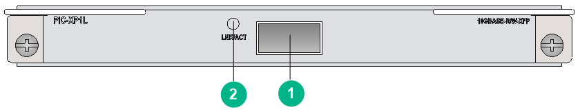
|
(1) 10GBASE-R/W-XFP Ethernet fiber port (1 in total) |
(2) XFP port LED. For the LED description, see Table2-459. |
LEDs
Table2-459 10GE XFP port LED description
|
LED |
Status |
Description |
|
10GE XFP port LED (LINK/ACT) |
Flashing green |
The XFP port is sending or receiving data. |
|
Green |
A link is present on the XFP port. |
|
|
Off |
No link is present on the XFP port. |
Ports
Table2-460 Port specifications
|
Card model |
Description |
Connector type |
Port quantity |
Port transmission speed |
|
PIC-XP1L |
1-port 10GBASE-R/W Ethernet optical interface card (XFP, LC) |
LC |
1 |
10 Gbps |
Technical specifications
Table2-461 Technical specifications
|
Item |
Description |
|
Dimensions (H × W × D) |
18 × 171 × 157 mm (0.71 × 6.73 × 6.18 in) |
|
Weight |
0.45 kg (0.99 lb) |
|
Maximum power consumption |
23.7 W |
|
Minimum power consumption |
12.5 W |
|
Operating temperature |
0°C to 45°C (32°F to 113°F) |
OAA modules
LSU1ADECEA0
View
Figure2-116 LSU1ADECEA0 view
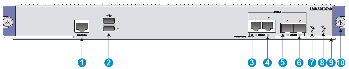
|
(1) Console port (CONSOLE) |
(2) USB port (reserved for future use) |
|
(3) Combo copper port (10/100/1000BASE-T) |
(4) Combo copper port LED (LINK/ACT) |
|
(5) Combo fiber port (1000BASE-X) |
(6) Combo fiber port LED (LINK/ACT) |
|
(7) Alarm LED (ALM) |
(8) System LED (RUN) |
|
(9) Ejector lever |
(10) Captive screw |
LEDs
Table2-462 LED description
|
LED |
Mark |
Status |
Description |
|
Alarm LED |
ALM |
Off |
The system is operating correctly. |
|
Steady red |
A critical fault has occurred to the system and the fault must be handled immediately. |
||
|
System LED |
RUN |
Off |
No power is input or the service module has failed. |
|
Steady green |
The system is running incorrectly. |
||
|
Slow flashing green (1 Hz) |
The system is operating correctly. |
||
|
Fast flashing green (8 Hz) |
The system is loading software or has not started. |
||
|
Combo interface LED |
LINK/ACT |
Off |
No link is present. |
|
Steady green |
A link is present. |
||
|
Flashing green |
The interface is sending or receiving data. |
Ports
Table2-463 Port specifications
|
Card model |
Description |
Connector type |
Port quantity |
Port transmission speed |
|
LSU1ADECEA0 |
Application delivery service module |
RJ-45 |
2 |
10/100/1000 Mbps |
|
LC |
2 |
1000 Mbps |
Technical specifications
Table2-464 Technical specifications
|
Item |
Description |
|
Dimensions (H × W × D) |
40 × 399 × 352 mm (1.57 × 15.71 × 13.86 in) |
|
Weight |
3.90 kg (8.60 lb) |
|
Maximum power consumption |
150 W |
|
Minimum power consumption |
109 W |
|
Operating temperature |
0°C to 45°C (32°F to 113°F) |
IM-ACG1000X-IV
View
Figure2-117 IM-ACG1000X-IV view
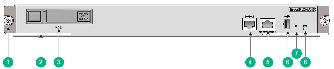
|
(1) Captive screw |
(2) Ejector lever |
|
(3) Drive slot |
(4) Console port (CONSOLE) |
|
(5) GE copper port (10/100/1000BASE-T) |
(6) USB port |
|
(7) Drive LED (HD) |
(8) System LED (SYS) |
LEDs
Table2-465 LED description
|
LED |
Mark |
Status |
Description |
|
Drive LED |
HD |
Fast flashing green |
Data is being read from or written to the drive. |
|
Steady green |
The drive is running correctly. |
||
|
Off |
The drive is absent. |
||
|
System LED |
SYS |
Off |
No power is input or the service module has failed. |
|
Slow flashing green |
The system is operating correctly. |
||
|
Fast flashing green |
The system is loading software. |
Ports
Table2-466 Port specifications
|
Card model |
Description |
Connector type |
Port quantity |
Port transmission speed |
|
IM-ACG1000X-IV |
Application control gateway module |
RJ45 |
1 |
10/100/1000 Mbps |
Technical specifications
Table2-467 Technical specifications
|
Item |
Description |
|
Dimensions (H × W × D) |
40 × 399 × 352 mm (1.57 × 15.71 × 13.86 in) |
|
Weight |
4.80 kg (10.60 lb) |
|
Maximum power consumption |
235 W |
|
Minimum power consumption |
175 W |
|
Operating temperature |
0°C to 45°C (32°F to 113°F) |
IM-IPSX-IV
View
Figure2-118 IM-IPSX-IV view
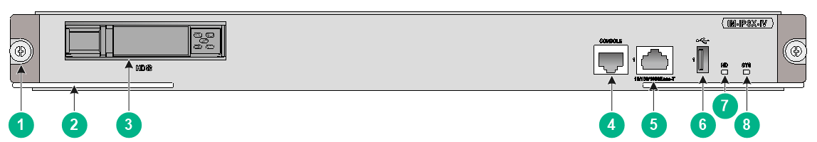
|
(1) Captive screw |
(2) Ejector lever |
|
(3) Drive slot |
(4) Console port (CONSOLE) |
|
(5) GE copper port (10/100/1000BASE-T) |
(6) USB port |
|
(7) Drive LED (HD) |
(8) System LED (SYS) |
LEDs
Figure2-119 LED description
|
LED |
Mark |
Status |
Description |
|
Drive LED |
HD |
Fast flashing green |
Data is being read from or written to the drive. |
|
Steady green |
The drive is running correctly. |
||
|
Off |
The drive is absent. |
||
|
System LED |
SYS |
Off |
No power is input or the service module has failed. |
|
Slow flashing green |
The system is operating correctly. |
||
|
Fast flashing green |
The system is loading software. |
Ports
Table2-468 Port specifications
|
Card model |
Description |
Connector type |
Port quantity |
Port transmission speed |
|
IM-IPSX-IV |
Intrusion prevention system module |
RJ45 |
1 |
10/100/1000 Mbps |
Technical specifications
Table2-469 Technical specifications
|
Item |
Description |
|
Dimensions (H × W × D) |
40 × 399 × 352 mm (1.57 × 15.71 × 13.86 in) |
|
Weight |
4.80 kg (10.58 lb) |
|
Maximum power consumption |
235 W |
|
Minimum power consumption |
175 W |
|
Operating temperature |
0°C to 45°C (32°F to 113°F) |
IM-NGFWX-IV
View
Figure2-120 IM-NGFWX-IV view
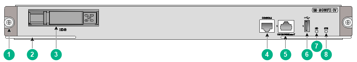
|
(1) Captive screw |
(2) Ejector lever |
|
(3) Drive slot |
(4) Console port (CONSOLE) |
|
(5) GE copper port (10/100/1000BASE-T) |
(6) USB port |
|
(7) Drive LED (HD) |
(8) System LED (SYS) |
LEDs
Table2-470 LED description
|
LED |
Mark |
Status |
Description |
|
Drive LED |
HD |
Fast flashing green |
Data is being read from or written to the drive. |
|
Steady green |
The drive is running correctly. |
||
|
Off |
The drive is absent. |
||
|
System LED |
SYS |
Off |
No power is input or the service module has failed. |
|
Slow flashing green |
The system is operating correctly. |
||
|
Fast flashing green |
The system is loading software. |
Ports
Table2-471 Port specifications
|
Card model |
Description |
Connector type |
Port quantity |
Port transmission speed |
|
IM-NGFWX-IV |
Firewall module |
RJ45 |
1 |
10/100/1000 Mbps |
Technical specifications
Table2-472 Technical specifications
|
Item |
Description |
|
Dimensions (H × W × D) |
40 × 399 × 352 mm (1.57 × 15.71 × 13.86 in) |
|
Weight |
4.80 kg (10.58 lb) |
|
Maximum power consumption |
235 W |
|
Minimum power consumption |
175 W |
|
Operating temperature |
0°C to 45°C (32°F to 113°F) |
LSU1FWCEA0
View
Figure2-121 LSU1FWCEA0 view
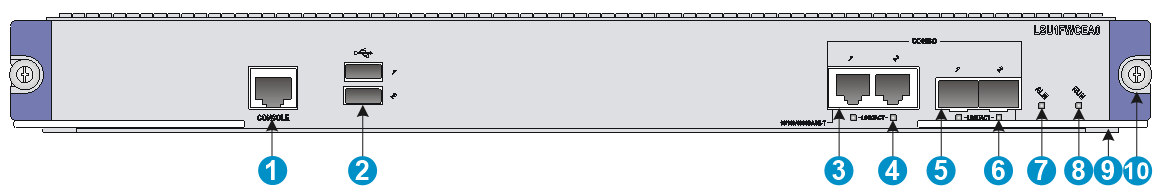
|
(1) Console port (CONSOLE) |
(2) USB port (reserved for future use) |
|
(3) Combo copper port (10/100/1000BASE-T) |
(4) Combo copper port LED (LINK/ACT) |
|
(5) Combo fiber port (1000BASE-X) |
(6) Combo fiber port LED (LINK/ACT) |
|
(7) Alarm LED (ALM) |
(8) System LED (RUN) |
|
(9) Ejector lever |
(10) Captive screw |
LEDs
Table2-473 LED description
|
LED |
Mark |
Status |
Description |
|
Alarm LED |
ALM |
Off |
The system is operating correctly. |
|
Steady red |
A critical fault has occurred to the system and the fault must be handled immediately. |
||
|
System LED |
RUN |
Off |
No power is input or the service module has failed. |
|
Steady green |
The system is running incorrectly. |
||
|
Slow flashing green (1 Hz) |
The system is operating correctly. |
||
|
Fast flashing green (8 Hz) |
The system is loading software or has not started. |
||
|
Combo interface LED |
LINK/ACT |
Off |
No link is present. |
|
Steady green |
A link is present. |
||
|
Flashing green |
The interface is sending or receiving data. |
Ports
Table2-474 Port specifications
|
Card model |
Description |
Connector type |
Port quantity |
Port transmission speed |
|
LSU1FWCEA0 |
Firewall module |
RJ45 |
2 |
10/100/1000 Mbps |
|
LC |
2 |
1000 Mbps |
Technical specifications
Table2-475 Technical specifications
|
Item |
Description |
|
Dimensions (H × W × D) |
40 × 399 × 352 mm (1.57 × 15.71 × 13.86 in) |
|
Weight |
3.90 kg (8.60 lb) |
|
Maximum power consumption |
150 W |
|
Minimum power consumption |
109 W |
|
Operating temperature |
0°C to 45°C (32°F to 113°F) |
LSU1IPSBEA0
View
Figure2-122 LSU1IPSBEA0 view
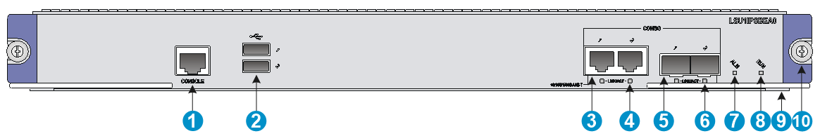
|
(1) Console port (CONSOLE) |
(2) USB port (Control power supply of the external PFC power fail safeguard module) |
|
(3) Combo copper port (10/100/1000BASE-T) |
(4) Combo copper port LED (LINK/ACT) |
|
(5) Combo fiber port (1000BASE-X) |
(6) Combo fiber port LED (LINK/ACT) |
|
(7) Alarm LED (ALM) |
(8) System LED (RUN) |
|
(9) Ejector lever |
(10) Captive screw |
LEDs
Table2-476 LED description
|
LED |
Mark |
Status |
Description |
|
Alarm LED |
ALM |
Off |
The system is operating correctly. |
|
Steady red |
A critical fault has occurred to the system and the fault must be handled immediately. |
||
|
System LED |
RUN |
Off |
No power is input or the service module has failed. |
|
Steady green |
The system is running incorrectly. |
||
|
Slow flashing green (1 Hz) |
The system is operating correctly. |
||
|
Fast flashing green (8 Hz) |
The system is loading software or has not started. |
||
|
Combo interface LED |
LINK/ACT |
Off |
No link is present. |
|
Steady green |
A link is present. |
||
|
Flashing green |
The interface is sending or receiving data. |
Ports
Table2-477 Port specifications
|
Card model |
Description |
Connector type |
Port quantity |
Port transmission speed |
|
LSU1IPSBEA0 |
Intrusion prevention system module |
RJ45 |
2 |
10/100/1000 Mbps |
|
LC |
2 |
1000 Mbps |
Technical specifications
Table2-478 Technical specifications
|
Item |
Description |
|
Dimensions (H × W × D) |
40 × 399 × 352 mm (1.57 × 15.71 × 13.86 in) |
|
Weight |
3.90 kg (8.60 lb) |
|
Maximum power consumption |
150 W |
|
Minimum power consumption |
109 W |
|
Operating temperature |
0°C to 45°C (32°F to 113°F) |
LSU3FWCEA0
View
Figure2-123 LSU3FWCEA0 view
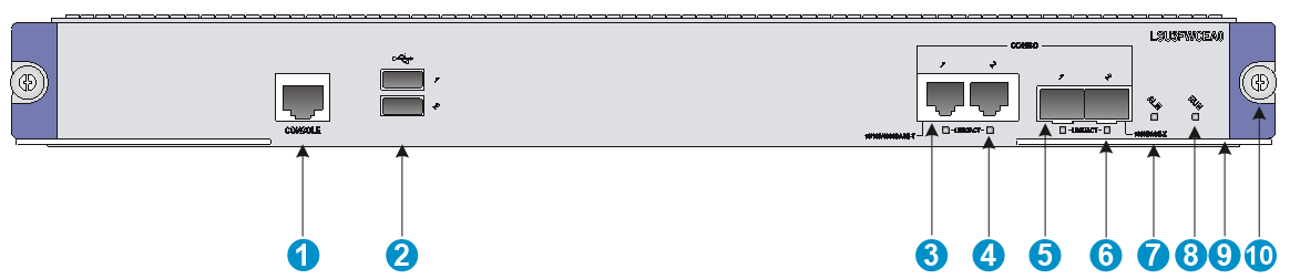
|
(1) Console port (CONSOLE) |
(2) USB port (reserved for future use) |
|
(3) Combo copper port (10/100/1000BASE-T) |
(4) Combo copper port LED (LINK/ACT) |
|
(5) Combo fiber port (1000BASE-X) |
(6) Combo fiber port LED (LINK/ACT) |
|
(7) Alarm LED (ALM) |
(8) System LED (RUN) |
|
(9) Ejector lever |
(10) Captive screw |
LEDs
Table2-479 LED description
|
LED |
Mark |
Status |
Description |
|
Alarm LED |
ALM |
Off |
The system is operating correctly. |
|
Steady red |
A critical fault has occurred to the system and the fault must be handled immediately. |
||
|
System LED |
RUN |
Off |
No power is input or the service module has failed. |
|
Steady green |
The system is running incorrectly. |
||
|
Slow flashing green (1 Hz) |
The system is operating correctly. |
||
|
Fast flashing green (8 Hz) |
The system is loading software or has not started. |
||
|
Combo interface LED |
LINK/ACT |
Off |
No link is present. |
|
Steady green |
A link is present. |
||
|
Flashing green |
The interface is sending or receiving data. |
Ports
Table2-480 Port specifications
|
Card model |
Description |
Connector type |
Port quantity |
Port transmission speed |
|
LSU3FWCEA0 |
Firewall module |
RJ-45 |
2 |
10/100/1000 Mbps |
|
LC |
2 |
1000 Mbps |
Technical specifications
Table2-481 Technical specifications
|
Item |
Description |
|
Dimensions (H × W × D) |
40 × 399 × 352 mm (1.57 × 15.71 × 13.86 in) |
|
Weight |
3.90 kg (8.60 lb) |
|
Maximum power consumption |
150 W |
|
Minimum power consumption |
109 W |
|
Operating temperature |
0°C to 45°C (32°F to 113°F) |
Configuration restrictions and guidelines
For adequate ventilation and cooling, install the IM-NGFWX-IV, IM-IPSX-IV, and IM-ACG1000X-IV cards in the following slots only when the other slots are not available.
· CR16010-F router—Slots 0, 8 and 9.
· CR16014-F router—Slots 0 and 13.
Compatibility information
Table2-482 Compatibility matrix between OAA cards and routers
|
Card model |
CR16006-F, CR16010-F, CR16014-F |
CR16010H-F (with five fabric modules), CR16018-F (with five fabric modules) |
CR16010H-F (with four fabric modules), CR16018-F (with four fabric modules) |
CR16010H-FA, CR16018-FA |
CR16003E-F, CR16005E-F, CR16010E-F |
|
IM-NGFWX-IV |
Supported |
Supported |
Not supported |
Not supported |
Supported |
|
LSU1FWCEA0 |
Supported |
Not supported |
Not supported |
Not supported |
Not supported |
|
LSU3FWCEA0 |
Supported |
Not supported |
Not supported |
Not supported |
Not supported |
|
IM-IPSX-IV |
Supported |
Supported |
Not supported |
Not supported |
Not supported |
|
LSU1IPSBEA0 |
Supported |
Not supported |
Not supported |
Not supported |
Not supported |
|
IM-ACG1000X-IV |
Supported |
Supported |
Not supported |
Not supported |
Not supported |
|
LSU1ADECEA0 |
Supported |
Not supported |
Not supported |
Not supported |
Not supported |
IM modules (Universal line processing unit)
IM-APA-I
View
Figure2-124 IM-APA-I view
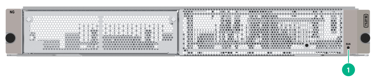
|
(1) Card status LED. For the LED description, see Table2-483. |
LED
Table2-483 Card status LED description
|
LED |
Status |
Description |
|
RUN (Green) |
Steady on |
The card is faulty. |
|
Off |
The card is faulty or is not in position. |
|
|
Flashing (about once per second) |
The card is operating correctly. |
|
|
Fast flashing |
The card is starting up. If the LED keeps fast flashing, card registration has failed. |
Ports
Table2-484 Port specifications
|
Card model |
Description |
|
IM-APA-I |
iBRAS application-aware line processing unit |
Technical specifications
Table2-485 Technical specifications
|
Item |
Description |
|
Dimensions (H × W × D) |
52.5 × 399 × 352 mm (2.07 × 15.71 × 13.86 in) |
|
Weight |
3.12 kg (6.88 lb) |
|
Maximum power consumption |
400 W |
|
Power consumption (with typical configuration) |
260 W |
|
Minimum power consumption |
248 W |
|
Operating temperature |
0°C to 45°C (32°F to 113°F) |
IM-MSUX (1 U)
View
Figure2-125 IM-MSUX (1 U) view
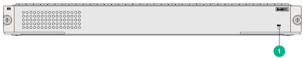
|
(1) Card status LED. For the LED description, see Table2-486. |
LED
Table2-486 Card status LED description
|
LED |
Status |
Description |
|
RUN (Green) |
Steady on |
The card is faulty. |
|
Off |
The card is faulty or is not in position. |
|
|
Flashing (about once per second) |
The card is operating correctly. |
|
|
Fast flashing |
The card is starting up. If the LED keeps fast flashing, card registration has failed. |
Ports
Table2-487 Port specifications
|
Card model |
Description |
|
IM-MSUX (1 U) |
Universal line processing unit |
Technical specifications
Table2-488 Technical specifications
|
Item |
Description |
|
Dimensions (H × W × D) |
40 × 399 × 352 mm (1.57 × 15.71 × 13.86 in) |
|
Weight |
4.95 kg (10.91 lb) |
|
Maximum power consumption |
186 W |
|
Power consumption (with typical configuration) |
175 W |
|
Minimum power consumption |
158.2 W |
|
Operating temperature |
0°C to 45°C (32°F to 113°F) |
IM-MSUX (1.2 U)
View
Figure2-126 IM-MSUX (1.2 U) view
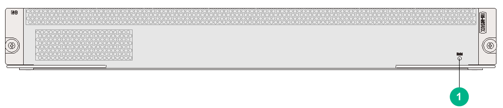
|
(1) Card status LED. For the LED description, see Table2-489. |
LEDs
Table2-489 Card status LED description
|
LED |
Status |
Description |
|
RUN (Green) |
Steady on |
The card is faulty. |
|
Off |
The card is faulty or is not in position. |
|
|
Flashing (about once per second) |
The card is operating correctly. |
|
|
Fast flashing |
The card is starting up. If the LED keeps fast flashing, card registration has failed. |
Ports
Table2-490 Port specifications
|
Card model |
Description |
|
IM-MSUX (1.2 U) |
Universal line processing unit |
Technical specifications
Table2-491 Technical specifications
|
Item |
Description |
|
Dimensions (H × W × D) |
52.5 × 399 × 352 mm (2.07 × 15.71 × 13.86 in) |
|
Weight |
4.85 kg (10.69 lb) |
|
Maximum power consumption |
186 W |
|
Power consumption (with typical configuration) |
175 W |
|
Minimum power consumption |
158.2 W |
|
Operating temperature |
0°C to 45°C (32°F to 113°F) |
IM-MSEX-B
|
|
NOTE: The IM-MSEX-B provides one subcard slot. You can use it without a subcard, or use it with an IM-SP-B for double CGN packet processing rate. |
View
Figure2-127 IM-MSEX-B view
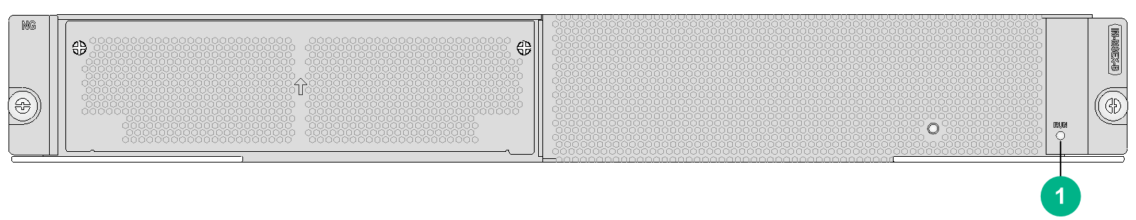
|
(1) Card status LED. For the LED description, see Table2-492. |
LEDs
Table2-492 Card status LED description
|
LED |
Status |
Description |
|
RUN (Green) |
Steady on |
The card is faulty. |
|
Off |
The card is faulty or is not in position. |
|
|
Flashing (about once per second) |
The card is operating correctly. |
|
|
Fast flashing |
The card is starting up. If the LED keeps fast flashing, card registration has failed. |
Ports
Table2-493 Port specifications
|
Card model |
Description |
|
IM-MSEX-B |
Service processing unit |
Technical specifications
Table2-494 Technical specifications
|
Item |
Description |
|
Dimensions (H × W × D) |
52.5 × 399 × 352 mm (2.07 × 15.71 × 13.86 in) |
|
Weight |
3.12 kg (6.88 lb) |
|
Maximum power consumption |
400 W |
|
Power consumption (with typical configuration) |
260 W |
|
Minimum power consumption |
248 W |
|
Operating temperature |
0°C to 45°C (32°F to 113°F) |
IM-SP-B
|
|
NOTE: The IM-SP-B must be installed on an IM-APA-I or IM-MSEX-B for use. It occupies one subcard slot and does not provide ports. |
View
Figure2-128 IM-SP-B view
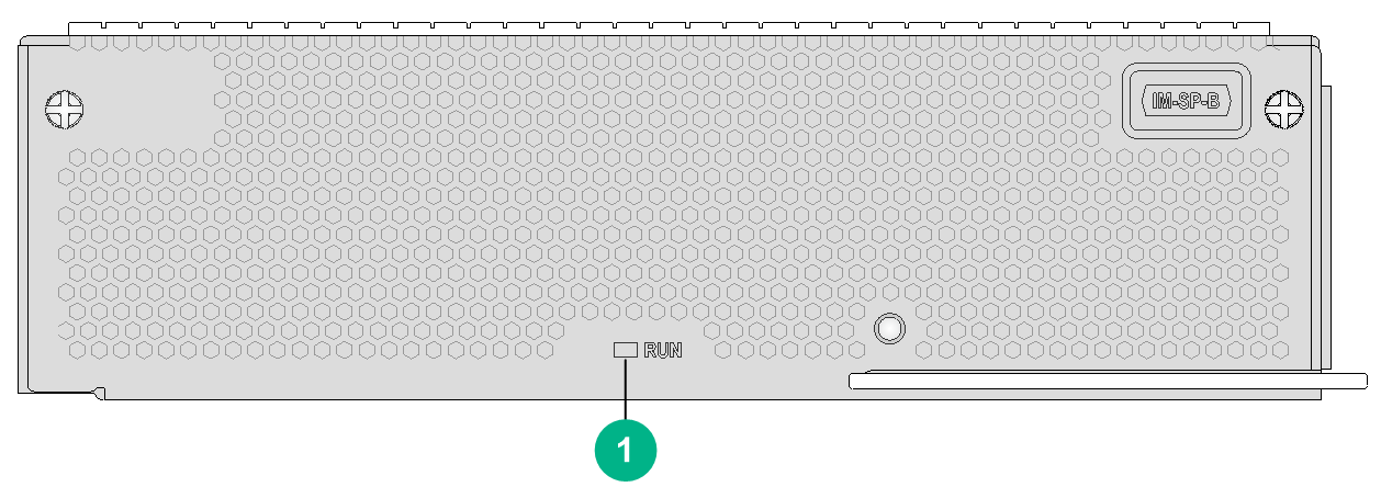
|
(1) Card status LED. For the LED description, see Table2-495. |
LEDs
Table2-495 Card status LED description
|
LED |
Status |
Description |
|
RUN (Green) |
Steady on |
The card is faulty. |
|
Off |
The card is faulty or is not in position. |
|
|
Flashing (about once per second) |
The card is operating correctly. |
|
|
Fast flashing |
The card is starting up. If the LED keeps fast flashing, card registration has failed. |
Ports
Table2-496 Port specifications
|
Card model |
Description |
|
IM-SP-B |
Universal expansion service processing module |
Technical specifications
Table2-497 Technical specifications
|
Item |
Description |
|
Dimensions (H × W × D) |
47.5 × 170 × 192 mm (1.87 × 6.69 × 7.56 in) |
|
Weight |
1.20 kg (2.65 lb) |
|
Maximum power consumption |
130 W |
|
Minimum power consumption |
95 W |
|
Operating temperature |
0°C to 45°C (32°F to 113°F) |
Configuration restrictions and guidelines
For adequate ventilation and cooling, install the IM-MSUX (1U) card in the following slots only when the other slots are not available:
· CR16010-F router—Slots 0, 8 and 9.
· CR16014-F router—Slots 0 and 13.
Compatibility information
Table2-498 Compatibility matrix between universal line processing units and routers
|
Card model |
CR16006-F, CR16010-F, CR16014-F |
CR16010H-F (with five fabric modules), CR16018-F (with five fabric modules) |
CR16010H-F (with four fabric modules), CR16018-F (with four fabric modules) |
CR16010H-FA, CR16018-FA |
CR16003E-F, CR16005E-F, CR16010E-F |
|
IM-APA-I |
Not supported |
Supported |
Supported |
Not supported |
Not supported |
|
IM-MSUX (1 U) |
Supported |
Supported |
Not supported |
Not supported |
Supported |
|
IM-MSUX (1.2 U) |
Not supported |
Supported |
Supported |
Not supported |
Not supported |
|
IM-MSEX-B |
Not supported |
Supported |
Supported |
Not supported |
Not supported |
IM modules (Security monitor line processing unit)
IM-SMUX
View
Figure2-129 IM-SMUX view
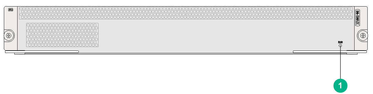
|
(1) Card status LED. For the LED description, see Table2-499. |
LEDs
Table2-499 Card status LED description
|
LED |
Status |
Description |
|
RUN (Green) |
Steady on |
The card is faulty. |
|
Off |
The card is faulty or is not in position. |
|
|
Flashing (about once per second) |
The card is operating correctly. |
|
|
Fast flashing |
The card is starting up. If the LED keeps fast flashing, card registration has failed. |
Ports
Table2-500 Port specifications
|
Card model |
Description |
|
IM-SMUX |
Security monitor line processing unit |
Technical specifications
Table2-501 Technical specifications
|
Item |
Description |
|
Dimensions (H × W × D) |
52.5 × 399 × 352 mm (2.07 × 15.71 × 13.86 in) |
|
Weight |
4.85 kg (10.69 lb) |
|
Maximum power consumption |
186 W |
|
Power consumption (with typical configuration) |
175 W |
|
Minimum power consumption |
159 W |
|
Operating temperature |
0°C to 45°C (32°F to 113°F) |
Compatibility information
Table2-502 Compatibility matrix between security monitor line processing units and routers
|
Card model |
CR16006-F, CR16010-F, CR16014-F |
CR16010H-F (with five fabric modules), CR16018-F (with five fabric modules) |
CR16010H-F (with four fabric modules), CR16018-F (with four fabric modules) |
CR16010H-FA, CR16018-FA |
CR16003E-F, CR16005E-F, CR16010E-F |
|
IM-SMUX |
Not supported |
Supported |
Supported |
Not supported |
Not supported |
IM modules (Network data encryption service processing unit)
IM-SFMX
|
|
NOTE: The IM-SFMX provides one subcard slot. When used without a subcard, it uses non-SM algorithms to encrypt and decrypt network data. When used with an MIC-SM, it uses SM algorithms to encrypt and decrypt network data. |
View
Figure2-130 IM-SFMX view
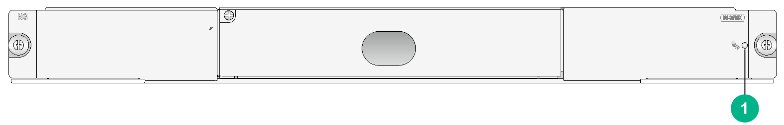
|
(1) Card status LED. For the LED description, see Table2-503. |
LEDs
Table2-503 Card status LED description
|
LED |
Status |
Description |
|
RUN (Green) |
Steady on |
The card is faulty. |
|
Off |
The card is faulty or is not in position. |
|
|
Flashing (about once per second) |
The card is operating correctly. |
|
|
Fast flashing |
The card is starting up. If the LED keeps fast flashing, card registration has failed. |
Ports
Table2-504 Port specifications
|
Card model |
Description |
|
IM-SFMX |
Network data encryption service processing unit |
Technical specifications
Table2-505 Technical specifications
|
Item |
Description |
|
Dimensions (H × W × D) |
40 × 399 × 355 mm (1.57 × 15.71 × 13.86 in) |
|
Weight |
4.05 kg (8.93 lb) |
|
Maximum power consumption |
165 W |
|
Power consumption (with typical configuration) |
113 W |
|
Minimum power consumption |
90 W |
|
Operating temperature |
0°C to 45°C (32°F to 113°F) |
MIC-SEC
|
|
NOTE: The MIC-SEC must be installed on a card for use. It occupies one subcard slot. For more information, see the compatibility information between CMPE cards, SPE cards, or CSPEX cards between subcards. |
View
Figure2-131 MIC-SEC view
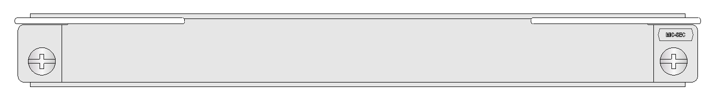
Ports
Table2-506 Port specifications
|
Card model |
Description |
Connector type |
Port quantity |
Port transmission speed |
|
MIC-SEC |
Network data encryption service processing interface card |
N/A |
N/A |
N/A |
Technical specifications
Table2-507 Technical specifications
|
Item |
Description |
|
Dimensions (H × W × D) |
18 × 171 × 157 mm (0.71 × 6.73 × 6.18 in) |
|
Weight |
0.40 kg (0.88 lb) |
|
Maximum power consumption |
31 W |
|
Minimum power consumption |
29 W |
|
Operating temperature |
0°C to 45°C (32°F to 113°F) |
MIC-SM
|
|
NOTE: · The MIC-SM is not hot swappable. · The MIC-SM must be installed on an IM-SFMX for use. It occupies one subcard slot. · The MIC-SM is provided with six USB keys for you to obtain user roles to manage the card. To obtain a user role, first insert a USB key into USB port AUTH. For more information about the encryption card configuration, see H3C CR16000-F Routers Configuration Guides. |
View
Figure2-132 MIC-SM view
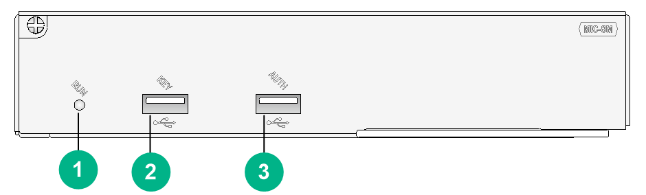
|
(1) Card status LED. For the LED description, see Table2-508. |
(2) USB port KEY (reserved for future use) |
|
(3) USB port AUTH |
|
LEDs
Table2-508 Card status LED description
|
LED |
Status |
Description |
|
RUN (Green) |
Steady on |
The card is faulty. |
|
Off |
The card is faulty or is not in position. |
|
|
Flashing (about once per second) |
The card is operating correctly. |
|
|
Fast flashing |
The card is starting up. If the LED keeps fast flashing, card registration has failed. |
Ports
Table2-509 Port specifications
|
Card model |
Description |
|
MIC-SM |
Network data encryption interface card |
Technical specifications
Table2-510 Technical specifications
|
Item |
Description |
|
Dimensions (H × W × D) |
37 × 179 × 149 mm (1.46 × 7.05 × 5.87 in) |
|
Weight |
0.90 kg (1.98 lb) |
|
Maximum power consumption |
40 W |
|
Minimum power consumption |
25 W |
|
Operating temperature |
0°C to 45°C (32°F to 113°F) |
Compatibility information
Table2-511 Compatibility matrix between security monitor line processing units and routers
|
Card model |
CR16006-F, CR16010-F, CR16014-F |
CR16010H-F (with five fabric modules), CR16018-F (with five fabric modules) |
CR16010H-F (with four fabric modules), CR16018-F (with four fabric modules) |
CR16010H-FA, CR16018-FA |
CR16003E-F, CR16005E-F, CR16010E-F |
|
IM-SFMX |
Supported |
Supported |
Not supported |
Not supported |
Not supported |
IM modules (Universal open application platform)
IM-OAPX
View
Figure2-133 IM-OAPX view
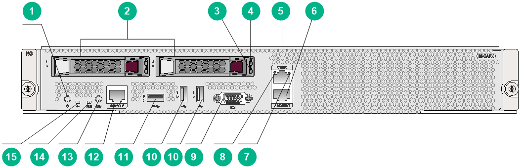
|
No. |
Description |
|
(1) |
Power on/standby button and system power LED |
|
(2) |
2.5 in SATA drive slot |
|
(3) |
Drive Present/Active LED |
|
(4) |
Drive Fault/UID LED |
|
(5) |
BMC network port (1 Gb, RJ45) with default IP 192.168.1.2/24 |
|
(6) |
Shared network port, which can be used as the following: · Ethernet port (1Gb, RJ45) · BMC network port (1Gb, RJ45), with default IP automatically obtained through DHCP) |
|
(7) |
BMC network port status LED |
|
(8) |
Shared network port status LED |
|
(9) |
VGA connector |
|
(10) |
USB 2.0 port |
|
(11) |
USB 3.0 port |
|
(12) |
Console port |
|
(13) |
UID LED |
|
(14) |
RUN LED |
|
(15) |
Health LED |
LEDs
Table2-512 System power LED description
|
LED |
Status |
Description |
|
Power on/standby button and system power LED |
Steady green |
The system has started up. |
|
Flashing green (1 Hz) |
The system is starting up. |
|
|
Steady amber |
The system is in standby mode. |
|
|
Off |
The system is powered off. |
Table2-513 Health LED description
|
LED |
Status |
Description |
|
Health LED |
Steady green |
The system is operating correctly. |
|
Flashing green (4 Hz) |
The BMC is currently resetting and initializing. |
|
|
Flashing yellow and green (1 Hz) |
A minor alarm occurs in the system, including an alarm on an error monitored by BMC or an alarm on hardware. |
|
|
Flashing yellow (1 Hz) |
A major alarm occurs in the system, including an alarm on an error monitored by BMC, an alarm on hardware or CPU. |
Table2-514 RUN LED description
|
LED |
Status |
Description |
|
RUN LED |
Steady on |
The card is faulty. |
|
Off |
The card is faulty or is not in position. |
|
|
Flashing (1 Hz) |
The card is operating correctly. |
|
|
Fast flashing |
The card is starting up. If the LED keeps fast flashing, card registration has failed. |
Table2-515 UID LED description
|
LED |
Status |
Description |
|
UID LED |
Steady blue |
The UID LED is activated. You can activate the UID LED in the following methods: · Press down the UID LED. · Power on the UID LED from BMC. |
|
Flashing blue |
· 1 Hz: The system is being remote managed by BMC or performing software update. · 4Hz: BMC is restarting by pressing the UID button or LED for 8 seconds. |
|
|
Off |
The UID LED is not activated. |
Table2-516 Drive LED description
|
Fault/UID LED (orange/blue) |
Present/Active LED (green) |
Description |
|
Flashing orange (0.5 Hz) |
Steady green/flashing green (4 Hz) |
A predictive alarm occurs on the drive. Replace the drive in time.* |
|
Steady orange |
Steady green/flashing green (4 Hz) |
An error occurs on the drive. Replace the drive immediately. |
|
Steady blue |
Steady green/flashing green (4 Hz) |
The drive is operating correctly and has been selected by the array management tool. |
|
Off |
Flashing (4 Hz) |
The drive is present. Data is being read from or written to the drive, or the drive is being used for array migration or rebuilding. |
|
Off |
Steady on |
The drive is present but no data being read from or written to the drive. |
|
Off |
Off |
The drive is not installed properly. |
Table2-517 BMC network port LED description
|
LED |
Status |
Description |
|
BMC network port LED |
Steady green |
The network port is being activated. |
|
Flashing green (1 Hz) |
The network port is receiving or sending data. |
|
|
Off |
The network port is disconnected. |
Table2-518 Shared network port LED description
|
LED |
Status |
Description |
|
Shared network port LED |
Steady green |
The network port is being activated. |
|
Flashing green (1 Hz) |
The network port is receiving or sending data. |
|
|
Off |
The network port is disconnected. |
Ports
Table2-519 Port specifications
|
Card model |
Description |
|
IM-OAPX |
Universal open application platform |
Technical specifications
Table2-520 Technical specifications
|
Item |
Description |
|
Dimensions (H × W × D) |
52.5 × 399 × 352 mm (2.07 × 15.71 × 13.86 in) |
|
Weight |
6.25 kg (13.78 lb) |
|
Maximum power consumption |
320 W |
|
Power consumption (with typical configuration) |
310 W |
|
Minimum power consumption |
295 W |
|
Operating temperature |
0°C to 45°C (32°F to 113°F) |
|
Processor |
Intel Skylake Xeon CPU · A maximum power consumption of 205 W · A maximum of 2.6 GHz CPU clock speed · 38.5 MB cache |
|
Memory |
Support six DDR4 memory modules · Single DIMM capacity: 32 GB · Total memory capacity: 192 GB |
|
Storage |
Maximum storage capacity: 2 × 960 GB |
|
Chipset |
Intel C62x Lewisburg chipset compatible with LBG-T SKU |
|
User port |
· 2 × console ports · 1 × BMC network port · 1 × shared network port (used as an Ethernet port or a BMC network port) · 1 × VGA connector · 1 × USB port (USB 3.0) · 2 × USB ports (USB 2.0) |
Table2-521 Drive specifications
|
Model |
Capacity |
Interface type |
Interface rate |
|
UIS-SSD-960GB-SATA-6G-SFF-EV |
960 G |
SATA |
6 Gbps |
|
UN-SSD-960G-SATA-6G-SFF-EV-1 |
960 G |
SATA |
6 Gbps |
Configuration restrictions and guidelines
· To avoid data loss on drives, you must shut down the universal open application platform before performing the following operations:
¡ Reboot or hot plug the universal open application platform.
¡ Reboot or shut down the router.
· Do not install the universal open application platform in slot 6 of the CR16010-F router or slot 8 of the CR16014-F router.
· The console port on the panel of the universal open application platform is only for users. The internal console port of the universal open application platform is only for H3C Support to perform maintenance and updates. Operations without permission are not allowed. H3C will not be liable for any consequences caused thereby.
· The shared network interface can operate only at 1000 Mbps and can be connected only with a GE port.
· USB ports do not support extension cables.
Compatibility information
Table2-522 Compatibility matrix between the universal open application platform and routers
|
Card model |
CR16006-F |
CR16010-F, CR16014-F |
CR16010H-F (with five fabric modules), CR16018-F (with five fabric modules) |
CR16010H-F (with four fabric modules), CR16018-F (with four fabric modules) |
CR16010H-FA, CR16018-FA |
CR16003E-F, CR16005E-F, CR16010E-F |
|
IM-OAPX |
Supported |
Supported |
Supported |
Not supported |
Not supported |
Supported |
Switching fabric modules
CSFC-04-1/CSFC-04-2/CSFC-04-3/CSFC-04-4
View
Figure2-134 CSFC-04-1 view

The views of CSFC-04-1, CSFC-04-2, CSFC-04-3, and CSFC-04-4 are similar. This figure uses the CSFC-04-1 as an example.
Technical specifications
Table2-523 Technical specifications
|
Item |
Description |
|
Dimensions (H × W × D) |
40 × 256 × 298 mm (1.57 × 10.08 × 11.73 in) |
|
Weight |
1.00 kg (2.20 lb) |
|
Maximum power consumption |
N/A |
|
Minimum power consumption |
N/A |
|
Operating temperature |
0°C to 45°C (32°F to 113°F) |
CSFC-04B/CSFC-04D
View
Figure2-135 CSFC-04B view
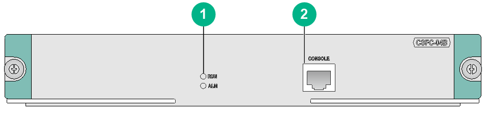
|
(1) Switching fabric module status LED. For the LED description, see Table2-524. |
(2) Console port |
The views of CSFC-04B and CSFC-04D are similar. This figure uses the CSFC-04B as an example.
LEDs
Table2-524 Switching fabric module status LED description
|
LED status |
Description |
|
|
RUN |
ALM |
|
|
Flashing (0.5 Hz) |
Off |
The switching fabric module is operating correctly. |
|
Off |
Steady on |
The switching fabric module is faulty. |
|
Flashing (0.5 Hz) |
Steady on |
The temperature of the switching fabric module has exceeded the upper limit or dropped below the lower limit. |
|
Off |
Off |
The switching fabric module has not started up. |
|
Steady on |
Off |
The switching fabric module is starting up. |
Technical specifications
Table2-525 Technical specifications
|
Item |
Description |
|
Dimensions (H × W × D) |
40 × 256 × 298 mm (1.57 × 10.08 × 11.73 in) |
|
Weight |
· CSFC-04B: 1.75 kg (3.86 lb) · CSFC-04D: 1.71 kg (3.77 lb) |
|
Maximum power consumption |
· CSFC-04B: 65 W · CSFC-04D: 80 W |
|
Power consumption (with typical configuration) |
· CSFC-04B: 59 W · CSFC-04D: 72 W |
|
Minimum power consumption |
· CSFC-04B: 48 W · CSFC-04D: 60 W |
|
Operating temperature |
0°C to 45°C (32°F to 113°F) |
CSFC-08B/CSFC-08D
View
Figure2-136 CSFC-08B view

|
(1) Console port |
(2) Switching fabric module status LED. For the LED description, see Table2-526. |
The views of the CSFC-08B and CSFC-08D are similar. This figure uses the CSFC-08B as an example.
LEDs
Table2-526 Switching fabric module status LED description
|
LED status |
Description |
|
|
RUN |
ALM |
|
|
Flashing (0.5 Hz) |
Off |
The switching fabric module is operating correctly. |
|
Off |
Steady on |
The switching fabric module is faulty. |
|
Flashing (0.5 Hz) |
Steady on |
The temperature of the switching fabric module has exceeded the upper limit or dropped below the lower limit. |
|
Off |
Off |
The switching fabric module has not started up. |
|
Steady on |
Off |
The switching fabric module is starting up. |
Technical specifications
Table2-527 Technical specifications
|
Item |
Description |
|
Dimensions (H × W × D) |
40 × 426 × 298 mm (1.57 × 16.77 × 11.73 in) |
|
Weight |
· CSFC-08B: 2.50 kg (5.51 lb) · CSFC-08D: 2.77 kg (6.11 lb) |
|
Maximum power consumption |
· CSFC-08B: 60 W · CSFC-08D: 135 W |
|
Power consumption (with typical configuration) |
· CSFC-08B: 54 W · CSFC-08D: 122 W |
|
Minimum power consumption |
· CSFC-08B: 44 W · CSFC-08D: 101 W |
|
Operating temperature |
0°C to 45°C (32°F to 113°F) |
CSFC-12B/CSFC-12D
View
Figure2-137 CSFC-12B view
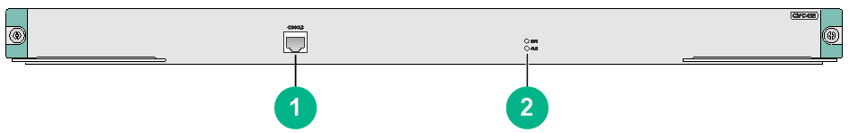
|
(1) Console port |
(2) Switching fabric module status LED. For the LED description, see Table2-528. |
The views of the CSFC-12B and CSFC-12D are similar. This figure uses the CSFC-12B as an example.
LEDs
Table2-528 Switching fabric module status LED description
|
LED status |
Description |
|
|
RUN |
ALM |
|
|
Flashing (0.5 Hz) |
Off |
The switching fabric module is operating correctly. |
|
Off |
Steady on |
The switching fabric module is faulty. |
|
Flashing (0.5 Hz) |
Steady on |
The temperature of the switching fabric module has exceeded the upper limit or dropped below the lower limit. |
|
Off |
Off |
The switching fabric module has not started up. |
|
Steady on |
Off |
The switching fabric module is starting up. |
Technical specifications
Table2-529 Technical specifications
|
Item |
Description |
|
Dimensions (H × W × D) |
40 × 602 × 298 mm (1.57 × 23.70 × 11.73 in) |
|
Weight |
· CSFC-12B: 3.89 kg (8.58 lb) · CSFC-12D: 4.51 kg (9.94 lb) |
|
Maximum power consumption |
· CSFC-12B: 140 W · CSFC-12D: 255 W |
|
Power consumption (with typical configuration) |
· CSFC-12B: 126 W · CSFC-12D: 230 W |
|
Minimum power consumption |
· CSFC-12B: 107 W · CSFC-12D: 195 W |
|
Operating temperature |
0°C to 45°C (32°F to 113°F) |
CSFC-08E
View
Figure2-138 CSFC-08E view

|
(1) Switching fabric module status LED. For the LED description, see Table2-530. |
LEDs
Table2-530 Switching fabric module status LED description
|
LED status |
Description |
|
|
RUN |
ALM |
|
|
Flashing (0.5 Hz) |
Off |
The switching fabric module is operating correctly. |
|
Off |
Steady on |
The switching fabric module is faulty. |
|
Flashing (0.5 Hz) |
Steady on |
The temperature of the switching fabric module has exceeded the upper limit or dropped below the lower limit. |
|
Off |
Off |
The switching fabric module has not started up. |
|
Steady on |
Off |
The switching fabric module is starting up. |
Technical specifications
Table2-531 Technical specifications
|
Item |
Description |
|
Dimensions (H × W × D) |
40 × 426 × 298 mm (1.57 × 16.77 × 11.73 in) |
|
Weight |
3.55 kg (7.83 lb) |
|
Maximum power consumption |
140 W |
|
Power consumption (with typical configuration) |
130 W |
|
Minimum power consumption |
73 W |
|
Operating temperature |
0°C to 45°C (32°F to 113°F) |
CSFC-08E1/CSFC-08E1A/CSFC-08T
View
Figure2-139 CSFC-08E1 view
|
(1) Switching fabric module status LED. For the LED description, see Table2-532. |
The views of the CSFC-08E1, CSFC-08E1A and CSFC-08T are similar. This figure uses the CSFC-08E1 as an example.
LEDs
Table2-532 Switching fabric module status LED description
|
RUN LED status |
Description |
|
Flashing (0.5 Hz) |
The switching fabric module is operating correctly. |
|
Flashing (8 Hz) |
The switching fabric module is starting up. |
|
Off |
The switching fabric module has not started up. |
Technical specifications
Table2-533 Technical specifications
|
Item |
Description |
|
Dimensions (H × W × D) |
40 × 562 × 298 mm (1.57 × 22.13 × 11.73 in) |
|
Weight |
· CSFC-08E1, CSFC-08E1A: 5.20 kg (11.46 lb) · CSFC-08T: 5.15 kg (11.35 lb) |
|
Maximum power consumption |
· CSFC-08E1: 125 W · CSFC-08E1A, CSFC-08T: 129 W |
|
Power consumption (with typical configuration) |
· CSFC-08E1: 112 W · CSFC-08E1A, CSFC-08T: 116 W |
|
Minimum power consumption |
· CSFC-08E1: 75 W · CSFC-08E1A, CSFC-08T: 100 W |
|
Operating temperature |
0°C to 45°C (32°F to 113°F) |
CSFC-08E2A/CSFC-08E3A
View
Figure2-140 CSFC-08E2A view

|
(1) Switching fabric module status LED. For the LED description, see Table2-534. |
The views of the CSFC-08E2A and CSFC-08E3A are similar. This figure uses the CSFC-08E2A as an example.
LEDs
Table2-534 Switching fabric module status LED description
|
RUN LED status |
Description |
|
Flashing (0.5 Hz) |
The switching fabric module is operating correctly. |
|
Flashing (8 Hz) |
The switching fabric module is starting up. |
|
Off |
The switching fabric module has not started up. |
Technical specifications
Table2-535 Technical specifications
|
Item |
Description |
|
Dimensions (H × W × D) |
40 × 562 × 298 mm (1.57 × 22.13 × 11.73 in) |
|
Weight |
5.20 kg (11.46 lb) |
|
Maximum power consumption |
220 W |
|
Power consumption (with typical configuration) |
200 W |
|
Minimum power consumption |
162 W |
|
Operating temperature |
0°C to 45°C (32°F to 113°F) |
CSFC-12E
View
Figure2-141 CSFC-12E view

|
(1) Console port |
(2) Air inlet vents |
|
(3) Switching fabric module status LED. For the LED description, see Table2-536. |
|
LEDs
Table2-536 Switching fabric module status LED description
|
LED status |
Description |
|
|
RUN |
ALM |
|
|
Flashing (0.5 Hz) |
Off |
The switching fabric module is operating correctly. |
|
Off |
Steady on |
The switching fabric module is faulty. |
|
Flashing (0.5 Hz) |
Steady on |
The temperature of the switching fabric module has exceeded the upper limit or dropped below the lower limit. |
|
Off |
Off |
The switching fabric module has not started up. |
|
Steady on |
Off |
The switching fabric module is starting up. |
Technical specifications
Table2-537 Technical specifications
|
Item |
Description |
|
Dimensions (H × W × D) |
40 × 602 × 298 mm (1.57 × 23.70 × 11.73 in) |
|
Weight |
5.30 kg (11.68 lb) |
|
Maximum power consumption |
178 W |
|
Power consumption (with typical configuration) |
161 W |
|
Minimum power consumption |
146 W |
|
Operating temperature |
0°C to 45°C (32°F to 113°F) |
CSFC-16T/CSFC-16T1/CSFC-16E/CSFC-16EA
View
Figure2-142 CSFC-16T1 view
|
(1) Switching fabric module status LED. For the LED description, see Table2-538. |
The views of the CSFC-16T, CSFC-16T1, CSFC-16E, and CSFC-16EA are similar. This figure uses the CSFC-16T1 as an example.
LEDs
Table2-538 Switching fabric module status LED description
|
RUN LED status |
Description |
|
Flashing (0.5 Hz) |
The switching fabric module is operating correctly. |
|
Flashing (8 Hz) |
The switching fabric module is starting up. |
|
Off |
The switching fabric module has not started up. |
Technical specifications
Table2-539 Technical specifications
|
Item |
Description |
|
Dimensions (H × W × D) |
40 × 961 × 298 mm (1.57 × 37.83 × 11.73 in) |
|
Weight |
· CSFC-16T: 10.25 kg (22.60 lb) · CSFC-16T1: 10.35 kg (22.82 lb) · CSFC-16E, CSFC-16EA: 10.50 kg (23.15 lb) |
|
Maximum power consumption |
· CSFC-16T: 402 W · CSFC-16E: 248 W · CSFC-16E: 248 W · CSFC-16EA: 402W |
|
Power consumption (with typical configuration) |
· CSFC-16T: 361 W · CSFC-16T1: 245 W · CSFC-16E: 220 W · CSFC-16EA: 361 W |
|
Minimum power consumption |
· CSFC-16T: 267 W · CSFC-16T1: 210 W · CSFC-16E: 159 W · CSFC-16EA: 267 W |
|
Operating temperature |
0°C to 45°C (32°F to 113°F) |
CSFC-16E2A/CSFC-16E3A
View
Figure2-143 CSFC-16E2A view
|
(1) Switching fabric module status LED. For the LED description, see Table2-540. |
The views of the CSFC-16E2A and CSFC-16E3A are similar. This figure uses the CSFC-16E2A as an example.
LEDs
Table2-540 Switching fabric module status LED description
|
RUN LED status |
Description |
|
Flashing (0.5 Hz) |
The switching fabric module is operating correctly. |
|
Flashing (8 Hz) |
The switching fabric module is starting up. |
|
Off |
The switching fabric module has not started up. |
Technical specifications
Table2-541 Technical specifications
|
Item |
Description |
|
Dimensions (H × W × D) |
40 × 961 × 298 mm (1.57 × 37.83 × 11.73 in) |
|
Weight |
10.35 kg (22.82 lb) |
|
Maximum power consumption |
600 W |
|
Power consumption (with typical configuration) |
380 W |
|
Minimum power consumption |
256 W |
|
Operating temperature |
0°C to 45°C (32°F to 113°F) |
CSFC-08T-G
View
Figure2-144 CSFC-08T-G view
|
(1) Switching fabric module status LED. For the LED description, see Table2-542. |
LEDs
Table2-542 Switching fabric module status LED description
|
RUN LED status |
Description |
|
Flashing (0.5 Hz) |
The switching fabric module is operating correctly. |
|
Flashing (8 Hz) |
The switching fabric module is starting up. |
|
Off |
The switching fabric module has not started up. |
Technical specifications
Table2-543 Technical specifications
|
Item |
Description |
|
Dimensions (H × W × D) |
40 × 562 × 298 mm (1.57 × 22.13 × 11.73 in) |
|
Weight |
5.30 kg (11.68 lb) |
|
Maximum power consumption |
130 W |
|
Power consumption (with typical configuration) |
110 W |
|
Minimum power consumption |
100 W |
|
Operating temperature |
0°C to 45°C (32°F to 113°F) |
CSFC-16T-G
View
Figure2-145 CSFC-16T-G view
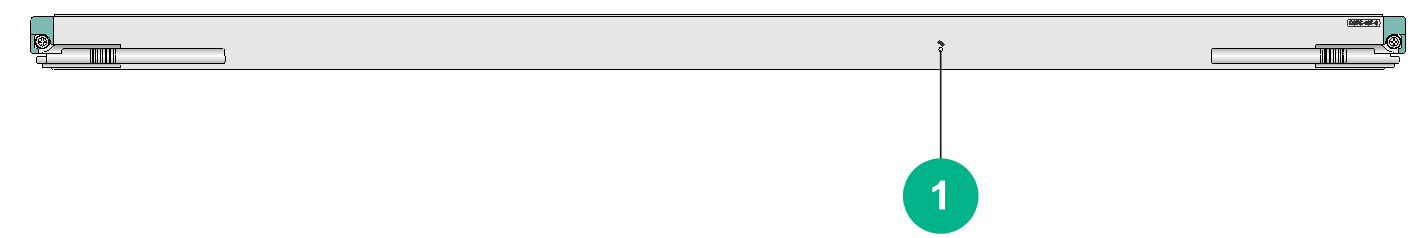
|
(1) Switching fabric module status LED. For the LED description, see Table2-544. |
LEDs
Table2-544 Switching fabric module status LED description
|
RUN LED status |
Description |
|
Flashing (0.5 Hz) |
The switching fabric module is operating correctly. |
|
Flashing (8 Hz) |
The switching fabric module is starting up. |
|
Off |
The switching fabric module has not started up. |
Technical specifications
Table2-545 Technical specifications
|
Item |
Description |
|
Dimensions (H × W × D) |
40 × 961 × 298 mm (1.57 × 37.83 × 11.73 in) |
|
Weight |
10.30 kg (22.71 lb) |
|
Maximum power consumption |
120 W |
|
Power consumption (with typical configuration) |
110 W |
|
Minimum power consumption |
100 W |
|
Operating temperature |
0°C to 45°C (32°F to 113°F) |
CSFC-10T-G
View
Figure2-146 CSFC-10T-G view
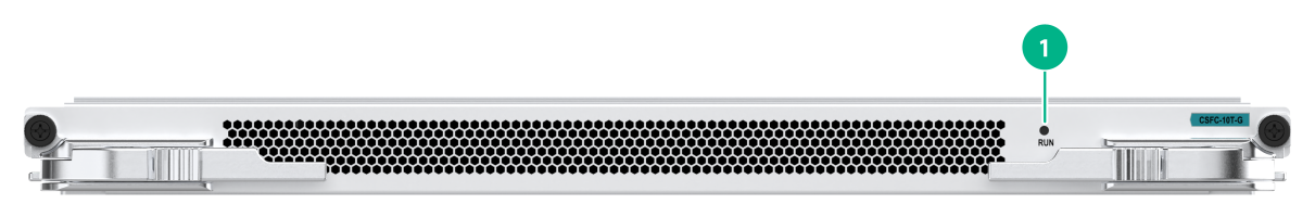
|
(1) Switching fabric module status LED. For the LED description, see Table2-546. |
LEDs
Table2-546 Switching fabric module status LED description
|
RUN LED status |
Description |
|
Flashing (0.5 Hz) |
The switching fabric module is operating correctly. |
|
Flashing (8 Hz) |
The switching fabric module is starting up. |
|
Off |
The switching fabric module has not started up. |
Technical specifications
Table2-547 Technical specifications
|
Item |
Description |
|
Dimensions (H × W × D) |
29 × 399.2 × 353.6 mm (1.14 × 15.72 × 13.92 in) |
|
Weight |
3.65 kg (8.05 lb) |
|
Maximum power consumption |
120 W |
|
Power consumption (with typical configuration) |
81 W |
|
Minimum power consumption |
72 W |
|
Operating temperature |
0°C to 45°C (32°F to 113°F) |
CSFC-10E-G
View
Figure2-147 CSFC-10E-G view
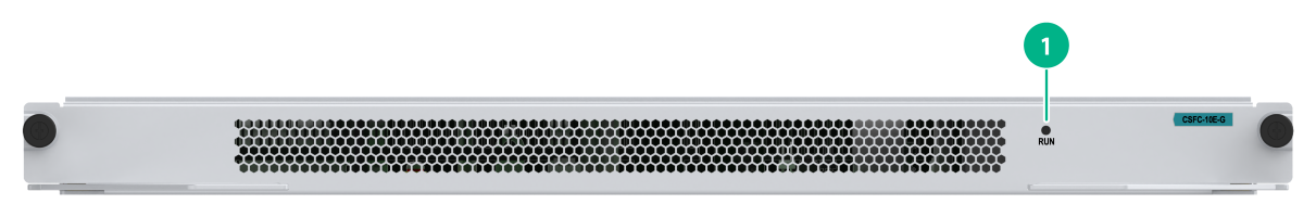
|
(1) Switching fabric module status LED. For the LED description, see Table2-548. |
LEDs
Table2-548 Switching fabric module status LED description
|
RUN LED status |
Description |
|
Flashing (0.5 Hz) |
The switching fabric module is operating correctly. |
|
Flashing (8 Hz) |
The switching fabric module is starting up. |
|
Off |
The switching fabric module has not started up. |
Technical specifications
Table2-549 Technical specifications
|
Item |
Description |
|
Dimensions (H × W × D) |
29 × 399.2 × 353.6 mm (1.14 × 15.72 × 13.92 in) |
|
Weight |
3.20 kg (7.05 lb) |
|
Maximum power consumption |
30 W |
|
Power consumption (with typical configuration) |
19 W |
|
Minimum power consumption |
14 W |
|
Operating temperature |
0°C to 45°C (32°F to 113°F) |
Configuration restrictions and guidelines
· Do not install switching fabric modules of different types on the same router.
· If you use Type-B, Type-D, Type-E, Type-T, or Type-TG switching fabric modules for the router, a minimum of two are required. For a CR16010H-F (with five fabric modules) or CR16010H-FA router, you must install switching fabric modules in slots 10 and 12. Slot 11 can be used only when five switching fabric modules are required. For a CR16018-F (with five fabric modules) or CR16018-FA router, you must install switching fabric modules in slots 18 and 20. Slot 19 can be used only when five switching fabric modules are required. For other routers, slots 1, 3, and 4 take precedence over the other slots.
· The console port on a switching fabric module is only for H3C Support to perform maintenance and updates. Operations without permission are not allowed. H3C will not be liable for any consequences caused thereby.
· If Type-A switching fabric modules are used, use the four together and install each into the specified slot. Each Type-A switching fabric module has a mark specifying the slot for installation. For example, the CSFC-04-1 has the mark Notes:Please insert to Slot 6.
Compatibility information
Table2-550 Compatibility matrix between switching fabric modules and routers
|
Chassis model |
Available switching fabric module model |
Number |
|
CR16006-F |
Type-A: CSFC-04-1, CSFC-04-2, CSFC-04-3, CSFC-04-4 |
4 (1 for each switching fabric module model) |
|
· Type-B: CSFC-04B · Type-D: CSFC-04D |
2 to 4 |
|
|
CR16010-F |
· Type-B: CSFC-08B · Type-D: CSFC-08D · Type-E: CSFC-08E |
2 to 4 |
|
CR16010H-F (with five fabric modules) |
· Type-E: CSFC-08E1 · Type-T: CSFC-08T · Type-TG: CSFC-08T-G |
2 to 5 |
|
CR16010H-F (with four fabric modules) |
· Type-E: CSFC-08E1 · Type-T: CSFC-08T · Type-TG: CSFC-08T-G |
2 to 4 |
|
CR16010H-FA |
Type-E: CSFC-08E1A, CSFC-08E2A, CSFC-08E3A |
2 to 5 |
|
CR16014-F |
· Type-B: CSFC-12B · Type-D: CSFC-12D · Type-E: CSFC-12E |
2 to 4 |
|
CR16018-F (with five fabric modules) |
· Type-E: CSFC-16E · Type-T: CSFC-16T, CSFC-16T1 · Type-TG: CSFC-16T-G |
2 to 5 |
|
CR16018-F (with four fabric modules) |
· Type-E: CSFC-16E · Type-T: CSFC-16T, CSFC-16T1 · Type-TG: CSFC-16T-G |
2 to 4 |
|
CR16018-FA |
Type-E: CSFC-16EA, CSFC-16E2A, CSFC-16E3A |
2 to 5 |
|
CR16010E-F |
· Type-T: CSFC-10T-G · Type-E: CSFC-10E-G |
1 to 2 |
Table2-551 Compatibility matrix between switching fabric modules and service modules (1)
|
Service module |
Type-A switching fabric module |
CSFC-04B |
CSFC-04D |
CSFC-08B |
CSFC-08D |
|
CSPC-GT48LA1 |
Supported |
Supported |
Supported |
Supported |
Supported |
|
CSPC-GE24L-E |
Supported |
Supported |
Supported |
Supported |
Supported |
|
CSPC-GP24LA1 |
Supported |
Supported |
Supported |
Supported |
Supported |
|
CSPC-GP48LB |
Supported |
Supported |
Supported |
Supported |
Supported |
|
CSPC-GP24XP2LB |
Supported |
Supported |
Supported |
Supported |
Supported |
|
CSPC-GP24GE8XP2L-E |
Supported |
Supported |
Supported |
Supported |
Supported |
|
CSPC-GE16XP4L-E |
Supported |
Supported |
Supported |
Supported |
Supported |
|
CSPC-GP44XP4LCX |
Not supported |
Supported |
Supported |
Supported |
Supported |
|
CSPC-XP2LA1 |
Supported |
Supported |
Supported |
Supported |
Supported |
|
CSPC-XP4LB |
Supported |
Supported |
Supported |
Supported |
Supported |
|
CSPC-XP8LB |
Supported |
Supported |
Supported |
Supported |
Supported |
|
CSPC-XP12LAX |
Not supported |
Supported |
Supported |
Supported |
Supported |
|
CSPC-XP12LCX |
Not supported |
Supported |
Supported |
Supported |
Supported |
|
CSPC-XP24LAX |
Not supported |
Supported |
Supported |
Supported |
Supported |
|
CSPC-XP24LCX |
Not supported |
Supported |
Supported |
Supported |
Supported |
|
CSPC-XLP6LCX |
Not supported |
Supported |
Supported |
Supported |
Supported |
|
CSPC-CP1LCX |
Not supported |
Supported |
Supported |
Supported |
Supported |
|
CSPC-CP2LB |
Not supported |
Supported |
Supported |
Supported |
Supported |
|
CEPC-CP4RX |
Not supported |
Not supported |
Not supported |
Not supported |
Not supported |
|
CEPC-CP4RXA |
Not supported |
Not supported |
Not supported |
Not supported |
Not supported |
|
CEPC-CP4RX-L |
Not supported |
Not supported |
Not supported |
Not supported |
Not supported |
|
CEPC-CQ8L |
Not supported |
Not supported |
Not supported |
Not supported |
Not supported |
|
CEPC-CQ8LA |
Not supported |
Not supported |
Not supported |
Not supported |
Not supported |
|
CEPC-CQ8L1A |
Not supported |
Not supported |
Not supported |
Not supported |
Not supported |
|
CEPC-CQ8L3A |
Not supported |
Not supported |
Not supported |
Not supported |
Not supported |
|
CEPC-CQ16L1 |
Not supported |
Not supported |
Not supported |
Not supported |
Not supported |
|
CEPC-DQ2L1-G |
Not supported |
Not supported |
Not supported |
Not supported |
Not supported |
|
CEPC-XP4LX |
Not supported |
Supported |
Supported |
Supported |
Supported |
|
CEPC-XP24LX |
Not supported |
Not supported |
Not supported |
Not supported |
Not supported |
|
CEPC-XP48RX |
Not supported |
Not supported |
Not supported |
Not supported |
Not supported |
|
CSPEX-1204 |
Supported |
Supported |
Supported |
Supported |
Supported |
|
CSPEX-1104-E |
Supported |
Supported |
Supported |
Supported |
Supported |
|
CSPEX-1304X |
Not supported |
Supported |
Supported |
Supported |
Supported |
|
CSPEX-1404X |
Not supported |
Supported |
Supported |
Supported |
Supported |
|
CSPEX-1502X |
Not supported |
Not supported |
Not supported |
Not supported |
Not supported |
|
CSPEX-1502XA |
Not supported |
Not supported |
Not supported |
Not supported |
Not supported |
|
CSPEX-1504X |
Not supported |
Supported |
Supported |
Supported |
Supported |
|
CSPEX-1504XA |
Not supported |
Not supported |
Not supported |
Not supported |
Not supported |
|
CSPEX-1602X |
Not supported |
Not supported |
Not supported |
Not supported |
Not supported |
|
CSPEX-1602XA |
Not supported |
Not supported |
Not supported |
Not supported |
Not supported |
|
CSPEX-1802X |
Not supported |
Not supported |
Not supported |
Not supported |
Not supported |
|
CSPEX-1802XA |
Not supported |
Not supported |
Not supported |
Not supported |
Not supported |
|
CSPEX-1804X |
Not supported |
Not supported |
Not supported |
Not supported |
Not supported |
|
CSPEX-1512X |
Not supported |
Not supported |
Not supported |
Not supported |
Not supported |
|
CSPEX-1612X |
Not supported |
Not supported |
Not supported |
Not supported |
Not supported |
|
CSPEX-1812X |
Not supported |
Not supported |
Not supported |
Not supported |
Not supported |
|
CSPEX-1812X-E |
Not supported |
Not supported |
Not supported |
Not supported |
Not supported |
|
CSPEX-2304X-G |
Not supported |
Supported |
Supported |
Not supported |
Not supported |
|
CSPEX-2304X-LG |
Not supported |
Supported |
Supported |
Not supported |
Not supported |
|
CSPEX-2314X-G |
Not supported |
Not supported |
Not supported |
Not supported |
Not supported |
|
CSPEX-2314X-G1 |
Not supported |
Not supported |
Not supported |
Not supported |
Not supported |
|
CSPEX-2314X-G2 |
Not supported |
Not supported |
Not supported |
Not supported |
Not supported |
|
CSPEX-2612XA |
Not supported |
Not supported |
Not supported |
Not supported |
Not supported |
|
CSPEX-2612X3A |
Not supported |
Not supported |
Not supported |
Not supported |
Not supported |
|
CMPE-1104 |
Supported |
Supported |
Supported |
Supported |
Supported |
|
RX-SPE200 |
Not supported |
Not supported |
Not supported |
Not supported |
Not supported |
|
RX-SPE200-E |
Not supported |
Not supported |
Not supported |
Not supported |
Not supported |
|
IM-NGFWX-IV |
Not supported |
Supported |
Supported |
Supported |
Supported |
|
LSU1FWCEA0 |
Supported |
Supported |
Supported |
Supported |
Supported |
|
LSU3FWCEA0 |
Supported |
Supported |
Supported |
Supported |
Supported |
|
IM-IPSX-IV |
Not supported |
Supported |
Supported |
Supported |
Supported |
|
LSU1IPSBEA0 |
Supported |
Supported |
Supported |
Supported |
Supported |
|
IM-ACG1000X-IV |
Not supported |
Supported |
Supported |
Supported |
Supported |
|
LSU1ADECEA0 |
Supported |
Supported |
Supported |
Supported |
Supported |
|
IM-APA-I |
Not supported |
Not supported |
Not supported |
Not supported |
Not supported |
|
IM-MSUX (1U) |
Not supported |
Supported |
Supported |
Supported |
Supported |
|
IM-MSUX (1.2U) |
Not supported |
Not supported |
Not supported |
Not supported |
Not supported |
|
IM-MSEX-B |
Not supported |
Not supported |
Not supported |
Not supported |
Not supported |
|
IM-SMUX |
Not supported |
Supported |
Supported |
Supported |
Supported |
|
IM-SFMX |
Not supported |
Supported |
Supported |
Supported |
Supported |
|
IM-OAPX |
Not supported |
Supported |
Supported |
Supported |
Supported |
Table2-552 Compatibility matrix between switching fabric modules and service modules (2)
|
Service module |
CSFC-12B CSFC-12D |
CSFC-08E |
CSFC-08E1 |
CSFC-08E1A |
CSFC-08E2A |
|
CSPC-GT48LA1 |
Supported |
Not supported |
Not supported |
Not supported |
Not supported |
|
CSPC-GE24L-E |
Supported |
Not supported |
Not supported |
Not supported |
Not supported |
|
CSPC-GP24LA1 |
Supported |
Not supported |
Not supported |
Not supported |
Not supported |
|
CSPC-GP48LB |
Supported |
Not supported |
Not supported |
Not supported |
Not supported |
|
CSPC-GP24XP2LB |
Supported |
Not supported |
Not supported |
Not supported |
Not supported |
|
CSPC-GP24GE8XP2L-E |
Supported |
Not supported |
Not supported |
Not supported |
Not supported |
|
CSPC-GE16XP4L-E |
Supported |
Not supported |
Not supported |
Not supported |
Not supported |
|
CSPC-GP44XP4LCX |
Supported |
Not supported |
Not supported |
Not supported |
Not supported |
|
CSPC-XP2LA1 |
Supported |
Not supported |
Not supported |
Not supported |
Not supported |
|
CSPC-XP4LB |
Supported |
Not supported |
Not supported |
Not supported |
Not supported |
|
CSPC-XP8LB |
Supported |
Not supported |
Not supported |
Not supported |
Not supported |
|
CSPC-XP12LAX |
Supported |
Not supported |
Not supported |
Not supported |
Not supported |
|
CSPC-XP12LCX |
Supported |
Not supported |
Not supported |
Not supported |
Not supported |
|
CSPC-XP24LAX |
Supported |
Not supported |
Not supported |
Not supported |
Not supported |
|
CSPC-XP24LCX |
Supported |
Not supported |
Not supported |
Not supported |
Not supported |
|
CSPC-XLP6LCX |
Supported |
Not supported |
Not supported |
Not supported |
Not supported |
|
CSPC-CP1LCX |
Supported |
Not supported |
Not supported |
Not supported |
Not supported |
|
CSPC-CP2LB |
Supported |
Not supported |
Not supported |
Not supported |
Not supported |
|
CEPC-CP4RX |
Not supported |
Supported |
Supported |
Not supported |
Not supported |
|
CEPC-CP4RXA |
Not supported |
Not supported |
Not supported |
Supported |
Not supported |
|
CEPC-CP4RX-L |
Not supported |
Supported |
Supported |
Not supported |
Not supported |
|
CEPC-CQ8L |
Not supported |
Not supported |
Not supported |
Not supported |
Not supported |
|
CEPC-CQ8LA |
Not supported |
Not supported |
Not supported |
Supported |
Supported |
|
CEPC-CQ8L1A |
Not supported |
Not supported |
Not supported |
Supported |
Supported |
|
CEPC-CQ8L3A |
Not supported |
Not supported |
Not supported |
Supported |
Supported |
|
CEPC-CQ16L1 |
Not supported |
Not supported |
Not supported |
Not supported |
Not supported |
|
CEPC-DQ2L1-G |
Not supported |
Not supported |
Supported |
Not supported |
Not supported |
|
CEPC-XP4LX |
Supported |
Supported |
Supported |
Not supported |
Not supported |
|
CEPC-XP24LX |
Not supported |
Supported |
Supported |
Not supported |
Not supported |
|
CEPC-XP48RX |
Not supported |
Supported |
Supported |
Not supported |
Not supported |
|
CSPEX-1204 |
Supported |
Not supported |
Not supported |
Not supported |
Not supported |
|
CSPEX-1104-E |
Supported |
Not supported |
Not supported |
Not supported |
Not supported |
|
CSPEX-1304X |
Supported |
Supported |
Supported |
Not supported |
Not supported |
|
CSPEX-1404X |
Supported |
Supported |
Supported |
Not supported |
Not supported |
|
CSPEX-1502X |
Not supported |
Supported |
Supported |
Not supported |
Not supported |
|
CSPEX-1502XA |
Not supported |
Not supported |
Not supported |
Supported |
Not supported |
|
CSPEX-1504X |
Supported |
Supported |
Supported |
Not supported |
Not supported |
|
CSPEX-1504XA |
Not supported |
Not supported |
Not supported |
Supported |
Not supported |
|
CSPEX-1602X |
Not supported |
Supported |
Supported |
Not supported |
Not supported |
|
CSPEX-1602XA |
Not supported |
Not supported |
Not supported |
Supported |
Not supported |
|
CSPEX-1802X |
Not supported |
Not supported |
Supported |
Not supported |
Not supported |
|
CSPEX-1802XA |
Not supported |
Not supported |
Supported |
Supported |
Supported |
|
CSPEX-1804X |
Not supported |
Not supported |
Supported |
Not supported |
Not supported |
|
CSPEX-1512X |
Not supported |
Not supported |
Supported |
Not supported |
Not supported |
|
CSPEX-1612X |
Not supported |
Not supported |
Supported |
Not supported |
Not supported |
|
CSPEX-1812X |
Not supported |
Not supported |
Supported |
Not supported |
Not supported |
|
CSPEX-1812X-E |
Not supported |
Not supported |
Supported |
Not supported |
Not supported |
|
CSPEX-2304X-G |
Not supported |
Supported |
Supported |
Not supported |
Not supported |
|
CSPEX-2304X-LG |
Not supported |
Supported |
Supported |
Not supported |
Not supported |
|
CSPEX-2314X-G |
Not supported |
Not supported |
Supported |
Not supported |
Not supported |
|
CSPEX-2314X-G1 |
Not supported |
Not supported |
Supported |
Not supported |
Not supported |
|
CSPEX-2314X-G2 |
Not supported |
Not supported |
Supported |
Not supported |
Not supported |
|
CSPEX-2612XA |
Not supported |
Not supported |
Not supported |
Supported |
Supported |
|
CSPEX-2612X3A |
Not supported |
Not supported |
Not supported |
Supported |
Supported |
|
CMPE-1104 |
Supported |
Not supported |
Not supported |
Not supported |
Not supported |
|
RX-SPE200 |
Not supported |
Not supported |
Supported |
Not supported |
Not supported |
|
RX-SPE200-E |
Not supported |
Not supported |
Supported |
Not supported |
Not supported |
|
IM-NGFWX-IV |
Supported |
Supported |
Supported |
Not supported |
Not supported |
|
LSU1FWCEA0 |
Supported |
Not supported |
Not supported |
Not supported |
Not supported |
|
LSU3FWCEA0 |
Supported |
Not supported |
Not supported |
Not supported |
Not supported |
|
IM-IPSX-IV |
Supported |
Supported |
Supported |
Not supported |
Not supported |
|
LSU1IPSBEA0 |
Supported |
Not supported |
Not supported |
Not supported |
Not supported |
|
IM-ACG1000X-IV |
Supported |
Supported |
Supported |
Not supported |
Not supported |
|
LSU1ADECEA0 |
Supported |
Not supported |
Not supported |
Not supported |
Not supported |
|
IM-APA-I |
Not supported |
Not supported |
Supported |
Not supported |
Not supported |
|
IM-MSUX (1U) |
Supported |
Supported |
Supported |
Not supported |
Not supported |
|
IM-MSUX (1.2U) |
Not supported |
Not supported |
Supported |
Not supported |
Not supported |
|
IM-MSEX-B |
Not supported |
Not supported |
Supported |
Not supported |
Not supported |
|
IM-SMUX |
Supported |
Supported |
Supported |
Not supported |
Not supported |
|
IM-SFMX |
Supported |
Supported |
Supported |
Not supported |
Not supported |
|
IM-OAPX |
Supported |
Supported |
Supported |
Not supported |
Not supported |
Table2-553 Compatibility matrix between switching fabric modules and service modules (3)
|
Service module |
CSFC-08E3A |
CSFC-16EA |
CSFC-16E2A |
CSFC-16E3A |
|
CSPC-GT48LA1 |
Not supported |
Not supported |
Not supported |
Not supported |
|
CSPC-GE24L-E |
Not supported |
Not supported |
Not supported |
Not supported |
|
CSPC-GP24LA1 |
Not supported |
Not supported |
Not supported |
Not supported |
|
CSPC-GP48LB |
Not supported |
Not supported |
Not supported |
Not supported |
|
CSPC-GP24XP2LB |
Not supported |
Not supported |
Not supported |
Not supported |
|
CSPC-GP24GE8XP2L-E |
Not supported |
Not supported |
Not supported |
Not supported |
|
CSPC-GE16XP4L-E |
Not supported |
Not supported |
Not supported |
Not supported |
|
CSPC-GP44XP4LCX |
Not supported |
Not supported |
Not supported |
Not supported |
|
CSPC-XP2LA1 |
Not supported |
Not supported |
Not supported |
Not supported |
|
CSPC-XP4LB |
Not supported |
Not supported |
Not supported |
Not supported |
|
CSPC-XP8LB |
Not supported |
Not supported |
Not supported |
Not supported |
|
CSPC-XP12LAX |
Not supported |
Not supported |
Not supported |
Not supported |
|
CSPC-XP12LCX |
Not supported |
Not supported |
Not supported |
Not supported |
|
CSPC-XP24LAX |
Not supported |
Not supported |
Not supported |
Not supported |
|
CSPC-XP24LCX |
Not supported |
Not supported |
Not supported |
Not supported |
|
CSPC-XLP6LCX |
Not supported |
Not supported |
Not supported |
Not supported |
|
CSPC-CP1LCX |
Not supported |
Not supported |
Not supported |
Not supported |
|
CSPC-CP2LB |
Not supported |
Not supported |
Not supported |
Not supported |
|
CEPC-CP4RX |
Not supported |
Not supported |
Not supported |
Not supported |
|
CEPC-CP4RXA |
Not supported |
Supported |
Not supported |
Not supported |
|
CEPC-CP4RX-L |
Not supported |
Not supported |
Not supported |
Not supported |
|
CEPC-CQ8L |
Not supported |
Not supported |
Not supported |
Not supported |
|
CEPC-CQ8LA |
Not supported |
Supported |
Supported |
Not supported |
|
CEPC-CQ8L1A |
Not supported |
Supported |
Supported |
Not supported |
|
CEPC-CQ8L3A |
Supported |
Supported |
Supported |
Supported |
|
CEPC-CQ16L1 |
Not supported |
Not supported |
Not supported |
Not supported |
|
CEPC-DQ2L1-G |
Not supported |
Not supported |
Not supported |
Not supported |
|
CEPC-XP4LX |
Not supported |
Not supported |
Not supported |
Not supported |
|
CEPC-XP24LX |
Not supported |
Not supported |
Not supported |
Not supported |
|
CEPC-XP48RX |
Not supported |
Not supported |
Not supported |
Not supported |
|
CSPEX-1204 |
Not supported |
Not supported |
Not supported |
Not supported |
|
CSPEX-1104-E |
Not supported |
Not supported |
Not supported |
Not supported |
|
CSPEX-1304X |
Not supported |
Not supported |
Not supported |
Not supported |
|
CSPEX-1404X |
Not supported |
Not supported |
Not supported |
Not supported |
|
CSPEX-1502X |
Not supported |
Not supported |
Not supported |
Not supported |
|
CSPEX-1502XA |
Not supported |
Supported |
Not supported |
Not supported |
|
CSPEX-1504X |
Not supported |
Not supported |
Not supported |
Not supported |
|
CSPEX-1504XA |
Not supported |
Supported |
Not supported |
Not supported |
|
CSPEX-1602X |
Not supported |
Not supported |
Not supported |
Not supported |
|
CSPEX-1602XA |
Not supported |
Supported |
Not supported |
Not supported |
|
CSPEX-1802X |
Not supported |
Not supported |
Not supported |
Not supported |
|
CSPEX-1802XA |
Not supported |
Supported |
Supported |
Not supported |
|
CSPEX-1804X |
Not supported |
Not supported |
Not supported |
Not supported |
|
CSPEX-1512X |
Not supported |
Not supported |
Not supported |
Not supported |
|
CSPEX-1612X |
Not supported |
Not supported |
Not supported |
Not supported |
|
CSPEX-1812X |
Not supported |
Not supported |
Not supported |
Not supported |
|
CSPEX-1812X-E |
Not supported |
Not supported |
Not supported |
Not supported |
|
CSPEX-2304X-G |
Not supported |
Not supported |
Not supported |
Not supported |
|
CSPEX-2304X-LG |
Not supported |
Not supported |
Not supported |
Not supported |
|
CSPEX-2314X-G |
Not supported |
Not supported |
Not supported |
Not supported |
|
CSPEX-2314X-G1 |
Not supported |
Not supported |
Not supported |
Not supported |
|
CSPEX-2314X-G2 |
Not supported |
Not supported |
Not supported |
Not supported |
|
CSPEX-2612XA |
Not supported |
Supported |
Supported |
Not supported |
|
CSPEX-2612X3A |
Supported |
Supported |
Supported |
Supported |
|
CMPE-1104 |
Not supported |
Not supported |
Not supported |
Not supported |
|
RX-SPE200 |
Not supported |
Not supported |
Not supported |
Not supported |
|
RX-SPE200-E |
Not supported |
Not supported |
Not supported |
Not supported |
|
IM-NGFWX-IV |
Not supported |
Not supported |
Not supported |
Not supported |
|
LSU1FWCEA0 |
Not supported |
Not supported |
Not supported |
Not supported |
|
LSU3FWCEA0 |
Not supported |
Not supported |
Not supported |
Not supported |
|
IM-IPSX-IV |
Not supported |
Not supported |
Not supported |
Not supported |
|
LSU1IPSBEA0 |
Not supported |
Not supported |
Not supported |
Not supported |
|
IM-ACG1000X-IV |
Not supported |
Not supported |
Not supported |
Not supported |
|
LSU1ADECEA0 |
Not supported |
Not supported |
Not supported |
Not supported |
|
IM-APA-I |
Not supported |
Not supported |
Not supported |
Not supported |
|
IM-MSUX (1U) |
Not supported |
Not supported |
Not supported |
Not supported |
|
IM-MSUX (1.2U) |
Not supported |
Not supported |
Not supported |
Not supported |
|
IM-MSEX-B |
Not supported |
Not supported |
Not supported |
Not supported |
|
IM-SMUX |
Not supported |
Not supported |
Not supported |
Not supported |
|
IM-SFMX |
Not supported |
Not supported |
Not supported |
Not supported |
|
IM-OAPX |
Not supported |
Not supported |
Not supported |
Not supported |
Table2-554 Compatibility matrix between switching fabric modules and service modules (4)
|
Service module |
CSFC-16E |
CSFC-12E |
CSFC-08T CSFC-16T CSFC-16T1 |
CSFC-08T-G |
CSFC-16T-G |
CSFC-10T-G CSFC-10E-G |
|
CSPC-GT48LA1 |
Not supported |
Not supported |
Not supported |
Not supported |
Not supported |
Not supported |
|
CSPC-GE24L-E |
Not supported |
Not supported |
Not supported |
Not supported |
Not supported |
Not supported |
|
CSPC-GP24LA1 |
Not supported |
Not supported |
Not supported |
Not supported |
Not supported |
Not supported |
|
CSPC-GP48LB |
Not supported |
Not supported |
Not supported |
Not supported |
Not supported |
Not supported |
|
CSPC-GP24XP2LB |
Not supported |
Not supported |
Not supported |
Not supported |
Not supported |
Not supported |
|
CSPC-GP24GE8XP2L-E |
Not supported |
Not supported |
Not supported |
Not supported |
Not supported |
Not supported |
|
CSPC-GE16XP4L-E |
Not supported |
Not supported |
Not supported |
Not supported |
Not supported |
Not supported |
|
CSPC-GP44XP4LCX |
Not supported |
Not supported |
Not supported |
Not supported |
Not supported |
Not supported |
|
CSPC-XP2LA1 |
Not supported |
Not supported |
Not supported |
Not supported |
Not supported |
Not supported |
|
CSPC-XP4LB |
Not supported |
Not supported |
Not supported |
Not supported |
Not supported |
Not supported |
|
CSPC-XP8LB |
Not supported |
Not supported |
Not supported |
Not supported |
Not supported |
Not supported |
|
CSPC-XP12LAX |
Not supported |
Not supported |
Not supported |
Not supported |
Not supported |
Not supported |
|
CSPC-XP12LCX |
Not supported |
Not supported |
Not supported |
Not supported |
Not supported |
Not supported |
|
CSPC-XP24LAX |
Not supported |
Not supported |
Not supported |
Not supported |
Not supported |
Not supported |
|
CSPC-XP24LCX |
Not supported |
Not supported |
Not supported |
Not supported |
Not supported |
Not supported |
|
CSPC-XLP6LCX |
Not supported |
Not supported |
Not supported |
Not supported |
Not supported |
Not supported |
|
CSPC-CP1LCX |
Not supported |
Not supported |
Not supported |
Not supported |
Not supported |
Not supported |
|
CSPC-CP2LB |
Not supported |
Not supported |
Not supported |
Not supported |
Not supported |
Not supported |
|
CEPC-CP4RX |
Supported |
Supported |
Supported |
Not supported |
Not supported |
Not supported |
|
CEPC-CP4RXA |
Not supported |
Not supported |
Not supported |
Not supported |
Not supported |
Not supported |
|
CEPC-CP4RX-L |
Supported |
Supported |
Supported |
Not supported |
Not supported |
Not supported |
|
CEPC-CQ8L |
Not supported |
Not supported |
Supported |
Not supported |
Not supported |
Not supported |
|
CEPC-CQ8LA |
Not supported |
Not supported |
Not supported |
Not supported |
Not supported |
Supported |
|
CEPC-CQ8L1A |
Not supported |
Not supported |
Not supported |
Not supported |
Not supported |
Not supported |
|
CEPC-CQ8L3A |
Not supported |
Not supported |
Not supported |
Not supported |
Not supported |
Not supported |
|
CEPC-CQ16L1 |
Not supported |
Not supported |
Supported |
Not supported |
Not supported |
Not supported |
|
CEPC-DQ2L1-G |
Not supported |
Not supported |
Supported |
Not supported |
Not supported |
Not supported |
|
CEPC-XP4LX |
Supported |
Supported |
Supported |
Supported |
Supported |
Not supported |
|
CEPC-XP24LX |
Supported |
Supported |
Supported |
Not supported |
Not supported |
Not supported |
|
CEPC-XP48RX |
Supported |
Supported |
Supported |
Not supported |
Not supported |
Not supported |
|
CSPEX-1204 |
Not supported |
Not supported |
Not supported |
Not supported |
Not supported |
Not supported |
|
CSPEX-1104-E |
Not supported |
Not supported |
Not supported |
Not supported |
Not supported |
Not supported |
|
CSPEX-1304X |
Supported |
Supported |
Supported |
Supported |
Supported |
Supported |
|
CSPEX-1404X |
Supported |
Supported |
Supported |
Supported |
Supported |
Supported |
|
CSPEX-1502X |
Supported |
Supported |
Supported |
Not supported |
Not supported |
Not supported |
|
CSPEX-1502XA |
Not supported |
Not supported |
Not supported |
Not supported |
Not supported |
Not supported |
|
CSPEX-1504X |
Supported |
Supported |
Supported |
Supported |
Supported |
Supported |
|
CSPEX-1504XA |
Supported |
Not supported |
Not supported |
Not supported |
Not supported |
Not supported |
|
CSPEX-1602X |
Supported |
Supported |
Supported |
Not supported |
Not supported |
Not supported |
|
CSPEX-1602XA |
Not supported |
Not supported |
Not supported |
Not supported |
Not supported |
Not supported |
|
CSPEX-1802X |
Supported |
Not supported |
Supported |
Supported |
Not supported |
Supported |
|
CSPEX-1802XA |
Supported |
Not supported |
Supported |
Supported |
Not supported |
Supported |
|
CSPEX-1804X |
Supported |
Not supported |
Supported |
Supported |
Supported |
Not supported |
|
CSPEX-1512X |
Supported |
Not supported |
Supported |
Supported |
Supported |
Not supported |
|
CSPEX-1612X |
Supported |
Not supported |
Supported |
Supported |
Supported |
Not supported |
|
CSPEX-1812X |
Supported |
Not supported |
Supported |
Supported |
Supported |
Not supported |
|
CSPEX-1812X-E |
Supported |
Not supported |
Supported |
Supported |
Supported |
Not supported |
|
CSPEX-2304X-G |
Supported |
Not supported |
Supported |
Supported |
Supported |
Supported |
|
CSPEX-2304X-LG |
Supported |
Not supported |
Supported |
Supported |
Supported |
Supported |
|
CSPEX-2314X-G |
Supported |
Not supported |
Supported |
Supported |
Supported |
Supported |
|
CSPEX-2314X-G1 |
Supported |
Not supported |
Supported |
Supported |
Supported |
Supported |
|
CSPEX-2314X-G2 |
Supported |
Not supported |
Supported |
Supported |
Supported |
Supported |
|
CSPEX-2612XA |
Not supported |
Not supported |
Not supported |
Not supported |
Not supported |
Not supported |
|
CSPEX-2612X3A |
Not supported |
Not supported |
Not supported |
Not supported |
Not supported |
Not supported |
|
CMPE-1104 |
Not supported |
Not supported |
Not supported |
Not supported |
Not supported |
Not supported |
|
RX-SPE200 |
Supported |
Not supported |
Supported |
Supported |
Supported |
Supported |
|
RX-SPE200-E |
Supported |
Not supported |
Supported |
Supported |
Not supported |
Not supported |
|
IM-NGFWX-IV |
Supported |
Supported |
Supported |
Supported |
Supported |
Supported |
|
LSU1FWCEA0 |
Not supported |
Not supported |
Not supported |
Not supported |
Not supported |
Not supported |
|
LSU3FWCEA0 |
Not supported |
Not supported |
Not supported |
Not supported |
Not supported |
Not supported |
|
IM-IPSX-IV |
Supported |
Supported |
Supported |
Supported |
Supported |
Not supported |
|
LSU1IPSBEA0 |
Not supported |
Not supported |
Not supported |
Not supported |
Not supported |
Not supported |
|
IM-ACG1000X-IV |
Supported |
Supported |
Supported |
Supported |
Supported |
Not supported |
|
LSU1ADECEA0 |
Not supported |
Not supported |
Not supported |
Not supported |
Not supported |
Not supported |
|
IM-APA-I |
Supported |
Not supported |
Supported |
Not supported |
Not supported |
Not supported |
|
IM-MSUX (1U) |
Supported |
Supported |
Supported |
Supported |
Supported |
Supported |
|
IM-MSUX (1.2U) |
Supported |
Not supported |
Supported |
Not supported |
Not supported |
Not supported |
|
IM-MSEX-B |
Supported |
Not supported |
Supported |
Not supported |
Not supported |
Not supported |
|
IM-SMUX |
Supported |
Supported |
Supported |
Not supported |
Supported |
Not supported |
|
IM-SFMX |
Supported |
Supported |
Not supported |
Not supported |
Not supported |
Not supported |
|
IM-OAPX |
Supported |
Supported |
Supported |
Not supported |
Supported |
Supported |
Power supplies
The router supports the PSR1200B-12A, PSR1200B-12A1-F, LSUM1AC2500, PSR2500-12A, LSUM1DC2400, PSR2400-12D, PSR2400-D, PSR2500B-12AHD-F, PSR1600B-12A-B, and PSR2000-12D-B power supplies.
PSR1200B-12A
View
Figure2-148 PSR1200B-12A power supply view
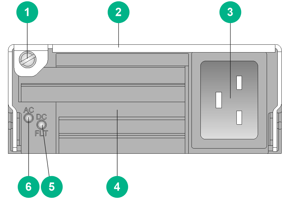
|
(1) Captive screw |
(2) Power supply handle |
|
(3) Power input receptacle |
(4) Air inlet vent |
|
(5) Power output status LED |
(6) Power input status LED |
LEDs
Table2-555 PSR1200B-12A/LSUM1AC1200 LED description
|
LED mark |
Status |
Description |
|
AC |
Steady green |
The power supply system is operating correctly. |
|
Off |
No power input. |
|
|
The input voltage is too low and the power supply has entered self-protection state. |
||
|
DC |
Steady green |
Power output of the power supply system is normal. |
|
Steady red |
Power output of the power supply system is abnormal. The power supply has an output short circuit, output overcurrent, output overvoltage, input undervoltage, or remote shutdown alarm and has entered self-protection state. |
|
|
Steady amber |
An overtemperature alarm was triggered and the power supply has entered self-protection state. |
Technical specifications
Table2-556 Technical specifications
|
Item |
Description |
|
Dimensions (H × W × D) |
41 × 102 × 410 mm (1.61 × 4.02 × 16.14 in) |
|
Weight |
2.27 kg (5.00 lb) |
|
Inputs |
1 |
|
Rated input voltage range |
100 VAC to 240 VAC @ 50 Hz or 60 Hz |
|
Input voltage range |
90 VAC to 290 VAC |
|
Maximum input current |
16 A |
|
Rated output voltage |
12 VDC |
|
Rated output current |
100 A |
|
Rated output power |
1200 W |
|
Front-level circuit breaker/fuse |
≥ 20 A |
|
Heat dissipation |
Built-in fans |
|
Power cable |
Standard C19 cable (3*1.5mm²) |
PSR1200B-12A1-F
View
Figure2-149 PSR1200B-12A1-F power supply view
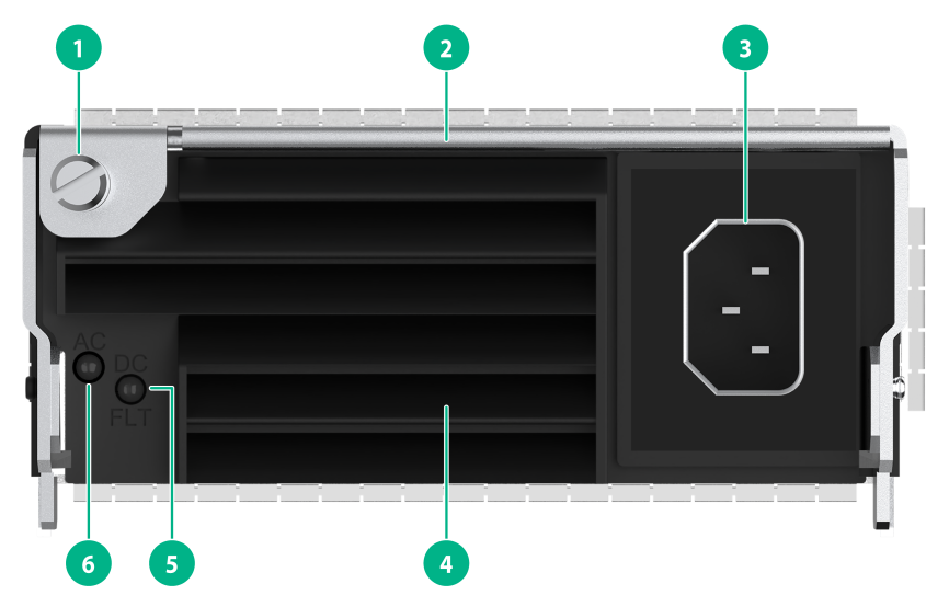
|
(1) Captive screw |
(2) Power supply handle |
|
(3) Power input receptacle |
(4) Air inlet vent |
|
(5) Power output status LED |
(6) Power input status LED |
LEDs
Table2-557 PSR1200B-12A1-F LED description
|
LED mark |
Status |
Description |
|
AC |
Steady green |
The power supply system is operating correctly. |
|
Off |
No power input. |
|
|
The input voltage is too low and the power supply has entered self-protection state. |
||
|
DC |
Steady green |
Power output of the power supply system is normal. |
|
Steady red |
Power output of the power supply system is abnormal. The power supply has an output short circuit, output overcurrent, output overvoltage, input undervoltage, or remote shutdown alarm and has entered self-protection state. |
|
|
Steady amber |
An overtemperature alarm was triggered and the power supply has entered self-protection state. |
Technical specifications
Table2-558 Technical specifications
|
Item |
Description |
|
Dimensions (H × W × D) |
41 × 102 × 410 mm (1.61 × 4.02 × 16.14 in) |
|
Weight |
2.27 kg (5.00 lb) |
|
Inputs |
1 |
|
Rated input voltage range |
200 VAC to 240 VAC @ 50 Hz or 60 Hz |
|
Input voltage range |
180 VAC to 264 VAC |
|
Maximum input current |
10 A |
|
Rated output voltage |
12 VDC |
|
Rated output current |
100 A |
|
Rated output power |
1200 W |
|
Front-level circuit breaker/fuse |
≥ 20 A |
|
Heat dissipation |
Built-in fans |
|
Power cable |
Standard C13 cable (3*1.0mm²) |
PSR2500-12A/LSUM1AC2500
View
Figure2-150 PSR2500-12A power supply view

|
(1) Captive screw |
(2) Power supply handle |
|
(3) Power input receptacle |
(4) Air inlet vent |
|
(5) Power output status LED |
(6) Power input status LED |
The views of the PSR2500-12A and LSUM1AC2500 power supplies are similar. This figure uses the PSR2500-12A as an example.
LEDs
Table2-559 PSR2500-12A/LSUM1AC2500 LED description
|
LED mark |
Status |
Description |
|
AC |
Steady green |
The power supply system is operating correctly. |
|
Off |
No power input. |
|
|
The input voltage is too low and the power supply has entered self-protection state. |
||
|
DC |
Steady green |
Power output of the power supply system is normal. |
|
Steady red |
Power output of the power supply system is abnormal. The power supply has an output short circuit, output overcurrent, output overvoltage, input undervoltage, or remote shutdown alarm and has entered self-protection state. |
|
|
Steady amber |
An overtemperature alarm was triggered and the power supply has entered self-protection state. |
Technical specifications
Table2-560 Technical specifications
|
Item |
Description |
|
Dimensions (H × W × D) |
41 × 102 × 410 mm (1.61 × 4.02 × 16.14 in) |
|
Weight |
2.50 kg (5.51 lb) |
|
Inputs |
1 |
|
Rated input voltage range |
· 100 VAC to 240 VAC @ 50 Hz or 60 Hz · 240 VDC |
|
Input voltage range |
· 90 VAC to 264 VAC · 190 VDC to 290 VDC |
|
Maximum input current |
16 A |
|
Rated output voltage |
12 VDC |
|
Rated output current |
· 100 A (100 VAC to 180 VAC input) · 208 A (180 VAC to 240 VAC or 240 VDC input) |
|
Rated output power |
· 1200 W (100 VAC to 180 VAC input) · 2500 W (180 VAC to 240 VAC or 240 VDC input) |
|
Front-level circuit breaker/fuse |
≥ 20 A |
|
Heat dissipation |
Built-in fans |
|
Power cable |
Standard C19 cable (3*1.5mm²) |
PSR2400-12D/LSUM1DC2400
View
Figure2-151 PSR2400-12D power supply view
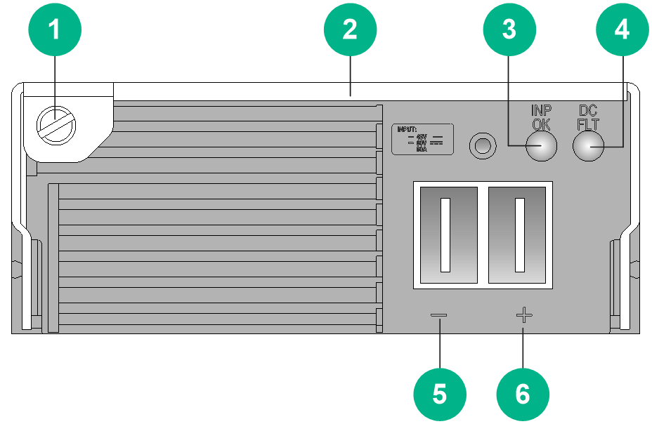
|
(1) Captive screw |
(2) Power supply handle |
|
(3) Power input status LED |
(4) Power output status LED |
|
(5) DC input negative terminal (–) |
(6) DC input positive terminal (+) |
The views of the PSR2400-12D and LSUM1DC2400 power supplies are similar. This figure uses the PSR2400-12D as an example.
LEDs
Table2-561 PSR2400-12D/LSUM1DC2400 LED description
|
LED mark |
Status |
Description |
|
INP OK |
Steady green |
The power supply system is operating correctly. |
|
Off |
No power input. |
|
|
The input voltage is too low and the power supply has entered self-protection state. |
||
|
DC/FLT |
Steady green |
Power output of the power supply system is normal. |
|
Steady red |
Power output of the power supply system is abnormal. The power supply has an output short circuit, output overcurrent, output overvoltage, input undervoltage, or remote shutdown alarm and has entered self-protection state. |
|
|
Steady amber |
An overtemperature alarm was triggered and the power supply has entered self-protection state. |
Technical specifications
Table2-562 Technical specifications
|
Item |
Description |
|
Dimensions (H × W × D) |
41 × 102 × 410 mm (1.61 × 4.02 × 16.14 in) |
|
Weight |
2.40 kg (5.29 lb) |
|
Inputs |
1 |
|
Rated input voltage range |
–48 VDC to –60 VDC |
|
Input voltage range |
–36 V to –72 V |
|
Maximum input current |
78 A |
|
Rated output voltage |
12 VDC |
|
Rated output current |
200 A |
|
Rated output power |
2400 W |
|
Front-level circuit breaker/fuse |
≥ 100 A |
|
Heat dissipation |
Built-in fans |
|
Power cable |
PWC01 2P cable |
PSR2400-D
View
Figure2-152 PSR2400-D power supply view
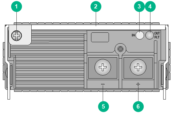
|
(1) Captive screw |
(2) Power supply handle |
|
(3) Power input status LED |
(4) Power output status LED |
|
(5) DC input negative terminal (–) |
(6) DC input positive terminal (+) |
LEDs
Table2-563 PSR2400-D LED description
|
LED mark |
Status |
Description |
|
INP OK |
Steady green |
The power supply system is operating correctly. |
|
Off |
No power input. |
|
|
The input voltage is too low and the power supply has entered self-protection state. |
||
|
DC/FLT |
Steady green |
Power output of the power supply system is normal. |
|
Steady red |
Power output of the power supply system is abnormal. The power supply has an output short circuit, output overcurrent, output overvoltage, input undervoltage, or remote shutdown alarm and has entered self-protection state. |
|
|
Steady amber |
An overtemperature alarm was triggered and the power supply has entered self-protection state. |
Technical specifications
Table2-564 Technical specifications
|
Item |
Description |
|
Dimensions (H × W × D) |
41 × 102 × 410 mm (1.61 × 4.02 × 16.14 in) |
|
Weight |
2.40 kg (5.29 lb) |
|
Inputs |
1 |
|
Rated input voltage range |
–48 VDC to –60 VDC |
|
Input voltage range |
–36 V to –72 V |
|
Maximum input current |
78 A |
|
Rated output voltage |
12 VDC |
|
Rated output current |
200 A |
|
Rated output power |
2400 W |
|
Front-level circuit breaker/fuse |
≥ 100 A |
|
Heat dissipation |
Built-in fans |
|
Power cable |
ST M5 cable |
PSR2500B-12AHD-F
View
Figure2-153 PSR2500B-12AHD-F power supply view
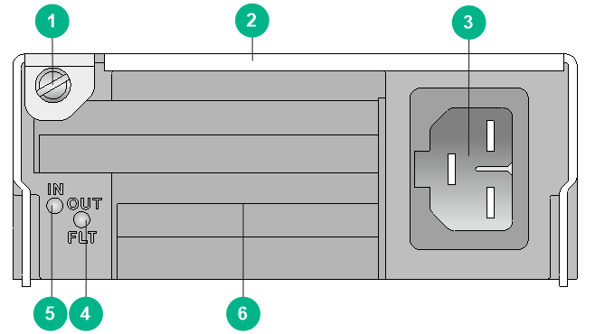
|
(1) Captive screw |
(2) Power supply handle |
|
(3) Power input receptacle |
(4) Power output status LED |
|
(5) Power input status LED |
(6) Air inlet vent |
LEDs
Table2-565 PSR2500B-12AHD-F LED description
|
LED mark |
Status |
Description |
|
IN |
Steady green |
The power supply system is operating correctly. |
|
Off |
No power input. |
|
|
The input voltage is too low and the power supply has entered self-protection state. |
||
|
OUT |
Steady green |
Power output of the power supply system is normal. |
|
Steady red |
Power output of the power supply system is abnormal. The power supply has an output short circuit, output overcurrent, output overvoltage, input undervoltage, or remote shutdown alarm and has entered self-protection state. |
|
|
Steady amber |
An overtemperature alarm was triggered and the power supply has entered self-protection state. |
Technical specifications
Table2-566 Technical specifications
|
Item |
Description |
|
Dimensions (H × W × D) |
41 × 102 × 410 mm (1.61 × 4.02 × 16.14 in) |
|
Weight |
2.75 kg (6.06 lb) |
|
Inputs |
1 |
|
Rated input voltage range |
· 100 VAC to 240 VAC @ 50 Hz or 60 Hz · 240 VDC to 380 VDC |
|
Input voltage range |
· 90 VAC to 290 VAC · 180 VDC to 400 VDC |
|
Maximum input current |
16 A |
|
Rated output voltage |
12 VDC |
|
Rated output current |
· 100 A (90 VAC to 180 VAC input) · 208 A (180 VAC to 290 VAC or 180 VDC to 400 VDC input) |
|
Rated output power |
· 1200 W (90 VAC to 180 VAC input) · 2500 W (180 VAC to 290 VAC or 180 VDC to 400 VDC input) |
|
Front-level circuit breaker/fuse |
≥ 20 A |
|
Heat dissipation |
Built-in fans |
|
Power cable |
Standard HVDCB cable (3*1.5mm²) |
PSR1600B-12A-B
View
Figure2-154 PSR1600B-12A-B power supply view
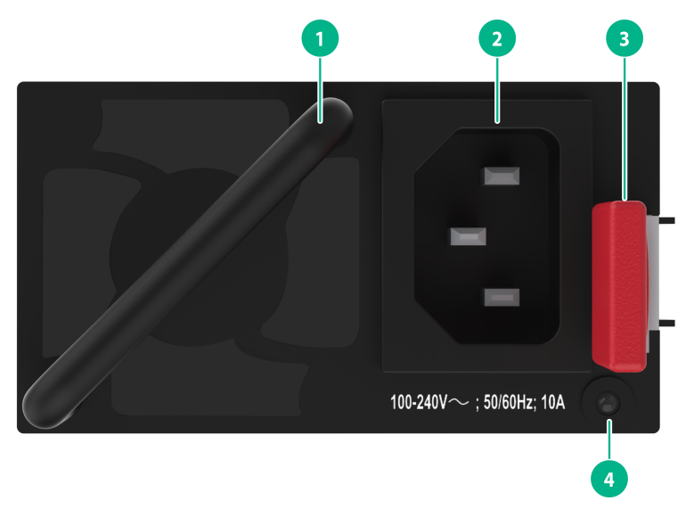
|
(1) Power supply handle |
(2) Power input receptacle |
|
(3) Latch |
(4) Power status LED |
LEDs
Table2-567 PSR1600B-12A-B LED description
|
LED status |
Description |
|
Steady green |
The power supply system is operating correctly. |
|
Flashing green (once per two seconds) |
The power supply has correct power input and is in standby state with 12 V standby output and without 12 V main output. |
|
Flashing green (twice per second) |
The power supply is upgrading software. |
|
Flashing green (once per three seconds) |
The power supply has entered cold redundancy state. |
|
Steady yellow |
The power supply is faulty and does not have power output. |
|
Flashing yellow (once per second) |
· The power supply is operating correctly, but an alarm has occurred (such as input undervoltage, output overcurrent, and overtemperature). · The power supply does not have power input, but the backup power supplies have correct power input. |
|
Off |
No power input. |
Technical specifications
Table2-568 Technical specifications
|
Item |
Description |
|
Dimensions (H × W × D) |
40.2 × 73.5 × 225 mm (1.58 × 2.89 × 8.86 in) |
|
Weight |
1.85 kg (4.08 lb) |
|
Inputs |
1 |
|
Rated input voltage range |
· 100 VAC to 240 VAC @ 50 Hz or 60 Hz · 240 VDC |
|
Input voltage range |
· 90 VAC to 305 VAC · 180 VDC to 320 VDC |
|
Maximum input current |
10 A |
|
Rated output voltage |
12 VDC |
|
Rated output current |
· 65.5 A (100 to 180 VAC) · 131 A (180 to 240 VAC or 240 VDC) |
|
Rated output power |
· 800 W (100 to 180 VAC) · 1600 W (180 to 240 VAC or 240 VDC) |
|
Front-level circuit breaker/fuse |
≥ 32 A |
|
Heat dissipation |
Built-in fans |
|
Power cable |
Standard C13 cable (3*1.0mm²) |
PSR2000-12D-B
View
Figure2-155 PSR2000-12D-B power supply view
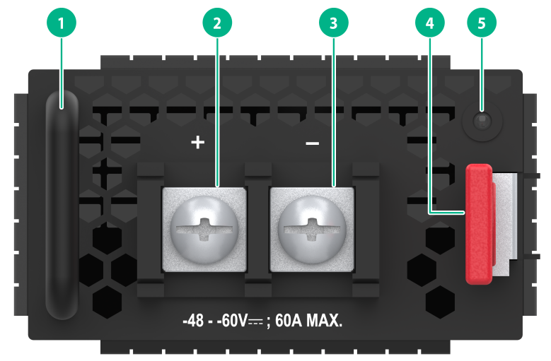
|
(1) Power supply handle |
(2) DC input negative terminal (+) |
|
(3) DC input negative terminal (–) |
(4) Latch |
|
(5) Power status LED |
|
LEDs
Table2-569 PSR2000-12D-B LED description
|
LED status |
Description |
|
Steady green |
The power supply system is operating correctly. |
|
Flashing green (once per second) |
The power supply is upgrading software. |
|
Flashing green (once per two seconds) |
The power supply has correct power input and is in standby state with 12 V standby output and without 12 V main output. |
|
Steady yellow |
The power supply is faulty and does not have power output. |
|
Flashing yellow (once per second) |
The power supply does not have power input, but the backup power supplies have correct power input. |
|
Flashing yellow (once per two seconds) |
The power supply is operating correctly, but an alarm has occurred (such as input undervoltage, output overcurrent, and overtemperature). |
|
Off |
No power input. |
Technical specifications
Table2-570 Technical specifications
|
Item |
Description |
|
Dimensions (H × W × D) |
40.2 × 73.5 × 225 mm (1.58 × 2.89 × 8.86 in) |
|
Weight |
1.50 kg (3.31 lb) |
|
Inputs |
1 |
|
Rated input voltage range |
–48 VDC |
|
Input voltage range |
–40 VDC to –72 VDC |
|
Maximum input current |
60 A |
|
Rated output voltage |
12 VDC |
|
Rated output current |
167 A |
|
Rated output power |
2000 W |
|
Front-level circuit breaker/fuse |
≥ 100 A |
|
Heat dissipation |
Built-in fans |
|
Power cable |
External DC power cords (6 AWG) |
Configuration restrictions and guidelines
· As a best practice, make sure the rated current of a single circuit breaker is not less than 1.2 times the maximum input current of the power supply.
· You can select a certain number of power supplies according to the power supply conditions at the installation site and actual power consumption of your router. Make sure the total maximum output power of the installed power supplies is greater than the system power consumption. As a best practice, reserve 20% of the maximum output power.
· Do not install power supplies of different models on the same router.
· When the temperature of a power supply exceeds the upper limit or drops below the lower limit, the power supply shuts down automatically. When the temperature falls into the normal range, the power supply starts up automatically.
Compatibility information
Table2-571 Compatibility matrix between power supplies and routers (1)
|
Power supply module |
CR16006-F |
CR16010-F(one fan tray)/CR16010-F (dual fan trays) |
CR16010H-F (with four fabric modules), CR16010H-F (with five fabric modules) |
CR16010H-FA |
|
PSR1200B-12A |
● |
● |
● |
● |
|
PSR1200B-12A1-F |
● |
● |
● |
● |
|
LSUM1AC2500 |
● |
● |
● |
● |
|
PSR2500-12A |
● |
● |
● |
● |
|
LSUM1DC2400 |
● |
● |
● |
● |
|
PSR2400-12D |
● |
● |
● |
● |
|
PSR2400-D |
● |
● |
● |
● |
|
PSR2500B-12AHD-F |
● |
● |
● |
● |
|
PSR1600B-12A-B |
— |
— |
— |
— |
|
PSR2000-12D-B |
— |
— |
— |
— |
Table2-572 Compatibility matrix between power supplies and routers (2)
|
Power supply module |
CR16014-F |
CR16018-F (with four fabric modules), CR16018-F (with five fabric modules) |
CR16018-FA |
CR16003E-F, CR16005E-F, CR16010E-F |
|
PSR1200B-12A |
● |
● |
● |
— |
|
PSR1200B-12A1-F |
● |
● |
● |
— |
|
LSUM1AC2500 |
● |
● |
● |
— |
|
PSR2500-12A |
● |
● |
● |
— |
|
LSUM1DC2400 |
● |
● |
● |
— |
|
PSR2400-12D |
● |
● |
● |
— |
|
PSR2400-D |
● |
● |
● |
— |
|
PSR2500B-12AHD-F |
● |
● |
● |
— |
|
PSR1600B-12A-B |
— |
— |
— |
● |
|
PSR2000-12D-B |
— |
— |
— |
● |
|
|
NOTE: · "●" indicates that the power supply is compatible with the chassis. · "—" indicates that the power supply is not compatible with the chassis. |
Fan trays
The router came with fan trays installed. To replace a fan tray, make sure the new fan tray is compatible with the router.
CR16006-F fan tray
View
Figure2-156 CR16006-F fan tray view

|
(1) Captive screw |
(2) Status LED |
|
(3) Fan tray handle |
(4) Fan tray handle pivot |
|
(5) Fan |
|
LEDs
Table2-573 Fan tray LED description
|
LED status |
Description |
|
|
OK |
FAIL |
|
|
Steady on |
Off |
The fan tray is operating correctly. |
|
Off |
Steady on |
The fan tray is faulty. |
|
Off |
Off |
The fan tray is not powered on. |
Technical specifications
Table2-574 Technical specifications
|
Item |
Description |
|
Dimensions (H × W × D) |
106 × 255 × 643 mm (4.17 × 10.04 × 25.32 in) |
|
Weight |
4.70 kg (10.36 lb) |
|
Maximum power consumption |
240 W |
|
Power consumption (with typical configuration) |
190 W |
|
Minimum power consumption |
12 W |
|
Number of fans |
8 |
|
Fan diameter |
92 mm (3.62 in) |
|
Max fan speed |
6000 RPM |
|
Maximum air flow rate |
960 CFM (27.18 m3/min) |
CR16010-F (one fan tray) fan tray
View
Figure2-157 CR16010-F (one fan tray) fan tray view
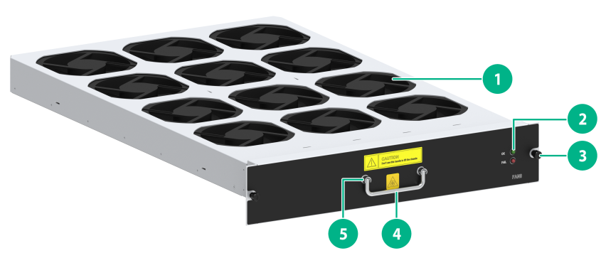
|
(1) Fan |
(2) Status LED |
|
(3) Captive screw |
(4) Fan tray handle |
|
(5) Fan tray handle pivot |
|
LEDs
Table2-575 Fan tray LED description
|
LED status |
Description |
|
|
OK |
FAIL |
|
|
Steady on |
Off |
The fan tray is operating correctly. |
|
Off |
Steady on |
The fan tray is faulty. |
|
Off |
Off |
The fan tray is not powered on. |
Technical specifications
Table2-576 Technical specifications
|
Item |
Description |
|
Dimensions (H × W × D) |
80 × 440 × 654 mm (3.15 × 17.32 × 25.75 in) |
|
Weight |
8.30 kg (18.30 lb) |
|
Maximum power consumption |
300 W |
|
Power consumption (with typical configuration) |
260 W |
|
Minimum power consumption |
13 W |
|
Number of fans |
12 |
|
Fan diameter |
120 mm (4.72 in) |
|
Max fan speed |
5200 RPM |
|
Maximum air flow rate |
1152 CFM (32.62 m3/min) |
CR16010-F (dual fan trays) fan tray
View
Figure2-158 CR16010-F (dual fan trays) fan tray view
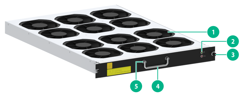
|
(1) Fan |
(2) Status LED |
|
(3) Captive screw |
(4) Fan tray handle |
|
(5) Fan tray handle pivot |
|
LEDs
Table2-577 Fan tray LED description
|
LED status |
Description |
|
|
OK |
FAIL |
|
|
Steady on |
Off |
The fan tray is operating correctly. |
|
Off |
Steady on |
The fan tray is faulty. |
|
Off |
Off |
The fan tray is not powered on. |
Technical specifications
The CR16010-F (dual fan trays) has two fan trays, which are the same in technical specifications. Table2-578 describes the technical specifications of a single CR16010-F (dual fan trays) fan tray.
Table2-578 Technical specifications
|
Item |
Description |
|
Dimensions (H × W × D) |
49 × 440 × 654 mm (1.93 × 17.32 × 25.75 in) |
|
Weight |
7.40 kg (16.31 lb) |
|
Maximum power consumption |
320 W |
|
Power consumption (with typical configuration) |
63 W |
|
Minimum power consumption |
18 W |
|
Number of fans |
12 |
|
Fan diameter |
120 mm (4.72 in) |
|
Max fan speed |
5200 RPM |
|
Maximum air flow rate |
1152 CFM (32.62 m3/min) |
CR16010H-F/CR16010H-FA/CR16018-F/CR16018-FA fan trays
This section applies to the CR16010H-F (with five fabric modules), CR16010H-F (with four fabric modules), CR16010H-FA, CR16018-F (with five fabric modules), CR16018-F (with four fabric modules), and CR16018-FA routers.
View
Figure2-159 CR16010H-F (with five fabric modules) fan tray view
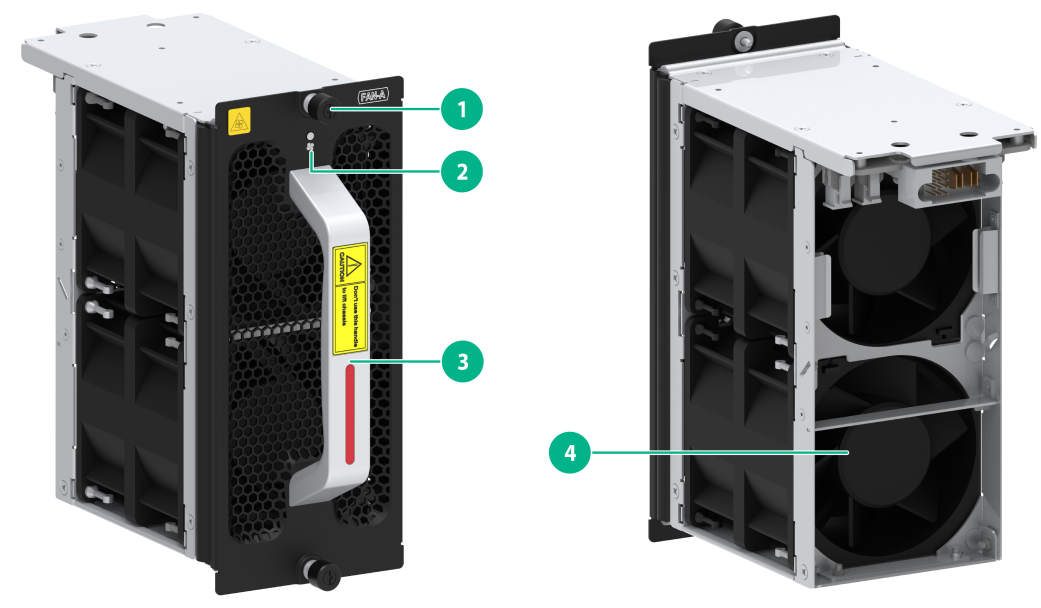
|
(1) Captive screw |
(2) Status LED |
|
(3) Fan tray handle |
(4) Fan |
The views of the CR16010H-F (with five fabric modules), CR16010H-F (with four fabric modules), CR16010H-FA, CR16018-F (with five fabric modules), CR16018-F (with four fabric modules), and CR16018-FA fan trays are similar. This figure uses the CR16010H-F (with five fabric modules) fan tray as an example.
LEDs
Table2-579 Fan tray LED description
|
RUN LED status |
Description |
|
Steady green |
The fan tray is operating correctly. |
|
Steady red |
One or more fans in the fan tray have failed or the fan tray is not in position. |
|
Off |
The fan tray is not powered on. |
Technical specifications
The CR16010H-F (with five fabric modules), CR16010H-F (with four fabric modules), and CR16010H-FA routers each have eight fan trays. The CR16018-F (with five fabric modules), CR16018-F (with four fabric modules), and CR16018-FA routers each have 15 fan trays. The fan trays have the same technical specifications. Table2-580 describes the technical specifications of a single CR16010H-F (with five fabric modules) fan tray.
Table2-580 Technical specifications
|
Item |
Description |
|
Dimensions (H × W × D) |
191 × 81 × 159 mm (7.52 × 3.19 × 6.26 in) |
|
Weight |
1.35 kg (2.98 lb) |
|
Maximum power consumption |
143 W |
|
Power consumption (with typical configuration) |
114 W |
|
Minimum power consumption |
18 W |
|
Number of fans |
2 |
|
Fan diameter |
80 mm (3.15 in) |
|
Max fan speed |
12800 RPM |
|
Maximum air flow rate |
350 CFM (9.91 m3/min) |
CR16014-F fan tray
View
Figure2-160 CR16014-F fan tray view
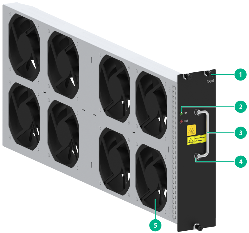
|
(1) Captive screw |
(2) Status LED |
|
(3) Fan tray handle |
(4) Fan tray handle pivot |
|
(5) Fan |
|
LEDs
Table2-581 Fan tray LED description
|
LED status |
Description |
|
|
OK |
FAIL |
|
|
Steady on |
Off |
The fan tray is operating correctly. |
|
Off |
Steady on |
The fan tray is faulty. |
|
Off |
Off |
The fan tray is not powered on. |
Technical specifications
Table2-582 Technical specifications
|
Item |
Description |
|
Dimensions (H × W × D) |
84 × 301 × 646 mm (3.31 × 11.85 × 25.43 in) |
|
Weight |
· Upper fan tray: 4.49 kg (9.90 lb) · Lower fan tray: 3.61 kg (7.96 lb) |
|
Maximum power consumption |
· Upper fan tray: 190 W · Lower fan tray: 110 W |
|
Power consumption (with typical configuration) |
· Upper fan tray: 160 W · Lower fan tray: 100 W |
|
Minimum power consumption |
· Upper fan tray: 9 W · Lower fan tray: 7 W |
|
Number of fans |
· Upper fan tray: 8 · Lower fan tray: 4 |
|
Fan diameter |
120 mm (4.72 in) |
|
Max fan speed |
5200 RPM |
|
Maximum air flow rate |
· Upper fan tray: 1040 CFM (29.45 m3/min) · Lower fan tray: 720 CFM (20.39 m3/min) |
CR16003E-F fan tray
View
Figure2-161 CR16003E-F fan tray view

|
(1) Fan tray handle pivot |
(2) Status LED |
|
(3) Fan tray handle |
(4) Captive screw |
|
(5) Fan |
|
LEDs
Table2-583 Fan tray LED description
|
RUN LED status |
Description |
|
Steady green |
The fan tray is operating correctly. |
|
Steady red |
One or more fans in the fan tray have failed or the fan tray is not in position. |
|
Off |
The fan tray is not powered on. |
Technical specifications
The CR16003E-F has two fan trays, which are the same in technical specifications. Table2-584 describes the technical specifications of a single CR16003E-F fan tray.
Table2-584 Technical specifications
|
Item |
Description |
|
Dimensions (H × W × D) |
167 × 133 × 117 mm (6.57 × 5.24 × 4.61 in) |
|
Weight |
1.30 kg (2.87 lb) |
|
Maximum power consumption |
95 W |
|
Power consumption (with typical configuration) |
18 W |
|
Minimum power consumption |
4 W |
|
Number of fans |
2 |
|
Fan diameter |
80 mm (3.15 in) |
|
Max fan speed |
13800 RPM |
|
Maximum air flow rate |
135.15 CFM (3.83 m3/min) |
CR16005E-F fan tray
View
Figure2-162 CR16005E-F fan tray view
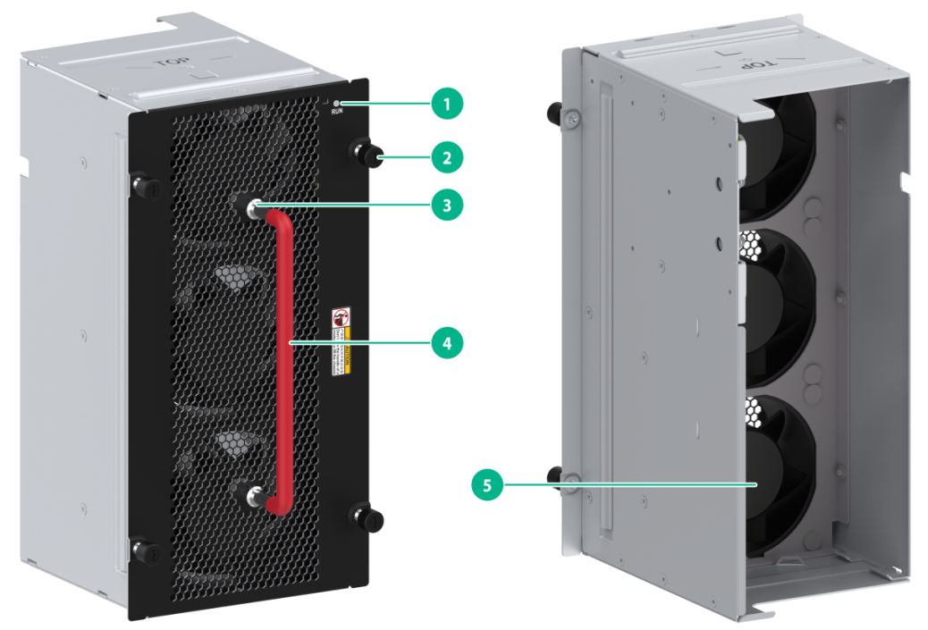
|
(1) Status LED |
(2) Captive screw |
|
(3) Fan tray handle pivot |
(4) Fan tray handle |
|
(5) Fan |
|
LEDs
Table2-585 Fan tray LED description
|
RUN LED status |
Description |
|
Steady green |
The fan tray is operating correctly. |
|
Steady red |
One or more fans in the fan tray have failed or the fan tray is not in position. |
|
Off |
The fan tray is not powered on. |
Technical specifications
The CR16005E-F has two fan trays, which are the same in technical specifications. Table2-586 describes the technical specifications of a single CR16005E-F fan tray.
Table2-586 Technical specifications
|
Item |
Description |
|
Dimensions (H × W × D) |
247.5 × 111 × 105 mm (9.74 × 4.37 × 4.13 in) |
|
Weight |
2.05 kg (4.52 lb) |
|
Maximum power consumption |
142 W |
|
Power consumption (with typical configuration) |
102 W |
|
Minimum power consumption |
7 W |
|
Number of fans |
3 |
|
Fan diameter |
80 mm (3.15 in) |
|
Max fan speed |
15200 RPM |
|
Maximum air flow rate |
390 CFM (11.04 m3/min) |
CR16010E-F fan tray
View
Figure2-163 CR16010E-F fan tray view
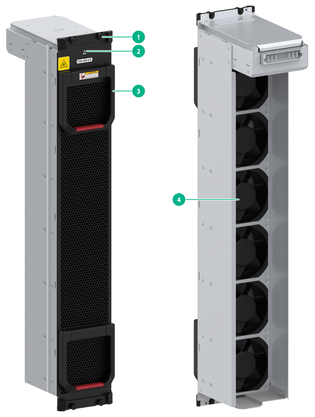
|
(1) Captive screw |
(2) Status LED |
|
(3) Fan tray handle |
(4) Fan |
LEDs
Table2-587 Fan tray LED description
|
RUN LED status |
Description |
|
Steady green |
The fan tray is operating correctly. |
|
Steady red |
One or more fans in the fan tray have failed or the fan tray is not in position. |
|
Off |
The fan tray is not powered on. |
Technical specifications
The CR16010E-F came with two fan trays installed. It supports a maximum of three fan trays, which are the same in technical specifications. Table2-588 describes the technical specifications of a single CR16010E-F fan tray.
Table2-588 Technical specifications
|
Item |
Description |
|
Dimensions (H × W × D) |
571.5 × 93.2 × 162 mm (22.5 × 3.67 × 6.38 in) |
|
Weight |
4.25 kg (9.37 lb) |
|
Maximum power consumption |
284 W |
|
Power consumption (with typical configuration) |
204 W |
|
Minimum power consumption |
14 W |
|
Number of fans |
6 |
|
Fan diameter |
80 mm (3.15 in) |
|
Max fan speed |
15200 RPM |
|
Maximum air flow rate |
780 CFM (22.09 m3/min) |
Air filters
|
|
CAUTION: Clean air filters periodically (once or more times every three months) to guarantee adequate ventilation and to avoid overtemperature. |
To prevent dusts from entering the chassis, you can configure air filters for the router as needed and install them at the air intakes.
H3C CR16000-F air filters include the CR16006-F air filter, CR16010-F air filter, and CR16014-F air filter. Order air filters compatible with your router.
Slide rails
Before rack-mounting the router, install slide rails on the rack.
LSXM1BSR
Views
Figure2-164 LSXM1BSR slide rail view
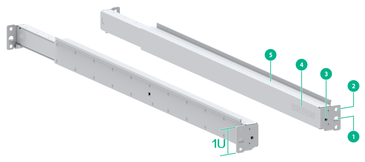
|
(1) Positioning tongue |
(2) Slide rail installation hole |
|
(3) Front plate installation hole |
(4) Sign |
|
(5) Guide rail |
|
Figure2-165 Front plate

|
(1) Installation hole |
Technical specifications
Table2-589 Technical specifications
|
Item |
Description |
|
Maximum loading capacity |
650 kg (1432.98 lb) |
|
Adjustment range |
630 to 900 mm (24.80 to 35.43 in) |
|
Occupied rack space |
1 RU |
LSTM1KSGD0
Views
Figure2-166 LSTM1KSGD0 slide rail view
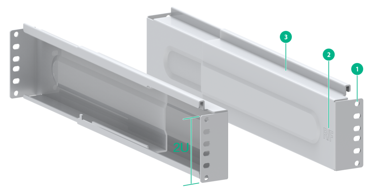
|
(1) Installation hole |
(2) Sign |
|
(3) Guide rail |
|
Technical specifications
Table2-590 Technical specifications
|
Item |
Description |
|
Maximum loading capacity |
280 kg (617.28 lb) |
|
Adjustment range |
300 to 500 mm (11.81 to 19.69 in) |
|
Occupied rack space |
2 RUs |
LSTM2KSGD0
Views
Figure2-167 LSTM2KSGD0 slide rail view
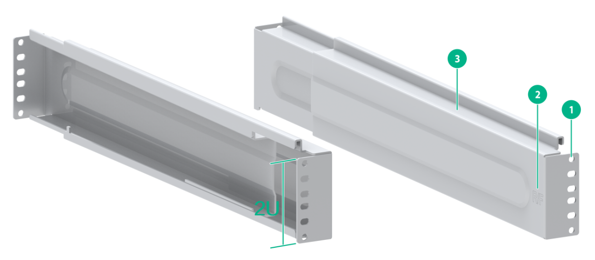
|
(1) Installation hole |
(2) Sign |
|
(3) Guide rail |
|
Technical specifications
Table2-591 Technical specifications
|
Item |
Description |
|
Maximum loading capacity |
400 kg (881.83 lb) |
|
Adjustment range |
500 to 800 mm (19.69 to 31.50 in) |
|
Occupied rack space |
2 RUs |
RL-1U-A
Views
Figure2-168 RL-1U-A slide rail view
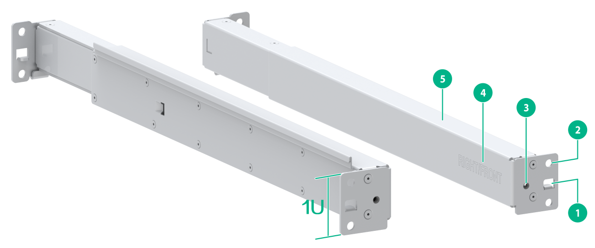
|
(1) Positioning tongue |
(2) Slide rail installation hole |
|
(3) Front plate installation hole |
(4) Sign |
|
(5) Guide rail |
|
Figure2-169 Front plate
|
(1) Installation hole |
Technical specifications
Table2-592 Technical specifications
|
Item |
Description |
|
Maximum loading capacity |
200 kg (440.92 lb) |
|
Adjustment range |
380 to 630 mm (14.96 to 24.80 in) |
|
Occupied rack space |
1 RU |
Configuration restrictions and guidelines
· Select slide rails for the router based on the chassis weight.
· To rack-mount a CR16018-F (with four fabric modules), CR16018-F (with five fabric modules), or CR16018-FA router, reserve a 2 RU space between the router (including slide rails) and the rack bottom.
Compatibility information
Table2-593 Chassis weights and applicable slide rails
|
Model |
Chassis weight (fully configured) |
Applicable slide rails |
|
CR16006-F |
76 kg (167.55 lb) |
LSXM1BSR LSTM1KSGD0 LSTM2KSGD0 |
|
CR16010-F (one fan tray) |
120 kg (264.55 lb) |
LSXM1BSR LSTM1KSGD0 LSTM2KSGD0 |
|
CR16010-F (dual fan trays) |
170 kg (374.78 lb) |
LSXM1BSR LSTM1KSGD0 LSTM2KSGD0 |
|
SR8812-F |
95 kg (209.44 lb) |
LSXM1BSR LSTM1KSGD0 LSTM2KSGD0 |
|
CR16010H-F (with four fabric modules), CR16010H-F (with five fabric modules), CR16010H-FA |
245 kg (540.12 lb) |
LSXM1BSR LSTM1KSGD0 LSTM2KSGD0 |
|
CR16014-F |
174 kg (383.60 lb) |
LSXM1BSR LSTM1KSGD0 LSTM2KSGD0 |
|
CR16018-F (with four fabric modules), CR16018-F (with five fabric modules), CR16018-FA |
440 kg (970.02 lb) |
LSXM1BSR LSTM2KSGD0 |
|
CR16003E-F |
62.7 kg (138.23 lb) |
LSXM1BSR RL-1U-A |
|
CR16005E-F |
100 kg (220.46 lb) |
LSXM1BSR RL-1U-A |
|
CR16010E-F |
200 kg (440.92 lb) |
LSXM1BSR RL-1U-A |
DC power cords
DC power cords are used for connecting the DC power supplies of an SR8800-X router to the external DC power supply system.
Table2-594 DC power cord specifications
|
DC power cord |
Cable length |
Description |
|
0404A0E1 |
3 m (9.84 ft) |
Used for connecting the LSUM1DC2400/PSR2400-12D power supply |
|
0404A0H8 |
3 m (9.84 ft) |
|
|
0404A0E2 |
15 m (49.21 ft) |
|
|
0404A0H9 |
15 m (49.21 ft) |
|
|
0404A1BE |
20 m (65.62 ft) |
|
|
0404A1BF |
20 m (65.62 ft) |
|
|
0404A0J5 |
30 m (98.43 ft) |
|
|
0404A1BD |
40 m (131.23 ft) |
|
|
0404A1M7 |
10 m (32.81 ft) |
Used for connecting the PSR2400-D power supply |
|
0404A1M6 |
15 m (49.21 ft) |
|
|
0404A1M5 |
20 m (65.62 ft) |
|
|
0404A1MD |
30 m (98.43 ft) |
|
|
0404A1X2 |
3 m (9.84 ft) |
Used for connecting the PSR2000-12D-B power supply |
|
0404A1X3 |
15 m (49.21 ft) |
AC power cords
AC power cords are used for connecting the AC power supplies of a CR16000-F router to the external AC power supply system.
To select an AC power cord for an AC power supply, consider the following items:
· Power capacity of the power supply.
· Current-carrying capacity of the power cord.
· Region-and country-specific plug type.
The AC power supplies available for the router require a 16A or 10A AC power cord. Table2-595 and Table2-596 describe the region-and country-specific plug types for 10A and 16A AC power cords, respectively.
Table2-595 10A AC power cords used in different countries or regions
|
1 |
Plug type |
Code (Length) |
Countries or regions where the type of power cords conforms to local safety regulations and can be used legally |
Other countries or regions using this type of power cords |
Countries or regions seldom using this type of power cords |
||||
|
I type |
04041104: 3 m (9.8 ft) |
Mainland China |
N/A |
N/A |
|||||
|
Plug outline |
Power cord outline |
Connector outline |
|||||||
|
|
|
|
|||||||
|
2 |
Plug type |
Code (Length) |
Countries or regions where the type of power cords conforms to local safety regulations and can be used legally |
Other countries or regions using this type of power cords |
Countries or regions seldom using this type of power cords |
||||
|
B type |
04020728: 3 m (9.8 ft) |
Canada and U.S.A |
Mexico, Argentina, Brazil, Columbia, Venezuela, Thailand, Peru, Philippine, and A6 countries or regions |
N/A |
|||||
|
Plug outline |
Power cord outline |
Connector outline |
|||||||
|
|
|
|
|||||||
|
3 |
Plug type |
Code (Length) |
Countries or regions where the type of power cords conforms to local safety regulations and can be used legally |
Other countries or regions using this type of power cords |
Countries or regions seldom using this type of power cords |
||||
|
F type |
04041056: 3 m (9.8 ft) |
Holland, Denmark, Sweden, Finland, Norway, Germany, France, Austria, Belgium, and Italy |
Indonesia, Türkiye, Russia, and CIS |
N/A |
|||||
|
Plug outline |
Power cord outline |
Connector outline |
|||||||
|
|
|
|
|||||||
|
4 |
Plug type |
Code (Length) |
Countries or regions where the type of power cords conforms to local safety regulations and can be used legally |
Other countries or regions using this type of power cords |
Countries or regions seldom using this type of power cords |
||||
|
G type |
04040890: 3 m (9.8 ft) |
United Kingdom |
Malaysia, Hong Kong, and Egypt |
N/A |
|||||
|
Connector outline |
Power cord outline |
Connector outline |
|||||||
|
|
|
|
|||||||
|
5 |
Plug type |
Code (Length) |
Countries or regions where the type of power cords conforms to local safety regulations and can be used legally |
Other countries or regions using this type of power cords |
Countries or regions seldom using this type of power cords |
||||
|
B type |
04040887: 3 m (9.8 ft) |
Japan |
N/A |
N/A |
|||||
|
Plug outline |
Power cord outline |
Connector outline |
|||||||
|
|
|
|
|||||||
|
6 |
Plug type |
Code (Length) |
Countries or regions where the type of power cords conforms to local safety regulations and can be used legally |
Other countries or regions using this type of power cords |
Countries or regions seldom using this type of power cords |
||||
|
I type |
04040888: 3 m (9.8 ft) |
Australia |
N/A |
N/A |
|||||
|
Plug outline |
Power cord outline |
Connector outline |
|||||||
|
|
|
|
|||||||
|
7 |
Plug type |
Code (Length) |
Countries or regions where the type of power cords conforms to local safety regulations and can be used legally |
Other countries or regions using this type of power cords |
Countries or regions seldom using this type of power cords |
||||
|
J type |
04041119: 3 m (9.8 ft) |
Switzerland |
N/A |
N/A |
|||||
|
Plug outline |
Power cord outline |
Connector outline |
|||||||
|
|
|
|
|||||||
|
8 |
Plug type |
Code (Length) |
Countries or regions where the type of power cords conforms to local safety regulations and can be used legally |
Other countries or regions using this type of power cords |
Countries or regions seldom using this type of power cords |
||||
|
L type |
04041120: 3 m (9.8 ft) |
Italy |
N/A |
N/A |
|||||
|
Plug outline |
Power cord outline |
Connector outline |
|||||||
|
|
|
|
|||||||
|
9 |
Plug type |
Code (Length) |
Countries or regions where the type of power cords conforms to local safety regulations and can be used legally |
Other countries or regions using this type of power cords |
Countries or regions seldom using this type of power cords |
||||
|
D type |
0404A0Q0: 3 m (9.8 ft) |
India |
N/A |
N/A |
|||||
|
Plug outline |
Power cord outline |
Connector outline |
|||||||
|
|
|
|
|||||||
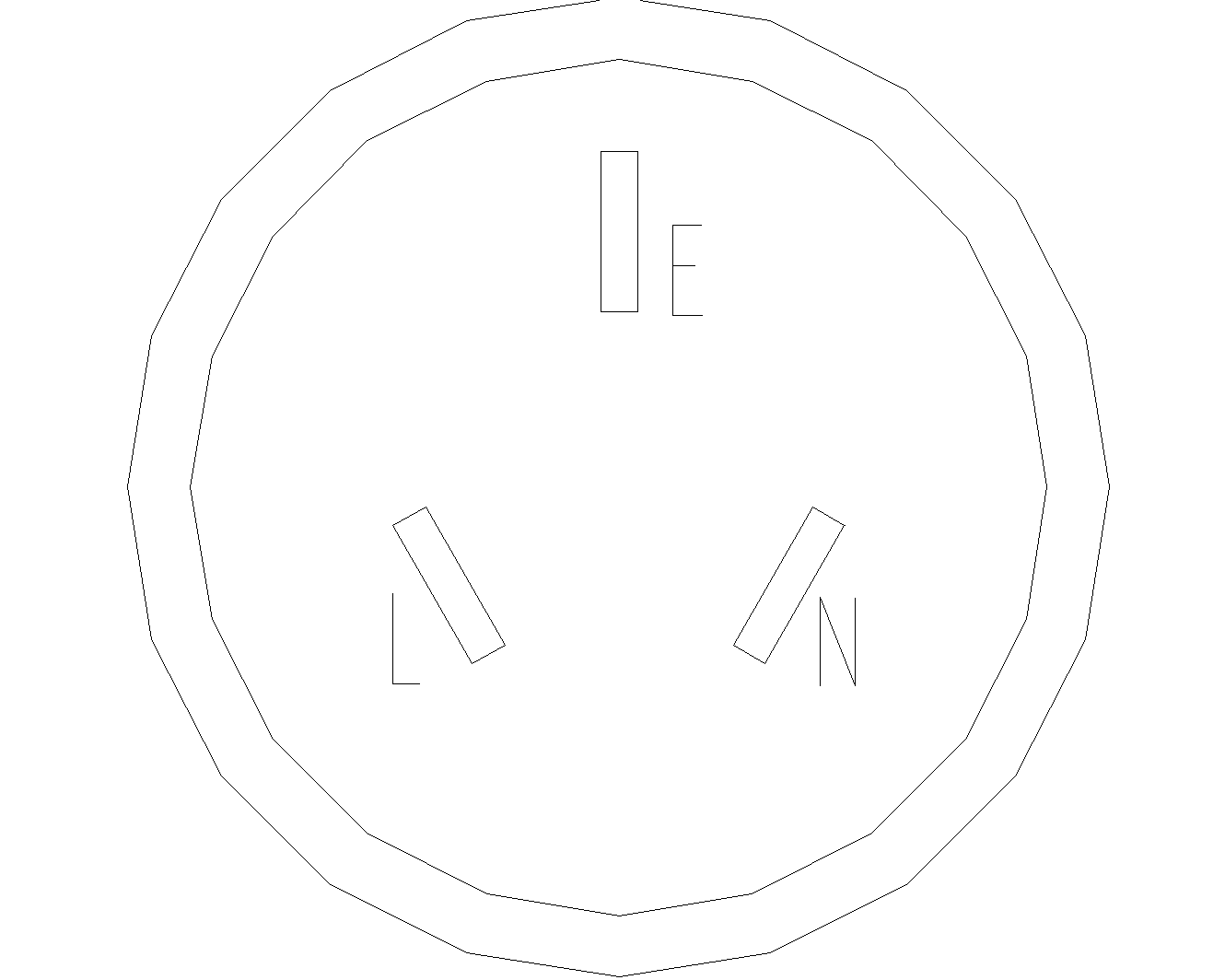
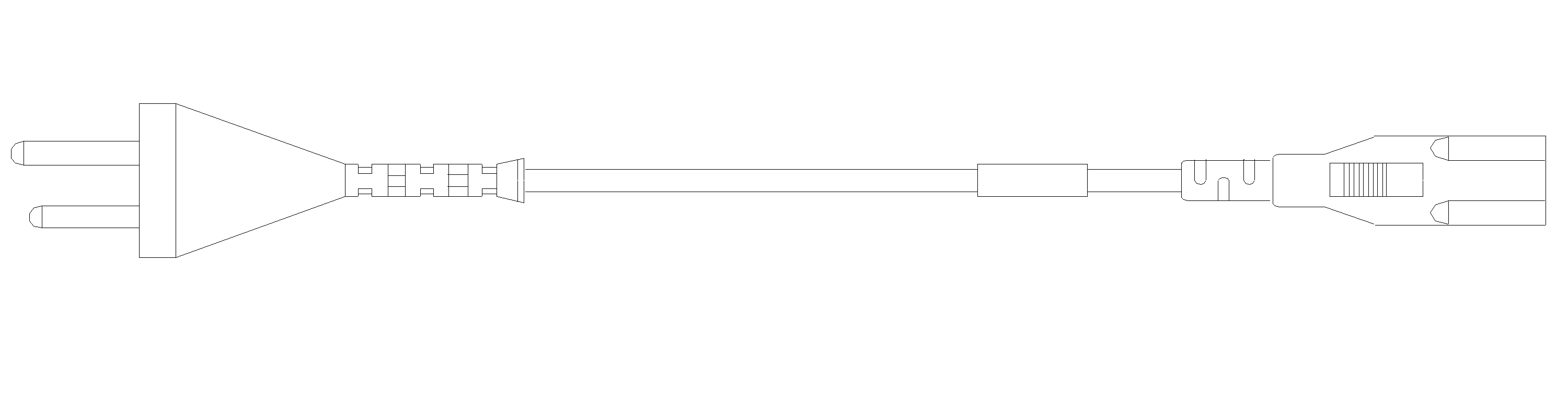
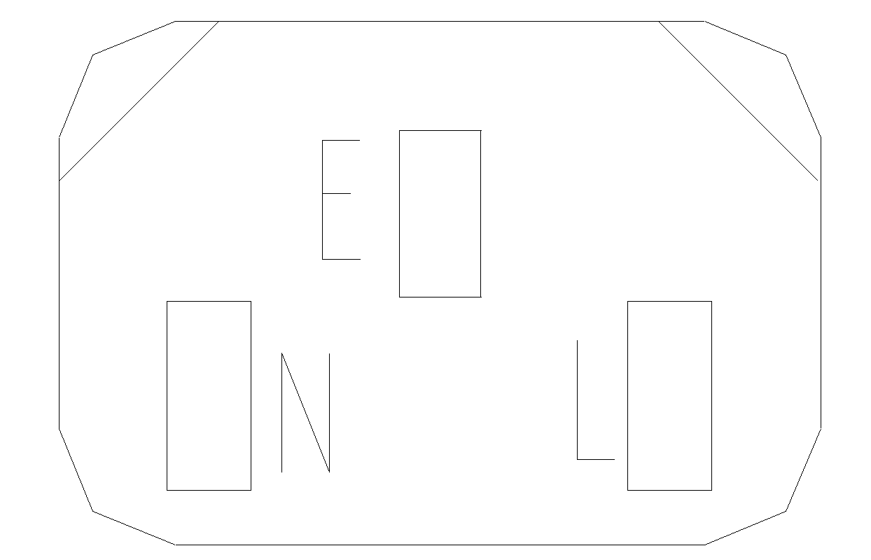


Table2-596 16A AC power cords used in different countries or regions
|
1 |
Plug type |
Code (Length) |
Countries or regions where the type of power cords conforms to local safety regulations and can be used legally |
Other countries or regions using this type of power cords |
Countries or regions seldom using this type of power cords |
|||||
|
I type |
04043396: 3 m (9.8 ft) |
Mainland China |
N/A |
N/A |
||||||
|
Plug outline |
Power cord outline |
Connector outline |
||||||||
|
|
|
|
||||||||
|
2 |
Plug type |
Code (Length) |
Countries or regions where the type of power cords conforms to local safety regulations and can be used legally |
Other countries or regions using this type of power cords |
Countries or regions seldom using this type of power cords |
|||||
|
C20 type |
0404A0C2: 3 m (9.8 ft) |
Mainland China |
N/A |
N/A |
||||||
|
Plug outline |
Power cord outline |
Connector outline |
||||||||
|
|
|
|
||||||||
|
3 |
Plug type |
Code (Length) |
Countries or regions where the type of power cords conforms to local safety regulations and can be used legally |
Other countries or regions using this type of power cords |
Countries or regions seldom using this type of power cords |
|||||
|
B type |
0404A063: 3 m (9.8 ft) |
Canada and U.S.A |
Mexico, Argentina, Brazil, Columbia, Venezuela, Thailand, Peru, Philippine, and A6 countries or regions |
N/A |
||||||
|
Plug outline |
Power cord outline |
Connector outline |
||||||||
|
|
|
|
||||||||
|
4 |
Plug type |
Code (Length) |
Countries or regions where the type of power cords conforms to local safety regulations and can be used legally |
Other countries or regions using this type of power cords |
Countries or regions seldom using this type of power cords |
|||||
|
F type |
0404A061: 3 m (9.8 ft) |
Holland, Denmark, Sweden, Finland, Norway, Germany, France, Austria, Belgium, and Italy |
Indonesia, Türkiye, Russia, and CIS |
N/A |
||||||
|
Plug outline |
Power cord outline |
Connector outline |
||||||||
|
|
|
|
||||||||
|
5 |
Plug type |
Code (Length) |
Countries or regions where the type of power cords conforms to local safety regulations and can be used legally |
Other countries or regions using this type of power cords |
Countries or regions seldom using this type of power cords |
|||||
|
B type |
0404A062: 3 m (9.8 ft) |
Japan |
N/A |
N/A |
||||||
|
Connector outline |
Power cord outline |
Connector outline |
||||||||
|
|
|
|
||||||||
|
6 |
Plug type |
Code (Length) |
Countries or regions where the type of power cords conforms to local safety regulations and can be used legally |
Other countries or regions using this type of power cords |
Countries or regions seldom using this type of power cords |
|||||
|
I type |
0404A01A: 3 m (9.8 ft) |
Australia |
N/A |
N/A |
||||||
|
Plug outline |
Power cord outline |
Connector outline |
||||||||
|
|
|
|
||||||||
|
7 |
Plug type |
Code (Length) |
Countries or regions where the type of power cords conforms to local safety regulations and can be used legally |
Other countries or regions using this type of power cords |
Countries or regions seldom using this type of power cords |
|||||
|
I type |
0404A0RQ: 3 m (9.8 ft) |
Mainland China |
N/A |
N/A |
||||||
|
Plug outline |
Power cord outline |
Connector outline |
||||||||
|
|
|
|
||||||||
|
8 |
Plug type |
Code (Length) |
Countries or regions where the type of power cords conforms to local safety regulations and can be used legally |
Other countries or regions using this type of power cords |
Countries or regions seldom using this type of power cords |
|||||
|
I type |
04041104: 3 m (9.8 ft) |
Mainland China |
N/A |
N/A |
||||||
|
Plug outline |
Power cord outline |
Connector outline |
||||||||
|
|
|
|
||||||||