- Table of Contents
- Related Documents
-
| Title | Size | Download |
|---|---|---|
| 01-About the router | 1.34 MB |
1 About the router
Chassis views
H3C CR16000-F routers include the following models:
· CR16006-F
· CR16010-F (one fan tray)
· CR16010-F (two fan trays)
· CR16010H-F (five switching fabric modules)
· CR16010H-F (four switching fabric modules)
· CR16010H-FA
· CR16014-F
· CR16018-F (five switching fabric modules)
· CR16018-F (four switching fabric modules)
· CR16018-FA
· CR16003E-F
· CR16005E-F
· CR16010E-F
|
|
NOTE: · The chassis views in this section are for illustration only. · The available chassis models and accessories vary by country and region. This document describes only the preceding models. For the chassis models and accessories available in your country or region, contact the local H3C marketing personnel. |
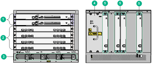
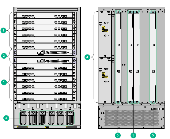
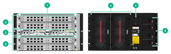
Figure1-1 CR16006-F front and rear views
|
(1) MPUs (slots 0 and 1) |
(2) Service modules (slots 2 to 5) |
(3) Power supplies |
|
(4) Fan tray |
(5) Switching fabric modules (slots 6 to 9) |
|
Figure1-2 CR16010-F (one fan tray) front and rear views
|
(1) Service modules (slots 0 to 3 and slots 6 to 9) |
(2) MPUs (slots 4 and 5) |
(3) Power supplies |
|
(4) Fan tray |
(5) Switching fabric modules (slots 10 to 13) |
|
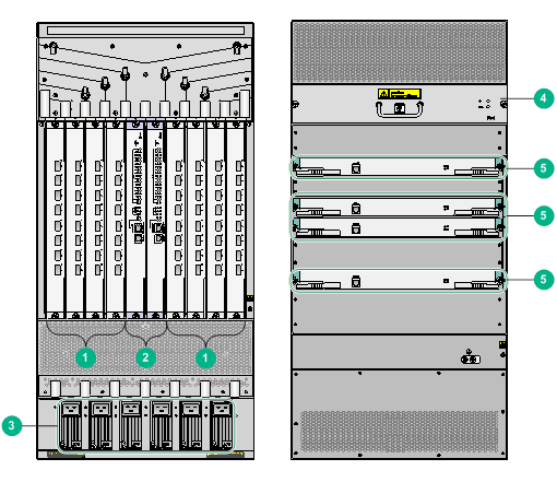
Figure1-3 CR16010-F (two fan trays) front and rear views

|
(1) Service modules (slots 0 to 3 and slots 6 to 9) |
(2) MPUs (slots 4 and 5) |
(3) Power supplies |
|
(4) Fan trays |
(5) Switching fabric modules (slots 10 to 13) |
|
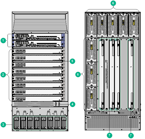
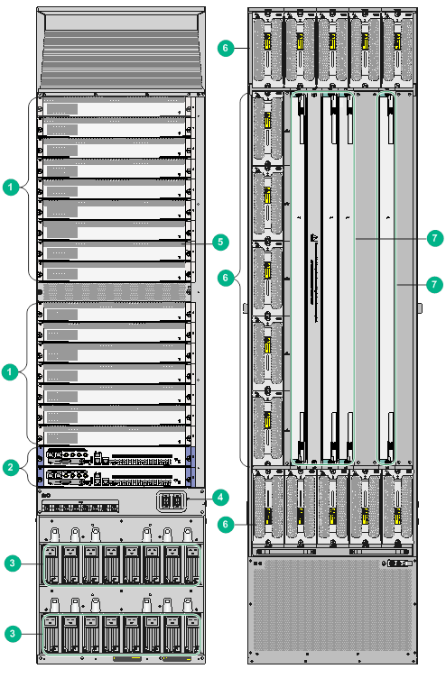
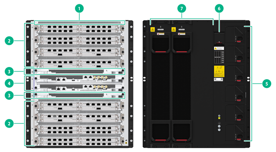
Figure1-4 CR16010H-F (five switching fabric modules)/CR16010H-FA front and rear views
|
(1) MPUs (slots 0 and 1) |
(2) Service modules (slots 2 to 9) |
(3) Power supplies |
|
(4) Power switches |
(5) Air duct |
(6) Fan trays |
|
(7) Switching fabric modules (slots 10 to 14) (slot 11 can be used only when five switching fabric modules are required) |
||
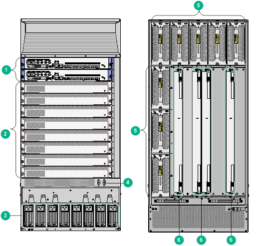
Figure1-5 CR16010H-F (four switching fabric modules) front and rear views
|
(1) MPUs (slots 0 and 1) |
(2) Service modules (slots 2 to 9) |
(3) Power supplies |
|
(4) Power switches |
(5) Fan trays |
(6) Switching fabric modules (slots 10 to 13) |
Figure1-6 CR16014-F front and rear views
|
(1) Service modules (slots 0 to 5 and slots 8 to 13) |
(2) MPUs (slots 6 and 7) |
(3) Power supplies |
|
(4) Fan trays |
(5) Switching fabric modules (slots 14 to 17) |
|
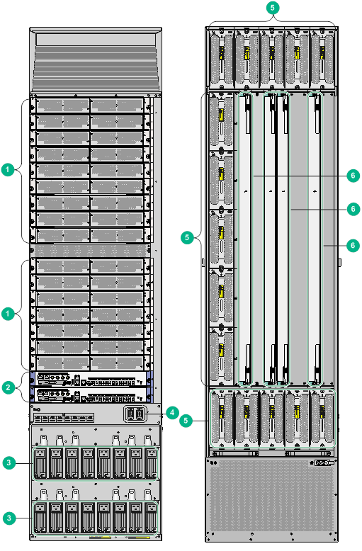
Figure1-7 CR16018-F (five switching fabric modules)/CR16018-FA front and rear views
|
(1) Service modules (slots 0 to 15) |
(2) MPUs (slots 16 and 17) |
(3) Power supplies |
|
(4) Power switches |
(5) Air duct |
(6) Fan trays |
|
(7) Switching fabric modules (slots 18 to 22) (slot 19 can be used only when five switching fabric modules are required) |
||
Figure1-8 CR16018-F (four switching fabric modules) front and rear views
|
(1) Service modules (slots 0 to 15) |
(2) MPUs (slots 16 and 17) |
(3) Power supplies |
|
(4) Power switches |
(5) Fan trays |
|
|
(6) Switching fabric modules (slots 18 to 21) |
||
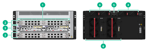
Figure1-9 CR16003E-F front and rear views
|
(1) Air duct |
(2) Service modules (slots 2 and 3) |
(3) MPUs (slots 0 and 1) |
|
(4) Power supplies |
(5) Power switch |
(6) Fan trays |
Figure1-10 CR16005E-F front and rear views
|
(1) Air duct |
(2) Service modules (slots 2 to 5) |
(3) MPUs (slots 0 and 1) |
|
(4) Power supplies |
(5) Power switch |
(6) Fan trays |
Figure1-11 CR16010E-F front and rear views
|
(1) Air duct |
(2) Service modules (slots 0 to 7) |
(3) Switching fabric modules (slots 10 and 11) |
|
(4) MPUs (slots 8 and 9) |
(5) Power supplies |
(6) Power switch |
|
(7) Fan trays (comes with two fan trays and supports up to three fan trays) |
||
Device slots and slot numbering
Module slot numbering
The slot numbering sequence for all models of CR16000-F follows the principle of front-to-back, top-to-bottom, and left-to-right.
Table1-1 Module slot numbering
|
MPU location |
Model |
Numbering |
|
Upper front |
CR16006-F, CR16010H-F, and CR16010H-FA |
See Figure1-12 (CR16006-F is used as an example) |
|
Middle upper |
CR16010-F, CR16014-F, CR16003E-F, CR16005E-F, CR16010E-F |
See Figure1-13 (CR16014-F is used as an example) |
|
Lower front |
CR16018-F (four switching fabric modules), CR16018-F (five switching fabric modules), and CR16018-FA |
See Figure1-14 (CR16018-F with five switching fabric modules is used as an example) |
Figure1-12 Slot numbering on the CR16006-F
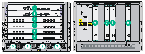
Figure1-13 Slot numbering on the CR16014-F
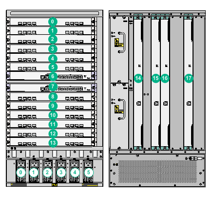
Figure1-14 Slot numbering on the CR16018-F (five switching fabric modules)
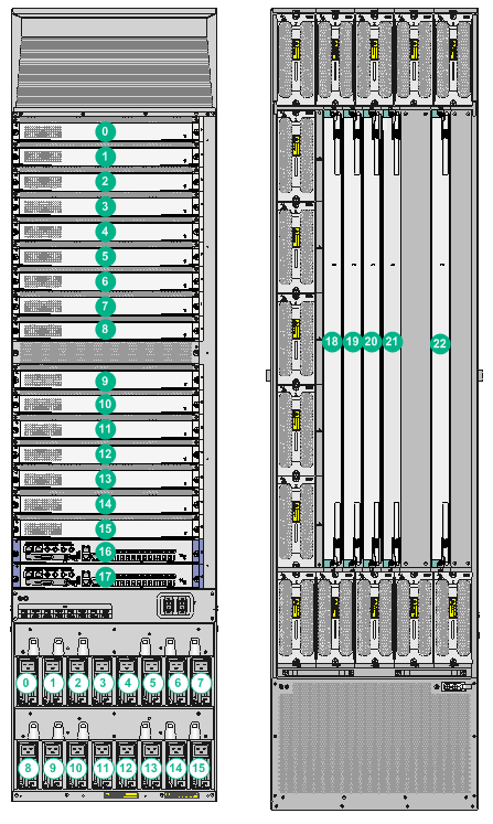
Figure1-15 Slot numbering on the CR16003E-F
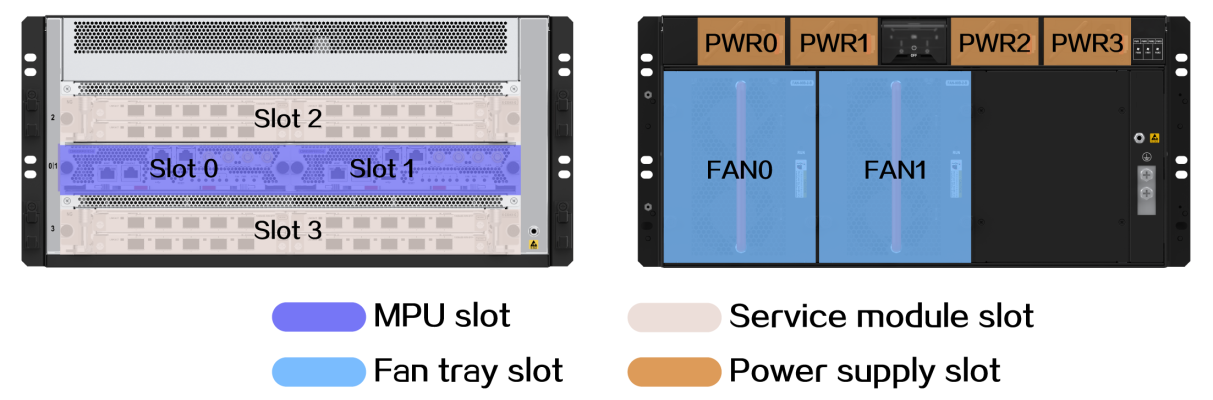
|
Slot 0 and Slot 1: MPU slots |
Slot 2 and Slot 3: Service module slots |
|
PWR 0 to PWR 3: Power supply slots |
FAN 0 and FAN 1: Fan tray slots |
Figure1-16 Slot numbering on the CR16005E-F
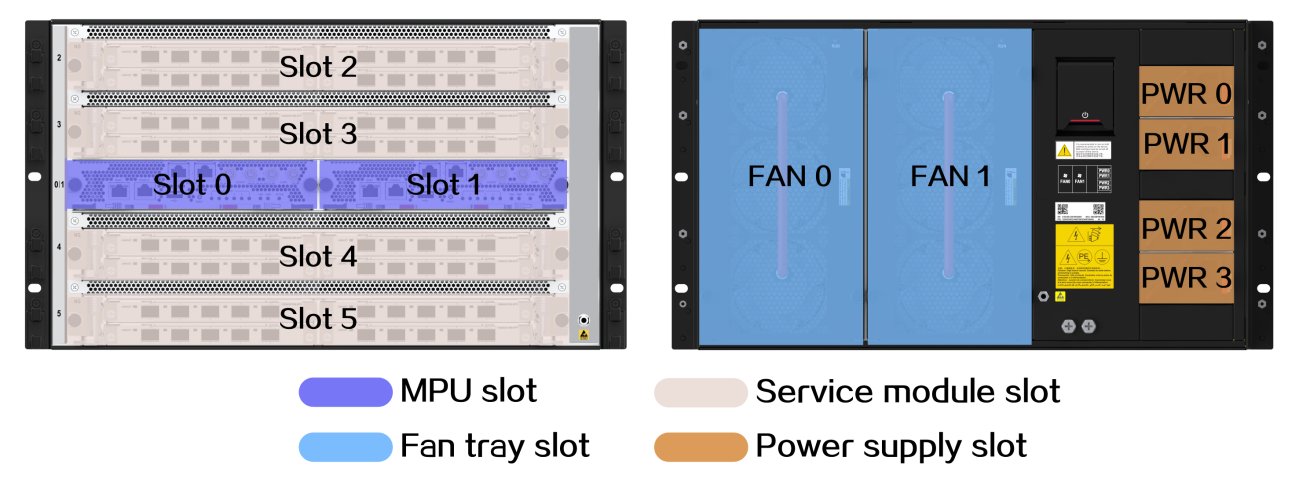
|
Slot 0 and Slot 1: MPU slots |
Slot 2 to Slot 5: Service module slots |
|
PWR 0 to PWR 3: Power supply slots |
FAN 0 and FAN 1: Fan tray slots |
Figure1-17 Slot numbering on the CR16010E-F
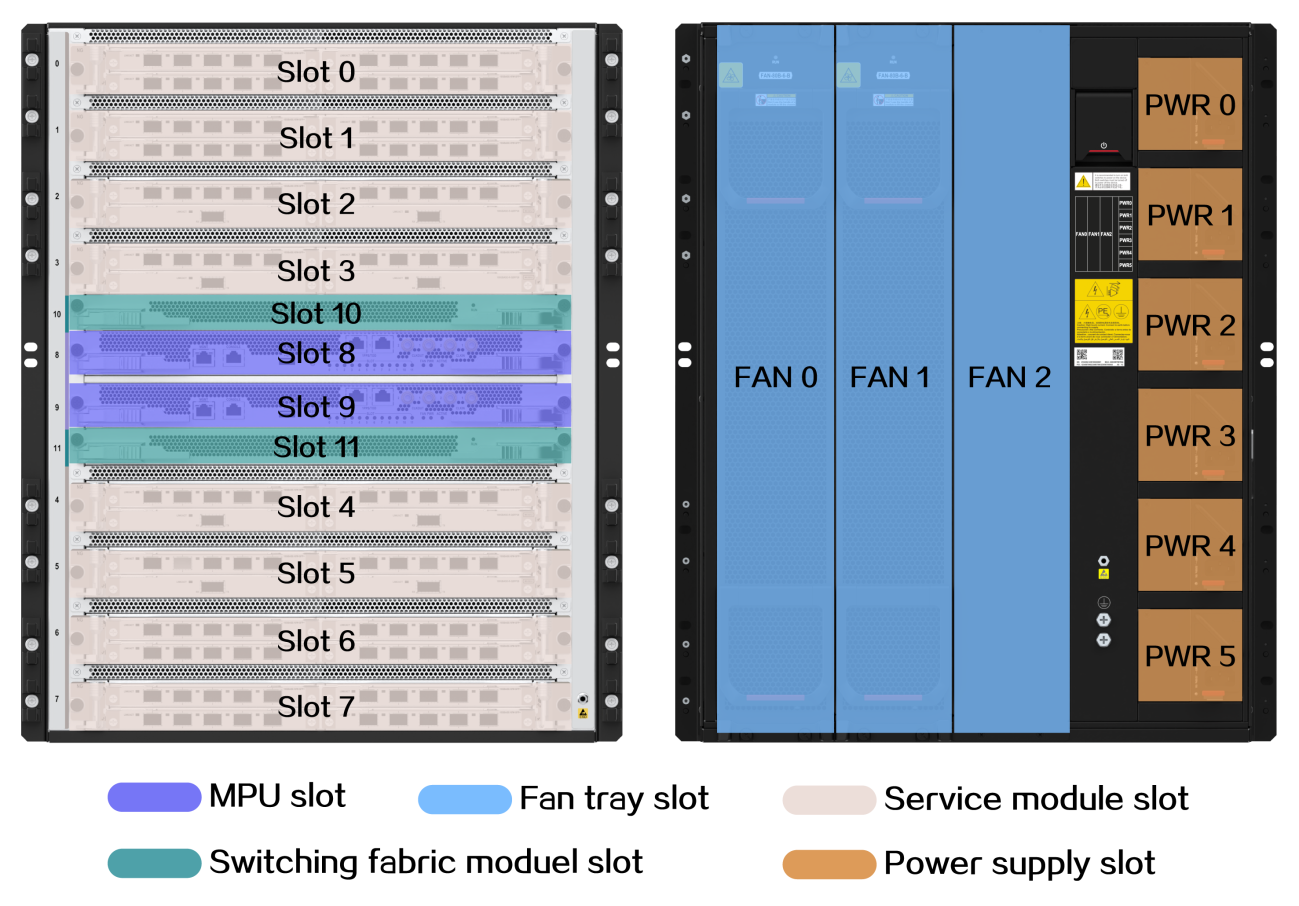
|
Slot 8 and Slot 9: MPU slots |
Slot 0 to Slot 7: Service module slots |
|
PWR 0 to PWR 5: Power supply slots |
FAN 0 to FAN 2: Fan tray slots |
|
Slot 10 and Slot 11: Switching fabric module slots |
|
Interface module slot numbering and interface numbering
The slot numbering sequence for all interface modules follows the principle of top-to-bottom and left-to-right.
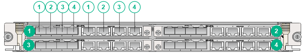
For example, as shown in Figure1-18, if you install MIC-GP4L interface modules on the CSPEX-1504X, white-background numbers represent interface numbers, and green-background numbers represent slot numbers. The fiber and copper ports of a combo interface are numbered in pairs.
Figure1-18 Subslot numbering and interface numbering
Power supply slot numbering
The slot numbering sequence for all models of CR16000-F follows the principle of left-to-right and top-to-bottom.
· For example, on the CR16006-F, the power supply slots are number 0 through 3 from the left to right, as shown by the white-background numbers in Figure1-12.
· For example, on the CR16014-F, the power supply slots are number 0 through 5 from the left to right, as shown by the white-background numbers in Figure1-13.
· For example, on the CR16018-F, the power supply slots in the first row are numbered 0 through 7 and the slots in the second row are numbered 8 through 15 from the left to right, as shown by the white-background numbers in Figure1-14.
Module slots
Table1-2 Slots for MPUs, service modules, and switching fabric modules
|
SRPU |
Installation slots |
|
MPUs |
CR16006-F: Slot 0 and Slot1 CR16010-F (single fan tray): Slot 4 and Slot 5 CR16010-F (dual fan trays): Slot 4 and Slot 5 CR16010H-F: Slot 0 and Slot 1 CR16010H-FA: Slot 0 and Slot 1 CR16014-F: Slot 6 and Slot 7 CR16018-F: Slot 16 and Slot 17 CR16018-FA: Slot 16 and Slot 17 CR16003E-F: Slot 0 and Slot 1 CR16005E-F: Slot 0 and Slot 1 CR16010E-F: Slot 8 and Slot 9 |
|
Service modules |
CR16006-F: Slot 2 through Slot 5 CR16010-F (single fan tray): Slot 0 through Slot 3, Slot 6 through Slot 9 CR16010-F (dual fan trays): Slot 0 through Slot 3, Slot 6 through Slot 9 CR16010H-F: Slot 2 through Slot 9 CR16010H-FA: Slot 2 through Slot 9 CR16014-F: Slot 0 through Slot 5, Slot 8 through Slot 13 CR16018-F: Slot 0 through Slot 15 CR16018-FA: Slot 0 through Slot 15 CR16003E-F: Slot 2 and Slot 3 CR16005E-F: Slot 2 through Slot 5 CR16010E-F: Slot 0 through Slot 7 |
|
Switching fabric modules |
CR16006-F: Slot 6 through Slot 9 CR16010-F (single fan tray): Slot 10 through Slot 13 CR16010-F (dual fan tray): Slot 10 through Slot 13 CR16010H-FA: Slot 10 through Slot 14 CR16010H-F (five switching fabric modules): Slot 10 through Slot 14 CR16010H-F (four switching fabric modules): Slot 10 through Slot 13 CR16014-F: Slot 14 through Slot 17 CR16018-FA: Slot 18 through Slot 22 CR16018-F (five switching fabric modules): Slot 18 through Slot 22 CR16018-F (four switching fabric modules): Slot 18 through Slot 21 CR16010E-F: Slot 10 and Slot11 |
Interface numbering
Interface numbering
The CR16000-F supports varies types of interfaces, including console ports, USB console ports, GE ports, XGE ports, network management ports, and POS interfaces.
The interfaces are numbered according to the following rules:
The number of an interface is in the interface-type slot/subslot/num format, where:
· interface-type: Represents the interface type, such as GigabitEthernet and POS.
· slot: Represents the number of the module slot. For more information, see the green-background numbers in Figure1-12, Figure1-13, and Figure1-14.
· subslot: Represents the number of the subslot, a slot on a CSPEX, CMPE, or SPE interface module. For more information, see the green-background numbers in Figure1-18. For a CSPC, CEPC, or OAA module, the subslot number is 0.
· num: Specifies the interface number, the number of the interface on a CSPC, CEPC, or OAA module or on an interface module. For more information, see the white-background numbers in Figure1-18. Note that each combo interface contains one SFP fiber port and one RJ-45 copper port. The fiber port and copper port are numbered in pairs.
Note that:
· In an IRF fabric, the number of a router is in the chassis/slot/subslot/num format, where chassis represents the member device number in the IRF fabric. For example, on a device with member number 1, interfaces on the device are numbered in the interface-type 1/slot/subslot/num format. For more information about member numbering in IRF, see H3C CR16000-F Routers Configuration Guides.
· For different interface submodules on the same CSPEX, CMPE, or SPE module, their slot numbers are the same.
· For different interfaces on the same interface submodule, their subslot numbers are the same.
· The interface number for each type of interfaces starts from 1 and is consistent with the interface number on the CSPC, CEPC, or OAA module or interface sub-module.
· The management interface number is independent of the installation slot of the MPU on the router, and the slot number, subslot number, and interface number for the management interface are all fixed to 0.
Interface numbering example
· Two CSR05SRP1L1 MPUs are installed on the CR16006-F
The number of MPU network management interface M-GigabitEthernet is fixed to M-GigabitEthernet 0/0/0.
· One MIC-GP4L submodule is installed in the CSPEX-1504X module in slot 3 on the router.
¡ If an MIC-GP4L interface submodule is installed in slot 1 on the CSPEX-1504X, GigabitEthernet interfaces on the submodule are numbered as follows:
- GigabitEthernet 3/1/1
- GigabitEthernet 3/1/2
- GigabitEthernet 3/1/3
- GigabitEthernet 3/1/4
¡ If an MIC-GP4L interface submodule is installed in slot 2 on the CSPEX-1504X, GigabitEthernet interfaces on the submodule are numbered as follows:
- GigabitEthernet 3/2/1
- GigabitEthernet 3/2/2
- GigabitEthernet 3/2/3
- GigabitEthernet 3/2/4
¡ If an MIC-GP4L interface submodule is installed in slot 3 on the CSPEX-1504X, GigabitEthernet interfaces on the submodule are numbered as follows:
- GigabitEthernet 3/3/1
- GigabitEthernet 3/3/2
- GigabitEthernet 3/3/3
- GigabitEthernet 3/3/4
¡ If an MIC-GP4L interface submodule is installed in slot 4 on the CSPEX-1504X, GigabitEthernet interfaces on the submodule are numbered as follows:
- GigabitEthernet 3/4/1
- GigabitEthernet 3/4/2
- GigabitEthernet 3/4/3
- GigabitEthernet 3/4/4
· One CSPC-GP48LB module is installed in slot 3 on the router
GigabitEthernet interfaces on the CSPC-GP48LB are numbered GigabitEthernet 3/0/1 through GigabitEthernet 3/0/48.
Technical specifications
Table1-3 Technical specifications (1)
|
Item |
CR16006-F |
CR16010-F (single fan tray) |
CR16010-F (dual fan trays) |
|
Cabinet requirements |
19 inches |
19 inches |
19 inches |
|
Chassis height |
8 RUs |
20 RUs |
21 RUs |
|
Physical dimensions (H × W × D) |
353 × 440 × 660 mm (13.90 × 17.32 × 25.98 in) |
886 × 440 × 660 mm (34.88 × 17.32 × 25.98 in) |
930 × 440 × 660 mm (36.61 × 17.32 × 25.98 in) |
|
Max. weight (fully configured) |
≤ 76 kg (167.55 lb) |
≤ 120 kg (264.55 lb) |
≤ 170 kg (374.78 lb) |
|
Availability |
99.999% |
99.999% |
99.999% |
|
Heat dissipation |
Fan cooling |
Fan cooling |
Fan cooling |
|
Airflow direction |
Left-to-right |
Front-to-back |
Front-to-back |
|
Total number of slots |
15 |
21 |
22 |
|
Number of MPU slots |
2 |
2 |
2 |
|
Number of service modules |
4 |
8 |
8 |
|
Number of switching fabric modules |
4 |
4 |
4 |
|
Number of power supply slots |
4 |
6 |
6 |
|
Number of fan tray slots |
1 |
1 |
2 |
|
Noise level |
· Fan noise (room temperature): 62.3 dBA · Fan noise (full fan speed): 75.5 dBA |
· Fan noise (room temperature): 61.6 dBA · Fan noise (full fan speed): 72.6 dBA |
· Fan noise (room temperature): 65.7 dBA · Fan noise (full fan speed): 73.3 dBA |
|
Weight |
Chassis (including mounting brackets and filler panels) + modules + power supplies + fan trays + swappable interface modules + other swappable modules |
||
|
Power consumption |
Min router power consumption = Static power consumption of modules + Min fan tray power consumption Max router power consumption = Dynamic consumption of modules + Max fan tray power consumption |
||
|
Heat dissipation volume |
Heat dissipation volume per hour = 0.9*Total power consumption/0.9*3.4121 |
||
|
Temperature |
· Operating temperature: 0°C to 45°C (32°F to 113°F) · Not Operating temperature: –40°C to +70°C (–40°F to +158°F) |
||
|
Operating temperature change |
≤ 30°C (86°F) per hour |
||
|
Relative humidity |
· Operating humidity: 10% to 95% RH, non-condensing · Storage humidity: 5% to 95% RH, non-condensing |
||
|
Altitude |
≤ 5000 m (16404.20 ft) |
||
Table1-4 Technical specifications (2)
|
Item |
CR16010H-F (four switching fabric modules) CR16010H-F (five switching fabric modules) CR16010H-FA |
CR16014-F |
CR16018-F (four switching fabric modules) CR16018-F (five switching fabric modules) CR16018-FA |
|
Cabinet requirements |
19 inches |
19 inches |
19 inches |
|
Chassis height |
21 RUs |
18 RUs |
38 RUs |
|
Physical dimensions (H × W × D) |
931 × 440 × 640 mm (36.65 × 17.32 × 25.20 in) |
797 × 440 × 660 mm (31.38 × 17.32 × 25.20 in) |
1687 × 440 × 640 mm (66.42 × 17.32 × 25.20 in) |
|
Max. weight (fully configured) |
≤ 245 kg (540.12 lb) |
≤ 174 kg (383.60 lb) |
≤ 440 kg (970.02 lb) |
|
Availability |
99.999% |
99.999% |
99.999% |
|
Heat dissipation |
Fan cooling |
Fan cooling |
Fan cooling |
|
Airflow direction |
Front-to-back |
Left-to-right |
Front-to-back |
|
Total number of slots |
· CR16010H-F (four switching fabric modules): 30 · CR16010H-F (five switching fabric modules) and CR16010H-FA: 31 |
26 |
· CR16018-F (four switching fabric modules): 53 · CR16018-F (five switching fabric modules) and CR16018-FA: 54 |
|
Number of MPU slots |
2 |
2 |
2 |
|
Number of service modules |
8 |
12 |
16 |
|
Number of switching fabric modules |
· CR16010H-F (four switching fabric modules): 4 · CR16010H-F (five switching fabric modules) and CR16010H-FA: 5 |
4 |
· CR16018-F (four switching fabric modules): 4 · CR16018-F (five switching fabric modules) and CR16018-FA: 5 |
|
Number of power supply slots |
8 |
6 |
16 |
|
Number of fan tray slots |
8 |
2 |
15 |
|
Noise level |
· Fan noise (room temperature): 66.4 dBA · Fan noise (full fan speed): 84.0 dBA |
· Fan noise (room temperature): 66 dBA · Fan noise (full fan speed): 79 dBA |
· Fan noise (room temperature): 75.9 dBA · Fan noise (full fan speed): 91 dBA |
|
Weight |
Chassis (including mounting brackets and filler panels) + modules + power supplies + fan trays + swappable interface modules + other swappable modules |
||
|
Power consumption |
Min router power consumption = Static power consumption of modules + Min fan tray power consumption Max router power consumption = Dynamic consumption of modules + Max fan tray power consumption |
||
|
Heat dissipation volume |
Heat dissipation volume per hour = 0.9*Total power consumption/0.9*3.4121 |
||
|
Temperature |
· Operating temperature: 0°C to 45°C (32°F to 113°F) · Not Operating temperature: –40°C to +70°C (–40°F to +158°F) |
||
|
Operating temperature change |
≤ 30°C (86°F) per hour |
||
|
Relative humidity |
· Operating humidity: 10% to 95% RH, non-condensing · Storage humidity: 5% to 95% RH, non-condensing |
||
|
Altitude |
≤ 5000 m (16404.20 ft) |
||
Table1-5 Technical specifications (3)
|
Item |
CR16003E-F |
CR16005E-F |
CR16010E-F |
|
Rack type |
19-inch standard rack |
19-inch standard rack |
19-inch standard rack |
|
Chassis height |
5 RUs |
6 RUs |
13 RUs |
|
Physical dimensions (H × W × D) |
220 × 440 × 481 mm (8.66 × 17.32 × 18.94 in) |
267 × 440 × 602 mm (10.51 × 17.32 × 23.70 in) |
578 × 440 × 602 mm (22.76 × 17.32 × 23.70 in) |
|
Max. weight (fully configured) |
≤ 62.7 kg (138.23 lb) |
≤ 100 kg (220.46 lb) |
≤ 200 kg (440.92 lb) |
|
Availability |
99.999% |
99.999% |
99.999% |
|
Heat dissipation |
Fan tray cooling |
Fan tray cooling |
Fan tray cooling |
|
Airflow direction |
From front to rear |
From front to rear |
From front to rear |
|
Total slots |
10 |
12 |
20 |
|
MPU slots |
2 |
2 |
2 |
|
Service module slots |
2 |
4 |
8 |
|
Switching fabric module slots |
N/A |
N/A |
2 |
|
Power supply slots |
4 |
4 |
6 |
|
Fan tray slots |
2 |
2 |
2 |
|
Noise level |
· Fan noise (normal temperature): 70.4 dBA · Fan noise (full fan speed): 77.5 dBA |
· Fan noise (normal temperature): 56.5 dBA · Fan noise (full fan speed): 77.9 dBA |
· Fan noise (normal temperature): 60.2 dBA · Fan noise (full fan speed): 77.4 dBA |
|
Weight |
Chassis weight (including mounting brackets and filler panels) plus removable component weights (including cards, power supplies, fan trays, removable interface components, and other removable components) |
||
|
Power consumption |
· Minimum system power consumption: static power consumption of all cards + minimum power consumption of all fan trays · Maximum system power consumption: dynamic power consumption of all cards + maximum power consumption of all fan trays |
||
|
Heat dissipation volume (per hour) |
0.9 × system power consumption/0.9 × 3.4121 |
||
|
Temperature |
· Operating: 0°C to 45°C (32°F to 113°F) · Storage: –40°C to +70°C (–40°F to +158°F) |
||
|
Operating temperature change |
≤ 30°C/hour (86°F/hour) |
||
|
Relative humidity |
· Operating: 10% RH to 95% RH (noncondensing) · Storage: 5% RH to 95% RH (noncondensing) |
||
|
Altitude |
≤ 5000 m (16404.20 ft) |
||
|
|
NOTE: · Rack Unit (RU) is a measurement unit used to indicate the height of a rack. 1 RU is equal to 44.45 mm (1.75 in). · The dimension data refers to the size value of the chassis itself and does not include the dimensions of chassis ears, cable management brackets, modules, power supplies, and other installed components and accessories. · The heat generated by the device is closely related to its power consumption. It is generally assumed that 90% of the power consumption is converted to heat, and the power supply's conversion efficiency is 90%. The unit of heat is generally measured in BTU/h, and 1 watt is equal to 3.4121 BTU/h. · The noise value is tested using the bystander sound pressure level test method of ISO 7779. · For information about the power consumption of each component, see "Appendix B FRUs and compatibility matrixes." |
