| Title | Size | Downloads |
|---|---|---|
| H3C Data Center Switches S-MLAG Best Practices-6W100-book.pdf | 495.13 KB |
- Table of Contents
- Related Documents
-
|
|
|
H3C Data Center Switches |
|
S-MLAG Best Practices |
|
|
|
|
Document version: 6W100-20221230
Copyright © 2022 New H3C Technologies Co., Ltd. All rights reserved.
No part of this manual may be reproduced or transmitted in any form or by any means without prior written consent of New H3C Technologies Co., Ltd.
Except for the trademarks of New H3C Technologies Co., Ltd., any trademarks that may be mentioned in this document are the property of their respective owners.
The information in this document is subject to change without notice.
Contents
Comparison of S-MLAG, IRF, and M-LAG
General configuration restrictions and guidelines
Security and high availability settings
Applicable hardware and software versions
Device isolation operation guides
Leaf device isolation operation guide
Spine device isolation operation guide
Introduction
About S-MLAG
Simple Multichassis Link Aggregation (S-MLAG) virtualizes two physical devices into one system through simple multichassis link aggregation. This feature is applicable to server connection scenarios that require device-level redundancy protection and traffic load balancing.
Comparison of S-MLAG, IRF, and M-LAG
Intelligent Resilient Framework (IRF) is a software virtualization technology proprietary to H3C. This technology virtualizes multiple physical devices at the same layer into one virtual fabric to provide data center class availability and scalability. IRF virtualization technology offers processing power, interaction, unified management, and uninterrupted maintenance of multiple devices.
Multichassis link aggregation (M-LAG) is a multichassis link aggregation technology that virtualizes two physical devices into one system through multichassis link aggregation to provide device-level redundancy protection and traffic load balancing.
IRF, M-LAG, and S-MLAG all can provide device-level redundancy protection and traffic load balancing. Table 1 shows the comparison among them.
Table 1 Comparison of IRF, M-LAG, and S-MLAG
|
Item |
IRF |
M-LAG |
S-MLAG |
|
Control plane |
· All member devices use a unified control plane for unified management. · All entries must be synchronized among all member devices. · Dedicated physical links called IRF links must be established among member devices. |
· The member devices are decoupled on the control plane as independent devices, which reduces O&M risks. · The member devices mainly synchronize MAC entries, ARP entries, and ND entries. · The member devices are connected through the peer link. |
· The member devices are decoupled on the control plane as independent devices, which reduces O&M risks. · The member devices do not need to synchronize MAC entries, ARP entries, or ND entries. They use BGP host route synchronization for entry synchronization and require that all packets are forwarded at Layer 3. You need to configure ARP proxy on the gateways and prevent servers from broadcasting ARP packets. · The member devices do not have a peer link between them. They operate in dual-active mode. Ensure that the servers connected to the member devices can send ARP packets to both the member devices. |
|
Software upgrade |
All member devices synchronously upgrade software or use a complex method to separately upgrade software for the master and subordinate devices. Services are interrupted for about 2 seconds during software upgrade. |
· The member devices in an M-LAG system can independently upgrade software. Services are interrupted for less than 1 second during software upgrade. · For versions that support graceful insertion and removal (GIR), you can upgrade software for the member devices without service interruption. |
The member devices in an S-MLAG system can independently upgrade software. The service interruption time during software upgrade is very short. For example, the service interruption time is 79 milliseconds in R6635 on the S6850 switch series. |
|
Configuration management |
Unified configuration, unified management, and simple operation. |
Independent and complex configuration. |
Independent and complex configuration. |
|
Troubleshooting |
When a link connected to a server fails on one IRF member device, IRF delivers inter-server traffic to the neighboring IRF member device through an IRF physical link for forwarding. |
When a link connected to a server fails on one M-LAG member device, M-LAG delivers inter-server traffic to the peer M-LAG member device through the peer link for forwarding. |
When a link connected to a server fails on one S-MLAG member device, S-MLAG delivers half of the inter-server traffic on the S-MLAG system to upper tier devices for forwarding. |
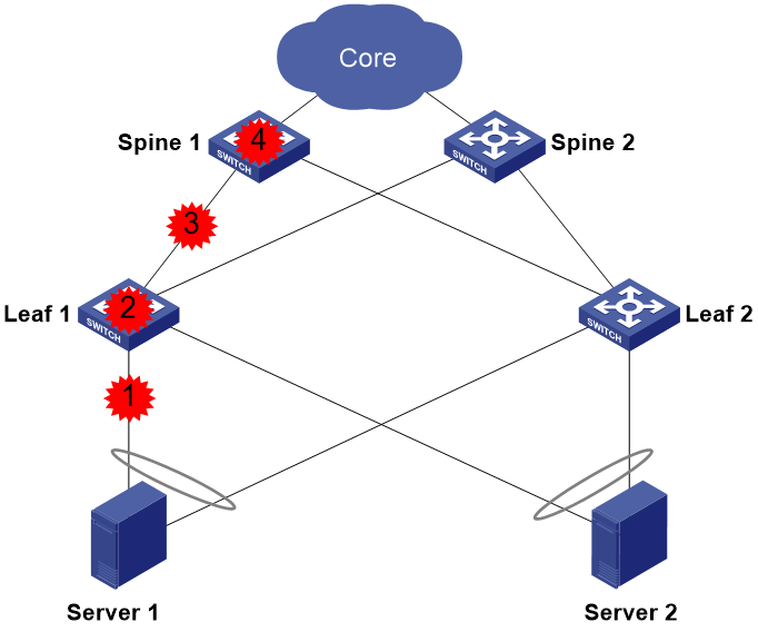
Typical network models
Network models
Configure S-MLAG on each two leaf deices to provide device-level redundancy protection and traffic load balancing for servers.
On each pair of leaf devices, configure VLAN dual-active gateways. On the gateway interfaces, enable local ARP proxy. The servers can learn only the MAC addresses of the gateways and access other servers or devices at Layer 3.
The leaf and spine devices load share traffic through EBGP ECMP routes. The following methods are available for configuring BGP routing:
· All spine devices are configured with the same AS number, and all leaf devices are configured with the same AS number.
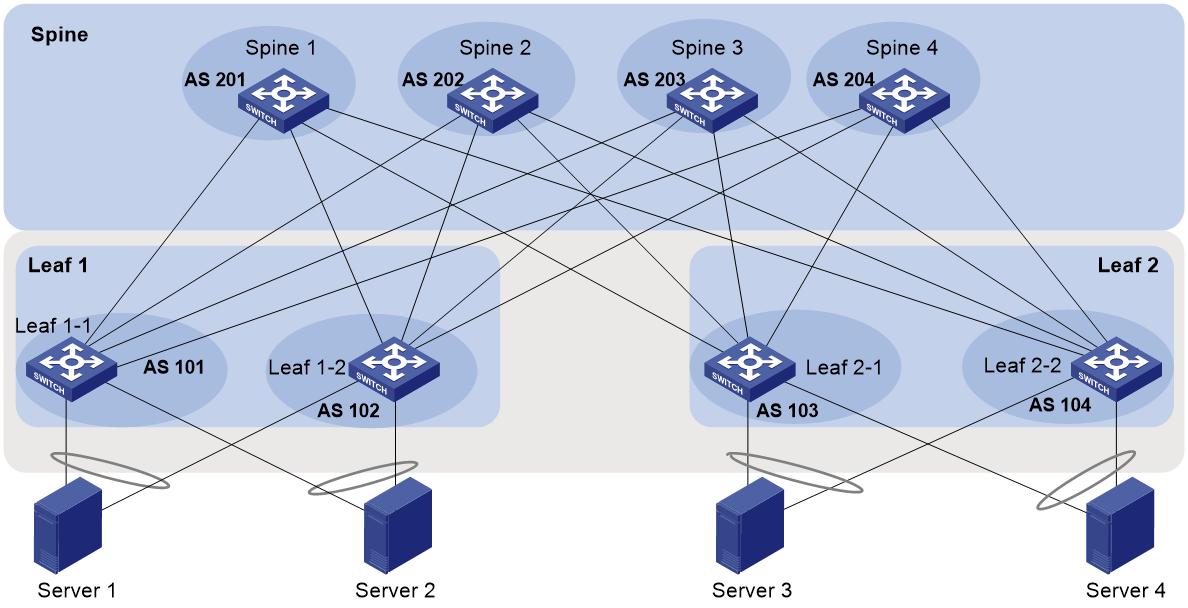
· All spine and leaf devices are configured with different AS numbers.
|
|
IMPORTANT: To use this method, make sure the number of network nodes is less than 1000 to reduce the computing workload of the network nodes. |
For more information about the methods, see "Routing configuration methods."
On the leaf devices, configure Monitor Link settings. Configure all interfaces connected to the spine devices as uplink interfaces and all interfaces connected to the servers as downlink interfaces. Associate the uplink and downlink interfaces in a monitor link group so that the leaf devices can switch over uplink traffic from a server connected to one leaf device to other links when the uplink interface of that leaf device goes down.
Figure 1 S-MLAG network diagram (routing method 1)
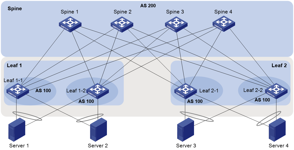
Figure 2 S-MLAG network diagram (routing method 2)
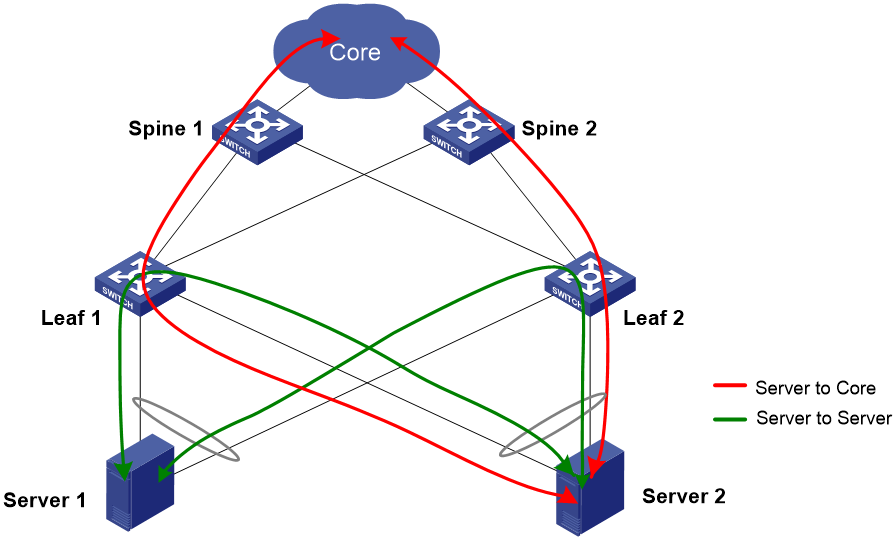
Traffic models
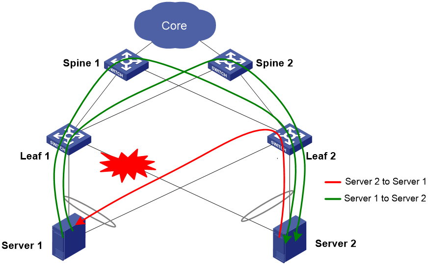
In normal situations, the servers communicate with each other and communicate with the core network, as shown in Figure 3.
Figure 3 Traffic forwarding paths in normal situations
When a downlink of a leaf device fails, the servers communicate with each other as shown in Figure 4.
Figure 4 Inter-server traffic forwarding paths when a downlink of a leaf device fails
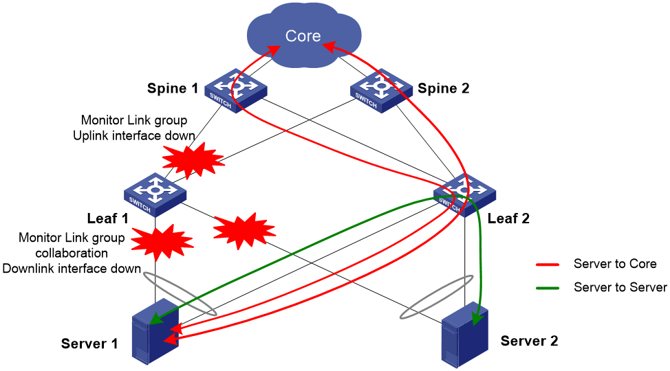
When the uplink of a leaf device fails, the servers communicate with each other and communicate with the core network, as shown in Figure 5.
Figure 5 Traffic forwarding paths when the uplink of a leaf device fails
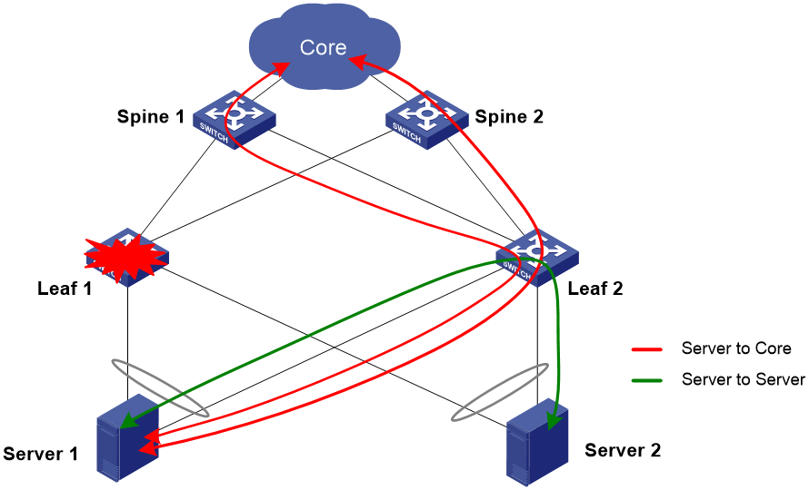
When a leaf device fails, the servers communicate with each other and communicate with the core network, as shown in Figure 6.
Figure 6 Traffic forwarding paths when a leaf device fails
General configuration restrictions and guidelines
When the server NICs operate in bond4 operating mode, the aggregation groups of the aggregate interfaces connected to them on the access switches must operate in dynamic aggregation mode. In addition, make sure both the uplink interfaces of each server can send ARP packets so that both the access switches can learn the ARP entries of the servers. When any member port of the aggregation groups at the server side comes up, the server connected to the port sends ARP packets to the access switch where the port resides, so that the switch can refresh the ARP entry and generate a host route for the server.
When the server NICs operate in bond1 (active/standby) operating mode, follow these restrictions and guidelines:
· The aggregation groups of the aggregate interfaces connected to the servers on the access switches can operate in dynamic or static aggregation mode. Ensure that the NIC of each server can send ARP packets to the connected access switch when the NIC interface changes from inactive to active. The ARP packets help the access switches refresh ARP entries and generate host routes for the servers.
· When dynamic aggregation mode is used, configure the aggregate interfaces that connect the access switches and servers as edge aggregate interfaces by using the lacp edge-port command.
· As a best practice, set the ARP aging time to 30 seconds. The configuration ensures that an access switch can refresh ARP entries and generate host routes in time to reduce packet loss when the NIC interface of a server connected to the switch becomes inactive but its state does not change to down. As a best practice to reduce CPU burden, do not set the ARP aging time to a smaller value.
Example: Configuring S-MLAG
Network configuration
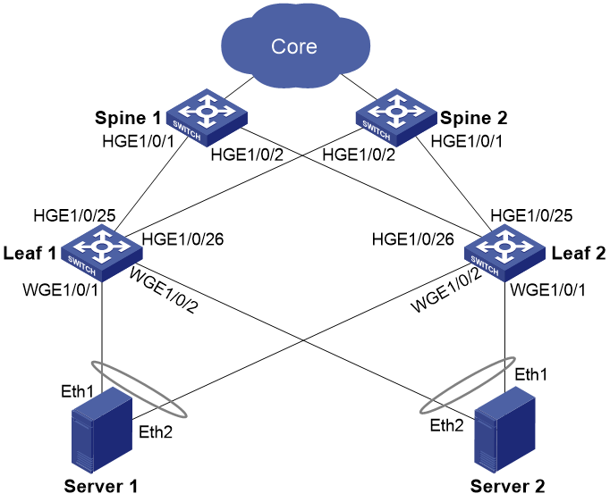
As shown in Figure 7:
· Leaf 1 and Leaf 2 that act as access devices are connected to the Layer 2 Ethernet interfaces of Server 1 and Server 2 through Layer 2 Ethernet interfaces.
· The server NICs operate in bond4 operating mode.
Configure the devices and servers as follows:
· Configure S-MLAG settings for the servers to be dual-homed to the leaf devices through aggregate interfaces. The settings provide redundancy protection and traffic load balancing for servers.
· Configure Server 1 and Server 2 to automatically obtain IPv4 and IPv6 addresses to facilitate user server installation.
· Configure Leaf 1 and Leaf 2 to act as dual-active gateways for Server 1 and Server 2. The servers communicate with each other and communicate with the core network at Layer 3. For high security, prevent Leaf 1 and Leaf 2 from disclosing ARP packets and ND packets not generated on the local device to other devices.
· For high availability and service traffic protection, configure Leaf 1 and Leaf 2 to dynamically detect the availability of the uplink interfaces and shut down the corresponding downlink interface when an uplink interface fails.
|
Device |
Interface |
Address |
Interface remarks and connections |
|
Leaf 1 |
Vlan-int100 |
100.1.1.1 |
Server gateway interface |
|
100::1 |
|||
|
LoopBack0 |
1.1.1.1 |
N/A |
|
|
1::1 |
|||
|
HGE1/0/25 |
101.1.1.1 |
Uplink interface connected to HGE 1/0/1 of Spine 1 |
|
|
101::1 |
|||
|
HGE1/0/26 |
103.1.1.1 |
Uplink interface connected to HGE 1/0/2 of Spine 2 |
|
|
103::1 |
|||
|
WGE1/0/1 |
N/A |
S-MLAG aggregate member port connected to Server 1 |
|
|
WGE1/0/2 |
N/A |
S-MLAG aggregate member port connected to Server 2 |
|
|
Leaf 2 |
Vlan-int100 |
100.1.1.1 |
Server gateway interface |
|
100::1 |
|||
|
LoopBack0 |
2.2.2.2 |
N/A |
|
|
2::2 |
|||
|
HGE1/0/25 |
102.1.1.1 |
Uplink interface connected to HGE 1/0/1 of Spine 2 |
|
|
102::1 |
|||
|
HGE1/0/26 |
104.1.1.1 |
Uplink interface connected to HGE 1/0/2 of Spine 1 |
|
|
104::1 |
|||
|
WGE1/0/1 |
N/A |
S-MLAG aggregate member port connected to Server 2 |
|
|
WGE1/0/2 |
N/A |
S-MLAG aggregate member port connected to Server 1 |
|
|
Spine 1 |
LoopBack0 |
3.3.3.3 |
N/A |
|
3::3 |
N/A |
||
|
HGE1/0/1 |
101.1.1.2 |
Downlink interface connected to HGE 1/0/25 of Leaf 1 |
|
|
101::2 |
|||
|
HGE1/0/2 |
104.1.1.2 |
Downlink interface connected to HGE 1/0/26 of Leaf 2 |
|
|
104::2 |
|||
|
Spine 2 |
LoopBack0 |
4.4.4.4 |
N/A |
|
4::4 |
N/A |
||
|
HGE1/0/1 |
102.1.1.2 |
Downlink interface connected to HGE 1/0/25 of Leaf 2 |
|
|
102::2 |
|||
|
HGE1/0/2 |
103.1.1.2 |
Downlink interface connected to HGE 1/0/26 of Leaf 1 |
|
|
103::2 |
|||
|
Server 1 |
Eth1&Eth2 |
100.1.1.22 |
Connected to Leaf 1 and Leaf 2 |
|
100::22 |
Connected to Leaf 1 and Leaf 2 |
||
|
Server 2 |
Eth1&Eth2 |
100.1.1.33 |
Connected to Leaf 1 and Leaf 2 |
|
100::33 |
Connected to Leaf 1 and Leaf 2 |
Analysis
Server dual-uplink scheme
On Leaf 1 and Leaf 2, configure S-MLAG for server dual-uplink access.
On Leaf 1 and Leaf 2, configure the same IP address and MAC address on the VLAN interfaces connected to servers, configure the VLAN interfaces as dual-active gateways, and configure direct route advertisement on the VLAN interfaces.
On the VLAN interfaces connected to the servers on the leaf devices, enable local proxy ARP and local ND proxy to ensure that hosts connected to the leaf devices that belong to the same S-MLAG system in the same subnet can communicate with each other at Layer 3.
DHCP settings
To assist servers to obtain IP addresses, configure DHCP relay on Leaf 1 and Leaf 2 to forward DHCP packets.
Routing configuration methods
Method 1
Configure BGP settings. Devices at the same tier are configured with the same AS. All leaf devices are configured with AS 100, and all spine devices are configured with AS 200. The leaf devices and spine devices establish EBGP peer relationship.
On the leaf devices, configure routing policy settings and add community attribute 0:100.
On the spine devices, configure routing policy settings to match routes with community attribute 0:100 and replace the AS number in the routes received from the leaf devices with the local AS number. The settings ensure that a leaf device can learn the routes advertised by the other leaf device. (When a device receives a route from a BGP peer, it checks the AS_PATH attribute. If the AS_PATH attribute contains its AS number, it does not learn that route.) With the settings, inter-server traffic can be forwarded to the spine devices when a downlink of a leaf device fails, as shown in Figure 4.
On the leaf devices, configure the SoO extended community attribute to ensure that the leaf devices do not advertise a route received from a spine device to the other spine device if the route has the specified SoO attribute. The configuration avoids loops.
On the spine devices, configure the SoO extended community attribute to ensure that the spine devices do not advertise a route received from a core device to the other core devices if the route has the specified SoO attribute. The configuration avoids loops.
|
|
NOTE: · The COMMUNITY attribute identifies the community of BGP routes. A BGP community is a group of routes with the same characteristics. It has no geographical boundaries. Routes of different ASs can belong to the same community. A route can carry one or more COMMUNITY attribute values (each of which is represented by a 4-byte integer). A router uses the COMMUNITY attribute to determine whether to advertise the route and the advertising scope without using complex filters such as ACLs. This mechanism simplifies routing policy configuration, management, and maintenance. · The SoO attribute specifies the site where the route originated. It prevents advertising a route back to the originating site. If the AS-path attribute is lost, the router can use the SoO attribute to avoid routing loops. |
Method 2
Configure BGP settings. All devices are configured with different ASs. On Leaf 1, configure AS 101. On Leaf 2, configure AS 102. On Spine 1, configure AS 201. On Spine 2, configure AS 202. The leaf devices and spine devices establish EBGP peer relationship.
For load balancing, you must configure routes with the same length but different AS_PATH attribute values on the leaf and spine devices. These routes can load share traffic.
On the leaf devices, configure the SoO extended community attribute to ensure that the leaf devices do not advertise a route received from a spine device to the other spine device if the route has the specified SoO attribute. The configuration avoids loops.
On the spine devices, configure the SoO extended community attribute to ensure that the spine devices do not advertise a route received from a core device to the other core devices if the route has the specified SoO attribute. The configuration avoids loops.
|
|
NOTE: · The COMMUNITY attribute identifies the community of BGP routes. A BGP community is a group of routes with the same characteristics. It has no geographical boundaries. Routes of different ASs can belong to the same community. A route can carry one or more COMMUNITY attribute values (each of which is represented by a 4-byte integer). A router uses the COMMUNITY attribute to determine whether to advertise the route and the advertising scope without using complex filters such as ACLs. This mechanism simplifies routing policy configuration, management, and maintenance. · The SoO attribute specifies the site where the route originated. It prevents advertising a route back to the originating site. If the AS-path attribute is lost, the router can use the SoO attribute to avoid routing loops. |
Security and high availability settings
On the leaf devices, configure QoS policy settings to permit only ARP packets sent from the VLAN interfaces connected to the servers. The settings prevent ARP packets from being disclosed on the other devices. If ARP leakage exists, the servers connected to the member devices in the same S-MLAG system will learn ARP information from each other. For example, Server 2 learns the ARP entry of Server 1. If the link connecting Leaf 1 to Server 1 fails, Leaf 1 cannot learn the ARP entry of Server 1. However, half of the traffic destined for Server 1 from Server 2 will be sent to Leaf 1. As a result, half of the traffic will be lost.
For a broadcast-sensitive network, for example, an RDMA network, configure broadcast, multicast, and unknown unicast storm suppression on the physical interfaces connected to the servers on the leaf devices. ND packets are multicast packets. The storm suppression settings also prevent ND leakage.
On the leaf devices, configure ARP to generate 32-bit host routes. When the link connected to a server on one S-MLAG member device fails, the S-MLAG system can update route information in time to switch over the downlink traffic to the other S-MLAG member device.
On the leaf devices, configure Monitor Link settings. When an uplink interface on one M-LAG member device goes down, the system automatically shuts down the downlink interface associated with the uplink interface to switch over the uplink traffic of the server attached to the downlink interface to the peer M-LAG member device. If you do not configure Monitor Link settings, the server cannot detect the uplink interface failure. As a result, it continuously sends traffic to the M-LAG member device where the uplink interface fails, which causes continuous traffic loss.
Applicable hardware and software versions
|
Hardware |
Software version |
|
S6805 switch series S6825 switch series S6850 switch series S9850 switch series S9820-64H switches S9820-8C switches |
R6635 |
Restrictions and guidelines
If both IPv4 and IPv6 are deployed in the network, configure the following settings on the devices as a best practice:
· Use the hardware-resource switch-mode DUAL-STACK command to configure the capacity mode of the MAC address table, ARP table, and ND table as dual-stack mode.
· Use the hardware-resource routing-mode ipv6-128 command to enable support for IPv6 routes with prefixes longer than 64 bits.
If the devices need to distinguish service types, you must use the qos trust dscp command on all interfaces to trust the DSCP value in packets.
S-MLAG settings are applicable only to Layer 2 aggregate interfaces in dynamic aggregation mode.
Configuration summary
|
Devices |
Task |
|
Leaf devices |
|
|
Configuring downlink VLAN interfaces Including configuring dual-active gateways, ARP/ND proxy, ARP/ND direct route advertisement, and DHCP relay |
|
|
Configuring downlink physical interfaces Mainly configuring unknown unicast, multicast, and broadcast packet suppression |
|
|
Spine devices |
|
Procedure
Configuring leaf devices
Configuring S-MLAG
|
Leaf 1 |
Leaf 2 |
Task |
Remarks |
|
lacp system-mac 0000-5e00-0101 |
lacp system-mac 0000-5e00-0101 |
Configure the LACP system MAC address. |
Leaf 1 and Leaf 2 must have the same value for this setting. |
|
lacp system-priority 200 |
lacp system-priority 200 |
Configure the LACP system priority. |
Leaf 1 and Leaf 2 must have the same value for this setting. |
|
lacp system-number 1 |
lacp system-number 2 |
Configure the LACP system number. |
Leaf 1 and Leaf 2 must have different LACP system numbers. |
|
interface bridge-aggregation 1 |
interface bridge-aggregation 1 |
Create Layer 2 aggregate interface 1. |
N/A |
|
link-aggregation mode dynamic |
link-aggregation mode dynamic |
Set the aggregation mode to dynamic. |
You can assign only Layer 2 dynamic aggregate interfaces to an S-MLAG group. |
|
lacp edge-port |
lacp edge-port |
Configure the aggregate interface as an edge aggregate interface. |
N/A |
|
port s-mlag group 1 |
port s-mlag group 1 |
Assign the aggregate interface to S-MLAG group 1. |
You can assign only Layer 2 dynamic aggregate interfaces to an S-MLAG group. |
|
stp edged-port |
stp edged-port |
Configure the aggregate interface as a spanning tree edge port. |
N/A |
|
quit |
quit |
Exit interface view. |
N/A |
|
interface bridge-aggregation 2 |
interface bridge-aggregation 2 |
Create Layer 2 aggregate interface 2. |
N/A |
|
link-aggregation mode dynamic |
link-aggregation mode dynamic |
Set the aggregation mode to dynamic. |
You can assign only Layer 2 dynamic aggregate interfaces to an S-MLAG group. |
|
lacp edge-port |
lacp edge-port |
Configure the aggregate interface as an edge aggregate interface. |
N/A |
|
port s-mlag group 2 |
port s-mlag group 2 |
Assign the aggregate interface to S-MLAG group 2. |
You can assign only Layer 2 dynamic aggregate interfaces to an S-MLAG group. |
|
stp edged-port |
stp edged-port |
Configure the aggregate interface as a spanning tree edge port. |
N/A |
|
quit |
quit |
Exit interface view. |
N/A |
|
interface Twenty-FiveGigE1/0/1 |
interface Twenty-FiveGigE1/0/1 |
Enter the view of the server-facing physical interface. |
N/A |
|
port link-aggregation group 1 |
port link-aggregation group 1 |
Assign the interface to aggregation group 1. |
N/A |
|
quit |
quit |
Exit interface view. |
N/A |
|
interface Twenty-FiveGigE1/0/2 |
interface Twenty-FiveGigE1/0/2 |
Enter the view of the server-facing physical interface. |
N/A |
|
port link-aggregation group 2 |
port link-aggregation group 2 |
Assign the interface to aggregation group 2. |
N/A |
|
quit |
quit |
Exit interface view. |
N/A |
Configuring downlink VLAN interfaces
Table 2 Configuring member aggregate interfaces of S-MLAG groups
|
Leaf 1 |
Leaf 2 |
Task |
Remarks |
|
vlan 100 |
vlan 100 |
Create VLAN 100. |
Create the VLAN that accommodates the server-facing interfaces. |
|
quit |
quit |
Exit VLAN view. |
N/A |
|
interface Bridge-Aggregation 1 |
interface Bridge-Aggregation 1 |
Enter the view of Bridge-Aggregation 1. |
N/A |
|
port link-type trunk |
port link-type trunk |
Set the link type to trunk. |
N/A |
|
undo port trunk permit vlan 1 |
undo port trunk permit vlan 1 |
Remove the interface from VLAN 1. |
N/A |
|
port trunk permit vlan 100 |
port trunk permit vlan 100 |
Assign the interface as a trunk port to a VLAN. |
N/A |
|
port trunk pvid vlan 100 |
port trunk pvid vlan 100 |
Set the PVID of the interface. |
N/A |
|
quit |
quit |
Exit interface view. |
N/A |
|
interface Bridge-Aggregation 2 |
interface Bridge-Aggregation 2 |
Enter the view of Bridge-Aggregation 2. |
N/A |
|
port link-type trunk |
port link-type trunk |
Set the link type to trunk. |
N/A |
|
undo port trunk permit vlan 1 |
undo port trunk permit vlan 1 |
Remove the interface from VLAN 1. |
N/A |
|
port trunk permit vlan 100 |
port trunk permit vlan 100 |
Assign the interface as a trunk port to a VLAN. |
N/A |
|
port trunk pvid vlan 100 |
port trunk pvid vlan 100 |
Set the PVID of the interface. |
N/A |
|
quit |
quit |
Exit interface view. |
N/A |
Table 3 Configuring IPv4 settings
|
Leaf 1 |
Leaf 2 |
Task |
Remarks |
|
interface vlan-interface 100 |
interface vlan-interface 100 |
Create a VLAN interface and enter its view. |
N/A |
|
ip address 100.1.1.1 24 |
ip address 100.1.1.1 24 |
Assign an IP address to the interface. |
N/A |
|
ip address 110.1.1.1 24 sub |
ip address 110.1.1.1 24 sub |
Assign a secondary IP address to the interface. |
This IP address can be used for device deployment. |
|
mac-address 0000-5e00-0101 |
mac-address 0000-5e00-0101 |
Assign a MAC address to the interface. |
As a best practice, specify the LACP system MAC address. In "Configuring ARP anti-leakage," you are required to assign MAC addresses to gateways and apply QoS policies globally in the outbound direction. As a best practice, assign the same MAC address to the gateway interfaces. |
|
local-proxy-arp enable |
local-proxy-arp enable |
Enable local proxy ARP. |
N/A |
|
arp timer aging second 90 |
arp timer aging second 90 |
Set the aging timer for dynamic ARP entries. |
N/A |
|
arp route-direct advertise |
arp route-direct advertise |
Enable ARP direct route advertisement. |
If ARP direct route advertisement is configured, ARP advertises ARP entries to the route management module to generate direct routes with an optional preference or route tag. |
|
dhcp select relay |
dhcp select relay |
Enable the DHCP relay agent on the interface. |
N/A |
|
dhcp relay server-address 111.1.1.1 |
dhcp relay server-address 111.1.1.1 |
Specify DHCP servers on the DHCP relay agent. |
N/A |
|
dhcp relay gateway 110.1.1.1 |
dhcp relay gateway 110.1.1.1 |
Specify the DHCP relay agent address to be inserted in DHCP requests. |
This subnet is used for device deployment. |
|
quit |
quit |
Exit interface view. |
N/A |
Table 4 Configuring IPv6 settings
|
Leaf 1 |
Leaf 2 |
Task |
Remarks |
|
interface vlan-interface 100 |
interface vlan-interface 100 |
Create a VLAN interface and enter its view. |
N/A |
|
ipv6 address 100::1 56 |
ipv6 address 100::1 56 |
Assign an IPv6 address to the interface. |
N/A |
|
ipv6 address 100:1::1 56 |
ipv6 address 100:1::1 56 |
Assign an IPv6 address to the interface. |
This IP address can be used for device deployment. |
|
ipv6 address FE80::100:1 link-local |
ipv6 address FE80::100:1 link-local |
Assign an IPv6 link-local address to the interface. |
N/A |
|
ipv6 nd ra prefix 100::/56 4294967295 4294967295 no-autoconfig off-link |
ipv6 nd ra prefix 100::/56 4294967295 4294967295 no-autoconfig off-link |
Specify a prefix not to be used for stateless autoconfiguration, and indicate that the address with the prefix is not directly reachable on the link. |
Optional. If the servers support the L-bit attribute, configure the servers to learn only the MAC addresses of the gateways by performing these tasks or enabling local ND proxy. |
|
ipv6 nd ra prefix 100:1::/56 4294967295 4294967295 off-link |
ipv6 nd ra prefix 100:1::/56 4294967295 4294967295 off-link |
Specify a prefix to be used for stateless autoconfiguration, and indicate that the address with the prefix is not directly reachable on the link. |
|
|
mac-address 0000-5e00-0101 |
mac-address 0000-5e00-0101 |
Assign a MAC address to the interface. |
As a best practice, specify the LACP system MAC address. In "Configuring ARP anti-leakage," you are required to assign MAC addresses to gateways and apply QoS policies globally in the outbound direction. As a best practice, assign the same MAC address to the gateway interfaces. |
|
local-proxy-nd enable |
local-proxy-nd enable |
Enable local ND proxy. |
Perform this task or execute the ipv6 nd ra prefix command. As a best practice, perform this task. |
|
ipv6 nd nud reachable-time 10000 |
ipv6 nd nud reachable-time 10000 |
Set the neighbor reachable time on the interface, in milliseconds. |
N/A |
|
ipv6 neighbor timer stale-aging second 90 |
ipv6 neighbor timer stale-aging second 90 |
Set the aging timer for ND entries in stale state on the interface. |
N/A |
|
ipv6 nd unsolicited-na-learning enable |
ipv6 nd unsolicited-na-learning enable |
Enable unsolicited NA learning. |
Optional. If the servers do not support transmission of ARP packets through both the primary and backup PWs, perform this task for the S-MLAG member devices to learn ND entries. |
|
undo ipv6 nd ra halt |
undo ipv6 nd ra halt |
Suppress the interface from advertising RA messages. |
N/A |
|
ipv6 nd route-direct prefix 100:: 56 convert-length 64 |
ipv6 nd route-direct prefix 100:: 56 convert-length 64 |
Specify a prefix length for generating a network route for identified ND entries. |
Optional. By default, the prefix length of a generated route is 128. After you perform this task, make sure the lower 64 bits of each server IP address are 0s. |
|
ipv6 nd route-direct prefix 100:1:: 56 convert-length 64 |
ipv6 nd route-direct prefix 100:1:: 56 convert-length 64 |
Specify a prefix length for generating a network route for identified ND entries. |
Optional. By default, the generated route is 126 bit long. After you perform this task, make sure the lower 64 bits of each server IP address are 0s. |
|
ipv6 nd autoconfig managed-address-flag |
ipv6 nd autoconfig managed-address-flag |
Set the managed address configuration flag (M) to 1 in RA advertisements to be sent. The receiving hosts use stateful autoconfiguration to obtain IPv6 addresses. |
Optional. Use this feature with DHCPv6. |
|
ipv6 nd autoconfig other-flag |
ipv6 nd autoconfig other-flag |
Set the other stateful configuration flag (O) to 1 in RA advertisements to be sent. The receiving hosts use stateful autoconfiguration to obtain configuration information other than IPv6 addresses. |
Optional. Use this feature with DHCPv6. |
|
ipv6 dhcp select relay |
ipv6 dhcp select relay |
Enable the DHCPv6 relay agent on the interface. |
Optional. |
|
ipv6 dhcp relay server-address 111::1 |
ipv6 dhcp relay server-address 111::1 |
Specify a DHCPv6 server on the DHCPv6 relay agent. |
Optional. |
|
ipv6 dhcp relay gateway 100:1::1 |
ipv6 dhcp relay gateway 100:1::1 |
Specify a gateway address for DHCPv6 clients on the DHCPv6 relay interface. |
Optional. |
|
ipv6 nd ra boot-file-url tftp://169.254.0.1/file/softimg.iso |
ipv6 nd ra boot-file-url tftp://169.254.0.1/file/softimg.iso |
Specify the URL of the boot file in RA messages. |
Optional. |
|
quit |
quit |
Exit interface view. |
N/A |
Configuring downlink physical interfaces
|
Leaf 1 |
Leaf 2 |
Task |
Remarks |
|
interface Twenty-FiveGigE1/0/1 |
interface Twenty-FiveGigE1/0/1 |
Enter the view of the server-facing physical interface. |
N/A |
|
link-delay up 5 |
link-delay up 5 |
Set the link-up event suppression interval to 5 seconds. |
Optional. |
|
qos trust dscp |
qos trust dscp |
Set the priority trust mode to DSCP. |
N/A |
|
broadcast-suppression pps 0 |
broadcast-suppression pps 0 |
Enable broadcast suppression. |
Set the suppression threshold to 0 to block broadcast packets. |
|
multicast-suppression pps 0 |
multicast-suppression pps 0 |
Enable multicast suppression. |
Set the suppression threshold to 0 to block multicast packets. |
|
unicast-suppression pps 0 |
unicast-suppression pps 0 |
Enable unknown unicast suppression. |
Set the suppression threshold to 0 to block unknown unicast packets. |
|
quit |
quit |
Exit interface view. |
N/A |
|
interface Twenty-FiveGigE1/0/2 |
interface Twenty-FiveGigE1/0/2 |
Enter the view of the server-facing physical interface. |
N/A |
|
link-delay up 5 |
link-delay up 5 |
Set the link-up event suppression interval to 5 seconds. |
Optional. |
|
qos trust dscp |
qos trust dscp |
Set the priority trust mode to DSCP. |
N/A |
|
broadcast-suppression pps 0 |
broadcast-suppression pps 0 |
Enable broadcast suppression. |
Set the suppression threshold to 0 to block broadcast packets. |
|
multicast-suppression pps 0 |
multicast-suppression pps 0 |
Enable multicast suppression. |
Set the suppression threshold to 0 to block multicast packets. |
|
unicast-suppression pps 0 |
unicast-suppression pps 0 |
Enable unknown unicast suppression. |
Set the suppression threshold to 0 to block unknown unicast packets. |
|
quit |
quit |
Exit interface view. |
N/A |
Configuring uplink physical interfaces
|
Leaf 1 |
Leaf 2 |
Task |
|
interface HundredGigE1/0/25 |
interface HundredGigE1/0/25 |
Enter the view of the server-facing physical interface. |
|
port link-mode route |
port link-mode route |
Configure the interface to operate at Layer 3. |
|
qos trust dscp |
qos trust dscp |
Set the priority trust mode to DSCP. |
|
ip address 101.1.1.1 255.255.255.0 |
ip address 102.1.1.1 255.255.255.0 |
Assign an IP address to the interface. |
|
ipv6 address 101::1/64 |
ipv6 address 102::1/64 |
Assign an IPv6 address to the interface. |
|
quit |
quit |
Exit interface view. |
|
interface HundredGigE1/0/26 |
interface HundredGigE1/0/26 |
Enter the view of the server-facing physical interface. |
|
port link-mode route |
port link-mode route |
Configure the interface to operate at Layer 3. |
|
qos trust dscp |
qos trust dscp |
Set the priority trust mode to DSCP. |
|
ip address 103.1.1.1 255.255.255.0 |
ip address 104.1.1.1 255.255.255.0 |
Assign an IP address to the interface. |
|
ipv6 address 103::1/64 |
ipv6 address 104::1/64 |
Assign an IPv6 address to the interface. |
|
quit |
quit |
Exit interface view. |
Configuring ARP anti-leakage
|
Leaf 1 |
Leaf 2 |
Task |
Remarks |
|
acl number 4000 |
acl number 4000 |
Create a Layer 2 ACL and enter its view. |
N/A |
|
rule 0 permit type 0806 ffff |
rule 0 permit type 0806 ffff |
Create a rule to match ARP packets. |
N/A |
|
quit |
quit |
Exit ACL view. |
N/A |
|
traffic classifier Arp-Forwarding operator and |
traffic classifier Arp-Forwarding operator and |
Create a traffic class to match local ARP packets and enter its view. |
N/A |
|
if-match source-mac 0000-5e00-0101 |
if-match source-mac 0000-5e00-0101 |
Match traffic by the source MAC address. |
Specify the MAC address of the VLAN interface connecting to the servers. |
|
if-match acl mac 4000 |
if-match acl mac 4000 |
Match ACL 4000. |
N/A |
|
quit |
quit |
Exit traffic class view. |
N/A |
|
traffic classifier Arp-No-Forwarding operator and |
traffic classifier Arp-No-Forwarding operator and |
Create a traffic class to match all ARP packets and enter its view. |
N/A |
|
if-match acl mac 4000 |
if-match acl mac 4000 |
Match ACL 4000. |
N/A |
|
quit |
quit |
Exit traffic class view. |
N/A |
|
traffic behavior Forwarding |
traffic behavior Forwarding |
Create a traffic behavior and enter its view. |
N/A |
|
filter permit |
filter permit |
Set the traffic filtering action to permit. |
N/A |
|
quit |
quit |
N/A |
N/A |
|
traffic behavior No-Forwarding |
traffic behavior No-Forwarding |
Create a traffic behavior and enter its view. |
N/A |
|
filter deny |
filter deny |
Set the traffic filtering action to deny. |
N/A |
|
quit |
quit |
N/A |
N/A |
|
qos policy hw-forwarding |
qos policy hw-forwarding |
Create a QoS policy and enter its view. |
N/A |
|
classifier Arp-Forwarding behavior Forwarding |
classifier Arp-Forwarding behavior Forwarding |
Configure a traffic behavior to traffic class association to permit local ARP packets. |
Configure a traffic behavior to traffic class association to permit local ARP packets prior to the one used for denying non-local ARP packets. |
|
classifier Arp-No-Forwarding behavior No-Forwarding |
classifier Arp-No-Forwarding behavior No-Forwarding |
Configure a traffic behavior to traffic class association to deny non-local ARP packets. |
Configure a traffic behavior to traffic class association to permit local ARP packets prior to the one used for denying non-local ARP packets. |
|
quit |
quit |
N/A |
N/A |
|
qos apply policy hw-forwarding global outbound |
qos apply policy hw-forwarding global outbound |
Apply the QoS policy globally in the outbound direction. |
N/A |
Configuring Monitor Link
|
Leaf 1 |
Leaf 2 |
Task |
Remarks |
|
monitor-link group 1 |
monitor-link group 1 |
Create a monitor link group and enter its view. |
N/A |
|
downlink up-delay 120 |
downlink up-delay 120 |
Set the switchover delay for the downlink interfaces in the monitor link group. |
Optional. Adjust this parameter based on your network environment. |
|
port HundredGigE1/0/25 uplink |
port HundredGigE1/0/25 uplink |
Assign an uplink interface to the monitor link group. |
Specify a physical interface. |
|
port HundredGigE1/0/26 uplink |
port HundredGigE1/0/26 uplink |
Assign an uplink interface to the monitor link group. |
Specify a physical interface. |
|
port Twenty-FiveGigE1/0/1 downlink |
port Twenty-FiveGigE1/0/1 downlink |
Assign a downlink interface to the monitor link group. |
Specify a physical interface. |
|
port Twenty-FiveGigE1/0/2 downlink |
port Twenty-FiveGigE1/0/2 downlink |
Assign a downlink interface to the monitor link group. |
Specify a physical interface. |
|
quit |
quit |
Exit interface view. |
N/A |
Configuring BGP (method 1)
If you select this method, configure spine devices as described in "Configuring BGP (method 1)."
|
Leaf 1 |
Leaf 2 |
Task |
Remarks |
|
ip prefix-list Arp index 10 permit 0.0.0.0 0 greater-equal 32 |
ip prefix-list Arp index 10 permit 0.0.0.0 0 greater-equal 32 |
Configure an IPv4 prefix list to permit host routes with a mask length of 32. |
N/A |
|
ipv6 prefix-list Nd index 10 permit :: 0 greater-equal 128 |
ipv6 prefix-list Nd index 10 permit :: 0 greater-equal 128 |
Configure an IPv6 prefix list to permit host routes with a prefix length of 128. |
N/A |
|
route-policy Arp permit node 10 |
route-policy Arp permit node 10 |
Create a routing policy Arp and enter its view. Configure a permit node. |
N/A |
|
if-match ip address prefix-list Arp |
if-match ip address prefix-list Arp |
Match host routes with a mask length of 32. |
N/A |
|
apply community 0:100 |
apply community 0:100 |
Set the COMMUNITY attribute for BGP routes. |
N/A |
|
quit |
quit |
N/A |
N/A |
|
route-policy Arp deny node 5 |
route-policy Arp deny node 5 |
Configure a deny node for routing policy Arp and enter its view. |
The node number must be smaller than the permit node. |
|
if-match interface LoopBack0 |
if-match interface LoopBack0 |
Match routes of Loopback 0 to disable advertising the routes to the spine devices. |
N/A |
|
quit |
quit |
N/A |
N/A |
|
route-policy Nd permit node 10 |
route-policy Nd permit node 10 |
Create a routing policy Nd and enter its view. Configure a permit node. |
N/A |
|
if-match ipv6 address prefix-list Nd |
if-match ipv6 address prefix-list Nd |
Match host routes with a prefix length of 128. |
N/A |
|
apply community 0:100 |
apply community 0:100 |
Set the COMMUNITY attribute for BGP routes. |
N/A |
|
quit |
quit |
N/A |
N/A |
|
route-policy Nd deny node 5 |
route-policy Nd deny node 5 |
Create a deny node for routing policy Nd and enter its view. |
N/A |
|
if-match interface LoopBack0 |
if-match interface LoopBack0 |
Match routes of Loopback 0 to disable advertising the routes to the spine devices. |
N/A |
|
quit |
quit |
N/A |
N/A |
|
bgp 100 |
bgp 100 |
Enable BGP instance default, set its local AS number to 100, and enter its view. |
N/A |
|
bgp update-delay on-startup 120 |
bgp update-delay on-startup 120 |
Configure BGP to delay sending route updates when it restores after a device reboot, and set the delay time to 120 seconds. |
Use this feature to leave enough time for failure recovery. |
|
non-stop-routing |
non-stop-routing |
Enable BGP NSR. |
N/A |
|
router-id 1.1.1.1 |
router-id 2.2.2.2 |
Configure a global router ID. |
Specify the IP address of Loopback 0. |
|
timer keepalive 10 hold 30 |
timer keepalive 10 hold 30 |
Set the BGP keepalive interval and hold time. |
N/A |
|
group SPINE external |
group SPINE external |
Create EBGP peer group SPINE. |
N/A |
|
peer SPINE as-number 200 |
peer SPINE as-number 200 |
Set the AS number of the peer group. |
N/A |
|
peer SPINE route-update-interval 0 |
peer SPINE route-update-interval 0 |
Set the interval for sending the same update to peer group SPINE to 0 seconds. |
N/A |
|
peer 101.1.1.2 group SPINE |
peer 102.1.1.2 group SPINE |
Add a spine device to the peer group. |
N/A |
|
peer 103.1.1.2 group SPINE |
peer 104.1.1.2 group SPINE |
Add a spine device to the peer group. |
N/A |
|
group SPINEv6 external |
group SPINEv6 external |
Create EBGP peer group SPINEv6. |
N/A |
|
peer SPINEv6 as-number 200 |
peer SPINEv6 as-number 200 |
Set the AS number of the peer group. |
N/A |
|
peer SPINEv6 route-update-interval 0 |
peer SPINEv6 route-update-interval 0 |
Set the interval for sending the same update to peer group SPINEv6 to 0 seconds. |
N/A |
|
peer 101::2 group SPINEv6 |
peer 102::2 group SPINEv6 |
Add a spine device to the peer group. |
N/A |
|
peer 103::2 group SPINEv6 |
peer 104::2 group SPINEv6 |
Add a spine device to the peer group. |
N/A |
|
address-family ipv4 unicast |
address-family ipv4 unicast |
Create the BGP IPv4 unicast address family and enter its view. |
N/A |
|
balance 32 |
balance 32 |
Set the maximum number of BGP ECMP routes for load balancing. |
N/A |
|
network 100.1.1.0 255.255.255.0 |
network 100.1.1.0 255.255.255.0 |
Advertise the service subnet. |
N/A |
|
network 110.1.1.0 255.255.255.0 |
network 110.1.1.0 255.255.255.0 |
Advertise the device deployment subnet. |
N/A |
|
import-route direct route-policy Arp |
import-route direct route-policy Arp |
Import direct routes into BGP and filter the routes by using routing policy Arp. |
This step imports only host routes with a mask length of 32. Routes for loopback interfaces are not imported. |
|
peer SPINE enable |
peer SPINE enable |
Enable the local router to exchange routes with peer group SPINE. |
N/A |
|
peer SPINE advertise-community |
peer SPINE advertise-community |
Advertise the COMMUNITY attribute to peer group SPINE. |
N/A |
|
peer SPINE advertise-ext-community |
peer SPINE advertise-ext-community |
Advertise the extended community attribute to peer group SPINE. |
The Site of Origin (SoO) attribute will be advertised. |
|
peer SPINE soo 0:100 |
peer SPINE soo 0:100 |
Configure the SoO attribute for peer group SPINE. |
Routes with an SoO attribute of 0:100 will not be advertised to this peer. |
|
quit |
quit |
N/A |
N/A |
|
address-family ipv6 unicast |
address-family ipv6 unicast |
Create the BGP IPv6 unicast address family and enter its view. |
N/A |
|
balance 32 |
balance 32 |
Set the maximum number of BGP ECMP routes for load balancing. |
N/A |
|
network 100:: 56 |
network 100:: 56 |
Advertise the service subnet. |
N/A |
|
network 100:1::0 56 |
network 100:1::0 56 |
Advertise the device deployment subnet. |
N/A |
|
import-route direct route-policy Nd |
import-route direct route-policy Nd |
Import direct routes into BGP and filter the routes by using routing policy Nd. |
This step imports only host routes with a prefix length of 128. Routes for loopback interfaces are not imported. |
|
peer SPINEv6 enable |
peer SPINEv6 enable |
Enable the local router to exchange routes with peer group SPINEv6. |
N/A |
|
peer SPINEv6 advertise-community |
peer SPINEv6 advertise-community |
Advertise the COMMUNITY attribute to peer group SPINEv6. |
N/A |
|
peer SPINEv6 advertise-ext-community |
peer SPINEv6 advertise-ext-community |
Advertise the extended community attribute to peer group SPINEv6. |
The SoO attribute will be advertised. |
|
peer SPINEv6 soo 0:100 |
peer SPINEv6 soo 0:100 |
Configure the SoO attribute for peer group SPINEv6. |
Routes with an SoO attribute of 0:100 will not be advertised to this peer. |
|
quit |
quit |
N/A |
N/A |
|
quit |
quit |
N/A |
N/A |
Configuring BGP (method 2)
If you select this method, configure spine devices as described in "Configuring BGP (method 2)."
|
Leaf 1 |
Leaf 2 |
Task |
Remarks |
|
ip prefix-list Arp index 10 permit 0.0.0.0 0 greater-equal 32 |
ip prefix-list Arp index 10 permit 0.0.0.0 0 greater-equal 32 |
Configure an IPv4 prefix list to permit host routes with a mask length of 32. |
N/A |
|
ipv6 prefix-list Nd index 10 permit :: 0 greater-equal 128 |
ipv6 prefix-list Nd index 10 permit :: 0 greater-equal 128 |
Configure an IPv6 prefix list to permit host routes with a prefix length of 128. |
N/A |
|
route-policy Arp permit node 10 |
route-policy Arp permit node 10 |
Create a routing policy Arp and enter its view. |
N/A |
|
if-match ip address prefix-list Arp |
if-match ip address prefix-list Arp |
Match host routes with a mask length of 32. |
N/A |
|
apply community 0:100 |
apply community 0:100 |
Set the COMMUNITY attribute for BGP routes. |
N/A |
|
quit |
quit |
N/A |
N/A |
|
route-policy Arp deny node 5 |
route-policy Arp deny node 5 |
Enter the view of node 5 in routing policy Arp. |
N/A |
|
if-match interface LoopBack0 |
if-match interface LoopBack0 |
Match routes of Loopback 0 to disable advertising the routes to the spine devices. |
N/A |
|
quit |
quit |
N/A |
N/A |
|
route-policy Nd permit node 10 |
route-policy Nd permit node 10 |
Create a routing policy Nd and enter its view. |
N/A |
|
if-match ipv6 address prefix-list Nd |
if-match ipv6 address prefix-list Nd |
Match host routes with a prefix length of 128. |
N/A |
|
apply community 0:100 |
apply community 0:100 |
Set the COMMUNITY attribute for BGP routes. |
N/A |
|
quit |
quit |
N/A |
N/A |
|
route-policy Nd deny node 5 |
route-policy Nd deny node 5 |
Enter the view of node 5 in routing policy Nd. |
N/A |
|
if-match interface LoopBack0 |
if-match interface LoopBack0 |
Match routes of Loopback 0 to disable advertising the routes to the spine devices. |
N/A |
|
quit |
quit |
N/A |
N/A |
|
bgp 101 |
bgp 102 |
Enable BGP instance default, set its local AS number to 100, and enter its view. |
Specify different AS numbers for the devices. |
|
bgp update-delay on-startup 120 |
bgp update-delay on-startup 120 |
Configure BGP to delay sending route updates when it restores after a device reboot, and set the delay time to 120 seconds. |
N/A |
|
non-stop-routing |
non-stop-routing |
Enable BGP NSR. |
N/A |
|
router-id 1.1.1.1 |
router-id 2.2.2.2 |
Configure a global router ID. |
Specify the IP address of Loopback 0. |
|
timer keepalive 10 hold 30 |
timer keepalive 10 hold 30 |
Set the BGP keepalive interval and hold time. |
N/A |
|
peer 101.1.1.2 as-number 201 |
peer 102.1.1.2 as-number 201 |
Create an EBGP peer for a spine device and specify its AS number. |
N/A |
|
peer 101.1.1.2 route-update-interval 0 |
peer 102.1.1.2 route-update-interval 0 |
Set the interval for sending the same update to a peer in peer group SPINE to 0 seconds. |
N/A |
|
peer 103.1.1.2 as-number 202 |
peer 104.1.1.2 as-number 202 |
Create an EBGP peer for a spine device and specify its AS number. |
N/A |
|
peer 103.1.1.2 route-update-interval 0 |
peer 104.1.1.2 route-update-interval 0 |
Set the interval for sending the same update to a peer in peer group SPINE to 0 seconds. |
N/A |
|
peer 101::2 as-number 201 |
peer 102::2 as-number 201 |
Create an IPv6 EBGP peer for a spine device and specify its AS number. |
N/A |
|
peer 101::2 route-update-interval 0 |
peer 102::2 route-update-interval 0 |
Set the interval for sending the same update to a peer in peer group SPINE to 0 seconds. |
N/A |
|
peer 103::2 as-number 202 |
peer 104::2 as-number 202 |
Create an IPv6 EBGP peer for a spine device and specify its AS number. |
N/A |
|
peer 103::2 route-update-interval 0 |
peer 104::2 route-update-interval 0 |
Set the interval for sending the same update to a peer in peer group SPINE to 0 seconds. |
N/A |
|
address-family ipv4 unicast |
address-family ipv4 unicast |
Create the BGP IPv4 unicast address family and enter its view. |
N/A |
|
balance as-path-relax |
balance as-path-relax |
Enable load balancing for routes that have different AS_PATH attributes of the same length. |
N/A |
|
balance 32 |
balance 32 |
Set the maximum number of BGP ECMP routes for load balancing. |
N/A |
|
network 100.1.1.0 255.255.255.0 |
network 100.1.1.0 255.255.255.0 |
Advertise the service subnet. |
N/A |
|
network 110.1.1.0 255.255.255.0 |
network 110.1.1.0 255.255.255.0 |
Advertise the device deployment subnet. |
N/A |
|
import-route direct route-policy Arp |
import-route direct route-policy Arp |
Import direct routes into BGP and filter the routes by using routing policy Arp. |
This step imports only host routes with a mask length of 32. Routes for loopback interfaces are not imported. |
|
peer 101.1.1.2 enable |
peer 102.1.1.2 enable |
Enable the local router to exchange routes with a spine peer. |
N/A |
|
peer 103.1.1.2 enable |
peer 104.1.1.2 enable |
Enable the local router to exchange routes with a spine peer. |
N/A |
|
peer 101.1.1.2 advertise-ext-community |
peer 102.1.1.2 advertise-ext-community |
Advertise the extended community attribute to a spine peer. |
The SoO attribute will be advertised. |
|
peer 101.1.1.2 soo 0:100 |
peer 102.1.1.2 soo 0:100 |
Configure the SoO attribute for a spine peer. |
Routes with an SoO attribute of 0:100 will not be advertised to this peer. |
|
peer 103.1.1.2 advertise-ext-community |
peer 104.1.1.2 advertise-ext-community |
Advertise the extended community attribute to a spine peer. |
The SoO attribute will be advertised. |
|
peer 103.1.1.2 soo 0:100 |
peer 104.1.1.2 soo 0:100 |
Configure the SoO attribute for a spine peer. |
Routes with an SoO attribute of 0:100 will not be advertised to this peer. |
|
quit |
quit |
N/A |
N/A |
|
address-family ipv6 unicast |
address-family ipv6 unicast |
Create the BGP IPv6 unicast address family and enter its view. |
N/A |
|
balance 32 |
balance 32 |
Set the maximum number of BGP ECMP routes for load balancing. |
N/A |
|
network 100:: 56 |
network 100:: 56 |
Advertise the service subnet. |
N/A |
|
network 100:1::0 56 |
network 100:1::0 56 |
Advertise the device deployment subnet. |
N/A |
|
balance as-path-relax |
balance as-path-relax |
Enable load balancing for routes that have different AS_PATH attributes of the same length. |
N/A |
|
import-route direct route-policy Nd |
import-route direct route-policy Nd |
Import direct routes into BGP and filter the routes by using routing policy Nd. |
This step imports only host routes with a prefix length of 128. Routes for loopback interfaces are not imported. |
|
peer 101::2 enable |
peer 102::2 enable |
Enable the local router to exchange routes with an IPv6 spine peer. |
N/A |
|
peer 103::2 enable |
peer 104::2 enable |
Enable the local router to exchange routes with an IPv6 spine peer. |
N/A |
|
peer 101::2 advertise-ext-community |
peer 102::2 advertise-ext-community |
Advertise the extended community attribute to an IPv6 spine peer. |
The SoO attribute will be advertised. |
|
peer 101::2 soo 0:100 |
peer 102::2 soo 0:100 |
Configure the SoO attribute for an IPv6 spine peer. |
Routes with an SoO attribute of 0:100 will not be advertised to this peer. |
|
peer 103::2 advertise-ext-community |
peer 104::2 advertise-ext-community |
Advertise the extended community attribute to an IPv6 spine peer. |
The SoO attribute will be advertised. |
|
peer 103::2 soo 0:100 |
peer 104::2 soo 0:100 |
Configure the SoO attribute for an IPv6 spine peer. |
Routes with an SoO attribute of 0:100 will not be advertised to this peer. |
|
quit |
quit |
N/A |
N/A |
Configuring spine devices
Configuring downlink physical interfaces
|
Spine 1 |
Spine 2 |
Task |
|
interface HundredGigE1/0/1 |
interface HundredGigE1/0/1 |
Enter the view of interface HundredGigE 1/0/1. |
|
port link-mode route |
port link-mode route |
Configure the Ethernet interface to operate in route mode. |
|
qos trust dscp |
qos trust dscp |
Configure the interface to trust the DSCP priorities in packets. |
|
ip address 101.1.1.2 255.255.255.0 |
ip address 103.1.1.2 255.255.255.0 |
Assign IP addresses to interfaces. |
|
ipv6 address 101::2/64 |
ipv6 address 103::1/64 |
Assign IPv6 address to interfaces. |
|
quit |
quit |
N/A |
|
interface HundredGigE1/0/2 |
interface HundredGigE1/0/2 |
Enter the view of interface HundredGigE 1/0/2. |
|
port link-mode route |
port link-mode route |
Configure the Ethernet interface to operate in route mode. |
|
qos trust dscp |
qos trust dscp |
Configure the interface to trust the DSCP priorities in packets. |
|
ip address 102.1.1.2 255.255.255.0 |
ip address 104.1.1.1 255.255.255.0 |
Assign IP addresses to interfaces. |
|
ipv6 address 102::2/64 |
ipv6 address 104::1/64 |
Assign IPv6 address to interfaces. |
|
quit |
quit |
N/A |
Configuring BGP (method 1)
If you select this method, configure leaf devices as described in "Configuring BGP (method 1)."
|
Spine 1 |
Spine 2 |
Task |
|
ip community-list 100 permit 0:100 |
ip community-list 100 permit 0:100 |
Configure community list 100 to permit routes with the COMMUNITY attribute 0:100. |
|
route-policy AS_Replace permit node 10 |
route-policy AS_Replace permit node 10 |
Create routing policy AS_Replace and enter its view. |
|
apply as-path 200 replace |
apply as-path 200 replace |
Replace the original AS_PATH attribute of BGP routes with 200. |
|
quit |
quit |
N/A |
|
route-policy SPINEtoCORE deny node 10 |
route-policy SPINEtoCORE deny node 10 |
Create routing policy SPINEtoCORE and enter its view. |
|
if-match community 100 |
if-match community 100 |
Match BGP routes whose COMMUNITY attribute matches community list 100. |
|
quit |
quit |
N/A |
|
route-policy SPINEtoCORE permit node 1000 |
route-policy SPINEtoCORE permit node 1000 |
Enter the view of routing policy SPINEtoCORE. |
|
quit |
quit |
N/A |
|
bgp 200 |
bgp 200 |
Enable BGP instance default, set the local AS number to 200, and enter BGP instance view. |
|
bgp update-delay on-startup 120 |
bgp update-delay on-startup 120 |
Configure BGP to delay sending route updates when it restores after a device reboot, and set the delay time to 120 seconds. |
|
non-stop-routing |
non-stop-routing |
Enable BGP NSR. |
|
router-id 3.3.3.3 |
router-id 4.4.4.4 |
Configure a router ID for the BGP router. |
|
timer keepalive 10 hold 30 |
timer keepalive 10 hold 30 |
Configure the keepalive interval and hold time in seconds. |
|
group LEAF external |
group LEAF external |
Create EBGP peer group LEAF. |
|
peer LEAF as-number 100 |
peer LEAF as-number 100 |
Specify an AS number for peer group LEAF. |
|
peer LEAF route-update-interval 0 |
peer LEAF route-update-interval 0 |
Set the interval to 0 seconds for sending the same update to peer group LEAF. |
|
peer 101.1.1.1 group LEAF |
peer 103.1.1.1 group LEAF |
Added Leaf 1 to peer group LEAF. |
|
peer 104.1.1.1 group LEAF |
peer 102.1.1.1 group LEAF |
Added Leaf 2 to peer group LEAF. |
|
group CORE external |
group CORE external |
Create EBGP peer group CORE. |
|
peer CORE route-update-interval 0 |
peer CORE route-update-interval 0 |
Set the interval to 0 seconds for sending the same update to peer group CORE. |
|
peer CORE as-number XXX |
peer CORE as-number XXX |
Specify an AS number for peer group CORE. |
|
peer X.X.X.X group CORE |
peer X.X.X.X group CORE |
Add the core device to peer group CORE. |
|
group LEAFv6 external |
group LEAFv6 external |
Create EBGP peer group LEAFv6. |
|
peer LEAFv6 as-number 100 |
peer LEAFv6 as-number 100 |
Specify an AS number for peer group LEAFv6. |
|
peer 101::1 group LEAFv6 |
peer 103::1 group LEAFv6 |
Added Leaf 1 to peer group LEAFv6. |
|
peer 104::1 group LEAFv6 |
peer 102::1 group LEAFv6 |
Added Leaf 2 to peer group LEAFv6. |
|
peer LEAFv6 route-update-interval 0 |
peer LEAFv6 route-update-interval 0 |
Set the interval to 0 seconds for sending the same update to peer group LEAFv6. |
|
group COREv6 external |
group COREv6 external |
# Create EBGP peer group COREv6. |
|
peer COREv6 as-number XXX |
peer COREv6 as-number XXX |
Specify an AS number for peer group COREv6. |
|
peer COREv6 route-update-interval 0 |
peer COREv6 route-update-interval 0 |
Set the interval to 0 seconds for sending the same update to peer group COREv6. |
|
peer X::X group COREv6 |
peer X::X group COREv6 |
Add the core device to peer group COREv6. |
|
address-family ipv4 unicast |
address-family ipv4 unicast |
Create the BGP IPv4 unicast address family, and enter its view. |
|
balance 32 |
balance 32 |
Enable load balancing and set the maximum number of BGP ECMP routes for load balancing. |
|
preference 20 200 10 |
preference 20 200 10 |
Set preferences for EBGP, IBGP, and local routes to 20, 200, and 10, respectively. |
|
route-select delay 100 |
route-select delay 100 |
Set the optimal route selection delay timer in seconds. To avoid packet loss caused by path switchover, execute this command to delay optimal route selection upon a route change. |
|
peer LEAF enable |
peer LEAF enable |
Enable BGP to exchange routing information with peer group LEAF. |
|
peer LEAF route-policy AS_Replace import |
peer LEAF route-policy AS_Replace import |
Apply routing policy AS_Replace to routes incoming from peer group LEAF. |
|
peer CORE enable |
peer CORE enable |
Enable BGP to exchange routing information with peer group CORE. |
|
peer CORE route-policy SPINEtoCORE export |
peer CORE route-policy SPINEtoCORE export |
Apply routing policy SPINEtoCORE to routes outgoing to peer group CORE. |
|
peer CORE advertise-ext-community |
peer CORE advertise-ext-community |
Advertise the extended community attribute to peer group CORE. |
|
peer CORE soo 0:100 |
peer CORE soo 0:100 |
Configure the Site of Origin (SoO) attribute for peer group CORE. |
|
quit |
quit |
N/A |
|
address-family ipv6 unicast |
address-family ipv6 unicast |
Create the BGP IPv6 unicast address family, and enter its view. |
|
balance 32 |
balance 32 |
Enable load balancing and set the maximum number of BGP ECMP routes for load balancing. |
|
preference 20 200 10 |
preference 20 200 10 |
Set preferences for EBGP, IBGP, and local routes to 20, 200, and 10, respectively. |
|
route-select delay 100 |
route-select delay 100 |
Set the optimal route selection delay timer in seconds. To avoid packet loss caused by path switchover, execute this command to delay optimal route selection upon a route change. |
|
peer LEAFv6 enable |
peer LEAFv6 enable |
Enable BGP to exchange routing information with peer group LEAFv6. |
|
peer LEAFv6 route-policy AS_Replace import |
peer LEAFv6 route-policy AS_Replace import |
Apply routing policy AS_Replace to routes incoming from peer group LEAFv6. |
|
peer COREv6 enable |
peer COREv6 enable |
Enable BGP to exchange routing information with peer group COREv6. |
|
peer COREv6 route-policy SPINEtoCORE export |
peer COREv6 route-policy SPINEtoCORE export |
Apply routing policy SPINEtoCORE to routes outgoing to peer group COREv6. |
|
peer COREv6 advertise-ext-community |
peer COREv6 advertise-ext-community |
Advertise the extended community attribute to peer group COREv6. |
|
peer COREv6 soo 0:100 |
peer COREv6 soo 0:100 |
Configure the Site of Origin (SoO) attribute for peer group COREv6. |
|
quit |
quit |
N/A |
Configuring BGP (method 2)
If you select this method, configure leaf devices as described in "Configuring BGP (method 2)."
|
Spine 1 |
Spine 2 |
Task |
|
ip community-list 100 permit 0:100 |
ip community-list 100 permit 0:100 |
Configure community list 100 to permit routes with the COMMUNITY attribute 0:100. |
|
quit |
quit |
N/A |
|
route-policy SPINEtoCORE deny node 10 |
route-policy SPINEtoCORE deny node 10 |
Create routing policy SPINEtoCORE and enter its view. |
|
if-match community 100 |
if-match community 100 |
Match BGP routes whose COMMUNITY attribute matches community list 100. |
|
quit |
quit |
N/A |
|
route-policy SPINEtoCORE permit node 1000 |
route-policy SPINEtoCORE permit node 1000 |
Enter the view of routing policy SPINEtoCORE. |
|
quit |
quit |
N/A |
|
bgp 201 |
bgp 202 |
Enable BGP instance default, set the local AS number, and enter BGP instance view. Specify different AS numbers on different devices. |
|
bgp update-delay on-startup 120 |
bgp update-delay on-startup 120 |
Configure BGP to delay sending route updates when it restores after a device reboot, and set the delay time to 120 seconds. |
|
non-stop-routing |
non-stop-routing |
Enable BGP NSR. |
|
router-id 3.3.3.3 |
router-id 4.4.4.4 |
Configure a router ID for the BGP router. |
|
timer keepalive 10 hold 30 |
timer keepalive 10 hold 30 |
Configure the keepalive interval and hold time for BGP sessions in seconds. |
|
peer 101.1.1.1 as-number 101 |
peer 101.1.1.1 as-number 103 |
Create BGP peer 101.1.1.1 (Leaf 1) and set its AS number. |
|
peer 101.1.1.1 route-update-interval 0 |
peer 101.1.1.1 route-update-interval 0 |
Set the interval to 0 seconds for sending the same update to the peer. |
|
peer 102.1.1.1 as-number 102 |
peer 102.1.1.1 as-number 104 |
Create BGP peer 102.1.1.1 (Leaf 2) and set its AS number. |
|
peer 102.1.1.1 route-update-interval 0 |
peer 102.1.1.1 route-update-interval 0 |
Set the interval to 0 seconds for sending the same update to the peer. |
|
peer X.X.X.X as-number XXX |
peer X.X.X.X as-number XXX |
Create a BGP peer (establish a peer with the core device) and set its AS number. |
|
peer X.X.X.X route-update-interval 0 |
peer X.X.X.X route-update-interval 0 |
Set the interval to 0 seconds for sending the same update to the core device acting as a peer . |
|
peer 101::1 as-number 101 |
peer 101::1 as-number 103 |
Create IPv6 BGP peer 101::1 (Leaf 1) and set its AS number. |
|
peer 101::1 route-update-interval 0 |
peer 101::1 route-update-interval 0 |
Set the interval to 0 seconds for sending the same update to the peer. |
|
peer 102::1 as-number 102 |
peer 102::1 as-number 104 |
Create IPv6 BGP peer 102::1 (Leaf 2) and set its AS number. |
|
peer 102::1 route-update-interval 0 |
peer 102::1 route-update-interval 0 |
Set the interval to 0 seconds for sending the same update to the peer. |
|
peer X::X as-number XXX |
peer X::X as-number XXX |
Create an IPv6 BGP peer (establish a peer with the core device) and set its AS number. |
|
peer X::X route-update-interval 0 |
peer X::X route-update-interval 0 |
Set the interval to 0 seconds for sending the same update to the core device acting as a peer. |
|
address-family ipv4 unicast |
address-family ipv4 unicast |
Create the BGP IPv4 unicast address family, and enter its view. |
|
balance 32 |
balance 32 |
Enable load balancing and set the maximum number of BGP ECMP routes for load balancing. |
|
balance as-path-relax |
balance as-path-relax |
Enable load balancing for BGP routes that have different AS_PATH attributes of the same length. |
|
preference 20 200 10 |
preference 20 200 10 |
Set preferences for EBGP, IBGP, and local routes to 20, 200, and 10, respectively. |
|
route-select delay 100 |
route-select delay 100 |
Set the optimal route selection delay timer in seconds. To avoid packet loss caused by path switchover, execute this command to delay optimal route selection upon a route change. |
|
peer 101.1.1.1 enable |
peer 103.1.1.1 enable |
Enable BGP to exchange routing information with peer Leaf 1. |
|
peer 102.1.1.1 enable |
peer 104.1.1.1 enable |
Enable BGP to exchange routing information with peer Leaf 2. |
|
peer X.X.X.X enable |
peer X.X.X.X enable |
Enable BGP to exchange routing information with the core device acting as a peer. |
|
peer X.X.X.X route-policy SPINEtoCORE export |
peer X.X.X.X route-policy SPINEtoCORE export |
Apply routing policy SPINEtoCORE to routes outgoing to peer group CORE. |
|
peer X.X.X.X advertise-ext-community |
peer X.X.X.X advertise-ext-community |
Advertise the extended community attribute to the core device acting as a peer. |
|
peer X.X.X.X soo 0:100 |
peer X.X.X.X soo 0:100 |
Configure the Site of Origin (SoO) attribute for the core device acting as a peer. |
|
quit |
quit |
N/A |
|
address-family ipv6 unicast |
address-family ipv6 unicast |
Create the BGP IPv6 unicast address family, and enter its view. |
|
balance 32 |
balance 32 |
Enable load balancing and set the maximum number of BGP ECMP routes for load balancing. |
|
balance as-path-relax |
balance as-path-relax |
Enable load balancing for BGP routes that have different AS_PATH attributes of the same length. |
|
preference 20 200 10 |
preference 20 200 10 |
Set preferences for EBGP, IBGP, and local routes to 20, 200, and 10, respectively. |
|
route-select delay 100 |
route-select delay 100 |
Set the optimal route selection delay timer in seconds. To avoid packet loss caused by path switchover, execute this command to delay optimal route selection upon a route change. |
|
peer 101::1 enable |
peer 103::1 enable |
Enable BGP to exchange routing information with peer Leaf 2. |
|
peer 102::1 enable |
peer 104::1 enable |
Enable BGP to exchange routing information with peer Leaf 2. |
|
peer X.X.X.X enable |
peer X.X.X.X enable |
Enable BGP to exchange routing information with the core device acting as a peer. |
|
peer X::X route-policy SPINEtoCORE export |
peer X::X route-policy SPINEtoCORE export |
Apply routing policy SPINEtoCORE to routes outgoing to peer group CORE. |
|
peer X.X.X.X advertise-ext-community |
peer X.X.X.X advertise-ext-community |
Advertise the extended community attribute to the core device acting as a peer. |
|
peer X.X.X.X soo 0:100 |
peer X.X.X.X soo 0:100 |
Configure the Site of Origin (SoO) attribute for the core device acting as a peer. |
Configuring the server
|
Item |
Remarks |
|
System version |
CentOS 7.4 |
|
System kernel |
Release 4.14.50 |
|
NIC driver |
mellanox |
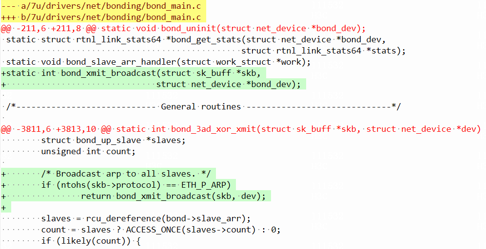
Edit the kernel file named bond_main.c to enable the server to support both ARP and ND.
Verifying the configuration
Verifying the S-MLAG configuration
# Display details of the aggregation groups on Leaf 1. Verify that the member ports in the S-MLAG groups are Selected.
[Leaf1] display link-aggregation verbose Bridge-Aggregation
Loadsharing Type: Shar -- Loadsharing, NonS -- Non-Loadsharing
Port Status: S -- Selected, U -- Unselected, I -- Individual
Port: A -- Auto port, M -- Management port, R -- Reference port
Flags: A -- LACP_Activity, B -- LACP_Timeout, C -- Aggregation,
D -- Synchronization, E -- Collecting, F -- Distributing,
G -- Defaulted, H -- Expired
Aggregate Interface: Bridge-Aggregation1
Creation Mode: Manual
Aggregation Mode: Dynamic
Loadsharing Type: Shar
Management VLANs: None
System ID: 0xc8, 0000-5e00-0101
Local:
Port Status Priority Index Oper-Key Flag
WGE1/0/1(R) S 32768 16385 50001 {ACDEF}
Remote:
Actor Priority Index Oper-Key SystemID Flag
WGE1/0/1 32768 1 1 0x8000, 1451-7eae-dafe {ACDEF}
Aggregate Interface: Bridge-Aggregation2
Creation Mode: Manual
Aggregation Mode: Dynamic
Loadsharing Type: Shar
Management VLANs: None
System ID: 0xc8, 0000-5e00-0101
Local:
Port Status Priority Index Oper-Key Flag
WGE1/0/2(R) S 32768 16386 50002 {ACDEF}
Remote:
Actor Priority Index Oper-Key SystemID Flag
WGE1/0/2 32768 1 1 0x8000, 5cc9-995f-1122 {ACDEF}
# Display details of the aggregation groups on Leaf 2. Verify that the member ports in the S-MLAG groups are Selected.
[Leaf2] display link-aggregation verbose Bridge-Aggregation
Loadsharing Type: Shar -- Loadsharing, NonS -- Non-Loadsharing
Port Status: S -- Selected, U -- Unselected, I -- Individual
Port: A -- Auto port, M -- Management port, R -- Reference port
Flags: A -- LACP_Activity, B -- LACP_Timeout, C -- Aggregation,
D -- Synchronization, E -- Collecting, F -- Distributing,
G -- Defaulted, H -- Expired
Aggregate Interface: Bridge-Aggregation1
Creation Mode: Manual
Aggregation Mode: Dynamic
Loadsharing Type: Shar
Management VLANs: None
System ID: 0xc8, 0000-5e00-0101
Local:
Port Status Priority Index Oper-Key Flag
WGE1/0/1(R) S 32768 32769 50001 {ACDEF}
Remote:
Actor Priority Index Oper-Key SystemID Flag
WGE1/0/1 32768 2 1 0x8000, 1451-7eae-dafe {ACDEF}
Aggregate Interface: Bridge-Aggregation2
Creation Mode: Manual
Aggregation Mode: Dynamic
Loadsharing Type: Shar
Management VLANs: None
System ID: 0xc8, 0000-5e00-0101
Local:
Port Status Priority Index Oper-Key Flag
WGE1/0/2(R) S 32768 32770 50002 {ACDEF}
Remote:
Actor Priority Index Oper-Key SystemID Flag
WGE1/0/2 32768 2 1 0x8000, 5cc9-995f-1122 {ACDEF}
Verifying ARP and ND entry learning
# View the ARP entries learned on the S-MLAG interfaces on Leaf 1. Verify that ARP entries have been learned for the hosts connected to these interfaces.
[Leaf1] display arp interface Bridge-Aggregation 1
Type: S-Static D-Dynamic O-Openflow R-Rule M-Multiport I-Invalid
IP address MAC address VLAN/VSI name Interface Aging Type
100.1.1.22 0010-9400-0002 100 BAGG1 83 D
[Leaf1] display arp interface Bridge-Aggregation 2
Type: S-Static D-Dynamic O-Openflow R-Rule M-Multiport I-Invalid
IP address MAC address VLAN/VSI name Interface Aging Type
100.1.1.33 0010-9400-0003 100 BAGG2 80 D
# View the ND entries learned on the S-MLAG interfaces on Leaf 1. Verify that ND entries have been learned for the hosts connected to these interfaces.
[Leaf 1] display ipv6 neighbors interface Bridge-Aggregation 1
Type: S-Static D-Dynamic O-Openflow R-Rule IS-Invalid static
IPv6 address MAC address VLAN/VSI Interface State T Aging
100::22 0010-9400-0002 100 BAGG1 STALE D 37
[Leaf 1]display ipv6 neighbors interface Bridge-Aggregation 2
Type: S-Static D-Dynamic O-Openflow R-Rule IS-Invalid static
IPv6 address MAC address VLAN/VSI Interface State T Aging
100::33 0010-9400-0003 100 BAGG2 STALE D 40
# View the ARP entries learned on the S-MLAG interfaces on Leaf 2. Verify that the ARP entries are the same as those on Leaf 1.
[Leaf2] display arp interface Bridge-Aggregation 1
Type: S-Static D-Dynamic O-Openflow R-Rule M-Multiport I-Invalid
IP address MAC address VLAN/VSI name Interface Aging Type
100.1.1.22 0010-9400-0002 100 BAGG1 88 D
[Leaf2]display arp interface Bridge-Aggregation 2
Type: S-Static D-Dynamic O-Openflow R-Rule M-Multiport I-Invalid
IP address MAC address VLAN/VSI name Interface Aging Type
100.1.1.33 0010-9400-0003 100 BAGG2 89 D
[Leaf2]
# View the ND entries learned on the S-MLAG interfaces on Leaf 2. Verify that the ND entries are the same as those on Leaf 1.
[Leaf2] display ipv6 neighbors interface Bridge-Aggregation 1
Type: S-Static D-Dynamic O-Openflow R-Rule IS-Invalid static
IPv6 address MAC address VLAN/VSI Interface State T Aging
100::22 0010-9400-0002 100 BAGG1 STALE D 37
[Leaf2]display ipv6 neighbors interface Bridge-Aggregation 2
Type: S-Static D-Dynamic O-Openflow R-Rule IS-Invalid static
IPv6 address MAC address VLAN/VSI Interface State T Aging
100::33 0010-9400-0003 100 BAGG2 STALE D 40
# View the IPv4 routes on Leaf 1. Verify that the host routes have been generated based on the host ARP entries.
[Leaf1] display ip routing-table | include 100.1.1.
100.1.1.0/24 Direct 0 0 100.1.1.1 Vlan100
100.1.1.0/32 Direct 0 0 100.1.1.1 Vlan100
100.1.1.1/32 Direct 0 0 127.0.0.1 InLoop0
100.1.1.22/32 Direct 0 0 100.1.1.22 Vlan100
100.1.1.33/32 Direct 0 0 100.1.1.33 Vlan100
100.1.1.255/32 Direct 0 0 100.1.1.1 Vlan100
# View the IPv6 routes on Leaf 1. Verify that the host routes have been generated based on the host ND entries.
<Leaf1> display ipv6 routing-table 100::22
Summary count : 2
Destination: 100::/56 Protocol : Direct
NextHop : :: Preference: 0
Interface : Vlan100 Cost : 0
Destination: 100::22/128 Protocol : Direct
NextHop : 100::22 Preference: 0
Interface : Vlan100 Cost : 0
<Leaf1> display ipv6 routing-table 100::33
Summary count : 2
Destination: 100::/56 Protocol : Direct
NextHop : :: Preference: 0
Interface : Vlan100 Cost : 0
Destination: 100::33/128 Protocol : Direct
NextHop : 100::33 Preference: 0
Interface : Vlan100 Cost : 0
# View the IPv4 routes on Leaf 2. Verify that the host routes have been generated based on the host ARP entries.
[Leaf2] display ip routing-table | include 100.1.1.
100.1.1.0/24 Direct 0 0 100.1.1.1 Vlan100
100.1.1.0/32 Direct 0 0 100.1.1.1 Vlan100
100.1.1.1/32 Direct 0 0 127.0.0.1 InLoop0
100.1.1.22/32 Direct 0 0 100.1.1.22 Vlan100
100.1.1.33/32 Direct 0 0 100.1.1.33 Vlan100
100.1.1.255/32 Direct 0 0 100.1.1.1 Vlan100
# View the IPv6 routes on Leaf 2. Verify that the host routes have been generated based on the host ND entries.
<Leaf2> display ipv6 routing-table 100::22
Summary count : 2
Destination: 100::/56 Protocol : Direct
NextHop : :: Preference: 0
Interface : Vlan100 Cost : 0
Destination: 100::22/128 Protocol : Direct
NextHop : 100::22 Preference: 0
Interface : Vlan100 Cost : 0
<Leaf2> display ipv6 routing-table 100::33
Summary count : 2
Destination: 100::/56 Protocol : Direct
NextHop : :: Preference: 0
Interface : Vlan100 Cost : 0
Destination: 100::33/128 Protocol : Direct
NextHop : 100::33 Preference: 0
Interface : Vlan100 Cost : 0
Verifying the routes
# Display the IPv4 EBGP state on Leaf 1. Verify that EBGP is successfully established between Leaf 1 and spine devices.
<Leaf1> display bgp peer ipv4
BGP local router ID: 1.1.1.1
Local AS number: 100
Total number of peers: 2 Peers in established state: 2
* - Dynamically created peer
^ - Peer created through link-local address
Peer AS MsgRcvd MsgSent OutQ PrefRcv Up/Down State
101.1.1.2 200 38189 40535 0 5 0091h09m Established
103.1.1.2 200 42648 36483 0 5 0091h09m Established
# Display the IPv6 EBGP state on Leaf 1. Verify that EBGP is successfully established between Leaf 1 and spine devices.
<Leaf1> display bgp peer ipv6
BGP local router ID: 1.1.1.1
Local AS number: 100
Total number of peers: 2 Peers in established state: 2
* - Dynamically created peer
^ - Peer created through link-local address
Peer AS MsgRcvd MsgSent OutQ PrefRcv Up/Down State
101::2 200 35691 43195 0 5 0091h09m Established
103::2 200 43779 34926 0 5 0091h09m Established
# Display the IPv4 EBGP state on Leaf 2. Verify that EBGP is successfully established between Leaf 2 and spine devices.
<Leaf2> display bgp peer ipv4
BGP local router ID: 2.2.2.2
Local AS number: 100
Total number of peers: 2 Peers in established state: 2
* - Dynamically created peer
^ - Peer created through link-local address
Peer AS MsgRcvd MsgSent OutQ PrefRcv Up/Down State
102.1.1.2 200 34024 39283 0 7 0091h35m Established
104.1.1.2 200 43762 50955 0 7 0111h45m Established
# Display the IPv6 EBGP state on Leaf 2. Verify that EBGP is successfully established between Leaf 2 and spine devices.
<Leaf2> display bgp peer ipv6
BGP local router ID: 2.2.2.2
Local AS number: 100
Total number of peers: 2 Peers in established state: 2
* - Dynamically created peer
^ - Peer created through link-local address
Peer AS MsgRcvd MsgSent OutQ PrefRcv Up/Down State
102::2 200 52519 41574 0 7 0110h49m Established
104::2 200 41502 50309 0 7 0111h45m Established
# View the host routes that are generated based on ARP entries and redistributed to BGP on Leaf 1. Both of the two IPv4 routes carry the COMMUNITY attribute 0:100.
<Leaf1> display bgp routing-table ipv4 100.1.1.22
BGP local router ID: 1.1.1.1
Local AS number: 100
Paths: 1 available, 1 best
BGP routing table information of 100.1.1.22/32:
Imported route.
Original nexthop: 100.1.1.22
OutLabel : NULL
Community : <0:100>
RxPathID : 0x0
TxPathID : 0x0
AS-path : (null)
Origin : incomplete
Attribute value : MED 0, pref-val 32768
State : valid, local, best
IP precedence : N/A
QoS local ID : N/A
Traffic index : N/A
Tunnel policy : NULL
Rely tunnel IDs : N/A
<Leaf1> display bgp routing-table ipv4 100.1.1.33
BGP local router ID: 1.1.1.1
Local AS number: 100
Paths: 1 available, 1 best
BGP routing table information of 100.1.1.33/32:
Imported route.
Original nexthop: 100.1.1.33
OutLabel : NULL
Community : <0:100>
RxPathID : 0x0
TxPathID : 0x0
AS-path : (null)
Origin : incomplete
Attribute value : MED 0, pref-val 32768
State : valid, local, best
IP precedence : N/A
QoS local ID : N/A
Traffic index : N/A
Tunnel policy : NULL
Rely tunnel IDs : N/A
# View the host routes that are generated based on ND entries and redistributed to BGP on Leaf 1. Both of the IPv6 routes carry the COMMUNITY attribute 0:100.
[Leaf1] display bgp routing-table ipv6 100::22 128
BGP local router ID: 1.1.1.1
Local AS number: 100
Paths: 1 available, 1 best
BGP routing table information of 100::22/128:
Imported route.
Original nexthop: 100::22
OutLabel : NULL
Community : <0:100>
RxPathID : 0x0
TxPathID : 0x0
AS-path : (null)
Origin : incomplete
Attribute value : MED 0, pref-val 32768
State : valid, local, best
IP precedence : N/A
QoS local ID : N/A
Traffic index : N/A
Tunnel policy : NULL
Rely tunnel IDs : N/A
[Leaf1] display bgp routing-table ipv6 100::33 128
BGP local router ID: 1.1.1.1
Local AS number: 100
Paths: 1 available, 1 best
BGP routing table information of 100::33/128:
Imported route.
Original nexthop: 100::33
OutLabel : NULL
Community : <0:100>
RxPathID : 0x0
TxPathID : 0x0
AS-path : (null)
Origin : incomplete
Attribute value : MED 0, pref-val 32768
State : valid, local, best
IP precedence : N/A
QoS local ID : N/A
Traffic index : N/A
Tunnel policy : NULL
Rely tunnel IDs : N/A
# View the host routes that are generated based on ARP entries and redistributed to BGP on Leaf 2. Both of the two IPv4 routes carry the COMMUNITY attribute 0:100.
<Leaf2> display bgp routing-table ipv4 100.1.1.22
BGP local router ID: 2.2.2.2
Local AS number: 100
Paths: 1 available, 1 best
BGP routing table information of 100.1.1.22/32:
Imported route.
Original nexthop: 100.1.1.22
OutLabel : NULL
Community : <0:100>
RxPathID : 0x0
TxPathID : 0x0
AS-path : (null)
Origin : incomplete
Attribute value : MED 0, pref-val 32768
State : valid, local, best
IP precedence : N/A
QoS local ID : N/A
Traffic index : N/A
Tunnel policy : NULL
Rely tunnel IDs : N/A
<Leaf2> display bgp routing-table ipv4 100.1.1.33
BGP local router ID: 2.2.2.2
Local AS number: 100
Paths: 1 available, 1 best
BGP routing table information of 100.1.1.33/32:
Imported route.
Original nexthop: 100.1.1.33
OutLabel : NULL
Community : <0:100>
RxPathID : 0x0
TxPathID : 0x0
AS-path : (null)
Origin : incomplete
Attribute value : MED 0, pref-val 32768
State : valid, local, best
IP precedence : N/A
QoS local ID : N/A
Traffic index : N/A
Tunnel policy : NULL
Rely tunnel IDs : N/A
# View the host routes that are generated based on ND entries and redistributed to BGP on Leaf 2. Both of the IPv6 routes carry the COMMUNITY attribute 0:100.
[Leaf2] display bgp routing-table ipv6 100::22 128
BGP local router ID: 2.2.2.2
Local AS number: 100
Paths: 1 available, 1 best
BGP routing table information of 100::22/128:
Imported route.
Original nexthop: 100::22
OutLabel : NULL
Community : <0:100>
RxPathID : 0x0
TxPathID : 0x0
AS-path : (null)
Origin : incomplete
Attribute value : MED 0, pref-val 32768
State : valid, local, best
IP precedence : N/A
QoS local ID : N/A
Traffic index : N/A
Tunnel policy : NULL
Rely tunnel IDs : N/A
[Leaf2] display bgp routing-table ipv6 100::33 128
BGP local router ID: 2.2.2.2
Local AS number: 100
Paths: 1 available, 1 best
BGP routing table information of 100::33/128:
Imported route.
Original nexthop: 100::33
OutLabel : NULL
Community : <0:100>
RxPathID : 0x0
TxPathID : 0x0
AS-path : (null)
Origin : incomplete
Attribute value : MED 0, pref-val 32768
State : valid, local, best
IP precedence : N/A
QoS local ID : N/A
Traffic index : N/A
Tunnel policy : NULL
Rely tunnel IDs : N/A
# View the IPv4 routes on Spine 1. Verify that the routes advertised by leaf devices form ECMP routes.
[Spine1] display ip routing-table protocol bgp
Summary count : 4
BGP Routing table status : <Active>
Summary count : 4
Destination/Mask Proto Pre Cost NextHop Interface
100.1.1.22/32 BGP 255 0 101.1.1.1 HGE1/0/22
102.1.1.1 HGE1/0/21
100.1.1.33/32 BGP 255 0 101.1.1.1 HGE1/0/22
102.1.1.1 HGE1/0/21
BGP Routing table status : <Inactive>
Summary count : 0
# View the IPv6 routes on Spine 1. Verify that the routes advertised by leaf devices form ECMP routes.
[Spine1] display ipv6 routing-table protocol bgp4+
Summary count : 4
BGP4+ Routing table status : <Active>
Summary count : 4
Destination: 100::22/128 Protocol : BGP4+
NextHop : 101::1 Preference: 255
Interface : HGE1/0/22 Cost : 0
Destination: 100::22/128 Protocol : BGP4+
NextHop : 102::1 Preference: 255
Interface : HGE1/0/21 Cost : 0
Destination: 100::33/128 Protocol : BGP4+
NextHop : 101::1 Preference: 255
Interface : HGE1/0/22 Cost : 0
Destination: 100::33/128 Protocol : BGP4+
NextHop : 102::1 Preference: 255
Interface : HGE1/0/21 Cost : 0
BGP4+ Routing table status : <Inactive>
Summary count : 0
# View the IPv4 routes on Spine 2. Verify that the routes advertised by leaf devices form ECMP routes.
[Spine2] display ip routing-table protocol bgp
Summary count : 4
BGP Routing table status : <Active>
Summary count : 4
Destination/Mask Proto Pre Cost NextHop Interface
100.1.1.22/32 BGP 255 0 103.1.1.1 HGE1/0/22
104.1.1.1 HGE1/0/21
100.1.1.33/32 BGP 255 0 103.1.1.1 HGE1/0/22
104.1.1.1 HGE1/0/21
BGP Routing table status : <Inactive>
Summary count : 0
# View the IPv6 routes on Spine 2. Verify that the routes advertised by leaf devices form ECMP routes.
[Spine2] display ipv6 routing-table protocol bgp4+
Summary count : 4
BGP4+ Routing table status : <Active>
Summary count : 4
Destination: 100::22/128 Protocol : BGP4+
NextHop : 103::1 Preference: 255
Interface : HGE1/0/22 Cost : 0
Destination: 100::22/128 Protocol : BGP4+
NextHop : 104::1 Preference: 255
Interface : HGE1/0/21 Cost : 0
Destination: 100::33/128 Protocol : BGP4+
NextHop : 103::1 Preference: 255
Interface : HGE1/0/22 Cost : 0
Destination: 100::33/128 Protocol : BGP4+
NextHop : 104::1 Preference: 255
Interface : HGE1/0/21 Cost : 0
BGP4+ Routing table status : <Inactive>
Summary count : 0
# View the BGP route information on Spine 1. Verify that the AS_PATH attributes of the routes are changed to the local AS.
[Spine1] display bgp routing-table ipv4
Total number of routes: 4
BGP local router ID is 3.3.3.3
Status codes: * - valid, > - best, d - dampened, h - history
s - suppressed, S - stale, i - internal, e - external
a - additional-path
Origin: i - IGP, e - EGP, ? - incomplete
Network NextHop MED LocPrf PrefVal Path/Ogn
* >e 100.1.1.22/32 101.1.1.1 0 0 200?
* >e 102.1.1.1 0 0 200?
* >e 100.1.1.33/32 101.1.1.1 0 0 200?
* >e 102.1.1.1 0 0 200?
[Spine1] display bgp routing-table ipv6
Total number of routes: 4
BGP local router ID is 3.3.3.3
Status codes: * - valid, > - best, d - dampened, h - history
s - suppressed, S - stale, i - internal, e - external
a - additional-path
Origin: i - IGP, e - EGP, ? - incomplete
* >e Network : 100::22 PrefixLen : 128
NextHop : 101::1 LocPrf :
PrefVal : 0 OutLabel : NULL
MED : 0
Path/Ogn: 200?
* >e Network : 100::22 PrefixLen : 128
NextHop : 102::1 LocPrf :
PrefVal : 0 OutLabel : NULL
MED : 0
Path/Ogn: 200?
* >e Network : 100::33 PrefixLen : 128
NextHop : 101::1 LocPrf :
PrefVal : 0 OutLabel : NULL
MED : 0
Path/Ogn: 200?
* >e Network : 100::33 PrefixLen : 128
NextHop : 102::1 LocPrf :
PrefVal : 0 OutLabel : NULL
MED : 0
Path/Ogn: 200?
# View the BGP route information on Spine 2. Verify that the AS_PATH attributes of the routes are changed to the local AS.
[Spine2] display bgp routing-table ipv4
Total number of routes: 4
BGP local router ID is 4.4.4.4
Status codes: * - valid, > - best, d - dampened, h - history
s - suppressed, S - stale, i - internal, e - external
a - additional-path
Origin: i - IGP, e - EGP, ? - incomplete
Network NextHop MED LocPrf PrefVal Path/Ogn
* >e 100.1.1.22/32 103.1.1.1 0 0 200?
* >e 104.1.1.1 0 0 200?
* >e 100.1.1.33/32 103.1.1.1 0 0 200?
* >e 104.1.1.1 0 0 200?
[Spine2] display bgp routing-table ipv6
Total number of routes: 4
BGP local router ID is 4.4.4.4
Status codes: * - valid, > - best, d - dampened, h - history
s - suppressed, S - stale, i - internal, e - external
a - additional-path
Origin: i - IGP, e - EGP, ? - incomplete
* >e Network : 100::22 PrefixLen : 128
NextHop : 103::1 LocPrf :
PrefVal : 0 OutLabel : NULL
MED : 0
Path/Ogn: 200?
* >e Network : 100::22 PrefixLen : 128
NextHop : 104::1 LocPrf :
PrefVal : 0 OutLabel : NULL
MED : 0
Path/Ogn: 200?
* >e Network : 100::33 PrefixLen : 128
NextHop : 103::1 LocPrf :
PrefVal : 0 OutLabel : NULL
MED : 0
Path/Ogn: 200?
* >e Network : 100::33 PrefixLen : 128
NextHop : 104::1 LocPrf :
PrefVal : 0 OutLabel : NULL
MED : 0
Path/Ogn: 200?
# Verify the SoO attribute configuration. To view the route advertisement paths clearly, you must shut down the interface connecting Leaf 2 to Server 1 and the interface connecting Leaf 1 to Spine 2. In this case, the advertisement path of the host route for Server 1 is Leaf 1->Spine 1->Leaf 2->Spine 2. Leaf 2 receives the host route for Server 1 advertised by Spine 1 and checks that the route carries the same SoO attribute. Therefore, Leaf 2 does not advertise the host route for Server 1 to Spine 2.
[Leaf2] display bgp routing-table ipv4 100.1.1.22 32
BGP local router ID: 2.2.2.2
Local AS number: 100
Paths: 1 available, 1 best
BGP routing table information of 100.1.1.22/32:
From : 102.1.1.2 (3.3.3.3)
Rely nexthop : 102.1.1.2
Original nexthop: 102.1.1.2
OutLabel : NULL
Ext-Community : <SOO: 0:100>
RxPathID : 0x0
TxPathID : 0x0
AS-path : 200 200
Origin : incomplete
Attribute value : pref-val 0
State : valid, external, best
IP precedence : N/A
QoS local ID : N/A
Traffic index : N/A
Tunnel policy : NULL
Rely tunnel IDs : N/A
The output shows that the IPv4 host route for Server 1 received on Leaf 2 carries the SoO attribute.
[Leaf2] display bgp routing-table ipv6 100::22 128
BGP local router ID: 2.2.2.2
Local AS number: 100
Paths: 1 available, 1 best
BGP routing table information of 100::22/128:
Original nexthop: 100::22
OutLabel : NULL
Ext-Community : <SOO: 0:100>
RxPathID : 0x0
TxPathID : 0x0
AS-path : 200 200
Origin : incomplete
Attribute value : pref-val 0
State : valid, external, best
IP precedence : N/A
QoS local ID : N/A
Traffic index : N/A
Tunnel policy : NULL
Rely tunnel IDs : N/A
The output shows that the IPv6 host route for Server 1 received on Leaf 2 carries the SoO attribute.
[Leaf2] display bgp routing-table ipv4 peer 102.1.1.2 advertised-routes
Total number of routes: 1
BGP local router ID is 2.2.2.2
Status codes: * - valid, > - best, d - dampened, h - history
s - suppressed, S - stale, i - internal, e - external
a - additional-path
Origin: i - IGP, e - EGP, ? - incomplete
Network NextHop MED LocPrf Path/Ogn
* > 100.1.1.33/32 100.1.1.33 0 100?
The output shows that the IPv4 host route for Server 1 with the SoO attribute 0:100 is not advertised by Leaf 2 to Spine 2.
[Leaf2] display bgp routing-table ipv6 peer 102::2 advertised-routes
Total number of routes: 1
BGP local router ID is 2.2.2.2
Status codes: * - valid, > - best, d - dampened, h - history
s - suppressed, S - stale, i - internal, e - external
a - additional-path
Origin: i - IGP, e - EGP, ? - incomplete
* > Network : 100::33 PrefixLen : 128
NextHop : 100::33 LocPrf :
MED : 0 OutLabel : NULL
The output shows that the IPv6 host route for Server 1 with the SoO attribute 0:100 is not advertised by Leaf 2 to Spine 2.
Verifying the ARP anti-leakage configuration
# Display the QoS policy applied in the inbound direction globally on Leaf 1. Verify that the policy that prevents leaking ARP entries between leaf devices is successfully applied.
[Leaf1] display qos policy global inbound
Direction: Inbound
Policy: hw-forwarding
Classifier: Arp-Forwarding
Operator: AND
Rule(s) :
If-match source-mac 0000-5e00-0101
If-match acl mac 4000
Behavior: Forwarding
Filter enable: Permit
Classifier: Arp-No-Forwarding
Operator: AND
Rule(s) :
If-match acl mac 4000
Behavior: No-Forwarding
Filter enable: Deny
# Display the QoS policy applied in the inbound direction globally on Leaf 2. Verify that the policy that prevents leaking ARP entries between leaf devices is successfully applied.
[Leaf2] display qos policy global inbound
Direction: Inbound
Policy: hw-forwarding
Classifier: Arp-Forwarding
Operator: AND
Rule(s) :
If-match source-mac 0000-5e00-0101
If-match acl mac 4000
Behavior: Forwarding
Filter enable: Permit
Classifier: Arp-No-Forwarding
Operator: AND
Rule(s) :
If-match acl mac 4000
Behavior: No-Forwarding
Filter enable: Deny
# Display the ARP information on Server 1. Verify that Server 1 does not learn the MAC address of Server 2.
[root@SER1 ~]# arp -n
Address HWtype HWaddress Flags Mask Iface
100.1.1.1 ether 00:00:5e:00:01:01 C eth1
100.1.1.1 ether 00:00:5e:00:01:01 C eth2
[root@SER1 ~]# ip -6 nei
100::1 dev eth1 lladdr 00:00:5e:00:01:01 router STALE
100::1 dev eth2 lladdr 00:00:5e:00:01:01 router STALE
# Display the ARP information on Server 2. Verify that Server 2 does not learn the MAC address of Server 1.
[root@SER2 ~]# arp -n
Address HWtype HWaddress Flags Mask Iface
100.1.1.1 ether 00:00:5e:00:01:01 C eth1
100.1.1.1 ether 00:00:5e:00:01:01 C eth2
[root@@SER2 ~]# ip -6 nei
100::1 dev eth1 lladdr 00:00:5e:00:01:01 router STALE
100::1 dev eth2 lladdr 00:00:5e:00:01:01 router STALE
Verifying the monitor link configuration
# Display the monitor link group information on Leaf 1. Verify that the monitor link group is up.
[Leaf1] display monitor-link group 1
Monitor link group 1 information:
Group status : UP
Downlink up-delay: 120(s)
Last-up-time : 22:27:50 2001/01/28
Last-down-time : -
Up-port-threshold: 1
Member Role Status
--------------------------------------------------------
HGE1/0/25 UPLINK UP
HGE1/0/26 UPLINK UP
WGE1/0/1 DOWNLINK UP
WGE1/0/2 DOWNLINK UP
# Display the monitor link group information on Leaf 2. Verify that the monitor link group is up.
[Leaf2] display monitor-link group 1
Monitor link group 1 information:
Group status : UP
Downlink up-delay: 120(s)
Last-up-time : 22:27:50 2001/01/28
Last-down-time : -
Up-port-threshold: 1
Member Role Status
--------------------------------------------------------
HGE1/0/25 UPLINK UP
HGE1/0/26 UPLINK UP
WGE1/0/1 DOWNLINK UP
WGE1/0/2 DOWNLINK UP
Device isolation operation guides
When a device fails or the software of a device is upgraded, you must isolate the device to avoid or reduce the service interruption time.
Leaf device isolation operation guide
Operation procedure
To isolate a leaf device, first isolate the downlink interfaces and then isolate the uplink interfaces to ensure that all traffic does not pass through the device.
After the troubleshooting or software upgrade is completed, first unisolate the uplink interfaces, and then unisolate the downlink interfaces after the BGP routes are learned.
For the isolation and unisolation convergence time, see “Failure and recovery convergence.”
Isolating leaf devices
# Shut down all S-MLAG link interfaces.
[Leaf1] interface range twenty-fivegige 1/0/1 twenty-fivegige 1/0/2
[Leaf1-if-range] shutdown
[Leaf1-if-range] quit
# Shut down all uplink interfaces.
[Leaf1] interface range hundredgige 1/0/25 hundredgige 1/0/26
[Leaf1-if-range] shutdown
[Leaf1-if-range] quit
Unisolating leaf devices
# Bring up all uplink interfaces to restore the uplinks.
[Leaf1] interface range hundredgige 1/0/25 hundredgige 1/0/26
[Leaf1-if-range] undo shutdown
[Leaf1-if-range] quit
# Bring up all S-MLAG link interfaces to restore the downlinks.
[Leaf1] interface range twenty-fivegige 1/0/1 twenty-fivegige 1/0/2
[Leaf1-if-range] undo shutdown
[Leaf1-if-range] quit
Spine device isolation operation guide
Operation procedure
To isolate the spine devices, you must configure routing policies to redirect traffic. First configure an export routing policy that does not advertise routes out, and make sure all traffic does not pass through the isolated device. Then, configure an import routing policy that does not receive routes. At last, execute the peer ignore command to disable BGP session establishment with the uplink devices and leaf devices. In this way, the device is completely isolated.
After the troubleshooting or software upgrade is completed, first delete the peer ignore command configuration to restore the EBGP neighbor relationship with the uplink devices and leaf devices. Then, delete the import routing policy. At last, delete the export routing policy to switch traffic back to the device.
For the isolation and unisolation convergence time, see “Failure and recovery convergence.”
Isolating the spine devices
# Configure routing policy deny to deny all routes.
[Spine1] route-policy deny deny node 0
[Spine1-route-policy-deny-0]
[Spine1-route-policy-deny-0] quit
# Apply routing policy deny to routes outgoing to peers CORE and COREv6.
[Spine1] bgp 200
[Spine1-bgp-default] address-family ipv4 unicast
[Spine1-bgp-default-ipv4] peer CORE route-policy deny export
[Spine1-bgp-default-ipv4] quit
[Spine1-bgp-default] address-family ipv6 unicast
[Spine1-bgp-default-ipv6] peer COREv6 route-policy deny export
[Spine1-bgp-default-ipv6] quit
# Apply routing policy deny to routes outgoing to peers LEAF and LEAFv6.
[Spine1-bgp-default-ipv4] peer LEAF route-policy deny export
[Spine1-bgp-default-ipv4] quit
[Spine1-bgp-default] address-family ipv6 unicast
[Spine1-bgp-default-ipv6] peer LEAFv6 route-policy deny export
[Spine1-bgp-default-ipv6] quit
# Apply routing policy deny to routes incoming from peers CORE and COREv6.
[Spine1-bgp-default-ipv4] peer CORE route-policy deny import
[Spine1-bgp-default-ipv4] quit
[Spine1-bgp-default] address-family ipv6 unicast
[Spine1-bgp-default-ipv6] peer COREv6 route-policy deny import
[Spine1-bgp-default-ipv6] quit
# Apply routing policy deny to routes incoming from peers LEAF and LEAFv6.
[Spine1-bgp-default-ipv4] peer LEAF route-policy deny import
[Spine1-bgp-default-ipv4] quit
[Spine1-bgp-default] address-family ipv6 unicast
[Spine1-bgp-default-ipv6] peer LEAFv6 route-policy deny import
[Spine1-bgp-default-ipv6] quit
# Disable BGP session establishment with uplink devices and leaf devices.
[Spine1-bgp-default] peer CORE ignore
[Spine1-bgp-default] peer COREv6 ignore
[Spine1-bgp-default] peer LEAF ignore
[Spine1-bgp-default] peer LEAFv6 ignore
# Shut down all interfaces. (Details not shown.)
Unisolating spine devices
# Bring up all interfaces. (Details not shown.)
# Execute the undo form of the peer ignore command to enable BGP session establishment with uplink devices and leaf devices.
[Spine1] bgp 200
[Spine1-bgp-default] undo peer CORE ignore
[Spine1-bgp-default] undo peer CORE ignore
[Spine1-bgp-default] undo peer COREv6 ignore
[Spine1-bgp-default] undo peer LEAF ignore
[Spine1-bgp-default] undo peer LEAFv6 ignore
# Restore the original import routing policy on the leaf devices. (In the isolation procedure, the routing policy AS_Replace is overwritten.)
[Spine1-bgp-default] address-family ipv4 unicast
[Spine1-bgp-default-ipv4] peer LEAF route-policy AS_Replace import
[Spine1-bgp-default-ipv4] quit
[Spine1-bgp-default] address-family ipv6 unicast
[Spine1-bgp-default-ipv6] peer LEAFv6 route-policy AS_Replace import
[Spine1-bgp-default-ipv6] quit
# Delete routing policy deny from routes incoming from peers CORE and COREv6.
[Spine1-bgp-default] address-family ipv4 unicast
[Spine1-bgp-default-ipv4] undo peer CORE route-policy deny import
[Spine1-bgp-default-ipv4] quit
[Spine1-bgp-default] address-family ipv6 unicast
[Spine1-bgp-default-ipv6] undo peer COREv6 route-policy deny import
[Spine1-bgp-default-ipv6] quit
# Delete routing policy deny from routes outgoing to peers LEAF and LEAFv6.
[Spine1-bgp-default] address-family ipv4 unicast
[Spine1-bgp-default-ipv4] undo peer LEAF route-policy deny export
[Spine1-bgp-default-ipv4] quit
[Spine1-bgp-default] address-family ipv6 unicast
[Spine1-bgp-default-ipv6] undo peer LEAFv6 route-policy deny export
[Spine1-bgp-default-ipv6] quit
# Delete routing policy deny from routes outgoing to peers CORE and COREv6.
[Spine1-bgp-default] address-family ipv4 unicast
[Spine1-bgp-default-ipv4] undo peer CORE route-policy deny export
[Spine1-bgp-default-ipv4] quit
[Spine1-bgp-default] address-family ipv6 unicast
[Spine1-bgp-default-ipv6] undo peer COREv6 route-policy deny export
[Spine1-bgp-default-ipv6] quit
[Spine1-bgp-default] quit
# Delete routing policy deny from routes incoming from peers LEAF and LEAFv6.
[Spine1-bgp-default-ipv4] undo peer LEAF route-policy deny import
[Spine1-bgp-default-ipv4] quit
[Spine1-bgp-default] address-family ipv6 unicast
[Spine1-bgp-default-ipv6] undo peer LEAFv6 route-policy deny import
[Spine1-bgp-default-ipv6] quit
# Delete routing policy deny.
[Spine1] undo route-policy deny deny node 0
Failure and recovery convergence
Traffic convergence
The failures are as shown in Table 5Figure 8. The convergence time on an S6850 device running version R6635 is as shown in Table 5.
Table 5 Failure and recovery convergence time
|
Device |
Failure type |
Traffic interruption time |
|
Leaf |
Single point of failure on member link 1 |
73 ms |
|
Recovery for single point of failure on member link 1 |
5 ms |
|
|
Single point of failure on uplink ECMP link 3 |
50 ms |
|
|
Recovery for single point of failure on uplink ECMP link 3 |
3 ms |
|
|
Leaf 1 device failure |
78 ms |
|
|
Failure recovery on leaf 1 |
6 ms |
|
|
Leaf 1 isolation (shutting down all interfaces connecting to servers) |
72 ms |
|
|
Failure recovery on leaf 1 |
7 ms |
|
|
Spine |
Failure on spine 1 |
124 ms |
|
Failure recovery on spine 1 |
0 ms |
|
|
Isolation |
0 ms |
|
|
Unisolation |
0 ms |
Figure 8 Failure and recovery convergence diagram