| Title | Size | Downloads |
|---|---|---|
| H3C CAS CVM Disaster Recovery Configuration Guide-5W101-book.pdf | 4.19 MB |
- Table of Contents
- Related Documents
-
H3C CAS
Disaster Recovery Configuration Guide
Document version: 5W101-20211119
Copyright © 2021 New H3C Technologies Co., Ltd. All rights reserved.
No part of this manual may be reproduced or transmitted in any form or by any means without prior written consent of New H3C Technologies Co., Ltd.
Except for the trademarks of New H3C Technologies Co., Ltd., any trademarks that may be mentioned in this document are the property of their respective owners.
The information in this document is subject to change without notice.
Contents
Key metrics for disaster recovery performance measurement
About CAS disaster recovery management
Storage replication-based disaster recovery
Disaster recovery preparations
Disk backup-based disaster recovery
Disaster recovery preparations
Configuring storage replication-based disaster recovery
Configuring storage arrays and DRM
Preparing the storage environment
Configuring disk backup-based disaster recovery
Downloading a disaster recovery client
Installing the disaster recovery client on VMs
Specifying disaster recovery storage nodes
Configuring a storage pool as a storage medium on a disaster recovery storage node
Changing the network type of a vSwitch from backup to disaster recovery
Configuring a protection group
Configuring the protected site
About disaster recovery
Disaster recovery recovers data and resumes service operations for information systems from faults or breakdowns caused by natural disasters and infrastructure failures such as fires, floods, earthquakes, power outages, and network egress failures.
Typically, a disaster recovery system contains two or more identical service systems deployed on geographically dispersed sites. The disaster recovery system monitors the service systems and maintains data consistency among them. When one service system fails, its services fail over to another site to ensure service continuity.
Key metrics for disaster recovery performance measurement
The following metrics are used for measuring the performance of a disaster recovery system:
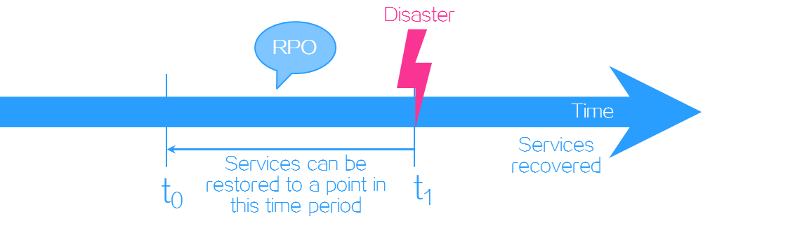
· Recovery point objective (RPO)—The maximum acceptable amount of data loss measured in time. It refers to a period of time in which services must be restored and recovered. RPO is used to measure the data loss caused by a disaster and to evaluate the data backup capability of a disaster recovery system. Typically RPO depends on how data is replicated. Synchronous replication can guarantee an RPO of zero, which indicates no data loss. In asynchronous replication, RPO is determined by the replication cycle.
Figure 1 RPO
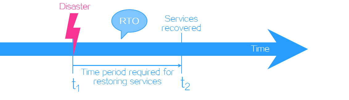
· Recovery time objective (RTO)—The maximum tolerable length of time that a service system can be down after a failure or disaster. It defines how long it takes to restore services to running state. RTO is used to measure the data restoration capability of a disaster recovery system. It is determined by the service restoration procedure in disaster recovery. The more automated the restoration steps, the smaller the RTO.
Figure 2 RTO
Types of disaster recovery
Based on the level of protection, the following types of disaster recovery are available:
· Data-level disaster recovery—Replicates data among disaster recovery sites at different locations to avoid data loss or damage in the event of a disaster. To one site, the other sites are remote data backup centers.
· Application-level disaster recovery—Maintains an identical application system on a backup site for failed important applications to fail over to the backup site after a disaster as soon as possible. It enables application systems to offer complete, reliable, and secure services to users.
Data backup
Data backup copies all or some data sets of an application from a host disk or storage array to another storage medium to prevent misoperations or failures from causing data loss. CAS CVM relies on array-based replication and continuous data protection (CDP) to back up data.
Array-based replication
Array-based replication can be performed synchronously or asynchronously.
Synchronous replication
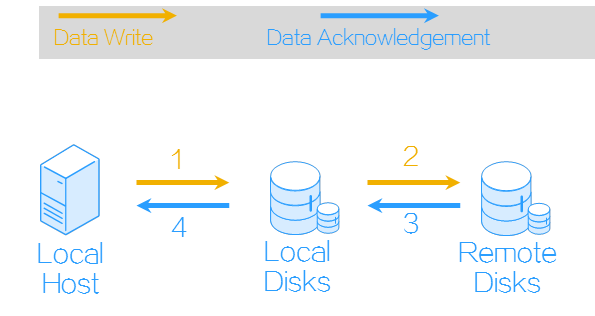
Synchronous replication ensures data consistency between the storage volumes in a replication pair. In synchronous replication, each IO operation releases resources only after both the local and remote volumes in a replication pair return write operation completion. Synchronous replication provides the highest level of data integrity at the cost of decreased performance caused by data transmission latency, and it requires the round trip delay between source and destination arrays to be short. Typically, synchronous replication is used for short-distance replication (10 to 100 km, or 6.21 to 62.13 miles) in scenarios that require strict data consistency and near-zero data loss, such as internal systems of banks.
Figure 3 Synchronous replication
Asynchronous replication
Asynchronous replication is performed periodically and thus cannot ensure data consistency between volumes in a replication pair. In asynchronous replication, a local volume creates a snapshot after it finishes a write operation and copies the snapshot to a remote volume. Asynchronous replication offers high performance but does not guarantee zero data loss because source and destination volumes might have inconsistent data. Asynchronous replication does not require high bandwidth or short transmission distance, which makes it suitable for systems that require high performance, have light write loads, and does not require high array IOPS performance or short delay, such as databases and file systems.
Figure 4 Asynchronous replication

CDP
CDP backs up production data on a system to a target repository every time a change is made. By capturing and tracking data modifications, CDP maintains a continuous journal of data changes and makes it possible to restore a system to any previous point in time. CDP depends on agent software to monitor IO changes.
About CAS disaster recovery management
Based on array-based replication and CDP, CAS CVM provides both storage replication-based disaster recovery and disk backup-based disaster recovery. The following information will describe the application scenarios and mechanisms of the two applications and the disaster recovery configuration procedure.
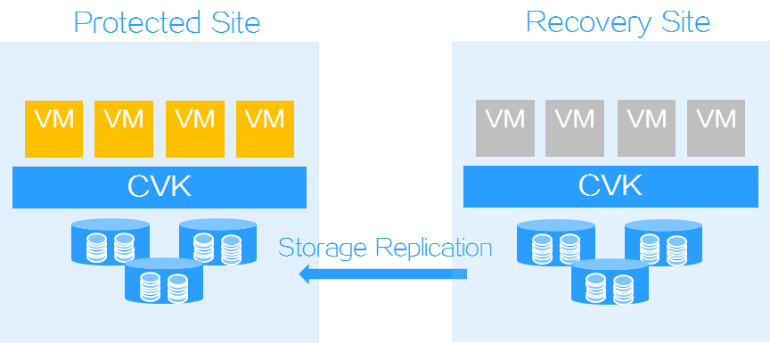
Storage replication-based disaster recovery
Application scenarios
Storage replication-based disaster recovery is applicable to data centers in homogeneous clouds where the same CAS CVM version is deployed on the protected and recovery sites and the protected objects are VMs. It can reduce RPO and RTO to minutes and copy data between storage arrays through synchronous or asynchronous replication.
Configuration environment
· CAS edition—CAS Enhanced Enterprise Edition with DRM licensed, E0536 and later. Install the SRM license at the protection site (production site).
· Storage—Use storage resources that meet the following requirements:
¡ Storage automation support—MacroSAN or HPE 3PAR.
¡ 3PAR version—3.2.2.709 or later, with support for remote copy and active-active replication (licensed by using Peer Persistence License). The storage servers on the protected and recovery sites must use the same 3PAR version.
¡ HPE storage array—With support for remote replication.
Mechanisms
CAS CVM ensures data consistency and service continuity as follows:
· At the storage level, DRM backs up data through remote replication between storage arrays.
· At the service level, DRM copies configuration of protected VMs from a protected site to a recovery site in each protection group.
When the protected site fails, DRM restores protected VMs on the recovery site by using the data backed up at the storage and service levels based on a recovery plan.
Figure 5 Storage replication-based disaster recovery procedure
Features
Two replication modes
Array-based replication copies data of protected VMs at the storage level to reduce the impact of disaster recovery services on production server performance. You can choose synchronous or asynchronous replication based on your expected RPO and RTO and scenarios.
Support for various disaster recovery scenarios
DRM allows you to simulate disaster recovery without interrupting running services. This mechanism can help you achieve the expected recovery target and decrease RTO. You also can fail over services from a recovery site to a protected site, run recovery as scheduled for maintenance purposes, and fail over services to the recovery site in the event of protected site failure.
One-stop disaster recovery solution
DRM offers unified management of the protected and recovery sites. It can synchronize the disaster recovery configuration on the recovery site with the protected site. You do not need to configure DRM on multiple consoles.
DRM supports one-to-many backup. You can set up multiple recovery sites for a protected site.
Support for a wide range of storage devices
You can use storage arrays from any vendors, as long as they support remote replication and snapshots. With storage arrays that support storage replication adapters (SRAs), DRM can achieve automatic data replication and service failover. For storage arrays that do not support SRAs, you need manually synchronize storage services during service failover.
Configuration procedure
Figure 6 shows the general configuration procedures for storage replication-based disaster recovery. For more information about the configuration procedures, see "Disaster recovery preparations," "DRM tasks," and "Disaster recovery scenarios."
Figure 6 Configuration procedure for storage replication-based disaster recovery

Disaster recovery preparations
Before you configure storage replication-based disaster recovery, perform the following tasks:
1. Configure remote replication and volume mappings for storage arrays.
2. Attach volumes to hosts on CAS.
DRM tasks
Configuring sites
On either the protected site or recovery site, configure a local site and a remote site on CAS. You must add storage array managers when creating sites if storage arrays support SRAs.
Configuring a protection group
A protection group protects a set of VMs or bare metal servers. A protection group protects a set of VMs that use the same storage pool (corresponds to one or multiple LUNs on a storage array) based on a protection policy. It replicates the VM data stored on a LUN on the local storage array to a LUN on a remote storage array through array-based replication.
When you configure a storage replication protection group, you must specify the protected and recovery sites, original and target host pools, and resource mappings. Resource mapping relations associate the resources used by the protected VMs on the protected site with the sources on the recovery site. When VMs are recovered on the recovery site, the resources they use are automatically replaced with the resources of the recovery site. You can configure vSwitch, port profile, and storage (LUN) mappings.
After you create a protection group, CAS automatically synchronizes VM data. In the homogeneous clouds scenario, you also can manually synchronize VM data before failover.
Configuring a recovery plan
DRM allows you to customize disaster recovery settings by creating recovery plans on a per-protection group basis. When a recovery plan is executed, DRM automatically restores protected objects on the recovery site.
Disaster recovery scenarios
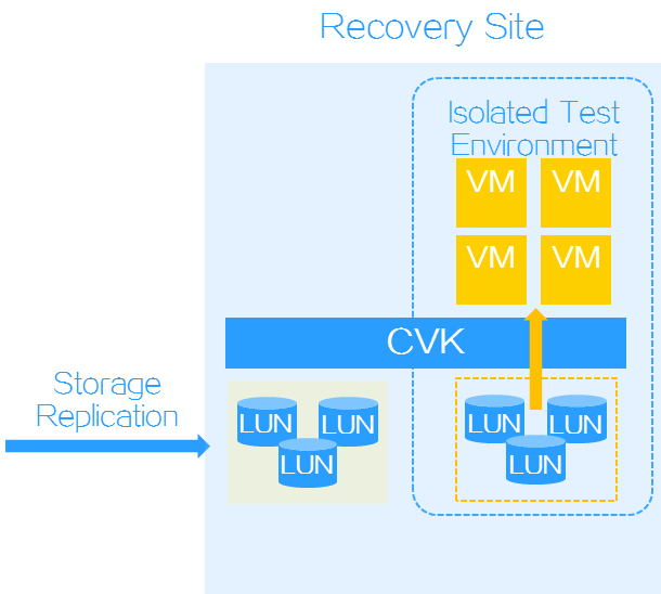
Recovery plan test
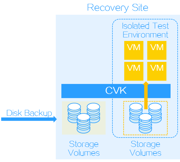
DRM allows you to test whether a recovery plan operates correctly by failing over protected objects based on the recovery plan to an isolated test environment on the recovery site without interrupting services. You must manually finish a recovery plan test to clear the environment and restore the state of the recovery plan to Ready.
In storage replication-based disaster recovery, VMs are attached to the LUNs on the recovery site.
Figure 7 Recovery plan test for storage replication-based disaster recovery
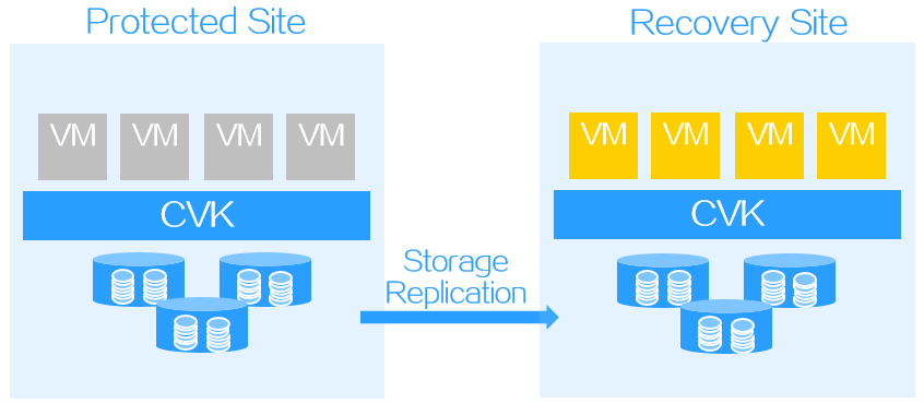
Scheduled recovery
A scheduled recovery resumes protected objects on the recovery site for regular maintenance of the protected site.
Figure 8 Scheduled recovery
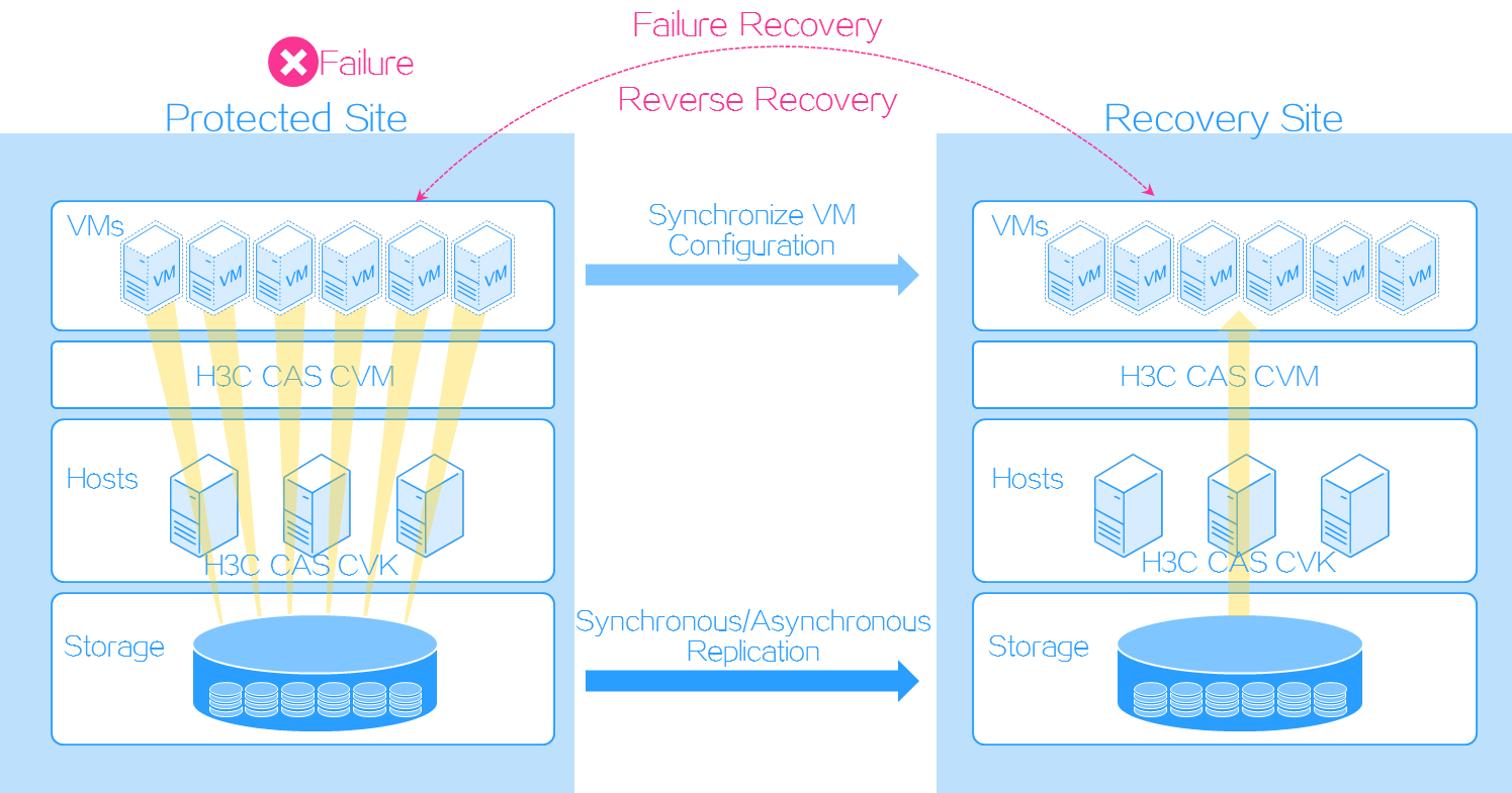
Failure recovery
Failure recovery restores protected objects on the recovery site based on a recover plan to reduce the service interruption time when the protected site fails.
For storage replication-based disaster recovery, the RPO is determined by the replication mode.
· For asynchronous replication, the RPO is not 0 when failover recovery is executed.
· For synchronous replication, the RPO is 0 when failover recovery is executed.
Figure 9 Failure recovery

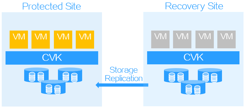
Reverse recovery
Storage replication-based disaster recovery can fall back VMs from a recovery site to a protected site when the protected site recovers from failure.
Figure 10 Reverse recovery
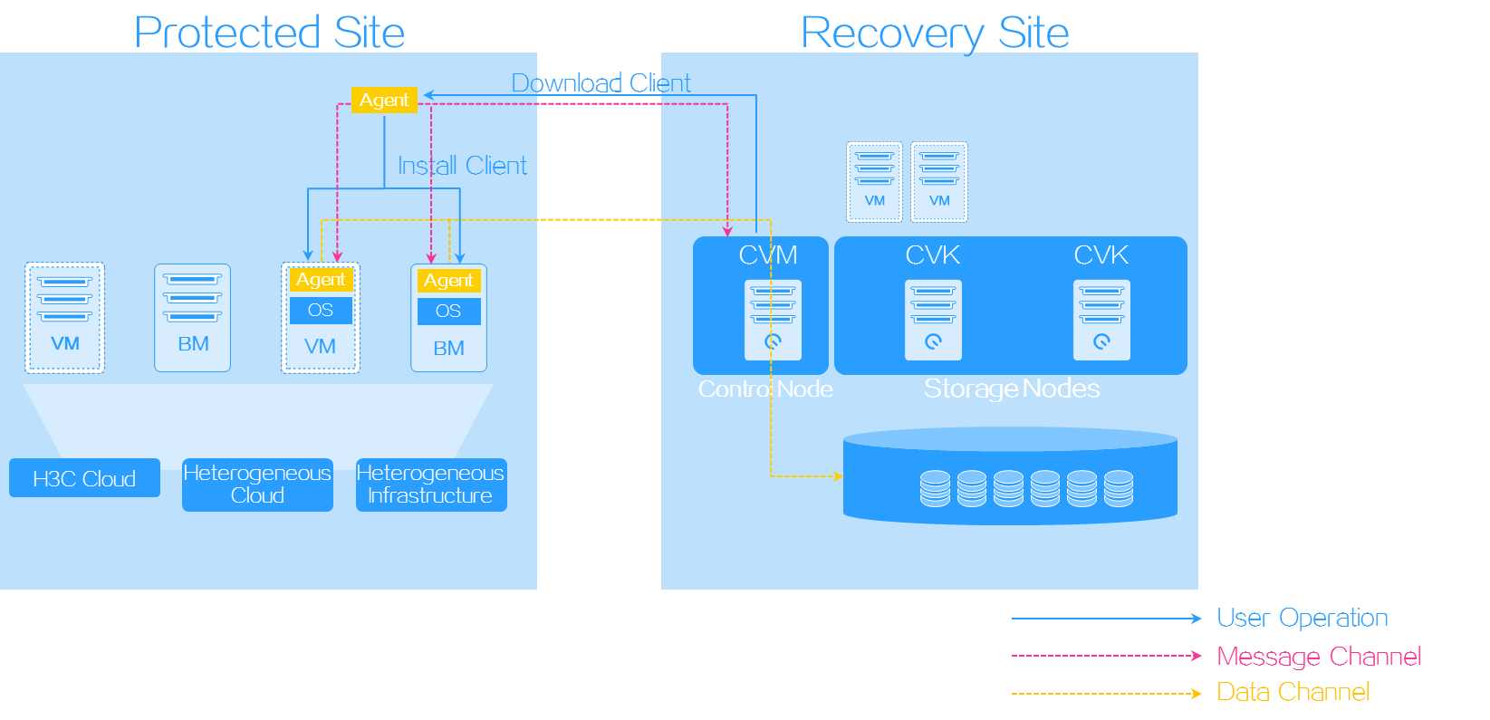
Disk backup-based disaster recovery
Disk backup-based disaster recovery uses CDP to replicate operating system data for disaster recovery. DRM obtains host information and captures data block changes from the CDP agents installed on the hosts where protected objects reside, and transmits incremental data to the storage nodes on the recovery site.
With the snapshot chain and real-time synchronization mechanisms, data can be backed up and synchronized in seconds to satisfy the requirements of high-performance RPO data recovery. Disk backup-based disaster recovery supports backing up services of multiple cloud platforms with different infrastructure on one recovery site. It can be used in all application scenarios of DRM.
Application scenarios
Disk backup-based disaster recovery is applicable to the following scenarios:
· Homogeneous clouds—The same CAS CVM version is deployed on the protected and recovery sites, and the protected objects are VMs.
· Heterogeneous clouds—CAS CVM is deployed on the recovery site, and one of the following conditions exists on the protected site:
¡ The protected VMs are running on a non-CAS cloud platform.
¡ The CAS CVM version of the protected site is lower than that of the recovery site.
¡ The protected objects are bare metal servers.
· Hybrid infrastructure—CAS CVM is deployed on the recovery site, and the protected site accommodates both VMs and bare metal servers.
Disk backup-based disaster recovery can reduce RPO and RTO to minutes.
Configuration environment
· Storage—Not requirements.
· Projected site—x86 cloud platforms, or physical servers.
· Recovery site—CAS Enhanced Enterprise Edition with DRM licensed, E0536 and later.
· Operating system of protected nodes—Windows Server or Linux. For more information, see "OS compatibility matrix for disk backup-based disaster recovery."
Mechanisms
DRM protects VMs or bare metal servers (or referred to as production nodes) installed with the disaster recovery client. The real-time disk replication feature of the disaster recovery client copies data of protected objects by operating system to the recovery site for DRM to restore the protected objects as VMs.
Figure 11 Disk backup-based disaster recovery procedure
Configuration procedure
Figure 12 shows the general configuration procedures for disk backup-based disaster recovery. For more information about the configuration procedures, see "Disaster recovery preparations," "DRM tasks," and "Disaster recovery scenarios."
Figure 12 Configuration procedure for disk backup-based disaster recovery
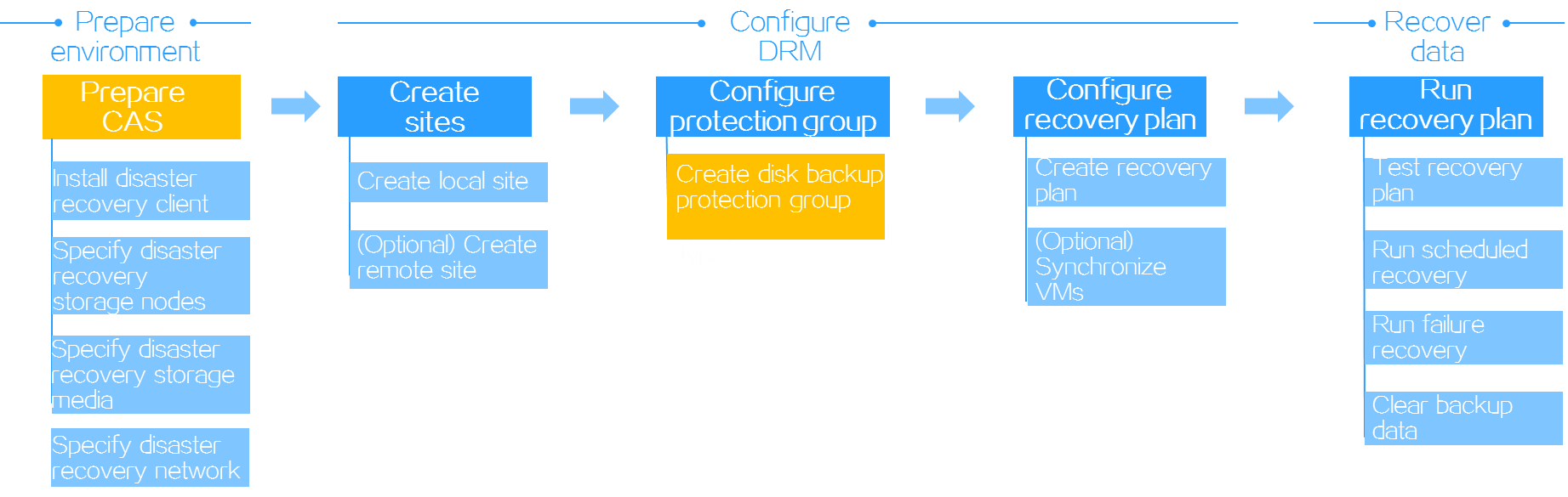
Disaster recovery preparations
Before you configure disk backup-based disaster recovery, perform the following tasks:
1. On the protected site, install the disaster recovery client on protected VMs or bare metal servers.
2. On the recovery site, configure disaster recovery storage nodes, disaster recovery storage media, and disaster recovery network on CAS.
DRM tasks
Configuring sites
On either the protected site or recovery site, configure a local site and a remote site on CAS. For disk backup-based disaster recovery on heterogeneous clouds, you can configure only a local site.
Configuring a protection group
A disk backup protection group protects a set of VMs or bare metal nodes installed with the disaster recovery client by synchronizing data of the protected objects automatically in real time. A disk backup protection group can operate in one of the following modes depending on the services running on its protected objects:
· Common mode—VMs or production nodes operate independently.
· Dual-node mode—Two VMs or production nodes must have shared storage to store the data that can be accessed by both of them.
· Cluster mode—VMs or production nodes must have shared storage to store the data that can be accessed by all of them.
A disk backup protection group supports the following scenarios:
· Homogeneous clouds—CAS CVM systems with the same version run on the protected and recovery sites to protect CVM VMs. In this scenario, you must specify the protected and recovery sites, select VMs installed with the disaster recovery client on the protected site as the protected objects, select a disaster recovery policy, and then configure network mappings between these sites.
· Heterogeneous clouds—CAS CVM protects the VMs on a CVM system with a lower version or VMs or bare metal servers on other platforms, and recovers them on a CAS CVM system with a higher version. In this scenario, you use a local site as the recovery site, specify the VMs or bare metal servers installed with the disaster recovery client as the protected objects, select a disaster recovery policy, and then configure production node network resources on the recovery site.
After you create a protection group, CAS automatically synchronizes VM data. In the homogeneous clouds scenario, you also can manually synchronize VM data before failover.
Configuring a recovery plan
DRM allows you to customize disaster recovery settings by creating recovery plans on a per-protection group basis. When a recovery plan is executed, DRM automatically restores protected objects on the recovery site.
Disaster recovery scenarios
Recovery plan test
DRM allows you to test whether a recovery plan operates correctly by failing over protected objects based on the recovery plan to an isolated test environment on the recovery site without interrupting services. You must manually finish a recovery plan test to clear the environment and restore the state of the recovery plan to Ready.
In disk backup-based disaster recovery, VMs are attached to the volume snapshots on the recovery site.
Figure 13 Recovery plan test for disk backup-based disaster recovery
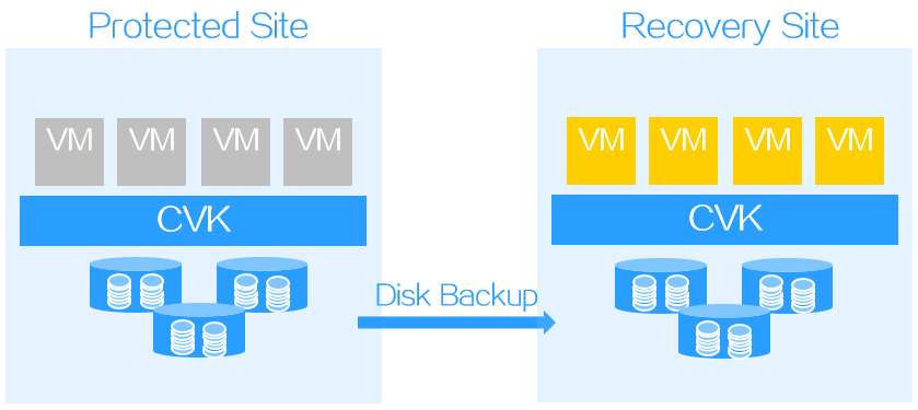
Scheduled recovery
A scheduled recovery resumes protected objects on the recovery site for regular maintenance of the protected site.
In the homogeneous clouds scenario, a scheduled recovery shuts down protected objects and triggers a data replication. DRM resumes VMs on the recovery site only after it finishes copying all protected data to the recovery site.
In a heterogeneous environment, DRM does not shut down protected objects. You must manually shut down them on the protected site.
Figure 14 Scheduled recovery
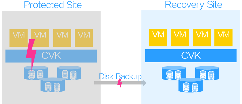
Failure recovery
Failure recovery restores protected objects on the recovery site based on a recover plan to reduce the service interruption time when the protected site fails.
For disk backup-based disaster recovery, the RPO is not 0 when failover recovery is executed.
Figure 15 Failure recovery
Reverse recovery
Disk replication-based disaster recovery can fall back protected objects with the PE reverse recovery tool from a recovery site to a protected site when the protected site recovers from failure. The PE reverse recovery tool runs on the protected site.
Figure 16 Reverse recovery
Backup data clearing
For disk backup-based disaster recovery, you must clear recovered protected objects and temporary data with the PE reverse recovery tool from the recovery site after services fall back to the protected site. The PE reverse recovery tool runs on the protected site.
Configuring storage replication-based disaster recovery
This chapter describes how to configure storage replication-based disaster recovery with storage arrays that support SRAs. For the configuration procedure for storage arrays that do not support SRAs, see "Configuring storage replication-based disaster recovery with storage arrays that do not SRAs."
SRAs enable DRM to discover storage systems, replicate LUNs, and test and perform disaster recovery. When DRM tests disaster recovery, runs scheduled recovery, or runs failure recovery, SRAs offer resources to DRM and cooperate with DRM in disaster recovery automation in a virtualization environment.
Restrictions and guidelines
When you configure storage replication-based disaster recovery, follow these restrictions and guidelines:
· Make sure the protected and recovery sites use the same replication technology.
· Make sure storage replication and snapshot features have been licensed on storage arrays.
· Make sure the data of protected VMs is saved on the shared storage resources that have replication relationships.
· Make sure DRM has been licensed. If you upgrade a version earlier than E0536 to enhanced enterprise edition, you must request a new enhanced enterprise license.
· After you set up the disaster recovery environment, perform data synchronization before you execute recovery plans.
· DRM can automate the whole VM recovery process when cooperating with storage arrays that support SRAs. If storage arrays do not support SRAs, you must manually prepare the storage environment before failing over services.
· Before you upgrade CAS from a version earlier than E0708 to E0708 or later, delete all protection groups and recovery plans. After the upgrade, re-create protection groups and reconfigure DRM.
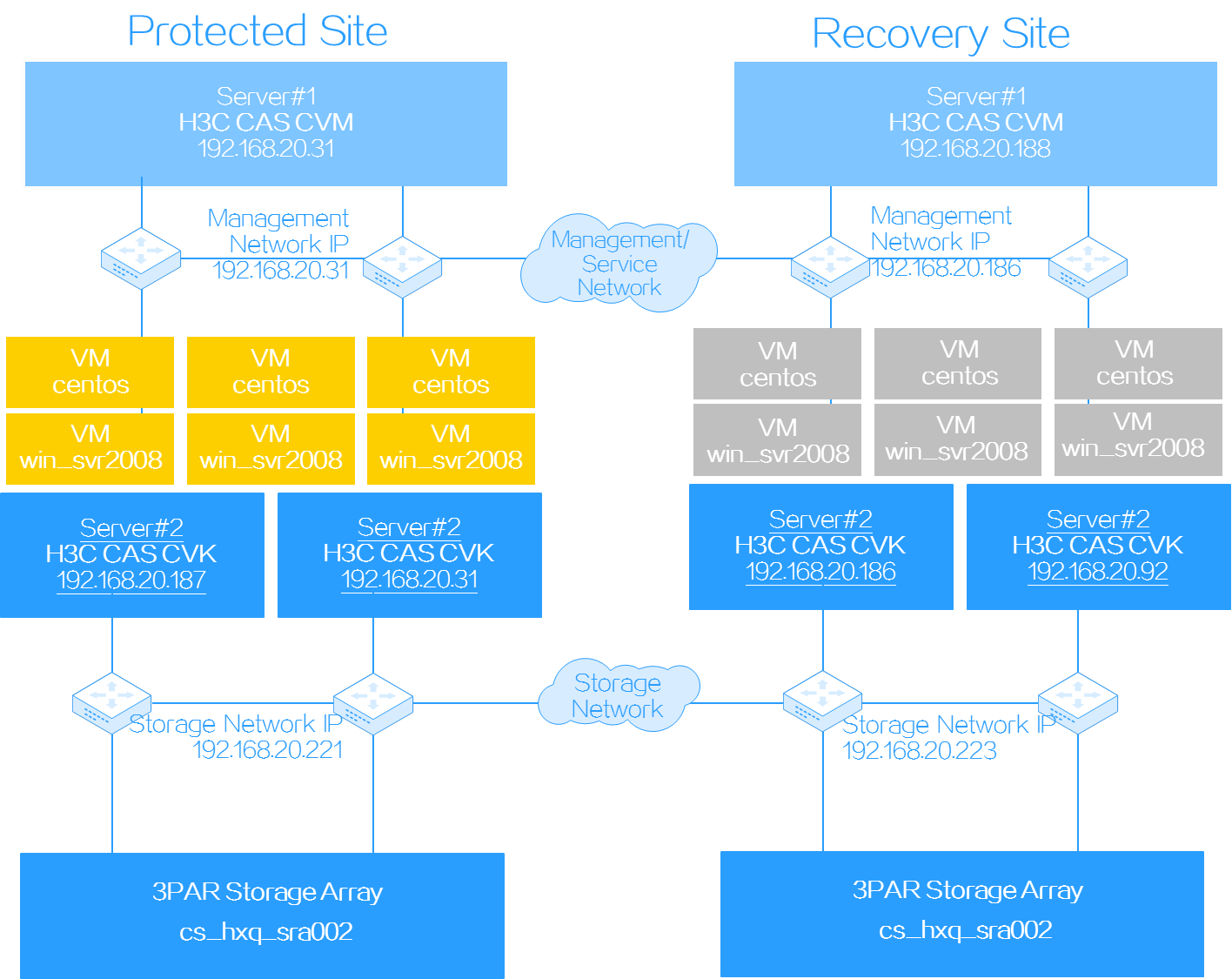
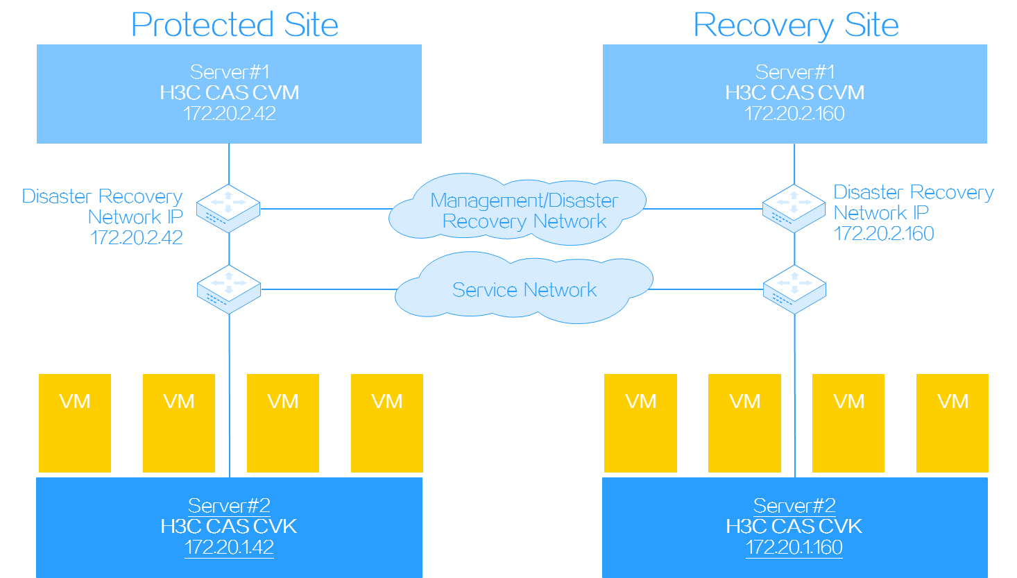
Network diagram
Figure 17 Network diagram
Configuring storage arrays and DRM
Preparing the storage environment
Restrictions and guidelines
To add new replication relationships for CVM after replication relationships have been synchronized, follow this procedure:
1. Configure replication settings on storage servers.
2. Verify that all recovery plans are in initialized state and synchronize replication relationships again.
When CAS cooperates with 3PAR storage, follow these restrictions and guidelines:
· When you create remote copy groups, make sure the LUNs that are related in a remote copy group use the same WWN.
· When you add a LUN as a shared file system or block device on CVK, make sure the LUN does not belong to any remote copy group or is a member of a primary remote copy group.
· DRM supports disaster recovery in the event of primary CVM failure or failure of the link to the primary storage server. DRM does not support disaster recovery if the primary storage server fails.
· Before you synchronize replication relationships on CAS, make sure the remote copy groups used by CAS do not have the Primary-Rev or Secondary-Rev role.
· Do not switch over, restore, start, or stop the remote copy groups that are members of protection groups on storage servers. These operations change the roles and status of the remote copy groups and cause a DRM recovery or recovery plan test to fail.
· When you create remote copy groups, use RCFC instead of RCIP. CAS does not support data replication over RCIP when cooperating with 3PAR storage.
Procedure
1. Set up a synchronous or asynchronous replication environment and configure peer persistence on 3PAR storage as descried in 3PAR storage server installation guides and peer persistence configuration guide.
2. Log in to HP 3PAR Management Console with the management IP addresses, usernames, and passwords of two 3PAR storage servers.
Figure 18 Logging in to HP 3PAR Management Console
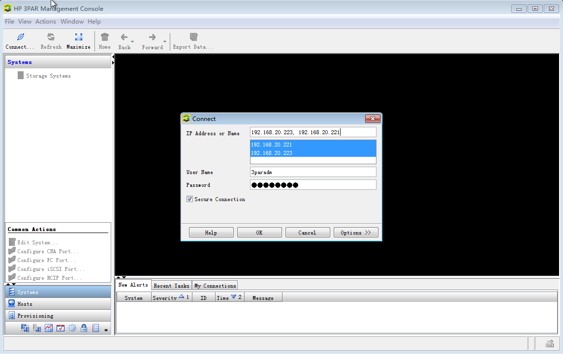
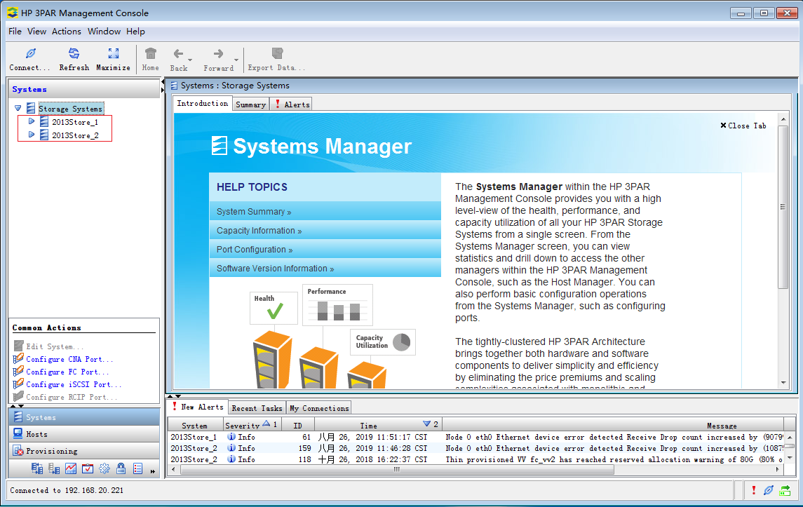
Figure 19 shows storage servers 2013Store_1 and 2013Store_2, which will be used for active-active replication. Primary storage server 2013Store_1 will be attached to hosts on the primary CVM system on the protected site, and secondary storage server 2013Store_2 will be attached to hosts on the backup CVM system on the recovery site.
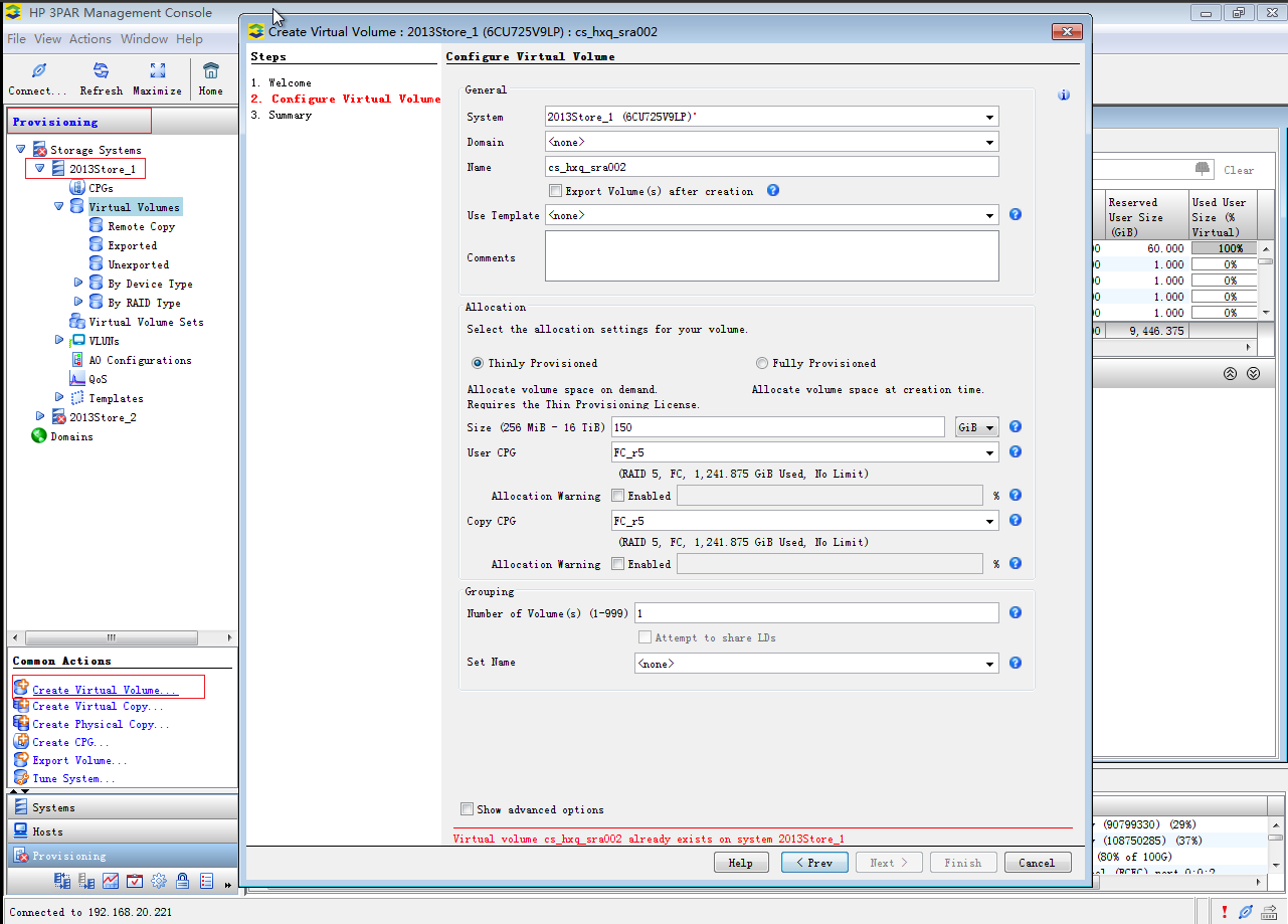
3. From the left navigation tree, select Provisioning > 2013Store_1, and then click Create Virtual Volume in the Common Actions section to create a virtual volume named cs_hxq_sra002.
Figure 20 Creating a virtual volume on storage server 2013Store_1
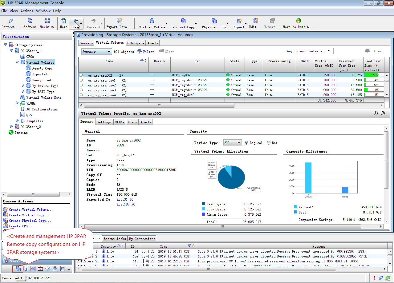
4. Click <Create and management HP 3PAR Remote copy configurations on HP 3PAR storage systems> in the bottom left.
Figure 21 Accessing the remote copy manager
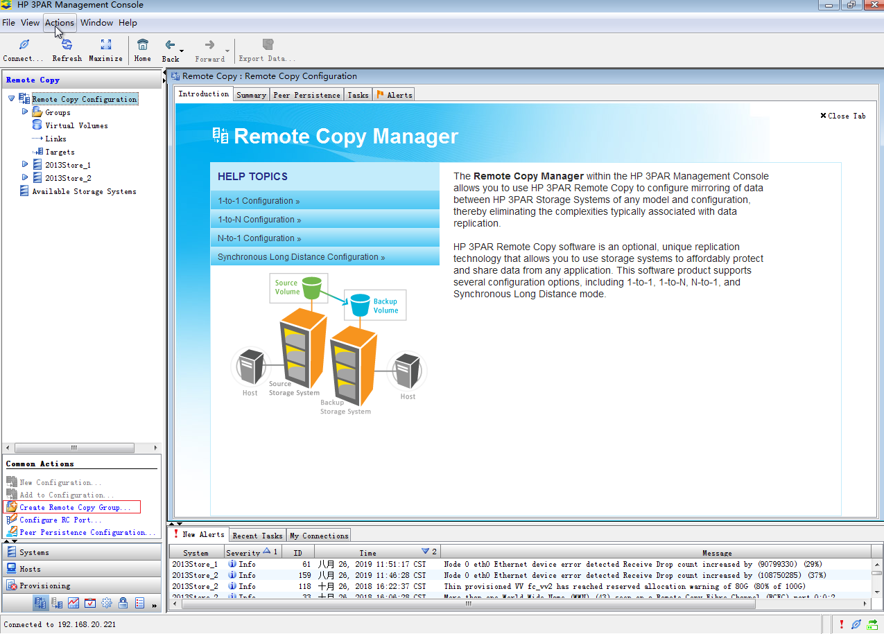
5. Click Create Remote Copy Group in the Common Actions section.
Figure 22 Creating a remote copy group
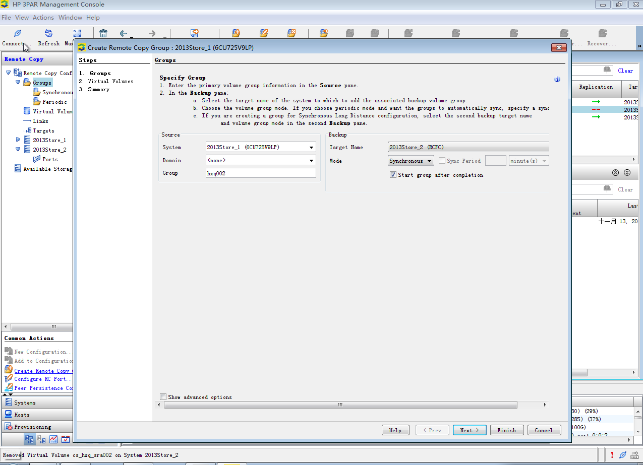
6. Select the primary storage server for the System parameter, enter hxq002 as the remote copy group name, and then click Next >.
Figure 23 Configuring the remote copy group
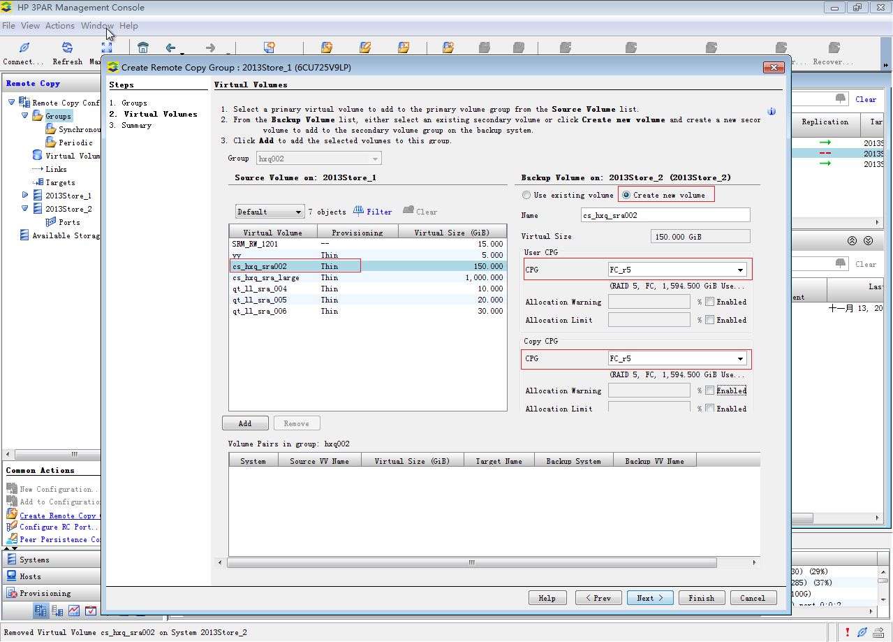
7. Select cs_hxq_sra002 from the source volume list, select Create new volume for the backup volume, and them select the same CPG for the User CPG and Copy CPG parameters.
|
|
CAUTION: Select Create new volume to ensure that the volumes on the primary and secondary storage servers use the same WWN. If you select Use existing volume, WWN inconsistency might cause communication issues. |
Figure 24 Specifying source and backup volumes
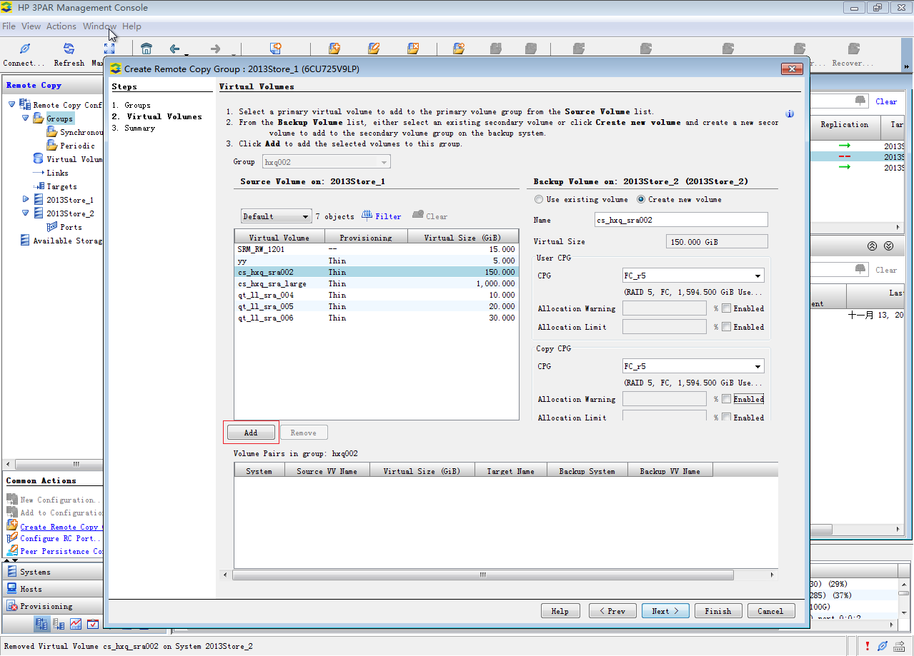
8. Click Add and follow the steps to add the source and backup volumes to the remote copy group.
Figure 25 Adding the source and backup volumes to the remote copy group
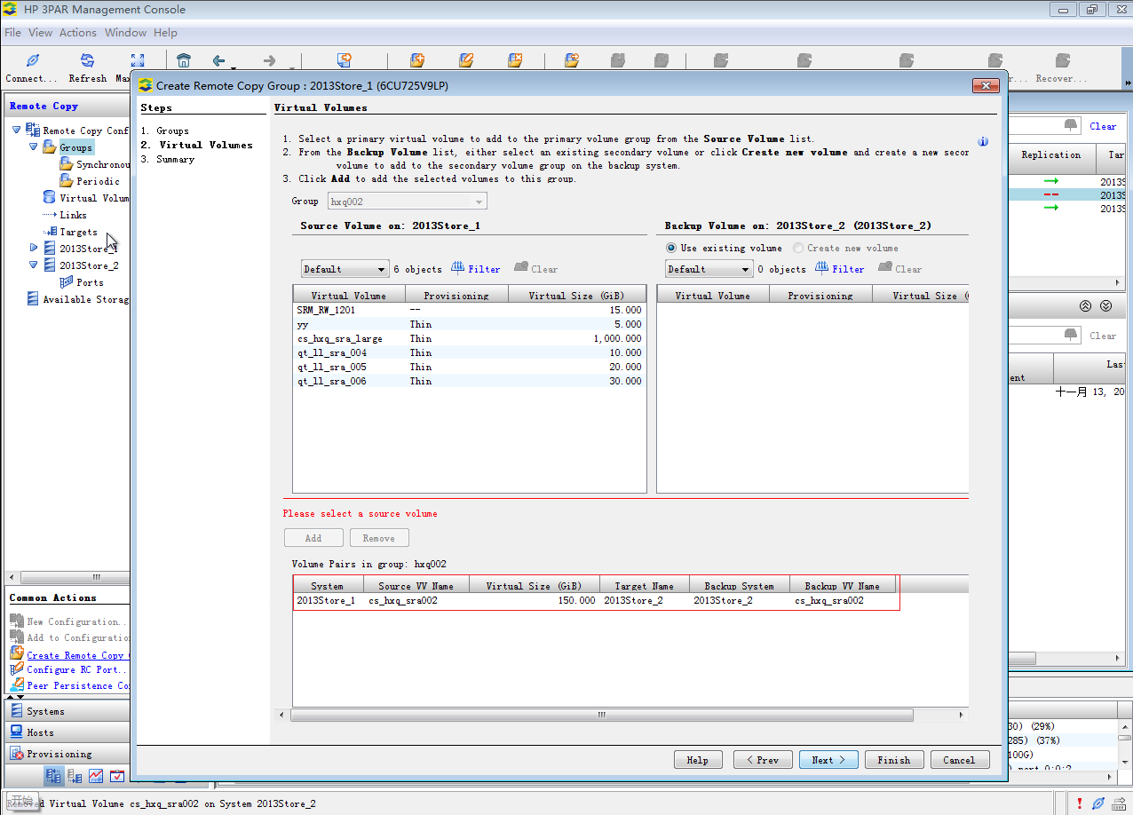
9. Check the added volume pair.
Figure 26 Checking the added volume pair
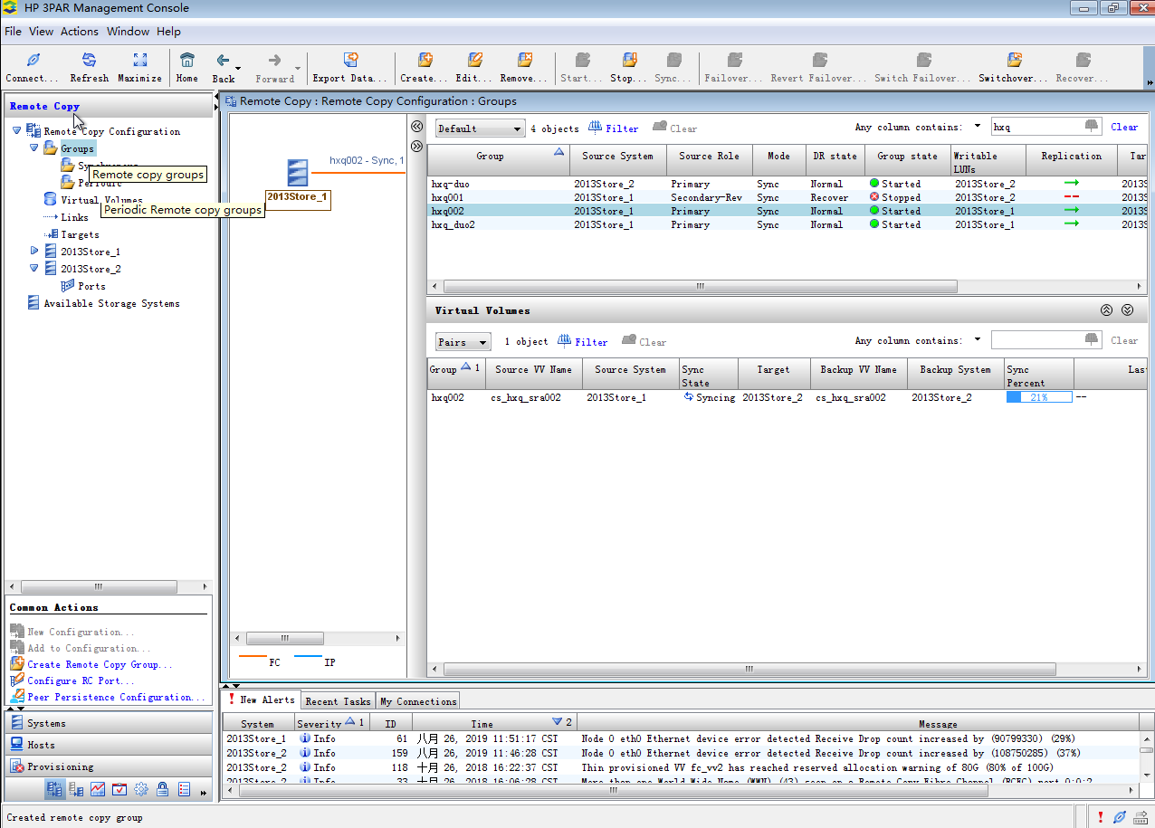
10. From the left navigation tree, select Remote Copy Configuration > Groups to view the role and volumes of the remote copy group.
Figure 27 Checking the role and volumes of the remote copy group
11. Check the backup volume created on secondary storage server 2013Store_2.
Figure 28 Checking the backup volume
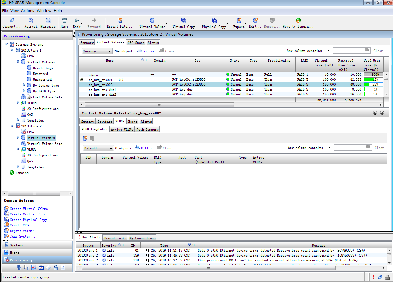
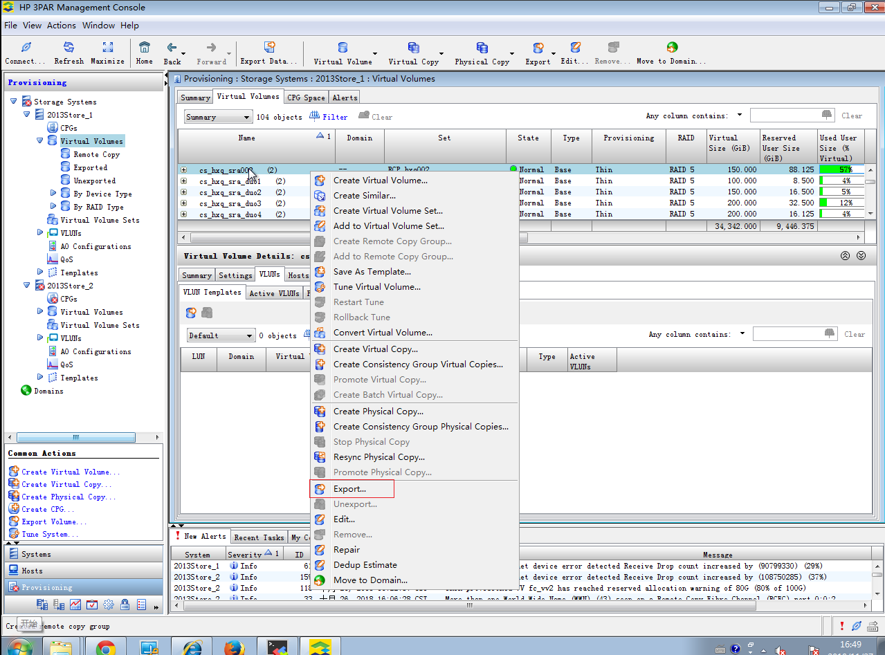
12. On storage server 2013Store_1, right-click virtual volume cs_hxq_sra002 and select Export to map it to the hosts on the protected site. On storage server 2013Store_2, right-click virtual volume cs_hxq_sra002 and select Export to map it to the hosts on the recovery site.
Figure 29 Mapping the virtual volumes to hosts
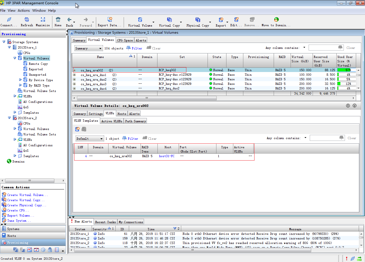
13. On storage server 2013Store_1, verify that virtual volume cs_hxq_sra002 has been mapped to host host31.
Figure 30 Checking the host mapping on the primary storage server
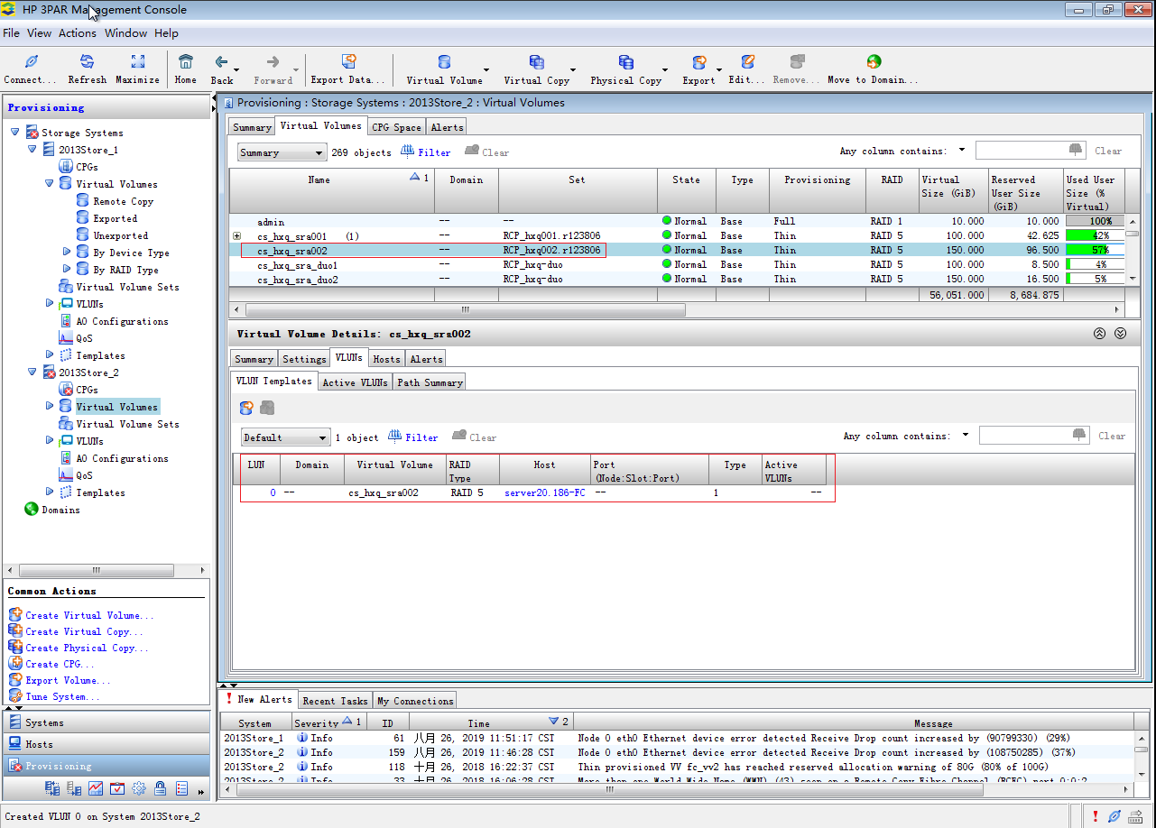
14. On storage server 2013Store_2, verify that virtual volume cs_hxq_sra002 has been mapped to host host20.
Figure 31 Checking the host mapping on the secondary storage server
Configuring CAS
Add the storage volumes configured in "Preparing the storage environment" as shared file systems or block devices on CAS. You only need to add the storage volume on the primary storage server as an FC shared file system to the primary CVM system. CAS will add a shared file system on the backup CVM system automatically after you create a protection group.
Restrictions and guidelines
A shared file system can contain only one storage volume (corresponds to a LUN).
After you attach storage resources to VMs on CAS, synchronize the storage resources at least twice before you perform data recovery. This avoids data loss in a recovery plan test.
3PAR SRM supports FC shared file systems and FC network storage.
Procedure
1. Log in to CAS CVM.
2. From the left navigation pane, select Resources > Host Pool Name.
3. Click the Shared File Systems tab.
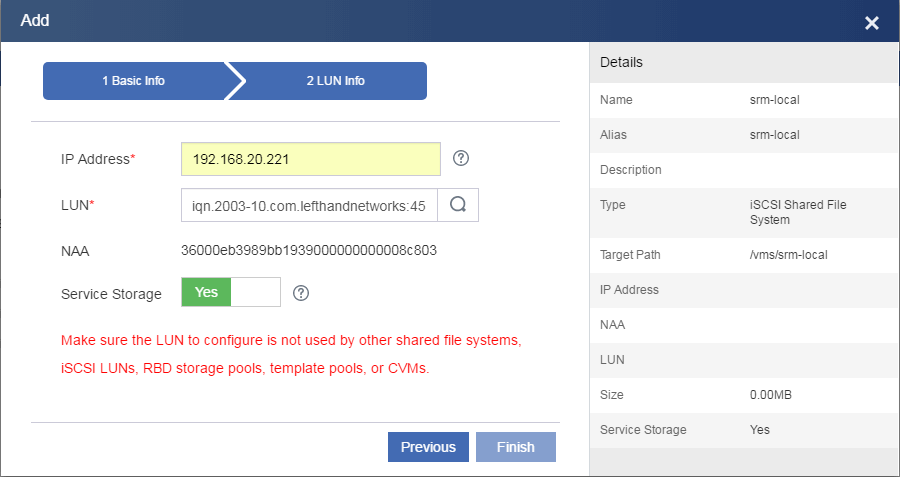
4. Click Add.
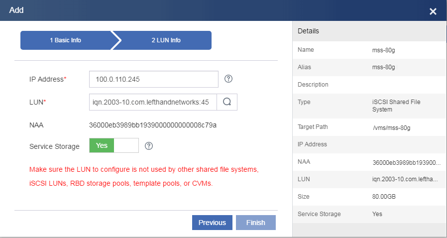
5. Add the LUN on the primary storage server as a shared file system.
If you add the LUN as network storage, attached it to a host directly.
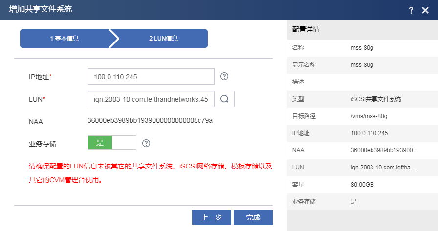
Figure 32 Configuring basic parameters for the shared file system

Figure 33 Configuring LUN settings for the shared file system
6. From the left navigation pane, select Resources > Host Pool Name > Cluster Name.
7. Click the Storage tab.
8. Click Add.
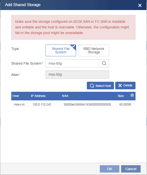
9. Attach the shared file system to hosts.
Figure 34 Attaching the shared file system to hosts

10. From the left navigation pane, select Cloud Resources > Host Pool Name > Cluster Name > Host Name.
11. Click Add VM.
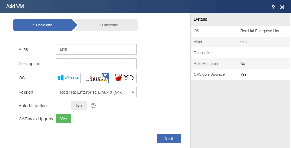
12. Create a VM and attach the shared file system as a storage pool to the VM.
Figure 35 Configuring basic parameters for the VM
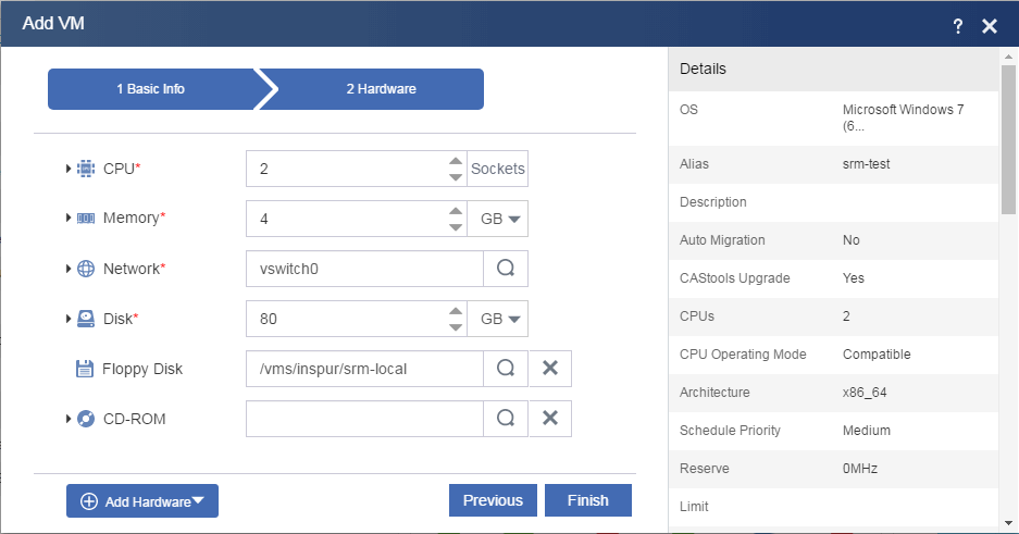
Figure 36 Attaching the shared file system to the VM
Configuring DRM
Configuring sites
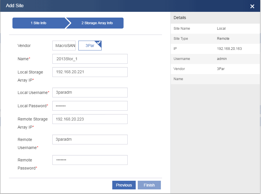
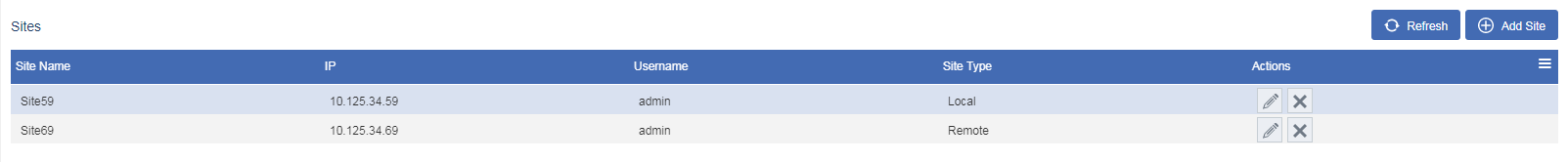
You can add sites on either the primary or backup CVM system.
To configure sites:
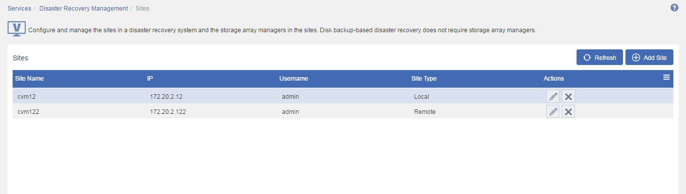
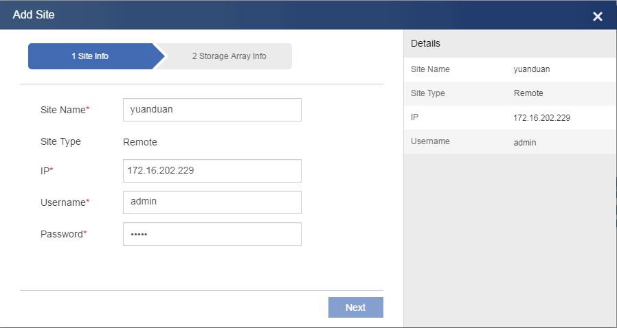
1. From the left navigation pane, select Services > Disaster Recovery Management > Sites.
2. Click Add Site.
3. Configure a local site.
Enter the IP address of the local CVM system. By default, a site added first is a local site (protected site). The sites added subsequently are all remote sites.
4. Configure a storage array manager, and then click Finish.
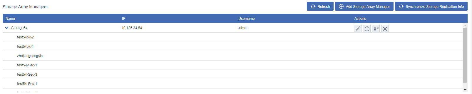
Figure 37 Configuring a storage array manager
5. Click the ![]() icon for the storage array manager to verify connectivity to the
storage resources managed by it.
icon for the storage array manager to verify connectivity to the
storage resources managed by it.
Figure 38 Testing connectivity
6. Add a remote site in the same way the local site is added.
Figure 39 Adding a remote site
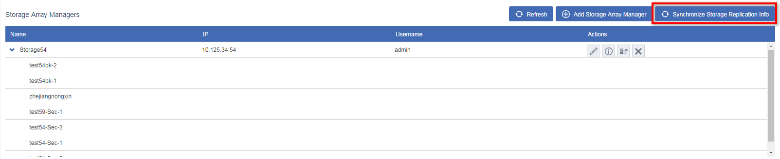
7. Click Synchronize Storage Replication.
Figure 40 Synchronizing replication relationships
8. Click the ![]() icon
for the storage array manager to verify replication relationships.
icon
for the storage array manager to verify replication relationships.
Figure 41 Verifying replication relationships

Configuring a protection group
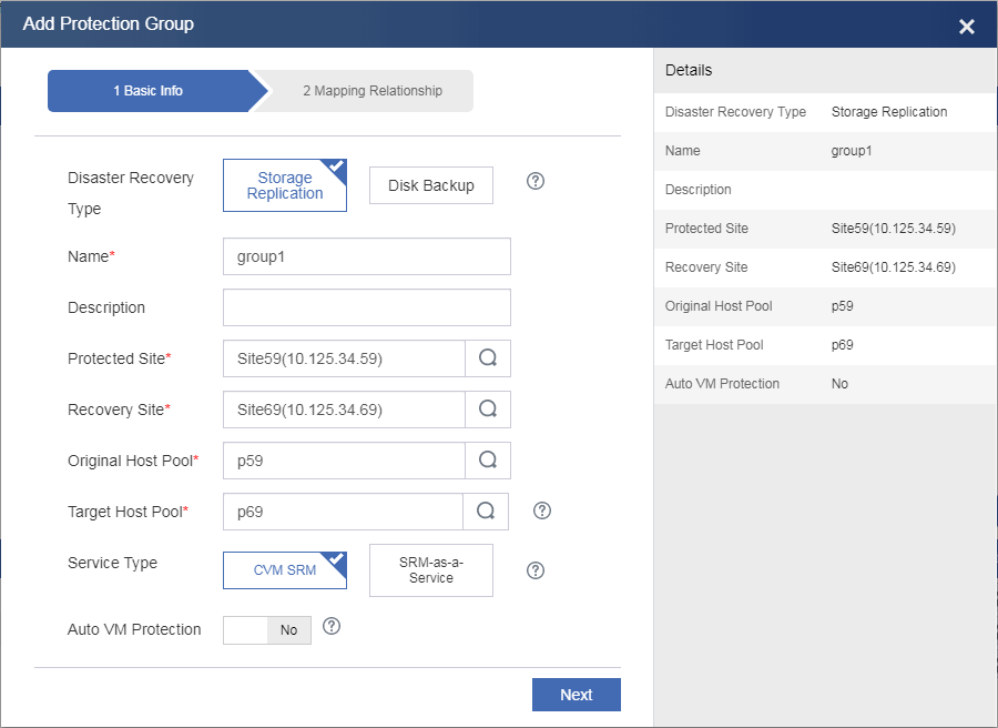
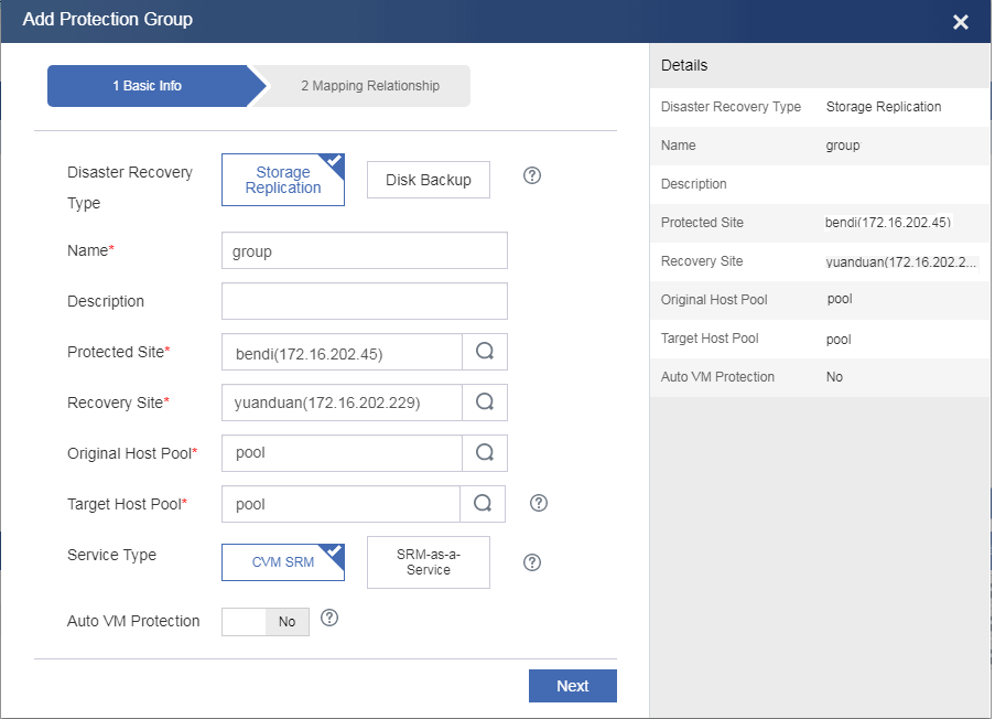
1. From the left navigation pane, select Services > Disaster Recovery Management > Protection Groups.
2. Click Add Protection Group.
3. Select Storage Replication as the disaster recovery type, select the protected and recovery sites, select host pools for the sites, and then click Next.
If you enable auto VM protection, a VM is automatically added to a protection group if it meets the following requirements:
¡ The storage pool, vSwitch, and port profile used by the VM belong to the protection group.
¡ No VM with the same name exists in the protection group.
¡ The VM does not use any local devices of a host, such as a floppy drive.
CAS does not protect the backup files and snapshots of the VMs in a protection group. When the VMs are recovered on the recovery site, their backup files and snapshots are deleted.
Figure 42 Configuring a protection group
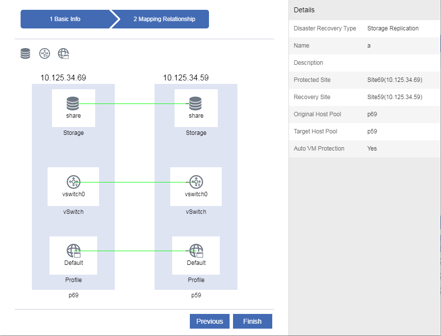
4. To add a resource
mapping, drag the ![]() ,
, ![]() , or
, or ![]() icon.
icon.
When you add a storage mapping, select the storage resources configured in "Configuring CAS."
You can use management network or service network vSwitches and select port profiles as needed. You can create mappings between shared file systems or block devices.
Figure 43 Selecting storage
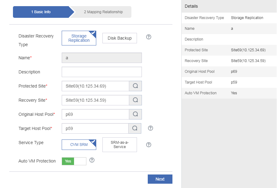
Figure 44 Selecting a device

5. Click Finish.
Figure 45 Resource mappings
6. Click Add VM for the protection group.
7. Select VMs and then click OK.
If you enable auto VM protection, the system displays the VMs that meet the requirements for joining the protection group.
Creating a recovery plan
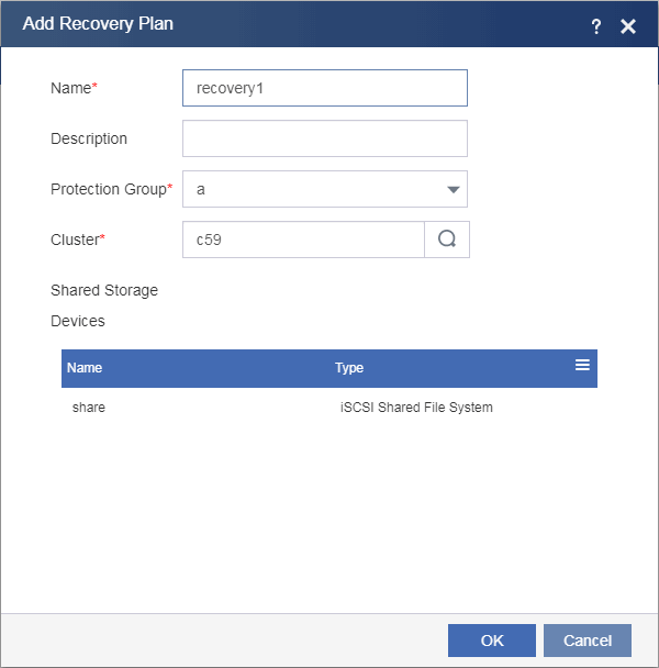
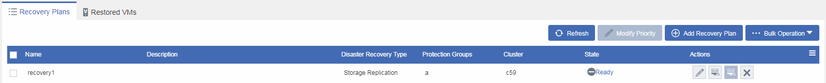
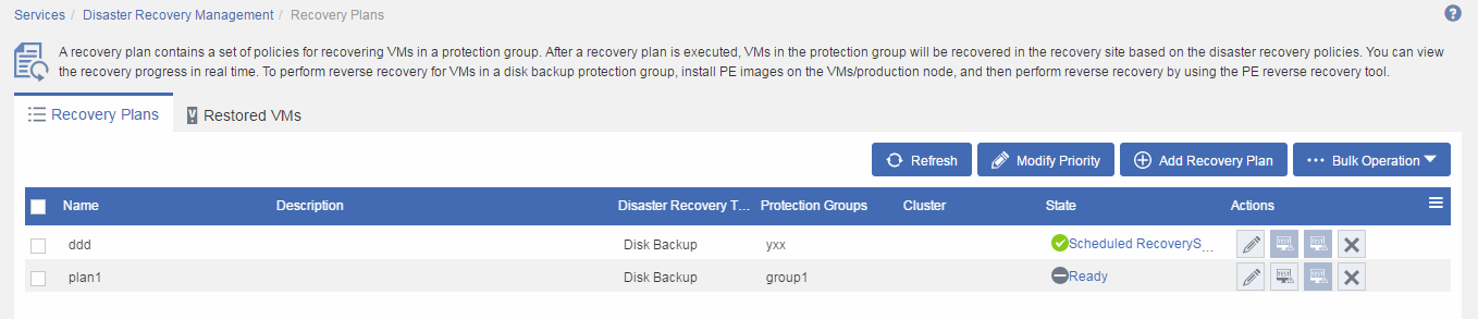
1. From the left navigation pane, select Services > Disaster Recovery Management > Recovery Plans.
2. Click Add Recovery Plan.
3. Enter a name and a description, select the protection group you have added, select a cluster for accommodating recovered VMs, and then click OK.
A protection group can be specified in one recovery plan.
Figure 46 Configuring the recovery plan
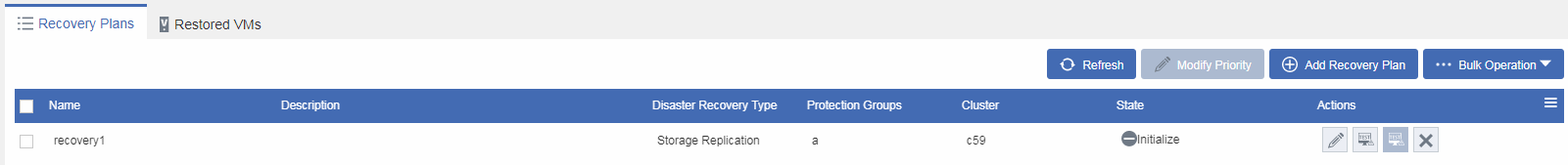
The recovery plan is in Initialize state after creation.
Figure 47 Recovery plan
Running a recovery plan
UIS Manager provides the following options to run a recovery plan:
· Testing a recovery plan.
· Running scheduled recovery.
· Running failure recovery.
· Running reverse recovery.
Restrictions and guidelines
· You can run a recovery plan by following the recovery steps or directly restoring VMs if all steps in the recovery plan are ready before VM restoration.
· Make sure protected VMs can reach the storage resources specified in storage mappings during execution of a recovery plan, and the recovery cluster has enough resources to restore the protected VMs.
· During execution of a recovery plan, make sure the following requirements are met:
¡ The protected and recovery sites are operating correctly and have connectivity.
¡ Hosts with mapped storage resources attached are operating correctly.
Testing a recovery plan
A recovery plan test simulates the process of recovering services on the recovery site upon protected site failure to verify the correctness of a recovery plan. The test does not affect the services provided by the protected site and is manually started and stopped.
In a recovery plan test, protected VMs are attached to the LUNs of the recovery site. You must manually finish a recovery plan test to clear disaster recovery data and restore the state of the recovery plan to Ready.
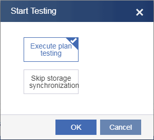
Starting testing a recovery plan
1. From the left navigation pane, select Services > Disaster Recovery Management > Recovery Plans > Recovery Plan Name.
2. Click Start Testing.
3. In the dialog box that opens, select an execution mode, and then click OK.
To isolate the test environment from the production environment, you must edit the vSwitch and port profile mapping settings of the recovery site for the protection group protected by the recovery plan.
Figure 48 Selecting an execution mode
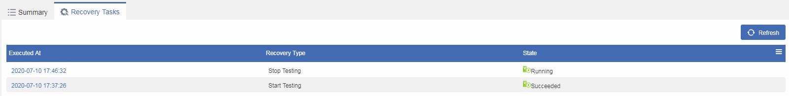
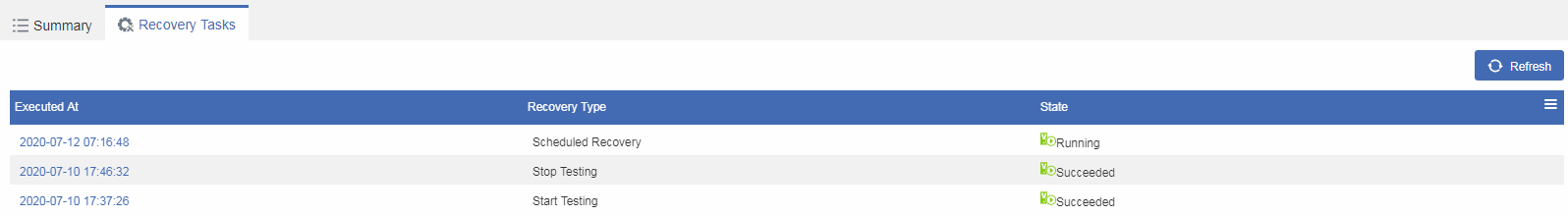
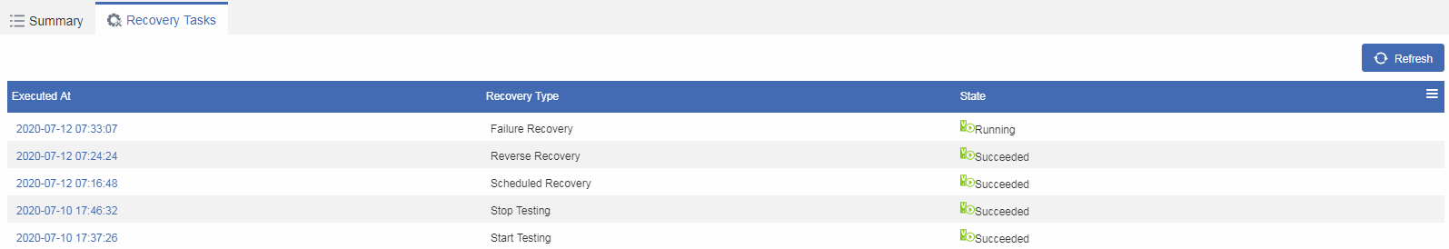
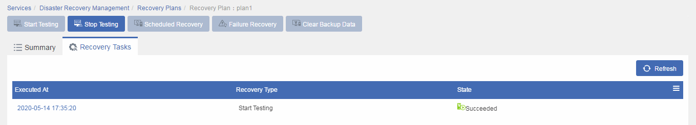
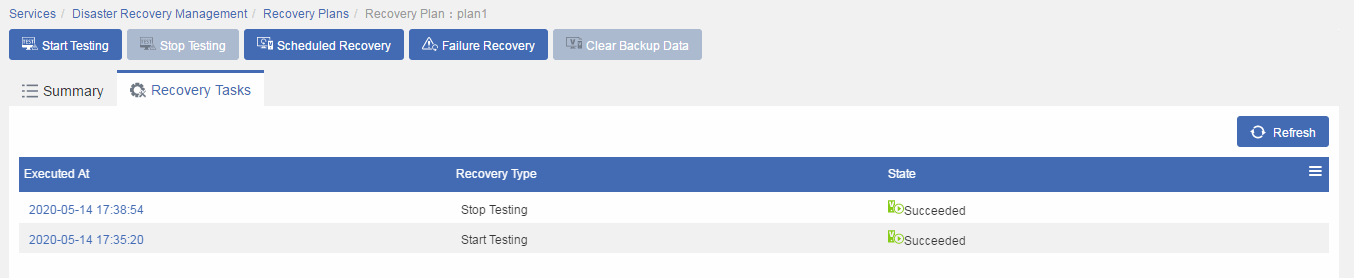
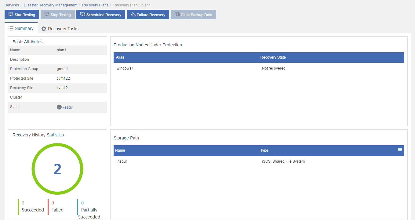
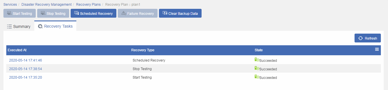
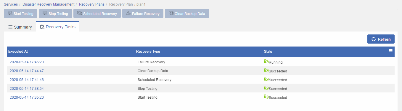
4. Click the Recovery Tasks tab to view the state of the recovery task.
Figure 49 Recovery task state
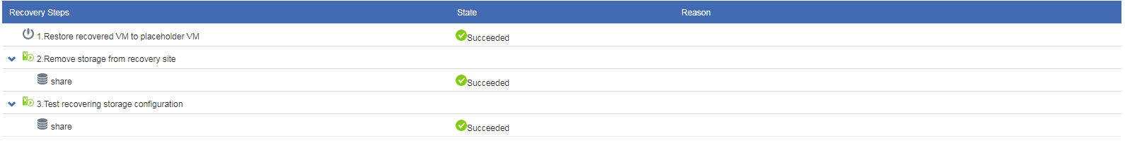
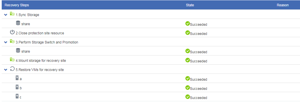
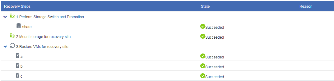
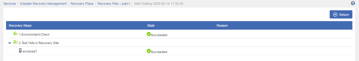
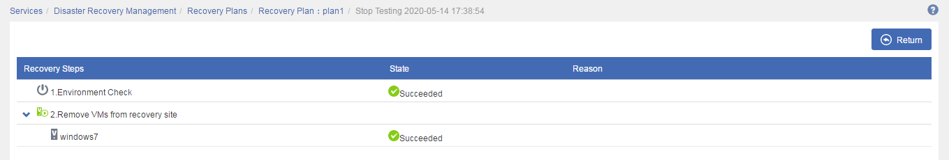
5. Click the execution time link for the recovery task to view test details.
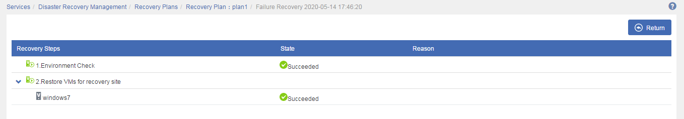
Figure 50 Viewing test details

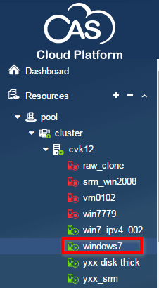
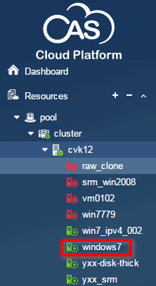
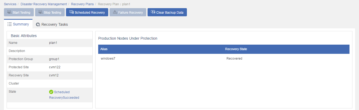
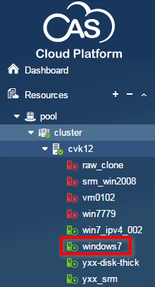
6. Verify that the protected VMs have been restored on the hosts with mapped storage resources attached on the recovery site.
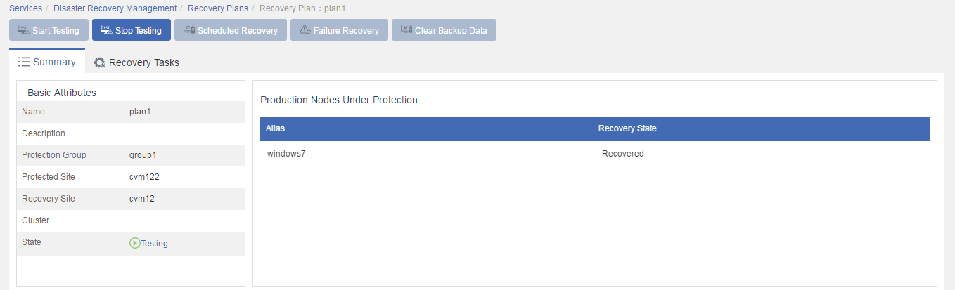
Finishing testing a recovery plan
1. Click Stop Testing on the recovery plan summary page.
2. Click the Recovery Tasks tab to view the state of the recovery task.
Figure 51 Recovery task state

3. Click the execution time link for the recovery task to view test details.
Figure 52 Viewing test details
4. Verify that the protected VMs have been deleted from the recovery site, and the mapped storage resources have been removed.
5. Verify that the recovery plan is in Ready state.
To avoid communication issues, you must change the network settings in the mapped port profiles and vSwitches to the state before the test.
Figure 53 Recovery plan in Ready state
Running scheduled recovery
Scheduled recovery shuts down the protected VMs on the protected site and replicates their data to the recovery site for maintenance purposes when both sites are operating correctly.
To run scheduled recovery:
1. From the left navigation pane, select Services > Disaster Recovery Management > Recovery Plans > Recovery Plan Name.
2. Click Scheduled Recovery.
3. In the dialog box that opens, select an execution mode, and then click OK.
4. Click the Recovery Tasks tab to view the state of the recovery task.
Figure 54 Recovery task state
5. Click the execution time link for the recovery task to view task details.
Figure 55 Viewing task details
Running reverse recovery
Reverse recovery restores the protected VMs from the recovery site to the protected site when the protected site recovers or after scheduled recovery is performed.
To run reverse recovery:
1. From the left navigation pane, select Services > Disaster Recovery Management > Recovery Plans > Recovery Plan Name.
2. Click Reverse Recovery.
3. In the dialog box that opens, select an execution mode, and then click OK.
4. Click the Recovery Tasks tab to view the state of the recovery task.
Figure 56 Recovery task state
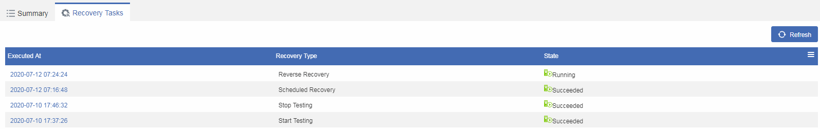
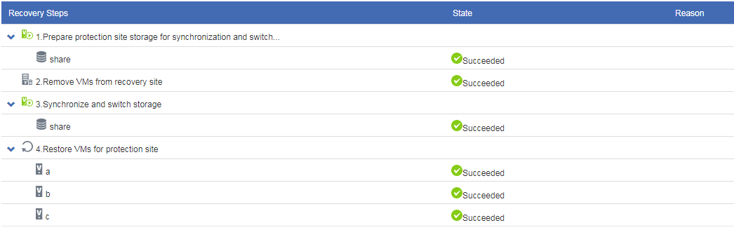
5. Click the execution time link for the recovery task to view task details.
Figure 57 Viewing task details
Running failure recovery
You can run a recovery plan by following the recovery steps or directly restoring VMs if all steps in the recovery plan are ready before VM restoration.
To run failure recovery:
1. From the left navigation pane, select Services > Disaster Recovery Management > Recovery Plans > Recovery Plan Name.
2. Click Failure Recovery.
3. In the dialog box that opens, select an execution mode, and then click OK.
4. Click the Recovery Tasks tab to view the state of the recovery task.
Figure 58 Recovery task state
5. Click the execution time link for the recovery task to view task details.
Figure 59 Viewing task details
Configuring disk backup-based disaster recovery
This chapter describes how to configure disk backup-based disaster recovery to protect VMs when the protected and recovery sites are deployed with the same CAS CVM version.
Network diagram
Figure 60 Network diagram
Restrictions and guidelines
For CAS to identify CentOS VMs correctly and perform disk backup-based disaster recovery, configure correct network settings for CentOS VMs.
Preparing the protected site
Downloading a disaster recovery client
Restrictions and guidelines
After you register the migration license, you can configure a secondary IP address for the backup server in case the primary IP address is unavailable. By default, the secondary IP address of the backup server is the management network IP address of CVM.
For homogeneous clouds, download a client from the backup CVM system for protected VMs to automatically connect to the backup server.
Procedure
1. Log in to the backup CVM system on the recovery site.
2. From the left navigation pane, select Services > Disaster Recovery Management > Download Client.
3. Download a proper client for protected VMs by using one of the following methods:
¡ Click a client name to download a ZIP package whose name is prefixed with Clone_Client, Clone_Client_Redhat5x86_64.zip for example. Then, decompress the package and transfer the client to protected VMs through an FTP tool.
¡ Click
the ![]() icon for a client
to generate a URL and copy the URL to VMs through remote consoles. Then
download the client to the VMs from the URL.
icon for a client
to generate a URL and copy the URL to VMs through remote consoles. Then
download the client to the VMs from the URL.
Figure 61 Downloading the disaster recovery client

Installing the disaster recovery client on VMs
Restrictions and guidelines
As a best practice, disable firewalls and security policies on protected VMs before you install the disaster recovery client. If the VMs are CAS VMs, make sure security group policies open the migration tool port on the VMs.
Procedure
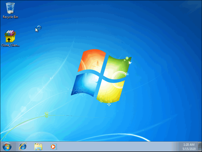
1. Log in to a VM from a console.
Figure 62 Logging in to a VM
2. Double click Clone_Client_Win.exe, select a language, and then click OK.
3. Accept the license agreement, select an installation path, and start installing the client.
4. Permit CDP driver installation.
5. Select whether to restart the VM.
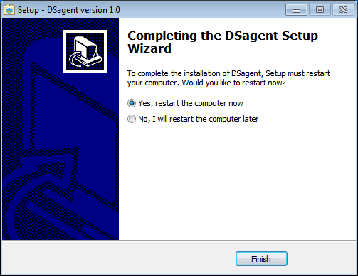
Restarting a Windows VM interrupts services. Please plan the restart schedule to reduce the impact on services.
Figure 63 Restarting the VM
Preparing the recovery site
Specifying disaster recovery storage nodes
A disaster recovery storage node distributes and processes data during service protection and data transmission and can provide more storage space and capabilities. Only a host that operates as a disaster recovery storage node can be used as the destination host for a VM to restore.
To specify a disaster recovery storage node:
1. Log in to the backup CVM system.
2. From the left navigation pane, select Resources > Host Pool Name > Host Name.
3. Click More, and then select Set as Storage Node.
Figure 64 Specifying a disaster recovery storage node
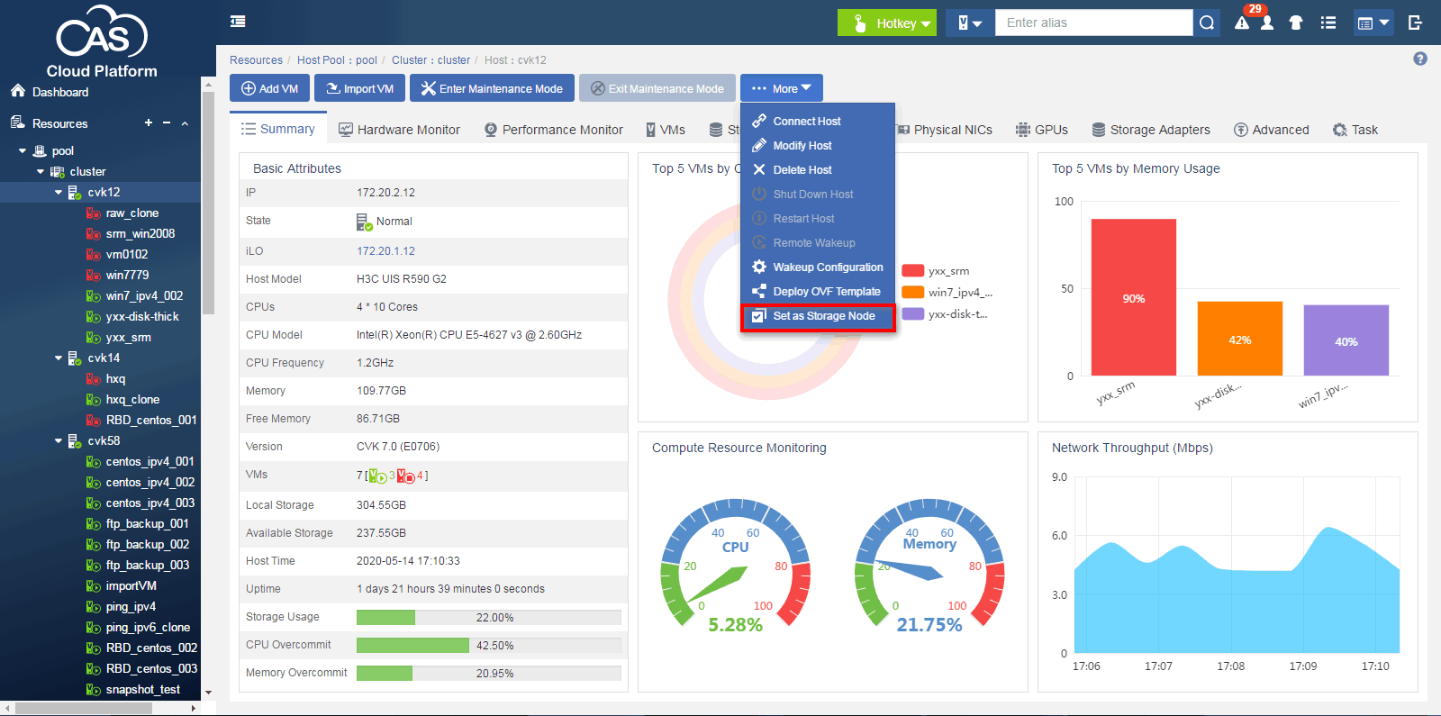
4. In the dialog box that opens, click OK.
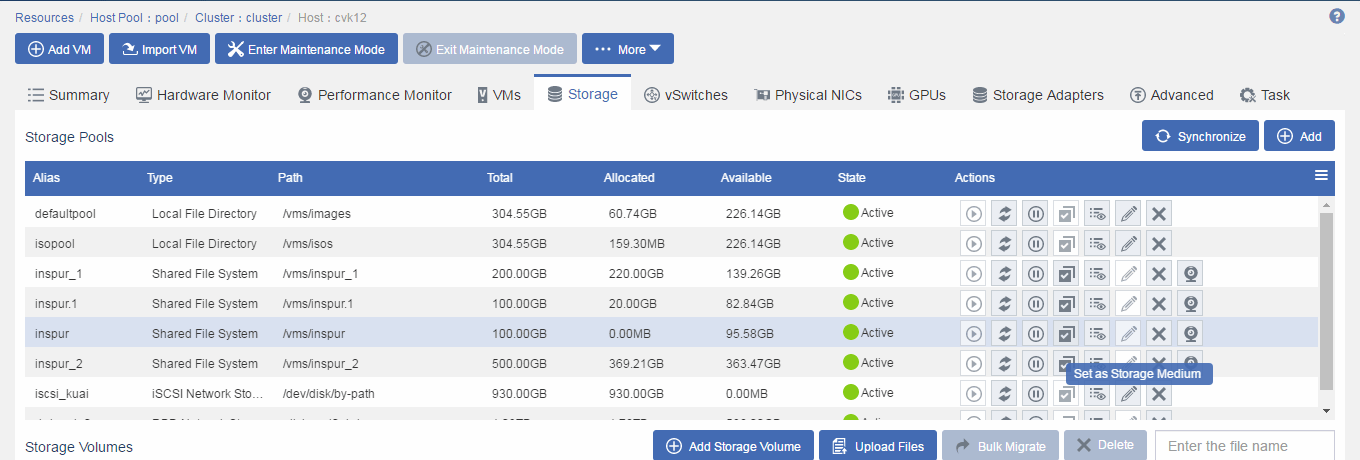
Configuring a storage pool as a storage medium on a disaster recovery storage node
A storage medium stores disaster recovery backup data. A storage pool can be used as the destination storage pool for disk backup-based disaster recovery only after it is configured as a storage medium. A storage node will go offline and then come online after you configure its storage pool as a storage medium.
To configure a storage pool as a storage medium on a disaster recovery storage node:
1. From the left navigation pane, select Resources > Host Pool Name > Host Name.
2. Click the Storage tab.
3. Click the ![]() icon for the storage pool, and then click OK in
the dialog box that opens.
icon for the storage pool, and then click OK in
the dialog box that opens.
Figure 65 Configuring a storage pool as a storage medium
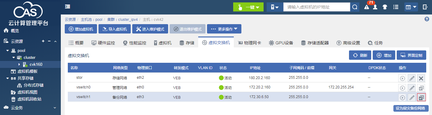
Changing the network type of a vSwitch from backup to disaster recovery
A disaster recovery network transmits backup data for disaster recovery. You can change the network type of a vSwitch from backup to disaster recovery when its network type is backup network. If you do not specify a disaster recovery network vSwitch, backup data is transmitted through management network vSwitch vswitch0.
To change the network type of a vSwitch from backup to disaster recovery:
1. From the left navigation pane, select Resources > Host Pool Name > Host Name.
2. Click the vSwitches tab.
3. Click the ![]() icon for a vSwitch,
and then click OK in the dialog box that opens.
icon for a vSwitch,
and then click OK in the dialog box that opens.
Figure 66 Changing the network type of a vSwitch from backup to disaster recovery
Configuring DRM
Configuring sites
1. From the left navigation pane, select Services > Disaster Recovery Management > Sites.
2. Click Add Site.
3. Configure a local site.
Enter the IP address of the local CVM system. By default, a site added first is a local site (protected site). The sites added subsequently are all remote sites.
You do not need to configure storage array settings for disk backup-based disaster recovery.
4. Configure the remote site.
Figure 67 Configuring sites
Configuring a protection group
1. From the left navigation pane, select Services > Disaster Recovery Management > Protection Groups.
2. Click Add Protection Group.
3. Select Disk Backup as the disaster recovery type, and configure basic parameters.
For homogeneous clouds, you must select the protected and recovery sites.
For heterogeneous clouds, you do not need to select the protected site.
Figure 68 Configuring basic parameters for a protection group
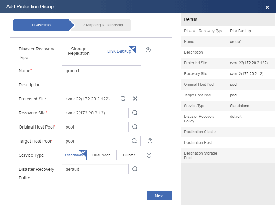
4. Select an existing disaster recovery policy or create a new one.
A disaster recovery policy contains synchronization and snapshot settings. For more information about disaster recovery policy configuration, see the online help for CAS.
|
|
IMPORTANT: To ensure data consistency between the protected and recovery sites, set a proper synchronization interval based on your services. A value of 0 indicates that synchronization is disabled. |
5. Click Next.
6. To add a resource
mapping, drag the ![]() , or
, or ![]() icon.
icon.
For heterogeneous clouds, configure network mappings by specifying disaster recovery network vSwitches and port profiles.
Figure 69 Configuring resource mappings
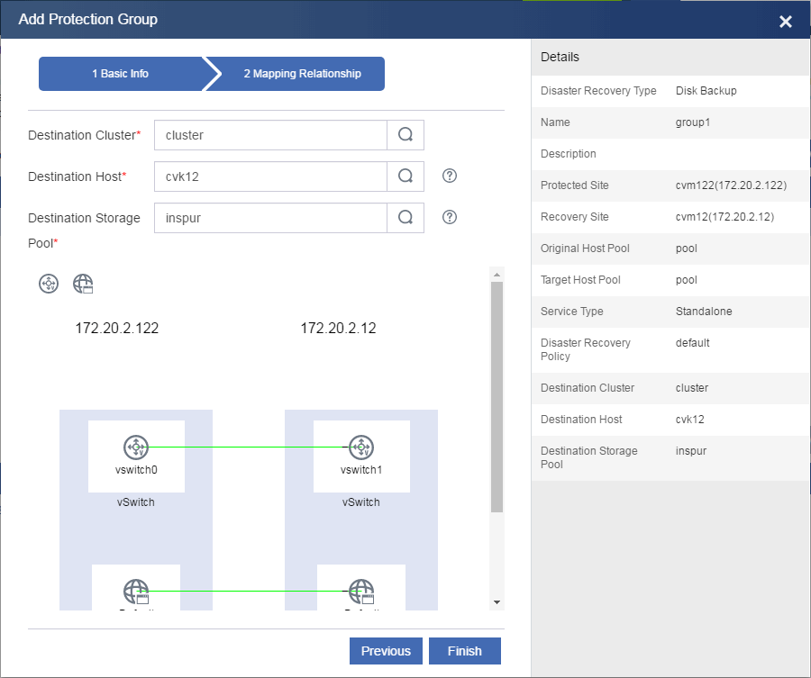
7. Click Finish.
8. Click Add VM for the protection group.
9. Select VMs and then click OK.
The system displays the VMs that have the disaster recovery client installed and have correct network settings.
Figure 70 Selecting VMs
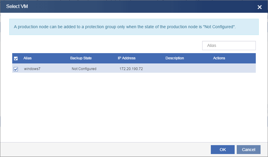
Figure 71 Protected VMs
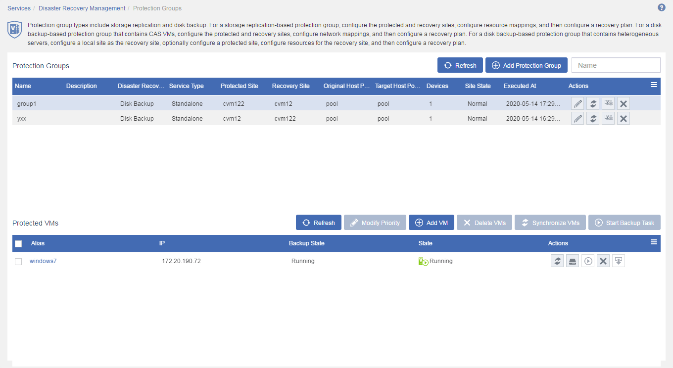
Creating a recovery plan
1. From the left navigation pane, select Services > Disaster Recovery Management > Recovery Plans.
2. Click Add Recovery Plan.
3. Enter a name and a description, select the protection group you have added, select protected VMs, and then click OK.
You can configure multiple recovery plans to meet different requirements of VMs in a protection group. In this example, all VMs use the same recovery plan.
Figure 72 Configuring a recovery plan
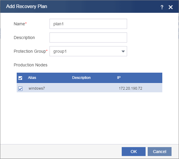
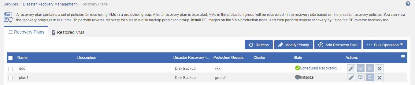
The recovery plan is in Initialize state after creation.
Figure 73 Recovery plan
Running a recovery plan
Testing a recovery plan
Starting testing a recovery plan
1. From the left navigation pane, select Services > Disaster Recovery Management > Recovery Plans > Recovery Plan Name.
Figure 74 Selecting a recovery plan

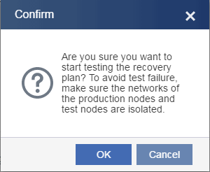
2. Click Start Testing.
3. In the dialog box that opens, read the prompt and then click OK.
To isolate the test environment from the production environment, you must edit the vSwitch and port profile mapping settings of the recovery site for the protection group protected by the recovery plan.
Figure 75 Confirming testing the recovery plan
4. Click the Recovery Tasks tab to view the state of the recovery task.
Figure 76 Recovery task state
5. Click the execution time link for the recovery task to view test details.
Figure 77 Viewing test details
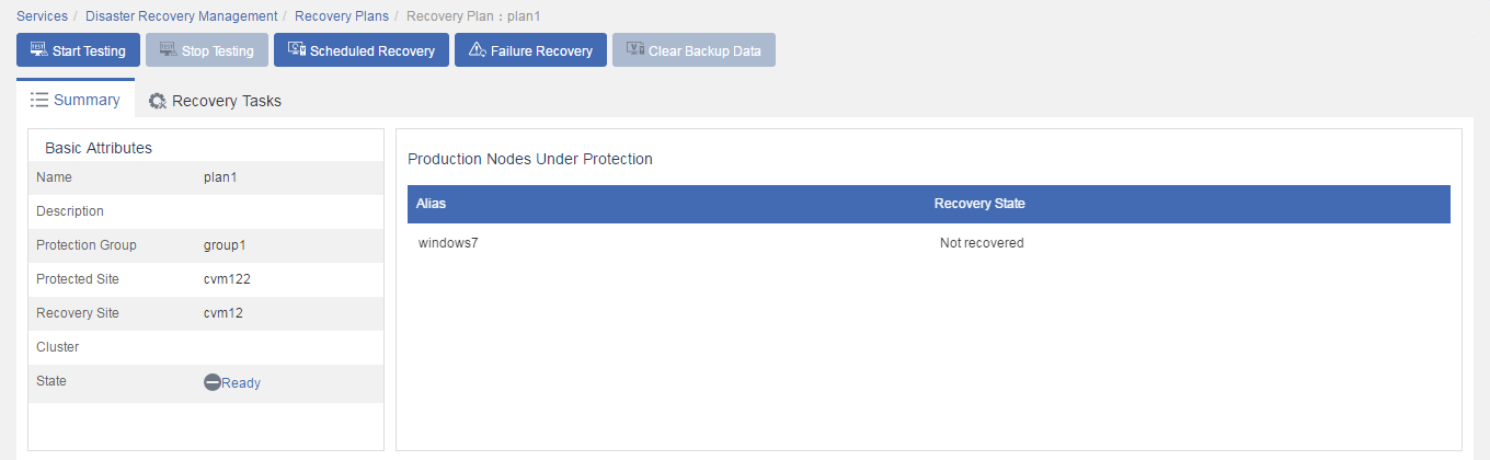
6. Verify that the protected VMs are running correctly on the protected site.
Figure 78 Protected VMs are running correctly on the protected site

7. Verify that the protected VMs have been restored on the hosts with mapped storage resources attached on the recovery site.
CVM selects optimal hosts from those attached to the destination storage pool to restore the VMs.
Figure 79 Viewing the test result on the recovery site
Finishing testing a recovery plan
1. Click Stop Testing on the recovery plan summary page.
Figure 80 Finishing testing a recovery plan
2. Click the Recovery Tasks tab to view the state of the recovery task.
Figure 81 Recovery task state
3. Click the execution time link for the recovery task to view test details.
Figure 82 Viewing test details
4. Verify that the protected VMs have been deleted from the recovery site, and the mapped storage resources have been removed.
Figure 83 Viewing the test result on the recovery site
5. Verify that the recovery plan is in Ready state.
To avoid communication issues, you must change the network settings in the mapped port profiles and vSwitches to the state before the test.
Figure 84 Recovery plan in Ready state
Running scheduled recovery
1. From the left navigation pane, select Services > Disaster Recovery Management > Recovery Plans > Recovery Plan Name.
2. Click Scheduled Recovery.
For heterogeneous clouds, shut down protected VMs or production nodes as prompted to avoid data errors.
Figure 85 Running scheduled recovery
3. Click the Recovery Tasks tab to view the state of the recovery task.
Figure 86 Recovery task state

4. Click the execution time link for the recovery task to view task details.
Figure 87 Viewing task details
5. Verify that the protected VMs have been shut down on the protected site.
Figure 88 Protected VMs have been shut down on the protected site

6. Verify that the protected VMs have been restored on the hosts with mapped resources attached on the recovery site.
Figure 89 Viewing the result on the recovery site
Clearing backup data
1. From the left navigation pane, select Services > Disaster Recovery Management > Recovery Plans > Recovery Plan Name.
2. Click Clear Backup Date.
Figure 90 Clearing backup data
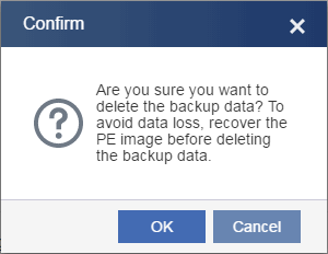
3. In the dialog box that opens, read the prompt and then click OK.
Figure 91 Confirming clearing backup data
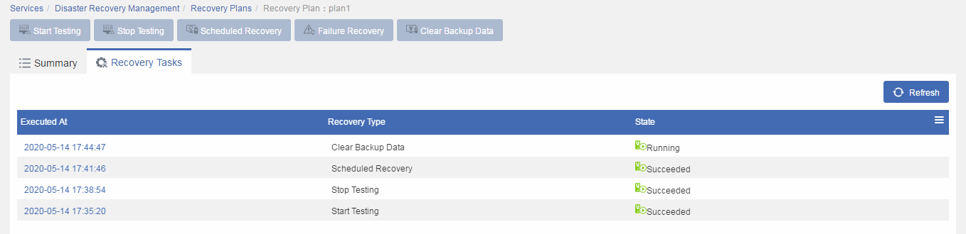
4. Click the Recovery Tasks tab to view the state of the recovery task.
Figure 92 Recovery task state
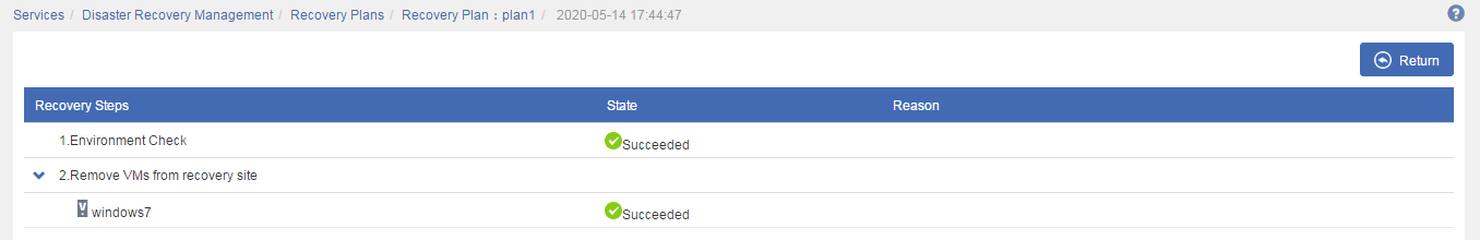
5. Click the execution time link for the recovery task to view task details.
Figure 93 Viewing test details
6. Verify that the protected VMs have been deleted from the recovery site, and the mapped storage resources have been removed.
Figure 94 Viewing the result on the recovery site
Running failure recovery
1. From the left navigation pane, select Services > Disaster Recovery Management > Recovery Plans > Recovery Plan Name.
2. Click Failure Recovery.
Figure 95 Running failure recovery
3. Click the Recovery Tasks tab to view the state of the recovery task.
Figure 96 Recovery task state
4. Click the execution time link for the recovery task to view task details.
Figure 97 Viewing task details
5. Verify that the protected VMs have been shut down on the protected site.
Figure 98 Protected VMs have been shut down on the protected site

6. Verify that the protected VMs have been restored on the hosts with mapped resources attached on the recovery site.
Figure 99 Viewing the result on the recovery site
Appendix A OS compatibility matrix for disk backup-based disaster recovery
Table 1 shows the operating systems that support the disaster recovery client.
Compatibility with Linux operating systems depends on the kernel version. For a Linux operating system whose kernel is not in the matrix, select a CDP driver with the closest kernel version. For example, you can install the CDP driver for Redhat4.7 x32 with kernel cdp_2.6.9-78.EL.ko on Redhat4.5 x32 with kernel 2.6.9-55.EL.
Table 1 OS compatibility matrix
|
Category |
Operating system version |
|
Windows |
Windows Server 2003 x86/x64 |
|
Windows Server 2008 x86/x64 |
|
|
Windows Server 2008 R2 x64 |
|
|
Windows Server 2012 x64 |
|
|
Windows Server 2012 R2 x64 |
|
|
Windows Server 2016 |
|
|
Red Hat |
Redhat 4.2 i386 (2.6.9-22ELsmp) |
|
Redhat 4.2 i386 (2.6.9-22.EL.ko) |
|
|
Redhat 4.3 i386 (2.6.9-34.21AXsmp.ko) |
|
|
Redhat 4.6 x64 (2.6.9-67.ELlargesmp_x64.ko) |
|
|
Redhat 4.7 x32 (2.6.9-78.EL.ko) |
|
|
Redhat 4.7 x32 (2.6.9-78.ELsmp.ko) |
|
|
Redhat 4.7 x64 (cdp_2.6.9-78.EL_x64.ko) |
|
|
Redhat 4.7 x64 (2.6.9-78.ELsmp_x64) |
|
|
Redhat 5 x32 series (2.6.18-8.el5.ko) |
|
|
Redhat 5 x64 series (2.6.18-8.el5_x64.ko) |
|
|
Redhat 6.0 x32 series (2.6.32-71.el6.i686) |
|
|
Redhat 6.0 x64 series (2.6.32-71.el6.x86_64) |
|
|
Redhat 6.2 x32 (2.6.32-220.el6.i686.ko) |
|
|
Redhat 6.2 x64 (2.6.32-220.el6.x86_x64.ko) |
|
|
Redhat 7.0 x64 (3.10.0-123.el7.x86_64) |
|
|
Redhat 7.1 x64 (3.10.0-229.el7.x86_64) |
|
|
Redhat 7.2 x64 (3.10.0-327.el7.x86_64) |
|
|
CentOS |
Centos 6 x32 series (2.6.32-71.el6.i686) |
|
Centos 6 x64 series (2.6.32-71.el6.x86_64) |
|
|
Centos 7.0 x64 (3.10.0-123.el7.x86_64) |
|
|
Centos 7.1 x64 (3.10.0-229.el7.x86_64) |
|
|
Centos 7.2 x64 (3.10.0-327.el7.x86_64) |
|
|
Oracle Linux |
OracleLinux-R6-U3-x64 (2.6.39-200.24.1.el6uek.x86_64.ko) |
|
Kylin |
Kylin-4.0-1E-desktop_20160401-final-x86_64 (3.16.0-23-generic) |
|
NeoKylin-Linux-Advanced-Server-6.7 (2.6.32-573.el6.x86_64) |
|
|
NeoKylin-sws-3.2(64) (2.6.32-220.2.1.2.ky3.2.x86_64) |
|
|
YHKylin-4.2-5-x86_64-server (2.6.32-431.29.2.3.ky3.1.x86_64) |
|
|
Suse |
SUSE Linux Enterprise Server 10 SP2 x86 (2.6.16.60-0.21-bigsmp) |
|
SUSE Linux Enterprise Server 10 SP2 x86 (2.6.16.60-0.21-default) |
|
|
SUSE Linux Enterprise Server 10 SP2 x64 (2.6.16.60-0.21-default) |
|
|
SUSE Linux Enterprise Server 10 SP2 x64 (2.6.16.60-0.21-smp) |
|
|
SUSE Linux Enterprise Server 10 sp3 x64 (2.6.16.60-0.54.5-smp_x64) |
|
|
SUSE Linux Enterprise Server 11 SP2 x64 (3.0.13-0.27-default) |
|
|
Suse Linux Enterprise Server 11 sp3 x86 (3.0.76-0.11-pae) |
|
|
Suse Linux Enterprise Server 11 sp3 x64 (3.0.76-0.11-default) |
|
|
Suse Linux Enterprise Server 11 sp3 x64 (3.0.101-0.31-default_x64) |
|
|
Suse Linux Enterprise Server 12 sp2 x64 (4.4.21-69-default_x64) |
|
|
Ubuntu |
Ubuntu-12.04 x64 (3.13.0-117-generic) |
|
Ubuntu-14.10 x64 (3.16.0-23-generic) |
Appendix B Configuring storage replication-based disaster recovery with storage arrays that do not SRAs
You must follow the restrictions and guidelines in "Configuring storage replication-based disaster recovery."
This example uses two HPE storage arrays.
To prepare storage:
1. Log in to the HP StoreVirtual Centralized Management Console.
2. In the left navigation tree, right-click Volumes and Snapshots, and then select Create volume.
3. Configure volume lun_srm and assign it to hosts on the protected site.
4. Right-click volume lun_srm, and then select Schedule to Remote Snapshot a Volume.
5. Configure the parameters.
Select a volume on the storage array of the recovery site as the remote volume. If no remote volume is available, you can configure the console to create a remote volume.
6. After data synchronization is finished, right-click remote volume volume lun_srm, and then select Edit Volume.
7. Promote volume lun_srm to a primary volume and assign it to hosts on the recovery site.
For the volume on the protected site to replicate data to the volume on the recovery site based on a snapshot policy, make sure the recovery site volume is in remote state.
Add the storage volumes configured in "Preparing storage" as shared file systems or block devices on CAS.
Configuring the protected site
1. Deploy host pools, clusters, and CVK hosts on CAS CVM.
2. From the left navigation pane, select Resources > Host Pool Name.
3. Click the Shared File Systems tab.
4. Click Add.
5. Add the primary LUN configured in "Preparing storage" a shared file system.
If you add the LUN as network storage, attach it to a host directly.
Figure 100 Configuring basic parameters for the shared file system
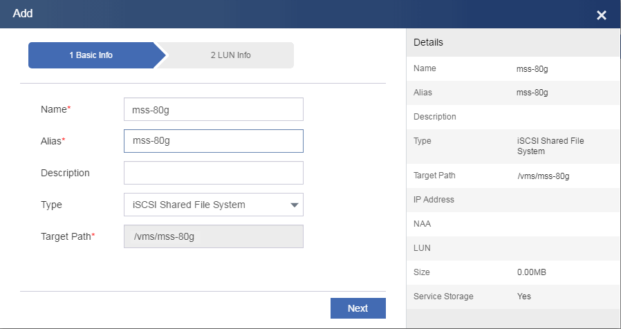
Figure 101 Configuring LUN settings for the shared file system
6. From the left navigation pane, select Resources > Host Pool Name > Cluster Name.
7. Click the Storage tab.
8. Click Add.
9. Attach the shared file system to hosts.
Figure 102 Attaching the shared file system to hosts
10. From the left navigation pane, select Cloud Resources > Host Pool Name > Cluster Name > Host Name.
11. Click Add VM.
12. Create a VM and attach the shared file system as a storage pool to the VM.
Figure 103 Configuring basic parameters for the VM
Restrictions and guidelines
A shared file system can contain only one storage volume (corresponds to a LUN).
After you attach storage resources to VMs on CAS, synchronize the backup volume with the primary volume before you perform data recovery.
Procedure
1. Deploy host pools, clusters, and CVK hosts on CAS CVM.
2. From the left navigation pane, select Resources > Host Pool Name.
3. Click the Shared File Systems tab.
4. Click Add.
5. Add the backup LUN configured in "Preparing storage" a shared file system.
Make sure the backup volume is in primary state.
You only need to add the shared file system on the host pool. You do not need to attach it to hosts.
Figure 104 Configuring basic parameters for the shared file system
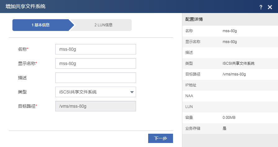
Figure 105 Configuring LUN settings for the shared file system
6. Log in to the storage management console and change the type of volume lun_srm_hp4530 from primary to remote.
The primary volume then will copy data to the backup volume. This allows the snapshot schedule to run correctly when the backup volume is a remote volume.
DRM configuration for storage arrays that support SRAs and do not support SRAs only differs in the following tasks:
· You do not need to add storage array managers when configuring sites.
· You must select non-SRA storage as the storage type when configuring storage resource mappings.
7. Log in to CAS CVM.
8. From the left navigation pane, select Services > Disaster Recovery Management > Sites.
9. Click Add Site.
10. Configure the local site.
Enter the IP address of the local CVM system. By default, the site added first is the local site (protected). The sites added subsequently are all remote sites.
11. Follow the steps to finish configuring the local site.
12. Add a remote site in the same way you add the local site.
Figure 106 Adding a remote site
Configuring a protection group
2. Click Add Protection Group.
3. Configure the name and description, select the protected and recovery sites, select host pools for the sites, and then click Next.
If you enable auto VM protection, a VM is automatically added to a protection group if it meets the following requirements:
¡ The storage pool, vSwitch, and port profile used by the VM belong to the protection group.
¡ No VM with the same name exists in the protection group.
¡ The VM does not use any local devices of a host, such as a floppy drive.
CAS does not protect the backup files and snapshots of the VMs in a protection group. When the VMs are recovered on the recovery site, their backup files and snapshots are deleted.
Figure 107 Configuring a protection group
4. To add a resource
mappings, drag the ![]() ,
, ![]() , or
, or ![]() icon.
icon.
You must select non-SRA storage as the storage type when configuring a storage resource mapping. You can create only shared file system mappings for storage arrays that do not support SRAs.
Figure 108 Resource mappings
5. Click Add VM for the protection group.
6. Select VMs and then click OK.
7. From the left navigation pane, select Services > Disaster Recovery Management > Recovery Plans.
8. Click Add Recovery Plan.
9. Enter a name and a description, select the protection group you have added, select a cluster for accommodating recovered VMs, and then click OK.
The recovery plan is in Initialize state after creation.
Figure 109 Configuring the recovery plan
1. Log in to the storage management console.
2. Right-click volume lun_srm, and then select Remote Snapshot.
3. Synchronize backup volume lun_srm_4530 with primary volume lun_srm.
4. After data synchronization is finished, edit volume lun_srm_4530 to promote it to a primary volume.
5. Log in to CAS CVM.
6. From the left navigation pane, select Services > Disaster Recovery Management > Recovery Plans > Recovery Plan Name.
7. Click Start Testing.
8. In the dialog box that opens, select an execution mode, and then click OK.
9. Click the Recovery Tasks tab to view the state of the recovery task.
10. Click the execution time link for the recovery task to view task details.
11. Click Stop Testing on the recovery plan summary page.
12. Click the Recovery Tasks tab to view the state of the recovery task.
13. Click the execution time link for the recovery task to view test details.
14. Log in to the storage management console.
15. Select the most recent snapshot for volume lun_srm_hp4530, right-click the snapshot, and then select Roll Back Volume.
16. Edit volume lun_srm_hp4530 to change its type to remote volume.
1. Log in to the storage management console.
2. Right-click volume lun_srm, and then select Remote Snapshot.
3. Synchronize volume lun_srm_hp4530 with volume lun_srm.
4. Log in to CAS CVM and shut down protected VMs.
5. Log in to the storage management console.
6. Right-click volume lun_srm, and then select Remote Snapshot.
7. Synchronize volume lun_srm_hp4530 with volume lun_srm.
8. After data synchronization is finished, edit volume lun_srm_hp4530 to promote it to a primary volume.
9. Log in to CAS CVM.
10. From the left navigation pane, select Services > Disaster Recovery Management > Recovery Plans > Recovery Plan Name.
11. Click Scheduled Recovery.
12. In the dialog boxes hat open, read the prompts, select an execution mode, and confirm running scheduled recovery.
13. Click the Recovery Tasks tab to view the state of the recovery task.
14. Click the execution time link for the recovery task to view task details.
Restrictions and guidelines
If the storage resources on the protected site are available, synchronize the storage resources on the protected and recovery sites before you run failure recovery.
Procedure
1. Log in to the storage management console.
2. Edit volume lun_srm_hp4530 to promote it to a primary volume.
3. From the left navigation pane, select Services > Disaster Recovery Management > Recovery Plans > Recovery Plan Name.
4. Click Failure Recovery.
5. In the dialog boxes that open, confirm storage configuration and select an execution mode.
6. Click the Recovery Tasks tab to view the state of the recovery task.
7. Click the execution time link for the recovery task to view task details.
1. Log in to the storage management console.
2. Edit volume lun_srm to change its type to remote volume.
3. Synchronize volume lun_srm with volume lun_srm_hp4530 by creating a remote snapshot for volume lun_srm_hp4530 to volume lun_srm.
4. Log in to CAS CVM and shut down the recovered VMs on the recovery site.
5. Log in to the storage management console.
6. Synchronize volume lun_srm with volume lun_srm_hp4530 by creating a remote snapshot for volume lun_srm_hp4530 to volume lun_srm.
7. After data synchronization is finished, edit volume lun_srm to promote it to a primary volume.
8. Log in to CAS CVM.
9. From the left navigation pane, select Services > Disaster Recovery Management > Recovery Plans > Recovery Plan Name.
10. Click Reverse Recovery.
11. In the dialog boxes that open, confirm storage configuration and confirm running reverse recovery.
12. Click the Recovery Tasks tab to view the state of the recovery task.
13. Click the execution time link for the recovery task to view task details.
14. Log in to the storage management console.
15. Edit volume lun_srm_hp4530 to change its type to remote volume.
