Country / Region
- Products and Solutions
- Industry Solutions
- Services
- Support
- Training & Certification
- Partners
- About Us
- Contact Sales
- Become a Partner
-
 Login
Login
Country / Region
SPB Technology White Paper
Copyright © 2018 New H3C Technologies Co., Ltd. All rights reserved. No part of this manual may be reproduced or transmitted in any form or by any means without prior written consent of New H3C Technologies Co., Ltd. The information in this document is subject to change without notice. |
|
Overview
Technical background
Layer 2 interconnect among sites must satisfy the following requirements:
Site independence—Problems (for example, broadcast storms) in a site are not spread to other sites, and the topology of each site does not affect or depend on each other.
Transport independence—No special requirements are posed on the inter-site data transmission techniques, site locations, and service provider networks. The most common technologies, for example, IP, are used in the core network.
High availability—Multi-homing is used to provide redundant access and the loop avoidance mechanism.
Link efficiency—The inter-site traffic, including multicast traffic and broadcast traffic, must be fully optimized to save the bandwidth, and be load-balanced when redundant links exist.
Site transparency—The data center interconnect does not depend on the topology of a site or pose special requirements on the site topology.
Easy management and maintenance—Simple techniques are used to interconnect sites, so that you can quickly add and cut down sites. Simple techniques are used on the BEBs to minimize the change to the networks of the current sites and to ensure traffic forwarding during the deployment.
Benefits
IEEE 802.1aq Shortest Path Bridging (SPB) enables multipath routing in an Ethernet mesh network by using IS-IS as the control protocol. The technology allows all paths to be active, supports equal cost paths, and provides shortest path forwarding in an Ethernet mesh network. IEEE 802.1aq SPB provides faster convergence, higher link efficiency, and larger Layer 2 topologies than conventional spanning tree protocols such as MSTP. SPB delivers the following benefits:
Network virtualization.
Fast service deployment and easy network maintenance—The services are separate from the core network and deployed only on the BEBs. The newly added links and devices in the core network do not need to be aware of services.
Fast failover—Basic network protocols based on link status provide fast failover.
Dual-homing networks—Traditional switches can access the SPB network through redundancy backup.
Optimized bandwidth usage—SPB provides load balancing based on equal-cost multi-path routing and supports shortest path forwarding for unicast traffic and multicast traffic, well optimizing the bandwidth utilization.
Smooth upgrading—SPB supports smoothly upgrading the current network without upgrading hardware, and provides plenty of compliant protocols and standards.
SPB implementation
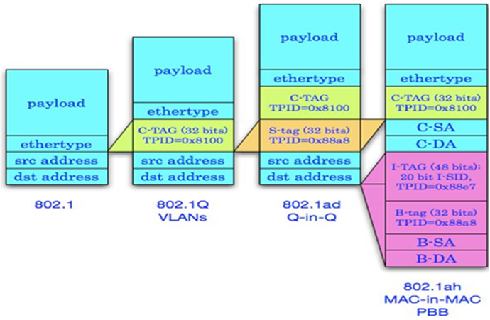
Shortest path bridging MAC mode (SPBM) is one bridging method of IEEE 802.1aq SPB. This method encapsulates Ethernet frames into MAC-in-MAC frames in compliance with IEEE 802.1ah PBB.
Concepts
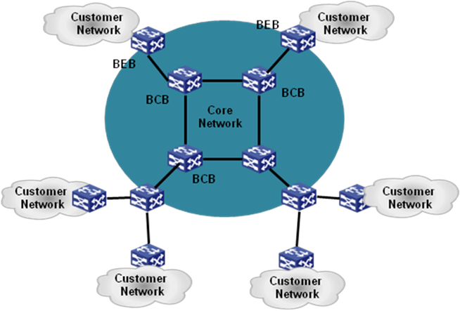
Backbone link/access link—A link that connects a backbone core bridge (BCB) to a backbone edge bridge (BEB) is a backbone link. A link that connects a BEB to a customer network is called an access link. After the frames from the customer network are encapsulated in MAC-in-MAC frames, they are forwarded along the corresponding backbone link of the BEB. After the MAC-in-MAC frames from the SPBM network are decapsulated, they are forwarded out along the corresponding access link of the BEB according to the customer MAC address.
BCB—BCBs are core nodes of an SPBM network. BCBs forward MAC-in-MAC frames based on the B-MAC and B-VLAN. They do not learn customer MAC (C-MAC) addresses. This makes the SPBM network more expandable.
BEB—BEBs are edge nodes of the SPBM network. BEBs encapsulate customer frames into MAC-in-MAC frames before forwarding them to the SPBM network. BEBs also decapsulate MAC-in-MAC frames before sending them to a customer site.
B-MAC and B-VLAN—Backbone MAC addresses (B-MACs) are bridge MAC addresses associated with SPBM bridges. Backbone VLANs (B-VLANs) are VLANs assigned by the service provider for transmitting customer traffic on the SPBM network.
For customer frames to be transmitted across an SPBM network, the ingress BEB encapsulates them in MAC-in-MAC format. In the outer frame header, the source MAC address is a B-MAC of the ingress BEB, and the destination MAC is a B-MAC of the egress BEB. All devices in the SPBM network forward the MAC-in-MAC frames based on the destination B-MAC and B-VLAN.
Customer network port and provider network port—On a BEB, a customer network port (CNP) connects to a customer site and a provider network port (PNP) connects to the SPBM network.
Ethernet service instance—An Ethernet service instance provides forwarding service for a set of customer VLANs (C-VLANs). To extend C-VLANs across customer sites over an SPBM network, you must configure Ethernet service instances on BEBs' customer edge ports and map them to SPB VSIs.
LSDB—A link state database (LSDB) contains the states of all links in an SPBM network.
MAC-in-MAC frame—A frame encapsulated in MAC-in-MAC format is called a MAC-in-MAC frame. When encapsulating a customer frame into a MAC-in-MAC frame, an ingress BEB uses its own B-MAC as the source MAC address and the B-MAC of the egress BEB as the destination MAC address.
PW—Pseudo wires (PWs) are MAC-in-MAC tunnels established over the SPBM network for transmitting customer traffic. PWs are established between BEBs. BCBs do not set up PWs.
SPB VSI and I-SID—An SPB virtual switch instance (SPB VSI) provides MAC-in-MAC tunnel service for Ethernet service instances. An SPB VSI acts as a virtual switch. It has all functions of a conventional Ethernet switch, including source MAC address learning, MAC address aging, and flooding. Each SPB VSI is uniquely identified by an I-SID.
Network model
After the BCBs are deployed, you do not need to change them. If you want to add new SPB VSIs, you only need to deploy the SPB VSIs on the BEBs.
A customer network can access the SPBM network through VLANs or VPNs.
Figure 2 SPBM access methods
In the VLAN access mode, the whole network organizes users by VLAN. The SPB VSIs are used as management zones carrying different VLANs. You can deploy SPB VSIs and VLANs on the network access points rather than on backbone nodes. This configuration procedure is simple.
In the VPN access mode, BEBs are the edge devices of the VPN, and the SPB VSIs identify network users. Different users access the core network through different physical ports. Deploy the SPB VSIs and access virtual ports on the network access points, and you do not need to deploy them on the backbone nodes. This mode supports VLAN mapping and multi-user access, and the configuration is complicated.
Mechanism
Control plane fundamentals
The SPBM control plane provides a very simple operation and maintenance mode that runs only the ISIS-SPB protocol. This reduces the deployment cost.
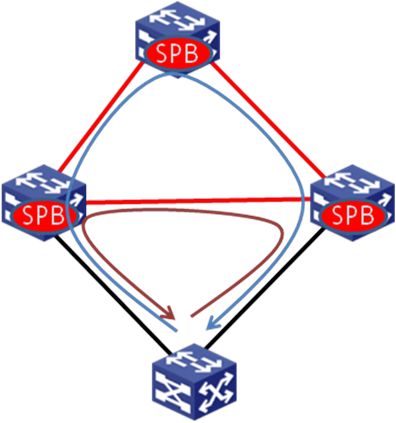
Topology discovery procedure
Figure 3 Network running ISIS-SPB
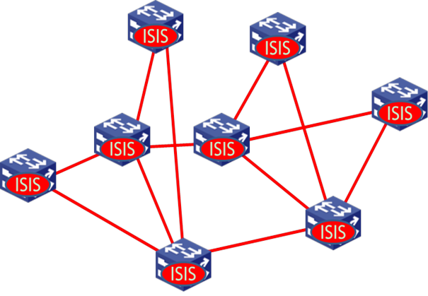
Before the shortest path tree calculation, the network topology must be discovered first. ISIS-SPB runs on all devices of the SPBM network. These devices establish point-to-point protocol adjacencies between each other and exchange topology information. Each device has a node ID for topology advertisement. Additionally, each device has at least one B-MAC, which is used as the destination MAC address of frames that the other devices send to the local device through the SPBM network.
B-VLAN and ECT advertisement
SPBM traffic is carried on B-VLANs. A B-VLAN can carry one or multiple SPB VSIs. Each B-VLAN has a unique equal-cost tree (ECT), which implements load balancing among different B-VLANs. The ISIS-SPB protocol exchanges B-VLAN to ECT algorithm mappings between neighbors through IIH packets, and synchronizes the B-VLAN to ECT algorithm mappings throughout the network through LSPs.
MAC address advertisement
The ISIS-SPB protocol advertises only the B-MACs of the core network. Customer MAC addresses (C-MACs) are learned only on the BEBs and are not advertised to the core network.
After the ISIS-SPB protocol establishes adjacencies, each node advertises its B-MAC through LSPs. Eventually, the LSDBs of all nodes are synchronized. Each node runs SPF to calculate the shortest path from itself to each of the other nodes. Then each BEB can advertise its local C-MAC address entries to other BEBs.
If a node is removed from the network, the adjacent devices of the removed node will trigger the ISIS-SPB protocol on the control plane to update MAC addresses for the other devices to delete the removed MAC address.
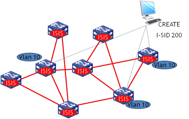
New service distribution
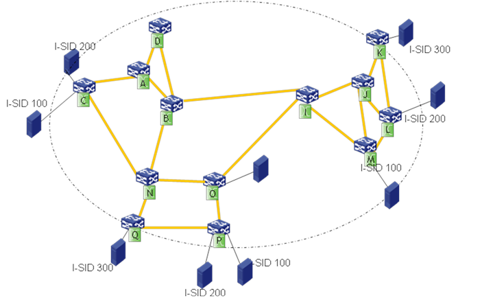
If you deploy a new SPB VSI, each member BEB uses ISIS-SPB to advertise the B-MAC and I-SID information and declares itself as the member of the I-SID. In this example, B-VLAN 10 is assigned to I-SID 200, and three nodes are in I-SID 200.
Figure 4 SPBM I-SID advertisement
The I-SID and B-MAC advertisement process is shown Figure 5.
Figure 5 SPBM B-MAC/I-SID advertisement
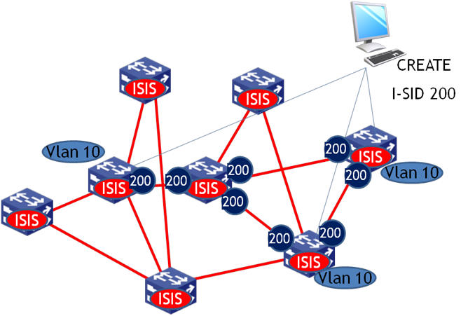
After the B-MAC/I-SID information is flooded through LSPs, each node in B-VLAN 10 calculates the FDB according to the ISIS-SPB shortest path tree. Traditional MAC flooding and learning mechanisms are not used in B-VLANs, and the FDB is completely obtained through the ISIS-SPB protocol.
Data plane fundamentals
Unicast traffic
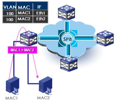
Once the control plane of each core network device establishes the ISIS-SPB adjacencies and exchanges the MAC reachability information, traffic can be forwarded between sites. For an intra-site known unicast frame, the BEB performs typical MAC address table lookup. As shown in Figure 6, host1 (MAC1) sends an Ethernet frame to host2 (MAC2). When the ingress BEB receives the Ethernet frame on interface Eth1, the interface learns the MAC address of the Ethernet frame into the MAC address table of Eth1, looks up the MAC address table to get the outgoing interface Eth2, and sends the Ethernet frame out of interface Eth2.
Figure 6 Intra-site Layer 2 traffic forwarding
The inter-site Layer 2 traffic forwarding flow is different from the traditional Layer 2 forwarding flow, as shown in Figure 7.
Figure 7 Inter-site Layer 2 traffic forwarding
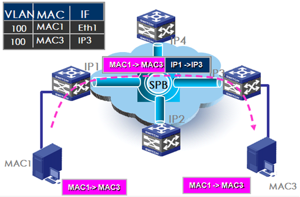
The traffic forwarding flow is as follows:
1. When an ingress BEB receives an Ethernet frame, it performs the following tasks:
a. Assigns the frame to the correct SPB VSI based on the outer VLAN.
b. Learns the source MAC address.
c. Looks up the destination MAC address in the MAC address table of the SPB VSI.
2. If the outgoing interface is a transport network port, the ingress BEB encapsulates the original Ethernet frame in MAC-in-MAC format. The source MAC in the outer Ethernet header is the ingress BEB's MAC address, the destination MAC address is the MAC address of the egress BEB, and the B-tag contains the B-VLAN of the SPB VSI.
3. The ingress BEB sends the MAC-in-MAC frame to the core network through the provider network port.
4. The egress BEB decapsulates the packet and removes the outer Ethernet header.
5. The egress BEB looks up the destination MAC address in the inner header for a local outgoing interface, and sends the Ethernet frame out of the outgoing interface to the destination host.
Multicast traffic
SPBM floods unknown customer unicast, unknown customer multicast, and broadcast as multicast traffic. SPBM supports the following replication methods for multicast:
Head-end replication—Replicates frames at the ingress BEB for frames to enter the SPBM network. This method is suitable for SPB VSIs that have sparse multicast traffic. It does not require BCBs to maintain multicast FDB entries.
Tandem replication—Replicates frames only at the node where the shortest path tree forks. This method is suitable for SPB VSIs that have dense multicast traffic. It requires BCBs to maintain multicast FDB entries.
You can select head-end replication or tandem replication according to the network conditions and the size of multicast traffic. Figure 8 shows how head-end replication works.
Figure 8 Multicast traffic model—head-end replication
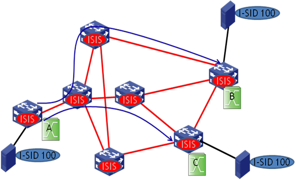
In tandem replication, the distribution of an I-SID on BEBs indicates the transmission range of traffic from the I-SID in the SPBM network. For example, as shown in Figure 9, device A, device B, and device C have I-SID 100. The devices form a multicast group to forward multicast traffic of I-SID 100. Each SPBM node has a multicast address for the SPB VSI. Each BEB calculates a multicast tree with itself as the source to forward multicast traffic.
Figure 9 Multicast traffic model—tandem replication
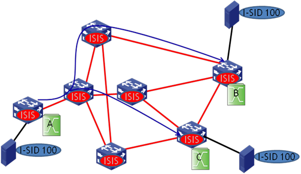
As shown in Figure 9, device A of I-SID 100 has a multicast source attached, and device B and device C have the receivers of the multicast source. When the ISIS-SPB protocol completes the calculation on BCBs, the multicast entries are issued to the chip, and the multicast traffic is replicated and then forwarded to the receivers along the blue line.
Tunneling encapsulation format
SPBM uses the standard 802.1ah encapsulation. BEBs perform the tunneling encapsulation for the frames entering the SPBM network. They add the B-MAC, B-VLAN, and I-SID to the frames, and send them to the core network. In the core network, SPBM forwards tunneled frames according to the B-VLAN and B-MAC. When the tunneled frames leave the core network, BEBs remove the tunneling encapsulation and send the original frames to their attached customer network sites.
Figure 10 SPBM data frame encapsulation format
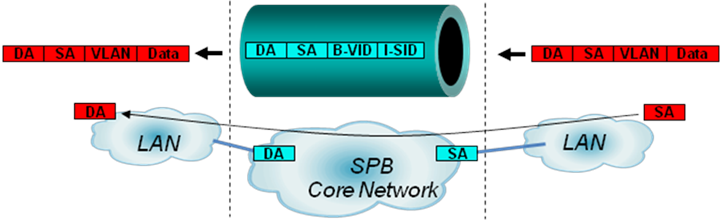
Finally, the length of the frame transmitted in the core network is added by 22 bytes. The SPBM solution does not define the MTU discovery function. Before deploying SPBM, make sure the MTU of the core network is larger than the maximum length of tunneled frames.
Dual-homing
To implement high reliability and avoid single-point failures for network devices, you can use two BEBs to connect a customer site to the core network. Loops might exist in the dual-homing site, as shown in Figure 11.
Figure 11 Loops caused by dual-homing
The IRF technology virtualizes multiple physical devices into a single logical device. You can use IRF and multichassis link aggregation to eliminate loops, as shown in Figure 12.
Figure 12 Dual-homing access through IRF

VLAN mapping
The sites of a data center might have different VLAN deployment plans. The same service might be deployed to different VLANs at two sites. For communication between these VLANs without changing the original networks of the sites, you must configure VLAN mapping on the BEBs.
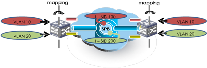
SPBM binds C-VLANs to I-SIDs on the BEB, so that C-VLANs can be distributed in different sites. A network administrator only needs to deploy VLAN mappings on the BEB. Then, the SPBM network can automatically establish VLAN-based connections for users. In Figure 13, VLAN 10 is mapped to I-SID 100, and VLAN 20 is mapped to I-SID 200.
Figure 13 VLAN-to-I-SID mapping
Technical specifications
The SPBM specifications defined in the current software version are as follows:
The number of SPBM nodes: 512 in head-end replication mode and 256 in tandem replication mode.
The number of B-VLANs: 32.
The number of I-SIDs: 8K.
The number of neighbors for a single device: 255.
SPBM application scenarios
Data center
Most data centers use the layered hierarchical design method. In this method, node redundancy is deployed at each layer. At the distribution layer, service processing devices or modules, such as SLBs, firewalls, IPSs, are deployed also with redundancy. The distribution devices form the boundaries between Layer 2 broadcast domain and Layer 3 routed network.
Enterprises typically apply the same network design to their geographically dispersed data centers and deploy the same applications in the data centers for high availability and ease of dynamic resources management. A practice that has been widely used is to deploy modular data centers, such as HP PODs. Each modular data center (or POD) includes a set of servers, racks, access switches, and distribution switches. Data center expansion is to add PODs as needed. The PODs are connected through core layer devices.
Figure 14 shows a generic SPBM deployment model for data centers.
Figure 14 General SPBM deployment model in a data center
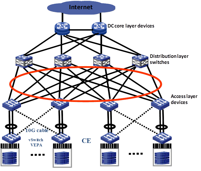
vSwitches access the network through 10-GE links at Layer 2. SPBM switches are deployed on the access layer and distribution layer. Up to 16 equal-cost paths are supported.
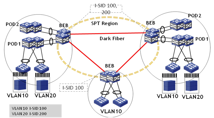
Add independent edge-layer devices to the data center for Layer 2 data center interconnection. The edge layer supports device redundancy for improving the reliability. Distribution-layer devices of multiple PODs in the data center connect to BEBs through Layer 2 links, so that a large-scaled forwarding domain is formed between PODs of different data center sites.
Figure 15 Data center interconnection model
Multi-tenancy MAN
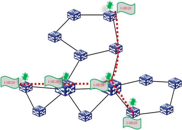
As shown in Figure 16, the SPBM network can provide access services for multiple tenants, for example, education organizations, government agencies, and fire fighting departments. These tenants are distributed in different locations of a city, and are in the same network for servicing. The core network runs two data centers which are transparently interconnected by the SPBM network to implement server virtualization.
All departments share the same core network. However, each department performs operations in only their own security zone. Departments cannot communicate with each other without penetrating the firewall in the data center.
Figure 16 Multi-tenant network deployment model
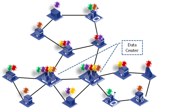
Figure 16 shows a typical network for public departments of a city. These departments are located in different areas of the city, and all data is saved in the two data centers. These departments are interconnected through the SPBM network. The SPBM links form the core network of the campus. Each node has one or two devices accessing the core network. The interconnecting links are bare fibers, E-line services, CWDM, DWDM, or other links that support transmitting Ethernet frames. The two data centers deploy virtualized servers and storage devices, and assign different SPB VSIs to different departments, so that the users of the same department can communicate with each other at Layer 2 and users of different departments are isolated. For example, I-SID 20 is allocated to the education department. You only need to deploy the I-SID on the related access devices rather than other nodes. Then, the education department uses the logical Layer 2 network identified by I-SID 20, and the traffic will not be flooded to unrelated devices.
Figure 17 Logical network of the multi-tenant education department