- Table of Contents
-
- 10-Security Configuration Guide
- 00-Preface
- 01-AAA Configuration
- 02-802.1X Configuration
- 03-MAC Authentication Configuration
- 04-Portal Configuration
- 05-Password Control Configuration
- 06-Public Key Configuration
- 07-IPsec Configuration
- 08-SSH Configuration
- 09-Packet-Filter Firewall Configuration
- 10-ALG Configuration
- 11-Session Management Configuration
- 12-TCP and ICMP Attack Protection Configuration
- 13-IP Source Guard Configuration
- 14-ARP Attack Protection Configuration
- 15-URPF Configuration
- 16-COPS Configuration
- 17-FIPS Configuration
- 18-PKI Configuration
- Related Documents
-
| Title | Size | Download |
|---|---|---|
| 10-ALG Configuration | 162.50 KB |
ALG overview
The Application Level Gateway (ALG) feature is used to process application layer packets.
Usually, Network Address Translation (NAT) translates only IP address and port information in packet headers; it does not analyze fields in application layer payloads. However, the packet payloads of some protocols may contain IP address or port information, which, if not translated, may cause problems. For example, a File Transfer Protocol (FTP) application involves both data connection and control connection, and data connection establishment dynamically depends on the payload information of the control connection. ALG can process the payload information to make sure that the data connections can be established.
ALG can work with NAT to implement the following functions:
· Address translation
Resolves the source IP address, port, protocol type (TCP or UDP), and remote IP address information in packet payloads.
· Data connection detection
Extracts information required for data connection establishment and establishing data connections for data exchange.
· Application layer status checking
Inspects the status of the application layer protocol in packets. If the status is right, updating the packet state machine and performing further processing; otherwise, dropping packets with incorrect states.
Support for the above functions depends on the application layer protocol. ALG can process packets of the following protocols:
· Domain Name System (DNS)
· FTP
· GPRS Tunneling Protocol (GTP)
· H.323, including Registration, Admission, Status (RAS), H.225, and H.245
· Internet Control Message Protocol (ICMP)
· Internet Locator Service (ILS)
· MSN/QQ
· Network Basic Input/Output System (NBT)
· Point-to-Point Tunneling Protocol (PPTP)
· Real Time Streaming Protocol (RTSP)
· Skinny Client Control Protocol (SCCP)
· Session Initiation Protocol (SIP)
· SQLNET (a language in Oracle)
· Trivial File Transfer Protocol (TFTP)
The following describes the operation of an ALG-enabled router, taking FTP as an example. As shown in Figure 1, the host on the external network accesses the FTP server on the internal network in passive mode through the ALG-enabled router.
Figure 1 Network diagram for ALG-enabled FTP application in passive mode
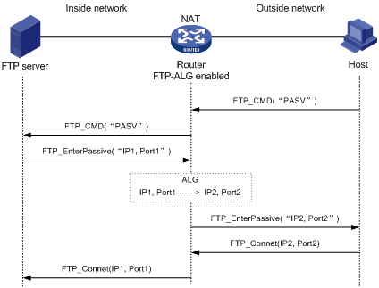
The communication process includes the following stages:
1. Establishing a control connection
The host sends a TCP connection request to the server. If a TCP connection is established, the server and the host enter the user authentication stage.
2. Authenticating the user
The host sends the server an authentication request, which contains the FTP commands (user and password) and the contents.
When the request passes through the ALG-enabled router, the commands in the payload of the packet will be resolved and used to check whether the state machine transition is going on correctly. If not, the request will be dropped. In this way, ALG protects the server against clients that send packets with state machine errors or log into the server with illegal user accounts.
An authentication request with a correct state is forwarded by the ALG-enabled router to the server, which authenticates the host according to the information in the packet.
3. Establishing a data connection
If the host passes the authentication, a data connection is established between it and the server. If the host is accessing the server in passive mode, the data connection process is different. In passive mode, the server sends the host a PASV response that uses its private network address and port number (IP1, Port1). When the response arrives at the ALG-enabled router, the router resolves the packet and translates the server’s private network address and port number into the server’s public network address and port number (IP2, Port2) respectively. Then, the router uses the public network address and port number to establish a data connection with the host.
4. Exchanging data
The host and the FTP server exchange data through the established data connection.
Enabling ALG
To enable ALG:
|
Step |
Command |
Remarks |
|
1. Enter system view. |
system-view |
N/A |
|
2. Enable ALG. |
alg { all | dns | ftp | h323 | ils | msn | nbt | qq | rtsp | sccp | sip | sqlnet | tftp } |
Optional. Enabled for all protocols by default The tftp keyword is not supported. |
Configuring a port mapping
To configure a port mapping:
|
Step |
Command |
Remarks |
|
1. Enter system view. |
system-view |
N/A |
|
2. Configure a mapping between a port and an application protocol. |
port-mapping application-name port port-number [ acl acl-number ] |
Optional. The source field of the ACL rule must be the public address of the internal server, that is, the address for external users to use to access the internal server. |
Displaying ALG
|
Task |
Command |
Remarks |
|
Display port mapping information. |
display port-mapping [ application-name | port port-number ] [ | { begin | exclude | include } regular-expression ] |
Available in any view |
ALG configuration examples
|
|
NOTE: The following examples describe only ALG-related configurations, assuming that other required configurations on the server and client have been done. |
FTP ALG configuration example
Network requirements
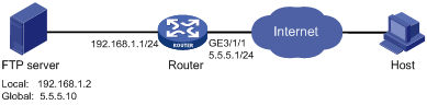
As shown in Figure 2, a company uses the private network segment 192.168.1.0/24, and has four public network addresses: 5.5.5.1, 5.5.5.9, 5.5.5.10, and 5.5.5.11. The company wants to provide FTP services to the outside.
Configure NAT and ALG on the router so that hosts on the external network can access the FTP server on the internal network.
Configuration procedure
# Configure the address pool and ACL.
<Router> system-view
[Router] nat address-group 1 5.5.5.9 5.5.5.11
[Router] acl number 2001
[Router-acl-basic-2001] rule permit
[Router-acl-basic-2001] quit
# Enable ALG for FTP.
[Router] alg ftp
# Configure NAT.
[Router] interface GigabitEthernet 3/1/1
[Router-GigabitEthernet3/1/1] nat outbound 2001 address-group 1
# Configure a NAT service interface binding.
[Router] interface nat 5/0/1
[Router-NAT5/0/1] nat binding interface GigabitEthernet 3/1/1
[Router-NAT5/0/1] quit
# Configure the internal FTP server.
[Router] interface GigabitEthernet 3/1/1
[Router-GigabitEthernet3/1/1] nat server protocol tcp global 5.5.5.10 ftp inside 192.168.1.2 ftp
SIP/H.323 ALG configuration example
|
|
NOTE: H.323 ALG configuration is similar to SIP ALG configuration. The following takes SIP ALG configuration as an example. |
Network requirements
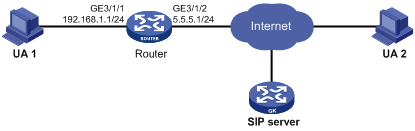
As shown in Figure 3, a company uses the private network segment 192.168.1.0/24, and has four public network addresses: 5.5.5.1, 5.5.5.9, 5.5.5.10, and 5.5.5.11. SIP UA 1 is on the internal network and SIP UA 2 is on the outside network.
Configure NAT and ALG on the router so that SIP UA 1 and SIP UA 2 can communicate by using their aliases, and SIP UA 1 selects an IP address from the range 5.5.5.9 to 5.5.5.11 when registering with the SIP server on the external network.
Configuration procedure
# Configure the address pool and ACL.
<Router> system-view
[Router] nat address-group 1 5.5.5.9 5.5.5.11
[Router] acl number 2001
[Router-acl-basic-2001] rule permit source 192.168.1.0 0.0.0.255
[Router-acl-basic-2001] rule deny
[Router-acl-basic-2001] quit
# Configure NAT.
[Router] interface GigabitEthernet 3/1/2
[Router-GigabitEthernet3/1/2] nat outbound 2001 address-group 1
[Router-GigabitEthernet3/1/2] quit
# Configure a NAT service interface binding.
[Router] interface nat 5/0/1
[Router-NAT5/0/1] nat binding interface GigabitEthernet 3/1/2
[Router-NAT5/0/1] quit
NBT ALG configuration example
Network requirements
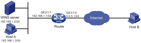
As shown in Figure 4, a company using the private network segment 192.168.1.0/24 wants to provide NBT services to the outside.
Configure NAT and ALG on the router so that Host A uses 5.5.5.9 as its external IP address, the WINS server uses 5.5.5.10 as its external IP address, and Host B can access the WINS server and Host A by using host names.
Configuration procedure
# Configure a static NAT entry.
<Router> system-view
[Router] interface nat 5/0/1
[Router-NAT5/0/1] nat static 192.168.1.3 5.5.5.9
[Router-NAT5/0/1] quit
# Enable ALG for NBT.
[Router] alg nbt
# Configure NAT.
[Router] interface GigabitEthernet 3/1/2
[Router-GigabitEthernet3/1/2] nat outbound static
[Router-GigabitEthernet3/1/2] quit
# Configure the internal WINS server.
[Router-GigabitEthernet3/1/2] nat server protocol udp global 5.5.5.10 137 inside 192.168.1.2 137
[Router-GigabitEthernet3/1/2] nat server protocol udp global 5.5.5.10 138 inside 192.168.1.2 138
[Router-GigabitEthernet3/1/2] nat server protocol tcp global 5.5.5.10 139 inside 192.168.1.2 139
[Router-GigabitEthernet3/1/2] quit
# Configure a NAT service interface binding.
[Router] interface nat 5/0/1
[Router-NAT5/0/1] nat binding interface GigabitEthernet 3/1/2
[Router-NAT5/0/1] quit