- Table of Contents
- Related Documents
-
| Title | Size | Download |
|---|---|---|
| 02-MPLS TE Configuration | 914.9 KB |
Contents
Traffic engineering and MPLS TE
MPLS TE configuration task list
Configuring MPLS TE basic capabilities
Creating MPLS TE tunnel over static CR-LSP
Configuring MPLS TE tunnel with dynamic signaling protocol
Configuring RSVP-TE advanced features
Configuring traffic forwarding
Configuring traffic forwarding tuning parameters
Configuring BFD for an MPLS TE tunnel
Configuring periodic LSP tracert for an MPLS TE tunnel
Configuring protection switching
Displaying and maintaining MPLS TE
MPLS TE configuration examples
MPLS TE using static CR-LSP configuration example
MPLS TE tunnel using RSVP-TE configuration example
Configuration example of inter-AS MPLS TE tunnel using RSVP-TE
RSVP-TE GR configuration example
MPLS RSVP-TE and BFD cooperation configuration example
MPLS TE using CR-LDP configuration example
CR-LSP backup configuration example
IETF DS-TE configuration example
MPLS LDP over MPLS TE configuration example
MPLS TE in MPLS L3VPN configuration example
Swicthback fails to occur when the main tunnel resumes
MPLS TE overview
Traffic engineering and MPLS TE
Let us get familiar with traffic engineering (TE) before going on to MPLS-TE.
Network congestion is one of the major problems that can degrade your network backbone performance. It may occur either when network resources are inadequate or when load distribution is unbalanced. TE is intended to avoid the latter situation where partial congestion may occur as the result of inefficient resource allocation.
TE can make best utilization of network resources and avoid non-even load distribution by real-time monitoring traffic and traffic load on each network elements to dynamically tune traffic management attributes, routing parameters and resources constraints.
The performance objectives associated with TE can be either of the following:
· Traffic oriented. These are performance objectives that enhance Quality of Service (QoS) of traffic streams, such as minimization of packet loss, minimization of delay, maximization of throughput and enforcement of service level agreement (SLA).
· Resource oriented. These are performance objectives that optimize resources utilization. Bandwidth is a crucial resource on networks. Efficiently managing it is one major task of TE.
To implement TE, you can use interior gateway protocols (IGPs) or Multiprotocol Label Switching (MPLS).
Because IGPs are topology-driven and consider only network connectivity, they fail to present some dynamic factors such as bandwidth and traffic characteristics.
This IGP disadvantage can be repaired by using an overlay model, such as IP over ATM or IP over FR. An overlay model provides a virtual topology above the physical network topology for a more scalable network design. It also provides better traffic and resources control support for implementing a variety of traffic engineering policies.
Despite all the benefits, overlay models are not suitable for implementing traffic engineering in large-sized backbones because of their inadequacy in extensibility. In this sense, MPLS TE is a better traffic engineering solution for its extensibility and ease of implementation.
MPLS is better than IGPs in implementing traffic engineering for the following reasons:
· MPLS supports explicit LSP routing.
· LSP routing is easy to manage and maintain compared with traditional packet-by-packet IP forwarding.
· Constraint-based Routed Label Distribution Protocol (CR-LDP) is suitable for implementing a variety of traffic engineering policies.
· MPLS TE uses less system resources compared with other traffic engineering implementations.
MPLS TE combines the MPLS technology and traffic engineering. It delivers these benefits:
· Reserve resources by establishing LSP tunnels to specific destinations. This allows traffic to bypass congested nodes to achieve appropriate load distribution.
· When network resources are insufficient, MPLS TE allows bandwidth-hungry LSPs or critical user traffic to occupy the bandwidth for lower priority LSP tunnels.
· In case an LSP tunnel fails or congestion occurs on a network node, MPLS TE can provide route backup and Fast Reroute (FRR).
With MPLS TE, a network administrator can eliminate network congestion simply by creating some LSPs and congestion bypass nodes. Special offline tools are also available for the traffic analysis performed when the number of LSPs is large.
Basic concepts of MPLS TE
LSP tunnel
On an LSP, after packets are labeled at the ingress node, the packets are forwarded based on label. The traffic thus is transparent to the transits nodes on the LSP. In this sense, an LSP can be regarded as a tunnel.
MPLS TE tunnel
Reroute and transmission over multiple paths may involve multiple LSP tunnels. A set of such LSP tunnels is called a traffic engineered tunnel (TE tunnel).
MPLS TE implementation
MPLS TE mainly accomplishes the following functions:
· Static Constraint-based Routed LSP (CR-LSP) processing to create and remove static CR-LSPs. The bandwidth of a static CR-LSP must be configured manually.
· Dynamic CR-LSP processing to handle three types of CR-LSPs: basic CR-LSPs, backup CR-LSPs and fast rerouted CR-LSPs.
Static CR-LSP processing is simple, while dynamic CR-LSP processing involves four phrases: advertising TE attributes, calculating paths, establishing paths, and forwarding packets.
Advertising TE attributes
MPLS TE must be aware of dynamic TE attributes of each link on the network. This is achieved by extending link state-based IGPs such as OSPF and IS-IS.
OSPF and IS-IS extensions add to link states such TE attributes as link bandwidth, color, among which maximum reservable link bandwidth and non-reserved bandwidth with a particular priority are most important.
Each node collects the TE attributes of all links on all routers within the local area or at the same level to build up a TE database (TEDB).
Calculating paths
Link state-based routing protocols use Shortest Path First (SPF) to calculate the shortest path to each network node.
In MPLS TE, the Constraint-based Shortest Path First (CSPF) algorithm is used to calculate the shortest, TE compliant path to a node. It is derived from SPF and makes calculation based on two conditions:
· Constraints on the LSP to be set up with respect to bandwidth, color, setup/holding priority, explicit path and other constraints. They are configured at the LSP ingress.
· TEDB
CSPF first prunes TE attribute incompliant links from the TEDB and then performs SPF calculation to identify the shortest path to an LSP egress.
Establishing paths
When setting up LSP tunnels, you may use two types of signaling: CR-LDP and RSVP-TE. Both can carry constraints such as LSP bandwidth, some explicit route information, and color and deliver the same function.
They are different in that CR-LDP establishes LSPs using TCP while RSVP-TE using raw IP.
RSVP is a well-established technology in terms of its architecture, protocol procedures and support to services; while CR-LDP is an emerging technology with better scalability.
Both CR-LDP and RSVP-TE are supported on your router.
Forwarding packets
Packets are forwarded over established tunnels.
CR-LSP
Unlike ordinary LSPs established based on routing information, CR-LSPs are established based on criteria such as bandwidth, selected path, and QoS parameters in addition to routing information.
The mechanism setting up and managing constraints is called Constraint-based Routing (CR).
CR-LSP involves these concepts:
· Strict and loose explicit routes
· Administrative group and affinity attribute
Strict and loose explicit routes
An LSP is called a strict explicit route if all LSRs along the LSP are specified.
An LSP is called a loose explicit route if the downstream LSR selection conditions rather than LSRs are defined.
Traffic characteristics
Traffic is described in terms of peak rate, committed rate, and service granularity.
The peak and committed rates describe the bandwidth constraints of a path while the service granularity specifies a constraint on the delay variation that the CR-LDP MPLS domain may introduce to a path's traffic.
Preemption
CR-LDP signals the resources required by a path on each hop of the route. If a route with sufficient resources cannot be found, existing paths may be rerouted to reallocate resources to the new path. This is called path preemption.
Two priorities, setup priority and holding priority, are assigned to paths for making preemption decision. Both setup and holding priorities range from 0 to 7, with a lower numerical number indicating a higher priority.
For a new path to preempt an existing path, the setup priority of the new path must be greater than the holding priority of the existing path. To initiate a preemption, the Resv message of RSVP-TE is sent.
To avoid flapping caused by improper preemptions between CR-LSPs, the setup priority of a CR-LSP should not be set higher than its holding priority.
Route pinning
Route pinning prevents an established CR-LSP from changing upon route changes.
If a network does not run IGP TE extension, the network administrator will be unable to identify from which part of the network the required bandwidth should be obtained when setting up a CR-LSP. In this case, loose explicit route (ER-hop) with required resources is used. The CR-LSP thus established however, may change when the route changes, for example, when a better next hop becomes available. If this is undesirable, the network administrator can set up the CR-LSP using route underpinning to make it a permanent path.
Administrative group and affinity attribute
The affinity attribute of an MPLS TE tunnel identifies the properties of the links that the tunnel can use. Together with the link administrative group, it decides which links the MPLS TE tunnel can use.
Reoptimization
Traffic engineering is a process of allocating/reallocating network resources. You may configure it to meet desired QoS.
Normally, service providers use some mechanism to optimize CR-LSPs for best use of network resources. They can do this manually but CR-LSP measurement and tuning are required. Alternatively, they can use MPLS TE where CR-LSPs are dynamically optimized.
Dynamic CR-LSP optimization involves periodic calculation of paths that traffic trunks should traverse. If a better route is found for an existing CR-LSP, a new CR-LSP will be established to replace the old one, and services will be switched to the new CR-LSP.
CR-LDP
Constraint-based Routed Label Distribution Protocol (CR-LDP) is an extension to LDP. It is used in MPLS TE to create an explicit path with resource reservation between the ingress node and the egress node.
When initiating an LSP at the ingress, CR-LDP appends some constraints in the label request message.
RSVP-TE
Overview
Currently, two QoS models are available: Integrated Service (IntServ) and Differentiated Service (DiffServ).
Resource Reservation Protocol (RSVP) is designed for IntServ. It reserves resources on each node along a path. RSVP operates at the transport layer but does not participate in data transmission. It is an Internet control protocol similar to ICMP.
The following are features of RSVP:
· Unidirectional
· Receiver oriented. The receiver initiates resource reservation requests and is responsible for maintaining the reservation information.
· Using soft state mechanism to maintain resource reservation information.
Extended RSVP can support MPLS label distribution and allow resource reservation information to be transmitted with label bindings. This extended RSVP is called RSVP-TE, which is operating as a signaling protocol for LSP tunnel setup in MPLS TE.
Basic concepts of RSVP-TE
1. Soft state
Soft state is a mechanism used in RSVP-TE to periodically refresh the resource reservation state on a node. The resource reservation state includes the path state and the reservation state. The path state is generated and refreshed by the Path message, and the reservation state is generated and refreshed by the Resv message. A state is to be removed if no refresh messages are received for it in certain interval.
2. Resource reservation style
Each LSP set up using RSVP-TE is assigned a resource reservation style. During an RSVP session, the receiver decides which reservation style can be used for this session and thus which LSPs can be used.
Two reservation styles are available:
¡ Fixed-filter style (FF) where resources are reserved for individual senders and cannot be shared among senders on the same session.
¡ Shared-explicit style (SE) where resources are reserved for senders on the same session and shared among them.
|
|
NOTE: SE is only used for make-before-break because multiple LSPs cannot be present on the same session. |
Make-before-break
Make-before-break is a mechanism to change MPLS TE tunnel attributes with minimum data loss and without extra bandwidth.
|
|
NOTE: If you change key attributes of an MPLS TE tunnel, such as tunnel destination, priority, CT, and protocol type, the router will delete the MPLS TE tunnel and then re-establish it. In this process, the make-before-break mechanism does not take effect. |
Figure 1 Diagram for make-before-break
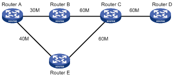
Figure 1 presents a scenario where a path Router A → Router B → Router C → Router D is established with 30 Mbps reserved bandwidth between Router A and Router D. The remaining bandwidth is then 30 Mbps.
If 40 Mbps path bandwidth is requested, the remaining bandwidth of the Router A → Router B → Router C → Router D path will be inadequate. The problem cannot be addressed by selecting another path, Router A → Router E → Router C → Router D, because the bandwidth of the Router C → Router D link is inadequate.
To address the problem, you may use the make-before-break mechanism. It allows the new path to share the bandwidth of the original path at the Router C → Router D link. Upon creation of the new path, traffic is switched to the new path and the previous path is torn down. This helps avoid traffic interruption effectively.
RSVP-TE messages
RSVP-TE uses RSVP messages with extensions. The following are RSVP messages:
· Path messages—Transmitted along the path of data transmission downstream by each RSVP sender to save path state information on each node along the path.
·Resv messages—Sent by each receiver upstream towards senders to request resource reservation and to create and maintain reservation state on each node along the reverse of data transmission path.
· PathTear messages—Sent downstream immediately once created to remove the path state and related reservation state on each node along the path.
· ResvTear messages—Sent upstream immediately once created to remove the reservation state on each node along the path.
· PathErr messages—Sent upstream to report Path message processing errors to senders. They do not affect the state of the nodes along the path.
· ResvErr messages—Sent downstream to notify the downstream nodes that error occurs during Resv message processing or reservation error occurs as the result of preemption.
· ResvConf messages—Sent to receivers to confirm Resv messages.
· Hello messages—Sent between any two directly connected RSVP neighbors to set up and maintain the neighbor relationship that has local significance on the link.
The TE extension to RSVP adds new objects to the Path message and the Resv message. These objects carry not only label bindings but also routing constraints, supporting CR-LSP and FRR.
· New objects added to the Path message include LABEL_REQUEST, EXPLICIT_ROUTE, RECORD_ROUTE, and SESSION_ATTRIBUTE.
· New objects added to the Resv message include LABEL and RECORD_ROUTE
The LABEL_REQUEST object in the Path message requests the label bindings for an LSP. It is also saved in the path state block. The node receiving LABEL_REQUEST advertises the label binding using the LABEL object in the Resv message to the upstream node, thus accomplishing label advertisement and transmission.
Setting up an LSP tunnel
Figure 2 shows how to set up a LSP tunnel with RSVP:
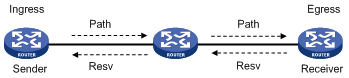
The following is a simplified procedure for setting up an LSP tunnel with RSVP:
1. The ingress LSR sends a Path message that carries the label request information, and then forwards the message along the path calculated by CSPF hop-by-hop towards the egress LSR.
2. After receiving the Path message, the egress generates a Resv message carrying the reservation information and label and then forwards the message towards the ingress along the reverse direction of the path along which the Path message travels. The LSRs that the Resv message traverses along the path reserve resources as required.
3. When the ingress LSR receives the Resv message, LSP is established.
As resources are reserved on the LSRs along the path for the LSP established using RSVP-TE, services transmitted on the LSP are guaranteed.
RSVP refresh mechanism
RSVP maintains path and reservation state by periodically retransmitting two types of messages: Path and Resv. These periodically retransmitted Path and Resv messages are called refresh messages. They are sent along the path that the last Path or Resv message travels to synchronize state between RSVP neighbors and recover lost RSVP messages.
When many RSVP sessions are present, periodically sent refresh messages become a network burden. In addition, for some delay sensitive applications, the refreshing delay they must wait for recovering lost RSVP messages may be unbearable. As tuning refresh intervals is not adequate to address the two problems, the refreshing mechanism was extended in RFC 2961 RSVP Refresh Overhead Reduction Extensions as follows to address the problems:
1. Message_ID extension
RSVP itself uses Raw IP to send messages. The Message_ID extension mechanism defined in RFC 2961 adds objects that can be carried in RSVP messages. Of them, the Message_ID object and the Message_ID_ACK object are used to acknowledge RSVP messages, thus improving transmission reliability.
On an interface enabled with the Message_ID mechanism, you may configure RSVP message retransmission. After the interface sends an RSVP message, it waits for acknowledgement. If no ACK is received before the initial retransmission interval (Rf seconds for example) expires, the interface resends the message. After that, the interface resends the message at an exponentially increased retransmission interval equivalent to (1 + Delta) × Rf seconds.
2. Summary refresh extension
Send summary refreshes (Srefreshes) rather than retransmit standard Path or Resv messages to refresh related RSVP state. This reduces refresh traffic and allows nodes to make faster processing.
To use summary refresh, you must use the Message_ID extension. Only states advertised using MESSAGE_ID included Path and Resv messages can be refreshed using summary refreshes.
PSB, RSB, and BSB timeouts
To create an LSP tunnel, the sender sends a Path message with a LABEL_REQUEST object. After receiving this Path message, the receiver assigns a label for the path and puts the label binding in the LABEL object in the returned Resv message.
The LABEL_REQUEST object is stored in the path state block (PSB) on the upstream nodes, while the LABEL object is stored in the reservation state block (RSB) on the downstream nodes. The state stored in the PSB or RSB object times out and is removed after the number of consecutive non-refreshing times exceeds the PSB or RSB timeout keep-multiplier.
You may sometimes want to store the resource reservation state for a reservation request that does not pass the admission control on some node. This however should not prevent the resources reserved for the request from being used by other requests. To handle this situation, the node transits to the blockade state and a blockade state block (BSB) is created on each downstream node. When the number of non-refreshing times exceeds the blockade multiplier, the state in the BSB is removed.
RSVP-TE GR
A device that participates in an RSVP-TE GR process plays either of the following two roles:
· GR restarter, the router that gracefully restarts due to a manually configured command or a fault. It must be GR-capable.
· GR helper, neighbor of the GR restarter. A GR helper maintains the neighbor relationship with the GR restarter and helps the GR restarter restore its LFIB information. A GR helper must be GR-capable.
The RSVP-TE GR function depends on the extended hello capability of RSVP-TE. A GR-capable device advertises its GR capability and relevant time parameters to its neighbors by extended RSVP hello packets. If a device and all its neighbors have the RSVP GR capability and have exchanged GR parameters, each of them can function as the GR helper of another device, allowing data to be forwarded without interruption when the GR restarter is rebooting.
A GR helper considers that a GR restarter is rebooting when it receives no Hello packets from the restarter in a specific period of time. When a GR restarter is rebooting, the GR helpers retain soft state information about the GR restarter and keep sending Hello packets periodically to the GR restarter until the restart timer expires.
If a GR helper and the GR restarter reestablish a Hello session before the restart timer expires, the recovery timer is started and signaling packet exchanging is triggered to restore the original soft state. Otherwise, all RSVP soft state information and forwarding entries relevant to the neighbor will be removed. If the recovery timer expires, soft state information and forwarding entries that are not restored during the GR restarting process will be removed.
|
|
NOTE: If configured with RSVP-TE GR, the router can act as a GR restarter and a GR helper at the same time. |
Traffic forwarding
Even when an MPLS TE tunnel is available, traffic is still IP routed if you do not configure it to travel the tunnel. For traffic to be routed along an MPLS TE tunnel, you can use static routing, policy-based routing, or automatic route advertisement.
Static routing
Static routing is the easiest way to route traffic along an MPLS TE tunnel. You only need to manually create a route that reaches the destination through the tunnel interface.
|
|
NOTE: For more information about static routing, see Layer 3—IP Routing Configuration Guide. |
Policy-based routing
You can also use policy-based routing to route traffic over an MPLS TE tunnel. In this approach, you need to create a policy that specifies the MPLS TE tunnel interface as the output interface for traffic that matches certain criteria defined in the referenced ACL.
This policy should be applied to the incoming interface.
|
|
NOTE: For more information about policy-based routing, see Layer 3—IP Routing Configuration Guide. |
Automatic route advertisement
You can use automatic route advertisement to advertise MPLS TE tunnel interface routes to IGPs, allowing traffic to be routed down MPLS TE tunnels.
Two approaches are available to automatic route advertisement: IGP shortcut and forwarding adjacency.
OSPF and IS-IS support both approaches where TE tunnels are considered point-to-point links and TE tunnel interfaces can be set as outgoing interfaces.
IGP shortcut, also known as autoroute announce, considers a TE tunnel as a logical interface directly connected to the destination when computing IGP routes on the ingress of the TE tunnel.
IGP shortcut and forwarding adjacency are different in that in the forwarding adjacency approach, routes with TE tunnel interfaces as outgoing interfaces are advertised to neighboring routers but not in the IGP shortcut approach. Therefore, TE tunnels are visible to other routers in the forwarding adjacency approach but not in the IGP shortcut approach.
Figure 3 IGP shortcut and forwarding adjacency
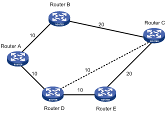
As shown in Figure 3, a TE tunnel is present between Router D and Router C. With IGP shortcut enabled, the ingress node Router D can use this tunnel when calculating IGP routes. This tunnel, however, is invisible to Router A; therefore, Router A cannot use this tunnel to reach Router C. With forwarding adjacency enabled, Router A can known the presence of the TE tunnel and thus forward traffic to Router C to Router D though this tunnel.
The configuration of IGP shortcut and forwarding adjacency is broken down into tunnel configuration and IGP configuration. When making tunnel configuration on a TE tunnel interface, consider the following:
· The tunnel destination address should be in the same area where the tunnel interface is located.
· The tunnel destination address should be reachable through intra-area routing.
CR-LSP backup
CR-LSP backup provides end-to-end path protection for the entire LSP without time limitation. This is different from Fast Reroute (FRR) which provides quick but temporary per-link or per-node protection on an LSP.
In the same TE tunnel, the LSP used to back up a primary LSP is called a secondary LSP. When the ingress of a TE tunnel detects that the primary LSP is unavailable, it switches traffic to the secondary LSP and after the primary LSP becomes available, switches traffic back. This is how LSP path protection is achieved.
Two approaches are available for CR-LSP backup:
· Hot backup where a secondary CR-LSP is created immediately after a primary CR-LSP is created. MPLS TE switches traffic to the secondary CR-LSP after the primary CR-LSP fails.
· Standard backup where a secondary CR-LSP is created to take over after the primary CR-LSP fails.
FRR
Overview
Fast Reroute (FRR) provides a quick per-link or per-node protection on an LSP.
In this approach, once a link or node fails on a path, FRR comes up to reroute the path to a new link or node to bypass the failed link or node. This can happen as fast as 50 milliseconds thus minimizing data loss.
Once a link or node on an LSP configured with FRR fails, traffic is switched to the protection link and the headend of the LSP starts attempting to set up a new LSP.
Basic concepts
The following are concepts that FRR involves throughout this document:
· Primary LSP—The protected LSP.
· Bypass LSP—An LSP used to protect the primary LSP.
· Point of local repair (PLR)—The ingress of the bypass LSP. It must be located on the primary LSP but must not be the egress.
· Merge point (MP)—The egress of the bypass LSP. It must be located on the primary LSP but must not be the ingress.
Protection
FRR provides link protection and node protection for an LSP as follows:
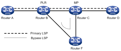
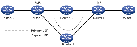
· Link protection, where the PLR and the MP are connected through a direct link and the primary LSP traverses this link. When the link fails, traffic is switched to the bypass LSP. As shown in Figure 4, the primary LSP is Router A → Router B → Router C → Router D, and the bypass LSP is Router B → Router F → Router C.
Figure 4 FRR link protection
· Node protection, where the PLR and the MP are connected through a router and the primary LSP traverses this router. When the router fails, traffic is switched to the bypass LSP. As shown in Figure 5, the primary LSP is Router A → Router B → Router C → Router D → Router E, and the bypass LSP is Router B → Router F→ Router D. Router C is the protected router.
Figure 5 FRR node protection
Deploying FRR
When configuring the bypass LSP, make sure the protected link or node is not on the bypass LSP.
Because bypass LSPs are pre-established, FRR requires extra bandwidth. When network bandwidth is insufficient, use FRR for crucial interfaces or links only.
PS for an MPLS TE tunnel
Protection switching (PS) refers to establishing one or more protection tunnels (backup tunnels) for a main tunnel. A main tunnel and its protection tunnels form a protection group. When the main tunnel fails, data is switched to a protection tunnel immediately, greatly improving the reliability of the network. When the main tunnel recovers, data can be switched back to the main tunnel.
At present, the router supports only 1:1 protection switching, that is, one protection tunnel is used to service one main tunnel. Between the ingress and egress, there are two tunnels, one main and one backup. Normally, user data travels along the main tunnel. If the ingress finds a defect of the main tunnel by using a probing mechanism, it will switch data to the protection tunnel.
Protection switching may be command triggered or signal triggered.
1. Command switching refers to a PS triggered by an externally configured switching command, which can define the following switching actions (in the descending order of priority):
¡ clear—Clears all configured switching actions.
¡ lock (lockout of protection)—Always uses the main LSP to transfer data.
¡ force (forced switch)—Forces data to travel on the backup LSP.
¡ manual (manual switch)—Switches data from the main LSP to the backup LSP or vice versa.
2. Signal switching (Signal Fail) refers to a PS automatically triggered by a signal fail declaration. Examples include a PS that occurs during BFD detection for MPLS-TE tunnels.
In practice, a switching command takes effect only when its priority is higher than that of a signal fail declaration.
The following shows the priority of the externally configured switching actions and the signal fail switching, in the descending order:
¡ Clear
¡ Lockout of protection
¡ Forced switch
¡ Signal fail
¡ Manual switch
DiffServ-aware TE
Overview
Diff-Serv is a model that provides differentiated QoS guarantees based on class of service.
MPLS TE is a traffic engineering solution that focuses on optimizing network resources allocation.
DiffServ-aware TE (DS-TE) combines them to optimize network resources allocation at a per-service class level. For traffic trunks which are distinguished by class of service, this means varied bandwidth constraints. Essentially, what DS-TE does is to map traffic trunks with LSPs, making each traffic trunk traverse the constraints-compliant path.
The router supports the following DS-TE modes:
· Prestandard mode—Implemented by using H3C proprietary mechanisms
· IETF mode—Implemented according to RFC 4124, RFC 4125, and RFC 4127.
Basic concepts
· Class Type (CT): A set of traffic trunks crossing a link that is governed by a specific set of bandwidth constraints. DS-TE allocates link bandwidth, implements constraint-based routing, and performs admission control for a traffic trunk according to the traffic trunk’s CT. A given traffic trunk belongs to the same CT on all links.
· Bandwidth Constraint (BC): Restricts the bandwidth for one or more class types.
· Bandwidth constraints model: Algorithm for implementing bandwidth constraints on different CTs. A BC model comprises two factors, the maximum number of Bandwidth Constraints (MaxBC) and the mappings between BCs and CTs. DS-TE supports two BC models, Russian Dolls Model (RDM) and Maximum Allocation Model (MAM).
· TE class: A pair consisting of a CT and a preemption priority for the CT. The setup priority or holding priority of an LSP transporting a traffic trunk from that CT must be the preemption priority for the CT.
|
|
NOTE: · The prestandard mode supports two CTs (CT 0 and CT 1), eight priorities, and up to 16 TE classes. The IETF mode supports four CTs (CT 0 through CT 3), eight priorities, and up to eight TE classes. · The prestandard mode is proprietary, and therefore a device working in prestandard mode cannot communicate with devices of some other vendors. The IETF mode is a standard mode implemented according to relative RFCs. A device working in IETF mode can communicate with devices of other vendors. |
Working process
To establish MPLS TE tunnels according to CTs of traffic trunks, a router needs to:
1. Determine the CT of traffic flows.
A router classifies traffic flows according to your configuration.
¡ When configuring a dynamic MPLS TE tunnel, you can use the mpls te bandwidth command on the tunnel interface to specify a CT for the traffic flows to be forwarded by the tunnel.
¡ When configuring a static MPLS TE tunnel, you can use the bandwidth keyword to specify a CT for the traffic flows to be forwarded along the tunnel.
2. Check whether there is enough bandwidth available for the CT.
You can use the mpls te max-reservable-bandwidth command on an MPLS TE tunnel interface to configure the bandwidth constraints of the tunnel interface. The router determines whether there is enough bandwidth to establish an MPLS TE tunnel for a traffic trunk according to the traffic trunk’s CT and the tunnel interface’s BCs.
The relation between BCs and CTs varies in different BC models:
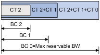
In RDM model, a BC constrains the total bandwidth of multiple CTs, as shown in Figure 6:
¡ BC 2 is for CT 2. The total bandwidth of the traffic of CT 2 cannot exceed BC 2.
¡ BC 1 is for CT 2 and CT 1. The total bandwidth of the traffic of CT 2 and CT 1 cannot exceed BC 1.
¡ BC 0 is for CT 2, CT 1, and CT 0. The total bandwidth of the traffic of CT 2, CT 1, and CT 0 cannot exceed BC 0. In this model, BC 0 equals the maximum reservable bandwidth of the tunnel.
In cooperation with priority preemption, the RDM model can also implement the isolation across CTs, ensuring each CT its share of bandwidth. RDM is suitable for networks where traffic is unstable and traffic bursts may occur.
Figure 6 RDM bandwidth constraints model
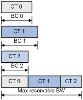
In MAM model, a BC constrains the bandwidth of only one CT on an interface. This ensures isolation across CTs no matter whether preemption is used or not. Compared with RDM, MAM is easy to understand and configure. MAM is suitable for networks where traffic of each CT is stable. Figure 7 shows an example:
¡ BC 0 is for CT 0. The bandwidth occupied by the traffic of CT 0 cannot exceed BC 0.
¡ BC 1 is for CT 1. The bandwidth occupied by the traffic of CT 1 cannot exceed BC 1.
¡ BC 2 is for CT 2. The bandwidth occupied by the traffic of CT 2 cannot exceed BC 2.
¡ The total bandwidth occupied by CT 0, CT 1, and CT 2 cannot exceed the maximum reservable bandwidth.
Figure 7 MAM bandwidth constraints model
3. Check whether the traffic trunk matches an existing TE class.
The router checks whether the CT and the LSP setup/holding priority of the traffic trunk matches an existing TE class. An MPLS TE tunnel can be established for the traffic trunk only when the following conditions are satisfied:
¡ Every node along the tunnel has a TE class that matches the traffic trunk’s CT and the LSP setup priority.
¡ Every node along the tunnel has a TE class that matches the traffic trunk’s CT and the LSP holding priority.
|
|
NOTE: The prestandard mode does not allow you to configure TE classes, while the IETF mode allows for TE class configuration. |
MPLS LDP over MPLS TE
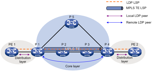
Figure 8 Establish an LDP LSP across the network core layer
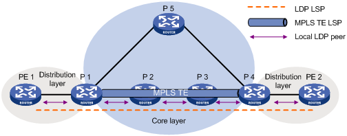
As the figure shows, in layered networks, MPLS TE is usually deployed only in the core layer, and MPLS networks in the distribution layer usually use LDP as the label distribution signaling. To set up an LDP LSP tunnel across the core layer, you need to establish a local LDP session between each pair of neighboring LSRs in the core layer.
To simplify the configuration, when setting up an LDP LSP across the core layer, you can use the MPLS TE tunnel that is already established in the core layer. As shown in Figure 9, when using the MPLS TE tunnel to establish the LDP LSP, you do not need to establish local LDP sessions between neighboring LSRs in the core layer. All you have to do is to establish a remote session between the headend and tailend of the MPLS TE tunnel. Then, label bindings can be exchanged and an LDP LSP can be established between the MPLS TE tunnel headend and tailend. The LDP LSP is carried on the MPLS TE tunnel. In this way, a hierarchical LSP is formed.
Figure 9 Configure an LDP LSP over an MPLS TE LSP
|
|
NOTE: By default, LDP does not advertise any prefix-based label mapping message through a remote session. To enable LDP to advertise prefix-based labels through a remote session, you need to configure the prefix-label advertise command. For more information about the prefix-label advertise command, see MPLS Command Reference. |
Protocols and standards
· RFC 2702, Requirements for Traffic Engineering Over MPLS
· RFC 3212, Constraint-Based LSP Setup using LDP
· RFC 2205, Resource ReSerVation Protocol
· RFC 3209, RSVP-TE: Extensions to RSVP for LSP Tunnels
· RFC 2961, RSVP Refresh Overhead Reduction Extensions
· RFC 3564, Requirements for Support of Differentiated Service-aware MPLS Traffic Engineering
· ITU-T Recommendation Y.1720, Protection switching for MPLS networks
MPLS TE configuration task list
Complete the following tasks to configure MPLS TE:
|
Task |
Remarks |
||
|
Required |
|||
|
Optional |
|||
|
Configuring an MPLS TE tunnel |
Required Use either approach |
||
|
Optional |
|||
|
Optional |
|||
|
Optional |
|||
|
Forwarding traffic along MPLS TE tunnels using static routes |
Required Use either approach |
||
|
Forwarding traffic along MPLS TE tunnels through automatic route advertisement |
|||
|
Optional |
|||
|
Optional |
|||
|
Optional |
|||
|
Optional |
|||
|
Optional |
|||
Configuring MPLS TE basic capabilities
MPLS TE basic capabilities are essential to MPLS TE feature configurations. After configuring the basic capabilities, you need to make other configurations in order to use MPLS TE depending on the actual requirements.
Configuration prerequisites
Before the configuration, do the following:
· Configure static routing or IGPs to make sure all LSRs are reachable.
· Configure MPLS basic capabilities.
|
|
NOTE: For configuration information about MPLS basic capability, see MPLS Configuration Guide. |
Configuration procedure
To configure MPLS TE basic capabilities:
|
Step |
Command |
Remarks |
|
1. Enter system view. |
system-view |
N/A |
|
2. Enter MPLS view. |
mpls |
N/A |
|
3. Enable global MPLS TE. |
mpls te |
Disabled by default |
|
4. Return to system view. |
quit |
N/A |
|
5. Enter the interface view of an MPLS TE link. |
interface interface-type interface-number |
N/A |
|
6. Enable interface MPLS TE. |
mpls te |
Disabled by default |
|
7. Return to system view. |
quit |
–– |
|
8. Create a tunnel interface and enter its view. |
interface tunnel tunnel-number |
N/A |
|
9. Assign an IP address to the tunnel interface. |
ip address ip-address netmask |
Optional |
|
10. Set the tunnel protocol to MPLS TE. |
tunnel-protocol mpls te |
N/A |
|
11. Configure the destination address of the tunnel. |
destination ip-address |
N/A |
|
12. Configure the tunnel ID of the tunnel. |
mpls te tunnel-id tunnel-id |
N/A |
|
13. Submit the current tunnel configuration. |
mpls te commit |
N/A |
|
|
NOTE: For more information about tunnel interfaces, see Layer 3—IP Services Configuration Guide. |
Configuring DiffServ-aware TE
To configure DS-TE:
|
Step |
Command |
Remarks |
|
1. Enter system view. |
system-view |
N/A |
|
2. Enter MPLS view. |
mpls |
N/A |
|
3. Configure the DS-TE mode as IETF. |
mpls te ds-te mode ietf |
Optional. By default, the DS-TE mode is prestandard. |
|
4. Configure the BC model of IETF DS-TE as MAM. |
mpls te ds-te ietf bc-mode mam |
Optional. By default, the BC model of IETF DS-TE is RDM. |
|
5. Configure the TE class mapping in IETF DS-TE mode, that is, the TE class-CT-priority association. |
mpls te ds-te ietf te-class te-class-index class-type class-type-number priority pri-number |
Optional. By default, the TE class mappings in IETF mode are shown as Table 1. |
Table 1 Default TE class mappings in IETF mode
|
TE Class |
CT |
Priority |
|
0 |
0 |
7 |
|
1 |
1 |
7 |
|
2 |
2 |
7 |
|
3 |
3 |
7 |
|
4 |
0 |
0 |
|
5 |
1 |
0 |
|
6 |
2 |
0 |
|
7 |
3 |
0 |
Creating MPLS TE tunnel over static CR-LSP
Creating MPLS TE tunnels over static CR-LSPs does not involve configuration of tunnel constraints or the issue of IGP TE extension or CSPF. What you need to do is to create a static CR-LSP and a TE tunnel using static signaling and then associate them.
Despite its ease of configuration, the application of MPLS TE tunnels over static CR-LSPs is restricted because they cannot dynamically adapt to network changes.
Static CR-LSPs are special static LSPs. They share the same constraints and use the same label space.
Configuration prerequisites
Before making the configuration, do the following:
· Configure static routing or an IGP protocol to make sure that all LSRs are reachable.
· Configure MPLS basic capabilities.
· Configure MPLS TE basic capabilities.
Configuration procedure
To create an MPLS TE tunnel over a CR-LSP:
|
Step |
Command |
Remarks |
|
1. Enter system view. |
system-view |
N/A |
|
2. Enter the interface view of an MPLS TE tunnel. |
interface tunnel tunnel-number |
N/A |
|
3. Configure the tunnel to use static CR-LSP. |
mpls te signal-protocol static |
N/A |
|
4. Submit the current tunnel configuration. |
mpls te commit |
N/A |
|
5. Exit to system view. |
quit |
N/A |
|
6. Create a static CR-LSP on your router depending on its location in the network. |
·
At the ingress: ·
On the transit node: ·
At the egress: |
Use any of the commands depending on the location of your router in the network. |
Configuring MPLS TE tunnel with dynamic signaling protocol
Dynamic signaling protocol can adapt the path of a TE tunnel to network changes and implement redundancy, FRR, and other advanced features.
The following describes how to create an MPLS TE tunnel with a dynamic signaling protocol:
· Configure MPLS TE properties for links and advertise them through IGP TE extension to form a TEDB.
· Configure tunnel constraints.
· Use the CSPF algorithm to calculate a preferred path based on the TEDB and tunnel constraints.
· Establish the path by using the signaling protocol RSVP-TE or CR-LDP.
|
|
NOTE: To form a TEDB, you must configure the IGP TE extension for the nodes on the network to send TE LSAs. If the IGP TE extension is not configured, the CR-LSP is created based on IGP routing rather than computed by CSPF. |
Configuration prerequisites
Before making the configuration, do the following:
· Configure static routing or an IGP protocol to make sure that all LSRs are reachable.
· Configure MPLS basic capabilities.
· Configure MPLS TE basic capabilities.
Configuration procedure
Complete the following tasks to configure an MPLS TE tunnel using a dynamic signaling protocol:
|
Task |
Remarks |
|
Optional. |
|
|
Optional. |
|
|
Required when CSPF is configured. Choose one depending on the IGP protocol used. |
|
|
Optional. |
|
|
Optional. |
|
|
Optional. Use either approach. By default, RSVP-TE is used for establishing an MPLS TE tunnel. |
|
Configuring MPLS TE properties for a link
To configure MPLS TE properties for a link:
|
Step |
Command |
Remarks |
|
1. Enter system view. |
system-view |
N/A |
|
2. Enter interface view of MPLS TE link. |
interface interface-type interface-number |
N/A |
|
3. Configure maximum link bandwidth. |
mpls te max-link-bandwidth bandwidth-value |
Optional. 0 by default. |
|
4. Configure BC 0 and BC 1 of the MPLS TE link in the RDM model of the prestandard DS-TE. |
mpls te max-reservable-bandwidth bandwidth-value [ bc1 bc1-bandwidth ] |
Optional. 0 for both BC 0 and BC 1 by default. In RDM model, BC 0 is the maximum reservable bandwidth of a link. |
|
5. Configure maximum reservable bandwidth and BCs of the MPLS TE link in the MAM model of the IETF DS-TE. |
mpls te max-reservable-bandwidth mam bandwidth-value { bc0 bc0-bandwidth | bc1 bc1-bandwidth | bc2 bc2-bandwidth | bc3 bc3-bandwidth } * |
Optional. By default, the maximum bandwidth, and BC 0 through BC 3 are all 0. |
|
6. Configure the BCs of the MPLS TE link in the RDM model of the IETF DS-TE. |
mpls te max-reservable-bandwidth rdm bandwidth-value [ bc1 bc1-bandwidth ] [ bc2 bc2-bandwidth ] [ bc3 bc3-bandwidth ] |
Optional. 0 for BC 0 through BC 3 by default In RDM model, BC 0 is the maximum reservable bandwidth of a link. |
Configuring CSPF
To configure CSPF:
|
Step |
Command |
Remarks |
|
1. Enter system view. |
system-view |
N/A |
|
2. Enter MPLS view. |
mpls |
N/A |
|
3. Enable CSPF on your router. |
mpls te cspf |
Disabled by default |
Configuring OSPF TE
Configure OSPF TE if the routing protocol is OSPF and a dynamic signaling protocol is used for MPLS TE tunnel setup.
The OSPF TE extension uses Opaque Type 10 LSAs to carry TE attributes of links. Before configuring OSPF TE, you need to enable the opaque capability of OSPF. In addition, for TE LSAs to be generated, at least one neighbor must be in full state.
To configure OSPF TE:
|
Step |
Command |
Remarks |
|
1. Enter system view. |
system-view |
N/A |
|
2. Enter OSPF view. |
ospf [ process-id ] |
N/A |
|
3. Enable the opaque LSA capability. |
opaque-capability enable |
Disabled by default |
|
4. Enter OSPF area view. |
area area-id |
N/A |
|
5. Enable MPLS TE in the OSPF area. |
mpls-te enable |
Disabled by default |
|
6. Return to OSPF view. |
quit |
N/A |
|
|
NOTE: · For more information about OSPF opaque LSA, see Layer 3—IP Routing Configuration Guide. · MPLS TE cannot reserve resources and distribute labels on OSPF virtual links. MPLS TE cannot establish an LSP tunnel through an OSPF virtual link. Make sure no virtual links exist in the OSPF routing domain when configuring OSPF TE. |
Configuring IS-IS TE
Configure IS-IS TE if the routing protocol is IS-IS and a dynamic signaling protocol is used for MPLS TE tunnel setup. In case both OSPF TE and IS-IS TE are available, OSPF TE takes priority.
The IS-IS TE extension uses the sub-TLV of IS reachability TLV (type 22) to carry TE attributes. Before configuring IS-IS TE, you need to configure the IS-IS wide metric style, which can be wide, compatible, or wide-compatible.
|
|
CAUTION: · According to RFC 3784, the length of the IS reachability TLV (type 22) may reach the maximum of 255 octets in some cases. · For an IS-IS LSP to carry this type of TLV and to be flooded normally on all interfaces with IS-IS enabled, the MTU of any IS-IS enabled interface, including 27 octets of LSP header and two octets of TLV header, cannot be less than 284 octets. If an LSP must also carry the authentication information, the minimum MTU needs to be recalculated according to the packet structure. When TE is configured, H3C recommends that you set the MTU of any interface with IS-IS enabled be equal to or greater than 512 octets to guarantee that IS-IS LSPs can be flooded on the network. |
To configure IS-IS TE:
|
Step |
Command |
Remarks |
|
1. Enter system view. |
system-view |
–– |
|
2. Enter IS-IS view. |
isis [ process-id ] |
–– |
|
3. Configure the wide metric attribute of IS-IS. |
cost-style { narrow | wide | wide-compatible | { compatible | narrow-compatible } [ relax-spf-limit ] } |
By default, IS-IS uses narrow metric style. |
|
4. Enable IS-IS TE. |
traffic-eng [ level-1 | level-2 | level-1-2 ] |
Disabled by default. |
|
5. Configure the TLV type of the sub-TLV carrying DS-TE parameters. |
te-set-subtlv { bw-constraint value | lo-multiplier value | unreserved-bw-sub-pool value } |
Optional. By default, the bw-constraint parameter is carried in sub-TLV 252; the lo-multiplier parameter in sub-TLV 253; and the unreserved-bw-sub-pool parameter in sub-TLV 251. |
|
|
NOTE: · For more information about IS-IS, see Layer 3—IP Routing Configuration Guide. · IS-IS TE does not support secondary IP address advertisement. With IS-IS TE enabled on an interface configured with multiple IP addresses, IS-IS TE advertises only the primary IP address of the interface through the sub-TLV of IS reachability TLV (type 22). H3C does not recommend enabling IS-IS TE on an interface configured with secondary IP addresses. |
Configuring an MPLS TE explicit path
An explicit path is a set of nodes. The relationship between any two neighboring nodes on an explicit path can be either of the following:
· Strict: where the two nodes are directly connected.
· Loose: where the two nodes have routers in between.
When inserting nodes to an explicit path or modifying nodes on it, you may configure the include keyword to have the established LSP traverse the specified nodes or the exclude keyword to have the established LSP bypass the specified nodes.
To configure an MPLS TE explicit path:
|
Step |
Command |
Remarks |
|
1. Enter system view. |
system-view |
N/A |
|
2. Create an explicit path for MPLS TE tunneling and enter its view. |
explicit-path path-name [ disable | enable ] |
N/A |
|
3. Add a node to the explicit path. |
add hop ip-address1 [ include [ loose | strict ] | exclude ] { after | before } ip-address2 |
Optional. By default, the include keyword and the strict keyword apply. In other words, the explicit path traverses the specified node and the next node is a strict node. |
|
4. Specify a next hop IP address on the explicit path. |
next hop ip-address [ include [ loose | strict ] | exclude ] |
The next hop is a strict node by default. Repeat this step to define a sequential set of the hops that the explicit path traverses. |
|
5. Modify the IP address of current node on the explicit path. |
modify hop ip-address1 ip-address2 [ [ include [ loose | strict ] | exclude ] |
Optional. By default, the include keyword and the strict keyword apply. In other words, the explicit path traverses the specified node and the next node is a strict node. |
|
6. Remove a node from the explicit path. |
delete hop ip-address |
Optional. |
|
7. Display information about the specified or all nodes on the explicit path. |
list hop [ ip-address ] |
Optional. |
Configuring MPLS TE tunnel constraints
To configure MPLS TE tunnel constraints:
|
Step |
Command |
Remarks |
|
1. Enter system view. |
system-view |
N/A |
|
2. Enter MPLS TE tunnel interface view. |
interface tunnel tunnel-number |
N/A |
|
3. Assign bandwidth to the MPLS TE tunnel, and specify a CT for the tunnel’s traffic. |
mpls te bandwidth [ ct0 | ct1 | ct2 | ct3 ] bandwidth |
Optional. By default, no bandwidth is assigned and traffic of the tunnel belongs to CT 0. |
|
4. Specify a path for the tunnel to use and set the preference of the path. |
mpls te path { dynamic | explicit-path pathname } preference value |
Optional. By default, a tunnel uses the dynamically calculated path. |
|
5. Submit current tunnel configuration. |
mpls te commit |
N/A |
Establishing an MPLS TE tunnel with CR-LDP
To establish an MPLS TE tunnel with CR-LDP:
|
Step |
Command |
Remarks |
|
1. Enter system view. |
system-view |
N/A |
|
2. Enter MPLS TE tunnel interface view. |
interface tunnel tunnel-number |
N/A |
|
3. Set the signaling protocol for setting up MPLS TE tunnels to CR-LDP. |
mpls te signal-protocol crldp |
RSVP-TE applies by default. |
|
4. Submit current tunnel configuration. |
mpls te commit |
N/A |
|
|
NOTE: When establishing an MPLS TE tunnel with CR-LDP, you cannot use the mpls te bandwidth command to configure bandwidth for the tunnel. |
Establishing an MPLS TE tunnel with RSVP-TE
To establish an MPLS TE tunnel with RSVP-TE:
|
Step |
Command |
Remarks |
|
1. Enter system view. |
system-view |
N/A |
|
2. Enter MPLS view. |
mpls |
N/A |
|
3. Enable RSVP-TE on your router. |
mpls rsvp-te |
Disabled by default. |
|
4. Exit to system view. |
quit |
N/A |
|
5. Enter interface view of MPLS TE link. |
interface interface-type interface-number |
N/A |
|
6. Enable RSVP-TE on the interface. |
mpls rsvp-te |
Disabled by default. |
|
7. Enter MPLS TE tunnel interface view. |
interface tunnel tunnel-number |
N/A |
|
8. Set the signaling protocol for setting up the MPLS TE tunnel to RSVP-TE. |
mpls te signal-protocol rsvp-te |
Optional. RSVP-TE applies by default. |
|
9. Submit current tunnel configuration. |
mpls te commit |
N/A |
|
|
CAUTION: To use RSVP-TE as the signaling protocol for setting up the MPLS TE tunnel, you must enable both MPLS TE and RSVP-TE on the interfaces for the tunnel to use. |
Configuring RSVP-TE advanced features
RSVP-TE adds new objects in Path and Resv messages to support CR-LSP setup. RSVP-TE provides many configurable options with respect to reliability, network resources, and other advanced features of MPLS TE.
Before performing the configuration tasks in this section, be aware of each configuration objective and its impact on your network.
Configuration prerequisites
Before configuring RSVP-TE advanced features, do the following:
· Configure MPLS basic capabilities
· Configure MPLS TE basic capabilities
· Establish an MPLS TE tunnel with RSVP-TE
Configuration procedure
Configuring RSVP reservation style
Each LSP set up using RSVP-TE is assigned a resource reservation style. During an RSVP session, the receiver decides which reservation style can be used for this session and thus which LSPs can be used.
Currently, two reservation styles are available:
· Fixed-filter style (FF) where resources are reserved for individual senders and cannot be shared among senders on the same session.
· Shared-explicit style (SE) where resources are reserved for senders on the same session and shared among them.
To configure RSVP reservation style:
|
Step |
Command |
Remarks |
|
1. Enter system view. |
system-view |
N/A |
|
2. Enter MPLS TE tunnel interface view. |
interface tunnel tunnel-number |
N/A |
|
3. Configure the resources reservation style for the tunnel. |
mpls te resv-style { ff | se } |
Optional. The default resource reservation style is SE. |
|
4. Submit current tunnel configuration. |
mpls te commit |
N/A |
|
|
NOTE: In current MPLS TE applications, the SE style is mainly used for make-before-break, while the FF style is rarely used. |
Configuring RSVP state timers
To configure RSVP state timers:
|
Step |
Command |
Remarks |
|
1. Enter system view. |
system-view |
N/A |
|
2. Enter MPLS view. |
mpls |
N/A |
|
3. Configure the path/reservation state refresh interval of the node. |
mpls rsvp-te timer refresh timevalue |
Optional. The default path/reservation state refresh interval is 30 seconds. |
|
4. Configure the keep multiplier for PSB and RSB. |
mpls rsvp-te keep-multiplier number |
Optional. The default is 3. |
|
5. Configure the blockade timeout multiplier. |
mpls rsvp-te blockade-multiplier number |
Optional. The default blockade timeout multiplier is 4. |
Configuring the RSVP refreshing mechanism
To enhance reliability of RSVP message transmission, the Message_ID extension mechanism is used to acknowledge RSVP messages. The Message_ID extension mechanism is also referred to as the reliability mechanism throughout this document.
After you enable RSVP message acknowledgement on an interface, you may enable retransmission.
To use summary refresh (Srefresh), you must use the Message_ID extension. Only states advertised using MESSAGE_ID included Path and Resv messages can be refreshed using summary refreshes.
To configure RSVP refreshing mechanism:
|
Step |
Command |
Remarks |
|
1. Enter system view. |
system-view |
N/A |
|
2. Enter interface view of MPLS TE link. |
interface interface-type interface-number |
N/A |
|
3. Enable the reliability mechanism of RSVP-TE. |
mpls rsvp-te reliability |
Optional |
|
4. Enable retransmission. |
mpls rsvp-te timer retransmission { increment-value [ increment-value ] | retransmit-value [ retrans-timer-value ] } * |
Optional Disabled by default |
|
5. Enable summary refresh. |
mpls rsvp-te srefresh |
Optional Disabled by default |
Configuring the RSVP hello extension
To configure the RSVP hello extension:
|
Step |
Command |
Remarks |
|
1. Enter system view. |
system-view |
N/A |
|
2. Enter MPLS view. |
mpls |
N/A |
|
3. Enable global RSVP hello extension. |
mpls rsvp-te hello |
Disabled by default. |
|
4. Configure the maximum number of consecutive hellos that should be lost before the link is considered failed.. |
mpls rsvp-te hello-lost times |
Optional. By default, the link is considered failed if three consecutive hellos are lost. |
|
5. Configure the hello interval. |
mpls rsvp-te timer hello timevalue |
Optional. The default is 3 seconds. |
|
6. Exit to system view. |
quit |
N/A |
|
7. Enter interface view of MPLS TE link. |
interface interface-type interface-number |
N/A |
|
8. Enable interface RSVP hello extension. |
mpls rsvp-te hello |
Disabled by default. |
|
|
NOTE: RSVP hello extension detects the reachability of RSVP neighboring nodes. It is defined in RFC 3209. |
Configuring RSVP-TE resource reservation confirmation
To configure RSVP-TE resource reservation confirmation:
|
Step |
Command |
Remarks |
|
1. Enter system view. |
system-view |
N/A |
|
2. Enter MPLS view. |
mpls |
N/A |
|
3. Enable resource reservation confirmation. |
mpls rsvp-te resvconfirm |
Disabled by default |
|
|
NOTE: · Reservation confirmation is initiated by the receiver, which sends the Resv message with an object requesting reservation confirmation. · Receiving the ResvConf message does not mean resource reservation is established. It only indicates that resources are reserved on the farthest upstream node where the Resv message arrived and the resources can be preempted. |
Configuring RSVP authentication
RSVP adopts hop-by-hop authentication to prevent fake resource reservation requests from occupying network resources.
It requires that the interfaces at the two ends of a link must share the same authentication key to exchange RSVP messages.
To configure RSVP authentication:
|
Step |
Command |
|
1. Enter system view. |
system-view |
|
2. Enter interface view of MPLS TE link. |
interface interface-type interface-number |
|
3. Enable RSVP authentication. |
mpls rsvp-te authentication { cipher | plain } auth-key |
|
|
NOTE: FRR and RSVP authentication cannot run at the same time. |
Configuring RSVP-TE GR
The RSVP-TE GR function depends on the extended hello capability of RSVP-TE. Be sure to enable the extended hello capability of RSVP-TE before configuring RSVP-TE GR.
To configure RSVP-TE GR on each router to act as the GR restarter or a GR helper:
|
Step |
Command |
Remarks |
|
1. Enter system view. |
system-view |
N/A |
|
2. Enter MPLS view. |
mpls |
N/A |
|
3. Enable global RSVP hello extension. |
mpls rsvp-te hello |
Disabled by default |
|
4. Enable MPLS RSVP-TE GR. |
mpls rsvp-te graceful-restart |
Disabled by default |
|
5. Set the RSVP-TE GR restart timer. |
mpls rsvp-te timer graceful-restart restart restart-time |
Optional 120 seconds by default |
|
6. Set the RSVP-TE GR recovery timer. |
mpls rsvp-te timer graceful-restart recovery recovery-time |
Optional 300 seconds by default |
|
7. Enter interface view of MPLS TE link. |
interface interface-type interface-number |
N/A |
|
8. Enable RSVP hello extension for the interface. |
mpls rsvp-te hello |
Disabled by default |
Configuring Cooperation of RSVP-TE and BFD
To configure BFD for an RSVP-TE-enabled interface:
|
Step |
Command |
Remarks |
|
1. Enter system view. |
system-view |
N/A |
|
2. Enter the view of an MPLS RSVP-TE enabled interface. |
interface interface-type tunnel-number |
N/A |
|
3. Enable BFD on the RSVP-TE enabled interface. |
mpls rsvp-te bfd enable |
Disabled by default |
Tuning CR-LSP setup
A CR-LSP is established through the signaling protocol based on the path calculated by CSPF using TEDB and constraints. MPLS TE can affect CSPF calculation in many ways to determine the path that a CR-LSP can traverse.
Configuration prerequisites
The configuration tasks described in this section are about CSPF of MPLS TE. They must be used in conjunction with CSPF and the dynamic signal protocol (CR-LDP or RSVP-TE). Before performing them, be aware of each configuration objective and its impact on your system.
Configuration procedure
Configuring the tie breaker in CSPF
CSPF only calculates the shortest path to the end of a tunnel. If multiple paths are present with the same metric, only one of them is selected. Tie-breaking methods, in the descending order of selection priority, include: selecting a path with the lowest bandwidth usage ratio (the used bandwidth to the maximum reservable link bandwidth), selecting a path with the highest bandwidth usage ratio (the used bandwidth to the maximum reserved link bandwidth), and selecting a path randomly.
To configure the CSPF tie-breaking method:
|
Step |
Command |
Remarks |
|
1. Enter system view. |
system-view |
N/A |
|
2. Enter MPLS view. |
mpls |
N/A |
|
3. Specify the tie breaker that a tunnel uses to select a path when multiple paths with the same metric are present on the current node. |
mpls te tie-breaking { least-fill | most-fill | random } |
Optional. The random keyword applies by default. |
|
4. Enter MPLS TE tunnel interface view. |
interface tunnel tunnel-number |
N/A |
|
5. Specify the tie breaker for the current tunnel to select a path when multiple paths with the same metric are present. |
mpls te tie-breaking { least-fill | most-fill | random } |
Optional. By default, a tunnel has no specific tie breaker specified and uses the tie breaker specified in MPLS view. |
|
6. Submit current tunnel configuration. |
mpls te commit |
N/A |
|
|
NOTE: · A tunnel prefers the tie breaker specified in the tunnel interface view. If no tie breaker is specified in tunnel interface view, the tunnel uses the tie breaker specified in MPLS view to select a path. · The IETF DS-TE mode supports only random path selection. |
Configuring route pinning
Route pinning cannot be used together with reoptimization or automatic bandwidth adjustment.
To configure route pinning:
|
Step |
Command |
Remarks |
|
1. Enter system view. |
system-view |
N/A |
|
2. Enter MPLS TE tunnel interface view. |
interface tunnel tunnel-number |
N/A |
|
3. Enable route pinning. |
mpls te route-pinning |
Disabled by default |
|
4. Submit current tunnel configuration. |
mpls te commit |
N/A |
Configuring administrative group and affinity attribute
The affinity attribute of an MPLS TE tunnel identifies the properties of the links that the tunnel can use. Together with the link administrative group, it decides which links the MPLS TE tunnel can use. This is done by ANDing the 32-bit affinity attribute with the 32-bit link administrative group attribute. When doing that, a 32-bit mask is used. The affinity bits corresponding to the 1s in the mask are “do care” bits which must be considered while those corresponding to the 0s in the mask are “don’t care” bits.
For a link to be used by a TE tunnel, at least one considered affinity bit and its corresponding administrative group bit must be set to 1.
Suppose the affinity of an MPLS TE tunnel is 0xFFFFFFFF and the mask is 0x0000FFFF. For a link to be used by the tunnel, the leftmost 16 bits of its administrative group attribute can be 0s or 1s, but at least one of the rest bits must be 1.
The affinity of an MPLS TE tunnel is configured at the first node on the tunnel and then signaled to the rest nodes through CR-LDP or RSVP-TE.
|
|
NOTE: The associations between administrative groups and affinities may vary by vendor. To ensure the successful establishment of a tunnel between two devices of different vendors, correctly configure their respective administrative groups and affinities. |
To configure the administrative group and affinity attribute:
|
Step |
Command |
Remarks |
|
1. Enter system view. |
system-view |
N/A |
|
2. Enter interface view of MPLS TE link. |
interface interface-type interface-number |
N/A |
|
3. Assign the link to a link administrative group. |
mpls te link administrative group value |
Optional. The default is 0x00000000. |
|
4. Exit to system view. |
quit |
N/A |
|
5. Enter MPLS TE tunnel interface view. |
interface tunnel tunnel-number |
N/A |
|
6. Configure the affinity attribute of the MPLS TE tunnel. |
mpls te affinity property properties [ mask mask-value ] |
Optional. The default affinity attribute is 0x00000000, and the default mask is 0x00000000. |
|
7. Submit current tunnel configuration. |
mpls te commit |
N/A |
Configuring CR-LSP reoptimization
Dynamic CR-LSP optimization involves periodic calculation of paths that traffic trunks should traverse. If a better route is found for an existing CR-LSP, a new CR-LSP will be established to replace the old one, and services will be switched to the new CR-LSP.
To configure CR-LSP reoptimization:
|
Step |
Command |
Remarks |
|
1. Enter system view. |
system-view |
N/A |
|
2. Enter MPLS TE tunnel interface view. |
interface tunnel tunnel-number |
N/A |
|
3. Enable reoptimization for the MPLS TE tunnel. |
mpls te reoptimization [ frequency seconds ] |
Disabled by default |
|
4. Submit current tunnel configuration. |
mpls te commit |
N/A |
|
5. Exit to user view. |
return |
N/A |
|
6. Perform reoptimization on all MPLS TE tunnels with reoptimization enabled. |
mpls te reoptimization |
Optional |
Tuning MPLS TE tunnel setup
This section only covers the configuration tasks for tuning MPLS TE tunnel setup.
Configuration prerequisites
The configurations described in this section need to be used together with the dynamic signaling protocol CR-LDP or RSVP-TE.
Before performing them, be aware of each configuration objective and its impact on your system.
Configuration procedures
Configuring loop detection
To configure loop detection:
|
Step |
Command |
Remarks |
|
1. Enter system view. |
system-view |
N/A |
|
2. Enter MPLS TE tunnel interface view. |
interface tunnel tunnel-number |
N/A |
|
3. Enable the system to perform loop detection when setting up a tunnel. |
mpls te loop-detection |
Disabled by default |
|
4. Submit current tunnel configuration. |
mpls te commit |
N/A |
Configuring route and label recording
To configure route and label recording:
|
Step |
Command |
Remarks |
|
1. Enter system view. |
system-view |
N/A |
|
2. Enter MPLS TE tunnel interface view. |
interface tunnel tunnel-number |
N/A |
|
3. Enable the system to record routes or label bindings when setting up the tunnel. |
· To record routes: · To record routes and label bindings: |
Use either command. Both route recording and label binding recording are disabled by default. |
|
4. Submit current tunnel configuration. |
mpls te commit |
Record routes and label bindings |
|
|
NOTE: The mpls te record-route label command is not supported when the signaling protocol is CR-LDP. |
Configuring tunnel setup retry
You may configure the system to attempt setting up a tunnel multiple times until it is established successfully or until the number of attempts reaches the upper limit.
To configure tunnel setup retry:
|
Step |
Command |
Remarks |
|
1. Enter system view. |
system-view |
N/A |
|
2. Enter MPLS TE tunnel interface view. |
interface tunnel tunnel-number |
N/A |
|
3. Configure maximum number of tunnel setup retries. |
mpls te retry times |
Optional. The default is 10. |
|
4. Configure the tunnel setup retry interval. |
mpls te timer retry seconds |
Optional. The default is 2 seconds. |
|
5. Submit current tunnel configuration. |
mpls te commit |
N/A |
Assigning priorities to a tunnel
Two priorities, setup priority and holding priority, are assigned to paths for MPLS TE to make preemption decision. For a new path to preempt an existing path, the setup priority of the new path must be greater than the holding priority of the existing path.
To avoid flapping caused by improper preemptions between CR-LSPs, the setup priority of a CR-LSP should not be set higher than its holding priority.
To assign priorities to a tunnel:
|
Step |
Command |
Remarks |
|
1. Enter system view. |
system-view |
N/A |
|
2. Enter MPLS TE tunnel interface view. |
interface tunnel tunnel-number |
N/A |
|
3. Assign priorities to the tunnel. |
mpls te priority setup-priority [ hold-priority ] |
Optional. The default setup and holding priorities are 7. |
|
4. Submit current tunnel configuration. |
mpls te commit |
N/A |
Configuring traffic forwarding
Configuration prerequisites
Before configuring traffic forwarding, complete the following tasks:
· Configure MPLS basic capabilities
· Configure MPLS TE basic capabilities
· Configure MPLS TE tunnels
Configuration procedures
Forwarding traffic along MPLS TE tunnels using static routes
To create static routes for routing traffic along an MPLS TE tunnel:
|
Step |
Command |
|
1. Enter system view. |
system-view |
|
2. Create a static route for forwarding traffic along an MPLS TE tunnel. |
ip route-static dest-address { mask | mask-length } { next-hop-address [ track track-entry-number ] | interface-type interface-number next-hop-address [ bfd { control-packet | echo-packet } ] | vpn-instance d-vpn-instance-name next-hop-address [ track track-entry-number ] } [ preference preference-value ] [ tag tag-value ] [ description description-text ] |
|
|
NOTE: · The interface-type argument in the ip route-static command must be tunnel. In addition, the preference value must be set. · For more information about the static routing configuration command, see Layer 3—IP Routing Command Reference. |
Forwarding traffic along MPLS TE tunnels through automatic route advertisement
|
|
NOTE: · Automatic route advertisement is supported when the IGP is OSPF or ISIS. · To use automatic route advertisement, you must specify the destination address of the TE tunnel as the LSR ID of the peer and advertise the tunnel interface address to IGPs, such as OSPF and ISIS. |
Before configuring automatic route advertisement, enable OSPF or ISIS on the MPLS TE tunnel interface.
Two approaches, IGP shortcut and forwarding adjacency, are available to automatic route advertisement to advertise MPLS TE tunnel interface routes to IGPs, allowing traffic to be routed down MPLS TE tunnels.
You may assign a metric, either absolute or relative, to TE tunnels for the purpose of path calculation in either approach. If it is absolute, the metric is directly used for path calculation. If it is relative, the cost of the corresponding IGP path must be added to the metric before it can be used for path calculation.
1. Configure IGP shortcut
To configure IGP shortcut:
|
Step |
Command |
Remarks |
|
1. Enter system view. |
system-view |
N/A |
|
2. Enter MPLS TE tunnel interface view. |
interface tunnel tunnel-number |
N/A |
|
3. Configure the IGP to take the MPLS TE tunnels in up state into account when performing enhanced SPF calculation. |
mpls te igp shortcut [ isis | ospf ] |
MPLS TE tunnels are not considered in the enhanced SPF calculation of IGP. If no IGP type is specified, the configuration applies to both OSPF and ISIS by default. |
|
4. Assign a metric to the MPLS TE tunnel. |
mpls te igp metric { absolute | relative } value |
Optional. The metrics of TE tunnels equal the metrics of their corresponding IGP routes by default. |
|
5. Submit current tunnel configuration. |
mpls te commit |
N/A |
|
6. Exit to system view. |
quit |
N/A |
|
7. Enter OSPF view. |
ospf [ process-id ] |
N/A |
|
8. Enable the IGP shortcut function. |
enable traffic-adjustment |
Disabled by default. |
2. Configure forwarding adjacency
To make forwarding adjacency take effect, create a bi-directional MPLS TE tunnel and enable forwarding adjacency at both ends of the tunnel.
To configure forwarding adjacency:
|
Step |
Command |
Remarks |
|
1. Enter system view. |
system-view |
N/A |
|
2. Enter MPLS TE tunnel interface view. |
interface tunnel tunnel-number |
N/A |
|
3. Enable IGP to advertise the route of the MPLS TE tunnel to IGP neighbors.. |
mpls te igp advertise [ hold-time value ] |
Routes of MPLS TE tunnels are not advertised to IGP neighbors by default. |
|
4. Assign a metric to the MPLS TE tunnel. |
mpls te igp metric { absolute | relative } value |
Optional. The metrics of TE tunnels equal the metrics of their corresponding IGP routes by default. |
|
5. Submit current tunnel configuration. |
mpls te commit |
N/A |
|
6. Exit to system view. |
quit |
N/A |
|
7. Enter OSPF view. |
ospf [ process-id ] |
N/A |
|
8. Enable forwarding adjacency. |
enable traffic-adjustment advertise |
Disabled by default. |
|
|
NOTE: If you use automatic route advertisement, you must specify the destination address of the TE tunnel as the LSR ID of the peer and advertise the tunnel interface address to OSPF or ISIS. |
Configuring traffic forwarding tuning parameters
In MPLS TE, you may configure traffic forwarding tuning parameters such as the failed link timer and flooding thresholds to change paths that IP or MPLS traffic flows traverse or to define type of traffic that may travel down a TE tunnel.
Configuration prerequisites
The configurations described in this section are used in conjunction with CSPF and the dynamic signaling protocol CR-LDP or RSVP-TE.
Configuration procedure
Configuring the failed link timer
A CSPF failed link timer starts once a link goes down. If IGP removes or modifies the link before the timer expires, CSPF will update information about the link in TEDB and stops the timer. If IGP does not remove or modify the link before the timer expires, the state of the link in TEDB will change to up.
To configure failed link timer:
|
Step |
Command |
Remarks |
|
1. Enter system view. |
system-view |
N/A |
|
2. Enter MPLS view. |
mpls |
N/A |
|
3. Configure the CSPF failed link timer. |
mpls te cspf timer failed-link timer-interval |
Optional. The default is 10 seconds. |
Configuring flooding thresholds
After the bandwidth of links regulated by MPLS TE changes, CSPF may need to recalculate paths. This tends to be resource consuming as recalculation involves IGP flooding. To reduce recalculations and flood only significant changes, you may configure the following two IGP flooding thresholds in percentages:
· Up threshold. When the percentage of available-bandwidth increase to the maximum reservable bandwidth exceeds the threshold, the change is flooded.
· Down threshold. When the percentage of available-bandwidth decrease to the maximum reservable bandwidth exceeds the threshold, the change is flooded.
To configure flooding thresholds:
|
Step |
Command |
Remarks |
|
1. Enter system view. |
system-view |
N/A |
|
2. Enter MPLS TE tunnel interface view. |
interface interface-type interface-number |
N/A |
|
3. Configure the up/down thresholds for IGP to flood bandwidth changes. |
mpls te bandwidth change thresholds { down | up } percent |
Optional. Both up and down flooding thresholds are 10 by default. |
Specifying the link metric type for tunnel path calculation
To specify the metric type for tunnel path calculation:
|
Step |
Command |
Remarks |
|
1. Enter system view. |
system-view |
N/A |
|
2. Enter MPLS view. |
mpls |
N/A |
|
3. Specify the metric type to use when no metric type is explicitly configured for a tunnel. |
mpls te path metric-type { igp | te } |
Optional. TE metrics of links are used by default. |
|
4. Exit to system view. |
quit |
N/A |
|
5. Enter MPLS TE tunnel interface view. |
interface tunnel tunnel-number |
N/A |
|
6. Specify the metric type to use for path calculation of the current tunnel. |
mpls te path metric-type { igp | te } |
Optional. By default, no specific link metric type is specified for the tunnel interface and the one specified in MPLS view is used. |
|
7. Submit current tunnel configuration. |
mpls te commit |
Optional. |
|
8. Return to system view. |
quit |
N/A |
|
9. Enter interface view of MPLS TE link. |
interface interface-type interface-number |
N/A |
|
10. Assign a TE metric to the link. |
mpls te metric value |
Optional. If no TE metric is assigned to the link, IGP metric is used as the TE metric by default. |
|
|
NOTE: If you do not configure the mpls te path metric-type command in MPLS TE tunnel interface view, the metric type specified in MPLS view takes effect. |
Configuring the traffic flow type of a tunnel
To configure the traffic flow type of a tunnel:
|
Step |
Command |
Remarks |
|
1. Enter system view. |
system-view |
N/A |
|
2. Enter MPLS TE tunnel interface view. |
interface tunnel tunnel-number |
N/A |
|
3. Configure the traffic flow type of the TE tunnel. |
mpls te vpn-binding { acl acl-number | vpn-instance vpn-instance-name } |
Optional. Traffic flow types of TE tunnels are not restricted by default. |
|
4. Submit current tunnel configuration. |
mpls te commit |
N/A |
Configuring CR-LSP backup
CR-LSP backup provides end-to-end path protection to protect the entire LSP.
Configuration prerequisites
Before you configure CR-LSP backup, complete the following tasks:
· Configure MPLS basic capabilities
· Configure MPLS TE basic capabilities
· Configure MPLS TE tunnels
Configuration procedure
To configure CR-LSP backup:
|
Step |
Command |
Remarks |
|
1. Enter system view of the ingress node. |
system-view |
N/A |
|
2. Enter MPLS TE tunnel interface view. |
interface tunnel tunnel-number |
N/A |
|
3. Configure the backup mode used by the TE tunnel. |
mpls te backup { hot-standby | ordinary } |
Tunnel backup is disabled by default. |
|
4. Submit current tunnel configuration. |
mpls te commit |
N/A |
|
|
NOTE: CR-LSP backup should be configured at the ingress node of a tunnel. The system routes the primary LSP and backup LSP automatically. You do not need to configure them. |
Configuring FRR
|
|
NOTE: The FRR feature is not supported when the signaling protocol is CR-LDP. |
As mentioned earlier, Fast Reroute (FRR) provides quick but temporary per-link or per-node local protection on an LSP.
FRR uses bypass tunnels to protect primary tunnels. As bypass tunnels are pre-established, they require extra bandwidth and are usually used to protect crucial interfaces or links only.
You can define which type of LSP can use bypass LSPs, and whether a bypass LSP provides bandwidth protection as well as the sum of protected bandwidth.
The bandwidth of a bypass LSP is to protect its primary LSPs. To guarantee that a primary LSP can always bind with the bypass LSP successfully, make sure that the bandwidth assigned to the bypass LSP is not less than the total bandwidth needed by all protected LSPs.
Normally, bypass tunnels only forward data traffic when protected primary tunnels fail. To allow a bypass tunnel to forward data traffic while protecting the primary tunnel, you need to make sure that bypass tunnels are available with adequate bandwidth.
A bypass tunnel cannot be used for services like VPN at the same time.
Configuration prerequisites
Before you configure FRR, complete the following tasks:
· Configure IGP, ensuring that all LSRs are reachable
· Configure MPLS basic capabilities
· Configure MPLS TE basic capabilities
· Establish an MPLS TE tunnel with RSVP-TE
· Set up primary LSPs
Configuration procedure
Enabling FRR on the headend of a primary LSP
To enable FRR on the headend of a primary LSP:
|
Step |
Command |
Remarks |
|
1. Enter system view. |
system-view |
N/A |
|
2. Enter tunnel interface view of the primary LSP. |
interface tunnel tunnel-number |
N/A |
|
3. Enable FRR. |
mpls te fast-reroute |
Disabled by default |
|
4. Submit current tunnel configuration. |
mpls te commit |
N/A |
Configuring a bypass tunnel on its PLR
After a tunnel is specified to protect an interface, its corresponding LSP becomes a bypass LSP. The setup of a bypass LSP must be manually performed on the PLR. The configuration of a bypass LSP is similar to that of a common LSP. However, a bypass LSP cannot be configured with FRR. That is, a bypass LSP cannot act as a primary LSP to be protected by another LSP at the same time.
When specifying a bypass tunnel for an interface, make sure that:
· The bypass tunnel is up.
· The protected interface is not the outgoing interface of the bypass tunnel.
Up to three bypass tunnels can be specified for a protected interface. The best-fit algorithm is used to determine which of them should be used in case failure occurs.
Your router has restriction on links that use the same bypass tunnel so that their total bandwidth does not exceeds a specific value.
To configure a bypass tunnel on its PLR:
|
Step |
Command |
Remarks |
|
1. Enter system view. |
system-view |
N/A |
|
2. Enter interface view of the bypass tunnel. |
interface tunnel tunnel-number |
N/A |
|
3. Specify the destination address of the bypass tunnel. |
destination ip-address |
· For node protection, this is the LSR ID of the next hop router of PLR. · For link protection, this is the LSR ID of the next hop router of PLR. |
|
4. Configure the bandwidth and type of LSP that the bypass tunnel can protect. |
mpls te backup bandwidth { bandwidth | { ct0 | ct1 | ct2 | ct3 } { bandwidth | un-limited } } |
Bandwidth is not protected by default. |
|
5. Submit current tunnel configuration. |
mpls te commit |
N/A |
|
6. Exit to system view. |
quit |
N/A |
|
7. Enter interface view of the outgoing interface of the protected LSP. |
interface interface-type interface-number |
N/A |
|
8. Bind the bypass tunnel with the protected interface. |
mpls te fast-reroute bypass-tunnel tunnel tunnel-number |
N/A |
|
|
CAUTION: Bypass tunnels do not protect bandwidth by default. This can defeat your attempts to binding a primary LSP to a bypass tunnel. Therefore, when configuring a bypass tunnel, you must configure the bandwidth that it is intended to protect with the mpls te backup bandwidth command. |
Configuring node protection
To use FRR for node protection, you need to perform the tasks in this section on the PLR and the protected node. If you only need to protect links, skip this section.
To configure node protection:
|
Step |
Command |
Remarks |
|
1. Enter system view. |
system-view |
N/A |
|
2. Enter MPLS view. |
mpls |
N/A |
|
3. Enable RSVP hello extension on current node. |
mpls rsvp-te hello |
Disabled by default |
|
4. Exit to system view. |
quit |
N/A |
|
5. Enter the view of the interface directly connected to the protected node or PLR. |
interface interface-type interface-number |
N/A |
|
6. Enable RSVP hello extension on the interface. |
mpls rsvp-te hello |
Disabled by default |
|
|
NOTE: RSVP hello extension is configured to detect node failures caused by problems such as signaling error other than failures caused by link failures. |
Configuring the FRR polling timer
The protection provided by FRR is temporary. Once a protected LSP becomes available again or a new LSP is established, traffic will be switched to the protected or new LSP. After this switchover, the PLR polls available bypass tunnels for the best one at the regular interval specified by the FRR polling timer:
To configure the FRR polling timer:
|
Step |
Command |
Remarks |
|
1. Enter system view of the PLR node. |
system-view |
N/A |
|
2. Enter MPLS view. |
mpls |
N/A |
|
3. Configure the FRR polling timer. |
mpls te timer fast-reroute [ second ] |
Optional. The FRR polling timer is 300 seconds by default. |
Inspecting an MPLS TE tunnel
On an MPLS TE network, when an MPLS TE tunnel fails, the control plane cannot detect the failure or cannot do so in time. This brings difficulty to network maintenance. To detect MPLS TE tunnel failures in time and locate the failed node, the router provides the following mechanisms:
· MPLS LSP ping
· MPLS LSP tracert
· BFD for an MPLS TE tunnel
· Periodic tracert of an MPLS TE tunnel
Configuring MPLS LSP ping
MPLS LSP ping can be used to check the connectivity of an MPLS TE tunnel. At the ingress, it adds the label for the MPLS TE tunnel to be inspected into an MPLS echo request, which then is forwarded along the MPLS TE tunnel to the egress. The ingress determines whether the MPLS TE tunnel is normal according to whether it can receive a reply from the egress.
To check the connectivity of an MPLS TE tunnel:
|
Task |
Command |
|
Use MPLS LSP ping to check the connectivity of an MPLS TE tunnel. |
ping lsp [ -a source-ip | -c count | -exp exp-value | -h ttl-value | -m wait-time | -r reply-mode | -s packet-size | -t time-out | -v ] * te interface-type interface-number |
Configuring MPLS LSP tracert
MPLS LSP tracert can be used to locate errors of an MPLS TE tunnel. It sends MPLS echo requests to the nodes along the MPLS TE tunnel to be inspected, with the TTL increasing from 1 to a specific value. Each node along the MPLS TE tunnel will return an MPLS echo reply to the ingress due to TTL timeout. Thus, the ingress can collect the information of each hop along the MPLS TE tunnel, so as to locate the failed node. You can also use MPLS LSP tracert to collect important information of each hop along the MPLS TE tunnel, such as the label allocated.
To locate errors of an MPLS TE tunnel:
|
Task |
Command |
|
Use MPLS LSP tracert to locate errors of an MPLS TE tunnel. |
tracert lsp [ -a source-ip | -exp exp-value | -h ttl-value | -r reply-mode |-t time-out ] * te interface-type interface-number |
Configuring BFD for an MPLS TE tunnel
You can configure BFD for an MPLS TE tunnel to implement fast detection of the connectivity of the tunnel. After you configure BFD for an MPLS TE tunnel, a BFD session will be established between the ingress and egress of the tunnel, and the ingress will add the label for the tunnel into a BFD control packet, forward the BFD control packet along the tunnel, and determine the status of the tunnel according to the BFD control packet received from the egress. Upon detecting an MPLS TE tunnel failure, BFD triggers protection switching to switch traffic to another tunnel.
A BFD session for MPLS TE tunnel detection can be static or dynamic.
· Static: If you specify the local and remote discriminator values by using the discriminator keyword when configuring the mpls te bfd enable command, the BFD session will be established with the specified discriminator values. Such a BFD session can detect the connectivity of a pair of MPLS TE tunnels in opposite directions (one from local to remote, and the other from remote to local) between two routers.
· Dynamic: If you do not specify the local and remote discriminator values when configuring the mpls te bfd enable command, the MPLS LSP ping will be run automatically to negotiate the discriminator values and then the BFD session will be established based on the negotiated discriminator values. Such a BFD session can detect the connectivity of a unidirectional (from the local router to the remote router) MPLS TE tunnel between two routers.
After you enable BFD and configure the mpls te failure-action teardown command for an MPLS TE tunnel, once an RSVP-TE tunnel failure occurs, BFD can detect the failure, and if RSVP does not re-establish the tunnel within a specific period of time, MPLS TE will remove the failed RSVP-TE tunnel and then re-establish it.
To configure BFD for an MPLS TE tunnel:
|
Step |
Command |
Remarks |
|
1. Enter system view. |
system-view |
N/A |
|
2. Enable LSP verification and enter MPLS LSPV view. |
mpls lspv |
By default, LSP verification is disabled. |
|
3. Return to system view. |
quit |
N/A |
|
4. Enter the tunnel interface view of an MPLS TE tunnel. |
interface tunnel tunnel-number |
N/A |
|
5. Configure BFD to check the connectivity of the MPLS TE tunnel. |
mpls te bfd enable [ discriminator local local-id remote remote-id ] |
By default, BFD is not configured to check connectivity of MPLS TE tunnels. |
|
6. Configure MPLS TE to tear down a failed RSVP TE tunnel and reestablish it. |
mpls te failure-action teardown |
Optional. Not configured by default. |
|
|
NOTE: · For more information about the mpls lspv command, see MPLS Command Reference. · The BFD session parameters are those configured on the MPLS TE tunnel interface. The source address of the BFD session is the MPLS LSR ID. Therefore, before configuring BFD to inspect an MPLS TE tunnel, make sure that there is a route on the peer router to the MPLS LSR ID, and you can also configure the BFD session parameters on the tunnel interface as needed. For more information about BFD parameter configuration, see High Availability Configuration Guide. · You cannot establish both a static BFD session and a dynamic BFD session for the same MPLS TE tunnel. · Before establishing a static BFD session, make sure that there is already an MPLS TE tunnel from the local router to the remote router and an MPLS TE tunnel from the remote router to the local router. · After establishing a static BFD session for an MPLS TE tunnel, you cannot modify the discriminator values of the BFD session. · If you enable both FRR and BFD for an MPLS TE tunnel, to make sure that the BFD session will not be down during an FRR switching, you need to give the BFD detection interval a greater value than the FRR detection interval. · In a BFD session for detecting an MPLS TE tunnel’s connectivity, the ingress node always works in active mode and the egress node always works in passive mode. The bfd session init-mode command does not take effect on the ingress and egress nodes of such a BFD session. Even if you configure the two nodes to both work in passive mode, the BFD session will still be established successfully. |
Configuring periodic LSP tracert for an MPLS TE tunnel
The periodic LSP tracert function for an MPLS TE tunnel is for locating faults of the MPLS TE tunnel periodically. It detects the consistency of the forwarding and control plane and records detection results into logs. You can know whether an MPLS TE tunnel has failed by checking the logs.
If you configure BFD as well as periodical tracert for an MPLS TE tunnel, once the periodical LSP tracert function detects a fault or inconsistency of the forwarding plane and control plane of the MPLS TE tunnel, the BFD session for the tunnel will be deleted and a new BFD session will be established according to the control plane.
After you configure periodic LSP tracert and the mpls te failure-action teardown command for an MPLS TE tunnel, once an RSVP-TE tunnel failure occurs, the periodic LSP tracert function can detect the failure, and if RSVP does not re-establish the RSVP-TE tunnel within a specific period of time, MPLS TE will remove the failed RSVP-TE tunnel and then re-establish it.
To configure periodic LSP tracert for an MPLS TE tunnel:
|
Step |
Command |
Remarks |
|
1. Enter system view. |
system-view |
N/A |
|
2. Enable LSP verification and enter MPLS LSPV view. |
mpls lspv |
By default, LSP verification is disabled. |
|
3. Return to system view. |
quit |
N/A |
|
4. Enter the tunnel interface view of an MPLS TE tunnel. |
interface tunnel tunnel-number |
N/A |
|
5. Enable periodic LSP tracert for the MPLS TE tunnel. |
mpls te periodic-tracert [ -a source-ip | -exp exp-value | -h ttl-value | -m wait-time | -t time-out | -u retry-attempt ] * |
By default, periodic LSP tracert is disabled for MPLS TE tunnels. |
|
6. Configure MPLS TE to tear down a failed RSVP TE tunnel and reestablish it. |
mpls te failure-action teardown |
Optional. Not configured by default. |
|
|
NOTE: For more information about the mpls lspv command, see MPLS Command Reference. |
Configuring protection switching
Configuration prerequisites
Before configuring protection switching, do the following:
· Configure MPLS basic capabilities
· Enable MPLS TE and create an MPLS TE tunnel
· Configure BFD for the MPLS TE tunnel.
Before configuring a protection tunnel, prepare the following data:
· Interface number of the main tunnel in the protection group
· ID of the protection tunnel in the protection group
Configuration procedure
To configure protection switching:
|
Step |
Command |
Remarks |
|
1. Enter system view. |
system-view |
N/A |
|
2. Enter tunnel interface view. |
interface tunnel tunnel-number |
N/A |
|
3. Configure a protection tunnel for the main tunnel. |
mpls te protection tunnel tunnel-id [ holdoff holdoff-time | mode { non-revertive | revertive [ wtr wtr-time ] } ] * |
N/A |
|
4. Configure an external protection switching action. |
mpls te protect-switch { clear | force | lock | manual { protect-lsp | work-lsp } } |
Optional. By default, no switching action is configured. |
|
5. Commit the current configuration of the tunnel. |
mpls te commit |
N/A |
Displaying and maintaining MPLS TE
|
Task |
Command |
Remarks |
|
Display information about explicit paths. |
display explicit-path [ pathname ] [ | { begin | exclude | include } regular-expression ] |
Available in any view |
|
Display information about static CR-LSPs. |
display mpls static-cr-lsp [ lsp-name lsp-name ] [ { include | exclude } ip-address prefix-length ] [ verbose ] [ | { begin | exclude | include } regular-expression ] |
Available in any view |
|
Display RSVP-TE configuration. |
display mpls rsvp-te [ interface [ interface-type interface-number ] [ | { begin | exclude | include } regular-expression ] ] |
Available in any view |
|
Display the RSVP-TE tunnel information. |
display mpls rsvp-te established [ interface interface-type interface-number ] [ | { begin | exclude | include } regular-expression ] |
Available in any view |
|
Display RSVP-TE neighbors. |
display mpls rsvp-te peer [ interface interface-type interface-number ] [ | { begin | exclude | include } regular-expression ] |
Available in any view |
|
Display information about RSVP requests. |
display mpls rsvp-te request [ interface interface-type interface-number ] [ | { begin | exclude | include } regular-expression ] |
Available in any view |
|
Display information about RSVP resource reservation. |
display mpls rsvp-te reservation [ interface interface-type interface-number ] [ | { begin | exclude | include } regular-expression ] |
Available in any view |
|
Display information about RSVP-TE PSB. |
display mpls rsvp-te psb-content ingress-lsr-id lspid tunnel-id egress-lsr-id [ | { begin | include | exclude } regular-expression ] |
Available in any view |
|
Display information about RSVP-TE RSB. |
display mpls rsvp-te rsb-content ingress-lsr-id Ispid tunnel-id egress-lsr-id nexthop-address [ | { begin | exclude | include } regular-expression ] |
Available in any view |
|
Display information about RSVP sender messages. |
display mpls rsvp-te sender [ interface interface-type interface-number ] [ | { begin | exclude | include } regular-expression ] |
Available in any view |
|
Display statistics about RSVP-TE. |
display mpls rsvp-te statistics { global | interface [ interface-type interface-number ] } [ | { begin | exclude | include } regular-expression ] |
Available in any view |
|
Display criteria-compliant information about CSPF-based TEDB. |
display mpls te cspf tedb { all | area area-id | interface ip-address | network-lsa | node [ mpls-lsr-id ] } [ | { begin | exclude | include } regular-expression ] |
Available in any view |
|
Display information about the CR-LSPs carried on the specified or all links. |
display mpls te link-administration admission-control [ interface interface-type interface-number ] [ | { begin | exclude | include } regular-expression ] |
Available in any view |
|
Display the bandwidth allocated to the specified or all MPLS TE-enabled interfaces. |
display mpls te link-administration bandwidth-allocation [ interface interface-type interface-number ] [ | { begin | exclude | include } regular-expression ] |
Available in any view |
|
Display information about MPLS TE tunnels. |
display mpls te tunnel [ destination dest-addr ] [ lsp-id lsr-id lsp-id ] [ lsr-role { all | egress | ingress | remote | transit } ] [ name name ] [ { incoming-interface | outgoing-interface | interface } interface-type interface-number ] [ verbose ] [ | { begin | exclude | include } regular-expression ] |
Available in any view |
|
Display the path attributes of MPLS TE tunnels on this node. |
display mpls te tunnel path [ lsp-id lsr-id lsp-id | tunnel-name tunnel-name ] [ | { begin | exclude | include } regular-expression ] |
Available in any view |
|
Display statistics about MPLS TE tunnels. |
display mpls te tunnel statistics [ | { begin | exclude | include } regular-expression ] |
Available in any view |
|
Display information about MPLS TE tunnel interfaces. |
display mpls te tunnel-interface tunnel number [ | { begin | exclude | include } regular-expression ] |
Available in any view |
|
Display the information of the specified or all OSPF processes about traffic tuning.. |
display ospf [ process-id ] traffic-adjustment [ | { begin | exclude | include } regular-expression ] |
Available in any view |
|
Display information about OSPF TE. |
display ospf [ process-id ] mpls-te [ area area-id ] [ self-originated ] [ | { begin | exclude | include } regular-expression ] |
Available in any view |
|
Display the latest TE information advertised by IS-IS TE. |
display isis traffic-eng advertisements [ [ level-1 | level-1-2 | level-2 ] | [ lsp-id lsp-id | local ] ] * [ process-id | vpn-instance vpn-instance-name ] [ | { begin | exclude | include } regular-expression ] |
Available in any view |
|
Display information about TE links for IS-IS. |
display isis traffic-eng link [ [ level-1 | level-1-2 | level-2 ] | verbose ] * [ process-id | vpn-instance vpn-instance-name ] [ | { begin | exclude | include } regular-expression ] |
Available in any view |
|
Display information about TE networks for IS-IS. |
display isis traffic-eng network [ level-1 | level-1-2 | level-2 ] [ process-id | vpn-instance vpn-instance-name ] [ | { begin | exclude | include } regular-expression ] |
Available in any view |
|
Display statistics about TE for IS-IS. |
display isis traffic-eng statistics [ process-id | vpn-instance vpn-instance-name ] [ | { begin | exclude | include } regular-expression ] |
Available in any view |
|
Display information about sub-TLVs for the IS-IS TE extension. |
display isis traffic-eng sub-tlvs [ process-id | vpn-instance vpn-instance-name ] [ | { begin | exclude | include } regular-expression ] |
Available in any view |
|
Display information about tunnels. |
display tunnel-info { tunnel-id | all | statistics } [ | { begin | exclude | include } regular-expression ] |
Available in any view |
|
Display the BFD information for an MPLS TE tunnel. |
display mpls lsp bfd [ te tunnel tunnel-number ] [ | { begin | exclude | include } regular-expression ] |
Available in any view |
|
Display information about the specified tunnels and their protection tunnels. |
display mpls te protection tunnel { tunnel-id | all } [ verbose ] [ | { begin | exclude | include } regular-expression ] |
Available in any view |
|
Display information about DS-TE. |
display mpls te ds-te [ | { begin | exclude | include } regular-expression ] |
Available in any view |
|
Clear the statistics about RSVP-TE. |
reset mpls rsvp-te statistics { global | interface [ interface-type interface-number ] |
Available in user view |
MPLS TE configuration examples
MPLS TE using static CR-LSP configuration example
Network requirements
Router A, Router B, and Router C run IS-IS.
Establish a TE tunnel using a static CR-LSP between Router A and Router C.
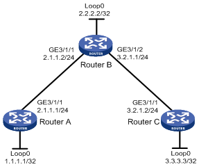
Configuration procedure
1. Assign IP addresses and masks to interfaces (see Figure 10). (Details not shown)
2. Enable IS-IS to advertise host routes with LSR IDs as destinations
# Configure Router A.
<RouterA> system-view
[RouterA] isis 1
[RouterA-isis-1] network-entity 00.0005.0000.0000.0001.00
[RouterA-isis-1] quit
[RouterA] interface GigabitEthernet 3/1/1
[RouterA-GigabitEthernet3/1/1] isis enable 1
[RouterA-GigabitEthernet3/1/1] quit
[RouterA] interface loopback 0
[RouterA-LoopBack0] isis enable 1
[RouterA-LoopBack0] quit
# Configure Router B.
<RouterB> system-view
[RouterB] isis 1
[RouterB-isis-1] network-entity 00.0005.0000.0000.0002.00
[RouterB-isis-1] quit
[RouterB] interface GigabitEthernet 3/1/1
[RouterB-GigabitEthernet3/1/1] isis enable 1
[RouterB-GigabitEthernet3/1/1] quit
[RouterB] interface GigabitEthernet 3/1/2
[RouterB-GigabitEthernet3/1/2] isis enable 1
[RouterB-GigabitEthernet3/1/2] quit
[RouterB] interface loopback 0
[RouterB-LoopBack0] isis enable 1
[RouterB-LoopBack0] quit
# Configure Router C.
<RouterB> system-view
[RouterC] isis 1
[RouterC-isis-1] network-entity 00.0005.0000.0000.0003.00
[RouterC-isis-1] quit
[RouterC] interface GigabitEthernet 3/1/1
[RouterC-GigabitEthernet3/1/1] isis enable 1
[RouterC-GigabitEthernet3/1/1] quit
[RouterC] interface loopback 0
[RouterC-LoopBack0] isis enable 1
[RouterC-LoopBack0] quit
Perform the display ip routing-table command on each router. You can see that all nodes learnt the host routes of other nodes with LSR IDs as destinations. Take Router A for example:
[RouterA] display ip routing-table
Routing Tables: Public
Destinations : 8 Routes : 8
Destination/Mask Proto Pre Cost NextHop Interface
1.1.1.1/32 Direct 0 0 127.0.0.1 InLoop0
2.1.1.0/24 Direct 0 0 2.1.1.1 GE3/1/1
2.1.1.1/32 Direct 0 0 127.0.0.1 InLoop0
2.2.2.2/32 ISIS 15 10 2.1.1.2 GE3/1/1
3.2.1.0/24 ISIS 15 20 2.1.1.2 GE3/1/1
3.3.3.3/32 ISIS 15 20 2.1.1.2 GE3/1/1
127.0.0.0/8 Direct 0 0 127.0.0.1 InLoop0
127.0.0.1/32 Direct 0 0 127.0.0.1 InLoop0
3. Configure MPLS TE basic capabilities
# Configure Router A.
[RouterA] mpls lsr-id 1.1.1.1
[RouterA] mpls
[RouterA-mpls] mpls te
[RouterA-mpls] quit
[RouterA] interface GigabitEthernet 3/1/1
[RouterA-GigabitEthernet3/1/1] mpls
[RouterA-GigabitEthernet3/1/1] mpls te
[RouterA-GigabitEthernet3/1/1] quit
# Configure Router B.
[RouterB] mpls lsr-id 2.2.2.2
[RouterB] mpls
[RouterB-mpls] mpls te
[RouterB-mpls] quit
[RouterB] interface GigabitEthernet 3/1/1
[RouterB-GigabitEthernet3/1/1] mpls
[RouterB-GigabitEthernet3/1/1] mpls te
[RouterB-GigabitEthernet3/1/1] quit
[RouterB] interface GigabitEthernet 3/1/2
[RouterB-GigabitEthernet3/1/2] mpls
[RouterB-GigabitEthernet3/1/2] mpls te
[RouterB-GigabitEthernet3/1/2] quit
# Configure Router C.
[RouterC] mpls lsr-id 3.3.3.3
[RouterC] mpls
[RouterC-mpls] mpls te
[RouterC-mpls] quit
[RouterC] interface GigabitEthernet 3/1/1
[RouterC-GigabitEthernet3/1/1] mpls
[RouterC-GigabitEthernet3/1/1] mpls te
[RouterC-GigabitEthernet3/1/1] quit
4. Configure an MPLS TE tunnel
# Configure an MPLS TE tunnel on Router A.
[RouterA] interface tunnel 3
[RouterA-Tunnel3] ip address 6.1.1.1 255.255.255.0
[RouterA-Tunnel3] tunnel-protocol mpls te
[RouterA-Tunnel3] destination 3.3.3.3
[RouterA-Tunnel3] mpls te tunnel-id 10
[RouterA-Tunnel3] mpls te signal-protocol static
[RouterA-Tunnel3] mpls te commit
[RouterA-Tunnel3] quit
5. Create a static CR-LSP
# Configure Router A as the ingress node of the static CR-LSP.
[RouterA] static-cr-lsp ingress tunnel3 destination 3.3.3.3 nexthop 2.1.1.2 out-label 20
# Configure Router B as the transit node on the static CR-LSP.
[RouterB] static-cr-lsp transit tunnel3 incoming-interface GigabitEthernet 3/1/1 in-label 20 nexthop 3.2.1.2 out-label 30
# Configure Router C as the egress node of the static CR-LSP.
[RouterC] static-cr-lsp egress tunnel3 incoming-interface GigabitEthernet 3/1/1 in-label 30
6. Verify the configuration
Perform the display interface tunnel command on Router A. You can find that the tunnel interface is up.
[RouterA] display interface tunnel
Tunnel3 current state: UP
Line protocol current state: UP
Description: Tunnel3 Interface
The Maximum Transmit Unit is 1500
Internet Address is 6.1.1.1/24 Primary
Encapsulation is TUNNEL, service-loopback-group ID not set
Tunnel source unknown, destination 3.3.3.3
Tunnel protocol/transport CR_LSP
Output queue : (Urgent queuing : Size/Length/Discards) 0/100/0
Output queue : (Protocol queuing : Size/Length/Discards) 0/500/0
Output queue : (FIFO queuing : Size/Length/Discards) 0/75/0
Last 300 seconds input: 0 bytes/sec, 0 packets/sec
Last 300 seconds output: 0 bytes/sec, 0 packets/sec
0 packets input, 0 bytes
0 input error
0 packets output, 0 bytes
0 output error
Perform the display mpls te tunnel command on each router to verify information about the MPLS TE tunnel.
[RouterA] display mpls te tunnel
LSP-Id Destination In/Out-If Name
1.1.1.1:1 3.3.3.3 -/GE3/1/1 Tunnel3
[RouterB] display mpls te tunnel
LSP-Id Destination In/Out-If Name
- - GE3/1/1/GE3/1/2 Tunnel3
[RouterC] display mpls te tunnel
LSP-Id Destination In/Out-If Name
- - GE3/1/1/- Tunnel3
Perform the display mpls lsp command or the display mpls static-cr-lsp command on each router to verify information about the static CR-LSP.
[RouterA] display mpls lsp
-------------------------------------------------------------------
LSP Information: STATIC CRLSP
-------------------------------------------------------------------
FEC In/Out Label In/Out IF Vrf Name
3.3.3.3/32 NULL/20 -/GE3/1/1
[RouterB] display mpls lsp
------------------------------------------------------------------
LSP Information: STATIC CRLSP
------------------------------------------------------------------
FEC In/Out Label In/Out IF Vrf Name
-/- 20/30 GE3/1/1/GE3/1/2
[RouterC] display mpls lsp
------------------------------------------------------------------
LSP Information: STATIC CRLSP
------------------------------------------------------------------
FEC In/Out Label In/Out IF Vrf Name
-/- 30/NULL GE3/1/1/-
[RouterA] display mpls static-cr-lsp
total static-cr-lsp : 1
Name FEC I/O Label I/O If State
Tunnel3 3.3.3.3/32 NULL/20 -/GE3/1/1 Up
[RouterB] display mpls static-cr-lsp
total static-cr-lsp : 1
Name FEC I/O Label I/O If State
Tunnel3 -/- 20/30 GE3/1/1/GE3/1/2 Up
[RouterC] display mpls static-cr-lsp
total static-cr-lsp : 1
Name FEC I/O Label I/O If State
Tunnel3 -/- 30/NULL GE3/1/1/- Up
|
|
NOTE: On an MPLS TE tunnel configured using a static CR-LSP, traffic is forwarded directly based on label at the transit nodes and egress node. Therefore, it is normal that the FEC field in the sample output is empty on Router B and Router C. |
7. Create a static route for routing MPLS TE tunnel traffic.
[RouterA] ip route-static 3.2.1.2 24 tunnel 3 preference 1
Perform the display ip routing-table command on Router A. You can find a static route entry with interface Tunnel3 as the outgoing interface.
MPLS TE tunnel using RSVP-TE configuration example
Network requirements
Router A, Router B, Router C, and Router D are running IS-IS and all of them are Level-2 routers.
Use RSVP-TE to create a TE tunnel with 2000 kbps of bandwidth from Router A to Router D, ensuring that the maximum bandwidth of each link that the tunnel traverses is 10000 kbps and the maximum reservable bandwidth is 5000 kbps.

|
Interface |
IP address |
Device |
Interface |
IP address |
|
|
Router A |
Loop0 |
1.1.1.9/32 |
Router C |
Loop0 |
3.3.3.9/32 |
|
|
GE 3/1/1 |
10.1.1.1/24 |
|
GE 3/1/1 |
30.1.1.1/24 |
|
Router B |
Loop0 |
2.2.2.9/32 |
|
POS 2/1/1 |
20.1.1.2/24 |
|
|
GE 3/1/1 |
10.1.1.2/24 |
Router D |
Loop0 |
4.4.4.9/32 |
|
|
POS 2/1/1 |
20.1.1.1/24 |
|
GE 3/1/1 |
30.1.1.2/24 |
Configuration procedure
1. Assign IP addresses and masks to interfaces (see Figure 11)
Details not shown
2. Enable IS-IS to advertise host routes with LSR IDs as destinations
# Configure Router A.
<RouterA> system-view
[RouterA] isis 1
[RouterA-isis-1] network-entity 00.0005.0000.0000.0001.00
[RouterA-isis-1] quit
[RouterA] interface GigabitEthernet 3/1/1
[RouterA-GigabitEthernet3/1/1] isis enable 1
[RouterA-GigabitEthernet3/1/1] isis circuit-level level-2
[RouterA-GigabitEthernet3/1/1] quit
[RouterA] interface loopback 0
[RouterA-LoopBack0] isis enable 1
[RouterA-LoopBack0] isis circuit-level level-2
[RouterA-LoopBack0] quit
# Configure Router B.
<RouterB> system-view
[RouterB] isis 1
[RouterB-isis-1] network-entity 00.0005.0000.0000.0002.00
[RouterB-isis-1] quit
[RouterB] interface GigabitEthernet 3/1/1
[RouterB-GigabitEthernet3/1/1] isis enable 1
[RouterB-GigabitEthernet3/1/1] isis circuit-level level-2
[RouterB-GigabitEthernet3/1/1] quit
[RouterB] interface pos 2/1/1
[RouterB-POS2/1/1] clock master
[RouterB-POS2/1/1] isis enable 1
[RouterB-POS2/1/1] isis circuit-level level-2
[RouterB-POS2/1/1] quit
[RouterB] interface loopback 0
[RouterB-LoopBack0] isis enable 1
[RouterB-LoopBack0] isis circuit-level level-2
[RouterB-LoopBack0] quit
# Configure Router C.
<RouterC> system-view
[RouterC] isis 1
[RouterC-isis-1] network-entity 00.0005.0000.0000.0003.00
[RouterC-isis-1] quit
[RouterC] interface GigabitEthernet 3/1/1
[RouterC-GigabitEthernet3/1/1] isis enable 1
[RouterC-GigabitEthernet3/1/1] isis circuit-level level-2
[RouterC-GigabitEthernet3/1/1] quit
[RouterC] interface pos 2/1/1
[RouterC-POS2/1/1] isis enable 1
[RouterC-POS2/1/1] isis circuit-level level-2
[RouterC-POS2/1/1] quit
[RouterC] interface loopback 0
[RouterC-LoopBack0] isis enable 1
[RouterC-LoopBack0] isis circuit-level level-2
[RouterC-LoopBack0] quit
# Configure Router D.
<RouterD> system-view
[RouterD] isis 1
[RouterD-isis-1] network-entity 00.0005.0000.0000.0004.00
[RouterD-isis-1] quit
[RouterD] interface GigabitEthernet 3/1/1
[RouterD-GigabitEthernet3/1/1] isis enable 1
[RouterD-GigabitEthernet3/1/1] isis circuit-level level-2
[RouterD-GigabitEthernet3/1/1] quit
[RouterD] interface loopback 0
[RouterD-LoopBack0] isis enable 1
[RouterD-LoopBack0] isis circuit-level level-2
[RouterD-LoopBack0] quit
Perform the display ip routing-table command on each router. You can see that all nodes learnt the host routes of other nodes with LSR IDs as destinations. Take Router A for example:
[RouterA] display ip routing-table
Routing Tables: Public
Destinations : 10 Routes : 10
Destination/Mask Proto Pre Cost NextHop Interface
1.1.1.9/32 Direct 0 0 127.0.0.1 InLoop0
2.2.2.9/32 ISIS 15 10 10.1.1.2 GE3/1/1
3.3.3.9/32 ISIS 15 20 10.1.1.2 GE3/1/1
4.4.4.9/32 ISIS 15 30 10.1.1.2 GE3/1/1
10.1.1.0/24 Direct 0 0 10.1.1.1 GE3/1/1
10.1.1.1/32 Direct 0 0 127.0.0.1 InLoop0
20.1.1.0/24 ISIS 15 20 10.1.1.2 GE3/1/1
30.1.1.0/24 ISIS 15 30 10.1.1.2 GE3/1/1
127.0.0.0/8 Direct 0 0 127.0.0.1 InLoop0
127.0.0.1/32 Direct 0 0 127.0.0.1 InLoop0
3. Configure MPLS TE basic capabilities, and enable RSVP-TE and CSPF
# Configure Router A.
[RouterA] mpls lsr-id 1.1.1.9
[RouterA] mpls
[RouterA-mpls] mpls te
[RouterA-mpls] mpls rsvp-te
[RouterA-mpls] mpls te cspf
[RouterA-mpls] quit
[RouterA] interface GigabitEthernet 3/1/1
[RouterA-GigabitEthernet3/1/1] mpls
[RouterA-GigabitEthernet3/1/1] mpls te
[RouterA-GigabitEthernet3/1/1] mpls rsvp-te
[RouterA-GigabitEthernet3/1/1] quit
# Configure Router B.
[RouterB] mpls lsr-id 2.2.2.9
[RouterB] mpls
[RouterB-mpls] mpls te
[RouterB-mpls] mpls rsvp-te
[RouterB-mpls] mpls te cspf
[RouterB-mpls] quit
[RouterB] interface GigabitEthernet 3/1/1
[RouterB-GigabitEthernet3/1/1] mpls
[RouterB-GigabitEthernet3/1/1] mpls te
[RouterB-GigabitEthernet3/1/1] mpls rsvp-te
[RouterB-GigabitEthernet3/1/1] quit
[RouterB] interface pos 2/1/1
[RouterB-POS2/1/1] mpls
[RouterB-POS2/1/1] mpls te
[RouterB-POS2/1/1] mpls rsvp-te
[RouterB-POS2/1/1] quit
# Configure Router C.
[RouterC] mpls lsr-id 3.3.3.9
[RouterC] mpls
[RouterC-mpls] mpls te
[RouterC-mpls] mpls rsvp-te
[RouterC-mpls] mpls te cspf
[RouterC-mpls] quit
[RouterC] interface GigabitEthernet 3/1/1
[RouterC-GigabitEthernet3/1/1] mpls
[RouterC-GigabitEthernet3/1/1] mpls te
[RouterC-GigabitEthernet3/1/1] mpls rsvp-te
[RouterC-GigabitEthernet3/1/1] quit
[RouterC] interface pos 2/1/1
[RouterC-POS2/1/1] mpls
[RouterC-POS2/1/1] mpls te
[RouterC-POS2/1/1] mpls rsvp-te
[RouterC-POS2/1/1] quit
# Configure Router D.
[RouterD] mpls lsr-id 4.4.4.9
[RouterD] mpls
[RouterD-mpls] mpls te
[RouterD-mpls] mpls rsvp-te
[RouterD-mpls] mpls te cspf
[RouterD-mpls] quit
[RouterD] interface GigabitEthernet 3/1/1
[RouterD-GigabitEthernet3/1/1] mpls
[RouterD-GigabitEthernet3/1/1] mpls te
[RouterD-GigabitEthernet3/1/1] mpls rsvp-te
[RouterD-GigabitEthernet3/1/1] quit
4. Configure IS-IS TE
# Configure Router A.
[RouterA] isis 1
[RouterA-isis-1] cost-style wide
[RouterA-isis-1] traffic-eng level-2
[RouterA-isis-1] quit
# Configure Router B.
[RouterB] isis 1
[RouterB-isis-1] cost-style wide
[RouterB-isis-1] traffic-eng level-2
[RouterB-isis-1] quit
# Configure Router C.
[RouterC] isis 1
[RouterC-isis-1] cost-style wide
[RouterC-isis-1] traffic-eng level-2
[RouterC-isis-1] quit
# Configure Router D.
[RouterD] isis 1
[RouterD-isis-1] cost-style wide
[RouterD-isis-1] traffic-eng level-2
[RouterD-isis-1] quit
5. Configure MPLS TE attributes of links
# Configure maximum link bandwidth and maximum reservable bandwidth on Router A.
[RouterA] interface GigabitEthernet 3/1/1
[RouterA-GigabitEthernet3/1/1] mpls te max-link-bandwidth 10000
[RouterA-GigabitEthernet3/1/1] mpls te max-reservable-bandwidth 5000
[RouterA-GigabitEthernet3/1/1] quit
# Configure maximum link bandwidth and maximum reservable bandwidth on Router B.
[RouterB] interface GigabitEthernet 3/1/1
[RouterB-GigabitEthernet3/1/1] mpls te max-link-bandwidth 10000
[RouterB-GigabitEthernet3/1/1] mpls te max-reservable-bandwidth 5000
[RouterB-GigabitEthernet3/1/1] quit
[RouterB] interface pos 2/1/1
[RouterB-POS2/1/1] mpls te max-link-bandwidth 10000
[RouterB-POS2/1/1] mpls te max-reservable-bandwidth 5000
[RouterB-POS2/1/1] quit
# Configure maximum link bandwidth and maximum reservable bandwidth on Router C.
[RouterC] interface GigabitEthernet 3/1/1
[RouterC-GigabitEthernet3/1/1] mpls te max-link-bandwidth 10000
[RouterC-GigabitEthernet3/1/1] mpls te max-reservable-bandwidth 5000
[RouterC-GigabitEthernet3/1/1] quit
[RouterC] interface pos 2/1/1
[RouterC-POS2/1/1] mpls te max-link-bandwidth 10000
[RouterC-POS2/1/1] mpls te max-reservable-bandwidth 5000
[RouterC-POS2/1/1] quit
# Configure maximum link bandwidth and maximum reservable bandwidth on Router D.
[RouterD] interface GigabitEthernet 3/1/1
[RouterD-GigabitEthernet3/1/1] mpls te max-link-bandwidth 10000
[RouterD-GigabitEthernet3/1/1] mpls te max-reservable-bandwidth 5000
[RouterD-GigabitEthernet3/1/1] quit
6. Create an MPLS TE tunnel
# Create an MPLS TE tunnel on Router A.
[RouterA] interface tunnel 4
[RouterA-Tunnel4] ip address 7.1.1.1 255.255.255.0
[RouterA-Tunnel4] tunnel-protocol mpls te
[RouterA-Tunnel4] destination 4.4.4.9
[RouterA-Tunnel4] mpls te tunnel-id 10
[RouterA-Tunnel4] mpls te signal-protocol rsvp-te
[RouterA-Tunnel4] mpls te bandwidth 2000
[RouterA-Tunnel4] mpls te commit
[RouterA-Tunnel4] quit
7. Verify the configuration
Perform the display interface tunnel command on Router A. You can find that the tunnel interface is up.
[RouterA] display interface tunnel
Tunnel4 current state: UP
Line protocol current state: UP
Description: Tunnel4 Interface
The Maximum Transmit Unit is 1500
Internet Address is 7.1.1.1/24 Primary
Encapsulation is TUNNEL, service-loopback-group ID not set
Tunnel source unknown, destination 4.4.4.9
Tunnel protocol/transport CR_LSP
Output queue : (Urgent queuing : Size/Length/Discards) 0/100/0
Output queue : (Protocol queuing : Size/Length/Discards) 0/500/0
Output queue : (FIFO queuing : Size/Length/Discards) 0/75/0
Last 300 seconds input: 0 bytes/sec, 0 packets/sec
Last 300 seconds output: 0 bytes/sec, 0 packets/sec
0 packets input, 0 bytes
0 input error
0 packets output, 0 bytes
0 output error
Perform the display mpls te tunnel-interface command on Router A to verify information about the MPLS TE tunnel.
[RouterA] display mpls te tunnel-interface
Tunnel Name : Tunnel4
Tunnel Desc : Tunnel4 Interface
Tunnel State Desc : CR-LSP is Up
Tunnel Attributes :
LSP ID : 1.1.1.9:3
Session ID : 10
Admin State : UP Oper State : UP
Ingress LSR ID : 1.1.1.9 Egress LSR ID: 4.4.4.9
Signaling Prot : RSVP Resv Style : SE
Class Type : CT0 Tunnel BW : 2000 kbps
Reserved BW : 2000 kbps
Setup Priority : 7 Hold Priority: 7
Affinity Prop/Mask : 0x0/0x0
Explicit Path Name : -
Tie-Breaking Policy : None
Metric Type : None
Record Route : Disabled Record Label : Disabled
FRR Flag : Disabled BackUpBW Flag: Not Supported
BackUpBW Type : - BackUpBW : -
Route Pinning : Disabled
Retry Limit : 10 Retry Interval: 10 sec
Reopt : Disabled Reopt Freq : -
Back Up Type : None
Back Up LSPID : -
Auto BW : Disabled Auto BW Freq : -
Min BW : - Max BW : -
Current Collected BW: -
Interfaces Protected: -
VPN Bind Type : NONE
VPN Bind Value : -
Car Policy : Disabled
Tunnel Group : Primary
Primary Tunnel : -
Backup Tunnel : -
Group Status : -
Oam Status : -
Perform the display mpls te cspf tedb all command on Router A to view information about links in TEDB.
[RouterA] display mpls te cspf tedb all
Maximum Node Supported: 128 Maximum Link Supported: 256
Current Total Node Number: 4 Current Total Link Number: 6
Id MPLS LSR-Id IGP Process-Id Area Link-Count
1 3.3.3.9 ISIS 1 Level-2 2
2 2.2.2.9 ISIS 1 Level-2 2
3 4.4.4.9 ISIS 1 Level-2 1
4 1.1.1.9 ISIS 1 Level-2 1
8. Create a static route for routing MPLS TE tunnel traffic
[RouterA] ip route-static 30.1.1.2 24 tunnel 4 preference 1
Perform the display ip routing-table command on Router A. You can find a static route entry with interface Tunnel4 as the outgoing interface.
Configuration example of inter-AS MPLS TE tunnel using RSVP-TE
Network requirements
Router A and Router B are in AS 100, and they run OSPF as the IGP. Router C and Router D are in AS 200, and they run OSPF as the IGP.
Establish an EBGP connection between ASBRs Router B and Router C. Redistribute BGP routes into OSPF and OSPF routes into BGP, so that a route is available between AS 100 and AS 200.
Establish an MPLS TE tunnel between Router A and Router D by using RSVP-TE, with the bandwidth being 2000 kbps.
Along the tunnel, the maximum link bandwidth is 10000 kbps and maximum reservable bandwidth is 5000 kbps.
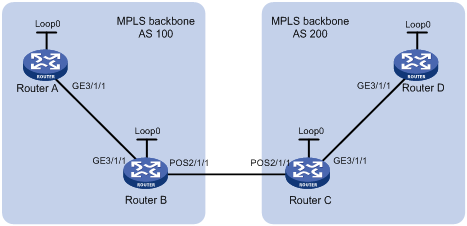
|
Device |
Interface |
IP address |
Device |
Interface |
IP address |
|
Router A |
Loop0 |
1.1.1.9/32 |
Router C |
Loop0 |
3.3.3.9/32 |
|
|
GE3/1/1 |
10.1.1.1/24 |
|
GE3/1/1 |
30.1.1.1/24 |
|
Router B |
Loop0 |
2.2.2.9/32 |
|
POS2/1/1 |
20.1.1.2/24 |
|
|
GE3/1/1 |
10.1.1.2/24 |
Router D |
Loop0 |
4.4.4.9/32 |
|
|
POS2/1/1 |
20.1.1.1/24 |
|
GE3/1/1 |
30.1.1.2/24 |
Configuration procedure
1. Assign IP addresses and masks to interfaces (see Figure 12)
2. Configure OSPF to advertise routes within the ASs
# Configure OSPF on Router A.
<RouterA> system-view
[RouterA] ospf
[RouterA-ospf-1] area 0
[RouterA-ospf-1-area-0.0.0.0] network 10.1.1.0 0.0.0.255
[RouterA-ospf-1-area-0.0.0.0] network 1.1.1.9 0.0.0.0
[RouterA-ospf-1-area-0.0.0.0] quit
[RouterA-ospf-1] quit
# Configure OSPF on Router B.
<RouterB> system-view
[RouterB] ospf
[RouterB-ospf-1] import-route direct
[RouterB-ospf-1] import-route bgp
[RouterB-ospf-1] area 0
[RouterB-ospf-1-area-0.0.0.0] network 10.1.1.0 0.0.0.255
[RouterB-ospf-1-area-0.0.0.0] network 2.2.2.9 0.0.0.0
[RouterB-ospf-1-area-0.0.0.0] quit
[RouterB-ospf-1] quit
# Configure OSPF on Router C.
<RouterC> system-view
[RouterC] ospf
[RouterC-ospf-1] import-route direct
[RouterC-ospf-1] import-route bgp
[RouterC-ospf-1] area 0
[RouterC-ospf-1-area-0.0.0.0] network 30.1.1.0 0.0.0.255
[RouterC-ospf-1-area-0.0.0.0] network 3.3.3.9 0.0.0.0
[RouterC-ospf-1-area-0.0.0.0] quit
[RouterC-ospf-1] quit
# Configure OSPF on Router D.
<RouterD> system-view
[RouterD] ospf
[RouterD-ospf-1] area 0
[RouterD-ospf-1-area-0.0.0.0] network 30.1.1.0 0.0.0.255
[RouterD-ospf-1-area-0.0.0.0] network 4.4.4.9 0.0.0.0
[RouterD-ospf-1-area-0.0.0.0] quit
[RouterD-ospf-1] quit
After the configurations, execute the display ip routing-table command on each device. The output shows that each device has learned the route to the LSR ID of the other device in the same AS. Take Router A as an example:
[RouterA] display ip routing-table
Routing Tables: Public
Destinations : 6 Routes : 6
Destination/Mask Proto Pre Cost NextHop Interface
1.1.1.9/32 Direct 0 0 127.0.0.1 InLoop0
2.2.2.9/32 OSPF 10 1 10.1.1.2 GE3/1/1
10.1.1.0/24 Direct 0 0 10.1.1.1 GE3/1/1
10.1.1.1/32 Direct 0 0 127.0.0.1 InLoop0
127.0.0.0/8 Direct 0 0 127.0.0.1 InLoop0
127.0.0.1/32 Direct 0 0 127.0.0.1 InLoop0
3. Configure BGP on Router B and Router C and redistribute routes, ensuring that the ASs can communicate with each other.
# Configure Router B.
[RouterB] bgp 100
[RouterB-bgp] peer 20.1.1.2 as-number 200
[RouterB-bgp] import-route ospf
[RouterB-bgp] import-route direct
[RouterB-bgp] quit
# Configure Router C.
[RouterC] bgp 200
[RouterC-bgp] peer 20.1.1.1 as-number 100
[RouterC-bgp] import-route ospf
[RouterC-bgp] import-route direct
[RouterC-bgp] quit
After the configuration, execute the display ip routing-table command on each device. The output shows that each device has learned the routes to the outside of the AS. Take Router A as an example:
[RouterA] display ip routing-table
Routing Tables: Public
Destinations : 10 Routes : 10
Destination/Mask Proto Pre Cost NextHop Interface
1.1.1.9/32 Direct 0 0 127.0.0.1 InLoop0
2.2.2.9/32 OSPF 10 1 10.1.1.2 GE3/1/1
3.3.3.9/32 O_ASE 150 1 10.1.1.2 GE3/1/1
4.4.4.9/32 O_ASE 150 1 10.1.1.2 GE3/1/1
10.1.1.0/24 Direct 0 0 10.1.1.1 GE3/1/1
10.1.1.1/32 Direct 0 0 127.0.0.1 InLoop0
20.1.1.0/24 O_ASE 150 1 10.1.1.2 GE3/1/1
30.1.1.0/24 O_ASE 150 1 10.1.1.2 GE3/1/1
127.0.0.0/8 Direct 0 0 127.0.0.1 InLoop0
127.0.0.1/32 Direct 0 0 127.0.0.1 InLoop0
4. Configure MPLS TE basic capabilities, and enable RSVP-TE and CSPF
# Configure Router A.
[RouterA] mpls lsr-id 1.1.1.9
[RouterA] mpls
[RouterA-mpls] mpls te
[RouterA-mpls] mpls rsvp-te
[RouterA-mpls] mpls te cspf
[RouterA-mpls] quit
[RouterA] interface GigabitEthernet 3/1/1
[RouterA-GigabitEthernet3/1/1] mpls
[RouterA-GigabitEthernet3/1/1] mpls te
[RouterA-GigabitEthernet3/1/1] mpls rsvp-te
[RouterA-GigabitEthernet3/1/1] quit
# Configure Router B.
[RouterB] mpls lsr-id 2.2.2.9
[RouterB] mpls
[RouterB-mpls] mpls te
[RouterB-mpls] mpls rsvp-te
[RouterB-mpls] mpls te cspf
[RouterB-mpls] quit
[RouterB] interface GigabitEthernet 3/1/1
[RouterB-GigabitEthernet3/1/1] mpls
[RouterB-GigabitEthernet3/1/1] mpls te
[RouterB-GigabitEthernet3/1/1] mpls rsvp-te
[RouterB-GigabitEthernet3/1/1] quit
[RouterB] interface POS 2/1/1
[RouterB-POS2/1/1] mpls
[RouterB-POS2/1/1] mpls te
[RouterB-POS2/1/1] mpls rsvp-te
[RouterB-POS2/1/1] quit
# Configure Router C.
[RouterC] mpls lsr-id 3.3.3.9
[RouterC] mpls
[RouterC-mpls] mpls te
[RouterC-mpls] mpls rsvp-te
[RouterC-mpls] mpls te cspf
[RouterC-mpls] quit
[RouterC] interface GigabitEthernet 3/1/1
[RouterC-GigabitEthernet3/1/1] mpls
[RouterC-GigabitEthernet3/1/1] mpls te
[RouterC-GigabitEthernet3/1/1] mpls rsvp-te
[RouterC-GigabitEthernet3/1/1] quit
[RouterC] interface POS 2/1/1
[RouterC-POS2/1/1] mpls
[RouterC-POS2/1/1] mpls te
[RouterC-POS2/1/1] mpls rsvp-te
[RouterC-POS2/1/1] quit
# Configure Router D.
[RouterD] mpls lsr-id 4.4.4.9
[RouterD] mpls
[RouterD-mpls] mpls te
[RouterD-mpls] mpls rsvp-te
[RouterD-mpls] mpls te cspf
[RouterD-mpls] quit
[RouterD] interface GigabitEthernet 3/1/1
[RouterD-GigabitEthernet3/1/1] mpls
[RouterD-GigabitEthernet3/1/1] mpls te
[RouterD-GigabitEthernet3/1/1] mpls rsvp-te
[RouterD-GigabitEthernet3/1/1] quit
5. Configure OSPF TE
# Configure Router A.
[RouterA] ospf
[RouterA-ospf-1] opaque-capability enable
[RouterA-ospf-1] area 0
[RouterA-ospf-1-area-0.0.0.0] mpls-te enable
[RouterA-ospf-1-area-0.0.0.0] quit
[RouterA-ospf-1] quit
# Configure Router B.
[RouterB] ospf
[RouterB-ospf-1] opaque-capability enable
[RouterB-ospf-1] area 0
[RouterB-ospf-1-area-0.0.0.0] mpls-te enable
[RouterB-ospf-1-area-0.0.0.0] quit
[RouterB-ospf-1] quit
# Configure Router C.
[RouterC] ospf
[RouterC-ospf-1] opaque-capability enable
[RouterC-ospf-1] area 0
[RouterC-ospf-1-area-0.0.0.0] mpls-te enable
[RouterC-ospf-1-area-0.0.0.0] quit
[RouterC-ospf-1] quit
# Configure Router D.
[RouterD] ospf
[RouterD-ospf-1] opaque-capability enable
[RouterD-ospf-1] area 0
[RouterD-ospf-1-area-0.0.0.0] mpls-te enable
[RouterD-ospf-1-area-0.0.0.0] quit
[RouterD-ospf-1] quit
6. Configure a loose explicit route
# Configure a loose explicit route on Router A.
[RouterA] explicit-path atod enable
[RouterA-explicit-path-atod] next hop 10.1.1.2 include loose
[RouterA-explicit-path-atod] next hop 20.1.1.2 include loose
[RouterA-explicit-path-atod] next hop 30.1.1.2 include loose
[RouterA-explicit-path-atod] quit
7. Configure MPLS TE attributes of links
# Configure the maximum link bandwidth and maximum reservable bandwidth on Router A.
[RouterA] interface GigabitEthernet 3/1/1
[RouterA-GigabitEthernet3/1/1] mpls te max-link-bandwidth 10000
[RouterA-GigabitEthernet3/1/1] mpls te max-reservable-bandwidth 5000
[RouterA-GigabitEthernet3/1/1] quit
# Configure the maximum link bandwidth and maximum reservable bandwidth on Router B.
[RouterB] interface GigabitEthernet 3/1/1
[RouterB-GigabitEthernet3/1/1] mpls te max-link-bandwidth 10000
[RouterB-GigabitEthernet3/1/1] mpls te max-reservable-bandwidth 5000
[RouterB-GigabitEthernet3/1/1] quit
[RouterB] interface POS 2/1/1
[RouterB-POS2/1/1] mpls te max-link-bandwidth 10000
[RouterB-POS2/1/1] mpls te max-reservable-bandwidth 5000
[RouterB-POS2/1/1] quit
# Configure the maximum link bandwidth and maximum reservable bandwidth on Router C.
[RouterC] interface GigabitEthernet 3/1/1
[RouterC-GigabitEthernet3/1/1] mpls te max-link-bandwidth 10000
[RouterC-GigabitEthernet3/1/1] mpls te max-reservable-bandwidth 5000
[RouterC-GigabitEthernet3/1/1] quit
[RouterC] interface POS 2/1/1
[RouterC-POS2/1/1] mpls te max-link-bandwidth 10000
[RouterC-POS2/1/1] mpls te max-reservable-bandwidth 5000
[RouterC-POS2/1/1] quit
# Configure the maximum link bandwidth and maximum reservable bandwidth on Router D.
[RouterD] interface GigabitEthernet 3/1/1
[RouterD-GigabitEthernet3/1/1] mpls te max-link-bandwidth 10000
[RouterD-GigabitEthernet3/1/1] mpls te max-reservable-bandwidth 5000
[RouterD-GigabitEthernet3/1/1] quit
8. Create an MPLS TE tunnel
# Create an MPLS TE tunnel on Router A.
[RouterA] interface tunnel 1
[RouterA-Tunnel1] ip address 7.1.1.1 255.255.255.0
[RouterA-Tunnel1] tunnel-protocol mpls te
[RouterA-Tunnel1] destination 4.4.4.9
[RouterA-Tunnel1] mpls te tunnel-id 10
[RouterA-Tunnel1] mpls te signal-protocol rsvp-te
[RouterA-Tunnel1] mpls te bandwidth 2000
[RouterA-Tunnel1] mpls te path explicit-path atod preference 5
[RouterA-Tunnel1] mpls te commit
[RouterA-Tunnel1] quit
9. Verify the configuration
Perform the display interface tunnel command on Router A. The output shows that the tunnel interface is up.
[RouterA] display interface tunnel 1
Tunnel1 current state: UP
Line protocol current state: UP
Description: Tunnel1 Interface
The Maximum Transmit Unit is 64000
Internet Address is 7.1.1.1/24 Primary
Encapsulation is TUNNEL, service-loopback-group ID not set.
Tunnel source unknown, destination 4.4.4.9
Tunnel protocol/transport CR_LSP
Output queue : (Urgent queuing : Size/Length/Discards) 0/100/0
Output queue : (Protocol queuing : Size/Length/Discards) 0/500/0
Output queue : (FIFO queuing : Size/Length/Discards) 0/75/0
Last clearing of counters: Never
Last 300 seconds input: 0 bytes/sec, 0 packets/sec
Last 300 seconds output: 0 bytes/sec, 0 packets/sec
0 packets input, 0 bytes
0 input error
0 packets output, 0 bytes
0 output error
Perform the display mpls te tunnel-interface command on Router A to view the detailed information of the MPLS TE tunnel.
[RouterA] display mpls te tunnel-interface
Tunnel Name : Tunnel1
Tunnel Desc : Tunnel1 Interface
Tunnel State Desc : CR-LSP is Up
Tunnel Attributes :
LSP ID : 1.1.1.9:2
Session ID : 10
Admin State : UP Oper State : UP
Ingress LSR ID : 1.1.1.9 Egress LSR ID: 4.4.4.9
Signaling Prot : RSVP Resv Style : SE
Class Type : CT0 Tunnel BW : 2000 kbps
Reserved BW : 2000 kbps
Setup Priority : 7 Hold Priority: 7
Affinity Prop/Mask : 0x0/0x0
Explicit Path Name : atod
Tie-Breaking Policy : None
Metric Type : None
Loop Detection : Disabled
Record Route : Disabled Record Label : Disabled
FRR Flag : Disabled BackUpBW Flag: Not Supported
BackUpBW Type : - BackUpBW : -
Route Pinning : Disabled
Retry Limit : 10 Retry Interval: 2 sec
Reopt : Disabled Reopt Freq : -
Back Up Type : None
Back Up LSPID : -
Auto BW : Disabled Auto BW Freq : -
Min BW : - Max BW : -
Current Collected BW: -
Interfaces Protected: -
VPN Bind Type : NONE
VPN Bind Value : -
Car Policy : Disabled
Tunnel Group : Primary
Primary Tunnel : -
Backup Tunnel : -
Group Status : -
Oam Status : -
Perform the display mpls te cspf tedb all command on Router A to view information about links in TEDB.
[RouterA] display mpls te cspf tedb all
Maximum Node Supported: 128 Maximum Link Supported: 256
Current Total Node Number: 2 Current Total Link Number: 2
Id MPLS LSR-Id IGP Process-Id Area Link-Count
1 1.1.1.9 OSPF 1 0 1
2 2.2.2.9 OSPF 1 0 1
10. Create a static route for routing MPLS TE tunnel traffic
[RouterA] ip route-static 30.1.1.2 24 tunnel 1 preference 1
Perform the display ip routing-table command on Router A. The output shows a static route entry with interface Tunnel 1 as the outgoing interface.
[RouterA] display ip routing-table
Routing Tables: Public
Destinations : 14 Routes : 14
Destination/Mask Proto Pre Cost NextHop Interface
1.1.1.9/32 Direct 0 0 127.0.0.1 InLoop0
2.2.2.9/32 OSPF 10 1 10.1.1.2 GE3/1/1
3.3.3.9/32 O_ASE 150 1 10.1.1.2 GE3/1/1
4.4.4.9/32 O_ASE 150 1 10.1.1.2 GE3/1/1
7.1.1.0/24 Direct 0 0 7.1.1.1 Tun1
7.1.1.1/32 Direct 0 0 127.0.0.1 InLoop0
10.1.1.0/24 Direct 0 0 10.1.1.1 GE3/1/1
10.1.1.1/32 Direct 0 0 127.0.0.1 InLoop0
20.1.1.0/24 O_ASE 150 1 10.1.1.2 GE3/1/1
30.1.1.0/24 Static 1 0 7.1.1.1 Tun1
127.0.0.0/8 Direct 0 0 127.0.0.1 InLoop0
127.0.0.1/32 Direct 0 0 127.0.0.1 InLoop0
RSVP-TE GR configuration example
Network requirements
Router A, Router B and Router C are running IS-IS. All of them are Level-2 routers and support RSVP hello extension.
Use RSVP-TE to create a TE tunnel from Router A to Router C.
Router A, Router B and Router C are RSVP-TE neighbors. With GR capability, each of them can provide GR helper support when another is GR restarting.
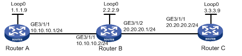
Configuration procedure
1. Assign IP addresses and masks to interfaces (see Figure 13)
Details not shown
2. Enable IS-IS to advertise host routes with LSR IDs as destinations
Details not shown
3. Configure MPLS TE basic capabilities, and enable RSVP-TE and RSVP hello extension
# Configure Router A.
<RouterA> system-view
[RouterA] mpls lsr-id 1.1.1.9
[RouterA] mpls
[RouterA-mpls] mpls te
[RouterA-mpls] mpls rsvp-te
[RouterA-mpls] mpls rsvp-te hello
[RouterA-mpls] interface GigabitEthernet 3/1/1
[RouterA-GigabitEthernet3/1/1] mpls
[RouterA-GigabitEthernet3/1/1] mpls te
[RouterA-GigabitEthernet3/1/1] mpls rsvp-te
[RouterA-GigabitEthernet3/1/1] mpls rsvp-te hello
[RouterA-GigabitEthernet3/1/1] quit
# Configure Router B.
<RouterB> system-view
[RouterB] mpls lsr-id 2.2.2.9
[RouterB] mpls
[RouterB-mpls] mpls te
[RouterB-mpls] mpls rsvp-te
[RouterB-mpls] mpls rsvp-te hello
[RouterB-mpls] interface GigabitEthernet 3/1/1
[RouterB-GigabitEthernet3/1/1] mpls
[RouterB-GigabitEthernet3/1/1] mpls te
[RouterB-GigabitEthernet3/1/1] mpls rsvp-te
[RouterB-GigabitEthernet3/1/1] mpls rsvp-te hello
[RouterB-GigabitEthernet3/1/1] quit
[RouterB] interface GigabitEthernet 3/1/2
[RouterB-GigabitEthernet3/1/2] mpls
[RouterB-GigabitEthernet3/1/2] mpls te
[RouterB-GigabitEthernet3/1/2] mpls rsvp-te
[RouterB-GigabitEthernet3/1/2] mpls rsvp-te hello
[RouterB-GigabitEthernet3/1/2] quit
# Configure Router C.
<RouterC> system-view
[RouterC] mpls lsr-id 3.3.3.9
[RouterC] mpls
[RouterC-mpls] mpls te
[RouterC-mpls] mpls rsvp-te
[RouterC-mpls] mpls rsvp-te hello
[RouterC-mpls] interface GigabitEthernet 3/1/1
[RouterC-GigabitEthernet3/1/1] mpls
[RouterC-GigabitEthernet3/1/1] mpls te
[RouterC-GigabitEthernet3/1/1] mpls rsvp-te
[RouterC-GigabitEthernet3/1/1] mpls rsvp-te hello
[RouterC-GigabitEthernet3/1/1] quit
4. Configure IS-IS TE
Details not shown
5. Configure the MPLS TE tunnel
Details not shown
6. Configure RSVP-TE GR
# Configure Router A.
<RouterA> system-view
[RouterA] mpls
[RouterA-mpls] mpls rsvp-te graceful-restart
# Configure Router B.
<RouterB> system-view
[RouterB] mpls
[RouterB-mpls] mpls rsvp-te graceful-restart
# Configure Router C.
<RouterC> system-view
[RouterC] mpls
[RouterC-mpls] mpls rsvp-te graceful-restart
7. Verify the configuration
After previous configurations, a tunnel is created between Router A and Router C. Issuing the following command, you will see that the neighbor’s GR status is Ready.
<RouterA> display mpls rsvp-te peer
Interface GigabitEthernet3/1/1
Neighbor Addr: 10.1.1.2
SrcInstance: 880 NbrSrcInstance: 5017
PSB Count: 0 RSB Count: 1
Hello Type Sent: REQ Neighbor Hello Extension: ENABLE
SRefresh Enable: NO
Graceful Restart State: Ready
Restart Time: 120 Sec Recovery Time: 300 Sec
MPLS RSVP-TE and BFD cooperation configuration example
Network requirements
Router A and Router B are connected directly. Enable MPLS RSVP-TE BFD on the interfaces connecting the two routers, and run OSPF on the routers to ensure reachability at the network layer.
If the physical link between Router A and Router B fails, BFD can detect the failure quickly and inform MPLS RSVP-TE of the failure.
Figure 14 Network diagram
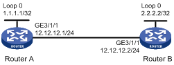
Configuration procedure
1. Configure MPLS RSVP-TE basic capabilities
# Configure Router A.
<RouterA> system-view
[RouterA] mpls lsr-id 1.1.1.1
[RouterA] mpls
[RouterA-mpls] mpls te
[RouterA-mpls] mpls rsvp-te
[RouterA-mpls] quit
[RouterA] interface GigabitEthernet 3/1/1
[RouterA-GigabitEthernet3/1/1] mpls
[RouterA-GigabitEthernet3/1/1] mpls te
[RouterA-GigabitEthernet3/1/1] mpls rsvp-te
[RouterA-GigabitEthernet3/1/1] mpls rsvp-te bfd enable
[RouterA-GigabitEthernet3/1/1] quit
# Configure Router B.
<RouterB> system-view
[RouterB] mpls lsr-id 2.2.2.2
[RouterB] mpls
[RouterB-mpls] mpls te
[RouterB-mpls] mpls rsvp-te
[RouterB-mpls] quit
[RouterB] interface GigabitEthernet 3/1/1
[RouterB-GigabitEthernet3/1/1] mpls
[RouterB-GigabitEthernet3/1/1] mpls te
[RouterB-GigabitEthernet3/1/1] mpls rsvp-te
[RouterB-GigabitEthernet3/1/1] mpls rsvp-te bfd enable
[RouterB-GigabitEthernet3/1/1] quit
2. Configure OSPF
# Configure Router A.
<RouterA> system-view
[RouterA] ospf
[Router-A-ospf-1] area 0
[Router-A-ospf-1-area-0.0.0.0] network 12.12.12.1 0.0.0.255
[Router-A-ospf-1-area-0.0.0.0] network 1.1.1.1 0.0.0.0
[Router-A-ospf-1-area-0.0.0.0] quit
[Router-A-ospf-1] quit
# Configure Router B.
<RouterB>system-view
[RouterB] ospf
[RouterB-ospf-1] area 0
[RouterB-ospf-1-area-0.0.0.0] network 12.12.12.2 0.0.0.255
[RouterB-ospf-1-area-0.0.0.0] network 2.2.2.2 0.0.0.0
[RouterB-ospf-1-area-0.0.0.0] quit
[RouterB-ospf-1] quit
3. Configure IP addresses for the interfaces
# Configure Router A.
[RouterA] interface GigabitEthernet 3/1/1
[RouterA-GigabitEthernet3/1/1] ip address 12.12.12.1 24
[RouterA-GigabitEthernet3/1/1] quit
# Configure Router B.
[RouterB] interface GigabitEthernet 3/1/1
[RouterB-GigabitEthernet3/1/1] ip address 12.12.12.2 24
4. Configure the MPLS TE tunnel
# Configure an RSVP-TE tunnel between Router A and Router B.
[RouterA] interface tunnel 1
[RouterA-Tunnel1] ip address 10.10.10.1 24
[RouterA-Tunnel1] tunnel-protocol mpls te
[RouterA-Tunnel1] destination 2.2.2.2
[RouterA-Tunnel1] mpls te tunnel-id 10
[RouterA-Tunnel1] mpls te signal-protocol rsvp-te
[RouterA-Tunnel1] mpls te commit
[RouterA-Tunnel1] return
5. Verify the configuration
Display the detailed information of the BFD session between Router A and Router B.
<RouterA> display bfd session verbose
Total Session Num: 1 Init Mode: Active
Session Working Under Ctrl Mode:
Local Discr: 19 Remote Discr: 18
Source IP: 12.12.12.1 Destination IP: 12.12.12.2
Session State: Up Interface: GigabitEthernet3/1/1
Min Trans Inter: 400ms Act Trans Inter: 400ms
Min Recv Inter: 400ms Act Detect Inter: 2000ms
Running Up for: 00:00:01 Auth mode: None
Connect Type: Direct Board Num: 6
Protocol: RSVP
Diag Info: No Diagnostic
MPLS TE using CR-LDP configuration example
Network requirements
Router A, Router B, Router C and Router D are running OSPF and all of them are in area 0.
Use CR-LDP to create a TE tunnel from Router A to Router D, ensuring that the maximum bandwidth of each link that the tunnel traverses is 10000 kbps and the maximum reservable bandwidth is 5000 kbps.

|
Device |
Interface |
IP address |
Device |
Interface |
IP address |
|
Router A |
Loop0 |
1.1.1.9/32 |
Router D |
Loop0 |
4.4.4.9/32 |
|
|
GE 3/1/1 |
10.1.1.1/24 |
|
GE 3/1/1 |
30.1.1.2/24 |
|
Router B |
Loop0 |
2.2.2.9/32 |
Router C |
Loop0 |
3.3.3.9/32 |
|
|
GE 3/1/1 |
10.1.1.2/24 |
|
GE 3/1/1 |
30.1.1.1/24 |
|
|
GE 3/1/2 |
20.1.1.1/24 |
|
GE 3/1/2 |
20.1.1.2/24 |
Configuration procedure
1. Assign IP addresses and masks to interfaces (see Figure 15)
Details not shown
2. Enable OSPF to advertise host routes with LSR IDs as destinations
Details not shown
After configuration, you can perform the display ip routing-table command on each router. You can see that all nodes learnt the host routes of other nodes with LSR IDs as destinations.
3. Configure MPLS TE basic capabilities, and enable CSPF
# Configure Router A.
[RouterA] mpls lsr-id 1.1.1.9
[RouterA] mpls
[RouterA-mpls] mpls te
[RouterA-mpls] mpls te cspf
[RouterA-mpls] quit
[RouterA] interface GigabitEthernet 3/1/1
[RouterA-GigabitEthernet3/1/1] mpls
[RouterA-GigabitEthernet3/1/1] mpls te
[RouterA-GigabitEthernet3/1/1] quit
# Configure Router B.
[RouterB] mpls lsr-id 2.2.2.9
[RouterB] mpls
[RouterB-mpls] mpls te
[RouterB-mpls] mpls te cspf
[RouterB-mpls] quit
[RouterB] interface GigabitEthernet 3/1/1
[RouterB-GigabitEthernet3/1/1] mpls
[RouterB-GigabitEthernet3/1/1] mpls te
[RouterB-GigabitEthernet3/1/1] quit
[RouterB] interface GigabitEthernet 3/1/2
[RouterB-GigabitEthernet3/1/2] mpls
[RouterB-GigabitEthernet3/1/2] mpls te
[RouterB-GigabitEthernet3/1/2] quit
# Configure Router C.
[RouterC] mpls lsr-id 3.3.3.9
[RouterC] mpls
[RouterC-mpls] mpls te
[RouterC-mpls] mpls te cspf
[RouterC-mpls] quit
[RouterC] interface GigabitEthernet 3/1/1
[RouterC-GigabitEthernet3/1/1] mpls
[RouterC-GigabitEthernet3/1/1] mpls te
[RouterC-GigabitEthernet3/1/1] quit
[RouterC] interface GigabitEthernet 3/1/2
[RouterC-GigabitEthernet3/1/2] mpls
[RouterC-GigabitEthernet3/1/2] mpls te
[RouterC-GigabitEthernet3/1/2] quit
# Configure Router D.
[RouterD] mpls lsr-id 4.4.4.9
[RouterD] mpls
[RouterD-mpls] mpls te
[RouterD-mpls] mpls te cspf
[RouterD-mpls] quit
[RouterD] interface GigabitEthernet 3/1/1
[RouterD-GigabitEthernet3/1/1] mpls
[RouterD-GigabitEthernet3/1/1] mpls te
[RouterD-GigabitEthernet3/1/1] quit
4. Configure OSPF TE
# Configure Router A.
[RouterA] ospf
[RouterA-ospf-1] opaque-capability enable
[RouterA-ospf-1] area 0
[RouterA-ospf-1-area-0.0.0.0] mpls-te enable
[RouterA-ospf-1-area-0.0.0.0] quit
[RouterA-ospf-1] quit
# Configure Router B.
[RouterB] ospf
[RouterB-ospf-1] opaque-capability enable
[RouterB-ospf-1] area 0
[RouterB-ospf-1-area-0.0.0.0] mpls-te enable
[RouterB-ospf-1-area-0.0.0.0] quit
[RouterB-ospf-1] quit
# Configure Router C.
[RouterC] ospf
[RouterC-ospf-1] opaque-capability enable
[RouterC-ospf-1] area 0
[RouterC-ospf-1-area-0.0.0.0] mpls-te enable
[RouterC-ospf-1-area-0.0.0.0] quit
[RouterC-ospf-1] quit
# Configure Router D.
[RouterD] ospf
[RouterD-ospf-1] opaque-capability enable
[RouterD-ospf-1] area 0
[RouterD-ospf-1-area-0.0.0.0] mpls-te enable
[RouterD-ospf-1-area-0.0.0.0] quit
[RouterD-ospf-1] quit
5. Configure MPLS TE attributes of links
# Configure maximum link bandwidth and maximum reservable bandwidth on Router A.
[RouterA] interface GigabitEthernet 3/1/1
[RouterA-GigabitEthernet3/1/1] mpls te max-link-bandwidth 10000
[RouterA-GigabitEthernet3/1/1] mpls te max-reservable-bandwidth 5000
[RouterA-GigabitEthernet3/1/1] quit
# Configure maximum link bandwidth and maximum reservable bandwidth on Router B.
[RouterB] interface GigabitEthernet 3/1/1
[RouterB-GigabitEthernet3/1/1] mpls te max-link-bandwidth 10000
[RouterB-GigabitEthernet3/1/1] mpls te max-reservable-bandwidth 5000
[RouterB-GigabitEthernet3/1/1] quit
[RouterB] interface GigabitEthernet 3/1/2
[RouterB-GigabitEthernet3/1/2] mpls te max-link-bandwidth 10000
[RouterB-GigabitEthernet3/1/2] mpls te max-reservable-bandwidth 5000
[RouterB-GigabitEthernet3/1/2] quit
# Configure maximum link bandwidth and maximum reservable bandwidth on Router C.
[RouterC] interface GigabitEthernet 3/1/1
[RouterC-GigabitEthernet3/1/1] mpls te max-link-bandwidth 10000
[RouterC-GigabitEthernet3/1/1] mpls te max-reservable-bandwidth 5000
[RouterC-GigabitEthernet3/1/1] quit
[RouterC] interface GigabitEthernet 3/1/2
[RouterC-GigabitEthernet3/1/2] mpls te max-link-bandwidth 10000
[RouterC-GigabitEthernet3/1/2] mpls te max-reservable-bandwidth 5000
[RouterC-GigabitEthernet3/1/2] quit
# Configure maximum link bandwidth and maximum reservable bandwidth on Router D.
[RouterD] interface GigabitEthernet 3/1/1
[RouterD-GigabitEthernet3/1/1] mpls te max-link-bandwidth 10000
[RouterD-GigabitEthernet3/1/1] mpls te max-reservable-bandwidth 5000
[RouterD-GigabitEthernet3/1/1] quit
Perform the display mpls te cspf tedb all command on each router to view information about links in TEDB. Take Router A for example:
[RouterA] display mpls te cspf tedb all
Maximum Node Supported: 128 Maximum Link Supported: 256
Current Total Node Number: 4 Current Total Link Number: 6
Id MPLS LSR-Id IGP Process-Id Area Link-Count
1 2.2.2.9 OSPF 1 0 2
2 3.3.3.9 OSPF 1 0 2
3 4.4.4.9 OSPF 1 0 1
4 1.1.1.9 OSPF 1 0 1
6. Configure LDP
# Configure Router A.
[RouterA] mpls ldp
[RouterA-mpls-ldp] quit
[RouterA] interface GigabitEthernet 3/1/1
[RouterA-GigabitEthernet3/1/1] mpls ldp
[RouterA-GigabitEthernet3/1/1] quit
# Configure Router B.
[RouterB] mpls ldp
[RouterB-mpls-ldp] quit
[RouterB] interface GigabitEthernet 3/1/1
[RouterB-GigabitEthernet3/1/1] mpls ldp
[RouterB-GigabitEthernet3/1/1] quit
[RouterB] interface GigabitEthernet 3/1/2
[RouterB-GigabitEthernet3/1/2] mpls ldp
[RouterB-GigabitEthernet3/1/2] quit
# Configure Router C.
[RouterC] mpls ldp
[RouterC-mpls-ldp] quit
[RouterC] interface GigabitEthernet 3/1/1
[RouterC-GigabitEthernet3/1/1] mpls ldp
[RouterC-GigabitEthernet3/1/1] quit
[RouterC] interface GigabitEthernet 3/1/2
[RouterC-GigabitEthernet3/1/2] mpls ldp
[RouterC-GigabitEthernet3/1/2] quit
# Configure Router D.
[RouterD] mpls ldp
[RouterD-mpls-ldp] quit
[RouterD] interface GigabitEthernet 3/1/1
[RouterD-GigabitEthernet3/1/1] mpls ldp
[RouterD-GigabitEthernet3/1/1] quit
Perform the display mpls ldp session command on each router. You can find that an LDP session has been established and its state is operational. Take Router A for example:
[RouterA] display mpls ldp session
LDP Session(s) in Public Network
-----------------------------------------------------------------
Peer-ID Status LAM SsnRole FT MD5 KA-Sent/Rcv
-----------------------------------------------------------------
2.2.2.9:0 Operational DU Passive Off Off 11/11
-----------------------------------------------------------------
LAM : Label Advertisement Mode FT : Fault Tolerance
7. Create an MPLS TE tunnel
# Create an MPLS TE tunnel on Router A.
[RouterA] interface tunnel 4
[RouterA-Tunnel4] ip address 8.1.1.1 255.255.255.0
[RouterA-Tunnel4] tunnel-protocol mpls te
[RouterA-Tunnel4] destination 4.4.4.9
[RouterA-Tunnel4] mpls te tunnel-id 10
[RouterA-Tunnel4] mpls te signal-protocol crldp
[RouterA-Tunnel4] mpls te commit
[RouterA-Tunnel4] quit
# Perform the display interface tunnel command on Router A. You can find that the tunnel interface is up.
[RouterA] display interface tunnel
Tunnel4 current state: UP
Line protocol current state: UP
Description: Tunnel4 Interface
The Maximum Transmit Unit is 1500
Internet Address is 8.1.1.1/24 Primary
Encapsulation is TUNNEL, service-loopback-group ID not set
Tunnel source unknown, destination 4.4.4.9
Tunnel protocol/transport CR_LSP
Output queue : (Urgent queuing : Size/Length/Discards) 0/100/0
Output queue : (Protocol queuing : Size/Length/Discards) 0/500/0
Output queue : (FIFO queuing : Size/Length/Discards) 0/75/0
Last 300 seconds input: 0 bytes/sec, 0 packets/sec
Last 300 seconds output: 0 bytes/sec, 0 packets/sec
0 packets input, 0 bytes
0 input error
0 packets output, 0 bytes
0 output error
# Perform the display mpls te tunnel-interface command on Router A to view information about the tunnel.
[RouterA] display mpls te tunnel-interface
Tunnel Name : Tunnel4
Tunnel Desc : Tunnel4 Interface
Tunnel State Desc : CR-LSP is Up
Tunnel Attributes :
LSP ID : 1.1.1.9:2
Session ID : 10
Admin State : UP Oper State : UP
Ingress LSR ID : 1.1.1.9 Egress LSR ID: 4.4.4.9
Signaling Prot : CR LDP Resv Style : -
Class Type : CT0 Tunnel BW : 2000 kbps
Reserved BW : 2000 kbps
Setup Priority : 7 Hold Priority: 7
Affinity Prop/Mask : 0x0/0x0
Explicit Path Name : -
Tie-Breaking Policy : None
Metric Type : None
Record Route : Disabled Record Label : Disabled
FRR Flag : Disabled BackUpBW Flag: Not Supported
BackUpBW Type : - BackUpBW : -
Route Pinning : Disabled
Retry Limit : 10 Retry Interval: 10 sec
Reopt : Disabled Reopt Freq : -
Back Up Type : None
Back Up LSPID : -
Auto BW : Disabled Auto BW Freq : -
Min BW : - Max BW : -
Current Collected BW: -
Interfaces Protected: -
VPN Bind Type : NONE
VPN Bind Value : -
Car Policy : Disabled
Tunnel Group : Primary
Primary Tunnel : -
Backup Tunnel : -
Group Status : -
Oam Status : -
# Perform the display ospf mpls-te command on Router A to view LSAs of OSPF TE.
[RouterA] display ospf mpls-te area 0 self-originated
OSPF Process 100 with Router ID 1.1.1.9
Area ID : 0.0.0.0
Traffic Engineering LSA's of the database
------------------------------------------------
LSA [ 1 ]
------------------------------------------------
LSA Type : Opq-Area
Opaque Type : 1
Opaque ID : 1
Advertising Router ID : 1.1.1.9
LSA Age : 811
Length : 200
LSA Options : E O
LS Seq Number : 8000000D
CheckSum : B1C4
Link Type : MultiAccess
Link ID : 10.1.1.2
Local Interface Address : 10.1.1.1
Remote Interface Address : 0.0.0.0
TE Metric : 1
Maximum Bandwidth : 1250000 bytes/sec
Maximum Reservable BW : 625000 bytes/sec
Admin Group : 0X0
Unreserved Bandwidth for each TE Class:
Unreserved BW [ 0] =625000 bytes/sec
Unreserved BW [ 1] =625000 bytes/sec
Unreserved BW [ 2] =625000 bytes/sec
Unreserved BW [ 3] =625000 bytes/sec
Unreserved BW [ 4] =625000 bytes/sec
Unreserved BW [ 5] =625000 bytes/sec
Unreserved BW [ 6] =625000 bytes/sec
Unreserved BW [ 7] =625000 bytes/sec
Unreserved BW [ 8] = 0 bytes/sec
Unreserved BW [ 9] = 0 bytes/sec
Unreserved BW [10] = 0 bytes/sec
Unreserved BW [11] = 0 bytes/sec
Unreserved BW [12] = 0 bytes/sec
Unreserved BW [13] = 0 bytes/sec
Unreserved BW [14] = 0 bytes/sec
Unreserved BW [15] = 0 bytes/sec
Bandwidth Constraints:
BC [ 0] =625000 bytes/sec
BC [ 1] = 0 bytes/sec
------------------------------------------------
LSA [ 2 ]
------------------------------------------------
LSA Type : Opq-Area
Opaque Type : 1
Opaque ID : 0
Advertising Router ID : 1.1.1.9
LSA Age : 1118
Length : 28
LSA Options : E O
LS Seq Number : 8000000B
CheckSum : ECBF
MPLS TE Router ID : 1.1.1.9
8. Create a static route for routing MPLS TE tunnel traffic
[RouterA] ip route-static 30.1.1.2 24 tunnel 4 preference 1
Perform the display ip routing-table command on Router A. You can find a static route entry with Tunnel 4 as the outgoing interface.
CR-LSP backup configuration example
Network requirements
Set up an MPLS TE tunnel from Router A to Router C. Use CR-LSP hot backup for it.
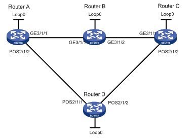
|
Device |
Interface |
IP address |
Device |
Interface |
IP address |
|
Router A |
Loop0 |
1.1.1.9/32 |
Router D |
Loop0 |
4.4.4.9/32 |
|
|
GE 3/1/1 |
10.1.1.1/24 |
|
POS 2/1/1 |
30.1.1.2/24 |
|
|
POS 2/1/2 |
30.1.1.1/24 |
|
POS 2/1/2 |
40.1.1.1/24 |
|
Router B |
Loop0 |
2.2.2.9/32 |
Router C |
Loop0 |
3.3.3.9/32 |
|
|
GE 3/1/1 |
10.1.1.2/24 |
|
GE 3/1/1 |
20.1.1.2/24 |
|
|
GE 3/1/2 |
20.1.1.1/24 |
|
POS 2/1/2 |
40.1.1.2/24 |
Configuration procedure
1. Assign IP addresses and masks to interfaces (see Figure 16)
Details not shown
2. Configure the IGP protocol
# Enable IS-IS to advertise host routes with LSR IDs as destinations on each node. (Details not shown)
Perform the display ip routing-table command on each router. You should see that all nodes learnt the host routes of other nodes with LSR IDs as destinations.
3. Configure MPLS TE basic capabilities, and enable RSVP-TE and CSPF
<RouterA> system-view
[RouterA] mpls lsr-id 1.1.1.9
[RouterA] mpls
[RouterA-mpls] mpls te
[RouterA-mpls] mpls rsvp-te
[RouterA-mpls] mpls te cspf
[RouterA-mpls] quit
[RouterA] interface GigabitEthernet 3/1/1
[RouterA-GigabitEthernet3/1/1] mpls
[RouterA-GigabitEthernet3/1/1] mpls te
[RouterA-GigabitEthernet3/1/1] mpls rsvp-te
[RouterA-GigabitEthernet3/1/1] quit
[RouterA] interface pos 2/1/2
[RouterA-POS2/1/2] mpls
[RouterA-POS2/1/2] mpls te
[RouterA-POS2/1/2] mpls rsvp-te
[RouterA-POS2/1/2] quit
|
|
NOTE: · Follow the same steps to configure Router B, Router C, and Router D. · You need to configure the clock mode of the POS interface on Router D as master clock. |
4. Create an MPLS TE tunnel on Router A
# Configure the MPLS TE tunnel carried on the primary LSP.
[RouterA] interface tunnel 4
[RouterA-Tunnel4] ip address 9.1.1.1 255.255.255.0
[RouterA-Tunnel4] tunnel-protocol mpls te
[RouterA-Tunnel4] destination 3.3.3.9
[RouterA-Tunnel4] mpls te tunnel-id 10
# Enable hot LSP backup.
[RouterA-Tunnel4] mpls te backup hot-standby
[RouterA-Tunnel4] mpls te commit
[RouterA-Tunnel4] quit
# Perform the display interface tunnel command on Router A. You can find that Tunnel 4 is up.
[RouterA] display interface tunnel
Tunnel4 current state: UP
Line protocol current state: UP
Description: Tunnel4 Interface
The Maximum Transmit Unit is 1500
Internet Address is 9.1.1.1/24 Primary
Encapsulation is TUNNEL, service-loopback-group ID not set
Tunnel source unknown, destination 3.3.3.9
Tunnel protocol/transport CR_LSP
Output queue : (Urgent queuing : Size/Length/Discards) 0/100/0
Output queue : (Protocol queuing : Size/Length/Discards) 0/500/0
Output queue : (FIFO queuing : Size/Length/Discards) 0/75/0
Last 300 seconds input: 0 bytes/sec, 0 packets/sec
Last 300 seconds output: 0 bytes/sec, 0 packets/sec
0 packets input, 0 bytes
0 input error
0 packets output, 0 bytes
0 output error
5. Verify the configuration
# Perform the display mpls te tunnel command on Router A. You can find that two tunnels are present with the outgoing interface being GigabitEthernet 3/1/1 and POS 2/1/2 respectively. This indicates that a backup CR-LSP was created upon creation of the primary CR-LSP.
[RouterA] display mpls te tunnel
LSP-Id Destination In/Out-If Name
1.1.1.9:6 3.3.3.9 -/GE3/1/1 Tunnel4
1.1.1.9:2054 3.3.3.9 -/POS2/1/2 Tunnel4
# Perform the display mpls te tunnel path command on Router A to identify the paths that the two tunnels traverse:
[RouterA] display mpls te tunnel path
Tunnel Interface Name : Tunnel4
Lsp ID : 1.1.1.9 :6
Hop Information
Hop 0 10.1.1.1
Hop 1 10.1.1.2
Hop 2 2.2.2.9
Hop 3 20.1.1.1
Hop 4 20.1.1.2
Hop 5 3.3.3.9
Tunnel Interface Name : Tunnel4
Lsp ID : 1.1.1.9 :2054
Hop Information
Hop 0 30.1.1.1
Hop 1 30.1.1.2
Hop 2 4.4.4.9
Hop 3 40.1.1.1
Hop 4 40.1.1.2
Hop 5 3.3.3.9
# Perform the tracert command to draw the picture of the path that a packet must travel to reach the tunnel destination.
[RouterA] tracert –a 1.1.1.9 3.3.3.9
traceroute to 3.3.3.9(3.3.3.9) 30 hops max,40 bytes packet
1 10.1.1.2 25 ms 30.1.1.2 25 ms 10.1.1.2 25 ms
2 40.1.1.2 45 ms 20.1.1.2 29 ms 40.1.1.2 54 ms
The sample output shows that the current LSP traverses Route B but not Router D.
# Shut down interface GigabitEthernet 3/1/2 on Router B. Perform the tracert command on Router A to draw the path to the tunnel destination. You can see that the LSP is re-routed to traverse Router D:
[RouterA] tracert –a 1.1.1.9 3.3.3.9
traceroute to 3.3.3.9(3.3.3.9) 30 hops max,40 bytes packet
1 30.1.1.2 28 ms 27 ms 23 ms
2 40.1.1.2 50 ms 50 ms 49 ms
# Perform the display mpls te tunnel command on Router A. You can find that only the tunnel traversing Router D is present:
[RouterA] display mpls te tunnel
LSP-Id Destination In/Out-If Name
1.1.1.9:2054 3.3.3.9 -/POS2/1/2 Tunnel4
|
|
NOTE: Configuring ordinary CR-LSP backup is almost the same as configuring hot CR-LSP backup except that you need to replace the mpls te backup hot-standby command with the mpls te backup ordinary command. Unlike in hot CR-LSP backup where a secondary tunnel is created immediately upon creation of a primary tunnel, in ordinary CR-LSP backup, a secondary CR-LSP is created only after the primary LSP goes down. |
6. Create a static route for routing MPLS TE tunnel traffic
[RouterA] ip route-static 20.1.1.2 24 tunnel 4 preference 1
Perform the display ip routing-table command on Router A. You can find a static route entry with interface Tunnel4 as the outgoing interface.
FRR configuration example
Network requirements
On a primary LSP Router A → Router B → Router C → Router D, use FRR to protect the link Router B → Router C.
Do the following:
· Create a bypass LSP that traverses the path Router B → Router E → Router C. Router B is the PLR and Router C is the MP.
· Explicitly route the primary TE tunnel and the bypass TE tunnel with the signaling protocol being RSVP-TE.
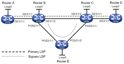
|
Device |
Interface |
IP address |
Device |
Interface |
IP address |
|
Router A |
Loop0 |
1.1.1.1/32 |
Router E |
Loop0 |
5.5.5.5/32 |
|
|
GE 3/1/1 |
2.1.1.1/24 |
|
POS 2/1/1 |
3.2.1.2/24 |
|
Router B |
Loop0 |
2.2.2.2/32 |
|
POS 2/1/2 |
3.3.1.1/24 |
|
|
GE 3/1/1 |
2.1.1.2/24 |
Router C |
Loop0 |
3.3.3.3/32 |
|
|
GE 3/1/2 |
3.1.1.1/24 |
|
GE 3/1/1 |
4.1.1.1/24 |
|
|
POS 2/1/1 |
3.2.1.1/24 |
|
GE 3/1/2 |
3.1.1.2/24 |
|
Router D |
Loop0 |
4.4.4.4/32 |
|
POS 2/1/1 |
3.3.1.2/24 |
|
|
GE 3/1/1 |
4.1.1.2/24 |
|
|
|
Configuration procedure
1. Assign IP addresses and masks to interfaces (see Figure 17)
Details not shown
2. Configure the IGP protocol
# Enable IS-IS to advertise host routes with LSR IDs as destinations on each node. (Details not shown)
# Perform the display ip routing-table command on each router. You should see that all nodes learnt the host routes of other nodes with LSR IDs as destinations. Take Router A for example:
<RouterA> display ip routing-table
Routing Tables: Public
Destinations : 13 Routes : 13
Destination/Mask Proto Pre Cost NextHop Interface
1.1.1.1/32 Direct 0 0 127.0.0.1 InLoop0
2.1.1.0/24 Direct 0 0 2.1.1.1 GE3/1/1
2.1.1.1/32 Direct 0 0 127.0.0.1 InLoop0
2.2.2.2/32 ISIS 15 10 2.1.1.2 GE3/1/1
3.1.1.0/24 ISIS 15 20 2.1.1.2 GE3/1/1
3.2.1.0/24 ISIS 15 20 2.1.1.2 GE3/1/1
3.3.1.0/24 ISIS 15 30 2.1.1.2 GE3/1/1
3.3.3.3/32 ISIS 15 20 2.1.1.2 GE3/1/1
4.1.1.0/24 ISIS 15 30 2.1.1.2 GE3/1/1
4.4.4.4/32 ISIS 15 30 2.1.1.2 GE3/1/1
5.5.5.5/32 ISIS 15 20 2.1.1.2 GE3/1/1
127.0.0.0/8 Direct 0 0 127.0.0.1 InLoop0
127.0.0.1/32 Direct 0 0 127.0.0.1 InLoop0
3. Configure MPLS TE basic capabilities, and enable RSVP-TE and CSPF
# Configure Router A.
<RouterA> system-view
[RouterA] mpls lsr-id 1.1.1.1
[RouterA] mpls
[RouterA-mpls] mpls te
[RouterA-mpls] mpls rsvp-te
[RouterA-mpls] mpls te cspf
[RouterA-mpls] quit
[RouterA] interface GigabitEthernet 3/1/1
[RouterA-GigabitEthernet3/1/1] mpls
[RouterA-GigabitEthernet3/1/1] mpls te
[RouterA-GigabitEthernet3/1/1] mpls rsvp-te
[RouterA-GigabitEthernet3/1/1] quit
# Configure Router B.
<RouterB> system-view
[RouterB] mpls lsr-id 2.2.2.2
[RouterB] mpls
[RouterB-mpls] mpls te
[RouterB-mpls] mpls rsvp-te
[RouterB-mpls] mpls te cspf
[RouterB-mpls] quit
[RouterB] interface GigabitEthernet 3/1/1
[RouterB-GigabitEthernet3/1/1] mpls
[RouterB-GigabitEthernet3/1/1] mpls te
[RouterB-GigabitEthernet3/1/1] mpls rsvp-te
[RouterB-GigabitEthernet3/1/1] quit
[RouterB] interface GigabitEthernet 3/1/2
[RouterB-GigabitEthernet3/1/2] mpls
[RouterB-GigabitEthernet3/1/2] mpls te
[RouterB-GigabitEthernet3/1/2] mpls rsvp-te
[RouterB-GigabitEthernet3/1/2] quit
[RouterB] interface pos 2/1/1
[RouterB-POS2/1/1] mpls
[RouterB-POS2/1/1] mpls te
[RouterB-POS2/1/1] mpls rsvp-te
[RouterB-POS2/1/1] quit
|
|
NOTE: · Follow the same steps to configure Router C, Router D, and Router E. · You need to configure the clock mode of the POS interface on Router E as master clock. |
4. Create an MPLS TE tunnel on Router A, the headend of the primary LSP
# Create an explicit path for the primary LSP.
[RouterA] explicit-path pri-path
[RouterA-explicit-path-pri-path] next hop 2.1.1.2
[RouterA-explicit-path-pri-path] next hop 3.1.1.2
[RouterA-explicit-path-pri-path] next hop 4.1.1.2
[RouterA-explicit-path-pri-path] next hop 4.4.4.4
[RouterA-explicit-path-pri-path] quit
# Configure the MPLS TE tunnel carried on the primary LSP.
[RouterA] interface tunnel 4
[RouterA-Tunnel4] ip address 10.1.1.1 255.255.255.0
[RouterA-Tunnel4] tunnel-protocol mpls te
[RouterA-Tunnel4] destination 4.4.4.4
[RouterA-Tunnel4] mpls te tunnel-id 10
[RouterA-Tunnel4] mpls te path explicit-path pri-path preference 1
# Enabel FRR.
[RouterA-Tunnel4] mpls te fast-reroute
[RouterA-Tunnel4] mpls te commit
[RouterA-Tunnel4] quit
# Perform the display interface tunnel command on Router A. You can find that Tunnel4 is up.
[RouterA] display interface tunnel
Tunnel4 current state: UP
Line protocol current state: UP
Description: Tunnel4 Interface
The Maximum Transmit Unit is 1500
Internet Address is 10.1.1.1/24 Primary
Encapsulation is TUNNEL, service-loopback-group ID not set
Tunnel source unknown, destination 4.4.4.4
Tunnel protocol/transport CR_LSP
Output queue : (Urgent queuing : Size/Length/Discards) 0/100/0
Output queue : (Protocol queuing : Size/Length/Discards) 0/500/0
Output queue : (FIFO queuing : Size/Length/Discards) 0/75/0
Last 300 seconds input: 0 bytes/sec, 0 packets/sec
Last 300 seconds output: 0 bytes/sec, 0 packets/sec
0 packets input, 0 bytes
0 input error
0 packets output, 0 bytes
0 output error
# Perform the display mpls te tunnel-interface command on Router A to verify the configuration of the tunnel interface.
[RouterA] display mpls te tunnel-interface
Tunnel Name : Tunnel4
Tunnel Desc : Tunnel4 Interface
Tunnel State Desc : CR-LSP is Up
Tunnel Attributes :
LSP ID : 1.1.1.1:1
Session ID : 10
Admin State : UP Oper State : UP
Ingress LSR ID : 1.1.1.1 Egress LSR ID: 4.4.4.4
Signaling Prot : RSVP Resv Style : SE
Class Type : CT0 Tunnel BW : 0 kbps
Reserved BW : 0 kbps
Setup Priority : 7 Hold Priority: 7
Affinity Prop/Mask : 0x0/0x0
Explicit Path Name : pri-path
Tie-Breaking Policy : None
Metric Type : None
Record Route : Enabled Record Label : Enabled
FRR Flag : Enabled BackUpBW Flag: Not Supported
BackUpBW Type : - BackUpBW : -
Route Pinning : Disabled
Retry Limit : 10 Retry Interval: 10 sec
Reopt : Disabled Reopt Freq : -
Back Up Type : None
Back Up LSPID : -
Auto BW : Disabled Auto BW Freq : -
Min BW : - Max BW : -
Current Collected BW: -
Interfaces Protected: -
VPN Bind Type : NONE
VPN Bind Value : -
Car Policy : Disabled
Tunnel Group : Primary
Primary Tunnel : -
Backup Tunnel : -
Group Status : -
Oam Status : -
5. Configure a bypass tunnel on Router B (the PLR)
# Create an explicit path for the bypass LSP.
[RouterB] explicit-path by-path
[RouterB-explicit-path-by-path] next hop 3.2.1.2
[RouterB-explicit-path-by-path] next hop 3.3.1.2
[RouterB-explicit-path-by-path] next hop 3.3.3.3
[RouterB-explicit-path-by-path] quit
# Create the bypass tunnel.
[RouterB] interface tunnel 5
[RouterB-Tunnel5] ip address 11.1.1.1 255.255.255.0
[RouterB-Tunnel5] tunnel-protocol mpls te
[RouterB-Tunnel5] destination 3.3.3.3
[RouterB-Tunnel5] mpls te tunnel-id 15
[RouterB-Tunnel5] mpls te path explicit-path by-path preference 1
# Configure the bandwidth that the bypass tunnel protects.
[RouterB-Tunnel5] mpls te backup bandwidth 10000
[RouterB-Tunnel5] mpls te commit
[RouterB-Tunnel5] quit
# Bind the bypass tunnel with the protected interface.
[RouterB] interface GigabitEthernet 3/1/2
[RouterB-GigabitEthernet3/1/2] mpls te fast-reroute bypass-tunnel tunnel 5
[RouterB-GigabitEthernet3/1/2] quit
# Perform the display interface tunnel command on Router B. You can find that Tunnel5 is up.
# Perform the display mpls lsp command on each router. You can find that two LSPs are traversing Router B and Router C.
[RouterA] display mpls lsp
------------------------------------------------------------------
LSP Information: RSVP LSP
------------------------------------------------------------------
FEC In/Out Label In/Out IF Vrf Name
4.4.4.4/32 NULL/1024 -/GE3/1/1
[RouterB] display mpls lsp
------------------------------------------------------------------
LSP Information: RSVP LSP
------------------------------------------------------------------
FEC In/Out Label In/Out IF Vrf Name
4.4.4.4/32 1024/1024 GE3/1/1/GE3/1/2
3.3.3.3/32 NULL/1024 -/POS2/1/1
[RouterC] display mpls lsp
------------------------------------------------------------------
LSP Information: RSVP LSP
------------------------------------------------------------------
FEC In/Out Label In/Out IF Vrf Name
4.4.4.4/32 1024/3 GE3/1/2/GE3/1/1
3.3.3.3/32 3/NULL POS2/1/1/-
[RouterD] display mpls lsp
------------------------------------------------------------------
LSP Information: RSVP LSP
------------------------------------------------------------------
FEC In/Out Label In/Out IF Vrf Name
4.4.4.4/32 3/NULL GE3/1/1/-
[RouterE] display mpls lsp
------------------------------------------------------------------
LSP Information: RSVP LSP
------------------------------------------------------------------
FEC In/Out Label In/Out IF Vrf Name
3.3.3.3/32 1024/3 POS2/1/1/POS2/1/2
# Perform the display mpls te tunnel command on each router. You can find that two MPLS TE tunnels are traversing Router B and Router C.
[RouterA] display mpls te tunnel
LSP-Id Destination In/Out-If Name
1.1.1.1:1 4.4.4.4 -/GE3/1/1 Tunnel4
[RouterB] display mpls te tunnel
LSP-Id Destination In/Out-If Name
1.1.1.1:1 4.4.4.4 GE3/1/1/GE3/1/2 Tunnel4
2.2.2.2:1 3.3.3.3 -/POS2/1/1 Tunnel5
[RouterC] display mpls te tunnel
LSP-Id Destination In/Out-If Name
1.1.1.1:1 4.4.4.4 GE3/1/2/GE3/1/1 Tunnel4
2.2.2.2:1 3.3.3.3 POS2/1/1/- Tunnel5
[RouterD] display mpls te tunnel
LSP-Id Destination In/Out-If Name
1.1.1.1:1 4.4.4.4 GE3/1/1/- Tunnel4
[RouterE] display mpls te tunnel
LSP-Id Destination In/Out-If Name
2.2.2.2:1 3.3.3.3 POS2/1/1/POS2/1/2 Tunnel5
# Perform the display mpls lsp verbose command on Router B. You can find that the bypass tunnel is bound with the protected interface GigabitEthernet 3/1/2 and is currently unused.
[RouterB] display mpls lsp verbose
-------------------------------------------------------------------
LSP Information: RSVP LSP
-------------------------------------------------------------------
No : 1
IngressLsrID : 1.1.1.1
LocalLspID : 1
Tunnel-Interface : Tunnel4
Fec : 4.4.4.4/32
Nexthop : 3.1.1.2
In-Label : 1024
Out-Label : 1024
In-Interface : GigabitEthernet3/1/1
Out-Interface : GigabitEthernet3/1/2
LspIndex : 4097
Tunnel ID : 0x22001
LsrType : Transit
Bypass In Use : Not Used
BypassTunnel : Tunnel Index[Tunnel5], InnerLabel[1024]
Mpls-Mtu : 1500
No : 2
IngressLsrID : 2.2.2.2
LocalLspID : 1
Tunnel-Interface : Tunnel5
Fec : 3.3.3.3/32
Nexthop : 3.2.1.2
In-Label : NULL
Out-Label : 1024
In-Interface : ----------
Out-Interface : POS2/1/1
LspIndex : 4098
Tunnel ID : 0x22002
LsrType : Ingress
Bypass In Use : Not Exists
BypassTunnel : Tunnel Index[---]
Mpls-Mtu : 1500
6. Verify the FRR function
# Shut down the protected outgoing interface on PLR.
[RouterB] interface GigabitEthernet 3/1/2
[RouterB-GigabitEthernet3/1/2] shutdown
%Sep 7 08:53:34 2004 RouterB IFNET/5/UPDOWN:Line protocol on the interface GigabitEthernet3/1/2 turns into DOWN state
# Perform the display interface tunnel 4 command on Router A to identify the state of the primary LSP. You can find that the tunnel interface is still up.
# Perform the display mpls te tunnel-interface command on Router A to verify the configuration of the tunnel interface.
[RouterA] display mpls te tunnel-interface
Tunnel Name : Tunnel4
Tunnel Desc : Tunnel4 Interface
Tunnel State Desc : Modifying CR-LSP is setting up
Tunnel Attributes :
LSP ID : 1.1.1.1:1
Session ID : 10
Admin State : UP Oper State : UP
Ingress LSR ID : 1.1.1.1 Egress LSR ID: 4.4.4.4
Signaling Prot : RSVP Resv Style : SE
Class Type : CT0 Tunnel BW : 0 kbps
Reserved BW : 0 kbps
Setup Priority : 7 Hold Priority: 7
Affinity Prop/Mask : 0/0
Explicit Path Name : pri-path
Tie-Breaking Policy : None
Metric Type : None
Record Route : Enabled Record Label : Enabled
FRR Flag : Enabled BackUpBW Flag: Not Supported
BackUpBW Type : - BackUpBW : -
Route Pinning : Disabled
Retry Limit : 10 Retry Interval: 10 sec
Reopt : Disabled Reopt Freq : -
Back Up Type : None
Back Up LSPID : -
Auto BW : Disabled Auto BW Freq : -
Min BW : - Max BW : -
Current Collected BW: -
Interfaces Protected: -
VPN Bind Type : NONE
VPN Bind Value : -
Car Policy : Disabled
Tunnel Group : Primary
Primary Tunnel : -
Backup Tunnel : -
Group Status : -
Oam Status : -
Tunnel Name : Tunnel4
Tunnel Desc : Tunnel4 Interface
Tunnel State Desc : Modifying CR-LSP is setting up
Tunnel Attributes :
LSP ID : 1.1.1.1:1025
Session ID : 10
Admin State : Oper State : Modified
Ingress LSR ID : 1.1.1.1 Egress LSR ID: 4.4.4.4
Signaling Prot : RSVP Resv Style : SE
Class Type : CT0 Tunnel BW : 0 kbps
Reserved BW : 0 kbps
Setup Priority : 7 Hold Priority: 7
Affinity Prop/Mask : 0/0
Explicit Path Name : pri-path
Tie-Breaking Policy : None
Metric Type : None
Record Route : Enabled Record Label : Enabled
FRR Flag : Enabled BackUpBW Flag: Not Supported
BackUpBW Type : - BackUpBW : -
Route Pinning : Disabled
Retry Limit : 10 Retry Interval: 10 sec
Reopt : Disabled Reopt Freq : -
Back Up Type : None
Back Up LSPID : -
Auto BW : Disabled Auto BW Freq : -
Min BW : - Max BW : -
Current Collected BW: -
Interfaces Protected: -
VPN Bind Type : NONE
VPN Bind Value : -
Car Policy : Disabled
Tunnel Group : Primary
Primary Tunnel : -
Backup Tunnel : -
Group Status : -
Oam Status : -
|
|
NOTE: If you perform the display mpls te tunnel-interface command immediately after an FRR protection switch, you are likely to see two CR-LSPs in up state are present. This is normal because the make-before-break mechanism of FRR introduces a delay before removing the old LSP after a new LSP is created. |
# Perform the display mpls lsp verbose command on Router B. You can find that the bypass tunnel is in use.
[RouterB] display mpls lsp verbose
------------------------------------------------------------------
LSP Information: RSVP LSP
------------------------------------------------------------------
No : 1
IngressLsrID : 1.1.1.1
LocalLspID : 1
Tunnel-Interface : Tunnel4
Fec : 4.4.4.4/32
Nexthop : 3.1.1.2
In-Label : 1024
Out-Label : 1024
In-Interface : GigabitEthernet3/1/1
Out-Interface : GigabitEthernet3/1/2
LspIndex : 4097
Tunnel ID : 0x22001
LsrType : Transit
Bypass In Use : In Use
BypassTunnel : Tunnel Index[Tunnel5], InnerLabel[1024]
No : 2
IngressLsrID : 2.2.2.2
LocalLspID : 1
Tunnel-Interface : Tunnel5
Fec : 3.3.3.3/32
Nexthop : 3.2.1.2
In-Label : NULL
Out-Label : 1024
In-Interface : ----------
Out-Interface : POS2/1/1
LspIndex : 4098
Tunnel ID : 0x22002
LsrType : Ingress
Bypass In Use : Not Exists
BypassTunnel : Tunnel Index[---]
# Set the FRR polling timer to five seconds on PLR.
[RouterB] mpls
[RouterB-mpls] mpls te timer fast-reroute 5
[RouterB-mpls] quit
# Bring the protected outgoing interface up on PLR.
[RouterB] interface GigabitEthernet 3/1/2
[RouterB-GigabitEthernet3/1/2] undo shutdown
%Sep 7 09:01:31 2004 RouterB IFNET/5/UPDOWN:Line protocol on the interface GigabitEthernet3/1/2 turns into UP state
# Perform the display interface tunnel command on Router A to identify the state of the primary LSP. You can find that the tunnel interface is up.
# About 5 seconds later, perform the display mpls lsp verbose command on Router B. You can find that Tunnel5 is still bound with interface GigabitEthernet 3/1/2 and is unused.
7. Create a static route for routing MPLS TE tunnel traffic
[RouterA] ip route-static 4.1.1.2 24 tunnel 4 preference 1
Perform the display ip routing-table command on Router A. You can find a static route entry with interface Tunnel4 as the outgoing interface.
IETF DS-TE configuration example
Network requirements
Router A, Router B, Router C, and Router D are running IS-IS and all of them are Level-2 routers.
Use RSVP-TE to create a TE tunnel from Router A to Router D. Traffic of the tunnel belongs to CT 2, and the tunnel needs a bandwidth of 4000 kbps.
For each link that the tunnel traverses, the maximum bandwidth is 10000 kbps, the maximum reservable bandwidth is 10000 kbps, and BC 1, BC 2, and BC 3 are 8000 kbps, 5000 kbps, and 3000 kbps respectively.
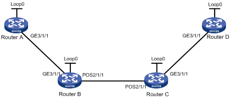
|
Device |
Interface |
IP address |
Device |
Interface |
IP address |
|
Router A |
Loop0 |
1.1.1.9/32 |
Router C |
Loop0 |
3.3.3.9/32 |
|
|
GE3/1/1 |
10.1.1.1/24 |
|
GE3/1/1 |
30.1.1.1/24 |
|
Router B |
Loop0 |
2.2.2.9/32 |
|
POS2/1/1 |
20.1.1.2/24 |
|
|
GE3/1/1 |
10.1.1.2/24 |
Router D |
Loop0 |
4.4.4.9/32 |
|
|
POS2/1/1 |
20.1.1.1/24 |
|
GE3/1/1 |
30.1.1.2/24 |
Configuration procedure
1. Configure IP addresses for interfaces.
Assign IP addresses and masks to interfaces (see Figure 18, details not shown).
2. Configure IS-IS, and advertise host routes with LSR IDs as destinations.
# Configurations on Router A.
<RouterA> system-view
[RouterA] isis 1
[RouterA-isis-1] network-entity 00.0005.0000.0000.0001.00
[RouterA-isis-1] quit
[RouterA] interface GigabitEthernet 3/1/1
[RouterA-GigabitEthernet3/1/1] isis enable 1
[RouterA-GigabitEthernet3/1/1] isis circuit-level level-2
[RouterA-GigabitEthernet3/1/1] quit
[RouterA] interface loopback 0
[RouterA-LoopBack0] isis enable 1
[RouterA-LoopBack0] isis circuit-level level-2
[RouterA-LoopBack0] quit
# Configurations on Router B.
<RouterB> system-view
[RouterB] isis 1
[RouterB-isis-1] network-entity 00.0005.0000.0000.0002.00
[RouterB-isis-1] quit
[RouterB] interface GigabitEthernet 3/1/1
[RouterB-GigabitEthernet3/1/1] isis enable 1
[RouterB-GigabitEthernet3/1/1] isis circuit-level level-2
[RouterB-GigabitEthernet3/1/1] quit
[RouterB] interface POS 2/1/1
[RouterB-POS2/1/1] isis enable 1
[RouterB-POS2/1/1] isis circuit-level level-2
[RouterB-POS2/1/1] quit
[RouterB] interface loopback 0
[RouterB-LoopBack0] isis enable 1
[RouterB-LoopBack0] isis circuit-level level-2
[RouterB-LoopBack0] quit
# Configurations on Router C.
<RouterC> system-view
[RouterC] isis 1
[RouterC-isis-1] network-entity 00.0005.0000.0000.0003.00
[RouterC-isis-1] quit
[RouterC] interface GigabitEthernet 3/1/1
[RouterC-GigabitEthernet3/1/1] isis enable 1
[RouterC-GigabitEthernet3/1/1] isis circuit-level level-2
[RouterC-GigabitEthernet3/1/1] quit
[RouterC] interface POS 2/1/1
[RouterC-POS2/1/1] isis enable 1
[RouterC-POS2/1/1] isis circuit-level level-2
[RouterC-POS2/1/1] quit
[RouterC] interface loopback 0
[RouterC-LoopBack0] isis enable 1
[RouterC-LoopBack0] isis circuit-level level-2
[RouterC-LoopBack0] quit
# Configurations on Router D.
<RouterD> system-view
[RouterD] isis 1
[RouterD-isis-1] network-entity 00.0005.0000.0000.0004.00
[RouterD-isis-1] quit
[RouterD] interface GigabitEthernet 3/1/1
[RouterD-GigabitEthernet3/1/1] isis enable 1
[RouterD-GigabitEthernet3/1/1] isis circuit-level level-2
[RouterD-GigabitEthernet3/1/1] quit
[RouterD] interface loopback 0
[RouterD-LoopBack0] isis enable 1
[RouterD-LoopBack0] isis circuit-level level-2
[RouterD-LoopBack0] quit
# Execute the display ip routing-table command on each router. You see that each router has learnt the routes to the LSR IDs of the other routers. Take Router A for example:
[RouterA] display ip routing-table
Routing Tables: Public
Destinations : 10 Routes : 10
Destination/Mask Proto Pre Cost NextHop Interface
1.1.1.9/32 Direct 0 0 127.0.0.1 InLoop0
2.2.2.9/32 ISIS 15 10 10.1.1.2 GE3/1/1
3.3.3.9/32 ISIS 15 20 10.1.1.2 GE3/1/1
4.4.4.9/32 ISIS 15 30 10.1.1.2 GE3/1/1
10.1.1.0/24 Direct 0 0 10.1.1.1 GE3/1/1
10.1.1.1/32 Direct 0 0 127.0.0.1 InLoop0
20.1.1.0/24 ISIS 15 20 10.1.1.2 GE3/1/1
30.1.1.0/24 ISIS 15 30 10.1.1.2 GE3/1/1
127.0.0.0/8 Direct 0 0 127.0.0.1 InLoop0
127.0.0.1/32 Direct 0 0 127.0.0.1 InLoop0
3. Configure MPLS TE basic capabilities, enable RSVP-TE and CSPF, and configure the DS-TE mode as IETF.
# Configure Router A.
[RouterA] mpls lsr-id 1.1.1.9
[RouterA] mpls
[RouterA-mpls] mpls te
[RouterA-mpls] mpls rsvp-te
[RouterA-mpls] mpls te cspf
[RouterA-mpls] mpls te ds-te mode ietf
[RouterA-mpls] quit
[RouterA] interface GigabitEthernet 3/1/1
[RouterA-GigabitEthernet3/1/1] mpls
[RouterA-GigabitEthernet3/1/1] mpls te
[RouterA-GigabitEthernet3/1/1] mpls rsvp-te
[RouterA-GigabitEthernet3/1/1] quit
# Configure Router B.
[RouterB] mpls lsr-id 2.2.2.9
[RouterB] mpls
[RouterB-mpls] mpls te
[RouterB-mpls] mpls rsvp-te
[RouterB-mpls] mpls te cspf
[RouterB-mpls] mpls te ds-te mode ietf
[RouterB-mpls] quit
[RouterB] interface GigabitEthernet 3/1/1
[RouterB-GigabitEthernet3/1/1] mpls
[RouterB-GigabitEthernet3/1/1] mpls te
[RouterB-GigabitEthernet3/1/1] mpls rsvp-te
[RouterB-GigabitEthernet3/1/1] quit
[RouterB] interface POS 2/1/1
[RouterB-POS2/1/1] mpls
[RouterB-POS2/1/1] mpls te
[RouterB-POS2/1/1] mpls rsvp-te
[RouterB-POS2/1/1] quit
# Configure Router C.
[RouterC] mpls lsr-id 3.3.3.9
[RouterC] mpls
[RouterC-mpls] mpls te
[RouterC-mpls] mpls rsvp-te
[RouterC-mpls] mpls te cspf
[RouterC-mpls] mpls te ds-te mode ietf
[RouterC-mpls] quit
[RouterC] interface GigabitEthernet 3/1/1
[RouterC-GigabitEthernet3/1/1] mpls
[RouterC-GigabitEthernet3/1/1] mpls te
[RouterC-GigabitEthernet3/1/1] mpls rsvp-te
[RouterC-GigabitEthernet3/1/1] quit
[RouterC] interface POS 2/1/1
[RouterC-POS2/1/1] mpls
[RouterC-POS2/1/1] mpls te
[RouterC-POS2/1/1] mpls rsvp-te
[RouterC-POS2/1/1] quit
# Configure Router D.
[RouterD] mpls lsr-id 4.4.4.9
[RouterD] mpls
[RouterD-mpls] mpls te
[RouterD-mpls] mpls rsvp-te
[RouterD-mpls] mpls te cspf
[RouterD-mpls] mpls te ds-te mode ietf
[RouterD-mpls] quit
[RouterD] interface GigabitEthernet 3/1/1
[RouterD-GigabitEthernet3/1/1] mpls
[RouterD-GigabitEthernet3/1/1] mpls te
[RouterD-GigabitEthernet3/1/1] mpls rsvp-te
[RouterD-GigabitEthernet3/1/1] quit
4. Configure IS-IS TE
# Configure Router A.
[RouterA] isis 1
[RouterA-isis-1] cost-style wide
[RouterA-isis-1] traffic-eng level-2
[RouterA-isis-1] quit
# Configure Router B.
[RouterB] isis 1
[RouterB-isis-1] cost-style wide
[RouterB-isis-1] traffic-eng level-2
[RouterB-isis-1] quit
# Configure Router C.
[RouterC] isis 1
[RouterC-isis-1] cost-style wide
[RouterC-isis-1] traffic-eng level-2
[RouterC-isis-1] quit
# Configure Router D,
[RouterD] isis 1
[RouterD-isis-1] cost-style wide
[RouterD-isis-1] traffic-eng level-2
[RouterD-isis-1] quit
5. Configure MPLS TE attributes of links
# Configure the maximum bandwidth and bandwidth constraints on Router A.
[RouterA] interface GigabitEthernet 3/1/1
[RouterA-GigabitEthernet3/1/1] mpls te max-link-bandwidth 10000
[RouterA-GigabitEthernet3/1/1] mpls te max-reservable-bandwidth rdm 10000 bc1 8000 bc2 5000 bc3 2000
[RouterA-GigabitEthernet3/1/1] quit
# Configure the maximum bandwidth and bandwidth constraints on Router B.
[RouterB] interface GigabitEthernet 3/1/1
[RouterB-GigabitEthernet3/1/1] mpls te max-link-bandwidth 10000
[RouterB-GigabitEthernet3/1/1] mpls te max-reservable-bandwidth rdm 10000 bc1 8000 bc2 5000 bc3 2000
[RouterB-GigabitEthernet3/1/1] quit
[RouterB] interface POS 2/1/1
[RouterB-POS2/1/1] mpls te max-link-bandwidth 10000
[RouterB-POS2/1/1] mpls te max-reservable-bandwidth rdm 10000 bc1 8000 bc2 5000 bc3 2000
[RouterB-POS2/1/1] quit
# Configure the maximum bandwidth and bandwidth constraints on Router C.
[RouterC] interface GigabitEthernet 3/1/1
[RouterC-GigabitEthernet3/1/1] mpls te max-link-bandwidth 10000
[RouterC-GigabitEthernet3/1/1] mpls te max-reservable-bandwidth rdm 10000 bc1 8000 bc2 5000 bc3 2000
[RouterC-GigabitEthernet3/1/1] quit
[RouterC] interface POS 2/1/1
[RouterC-POS2/1/1] mpls te max-link-bandwidth 10000
[RouterC-POS2/1/1] mpls te max-reservable-bandwidth rdm 10000 bc1 8000 bc2 5000 bc3 2000
[RouterC-POS2/1/1] quit
# Configure the maximum bandwidth and bandwidth constraints on Router D.
[RouterD] interface GigabitEthernet 3/1/1
[RouterD-GigabitEthernet3/1/1] mpls te max-link-bandwidth 10000
[RouterD-GigabitEthernet3/1/1] mpls te max-reservable-bandwidth rdm 10000 bc1 8000 bc2 5000 bc3 2000
[RouterD-GigabitEthernet3/1/1] quit
6. Create an MPLS TE tunnel
# Create an MPLS TE tunnel on Router A.
[RouterA] interface tunnel 1
[RouterA-Tunnel1] ip address 7.1.1.1 255.255.255.0
[RouterA-Tunnel1] tunnel-protocol mpls te
[RouterA-Tunnel1] destination 4.4.4.9
[RouterA-Tunnel1] mpls te tunnel-id 10
[RouterA-Tunnel1] mpls te signal-protocol rsvp-te
[RouterA-Tunnel1] mpls te bandwidth ct2 4000
[RouterA-Tunnel1] mpls te priority 0
[RouterA-Tunnel1] mpls te commit
[RouterA-Tunnel1] quit
7. Verify the configuration
# Execute the display interface tunnel command on Router A. You see that the tunnel interface is up.
[RouterA] display interface tunnel
Tunnel1 current state: UP
Line protocol current state: UP
Description: Tunnel1 Interface
The Maximum Transmit Unit is 64000
Internet Address is 7.1.1.1/24 Primary
Encapsulation is TUNNEL, service-loopback-group ID not set
Tunnel source unknown, destination 4.4.4.9
Tunnel protocol/transport CR_LSP
Output queue : (Urgent queuing : Size/Length/Discards) 0/100/0
Output queue : (Protocol queuing : Size/Length/Discards) 0/500/0
Output queue : (FIFO queuing : Size/Length/Discards) 0/75/0
Last 300 seconds input: 0 bytes/sec, 0 packets/sec
Last 300 seconds output: 0 bytes/sec, 0 packets/sec
0 packets input, 0 bytes
0 input error
0 packets output, 0 bytes
0 output error
# Execute the display mpls te tunnel-interface command on Router A to view the detailed information of the tunnel.
[RouterA] display mpls te tunnel-interface
Tunnel Name : Tunnel1
Tunnel Desc : Tunnel1 Interface
Tunnel State Desc : CR-LSP is Up
Tunnel Attributes :
LSP ID : 1.1.1.9:3
Session ID : 10
Admin State : UP Oper State : UP
Ingress LSR ID : 1.1.1.9 Egress LSR ID: 4.4.4.9
Signaling Prot : RSVP Resv Style : SE
Class Type : CT2 Tunnel BW : 4000 kbps
Reserved BW : 4000 kbps
Setup Priority : 0 Hold Priority: 0
Affinity Prop/Mask : 0x0/0x0
Explicit Path Name : -
Tie-Breaking Policy : None
Metric Type : None
Record Route : Disabled Record Label : Disabled
FRR Flag : Disabled BackUpBW Flag: Not Supported
BackUpBW Type : - BackUpBW : -
Route Pinning : Disabled
Retry Limit : 10 Retry Interval: 10 sec
Reopt : Disabled Reopt Freq : -
Back Up Type : None
Back Up LSPID : -
Auto BW : Disabled Auto BW Freq : -
Min BW : - Max BW : -
Current Collected BW: -
Interfaces Protected: -
VPN Bind Type : NONE
VPN Bind Value : -
Car Policy : Disabled
Tunnel Group : Primary
Primary Tunnel : -
Backup Tunnel : -
Group Status : -
Oam Status : -
# Execute the display mpls te cspf tedb all command on Router A to view the link information in the TEDB.
[RouterA] display mpls te cspf tedb all
Maximum Node Supported: 128 Maximum Link Supported: 256
Current Total Node Number: 4 Current Total Link Number: 6
Id MPLS LSR-Id IGP Process-Id Area Link-Count
1 3.3.3.9 ISIS 1 Level-2 2
2 2.2.2.9 ISIS 1 Level-2 2
3 4.4.4.9 ISIS 1 Level-2 1
4 1.1.1.9 ISIS 1 Level-2 1
# Execute the display mpls te link-administration bandwidth-allocation command on Router A to view interface bandwidth information.
[RouterA] display mpls te link-administration bandwidth-allocation interface GigabitEthernet 3/1/1
Link ID: GigabitEthernet 3/1/1
Max Link Bandwidth : 10000 kbits/sec
Max Reservable Bandwidth PreStandard RDM : 0 kbits/sec
Max Reservable Bandwidth IETF RDM : 10000 kbits/sec
Max Reservable Bandwidth IETF MAM : 0 kbits/sec
Downstream LSP Count : 1
UpStream LSP Count : 1
Downstream Bandwidth : 4000 kbits/sec
Upstream Bandwidth : 0 kbits/sec
IPUpdown Link Status : UP
PhysicalUpdown Link Status : UP
BC PreStandard Mode RDM(kbps) IETF Mode RDM(kbps) IETF Mode MAM(kbps)
0 0 10000 0
1 0 8000 0
2 0 5000 0
3 0 2000 0
TE CLASS CLASS TYPE PRIORITY BW RESERVED(kbps) BW AVAILABLE(kbps)
0 0 7 0 6000
1 1 7 0 4000
2 2 7 0 1000
3 3 7 0 1000
4 0 0 0 6000
5 1 0 0 4000
6 2 0 4000 1000
7 3 0 0 1000
8. Create a static route to import traffic into the MPLS TE tunnel
[RouterA] ip route-static 30.1.1.2 24 tunnel 1 preference 1
Execute the display ip routing-table command on Router A. There is a static route entry with interface Tunnel1 as the outgoing interface.
MPLS LDP over MPLS TE configuration example
Network requirements
Router A through Router E all support MPLS and run OSPF as the IGP.
A local LDP session is established between Router A and Router B, as well as between Router C and Router D. A remote LDP session is established between Router B and Router C. An MPLS TE tunnel is established along Router B → Router E → Router C by using RSVP-TE.
Router B uses the SPE card to process MPLS L2VPN services.
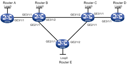
|
Device |
Interface |
IP address |
Device |
Interface |
IP address |
|
Router A |
Loop0 |
1.1.1.1/32 |
Router E |
Loop0 |
5.5.5.5/32 |
|
|
GE3/1/1 |
2.1.1.1/24 |
|
GE2/1/1 |
3.2.1.2/24 |
|
Router B |
Loop0 |
2.2.2.2/32 |
|
GE2/1/2 |
3.3.1.1/24 |
|
|
GE3/1/1 |
2.1.1.2/24 |
Router C |
Loop0 |
3.3.3.3/32 |
|
|
GE3/1/2 |
3.1.1.1/24 |
|
GE3/1/1 |
4.1.1.1/24 |
|
|
GE2/1/1 |
3.2.1.1/24 |
|
GE3/1/2 |
3.1.1.2/24 |
|
Router D |
Loop0 |
4.4.4.4/32 |
|
GE2/1/1 |
3.3.1.2/24 |
|
|
GE3/1/1 |
4.1.1.2/24 |
|
|
|
Configuration procedure
1. Assign IP addresses and masks to interfaces (see Figure 19)
Details not shown
2. Configure the IGP protocol
Enable OSPF on each router to advertise subnets to which interfaces belong and the host routes with LSR IDs as destinations. (Details not shown)
3. Configure MPLS LDP basic capabilities on Router A and Router D
Details not shown
4. Configure MPLS TE basic capabilities and enable RSVP-TE and CSPF on Router B, Router C and Router E
# Configure Router B.
<RouterB> system-view
[RouterB] mpls lsr-id 2.2.2.2
[RouterB] mpls
[RouterB-mpls] mpls te
[RouterB-mpls] mpls rsvp-te
[RouterB-mpls] mpls te cspf
[RouterB-mpls] quit
[RouterB] interface GigabitEthernet 2/1/1
[RouterB-GigabitEthernet2/1/1] mpls
[RouterB-GigabitEthernet2/1/1] mpls te
[RouterB-GigabitEthernet2/1/1] mpls rsvp-te
[RouterB-GigabitEthernet2/1/1] quit
# Configure Router E.
<RouterE> system-view
[RouterE] mpls lsr-id 5.5.5.5
[RouterE] mpls
[RouterE-mpls] mpls te
[RouterE-mpls] mpls rsvp-te
[RouterE-mpls] mpls te cspf
[RouterE-mpls] quit
[RouterE] interface GigabitEthernet 2/1/1
[RouterE-GigabitEthernet2/1/1] mpls
[RouterE-GigabitEthernet2/1/1] mpls te
[RouterE-GigabitEthernet2/1/1] mpls rsvp-te
[RouterE-GigabitEthernet2/1/1] quit
[RouterE] interface GigabitEthernet 2/1/2
[RouterE-GigabitEthernet2/1/2] mpls
[RouterE-GigabitEthernet2/1/2] mpls te
[RouterE-GigabitEthernet2/1/2] mpls rsvp-te
[RouterE-GigabitEthernet2/1/2] quit
# Configure Router C.
<RouterC> system-view
[RouterC] mpls lsr-id 3.3.3.3
[RouterC] mpls
[RouterC-mpls] mpls te
[RouterC-mpls] mpls rsvp-te
[RouterC-mpls] mpls te cspf
[RouterC-mpls] quit
[RouterC] interface GigabitEthernet 2/1/1
[RouterC-GigabitEthernet2/1/1] mpls
[RouterC-GigabitEthernet2/1/1] mpls te
[RouterC-GigabitEthernet2/1/1] mpls rsvp-te
[RouterC-GigabitEthernet2/1/1] quit
5. Create an MPLS TE tunnel on Router B
# Configure an MPLS TE tunnel.
[RouterB] interface tunnel 3
[RouterB-Tunnel3] ip address 10.1.1.1 255.255.255.0
[RouterB-Tunnel3] tunnel-protocol mpls te
[RouterB-Tunnel3] destination 3.3.3.3
[RouterB-Tunnel3] mpls te tunnel-id 10
# Configure IGP shortcut.
[RouterB-Tunnel3] mpls te igp shortcut
[RouterB-Tunnel3] mpls te igp metric relative -1
[RouterB-Tunnel3] mpls te commit
# Enable MPLS.
[RouterB-Tunnel3] mpls
[RouterB-Tunnel3] quit
# Configure OSPF TE.
[RouterB] ospf
[RouterB-ospf-1] opaque-capability enable
[RouterB-ospf-1] enable traffic-adjustment
[RouterB-ospf-1] area 0.0.0.0
[RouterB-ospf-1-area-0.0.0.0] mpls-te enable
[RouterB-ospf-1-area-0.0.0.0] quit
[RouterB-ospf-1] quit
After previous configurations, execute the display interface tunnel command on Router B. You can see that tunnel interface Tunnel 3 is up.
[RouterB] display interface tunnel
Tunnel3 current state: UP
Line protocol current state: UP
Description: Tunnel3 Interface
The Maximum Transmit Unit is 1500
Internet Address is 10.1.1.1/24 Primary
Encapsulation is TUNNEL, service-loopback-group ID not set.
Tunnel source unknown, destination 3.3.3.3
Tunnel protocol/transport CR_LSP
Output queue : (Urgent queuing : Size/Length/Discards) 0/100/0
Output queue : (Protocol queuing : Size/Length/Discards) 0/500/0
Output queue : (FIFO queuing : Size/Length/Discards) 0/75/0
Last 300 seconds input: 0 bytes/sec, 0 packets/sec
Last 300 seconds output: 8 bytes/sec, 0 packets/sec
0 packets input, 0 bytes
0 input error
47 packets output, 2740 bytes
0 output error
Execute the display ip routing-table command on Router B. You can see that the outgoing interface to Router C is the tunnel interface Tunnel 3.
[RouterB] display ip routing-table
Routing Tables: Public
Destinations : 12 Routes : 12
Destination/Mask Proto Pre Cost NextHop Interface
1.1.1.1/32 OSPF 10 1 2.1.1.1 GE3/1/1
2.1.1.0/24 Direct 0 0 2.1.1.2 GE3/1/1
2.1.1.2/32 Direct 0 0 127.0.0.1 InLoop0
2.2.2.2/32 Direct 0 0 127.0.0.1 InLoop0
3.1.1.0/24 Direct 0 0 3.1.1.1 GE3/1/2
3.1.1.1/32 Direct 0 0 127.0.0.1 InLoop0
3.3.3.3/32 OSPF 10 1 10.1.1.1 Tunnel3
4.1.1.0/24 OSPF 10 2 10.1.1.1 Tunmel3
127.0.0.0/8 Direct 0 0 127.0.0.1 InLoop0
127.0.0.1/32 Direct 0 0 127.0.0.1 InLoop0
|
|
CAUTION: · You must configure IGP shortcut or a static route for the MPLS TE tunnel, so that IP routing prefers the MPLS TE tunnel interface as the outgoing interface. · You must configure the tunnel tailend LSR ID as the tunnel destination. |
6. Configure LDP on Router B and Router C
# Configure Router B.
[RouterB] mpls
[RouterB-mpls] mpls ldp
[RouterB-mpls] quit
[RouterB] interface GigabitEthernet 3/1/1
[RouterB-GigabitEthernet3/1/1] mpls
[RouterB-GigabitEthernet3/1/1] mpls ldp
[RouterB-GigabitEthernet3/1/1] quit
[RouterB] mpls ldp remote-peer C
[RouterB-mpls-ldp-remote-c] remote-ip 3.3.3.3
[RouterB-mpls-ldp-remote-c] prefix-label advertise
[RouterB-mpls-ldp-remote-c] quit
# Configure Router C.
[RouterC] mpls
[RouterC-mpls] mpls ldp
[RouterC-mpls] quit
[RouterC] interface GigabitEthernet 3/1/1
[RouterC-GigabitEthernet3/1/1] mpls
[RouterC-GigabitEthernet3/1/1] mpls ldp
[RouterC-GigabitEthernet3/1/1] quit
[RouterC] mpls ldp remote-peer b
[RouterC-mpls-ldp-remote-b] remote-ip 2.2.2.2
[RouterC-mpls-ldp-remote-b] prefix-label advertise
[RouterC-mpls-ldp-remote-b] quit
# Execute the display mpls ldp session command on Router B. You can see that a remote session is established between Router B and Router C.
[RouterB] display mpls ldp session verbose
LDP Session(s) in Public Network
----------------------------------------------------------------------
Peer LDP ID : 1.1.1.1:0 Local LDP ID : 2.2.2.2:0
TCP Connection : 2.2.2.2 -> 1.1.1.1
Session State : Operational Session Role : Active
Session FT Flag : Off MD5 Flag : Off
Reconnect Timer : --- Recovery Timer : ---
Negotiated Keepalive Timer : 45 Sec
Keepalive Message Sent/Rcvd : 437/437 (Message Count)
Label Advertisement Mode : Downstream Unsolicited
Label Resource Status(Peer/Local) : Available/Available
Peer Discovery Mechanism : Basic
Session existed time : 000:01:48 (DDD:HH:MM)
LDP Basic Discovery Source : GigabitEthernet3/1/1
Addresses received from peer: (Count: 2)
2.1.1.1 1.1.1.1
----------------------------------------------------------------------
Peer LDP ID : 3.3.3.3:0 Local LDP ID : 2.2.2.2:0
TCP Connection : 2.2.2.2 <- 3.3.3.3
Session State : Operational Session Role : Passive
Session FT Flag : Off MD5 Flag : Off
Reconnect Timer : --- Recovery Timer : ---
Negotiated Keepalive Timer : 45 Sec
Keepalive Message Sent/Rcvd : 411/411 (Message Count)
Label Advertisement Mode : Downstream Unsolicited
Label Resource Status(Peer/Local) : Available/Available
Peer Discovery Mechanism : Extended
Session existed time : 000:01:42 (DDD:HH:MM)
LDP Extended Discovery Source : Remote peer: 1
Addresses received from peer: (Count: 2)
4.1.1.1 3.3.3.3
----------------------------------------------------------------------
# Execute the display mpls ldp lsp command on Router B. You can see that Router C sent label mapping messages to Router B and established an LDP LSP.
[RouterB] display mpls ldp lsp
LDP LSP Information
----------------------------------------------------------------------
SN DestAddress/Mask In/OutLabel Next-Hop In/Out-Interface
----------------------------------------------------------------------
1 1.1.1.1/32 NULL/3 2.1.1.1 -------/GE3/1/1
2 2.2.2.2/32 3/NULL 127.0.0.1 -------/InLoop0
3 3.3.3.3/32 NULL/3 10.1.1.1 -------/Tunnel3
4 3.3.3.3/32 1024/3 10.1.1.1 -------/Tunnel3
----------------------------------------------------------------------
A '*' before an LSP means the LSP is not established
A '*' before a Label means the USCB or DSCB is stale
|
|
CAUTION: The IP address of the LDP remote peer must be configured as the LSR ID of the MPLS TE tunnel tailend. |
7. Verify the configuration
Execute the display mpls lsp command on Rotuer B. You can see that the LDP LSP from Router B to Rotuer C is nested within the MPLS TE tunnel, that is, the outgoing interface of the LDP LSP is the MPLS TE tunnel interface.
[RouterB] display mpls lsp include 3.3.3.3 32 verbose
----------------------------------------------------------------------
LSP Information: RSVP LSP
----------------------------------------------------------------------
No : 1
IngressLsrID : 2.2.2.2
LocalLspID : 1
Tunnel-Interface : Tunnel3
Fec : 3.3.3.3/32
Nexthop : 3.2.1.2
In-Label : NULL
Out-Label : 1024
In-Interface : ----------
Out-Interface : GigabitEthernet 2/1/1
LspIndex : 3073
Tunnel ID : 0x11000c
LsrType : Ingress
Bypass In Use : Not Exists
BypassTunnel : Tunnel Index[---]
----------------------------------------------------------------------
LSP Information: LDP LSP
----------------------------------------------------------------------
No : 2
VrfIndex :
Fec : 3.3.3.3/32
Nexthop : 10.1.1.1
In-Label : NULL
Out-Label : 3
In-Interface : ----------
Out-Interface : Tunnel3
LspIndex : 6147
Tunnel ID : 0x11000e
LsrType : Ingress
Outgoing Tunnel ID : 0x15000d
Label Operation : PUSH
No : 3
VrfIndex :
Fec : 3.3.3.3/32
Nexthop : 10.1.1.1
In-Label : 1024
Out-Label : 3
In-Interface : ----------
Out-Interface : Tunnel3
LspIndex : 6148
Tunnel ID : 0x11000f
LsrType : Transit
Outgoing Tunnel ID : 0x15000d
Label Operation : SWAP
MPLS TE in MPLS L3VPN configuration example
Network requirements
CE 1 and CE 2 belong to VPN 1. They are connected to the MPLS backbone respectively through PE 1 and PE 2. The IGP protocol running on the MPLS backbone is OSPF.
Do the following:
· Set up an MPLS TE tunnel to forward traffic of VPN 1 from PE 1 to PE 2.
· To allow the MPLS L3VPN traffic to travel the TE tunnel, configure a tunneling policy to use a CR-LSP as the VPN tunnel when creating the VPN.
Figure 20 Network diagram
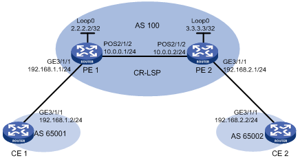
Configuration procedure
1. Configure OSPF, ensuring that PE 1 and PE 2 can learn routes from each other.
# Configure PE 1.
<PE1> system-view
[PE1] interface loopback 0
[PE1-LoopBack0] ip address 2.2.2.2 255.255.255.255
[PE1-LoopBack0] quit
[PE1] interface pos 2/1/2
[PE1-POS2/1/2] clock master
[PE1-POS2/1/2] ip address 10.0.0.1 255.255.255.0
[PE1-POS2/1/2] quit
[PE1] ospf
[PE1-ospf-1] area 0
[PE1-ospf-1-area-0.0.0.0] network 10.0.0.0 0.0.0.255
[PE1-ospf-1-area-0.0.0.0] network 2.2.2.2 0.0.0.0
[PE1-ospf-1-area-0.0.0.0] quit
[PE1-ospf-1] quit
# Configure PE 2.
<PE2> system-view
[PE2] interface loopback 0
[PE2-LoopBack0] ip address 3.3.3.3 255.255.255.255
[PE2-LoopBack0] quit
[PE2] interface pos 2/1/2
[PE2-POS2/1/2] ip address 10.0.0.2 255.255.255.0
[PE2-POS2/1/2] quit
[PE2] ospf
[PE2-ospf-1] area 0
[PE2-ospf-1-area-0.0.0.0] network 10.0.0.0 0.0.0.255
[PE2-ospf-1-area-0.0.0.0] network 3.3.3.3 0.0.0.0
[PE2-ospf-1-area-0.0.0.0] quit
[PE2-ospf-1] quit
After you complete the configuration, the PEs should be able to establish the OSPF neighborship. Perform the display ospf peer command; you should see that the neighborship state is FULL. Perform the display ip routing-table command; you should see that the PEs learnt the routes to the loopback interfaces of each other. Take PE 1 for example:
[PE1] display ospf peer
OSPF Process 1 with Router ID 2.2.2.2
Neighbors
Area 0.0.0.0 interface 10.0.0.1(POS2/1/2)'s neighbors
Router ID: 3.3.3.3 Address: 10.0.0.2 GR State: Normal
State: Full Mode:Nbr is Master Priority: 1
DR: None BDR: None
Dead timer due in 30 sec
Neighbor is up for 00:01:00
Authentication Sequence: [ 0 ]
[PE1] display ip routing-table
Routing Tables: Public
Destinations : 7 Routes : 7
Destination/Mask Proto Pre Cost NextHop Interface
2.2.2.2/32 Direct 0 0 127.0.0.1 InLoop0
3.3.3.3/32 OSPF 10 1563 10.0.0.2 POS2/1/2
10.0.0.0/24 Direct 0 0 10.0.0.1 POS2/1/2
10.0.0.1/32 Direct 0 0 127.0.0.1 InLoop0
10.0.0.2/32 Direct 0 0 10.0.0.2 POS2/1/2
127.0.0.0/8 Direct 0 0 127.0.0.1 InLoop0
127.0.0.1/32 Direct 0 0 127.0.0.1 InLoop0
2. Configure MPLS basic capabilities and LDP.
# Configure PE 1.
[PE1] mpls lsr-id 2.2.2.2
[PE1] mpls
[PE1-mpls] lsp-trigger all
[PE1-mpls] quit
[PE1] mpls ldp
[PE1-mpls-ldp] quit
[PE1] interface pos 2/1/2
[PE1-POS2/1/2] mpls
[PE1-POS2/1/2] mpls ldp
[PE1-POS2/1/2] quit
# Configure PE 2.
[PE2] mpls lsr-id 3.3.3.3
[PE2] mpls
[PE2-mpls] lsp-trigger all
[PE2-mpls] quit
[PE2] mpls ldp
[PE2-mpls-ldp] quit
[PE2] interface pos 2/1/2
[PE2-POS2/1/2] mpls
[PE2-POS2/1/2] mpls ldp
[PE2-POS2/1/2] quit
After you complete the configuration, PEs should be able to set up LDP sessions. Perform the display mpls ldp session command; you should be able to see that the session state is operational. Take PE 1 for example:
[PE1] display mpls ldp session
LDP Session(s) in Public Network
------------------------------------------------------------------
Peer-ID Status LAM SsnRole FT MD5 KA-Sent/Rcv
------------------------------------------------------------------
3.3.3.3:0 Operational DU Passive Off Off 2/2
------------------------------------------------------------------
LAM : Label Advertisement Mode FT : Fault Tolerance
3. Enable MPLS TE, CSPF and OSPF TE
# Configure PE 1.
[PE1] mpls
[PE1-mpls] mpls te
[PE1-mpls] mpls te cspf
[PE1-mpls] quit
[PE1] interface pos 2/1/2
[PE1-POS2/1/2] mpls te
[PE1-POS2/1/2] quit
[PE1] ospf
[PE1-ospf-1] opaque-capability enable
[PE1-ospf-1] area 0
[PE1-ospf-1-area-0.0.0.0] mpls-te enable
[PE1-ospf-1-area-0.0.0.0] quit
[PE1-ospf-1] quit
# Configure PE 2.
[PE2] mpls
[PE2-mpls] mpls te
[PE2-mpls] mpls te cspf
[PE2-mpls] quit
[PE2] interface pos 2/1/2
[PE2-POS2/1/2] mpls te
[PE2-POS2/1/2] quit
[PE2] ospf
[PE2-ospf-1] opaque-capability enable
[PE2-ospf-1] area 0
[PE2-ospf-1-area-0.0.0.0] mpls-te enable
[PE2-ospf-1-area-0.0.0.0] quit
[PE2-ospf-1] quit
4. Configure an MPLS TE tunnel
# Create a TE tunnel with PE 1 as the headend and PE 2 as the tail. The signaling protocol is CR-LDP.
[PE1] interface tunnel 4
[PE1-Tunnel4] ip address 12.1.1.1 255.255.255.0
[PE1-Tunnel4] tunnel-protocol mpls te
[PE1-Tunnel4] destination 3.3.3.3
[PE1-Tunnel4] mpls te tunnel-id 10
[PE1-Tunnel4] mpls te signal-protocol crldp
[PE1-Tunnel4] mpls te commit
[PE1-Tunnel4] quit
# Perform the display interface tunnel command on PE 1. You can see that the tunnel interface is up.
5. Configure the VPN instance on each PE, and bind it to the interface connected to the CE
# Configure on CE 1.
<CE1> system-view
[CE1] interface GigabitEthernet 3/1/1
[CE1-GigabitEthernet3/1/1] ip address 192.168.1.2 255.255.255.0
[CE1-GigabitEthernet3/1/1] quit
# Configure the VPN instance on PE 1, and use CR-LSP for VPN setup. Bind the VPN instance with the interface connected to CE 1.
[PE1] ip vpn-instance vpn1
[PE1-vpn-instance-vpn1] route-distinguisher 100:1
[PE1-vpn-instance-vpn1] vpn-target 100:1 both
[PE1-vpn-instance-vpn1] tnl-policy policy1
[PE1-vpn-instance-vpn1] quit
[PE1] tunnel-policy policy1
[PE1-tunnel-policy-policy1] tunnel select-seq cr-lsp load-balance-number 1
[PE1-tunnel-policy-policy1] quit
[PE1] interface GigabitEthernet 3/1/1
[PE1-GigabitEthernet3/1/1] ip binding vpn-instance vpn1
[PE1-GigabitEthernet3/1/1] ip address 192.168.1.1 255.255.255.0
[PE1-GigabitEthernet3/1/1] quit
# Configure on CE 2.
<CE2> system-view
[CE2] interface GigabitEthernet 3/1/1
[CE2-GigabitEthernet3/1/1] ip address 192.168.2.2 255.255.255.0
[CE2-GigabitEthernet3/1/1] quit
# Configure the VPN instance on PE 2, and bind it with the interface connected to CE 2.
[PE2] ip vpn-instance vpn1
[PE2-vpn-instance-vpn1] route-distinguisher 100:2
[PE2-vpn-instance-vpn1] vpn-target 100:1 both
[PE2-vpn-instance-vpn1] quit
[PE2] interface GigabitEthernet 3/1/1
[PE2-GigabitEthernet3/1/1] ip binding vpn-instance vpn1
[PE2-GigabitEthernet3/1/1] ip address 192.168.2.1 255.255.255.0
[PE2-GigabitEthernet3/1/1] quit
# Perform the display ip vpn-instance command on the PEs to verify the configuration of the VPN instance. Take PE 1 for example:
[PE1] display ip vpn-instance instance-name vpn1
VPN-Instance Name and ID : vpn1, 1
Create time : 2006/09/27 15:10:29
Up time : 0 days, 00 hours, 03 minutes and 09 seconds
Route Distinguisher : 100:1
Export VPN Targets : 100:1
Import VPN Targets : 100:1
Tunnel Policy : policy1
Interfaces : GigabitEthernet3/1/1
# Ping connected CEs on PEs to test connectivity. For example, ping CE 1 on PE 1:
[PE1] ping -vpn-instance vpn1 192.168.1.2
PING 192.168.1.2: 56 data bytes, press CTRL_C to break
Reply from 192.168.1.2: bytes=56 Sequence=1 ttl=255 time=47 ms
Reply from 192.168.1.2: bytes=56 Sequence=2 ttl=255 time=26 ms
Reply from 192.168.1.2: bytes=56 Sequence=3 ttl=255 time=26 ms
Reply from 192.168.1.2: bytes=56 Sequence=4 ttl=255 time=26 ms
Reply from 192.168.1.2: bytes=56 Sequence=5 ttl=255 time=26 ms
--- 192.168.1.2 ping statistics ---
5 packet(s) transmitted
5 packet(s) received
0.00% packet loss
round-trip min/avg/max = 26/30/47 ms
The output shows that PE 1 can reach CE 1.
6. Configure BGP
# Configure CE 1.
[CE1] bgp 65001
[CE1-bgp] peer 192.168.1.1 as-number 100
[CE1-bgp] quit
# Configure PE 1 to establish the EBGP peer relationship with CE 1, and the IBGP peer relationship with PE 2.
[PE1] bgp 100
[PE1-bgp] ipv4-family vpn-instance vpn1
[PE1-bgp-vpn1] peer 192.168.1.2 as-number 65001
[PE1-bgp-vpn1] import-route direct
[PE1-bgp-vpn1] quit
[PE1-bgp] peer 3.3.3.3 as-number 100
[PE1-bgp] peer 3.3.3.3 connect-interface loopback 0
[PE1-bgp] ipv4-family vpnv4
[PE1-bgp-af-vpnv4] peer 3.3.3.3 enable
[PE1-bgp-af-vpnv4] quit
[PE1-bgp] quit
# Configure CE 2.
[CE2] bgp 65002
[CE2-bgp] peer 192.168.2.1 as-number 100
[CE2-bgp] quit
# Configure PE 2 to establish the EBGP peer relationship with CE 2 and the IBGP relationship with PE 1.
[PE2] bgp 100
[PE2-bgp] ipv4-family vpn-instance vpn1
[PE2-bgp-vpn1] peer 192.168.2.2 as-number 65002
[PE2-bgp-vpn1] import-route direct
[PE2-bgp-vpn1] quit
[PE2-bgp] peer 2.2.2.2 as-number 100
[PE2-bgp] peer 2.2.2.2 connect-interface loopback 0
[PE2-bgp] ipv4-family vpnv4
[PE2-bgp-af-vpnv4] peer 2.2.2.2 enable
[PE2-bgp-af-vpnv4] quit
[PE2-bgp] quit
# Perform the display bgp peer command and the display bgp vpn-instance peer command on PEs. You can see that the BGP peer relationships have been formed between PEs and between PEs and CEs and have reached the established state. Take PE 1 for example:
[PE1-bgp] display bgp peer
BGP local router ID : 2.2.2.2
Local AS number : 100
Total number of peers : 1 Peers in established state : 1
Peer V AS MsgRcvd MsgSent OutQ Up/Down State PrefRcv
3.3.3.3 4 100 3 3 0 00:00:11 Established 0
[PE1-bgp] display bgp vpn-instance vpn1 peer
BGP local router ID : 2.2.2.2
Local AS number : 100
Total number of peers : 1 Peers in established state : 1
Peer V AS MsgRcvd MsgSent OutQ Up/Down State PrefRcv
192.168.1.2 4 65001 4 5 0 00:02:13 Established 0
# Ping CE 2 on CE 1 and vice versa to test connectivity.
[CE1] ping 192.168.2.2
PING 192.168.2.2: 56 data bytes, press CTRL_C to break
Reply from 192.168.2.2: bytes=56 Sequence=1 ttl=253 time=61 ms
Reply from 192.168.2.2: bytes=56 Sequence=2 ttl=253 time=54 ms
Reply from 192.168.2.2: bytes=56 Sequence=3 ttl=253 time=53 ms
Reply from 192.168.2.2: bytes=56 Sequence=4 ttl=253 time=57 ms
Reply from 192.168.2.2: bytes=56 Sequence=5 ttl=253 time=36 ms
--- 192.168.2.2 ping statistics ---
5 packet(s) transmitted
5 packet(s) received
0.00% packet loss
round-trip min/avg/max = 36/52/61 ms
[CE2] ping 192.168.1.2
PING 192.168.1.2: 56 data bytes, press CTRL_C to break
Reply from 192.168.1.2: bytes=56 Sequence=1 ttl=253 time=38 ms
Reply from 192.168.1.2: bytes=56 Sequence=2 ttl=253 time=61 ms
Reply from 192.168.1.2: bytes=56 Sequence=3 ttl=253 time=74 ms
Reply from 192.168.1.2: bytes=56 Sequence=4 ttl=253 time=36 ms
Reply from 192.168.1.2: bytes=56 Sequence=5 ttl=253 time=35 ms
--- 192.168.1.2 ping statistics ---
5 packet(s) transmitted
5 packet(s) received
0.00% packet loss
round-trip min/avg/max = 35/48/74 ms
The output shows that CE 1 and CE 2 can reach each other.
7. Verify the configuration
# Perform the display mpls lsp verbose command on PE 1. You can find an LSP with LspIndex 2050. This is the LSP, that is, the MPLS TE tunnel, established using CR-LDP.
[PE1] display mpls lsp verbose
------------------------------------------------------------------
LSP Information: CRLDP LSP
------------------------------------------------------------------
No : 1
IngressLsrID : 2.2.2.2
LocalLspID : 1
Tunnel-Interface : Tunnel4
Fec : 3.3.3.3/32
Nexthop : 10.0.0.2
In-Label : NULL
Out-Label : 1024
In-Interface : ----------
Out-Interface : POS2/1/2
LspIndex : 2050
Tunnel ID : 0x22004
LsrType : Ingress
Bypass In Use : Not Exists
BypassTunnel : Tunnel Index[---]
Mpls-Mtu : 1500
------------------------------------------------------------------
LSP Information: BGP LSP
------------------------------------------------------------------
No : 2
VrfIndex : vpn1
Fec : 192.168.1.0/24
Nexthop : 192.168.1.1
In-Label : 1024
Out-Label : NULL
In-Interface : ----------
Out-Interface : ----------
LspIndex : 8193
Tunnel ID : 0x0
LsrType : Egress
Outgoing Tunnel ID : 0x0
Label Operation : POP
------------------------------------------------------------------
LSP Information: LDP LSP
------------------------------------------------------------------
No : 3
VrfIndex :
Fec : 2.2.2.2/32
Nexthop : 127.0.0.1
In-Label : 3
Out-Label : NULL
In-Interface : POS2/1/2
Out-Interface : ----------
LspIndex : 10241
Tunnel ID : 0x0
LsrType : Egress
Outgoing Tunnel ID : 0x0
Label Operation : POP
No : 4
VrfIndex :
Fec : 3.3.3.3/32
Nexthop : 10.0.0.2
In-Label : NULL
Out-Label : 3
In-Interface : ----------
Out-Interface : POS2/1/2
LspIndex : 10242
Tunnel ID : 0x22000
LsrType : Ingress
Outgoing Tunnel ID : 0x0
Label Operation : PUSH
# Perform the display interface tunnel command on PE 1. The output shows that traffic is being forwarded along the CR-LSP of the TE tunnel.
[PE1] display interface tunnel 4
Tunnel1 current state: UP
Line protocol current state: UP
Description: Tunnel1 Interface
The Maximum Transmit Unit is 1500
Internet Address is 12.1.1.1/24 Primary
Encapsulation is TUNNEL, service-loopback-group ID not set
Tunnel source unknown, destination 3.3.3.3
Tunnel protocol/transport CR_LSP
Output queue : (Urgent queuing : Size/Length/Discards) 0/100/0
Output queue : (Protocol queuing : Size/Length/Discards) 0/500/0
Output queue : (FIFO queuing : Size/Length/Discards) 0/75/0
Last 300 seconds input: 5 bytes/sec, 0 packets/sec
Last 300 seconds output: 5 bytes/sec, 0 packets/sec
34 packets input, 2856 bytes
0 input error
34 packets output, 2856 bytes
0 output error
Troubleshooting MPLS TE
No TE LSA generated
Symptom
OSPF TE is configured but no TE LSAs can be generated to describe MPLS TE attributes.
Analysis
For TE LSAs to be generated, at least one OSPF neighbor must reach the FULL state.
Solution
1. Perform the display current-configuration command to check that MPLS TE is configured on involved interfaces.
2. Perform the debugging ospf mpls-te command to observe whether OSPF can receive the TE LINK establishment message.
3. Perform the display ospf peer command to check that OSPF neighbors are established correctly.
Swicthback fails to occur when the main tunnel resumes
Symptom
When data is transmitted along the protection tunnel, the main tunnel becomes normal but data still travels along the protection tunnel. In the output of the display mpls te protection tunnel command, the Switch Result field has a value of Protect-tunnel and the Work-tunnel defect state field has a value of No-defect.
Analysis
Possible reasons include:
· The reverting mode is non-revertive.
· The reverting delay period is relatively long.
· A switching command with higher priority forces data to travel along the protection tunnel.
Solution
1. Execute the display mpls te protection tunnel command. If the Mode field in the output is Non-revertive, the configuration defines that reverting should not occur. If you expect that protection switching will be triggered when the main tunnel recovers, you can configure the mpls te protection tunnel command in the main tunnel interface view to set the reverting mode as revertive.
2. If the Mode field is revertive and the WTR field is a non-zero value, the reverting delay timer has expired. When the timer expires, if the main tunnel still has no defect, data will be switched back to the main tunnel. If you hope the switchover occurs immediately when the main tunnel recovers, you can use the mpls te protection tunnel command to change the reverting delay time to 0.
3. If your case is neither 1) nor 2), check the The current switch command field in the output of the display mpls te protection tunnel command. If its value is Force, a switching action with a higher priority than the signal switching is configured. If you expect that signaling can trigger switchover when the main tunnel recovers, you can use the mpls te protect-switch clear command to clear all configured switching actions.