- Table of Contents
- Related Documents
-
| Title | Size | Download |
|---|---|---|
| 04-MPLS L2VPN Configuration | 391.57 KB |
Contents
MPLS L2VPN configuration task list
Configuring Martini MPLS L2VPN
Creating a Martini MPLS L2VPN connection on a Layer 3 Ethernet interface/sub-interface
Creating a Martini MPLS L2VPN for a service instance
Configuring Kompella MPLS L2VPN
Enabling the MPLS L2VPN mix function
Displaying and maintaining MPLS L2VPN
Displaying the operation of MPLS L2VPN
Resetting BGP L2VPN connections
MPLS L2VPN configuration examples
Example for configuring a local CCC connection
Example for configuring a remote CCC connection
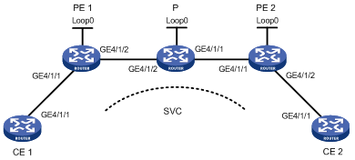
Example for configuring SVC MPLS L2VPN
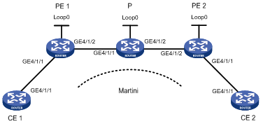
Example for configuring Martini MPLS L2VPN
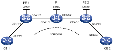
Example for configuring Kompella MPLS L2VPN
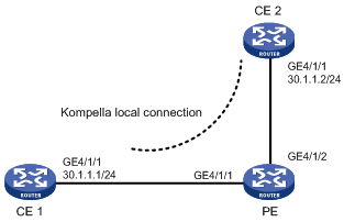
Example for configuring a Kompella local connection
|
|
NOTE: · In this documentation, SPC cards refer to the cards prefixed with SPC, for example, SPC-GT48L, and SPE cards refer to the cards prefixed with SPE, for example, SPE-1020-E-II. · SPC cards do not support CCC, SVC, or Kompella MPLS L2VPNs. · SPC cards only support binding a Layer 2 Ethernet port with an L2VPN. They do not support binding a Layer 3 Ethernet interface with an L2VPN. |
MPLS L2VPN overview
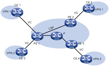
MPLS L2VPN provides Layer 2 VPN services on the MPLS network. It allows carriers to establish L2VPNs on different data link layer protocols, including ATM, VLAN, Ethernet and PPP.
MPLS L2VPN transfers Layer 2 user data transparently on the MPLS network. For users, the MPLS network is a Layer 2 switched network and they can establish Layer 2 connections over the network.
Consider ATM as an example. Each customer edge (CE) device can connect to the MPLS network through an ATM virtual circuit (VC) to communicate with another CE. This is similar to that of an ATM network.
Figure 1 Network diagram for MPLS L2VPN
Comparison with MPLS L3VPN
Compared with MPLS L3VPN, MPLS L2VPN has the following advantages:
· High scalability. MPLS L2VPN establishes only Layer 2 connections. It does not involve the routing information of users. This greatly reduces the load of the PEs and even the load of the whole service provider network, enabling carriers to support more VPNs and to service more users.
· Guaranteed reliability and private routing information security. As no routing information of users is involved, MPLS L2VPN neither tries to obtain nor processes the routing information of users, guaranteeing the security of the user VPN routing information.
· Support for multiple network layer protocols, such as IP, IPX, and SNA.
Basic concepts of MPLS L2VPN
In MPLS L2VPN, the concepts and principles of CE, PE and P are the same as those in MPLS L3VPN:
· Customer edge (CE) device—A CE resides on a customer network and has one or more interfaces directly connected to service provider networks. It can be a router, a switch, or a host. It can neither “sense” the presence of any VPN nor does it need to support MPLS.
· Provider edge (PE) device—A PE resides at the edge of a service provider network and connects one or more CEs. On an MPLS network, all VPN services are processed on the PEs.
· Provider (P) device—A P device is a core device on a service provider network. It is not directly connected to any CE. It has only basic MPLS forwarding capability.
MPLS L2VPN uses label stacks to implement the transparent transmission of user packets in the MPLS network.
· Outer label, also called tunnel label, is used to transfer packets from one PE to another.
· Inner label, also called VC label, is used to identify different connections between VPNs.
· Upon receiving packets, a PE determines to which CE the packets are to be forwarded according to the VC labels.
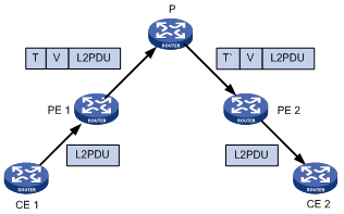
Figure 2 illustrates how the label stack changes in the MPLS L2VPN forwarding process.
Figure 2 MPLS L2VPN label stack processing
|
1) L2 PDU: Layer 2 protocol data unit |
|
2) T represents tunnel label. V represents VC label. T’ represents swapped tunnel label. |
Implementation of MPLS L2VPN
MPLS L2VPN can be implemented in one of the following methods:
· Circuit Cross Connect (CCC) and Static Virtual Circuit (SVC)—Two methods of implementing MPLS L2VPN by configuring VC labels statically.
· Martini—A method for establishing PPP links to implement MPLS L2VPN. It uses Label Distribution Protocol (LDP) as a signaling protocol to transfer VC labels.
· Kompella—A CE-to-CE mode for implementing MPLS L2VPN on the MPLS network. It uses extended BGP as the signaling protocol to advertise Layer 2 reachability information and VC labels.
The following sections describe these implementation methods for MPLS L2VPN in detail.
CCC MPLS L2VPN
Unlike common MPLS L2VPN, CCC employs just one level of label to transfer user data. Therefore, it uses label switched paths (LSPs) exclusively. A CCC LSP can transfer only the data of the CCC connection; it can neither be used for other MPLS L2VPN connections, nor for MPLS L3VPN or common IP packets.
The most significant advantage of this method is that no label signaling is required for transferring Layer 2 VPN information. As long as MPLS forwarding is supported and service provider networks are interconnected, this method works perfectly. In addition, since LSPs are dedicated, this method supports QoS services.
There are two types of CCC connections:
· Local connection—A local connection is established between two local CEs that are connected to the same PE. The PE functions like a Layer 2 switch and can directly switch packets between the CEs without any static LSP.
· Remote connection—A remote connection is established between a local CE and a remote CE, which are connected to different PEs.
|
|
NOTE: You must configure for each remote CCC connection two LSPs, one for inbound and the other for outbound, on the P router along the remote connection. |
SVC MPLS L2VPN
SVC also implements MPLS L2VPN by static configuration. It transfers L2VPN information without using any signaling protocol.
The SVC method resembles the Martini method closely and is in fact a static implementation of the Martini method. The difference is that it does not use LDP to transfer Layer 2 VC and link information. You only need to configure VC label information.
|
|
NOTE: The labels for CCC and SVC range from 16 to 1023, which are reserved for static LSPs. |
Martini MPLS L2VPN
The key of the Martini method is to set up VCs between CEs.
Martini MPLS L2VPN employs VC type and VC ID to identify a VC. The VC type indicates the encapsulation type of the VC, which can be ATM, VLAN, or PPP. The VC ID uniquely identifies the VC among the VCs of the same type on a PE.
The PEs connecting the two CEs of a VC exchange VC labels through LDP, and bind their respective CE by the VC ID.
Once LDP establishes an LSP between the two PEs and the label exchange and the binding to CE are finished, a VC is set up and ready to transfer Layer 2 data.
To allow the exchange of VC labels between PEs, the Martini method extended LDP by adding the forwarding equivalence class (FEC) type of VC FEC. Moreover, as the two PEs exchanging VC labels may not be connected directly, a remote LDP session must be set up to transfer the VC FEC and VC labels.
With Martini MPLS L2VPN, only PEs need to maintain a small amount of VC labels and LSP mappings and no P router contains Layer 2 VPN information. Therefore, it has high scalability. In addition, to add a new VC, you only need to configure a one-way VC for each of the PEs. Your configuration will not affect the operation of the network.
The Martini method applies to scenarios with sparse Layer 2 connections, such as a scenario with a star topology.
Kompella MPLS L2VPN
Kompella MPLS L2VPN is different from Martini MPLS L2VPN in that it does not operate on the connections between CEs directly. It organizes different VPNs in the whole service provider network and encodes each CE in a VPN. For a connection to be established between two CEs, you only need to perform these tasks on the PEs:
· Configuring CE IDs of the local and remote CEs respectively
· Specifying the circuit ID that the local CE assigns to the connection, such as the VPI/VCI with ATM.
Kompella MPLS L2VPN uses extended BGP as the signaling protocol to distribute VC labels. Its label block mode allows it to assign labels to multiple connections at a time.
With Kompella MPLS L2VPN, you can specify the CE range of a VPN to indicate how many CEs can be connected to the VPN. Then, the system assigns a label block of a size equal to the CE range for the CE. In this way, you can reserve some labels for the VPN for future use. This wastes some label resources in a short term, but can reduce the VPN deployment and configuration workload in the case of expansion.
Imagine that an enterprise VPN contains 10 CEs and the number may increase to 20 in future service expansion. In this case, you can set the CE range of each CE to 20. Thus, when you need to add a CE to the VPN later, you only need to modify the configurations of the PE to which the new CE is connected. No change is required for the other PEs. This makes VPN expansion extremely simple.
Similar to MPLS L3VPN, Kompella MPLS L2VPN also uses VPN targets to identify VPNs. This brings excellent VPN networking flexibility.
In addition, Kompella supports local connections.
MPLS L2VPN configuration task list
Complete the following tasks to configure MPLS L2VPN:
|
Task |
Remarks |
|
Required |
|
|
Use one of the approaches according to the MPLS L2VPN implementation method |
|
|
Optional |
|
|
NOTE: After you create an MPLS L2VPN connection on a Layer 3 interface, IP related functions on the sub-interfaces of the Layer 3 interface will fail. For example, the sub-interfaces cannot receive ARP or IGMP packets; they cannot forward unicast or multicast packets. After you remove the MPLS L2VPN connection, the IP related functions on the sub-interfaces recover. |
Configuring MPLS L2VPN
You can select any of the implementation methods for MPLS L2VPN as needed. However, no matter what method you select, you must complete the following tasks:
· Configure basic MPLS
· Enable L2VPN
· Enable MPLS L2VPN
To perform basic MPLS L2VPN configurations:
|
Step |
Command |
Remarks |
|
1. Enter system view. |
system-view |
N/A |
|
2. Configure the LSR ID. |
mpls lsr-id lsr-id |
N/A |
|
3. Configure basic MPLS and enter MPLS view. |
mpls |
N/A |
|
4. Return to system view. |
quit |
N/A |
|
5. Enable L2VPN and enter L2VPN view. |
l2vpn |
Disabled by default |
|
6. Specify the reserved VLAN for MPLS L2VPN. |
mpls l2vpn reserve vlan vlan-id |
Optional |
|
7. Enable MPLS L2VPN. |
mpls l2vpn |
Disabled by default |
Configuring CCC MPLS L2VPN
Configuration prerequisites
Before configuring CCC L2VPN, complete the following tasks:
· Configure basic MPLS on the PEs and P routers.
· Enable MPLS L2VPN on the PEs of the MPLS backbone. You do not need to enable MPLS L2VPN on the P routers.
To configure CCC MPLS L2VPN, you need the following data:
· Name for the CCC connection
· Connection type: local or remote
· For a local CCC connection: the types and numbers of the incoming and outgoing interfaces
· For a remote CCC connection: the type and number of the incoming interface, the address of the next hop or the type and number of the outgoing interface, and the incoming and outgoing labels of the LSRs along the CCC connection
Configuration procedure
Configuring the local CCC connection
To create a local CCC connection on a PE:
|
Command |
|
|
1. Enter system view. |
system-view |
|
2. Create a local CCC connection between two CEs connected to the same PE. |
ccc ccc-connection-name interface interface-type interface-number out-interface interface-type interface-number |
Configuring the remote CCC connection
1. Configure the PEs
To configure a PE:
|
Step |
Command |
|
1. Enter system view. |
system-view |
|
2. Create a remote CCC connection between CEs connected to different PEs. |
ccc ccc-connection-name interface interface-type interface-number in-label in-label-value out-label out-label-value { nexthop ip-address | out-interface interface-type interface-number } [ control-word | no-control-word ] |
|
|
CAUTION: · You do not need to configure two static LSPs for each remote CCC connection. Instead, you only need to configure the incoming and outgoing labels, where the incoming label must be exclusively for the CCC connection. The labels function as static LSPs. · Only when the link that the outgoing interface connects is a point-to-point link, can you use the out-interface keyword to specify the outgoing interface. If the link is not a point-to-point link but, for example, a link connecting to Layer 3 Ethernet interface, VLAN interface, or Layer 3 aggregate interface, you must use the nexthop keyword to specify the IP address of the next hop. |
To configure a P router:
|
Step |
Command |
|
1. Enter system view. |
system-view |
|
2. Configure a transit static LSP. |
static-lsp transit lsp-name incoming-interface interface-type interface-number in-label in-label { nexthop next-hop-addr | outgoing-interface interface-type interface-number } out-label out-label |
|
|
CAUTION: · With CCC, no static LSPs are required on the PEs but dedicated bidirectional static LSPs are required on all the P routers between the PEs for transmitting the data of the CCC connection. · For static LSP configuration commands, see MPLS Command Reference. · You cannot enable both VLL and MPLS on an interface of the router, for example, a routing interface or routing sub-interface. Otherwise, neither the MPLS service nor the MPLS L2VPN service can work normally and you must remove both of the two services first for further service configuration. · If a Layer 3 Ethernet interface is bound with an L2VPN, the Layer 3 Ethernet sub-interfaces of the Layer 3 Ethernet interface cannot be bound with any L2VPN or VPLS instance. If a Layer 3 Ethernet sub-interface is bound with an L2VPN, the Layer 3 Ethernet interface of the sub-interface cannot be bound with any L2VPN or VPLS instance. |
Configuring SVC MPLS L2VPN
SVC MPLS L2VPN does not use any signaling protocol to transfer L2VPN information. Instead, it uses tunnels to transport data between PEs.
SVC supports these tunnel types: LDP LSP, and CR-LSP. By default, LDP LSP tunnels are used.
Configuration prerequisites
Before configuring SVC MPLS L2VPN, complete these tasks:
· Configuring IGP on the PEs and P routers to guarantee the IP connectivity of the MPLS backbone
· Configuring basic MPLS and MPLS LDP for the MPLS backbone on the PEs and P routers to establish LDP LSPs
· Enabling MPLS L2VPN on the PEs
· Establishing the tunnels between PEs according to the tunneling policy.
To configure SVC MPLS L2VPN, you need the following data:
· Types and numbers of the interfaces connecting the CEs
· Destination LSR ID of SVC
· Incoming and outgoing labels of the L2VPN connection
· SVC tunneling policy
Configuration procedure
To configure SVC MPLS L2VPN on the PE:
|
Step |
Command |
|
1. Enter system view. |
system-view |
|
2. Enter interface view for the interface connecting the CE. |
interface interface-type interface-number |
|
3. Create an SVC MPLS L2VPN connection. |
mpls static-l2vc destination destination-router-id transmit-vpn-label transmit-label-value receive-vpn-label receive-label-value [ { control-word | ethernet | no-control-word | vlan } | tunnel-policy tunnel-policy-name ] * |
|
|
CAUTION: · You need to ensure the validity of incoming labels and outgoing labels in an SVC L2VPN. · You cannot enable both VLL and MPLS on an interface of the router, for example, a routing interface or routing sub-interface. Otherwise, neither the MPLS service nor the MPLS L2VPN service can work normally and you must remove both of the two services first for further service configuration. · If a Layer 3 Ethernet interface is bound with an L2VPN, the Layer 3 Ethernet sub-interfaces of the Layer 3 Ethernet interface cannot be bound with any L2VPN or VPLS instance. If a Layer 3 Ethernet sub-interface is bound with an L2VPN, the Layer 3 Ethernet interface of the sub-interface cannot be bound with any L2VPN or VPLS instance. |
Configuring Martini MPLS L2VPN
You can create a Martini MPLS L2VPN connection in either of the following ways:
· Configuring it on a Layer 3 interface that is not a VLAN interface (see “Creating a Martini MPLS L2VPN connection on a Layer 3 Ethernet interface/sub-interface”).
· Configuring it in a service instance (see “Creating a Martini MPLS L2VPN for a service instance”).
Creating a Martini MPLS L2VPN connection on a Layer 3 Ethernet interface/sub-interface
Martini MPLS L2VPN uses extended LDP to transfer Layer 2 information and VC labels. To configure Martini MPLS L2VPN, you need to:
· Create a Martini MPLS L2VPN connection
After a Martini MPLS L2VPN connection is created on a Layer 3 Ethernet interface/sub-interface, packets arriving at the interface are forwarded through the MPLS L2VPN connection.
· Configure the remote peer
In Martini MPLS L2VPN implementation, VC labels need to be exchanged between PEs. Because two PEs may not be connected to each other directly, you need to establish a remote LDP session between the two PEs, so that VC FECs and VC labels can be transferred through the session.
Configuration prerequisites
Before you configure Martini MPLS L2VPN, complete the following tasks:
· Configure an IGP on the PEs and P routers to ensure IP connectivity within the MPLS backbone
· Configure basic MPLS and MPLS LDP on the PEs and P routers to establish LDP LSPs
· Enable MPLS L2VPN on the PEs
· Establish remote LDP sessions between PEs
To configure Martini MPLS L2VPN, prepare the following data:
· Types and numbers of the interfaces connecting the CEs
· Destination address of the L2VPN connection and the PW ID (VC ID)
· PW class template
Configuration procedure
To configure a Martini MPLS L2VPN connection on a Layer 3 Ethernet interface/sub-interface of the PE:
|
Step |
Command |
Remarks |
|
1. Enter system view. |
system-view |
N/A |
|
2. Enter interface view for the interface connecting the CE. |
interface interface-type interface-number |
The interface must be a Layer 3 Ethernet interface/sub-interface. |
|
3. Create a Martini MPLS L2VPN connection. |
mpls l2vc destination vcid [ { control-word | ethernet | no-control-word | vlan } | tunnel-policy tunnel-policy-name ] * |
N/A |
|
4. Return to system view. |
quit |
N/A |
|
5. Configure an MPLS LDP remote peer entity and enter its view. |
mpls ldp remote-peer remote-peer-name |
N/A |
|
6. Specify an IP address for the remote peer. |
remote-ip ip-address |
N/A |
|
|
NOTE: For remote peer configuration information, see the chapter “Configuring basic MPLS configuration.” |
|
|
CAUTION: · A Martini connection has two main parameters: IP address of the peer PE, and VC ID. · Do not configure both MPLS and Martini MPLS L2VPN on a Layer 3 Ethernet interface/sub-interface. Otherwise, neither MPLS nor MPLS L2VPN service can work normally, and you must remove both services first for further service configuration. · If a Layer 3 Ethernet interface is bound with an L2VPN, the Layer 3 Ethernet sub-interfaces of the Layer 3 Ethernet interface cannot be bound with any L2VPN or VPLS instance. If a Layer 3 Ethernet sub-interface is bound with an L2VPN, the Layer 3 Ethernet interface of the sub-interface cannot be bound with any L2VPN or VPLS instance. · You must configure the PVC and MAP for an ATM interface before using the mpls l2vc destination vcid [ tunnel-policy tunnel-policy-name ] [ control-word | no-control-word ] [ ethernet | vlan ] command on the ATM interface. For more information about PVC and MAP configuration, see Layer 2—WAN Configuration Guide. · When configuring a Martini MPLS L2VPN connection on a Layer 3 Ethernet sub-interface on an SPC card, you must configure the PW encapsulation mode as VLAN. Otherwise, packets may not be forwarded correctly. |
Creating a Martini MPLS L2VPN for a service instance
|
|
NOTE: · Do not configure services other than L2VPN for the VLAN that is bound to the private network side of the MPLS L2VPN. · Do not enable port-based protocols such as STP, Ethernet OAM, 802.1X, GVRP, LLDP, DLDP, and LACP on a port enabled with MPLS L2VPN. · For an MPLS L2VPN connection created for a service instance, if the access mode of the service instance is Ethernet, do not use a trunk port to connect the private network side. You can add this port to the access VLAN as an access port, or configure the port as a hybrid port that permits packets from the access VLAN to pass with the VLAN tag stripped. |
If you create a Martini MPLS L2VPN connection on a VLAN interface, all packets carrying the tag of the VLAN will be forwarded through the MPLS L2VPN connection, no matter from which Layer 2 Ethernet ports the packets are received. That is, the router chooses an MPLS L2VPN connection for a received packet according to only the VLAN tag carried in the packet. This not only wastes the Layer 2 Ethernet port and VLAN resources but also mixes the users and services of different Layer 2 Ethernet ports.
To solve the problem, you can create a Martini MPLS L2VPN connection in a service instance. More specifically:
1. Create a service instance on a Layer 2 Ethernet port.
2. Specify a packet matching VLAN ID for the service instance.
3. Create a Martini MPLS L2VPN connection in the service instance view.
Then, packets arriving at the Layer 2 Ethernet port and carrying the specified VLAN ID will be forwarded by the MPLS L2VPN connection.
Configuration prerequisites
Before you configure Martini MPLS L2VPN, complete the following tasks:
· Configure an IGP on the PEs and P routers to ensure IP connectivity within the MPLS backbone
· Configure basic MPLS and MPLS LDP on the PEs and P routers to establish LDP LSPs
· Enable MPLS L2VPN on the PEs
To configure Martini MPLS L2VPN, prepare the following data:
· Types and numbers of the interfaces connecting the CEs
· Destination address of the L2VPN connection and the PW ID
· PW class template
Configuration procedure
To create a Martini MPLS L2VPN connection in a service instance:
|
Step |
Command |
Remarks |
|
1. Enter system view. |
system-view |
N/A |
|
2. Create a PW class template and enter PW class template view. |
pw-class pw-class-name |
Optional. By default, no PW class template is created. |
|
3. Specify the PW transport mode. |
trans-mode { ethernet | vlan } |
Optional. VLAN by default. |
|
4. Specify the tunneling policy. |
pw-tunnel-policy policy-name |
Optional. By default, the default tunneling policy is used. The default tunneling policy selects only one tunnel (no load balancing) in this order: LSP tunnel, CR-LSP tunnel. |
|
5. Return to system view. |
quit |
N/A |
|
6. Create the VLAN to be used by the service instance to match packets. |
vlan vlan-id |
N/A |
|
7. Add the Layer 2 port connecting the CE to the VLAN. |
port interface |
N/A |
|
8. Return to system view. |
quit |
N/A |
|
9. Configure an MPLS LDP remote peer entity and enter its view. |
mpls ldp remote-peer remote-peer-name |
N/A |
|
10. Specify an IP address for the remote peer. |
remote-ip ip-address |
N/A |
|
11. Enter the configuration view of the Layer 2 port that connects with the CE. |
interface interface-type interface-number |
N/A |
|
12. Create a service instance and enter service instance view. |
service-instance instance-id |
By default, no service instance is created. |
|
13. Specify a packet matching VLAN ID for the service instance. |
encapsulation s-vid vlan-id |
By default, no packet matching VLAN ID is specified for the service instance. |
|
14. Create a Martini MPLS L2VPN connection in the service instance. |
xconnect peer peer-ip-address pw-id pw-id [ access-mode { ethernet | vlan } | mtu mtu-value | [ pw-class class-name ] ] * |
After this command is executed, the VLAN ID, access mode, and MTU configured for the service instance cannot be changed. To modify these parameters, you must use the undo xconnect peer command to remove the L2VPN connection first. |
|
|
NOTE: · You can configure up to 4094 service instances on a Layer 2 Ethernet port. · The xconnect peer command is available for service instances with the ID in the range of 1 to 4094. |
Configuring Kompella MPLS L2VPN
Kompella MPLS L2VPN uses extended BGP as the signaling protocol to transfer L2VPN information between PEs.
To create a Kompella local connection, you only need to configure the VPN and CE connection on the PE. Neither IGP nor BGP L2VPN capability is required.
Configuration prerequisites
Before configuring Kompella MPLS L2VPN, complete the following tasks:
· Configure an IGP on the PEs and P routers to ensure IP connectivity within the MPLS backbone
· Configure basic MPLS and MPLS LDP on the PEs and P routers to establish LDP LSPs
· Enable MPLS L2VPN on the PEs
To configure Kompella MPLS L2VPN, prepare the following data:
· AS numbers of the local PE and the peer PE
· Name, RD, and VPN Target attributes of the L2VPN connection
· CE name, CE ID, and CE range
· CE offset
Configuration procedure
Configuring BGP L2VPN capability
To configure BGP L2VPN capability:
|
Step |
Command |
Remarks |
|
1. Enter system view. |
system-view |
N/A |
|
2. Enter BGP view. |
bgp as-number |
N/A |
|
3. Establish the peer relationship with the peer PE. |
peer { group-name | ip-address } as-number as-number |
N/A |
|
4. Specify the interface for the TCP connection. |
peer { group-name | ip-address } connect-interface interface-type interface-number |
N/A |
|
5. Enter BGP L2VPN address family view. |
l2vpn-family |
N/A |
|
6. Enable the filtering by the VPN target extended community attributes for the received routing information. |
policy vpn-target |
Optional Enabled by default |
|
7. Enable the specified peer or peers to exchange BGP routing information of the BGP-L2VPN address family. |
peer { group-name | ip-address } enable |
N/A |
|
|
NOTE: For information about the configuration of BGP-L2VPN address family, see the chapter “Configuring MPLS L3VPN.” |
Configuring VPN
To configure VPN:
|
Step |
Command |
Remarks |
|
1. Enter system view. |
system-view |
N/A |
|
2. Create a VPN and enter MPLS L2VPN view. |
mpls l2vpn vpn-name [ encapsulation { atm-aal5 | ethernet | fr | hdlc | ppp | vlan } [ control-word | no-control-word ] ] |
N/A |
|
3. Configure an RD for the L2VPN. |
route-distinguisher route-distinguisher |
N/A |
|
4. Associate a particular VPN with one or more VPN targets. |
vpn-target vpn-target&<1-16> [ both | export-extcommunity | import-extcommunity ] |
N/A |
|
5. Set the Layer 2 MTU for the VPN. |
mtu mtu |
Optional |
|
|
CAUTION: · H3C does not recommend configuring the mtu command. It affects only possible parameter negotiations. It does not affect data forwarding. · With Kompella MPLS L2VPN, you must create on the PE an L2VPN instance for each VPN where a directly connected CE resides. When creating an L2VPN, you must specify an encapsulation type matching that of the CE side interface. · The configuration of the VPN targets and RD are the same as that for MPLS L3VPN. For Kompella MPLS L2VPN, the RD is required. Once configured, an RD cannot be changed, unless you delete the L2VPN and then re-create it. · When configuring a Kompella MPLS L2VPN connection on a Layer 3 Ethernet sub-interface on an SPC card, you must configure the VPN encapsulation mode as VLAN. Otherwise, packets may not be forwarded correctly. |
Creating a CE Connection
CE ID is used for identifying a CE uniquely in a VPN. To facilitate the configuration, encode the CE IDs in continuous natural numbers starting from 1.
The CE range of a VPN indicates the maximum number of CEs that can be connected to the VPN. You can configure a CE range greater than what is required based on your estimate of the future VPN expansion if the label resources are abundant (they are usually abundant). This can reduce the configuration modification required when CEs are added in the VPN in future.
When creating a CE connection, if you do not specify the CE offset:
· For the first connection of the CE, the CE offset is the value specified by the default-offset parameter in the ce command.
· For any other connection of the CE, the CE offset is that of the former connection plus 1.
· When you plan a VPN, H3C recommends encoding CE IDs in incremental sequence starting from 1 and then configuring connections in the sequence of the CE IDs, in which case you can omit the ce-offset keyword (use the default setting) for most of connections.
You can only increase the CE range. For example, if the original CE range is 10, you can increase it to 20, but cannot reduce it to 5. The only way to reduce the CE range is to delete the CE and re-create it.
When you increase the CE range, for example, from 10 to 20, the system does not release the original label block and then re-apply for a new label block of the size of 20. Instead, the system applies for a supplementary label block of the size of 10. This ensures that the existing services will not be interrupted.
To create a CE connection:
|
Step |
Command |
|
1. Enter system view. |
system-view |
|
2. Enter MPLS L2VPN view. |
mpls l2vpn vpn-name |
|
3. Create a CE for a VPN and enter MPLS L2VPN CE view. |
ce ce-name [ id ce-id [ range ce-range ] [ default-offset ce-offset ] ] |
|
4. Create a Kompella connection. |
connection [ ce-offset id ] interface interface-type interface-number [ tunnel-policy tunnel-policy-name ] |
|
|
CAUTION: · You cannot enable both VLL and MPLS on an interface of the router, for example, a routing interface or routing sub-interface. Otherwise, neither the MPLS service nor the MPLS L2VPN service can work normally and you must remove both of the two services first for further service configuration. · If a Layer 3 Ethernet interface is bound with an L2VPN, the Layer 3 Ethernet sub-interfaces of the Layer 3 Ethernet interface cannot be bound with any L2VPN or VPLS instance. If a Layer 3 Ethernet sub-interface is bound with an L2VPN, the Layer 3 Ethernet interface of the sub-interface cannot be bound with any L2VPN or VPLS instance. |
Enabling the MPLS L2VPN mix function
If you configure MPLS L2VPN services (including VLL and VPLS) on both the SPC card and the SPE card of a router, you need to enable the MPLS L2VPN mix function, so that the SPC card and the SPE card can work together to forward L2VPN traffic normally.
|
|
CAUTION: When only the SPC card is working, do not configure the MPLS L2VPN mix function. Otherwise, the HoVPN function cannot take effect. |
To configure the MPLS L2VPN mix function:
|
Step |
Command |
Remarks |
|
1. Enter system view. |
system-view |
N/A |
|
2. Enable the MPLS L2VPN mix function. |
vpn l2vpn mix |
Optional. By default, the MPLS L2VPN mix function is enabled when both the SPC card and the SPE card are working. |
|
|
NOTE: · With the MPLS L2VPN mix function enabled, the HoVPN function on the SPC card cannot take effect. With the HoVPN function enabled, the MPLS L2VPN mix function cannot take effect. · When both the SPC card and the SPE card of a router are working, if you want to configure the HoVPN function on the SPC card, first use the undo vpn l2vpn mix command to disable the MPLS L2VPN mix function. · For configuration information of HoVPN, see the chapter “Configuring MPLS L3VPN.” |
Displaying and maintaining MPLS L2VPN
Displaying the operation of MPLS L2VPN
|
Task |
Command |
Remarks |
|
Display information about CCC connections. |
display ccc [ ccc-name ccc-name | type { local | remote } ] [ | { begin | exclude | include } regular-expression ] |
Available in any view |
|
Display information about specified L2VPN VC interfaces. |
display l2vpn ccc-interface vc-type { all | bgp-vc | ccc | ldp-vc | static-vc } [ up | down ] [ | { begin | exclude | include } regular-expression ] |
Available in any view |
|
Display information about static VCs configured on the router. |
display mpls static-l2vc [ interface interface-type interface-number ] [ | { begin | exclude | include } regular-expression ] |
Available in any view |
|
Display information about Martini VCs configured on the router. |
display mpls l2vc[ interface interface-type interface-number [ service-instance instance-id ] | remote-info] [ | { begin | exclude | include } regular-expression ] |
Available in any view |
|
Display information about Kompella L2VPN connections. |
display mpls l2vpn connection [ vpn-name vpn-name [ remote-ce ce-id | down | up | verbose ] | summary | interface interface-type interface-number ] [ | { begin | exclude | include } regular-expression ] |
Available in any view |
|
Display information about L2VPN in the BGP routing table. |
display bgp l2vpn { all | group [ group-name ] | peer [ [ ip-address ] verbose ] | route-distinguisher rd [ ce-id ce-id [ label-offset label-offset ] ] } [ | { begin | exclude | include } regular-expression ] |
Available in any view |
|
Display L2VPN information on a PE. |
display mpls l2vpn [ export-route-target-list | import-route-target-list | vpn-name vpn-name [ local-ce | remote-ce ] ] [ | { begin | exclude | include } regular-expression ] |
Available in any view |
|
Display the MPLS L2VPN AC information. |
display mpls l2vpn fib ac vpws [ interface interface-type interface-number [ service-instance service-instanceid ] ] [ slot slot-number ] [ | { begin | exclude | include } regular-expression ] |
Available in any view |
|
Display the MPLS L2VPN PW information. |
display mpls l2vpn fib pw vpws [ interface interface-type interface-number [ service-instance service-instanceid ] ] [ slot slot-number ] [ verbose ] [ | { begin | exclude | include } regular-expression ] |
Available in any view |
|
Display the service instance information on an interface. |
display service-instance interface interface-type interface-number [ service-instance instance-id ] [ | { begin | exclude | include } regular-expression ] |
Available in any view |
|
Display information about one or all PW class templates. |
display pw-class [ pw-class-name ] [ | { begin | exclude | include } regular-expression ] |
Available in any view |
Resetting BGP L2VPN connections
|
Task |
Command |
Remarks |
|
Reset BGP L2VPN connections. |
reset bgp l2vpn { as-number | ip-address | all | external | internal } |
Available in user view |
MPLS L2VPN configuration examples
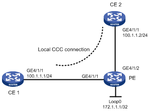
Example for configuring a local CCC connection
Network requirements
As shown in Figure 3, the CEs are connected to the PE through GigabitEthernet interfaces.
Create a local CCC connection between CE 1 and CE 2.
|
|
NOTE: · Because a local CCC connection is bidirectional, one is enough. · The PE interfaces connecting the CEs require no IP addresses. |
Configuration procedure
1. Configure CE 1.
<Sysname> system-view
[Sysname] sysname CE1
[CE1] interface GigabitEthernet 4/1/1
[CE1-GigabitEthernet4/1/1] ip address 100.1.1.1 24
2. Configure the PE.
# Configure the LSR ID and enable MPLS globally.
<Sysname> system-view
[Sysname] sysname PE
[PE] interface loopback 0
[PE-LoopBack0] ip address 172.1.1.1 32
[PE-LoopBack0] quit
[PE] mpls lsr-id 172.1.1.1
[PE] mpls
[PE-mpls] quit
# Enable L2VPN and MPLS L2VPN.
[PE] l2vpn
[PE-l2vpn] mpls l2vpn
[PE-l2vpn] quit
# Configure interface GigabitEthernet 4/1/1.
[PE] interface GigabitEthernet 4/1/1
[PE-GigabitEthernet4/1/1] quit
# Configure interface GigabitEthernet 4/1/2.
[PE] interface GigabitEthernet 4/1/2
[PE-GigabitEthernet 4/1/2] quit
# Create a local connection between CE 1 and CE 2.
[PE] ccc ce1-ce2 interface GigabitEthernet 4/1/1 out-interface GigabitEthernet 4/1/2
3. Configure CE 2.
<Sysname> system-view
[Sysname] sysname CE2
[CE2] interface GigabitEthernet 4/1/1
[CE2-GigabitEthernet4/1/1] ip address 100.1.1.2 24
4. Verify your configuration.
# Display CCC connection information on the PE. The output shows that a local CCC connection has been established.
[PE] display ccc
Total ccc vc : 1
Local ccc vc : 1, 1 up
Remote ccc vc : 0, 0 up
***Name : ce1-ce2
Type : local
State : up
Intf1 : GigabitEthernet4/1/1 (up)
Intf2 : GigabitEthernet4/1/2 (up)
# Ping CE 2 from CE 1. The output shows that CE 1 and CE 2 can ping each other.
[CE1] ping 100.1.1.2
PING 100.1.1.2: 56 data bytes, press CTRL_C to break
Reply from 100.1.1.2: bytes=56 Sequence=1 ttl=255 time=180 ms
Reply from 100.1.1.2: bytes=56 Sequence=2 ttl=255 time=60 ms
Reply from 100.1.1.2: bytes=56 Sequence=3 ttl=255 time=10 ms
Reply from 100.1.1.2: bytes=56 Sequence=4 ttl=255 time=70 ms
Reply from 100.1.1.2: bytes=56 Sequence=5 ttl=255 time=60 ms
--- 100.1.1.2 ping statistics ---
5 packet(s) transmitted
5 packet(s) received
0.00% packet loss
round-trip min/avg/max = 10/76/180 ms
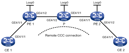
Example for configuring a remote CCC connection
Network requirements
As shown in Figure 4, the CEs are connected to the PEs through GigabitEthernet interfaces.
Create a remote CCC connection between CE 1 and CE 2.
The main steps for configuring a CCC remote connection are:
1. Create a remote CCC connection on the PEs. No static LSP is required on the PEs.
2. Enable MPLS L2VPN on the PEs. You do not need to enable MPLS L2VPN on the P router.
3. Configure two static LSPs on the P router for packets to be transferred in both directions.
|
Device |
Interface |
IP address |
Device |
Interface |
IP address |
|
CE 1 |
GE4/1/1 |
100.1.1.1/24 |
P |
Loop0 |
10.0.0.2/32 |
|
PE 1 |
Loop0 |
10.0.0.1/32 |
|
GE4/1/1 |
10.2.2.2/24 |
|
|
GE4/1/2 |
10.1.1.1/24 |
|
GE4/1/2 |
10.1.1.2/24 |
|
CE 2 |
GE4/1/1 |
100.1.1.2/24 |
PE 2 |
Loop0 |
10.0.0.3/32 |
|
|
|
|
|
GE4/1/1 |
10.2.2.1/24 |
Configuration procedure
1. Configure CE 1.
<Sysname> system-view
[Sysname] sysname CE1
[CE1] interface GigabitEthernet 4/1/1
[CE1-GigabitEthernet4/1/1] ip address 100.1.1.1 24
2. Configure PE 1.
# Configure the LSR ID and enable MPLS globally.
<Sysname> system-view
[Sysname] sysname PE1
[PE1] interface loopback 0
[PE1-LoopBack0] ip address 10.0.0.1 32
[PE1-LoopBack0] quit
[PE1] mpls lsr-id 10.0.0.1
[PE1] mpls
[PE1-mpls] quit
# Enable L2VPN and MPLS L2VPN.
[PE1] l2vpn
[PE1-l2vpn] mpls l2vpn
[PE1-l2vpn] quit
# Configure interface GigabitEthernet 4/1/1.
[PE1] interface GigabitEthernet 4/1/1
[PE1-GigabitEthernet4/1/1] quit
# Configure interface GigabitEthernet 4/1/2, and enable MPLS.
[PE1] interface GigabitEthernet 4/1/2
[PE1-GigabitEthernet4/1/2] ip address 10.1.1.1 24
[PE1-GigabitEthernet4/1/2] mpls
[PE1-GigabitEthernet4/1/2] quit
# Create a remote connection from CE 1 to CE 2, using the interface connecting CE 1 as the incoming interface and the interface connecting the P router as the outgoing interface, setting the incoming label to 100 and the outgoing label to 200.
[PE1] ccc ce1-ce2 interface GigabitEthernet 4/1/1 in-label 100 out-label 200 nexthop 10.1.1.2
3. Configure the P router.
# Configure the LSR ID and enable MPLS globally.
<Sysname> system-view
[Sysname] sysname P
[P] interface loopback 0
[P-LoopBack0] ip address 10.0.0.2 32
[P-LoopBack0] quit
[P] mpls lsr-id 10.0.0.2
[P] mpls
[P-mpls] quit
# Configure interface GigabitEthernet 4/1/2, and enable MPLS.
[P] interface GigabitEthernet 4/1/2
[P-GigabitEthernet4/1/2] ip address 10.1.1.2 24
[P-GigabitEthernet4/1/2] mpls
[P-GigabitEthernet4/1/2] quit
# Configure interface GigabitEthernet 4/1/1, and enable MPLS.
[P] interface GigabitEthernet 4/1/1
[P-GigabitEthernet4/1/1] ip address 10.2.2.2 24
[P-GigabitEthernet4/1/1] mpls
[P-GigabitEthernet4/1/1] quit
# Create a static LSP for forwarding packets from PE 1 to PE 2.
[P] static-lsp transit pe1_pe2 incoming-interface GigabitEthernet 4/1/2 in-label 200 nexthop 10.2.2.1 out-label 201
# Create a static LSP for forwarding packets from PE 2 to PE 1.
[P] static-lsp transit pe2_pe1 incoming-interface GigabitEthernet 4/1/1 in-label 101 nexthop 10.1.1.1 out-label 100
4. Configure PE 2.
# Configure the LSR ID and enable MPLS globally.
<Sysname> system-view
[Sysname] sysname PE2
[PE2] interface loopback 0
[PE2-LoopBack0] ip address 10.0.0.3 32
[PE2-LoopBack0] quit
[PE2] mpls lsr-id 10.0.0.3
[PE2] mpls
[PE2-mpls] quit
# Enable L2VPN and MPLS L2VPN.
[PE2] l2vpn
[PE2-l2vpn] mpls l2vpn
[PE2-l2vpn] quit
# Configure interface GigabitEthernet 4/1/2.
[PE2] interface GigabitEthernet 4/1/2
[PE2-GigabitEthernet4/1/2] quit
# Configure interface GigabitEthernet 4/1/1 and enable MPLS.
[PE2] interface GigabitEthernet 4/1/1
[PE2-GigabitEthernet4/1/1] ip address 10.2.2.1 24
[PE2-GigabitEthernet4/1/1] mpls
[PE2-GigabitEthernet4/1/1] quit
# Create a remote connection from CE 2 to CE 1, using the interface connecting CE 2 as the incoming interface and the interface connecting the P router as the outgoing interface, setting the incoming label to 201 and the outgoing label to 101.
[PE2] ccc ce2-ce1 interface GigabitEthernet 4/1/2 in-label 201 out-label 101 nexthop 10.2.2.2
5. Configure CE 2.
<Sysname> system-view
[Sysname] sysname CE2
[CE2] interface GigabitEthernet 4/1/1
[CE2-GigabitEthernet4/1/1] ip address 100.1.1.2 24
6. Verify your configuration.
# Display CCC connection information on PE 1. The output shows that a remote CCC connection has been established.
[PE] display ccc
Total ccc vc : 1
Local ccc vc : 0, 0 up
Remote ccc vc : 1, 1 up
***Name : ce1-ce2
Type : remote
State : up
Intf : GigabitEthernet4/1/2 (up)
In-label : 201
Out-label : 101
nexthop : 10.2.2.2 (up)
# Ping CE 2 from CE 1. The output shows that CE 1 and CE 2 can ping each other.
[CE1] ping 100.1.1.2
PING 100.1.1.2: 56 data bytes, press CTRL_C to break
Reply from 100.1.1.2: bytes=56 Sequence=1 ttl=255 time=180 ms
Reply from 100.1.1.2: bytes=56 Sequence=2 ttl=255 time=60 ms
Reply from 100.1.1.2: bytes=56 Sequence=3 ttl=255 time=10 ms
Reply from 100.1.1.2: bytes=56 Sequence=4 ttl=255 time=70 ms
Reply from 100.1.1.2: bytes=56 Sequence=5 ttl=255 time=60 ms
--- 100.1.1.2 ping statistics ---
5 packet(s) transmitted
5 packet(s) received
0.00% packet loss
round-trip min/avg/max = 10/76/180 ms
Example for configuring SVC MPLS L2VPN
Network requirements
As shown in Figure 5, the CEs are connected to PEs through GigabitEthernet interfaces.
Establish an SVC MPLS L2VPN between CE 1 and CE 2.
|
Device |
Interface |
IP address |
Device |
Interface |
IP address |
|
CE 1 |
GE4/1/1 |
100.1.1.1/24 |
P |
Loop0 |
192.4.4.4/32 |
|
PE 1 |
Loop0 |
192.2.2.2/32 |
|
GE4/1/1 |
10.2.2.2/24 |
|
|
GE4/1/2 |
10.1.1.1/24 |
|
GE4/1/2 |
10.1.1.2/24 |
|
CE 2 |
GE4/1/1 |
100.1.1.2/24 |
PE 2 |
Loop0 |
192.3.3.3/32 |
|
|
|
|
|
GE4/1/1 |
10.2.2.1/24 |
Configuration procedure
The main steps are the following two:
· Configure MPLS basic forwarding capability on the PEs and P router. This includes configuring the LSR ID, enabling MPLS and LDP, and running IGP (OSPF in this example) between PE 1, the P router, and PE 2 to establish LSPs.
· Establish an SVC MPLS L2VPN connection. This includes enabling MPLS L2VPN on PE 1 and PE 2 and establishing an SVC connection and specifying the VC labels.
The detailed configuration procedure is as follows:
1. Configure CE 1.
<Sysname> system-view
[Sysname] sysname CE1
[CE1] interface GigabitEthernet 4/1/1
[CE1-GigabitEthernet4/1/1] ip address 100.1.1.1 24
2. Configure PE 1.
# Configure the LSR ID and enable MPLS globally.
<Sysname> system-view
[Sysname] sysname PE1
[PE1] interface loopback 0
[PE1-LoopBack0] ip address 192.2.2.2 32
[PE1-LoopBack0] quit
[PE1] mpls lsr-id 192.2.2.2
[PE1] mpls
# Configure the LSP establishment triggering policy.
[PE1-mpls] lsp-trigger all
[PE1-mpls] quit
# Enable L2VPN and MPLS L2VPN.
[PE1] l2vpn
[PE1-l2vpn] mpls l2vpn
[PE1-l2vpn] quit
# Enable LDP globally.
[PE1] mpls ldp
[PE1-mpls-ldp] quit
# Configure the interface for connecting to the P router, namely GigabitEthernet 4/1/2, and enable LDP on the interface.
[PE1] interface GigabitEthernet 4/1/2
[PE1-GigabitEthernet4/1/2] ip address 10.1.1.1 24
[PE1-GigabitEthernet4/1/2] mpls
[PE1-GigabitEthernet4/1/2] mpls ldp
[PE1-GigabitEthernet4/1/2] quit
# Configure OSPF on PE 1 for establishing LSPs.
[PE1] ospf
[PE1-ospf-1] area 0
[PE1-ospf-1-area-0.0.0.0] network 10.1.1.1 0.0.0.255
[PE1-ospf-1-area-0.0.0.0] network 192.2.2.2 0.0.0.0
[PE1-ospf-1-area-0.0.0.0] quit
[PE1-ospf-1] quit
# On the interface connecting CE 1, namely GigabitEthernet 4/1/1, create an SVC MPLS L2VPN connection. The interface requires no IP address.
[PE1] interface GigabitEthernet 4/1/1
[PE1-GigabitEthernet4/1/1] mpls static-l2vc destination 192.3.3.3 transmit-vpn-label 100 receive-vpn-label 200
[PE1-GigabitEthernet4/1/1] quit
3. Configure the P router.
# Configure the LSR ID and enable MPLS globally.
<Sysname> system-view
[Sysname] sysname P
[P] interface loopback 0
[P-LoopBack0] ip address 192.4.4.4 32
[P-LoopBack0] quit
[P] mpls lsr-id 192.4.4.4
[P] mpls
# Enable LDP globally.
[P] mpls ldp
[P-mpls-ldp] quit
# Configure the interface connected with PE 1, namely GigabitEthernet 4/1/2, and enable LDP on the interface.
[P] interface GigabitEthernet 4/1/2
[P-GigabitEthernet4/1/2] ip address 10.1.1.2 24
[P-GigabitEthernet4/1/2] mpls
[P-GigabitEthernet4/1/2] mpls ldp
[P-GigabitEthernet4/1/2] quit
# Configure the interface connected with PE 2, namely GigabitEthernet 4/1/1, and enable LDP on the interface.
[P] interface GigabitEthernet 4/1/1
[P-GigabitEthernet4/1/1] ip address 10.2.2.2 24
[P-GigabitEthernet4/1/1] mpls
[P-GigabitEthernet4/1/1] mpls ldp
[P-GigabitEthernet4/1/1] quit
# Configure OSPF on the P router for establishing LSPs.
[P] ospf
[P-ospf-1] area 0
[P-ospf-1-area-0.0.0.0] network 10.1.1.2 0.0.0.255
[P-ospf-1-area-0.0.0.0] network 10.2.2.2 0.0.0.255
[P-ospf-1-area-0.0.0.0] network 192.4.4.4 0.0.0.0
[P-ospf-1-area-0.0.0.0] quit
[P-ospf-1] quit
4. Configure PE 2.
# Configure the LSR ID and enable MPLS globally.
<Sysname> system-view
[Sysname] sysname PE2
[PE2] interface loopback 0
[PE2-LoopBack0] ip address 192.3.3.3 32
[PE2-LoopBack0] quit
[PE2] mpls lsr-id 192.3.3.3
[PE2] mpls
# Configure the LSP establishment triggering policy.
[PE2-mpls] lsp-trigger all
[PE2-mpls] quit
# Enable L2VPN and MPLS L2VPN.
[PE2] l2vpn
[PE2-l2vpn] mpls l2vpn
[PE2-l2vpn] quit
# Enable LDP globally.
[PE2] mpls ldp
[PE2-mpls-ldp] quit
# Configure the interface connected with the P router, namely GigabitEthernet4/1/1, and enable LDP on the interface.
[PE2] interface GigabitEthernet 4/1/1
[PE2-GigabitEthernet4/1/1] ip address 10.2.2.1 24
[PE2-GigabitEthernet4/1/1] mpls
[PE2-GigabitEthernet4/1/1] mpls ldp
[PE2-GigabitEthernet4/1/1] quit
# Configure OSPF on PE 2 for establishing LSPs.
[PE2] ospf
[PE2-ospf-1] area 0
[PE2-ospf-1-area-0.0.0.0] network 10.2.2.1 0.0.0.255
[PE2-ospf-1-area-0.0.0.0] network 192.3.3.3 0.0.0.0
[PE2-ospf-1-area-0.0.0.0] quit
[PE2-ospf-1] quit
# On the interface connecting CE 2, namely GigabitEthernet 4/1/2, create an SVC MPLS L2VPN connection. The interface requires no IP address.
[PE2] interface GigabitEthernet 4/1/2
[PE2-GigabitEthernet4/1/2] mpls static-l2vc destination 192.2.2.2 transmit-vpn-label 200 receive-vpn-label 100
[PE2-GigabitEthernet4/1/2] quit
5. Configure CE 2.
<Sysname> system-view
[Sysname] sysname CE2
[CE2] interface GigabitEthernet 4/1/1
[CE2-GigabitEthernet4/1/1] ip address 100.1.1.2 24
6. Verify your configuration.
# Display SVC L2VPN connection information on PE 1 or PE 2. The output shows that an L2VPN connection has been established.
Display SVC L2VPN connection information on PE 1:
[PE1] display mpls static-l2vc
Total connections: 1, 1 up, 0 down
ce-intf state destination tr-label rcv-label tnl-policy
GigabitEthernet4/1/1 up 192.3.3.3 100 200 default
Display SVC L2VPN connection information on PE 2:
[PE2] display mpls static-l2vc
Total connections: 1, 1 up, 0 down
ce-intf state destination tr-label rcv-label tnl-policy
GigabitEthernet4/1/2 up 192.2.2.2 200 100 default
# Ping CE 2 from CE 1. The output shows that CE 1 and CE 2 can ping each other.
[CE1] ping 100.1.1.2
PING 100.1.1.2: 56 data bytes, press CTRL_C to break
Reply from 100.1.1.2: bytes=56 Sequence=1 ttl=255 time=150 ms
Reply from 100.1.1.2: bytes=56 Sequence=2 ttl=255 time=130 ms
Reply from 100.1.1.2: bytes=56 Sequence=3 ttl=255 time=130 ms
Reply from 100.1.1.2: bytes=56 Sequence=4 ttl=255 time=140 ms
Reply from 100.1.1.2: bytes=56 Sequence=5 ttl=255 time=80 ms
--- 100.1.1.2 ping statistics ---
5 packet(s) transmitted
5 packet(s) received
0.00% packet loss
round-trip min/avg/max = 80/126/150 ms
Example for configuring Martini MPLS L2VPN
Network requirements
As shown in Figure 6, the CEs are connected to PEs through GigabitEthernet interfaces.
Establish a Martini MPLS L2VPN between CE 1 and CE 2.
|
Device |
Interface |
IP address |
Device |
Interface |
IP address |
|
CE 1 |
GE4/1/1 |
100.1.1.1/24 |
P |
Loop0 |
192.4.4.4/32 |
|
PE 1 |
Loop0 |
192.2.2.2/32 |
|
GE4/1/1 |
10.1.1.2/24 |
|
|
GE4/1/2 |
10.1.1.1/24 |
|
GE4/1/2 |
10.2.2.2/24 |
|
CE 2 |
GE4/1/1 |
100.1.1.2/24 |
PE 2 |
Loop0 |
192.3.3.3/32 |
|
|
|
|
|
GE4/1/2 |
10.2.2.1/24 |
Configuration procedure
1. Configure CE 1.
<Sysname> system-view
[Sysname] sysname CE1
[CE1] interface GigabitEthernet4/1/1
[CE1-GigabitEthernet4/1/1] ip address 100.1.1.1 24
2. Configure PE 1.
# Configure the LSR ID and enable MPLS globally.
<Sysname> system-view
[Sysname] sysname PE1
[PE1] interface loopback 0
[PE1-LoopBack0] ip address 192.2.2.2 32
[PE1-LoopBack0] quit
[PE1] mpls lsr-id 192.2.2.2
[PE1] mpls
# Configure the LSP establishment triggering policy.
[PE1-mpls] lsp-trigger all
[PE1-mpls] quit
# Enable L2VPN and MPLS L2VPN.
[PE1] l2vpn
[PE1-l2vpn] mpls l2vpn
[PE1-l2vpn] quit
# Enable LDP globally.
[PE1] mpls ldp
[PE1-mpls-ldp] quit
# Configure the peer relationship with PE 2 so that the LDP remote session can be established between them.
[PE1] mpls ldp remote-peer 1
[PE1-mpls-ldp-remote-1] remote-ip 192.3.3.3
[PE1-mpls-ldp-remote-1] quit
# Configure the interface connected with the P router, namely GigabitEthernet 4/1/2, and enable LDP on the interface.
[PE1] interface GigabitEthernet4/1/2
[PE1-GigabitEthernet4/1/2] ip address 10.1.1.1 24
[PE1-GigabitEthernet4/1/2] mpls
[PE1-GigabitEthernet4/1/2] mpls ldp
[PE1-GigabitEthernet4/1/2] quit
# Configure OSPF on PE 1 for establishing LSPs.
[PE1] ospf
[PE1-ospf-1] area 0
[PE1-ospf-1-area-0.0.0.0] network 10.1.1.1 0.0.0.255
[PE1-ospf-1-area-0.0.0.0] network 192.2.2.2 0.0.0.0
[PE1-ospf-1-area-0.0.0.0] quit
[PE1-ospf-1] quit
# On the interface connecting CE 1, namely GigabitEthernet 4/1/1, create a Martini MPLS L2VPN connection. The interface requires no IP address.
[PE1] interface GigabitEthernet4/1/1
[PE1-GigabitEthernet4/1/1] mpls l2vc 192.3.3.3 101
[PE1-GigabitEthernet4/1/1] quit
3. Configure the P router.
# Configure the LSR ID and enable MPLS globally.
<Sysname> system-view
[Sysname] sysname P
[P] interface loopback 0
[P-LoopBack0] ip address 192.4.4.4 32
[P-LoopBack0] quit
[P] mpls lsr-id 192.4.4.4
[P] mpls
# Enable LDP globally.
[P] mpls ldp
[P-mpls-ldp] quit
# Configure the interface connected with PE 1, namely GigabitEthernet 4/1/1, and enable LDP on the interface.
[P] interface GigabitEthernet4/1/1
[P-GigabitEthernet4/1/1] ip address 10.1.1.2 24
[P-GigabitEthernet4/1/1] mpls
[P-GigabitEthernet4/1/1] mpls ldp
[P-GigabitEthernet4/1/1] quit
# Configure the interface connected with PE 2, namely GigabitEthernet 4/1/2, and enable LDP on the interface.
[P] interface GigabitEthernet4/1/2
[P-GigabitEthernet4/1/2] ip address 10.2.2.2 24
[P-GigabitEthernet4/1/2] mpls
[P-GigabitEthernet4/1/2] mpls ldp
[P-GigabitEthernet4/1/2] quit
# Configure OSPF on the P router for establishing LSPs.
[P] ospf
[P-ospf-1] area 0
[P-ospf-1-area-0.0.0.0] network 10.1.1.2 0.0.0.255
[P-ospf-1-area-0.0.0.0] network 10.2.2.2 0.0.0.255
[P-ospf-1-area-0.0.0.0] network 192.4.4.4 0.0.0.0
[P-ospf-1-area-0.0.0.0] quit
[P-ospf-1] quit
4. Configure PE 2.
# Configure the LSR ID and enable MPLS globally.
<Sysname> system-view
[Sysname] sysname PE2
[PE2] interface loopback 0
[PE2-LoopBack0] ip address 192.3.3.3 32
[PE2-LoopBack0] quit
[PE2] mpls lsr-id 192.3.3.3
[PE2] mpls
# Configure the LSP establishment triggering policy.
[PE2-mpls] lsp-trigger all
[PE2-mpls] quit
# Enable L2VPN and MPLS L2VPN.
[PE2] l2vpn
[PE2-l2vpn] mpls l2vpn
[PE2-l2vpn] quit
# Enable LDP globally.
[PE2] mpls ldp
[PE2-mpls-ldp] quit
# Configure the peer relationship with PE 1 so that the LDP remote session can be established between them.
[PE2] mpls ldp remote-peer 2
[PE2-mpls-ldp-remote-2] remote-ip 192.2.2.2
[PE2-mpls-ldp-remote-2] quit
# Configure the interface connected with the P router, namely GigabitEthernet 4/1/2, and enable LDP on the interface.
[PE2] interface GigabitEthernet4/1/2
[PE2-GigabitEthernet4/1/2] ip address 10.2.2.1 24
[PE2-GigabitEthernet4/1/2] mpls
[PE2-GigabitEthernet4/1/2] mpls ldp
[PE2-GigabitEthernet4/1/2] quit
# Configure OSPF on PE 2 for establishing LSPs.
[PE2] ospf
[PE2-ospf-1] area 0
[PE2-ospf-1-area-0.0.0.0] network 192.3.3.3 0.0.0.0
[PE2-ospf-1-area-0.0.0.0] network 10.2.2.0 0.0.0.255
[PE2-ospf-1-area-0.0.0.0] quit
[PE2-ospf-1] quit
# On the interface connecting CE 2, namely GigabitEthernet 4/1/1, create a Martini MPLS L2VPN connection. The interface requires no IP address.
[PE2] interface GigabitEthernet4/1/1
[PE2-GigabitEthernet4/1/1] mpls l2vc 192.2.2.2 101
[PE2-GigabitEthernet4/1/1] quit
5. Configure CE 2.
<Sysname> system-view
[Sysname] sysname CE2
[CE2] interface GigabitEthernet4/1/1
[CE2-GigabitEthernet4/1/1] ip address 100.1.1.2 24
6. Verify your configuration.
# Display L2VPN connection information on PE 1. The output shows that an L2VPN connection is established.
[PE1] display mpls l2vc
Total ldp vc : 1 1 up 0 down 0 blocked
Transport Client VC Local Remote
VC ID Intf State VC Label VC Label
101 GE4/1/1 up 1024 1025
# Display the L2VPN connection information on PE 2. The output shows that an L2VPN connection is established on PE 2.
[PE2] display mpls l2vc
Total ldp vc : 1 1 up 0 down 0 blocked
Transport Client VC Local Remote
VC ID Intf State VC Label VC Label
101 GE4/1/1 up 1025 1024
# Ping CE 2 from CE 1. The operation succeeds.
[CE1] ping 100.1.1.2
PING 100.1.1.2: 56 data bytes, press CTRL_C to break
Reply from 100.1.1.2: bytes=56 Sequence=1 ttl=255 time=30 ms
Reply from 100.1.1.2: bytes=56 Sequence=2 ttl=255 time=60 ms
Reply from 100.1.1.2: bytes=56 Sequence=3 ttl=255 time=50 ms
Reply from 100.1.1.2: bytes=56 Sequence=4 ttl=255 time=40 ms
Reply from 100.1.1.2: bytes=56 Sequence=5 ttl=255 time=70 ms
--- 100.1.1.2 ping statistics ---
5 packet(s) transmitted
5 packet(s) received
0.00% packet loss
round-trip min/avg/max = 30/50/70 ms
Example for configuring Kompella MPLS L2VPN
Network requirements
As shown in Figure 7, the CEs are connected to PEs through GigabitEthernet interfaces.
Establish a Kompella MPLS L2VPN between CE 1 and CE 2.
|
Device |
Interface |
IP address |
Device |
Interface |
IP address |
|
CE 1 |
GE4/1/1 |
30.1.1.1/24 |
P |
Loop0 |
2.2.2.9/32 |
|
PE 1 |
Loop0 |
1.1.1.9/32 |
|
GE4/1/1 |
168.1.1.2/24 |
|
|
GE4/1/2 |
168.1.1.1/24 |
|
GE4/1/2 |
169.1.1.1/24 |
|
CE 2 |
GE4/1/1 |
30.1.1.2/24 |
PE 2 |
Loop0 |
3.3.3.9/32 |
|
|
|
|
|
GE4/1/1 |
169.1.1.2/24 |
Configuration procedure
1. Configure an IGP on the MPLS backbone.
This example uses OSPF. (Details not shown)
After configuration, issuing the display ip routing-table command on each LSR, you should see that it has learned the routes to the LSR IDs of the other LSRs. Issuing the display ospf peer command, you should see that OSPF adjacencies have been established and reached the state of Full.
2. Configure basic MPLS and LDP to establish LDP LSPs. (Details not shown)
After configuration, you can issue the display mpls ldp session and display mpls ldp peer commands to view the LDP sessions and peer relationship established, or the display mpls lsp command to view the LSPs established.
3. Configure BGP L2VPN capability.
# Configure PE 1.
<Sysname> system-view
[Sysname] sysname PE1
[PE1] l2vpn
[PE1-l2vpn] mpls l2vpn
[PE1-l2vpn] quit
[PE1] bgp 100
[PE1-bgp] peer 3.3.3.9 as-number 100
[PE1-bgp] peer 3.3.3.9 connect-interface loopback 0
[PE1-bgp] l2vpn-family
[PE1-bgp-af-l2vpn] policy vpn-target
[PE1-bgp-af-l2vpn] peer 3.3.3.9 enable
[PE1-bgp-af-l2vpn] quit
[PE1-bgp] quit
# Configure PE 2.
<Sysname> system-view
[Sysname] sysname PE2
[PE2] l2vpn
[PE2-l2vpn] mpls l2vpn
[PE2-l2vpn] quit
[PE2] bgp 100
[PE2-bgp] peer 1.1.1.9 as-number 100
[PE2-bgp] peer 1.1.1.9 connect-interface loopback 0
[PE2-bgp] l2vpn-family
[PE2-bgp-af-l2vpn] policy vpn-target
[PE2-bgp-af-l2vpn] peer 1.1.1.9 enable
[PE2-bgp-af-l2vpn] quit
[PE2-bgp] quit
After completing the configurations, issue the display bgp l2vpn peer command on PE 1 and PE 2 to view the peer relationship established between the PEs. The peer state should be Established. Take PE 1 as an example:
[PE1] display bgp l2vpn peer
BGP local router ID : 1.1.1.9
Local AS number : 100
Total number of peers : 1 Peers in established state : 1
Peer V AS MsgRcvd MsgSent OutQ PrefRcv Up/Down State
3.3.3.9 4 100 2 5 0 0 00:01:07 Established
4. Configure the L2VPN and the CE connection.
# Configure PE 1.
[PE1] mpls l2vpn vpn1 encapsulation ethernet
[PE1-mpls-l2vpn-vpn1] route-distinguisher 100:1
[PE1-mpls-l2vpn-vpn1] vpn-target 1:1
[PE1-mpls-l2vpn-vpn1] ce ce1 id 1 range 10
[PE1-mpls-l2vpn-ce-vpn1-ce1] connection ce-offset 2 interface GigabitEthernet4/1/1
[PE1-mpls-l2vpn-ce-vpn1-ce1] quit
[PE1-mpls-l2vpn-vpn1] quit
# Configure PE 2.
[PE2] mpls l2vpn vpn1 encapsulation ethernet
[PE2-mpls-l2vpn-vpn1] route-distinguisher 100:1
[PE2-mpls-l2vpn-vpn1] vpn-target 1:1
[PE2-mpls-l2vpn-vpn1] ce ce2 id 2 range 10
[PE2-mpls-l2vpn-ce-vpn1-ce2] connection ce-offset 1 interface GigabitEthernet4/1/2
[PE2-mpls-l2vpn-ce-vpn1-ce2] quit
[PE2-mpls-l2vpn-vpn1] quit
5. Verify your configuration.
Issue the display mpls l2vpn connection command on the PEs. The output shows that an L2VPN connection is established between the PEs and the connection is up. Take PE 1 as an example:
[PE1] display mpls l2vpn connection
1 total connections,
connections: 1 up, 0 down, 0 local, 1 remote, 0 unknown
VPN name: vpn1,
1 total connections,
connections: 1 up, 0 down, 0 local, 1 remote, 0 unknown
CE name: ce1, id: 1,
Rid type status peer-id route-distinguisher intf
2 rmt up 3.3.3.9 100:1 GigabitEthernet4/1/2
# Ping CE 2 from CE 1. The output shows that CE 1 and CE 2 can ping each other.
[CE1] ping 30.1.1.2
PING 30.1.1.2: 56 data bytes, press CTRL_C to break
Reply from 30.1.1.2: bytes=56 Sequence=1 ttl=255 time=90 ms
Reply from 30.1.1.2: bytes=56 Sequence=2 ttl=255 time=77 ms
Reply from 30.1.1.2: bytes=56 Sequence=3 ttl=255 time=34 ms
Reply from 30.1.1.2: bytes=56 Sequence=4 ttl=255 time=46 ms
Reply from 30.1.1.2: bytes=56 Sequence=5 ttl=255 time=94 ms
--- 30.1.1.2 ping statistics ---
5 packet(s) transmitted
5 packet(s) received
0.00% packet loss
round-trip min/avg/max = 34/68/94 ms
Example for configuring a Kompella local connection
Network requirements
As shown in Figure 8, create a Kompella local connection between CE 1 and CE 2.
Configuration procedure
1. Configure the PE.
# Configure basic MPLS. (Details not shown)
# Configure the L2VPN and the CE connection.
<Sysname> system-view
[Sysname] sysname PE
[PE] l2vpn
[PE-l2vpn] mpls l2vpn
[PE-l2vpn] quit
[PE] mpls l2vpn vpn1 encapsulation ethernet
[PE-mpls-l2vpn-vpn1] route-distinguisher 100:1
[PE-mpls-l2vpn-vpn1] vpn-target 111:1
[PE-mpls-l2vpn-vpn1] ce ce1 id 1
[PE-mpls-l2vpn-ce-vpn1-ce1] connection ce-offset 2 interface GigabitEthernet4/1/1
[PE-mpls-l2vpn-ce-vpn1-ce1] quit
[PE-mpls-l2vpn-vpn1] ce ce2 id 2
[PE-mpls-l2vpn-ce-vpn1-ce2] connection ce-offset 1 interface GigabitEthernet4/1/2
[PE-mpls-l2vpn-vpn1] quit
2. Verify your configuration.
# Issue the display mpls l2vpn connection command on the PE. The output shows that two local L2VPN connections are established and in up state.
[PE] display mpls l2vpn connection
2 total connections,
connections: 2 up, 0 down, 2 local, 0 remote, 0 unknown
VPN name: vpn1,
2 total connections,
connections: 2 up, 0 down, 2 local, 0 remote, 0 unknown
CE name: ce1, id: 1,
Rid type status peer-id route-distinguisher intf
2 loc up --- --- GigabitEthernet4/1/1
CE name: ce2, id: 2,
Rid type status peer-id route-distinguisher intf
1 loc up --- --- GigabitEthernet4/1/2
# Ping CE 2 from CE 1. The output shows that CE 1 and CE 2 can ping each other.
[CE1] ping 30.1.1.2
PING 30.1.1.2: 56 data bytes, press CTRL_C to break
Reply from 30.1.1.2: bytes=56 Sequence=1 ttl=255 time=90 ms
Reply from 30.1.1.2: bytes=56 Sequence=2 ttl=255 time=77 ms
Reply from 30.1.1.2: bytes=56 Sequence=3 ttl=255 time=34 ms
Reply from 30.1.1.2: bytes=56 Sequence=4 ttl=255 time=46 ms
Reply from 30.1.1.2: bytes=56 Sequence=5 ttl=255 time=94 ms
--- 30.1.1.2 ping statistics ---
5 packet(s) transmitted
5 packet(s) received
0.00% packet loss
round-trip min/avg/max = 34/68/94 ms
Troubleshooting MPLS L2VPN
Symptom
After the L2VPN configuration, the peer PEs cannot ping each other. The output of the display mpls l2vc command shows that the VC is down and the remote VC label is invalid.
Analysis
The reason the VC is down may be that the PEs are configured with different encapsulation types.
Solution
· Check whether the local PE and the peer PE are configured with the same encapsulation type. If not, the connection is destined to fail.
· Check whether the PEs are configured with the Remote argument and whether the peer addresses are correctly configured.