- Table of Contents
- Related Documents
-
| Title | Size | Download |
|---|---|---|
| 01-MPLS Basics Configuration | 628.09 KB |
Contents
LSP establishment and label distribution
Establishing dynamic LSPs through LDP
Configuring MPLS LDP capability
Configuring Local LDP session parameters
Configuring remote LDP session parameters
Configuring the policy for triggering LSP establishment
Configuring the label distribution control mode
Configuring LDP loop detection
Configuring LDP MD5 authentication
Configuring LDP label filtering
Managing and optimizing MPLS forwarding
Configuring TTL processing mode at ingress
Sending back ICMP TTL exceeded messages for MPLS TTL expired packets
Setting the interval for reading statistics
Configuring periodic LSP tracert
Displaying and maintaining MPLS
Configuring LDP to establish LSPs dynamically
Configuring BFD for LSP validity check
|
|
NOTE: · For information about VPN, see the chapters “Configuring MPLS L2VPN” and “Configuring MPLS L3VPN.” · For information about MPLS TE, see the chapter “Configuring MPLS TE.” |
MPLS overview
Multiprotocol Label Switching (MPLS) is a new IP backbone technology. It introduces connection-oriented label switching into connectionless IP networks, and seamlessly integrates the flexibility of IP routing and the simplicity of Layer 2 switching.
MPLS is widely used on large-scale networks for it features the following advantages:
· On an MPLS network, devices forward packets according to short- and fixed-length labels, instead of doing Layer 3 header analysis and complicated routing table lookup independently. This is a highly effective and fast data transmission method on backbone networks.
· Residing between the link layer and the network layer, MPLS can work on various link layer protocols (for example, PPP, ATM, frame relay, and Ethernet), provide connection-oriented services for various network layer protocols (for example, IPv4, IPv6, and IPX), and work with mainstream network technologies.
· As MPLS is connection-oriented and supports label stack, it is used in various services, such as VPN, traffic engineering, and QoS.
Basic concepts
FEC
As a forwarding technology based on classification, MPLS groups packets with the same characteristics (such as packets with the same destination or service class) into a class, called a “forwarding equivalence class (FEC)”. Packets of the same FEC are handled in the same way on an MPLS network. The device supports classifying FECs according to the network layer destination addresses of packets.
Label
A label is a short, fixed length identifier for identifying a single FEC. A label is locally significant and must be locally unique.
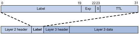
As shown in Figure 1, a label is encapsulated between the Layer 2 header and Layer 3 header of a packet. A label is four bytes in length and consists of the following fields:
· Label—20 bits in length. Label value for identifying a FEC.
· Exp—Three bits in length. Reserved field, usually used for CoS.
· S—One bit in length. MPLS supports multiple levels of labels. This field is used to indicate whether a label is at the bottom of the label stack. 1 indicates that the label is at the bottom of the label stack.
· TTL—Eight bits in length. Like the homonymous IP header field, it is used to prevent loops.
LSR
A label switching router (LSR) is a fundamental component on an MPLS network. LSRs support label distribution and label swapping.
LER
A label edge router (LER) is an LSR that resides at the edge of an MPLS network and is connected to another network.
LSP
A label switched path (LSP) is the path along which packets of a FEC travel through an MPLS network.
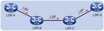
An LSP is a unidirectional path from the ingress of an MPLS network to the egress. On an LSP, in the packet transfer direction, two neighboring LSRs are called the “upstream LSR” and “downstream LSR” respectively. In Figure 2, LSR B is the downstream LSR of LSR A; LSR A is the upstream LSR of LSR B.
LFIB
On an MPLS network, labeled packets are forwarded according to the Label Forwarding Information Base (LFIB), which is like the FIB for IP packet forwarding on an IP network.
Control plane and forwarding plane
An MPLS node consists of two planes, control plane and forwarding plane.
· Control plane—Assigns labels, selects routes, establishes the LFIB, establishes and removes LSPs
· Forwarding plane—Forwards packets according to the LFIB
Structure of the MPLS network
Figure 3 Diagram for the MPLS network structure
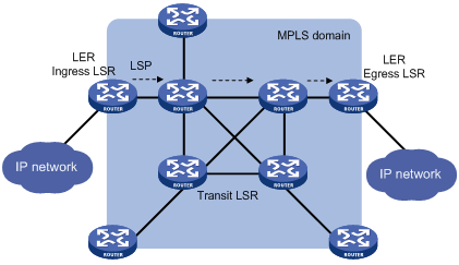
As shown in Figure 3, the element of an MPLS network is LSR. LSRs in the same routing or administrative domain form an MPLS domain.
An MPLS domain consists of the following types of LSRs:
· Ingress LSRs for receiving and labeling packets coming into the MPLS domain.
· Transit LSRs for forwarding packets along LSPs to their egress LERs according to the labels.
· Egress LSRs for removing labels from packets and IP forwarding the packets to their destination networks.
In other words, transit LSRs perform MPLS forwarding based on labels of packets, and the ingress and egress LSRs deal with the switchover between MPLS and IP forwarding.
LSP establishment and label distribution
LSP establishment
Establishing LSPs is to bind FECs with labels on each LSR involved and notify its adjacent LSRs of the bindings, so as to establish the LFIB on each LSR. LSPs can be established through manual configuration, or be established dynamically through label distribution protocols.
1. Establishing a static LSP through manual configuration
To establish a static LSP, you need to assign a label to the FEC on each LSR along the packet forwarding path. Establishment of static LSPs consumes fewer resources than dynamic LSP establishment. However, static LSPs cannot adapt to network topology changes. Therefore, static LSPs are suitable for small-scale networks with simple, stable topologies.
2. Establishing an LSP through a label distribution protocol
Label distribution protocols are MPLS signaling protocols. They can classify FECs, distribute labels, and establish and maintain LSPs. Label distribution protocols include protocols designed specifically for label distribution, such as the Label Distribution Protocol (LDP), and protocols extended to support label distribution, such as BGP and RSVP-TE.
This document discusses LDP only. For more information about LDP, see “LDP.”
|
|
NOTE: In this document, the term label distribution protocols represents all protocols for label distribution, and the term LDP refers to the Label Distribution Protocol defined in RFC 5036. |
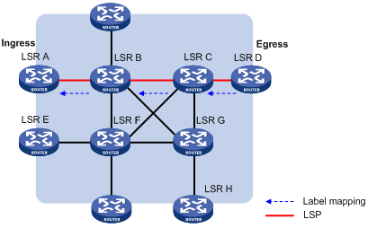
As shown in Figure 4, a dynamic LSP is established in the following procedure:
A downstream LSR classifies FECs according to destination addresses, assigns a label to a FEC, and distributes the FEC-label binding to its upstream LSR, which then establishes an LFIB entry for the FEC according to the binding information. After all LSRs along the packet forwarding path establish a LFIB entry for the FEC, an LSP is established for packets of this FEC.
Figure 4 Process of dynamic LSP establishment
Label distribution and management
An LSR informs its upstream LSRs of labels assigned to FECs through label advertisement. According to the label distribution condition and order, the label advertisement mode can be downstream unsolicited (DU) and downstream on demand (DoD), and the label distribution control mode can be independent or ordered.
MPLS has two label retention modes—liberal and conservative—to manage the received label bindings that are not useful at the moment.
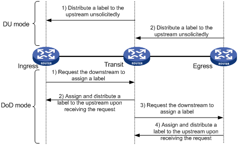
Figure 5 Label advertisement modes
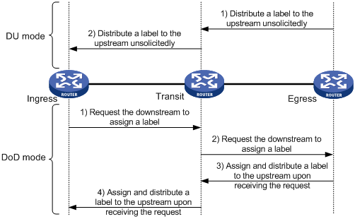
Figure 5 shows the two label advertisement modes, DU and DoD.
· In DU mode, an LSR assigns a label to a FEC and then distributes the FEC-label binding to its upstream LSR unsolicitedly.
· In DoD mode, an LSR assigns a label to a FEC and distributes the FEC-label binding to its upstream LSR only when it receives a label request from the upstream LSR.
|
|
NOTE: · The device supports only the DU mode. · An upstream LSR and its downstream LSR for an FEC must use the same label advertisement mode; otherwise, no LSP can be established normally. |
2. Label distribution control modes
Two label distribution control modes are available: independent and ordered.
¡ In independent mode, an LSR can distribute label bindings upstream at anytime. This means that an LSR may have distributed a label binding to its upstream LSR before it receives a binding from its downstream LSR. As shown in Figure 6, in independent label distribution control mode, if the label advertisement mode is DU, an LSR will assign labels to its upstream even if it has not obtained labels from its downstream; if the label advertisement mode is DoD, the LSR distributes a label to its upstream as long as it receives a label request from the upstream.
Figure 6 Independent label distribution control mode
¡ In ordered mode, an LSR distributes its label binding for a FEC upstream only when it receives a label binding for the FEC from its downstream or it is the egress of the FEC. In Figure 5, label distribution control is in ordered mode. In this case, if the label advertisement mode is DU, an LSR will distribute a label upstream only when it receives a label binding for the FEC from its downstream; if the label advertisement mode is DoD, after an LSR (Transit in this example) receives a label request from its upstream (Ingress), the LSR (Transit) sends a label request to its downstream (Egress). Then, after the LSR (Transit) receives the label binding from its downstream (Egress), it distributes a label binding to the upstream (Ingress).
3. Label retention modes
Two label retention modes are available: liberal and conservative.
¡ In liberal mode, an LSR keeps any received label binding regardless of whether the binding is from its next hop for the FEC or not. This allows for quicker adaptation to route changes but will waste label resources as LSRs need to keep extra labels.
¡ In conservative mode, an LSR keeps only label bindings that are from its next hops for the FECs. This allows LSRs to maintain fewer labels but makes LSRs slower in adapting to route changes.
|
|
NOTE: The router supports only the liberal mode. |
MPLS forwarding
LFIB
An LFIB comprises the following parts:
· Next Hop Label Forwarding Entry (NHLFE)—Describes the label operation to be performed. It is used when forwarding MPLS packets.
· FEC to NHLFE (FTN) map—FTN maps each FEC to a set of NHLFEs at the ingress LSR. The FTN map is used for forwarding unlabeled packets that need MPLS forwarding. When an LSR receives an unlabeled packet, it looks for the corresponding FIB entry. If the Token value of the FIB entry is not Invalid, the packet needs to be forwarded through MPLS. The LSR will then look for the corresponding NHLFE entry according to Token value to determine the label operation to be performed.
· Incoming Label Map (ILM)—ILM maps each incoming label to a set of NHLFEs. It is used when forwarding labeled packets. When an LSR receives a labeled packet, it looks for the corresponding ILM entry. If the Token value of the ILM entry is not null, the LSR will look for the corresponding NHLFE entry to determine the label operation to be performed.
|
|
NOTE: FTN and ILM are associated with NHLFE through Token. |
MPLS data forwarding
Figure 7 MPLS forwarding process diagram
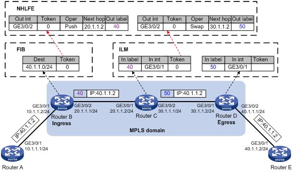
As shown in Figure 7, in an MPLS domain, a packet is forwarded in the following procedure:
1. The ingress (Router B) receives a packet carrying no label. Router B determines the FEC of the packet according to the destination address, and searches the FIB table for the Token value. As the Token value is not Invalid, Router B looks for the corresponding NHLFE entry of the Token value. According to the NHLFE entry, Router B pushes label 40 to the packet, and then forwards the labeled packet to the next hop LSR (Router C) through the outgoing interface (GE3/0/2).
2. Upon receiving the labeled packet, Router C looks for the ILM entry according to the label (40) to get the Token value. As the Token value is not null, Router C looks for the corresponding NHLFE entry of the Token value. According to the NHLFE entry, Router C swaps the original label with label 50, and then forwards the labeled packet to the next hop LSR (Router D) through the outgoing interface (GE3/0/2).
3. Upon receiving the labeled packet, Router D (the egress) looks for the ILM entry according to the label (50) to get the Token value. As the Token is null, Router D removes the label from the packet. If the ILM entry records the outgoing interface, Router D forwards the packet through the outgoing interface; if no outgoing interface is recorded, router D forwards the packet according to the IP header of the packet.
PHP
In an MPLS network, when an egress node receives a labeled packet, it looks up the LFIB, pops the label of the packet, and then performs the next level label forwarding or performs IP forwarding. An egress node needs to do forwarding table lookup twice to forward a packet: looks up the LFIB twice, or looks up the LFIB once and the FIB once.
In this case, the penultimate hop popping (PHP) feature can pop the label at the penultimate node, relieving the egress of the label operation burden and improving the packet processing capability of the MPLS network.
PHP is configurable on the egress node. The label assigned by a PHP-capable egress node to the penultimate hop can be one of the following:
· A label value of 0 represents an IPv4 explicit null label. An egress assigns an IPv4 explicit null label to a FEC and advertises the FEC-label binding to the upstream LSR. When forwarding an MPLS packet, the upstream LSR substitutes the label at the stack top with the explicit null label and then sends the packet to the egress. When the egress receives the packet, which carries a label of 0, it does not look up for the LFIB entry but pops the label stack directly and performs IPv4 forwarding.
· A label value of 3 represents an implicit null label and never appears in the label stack. When an LSR finds that it is assigned an implicit null label, it directly performs a pop operation, rather than substitutes the implicit null label for the original label at the stack top. Then, it forwards the packet to the egress. The egress thus can directly perform the next level forwarding upon receiving the packet.
LDP
The LDP protocol is used to establish LSPs dynamically. Using LDP, LSRs can map network layer routing information to data link layer switching paths.
Basic concepts of LDP
· LDP session
LDP sessions are established between LSRs based on TCP connections and used to exchange messages for label binding, label releasing, and error notification.
· LDP peer
Two LSRs with an LDP session established between them and using LDP to exchange FEC-label bindings are LDP peers.
LDP message type
LDP messages fall into the following types:
· Discovery messages—Declare and maintain the presence of LSRs on a network.
· Session messages—Establish, maintain, and terminate sessions between LDP peers.
· Advertisement messages—Create, alter, or remove FEC-label bindings.
· Notification messages—Provide advisory information and to notify errors.
For reliable transport of LDP messages, TCP is used for LDP session messages, advertisement messages, and notification messages. UDP is used only for discovery messages.
LDP operation
LDP goes through four phases in operation:
1. Discovery
Every LSR that wants to establish LDP sessions sends Hello messages periodically to notify neighboring LSRs of its presence. In this way, LSRs can automatically discover their LDP peers. LDP provides the following discovery mechanisms:
¡ Basic discovery mechanism—Discovers local LDP peers, or, LSRs directly connected at the link layer. In this mechanism, an LSR periodically sends LDP link hello messages to multicast address 224.0.0.2, or, all routers on the subnet, so that all LSRs directly connected at the link layer can discover this LSR.
¡ Extended discovery mechanism—Discovers remote LDP peers, or, LSRs not directly connected at the link layer. In this mechanism, an LSR periodically sends LDP targeted Hello messages to a given IP address so that the LSR with the IP address can discover the LDP peer.
2. Session establishment and maintenance
After an LSR finds an LDP peer, the LSRs go through the following steps to establish a session:
a. Establish a TCP connection between them.
b. Initialize negotiation of session parameters such as the LDP version, label advertisement mode, and Keepalive interval.
After a session is established between them, the two LDP peers send Hello messages and Keepalive messages to maintain the session.
3. LSP establishment and maintenance
LDP sends label requests and label binding messages, so as to advertise label bindings between LDP peers and thereby establish LSPs.
For the LSP establishment process, see “LSP establishment and label distribution.”
4. Session termination
An LSR terminates its LDP session with an LDP peer in the following cases:
¡ All Hello adjacencies are deleted between the two peers
LDP peers periodically send Hello messages to indicate that they intend to keep the Hello adjacency. If an LSR does not receive any Hello message from a peer before the Hello timer expires, it deletes the Hello adjacency with this peer. An LDP session has one or more Hello adjacencies. When the last Hello adjacency for the session is deleted, the LSR will send a Notification message to terminate the LDP session.
¡ Loss of session connectivity
An LSR determines the integrity of an LDP session according to the LDP PDU (which carries one or more LDP messages) transmitted on the session. Before the Keepalive timer times out, if two LDP peers have no information to exchange, they can send Keepalive messages to each other to maintain the LDP session. If an LSR does not receive any LDP PDU from its peer during a Keepalive interval, it closes the TCP connection and terminates the LDP session.
¡ Receiving a shutdown message from the peer
An LSR can also send a Shutdown message to its LDP peer to terminate the LDP session. Therefore, when receiving the Shutdown message from an LDP peer, an LSR will terminate the session with the LDP peer.
Protocols
MPLS related protocols include:
· RFC 3031, Multiprotocol Label Switching Architecture
· RFC 3032, MPLS Label Stack Encoding
· RFC 5036, LDP Specification
MPLS configuration task list
Complete the following tasks to configure MPLS:
|
Task |
Remarks |
||
|
Required |
|||
|
Required |
Use either the static or dynamic LSP configuration method |
||
|
Required |
|||
|
Optional |
|||
|
Optional |
|||
|
Optional |
|||
|
Optional |
|||
|
Optional |
|||
|
Optional |
|||
|
Optional |
|||
|
Optional |
|||
|
Optional |
|||
|
Optional |
|||
|
Optional |
|||
|
Optional |
|||
|
Sending back ICMP TTL exceeded messages for MPLS TTL expired packets |
Optional |
||
|
Optional |
|||
|
Optional |
|||
|
Optional |
|||
|
Optional |
|||
|
Optional |
|||
|
Optional |
|||
|
Optional |
|||
|
|
NOTE: These types of interfaces support MPLS capability: Layer 3 Ethernet interface (GE interface and XGE interface), ATM interface, POS interface, Layer 3 aggregate interface, Mp-group interface, MFR interface, tunnel interface, VLAN interface, HDLC interface, and RPR logical interface. |
Enabling the MPLS function
In an MPLS domain, you need to enable MPLS on all routers for MPLS forwarding before you can configure other MPLS features.
Configuration prerequisites
Before you enable MPLS, complete the following tasks:
· Configure link layer protocols to ensure the connectivity at the link layer.
· Assign IP addresses to interfaces, making all neighboring nodes reachable at the network layer.
· Configure static routes or an IGP protocol, ensuring that LSRs can communicate with each other at the network layer.
Configuration procedure
To enable MPLS:
|
Step |
Command |
Remarks |
|
1. Enter system view. |
system-view |
N/A |
|
2. Configure the MPLS LSR ID. |
mpls lsr-id lsr-id |
Not configured by default |
|
3. Enable MPLS globally and enter MPLS view. |
mpls |
Not enabled by default |
|
4. Return to system view. |
quit |
N/A |
|
5. Enter interface view. |
interface interface-type interface-number |
N/A |
|
6. Enable MPLS for the interface. |
mpls |
Not enabled by default |
|
|
NOTE: An MPLS LSR ID is in the format of an IP address and must be unique within an MPLS domain. H3C recommends using the IP address of a loopback interface on an LSR as the MPLS LSR ID. |
Configuring a static LSP
The principle of establishing a static LSP is that the outgoing label of an upstream LSR is the incoming label of its downstream LSR.
Configuration prerequisites
Before you configure a static LSP, complete the following tasks:
· Determine the ingress LSR, transit LSRs, and egress LSR for the static LSP.
· Enable MPLS on all these LSRs.
· Make sure that the ingress LSR has a route to the FEC destination. This is not required on the transit LSRs and egress LSR.
Configuration procedure
To configure a static LSP:
|
Step |
Command |
|
1. Enter system view. |
system-view |
|
2. Configure a static LSP taking the current LSR as the ingress. |
static-lsp ingress lsp-name destination dest-addr { mask | mask-length } { nexthop next-hop-addr | outgoing-interface interface-type interface-number } out-label out-label |
|
3. Configure a static LSP taking the current LSR as a transit LSR. |
static-lsp transit lsp-name incoming-interface interface-type interface-number in-label in-label { nexthop next-hop-addr | outgoing-interface interface-type interface-number } out-label out-label |
|
4. Configure a static LSP taking the current LSR as the egress. |
static-lsp egress lsp-name incoming-interface interface-type interface-number in-label in-label |
|
|
NOTE: · If the outgoing interface specified for a static LSP is a P2MP interface, such as a P2MP ATM subinterface or a P2MP frame relay subinterface, the static LSP cannot be up. · When you configure a static LSP on the ingress LSR, the next hop or outgoing interface specified must be consistent with the next hop or outgoing interface of the optimal route in the routing table. If you configure a static IP route for the LSP, be sure to specify the same next hop or outgoing interface for the static route and the static LSP. · For an ingress or transit LSR, do not specify the public address of an interface on the LSR as the next hop address. · For information about configuring a static IP route, see Layer 3—IP Routing Configuration Guide. |
Establishing dynamic LSPs through LDP
Configuring MPLS LDP capability
To configure MPLS LDP capability:
|
Step |
Command |
Remarks |
|
1. Enter system view. |
system-view |
N/A |
|
2. Enable LDP capability globally and enter MPLS LDP view. |
mpls ldp |
Not enabled by default. |
|
3. Configure the LDP LSR ID. |
lsr-id lsr-id |
Optional. MPLS LSR ID of the LSR by default. |
|
4. Return to system view. |
quit |
N/A |
|
5. Enter interface view. |
interface interface-type interface-number |
N/A |
|
6. Enable LDP capability for the interface. |
mpls ldp |
Not enabled by default. |
|
|
NOTE: · Disabling LDP on an interface terminates all LDP sessions on the interface. As a result, all LSPs using the sessions will be deleted. · Usually, you do not need to configure the LDP LSR ID but use the default, which is the MPLS LSR ID. In some applications that use VPN instances (for example, MPLS L3VPN), however, you need to make sure that different LDP instances have different LDP LSR IDs if the address spaces overlap. Otherwise, the TCP connections cannot be established normally. |
Configuring Local LDP session parameters
LDP sessions established between local LDP peers are referred to as local LDP sessions. To establish a local LDP session:
· Determine the LDP transport addresses of the two peers and make sure that the LDP transport addresses are reachable to each other. This is to establish the TCP connection.
· If there are a many LDP sessions between the two LSRs or the CPU is occupied much, you need to adjust timers to ensure the stability of the LDP sessions.
To configure local LDP session parameters:
|
Step |
Command |
Remarks |
|
1. Enter system view. |
system-view |
N/A |
|
2. Enter interface view. |
interface interface-type interface-number |
N/A |
|
3. Set the link Hello timer. |
mpls ldp timer hello-hold value |
Optional. 15 seconds by default. |
|
4. Set the link Keepalive timer. |
mpls ldp timer keepalive-hold value |
Optional. 45 seconds by default. |
|
5. Configure the LDP transport address. |
mpls ldp transport-address { ip-address | interface } |
Optional. MPLS LSR ID of the LSR by default. |
|
|
CAUTION: If you configure an LDP transport address by specifying an IP address, the specified IP address must be the IP address of an interface on the router. Otherwise, the LDP sessions cannot be established. |
Configuring remote LDP session parameters
LDP sessions established between remote LDP peers are referred to as remote LDP sessions. Remote LDP sessions are mainly used in Martini MPLS L2VPN, Martini VPLS, and MPLS LDP over MPLS TE. For more information about remote session applications, see the chapters “Configuring MPLS L2VPN,” “Configuring VPLS,” and “Configuring MPLS TE.”
To establish a remote LDP session:
· Determine the LDP transport addresses of the two peers and make sure that the LDP transport addresses are reachable to each other. This is to establish the TCP connection.
· If there are a many LDP sessions between the two LSRs or the CPU is occupied much, you need to adjust timers to ensure the stability of the LDP sessions.
To configure remote LDP session parameters:
|
Step |
Command |
Remarks |
|
1. Enter system view. |
system-view |
N/A |
|
2. Create a remote peer entity and enter MPLS LDP remote peer view. |
mpls ldp remote-peer remote-peer-name |
N/A |
|
3. Configure the remote peer IP address. |
remote-ip ip-address |
N/A |
|
4. Configure LDP to advertise prefix-based labels through a remote session. |
prefix-label advertise |
Optional. By default, LDP does not advertise prefix-based labels through a remote session. |
|
5. Set the targeted Hello timer. |
mpls ldp timer hello-hold value |
Optional. 45 seconds by default. |
|
Set the targeted Keepalive timer. |
mpls ldp timer keepalive-hold value |
Optional. 45 seconds by default. |
|
7. Configure the LDP transport address. |
mpls ldp transport-address ip-address |
Optional. MPLS LSR ID of the LSR by default. |
|
|
NOTE: · The IP address specified as the LDP transport address must be the IP address of an interface on the router. · The remote peer IP address to be configured must be different from all existing remote peer IP addresses. · If a local adjacency exists between two peers, no remote adjacency can be established between them. If a remote adjacency exists between two peers, you can configure a local adjacency for them. However, the local adjacency can be established only when the transport address and keepalive settings for the local peer and those for the remote peer match respectively, in which case the remote adjacency will be removed. That is, only one remote session or local session can exist between two LSRs, and the local session takes precedence over the remote session. · By default, LDP does not advertise any prefix-based label mapping message through a remote session, and remote sessions are used only to transfer messages for L2VPNs. For more information about remote session applications, see the Martini MPLS L2VPN configuration in the chapter “Configuring MPLS L2VPN.” · Configuring LDP to advertise prefix-based labels through a remote session is for implementing MPLS LDP over MPLS TE. For information about MPLS LDP over MPLS TE, see the chapter “Configuring MPLS TE.” |
Configuring PHP
To configure PHP:
|
Step |
Command |
Remarks |
|
1. Enter system view. |
system-view |
N/A |
|
2. Enter MPLS view. |
mpls |
N/A |
|
3. Specify the type of the label to be distributed by the egress to the penultimate hop. |
label advertise { explicit-null | implicit-null | non-null } |
Optional. By default, an egress distributes to the penultimate hop an implicit null label. |
|
|
NOTE: · The router supports PHP when it works as a penultimate hop. It can accept the explicit or implicit null label. · When working as the egress, the router cannot distribute a normal label to the penultimate hop (that is, it does not support the non-null type). H3C recommends using a device that supports PHP as the penultimate hop. · For LDP sessions existing before the label advertise command is configured, you need to reset the LDP sessions by using the reset mpls ldp command for the PHP configuration to take effect. · After sessions are established, if you use the label advertise command to change the type of label that the egress should distribute to the penultimate hop, you need to restart the router for the configuration to take effect. |
Configuring the policy for triggering LSP establishment
You can configure an LSP triggering policy on an LSR, so that only routes matching the policy can trigger establishment of LSPs, reducing the number of LSPs to be established on the LSR and avoiding instability of the LSR caused by excessive LSPs.
An LSR supports two types of LSP triggering policies:
· Allowing all routing entries to trigger establishment of LSPs.
· Filtering routing entries by an IP prefix list, so that static and IGP routes denied by the IP prefix list will not trigger LSP establishment. To use this policy, you must create the IP prefix list. For information about IP prefix list configuration, see Layer 3—IP Routing Configuration Guide.
To configure the policy for triggering LSP establishment:
|
Step |
Command |
Remarks |
|
1. Enter system view. |
system-view |
N/A |
|
2. Enter MPLS view. |
mpls |
N/A |
|
3. Configure the LSP establishment triggering policy. |
lsp-trigger [ vpn-instance vpn-instance-name ] { all | ip-prefix prefix-name } |
Optional. By default, only host routes with 32-bit masks can trigger establishment of LSPs. |
|
|
NOTE: · For an LSP to be established, an exactly matching routing entry must exist on the LSR. For example, on an LSR, to establish an LSP to a loopback address with a 32-bit mask, there must be an exactly matching host routing entry on the LSR. · If the vpn-instance vpn-instance-name combination is specified, the command configures an LSP establishment triggering policy for the specified VPN; otherwise, the command configures an LSP establishment triggering policy for the public network routes. |
Configuring the label distribution control mode
With the label re-advertisement function enabled, an LSR periodically looks for FECs not assigned with labels, assigns labels to them if any, and advertises the label-FEC bindings. You can set the label re-advertisement interval as needed.
To configure the LDP label distribution control mode:
|
Step |
Command |
Remarks |
|
1. Enter system view. |
system-view |
N/A |
|
2. Enter MPLS LDP view. |
mpls ldp |
N/A |
|
3. Specify the label distribution control mode. |
label-distribution { independent | ordered } |
Optional. Ordered by default. For LDP sessions existing before the command is configured, you need to reset the LDP sessions for the specified label distribution control mode to take effect. |
|
4. Enable label re-advertisement for DU mode. |
du-readvertise |
Optional. Enabled by default. |
|
5. Set the interval for label re-advertisement in DU mode. |
du-readvertise timer value |
Optional. 30 seconds by default. |
Configuring LDP loop detection
LSPs established in an MPLS domain may be looping. The LDP loop detection mechanism can detect looping LSPs and prevent LDP messages from looping forever.
LDP loop detection can be in either of two modes:
1. Maximum hop count
A label request message or label mapping message carries information about its hop count, which increments by 1 for each hop. When this value reaches the specified limit, LDP considers that a loop is present and terminates the establishment of the LSP.
2. Path vector
A label request message or label mapping message carries path information in the form of path vector list. When such a message reaches an LSR, the LSR checks the path vector list of the message to see whether its MPLS LSR ID is in the list. If not, the LSR will add its LSR ID to the path vector list; if yes, the LSR considers that a loop appears and terminates the establishment of the LSP.
In the path vector mode, you also need to specify the maximum number of hops of an LSP. An LSR will also terminate the establishment of an LSP when the hop count of the path, or the length of the path vector, reaches the specified limit.
To configure LDP loop detection:
|
Step |
Command |
Remarks |
|
1. Enter system view. |
system-view |
N/A |
|
2. Enter MPLS LDP view. |
mpls ldp |
N/A |
|
3. Enable loop detection. |
loop-detect |
Disabled by default. |
|
4. Set the maximum hop count. |
hops-count hop-number |
Optional. 32 by default. |
|
5. Set the maximum path vector length. |
path-vectors pv-number |
Optional 32 by default. |
|
|
NOTE: · The loop detection modes configured on two LDP peers must be the same. Otherwise, the LDP session cannot be established. · To implement loop detection in an MPLS domain, you need to enable loop detection on every LSR in the MPLS domain. · You need to configure loop detection before enabling LDP capability on any interface. · All loop detection configurations take effect for only the LSPs established after the configurations. Changing the loop detection configurations does not affect existing LSPs. You can execute the reset mpls ldp command in user view, so that the loop detection configurations also take effect for existing LSPs. · LDP loop detection may result in LSP update, which will generate redundant information and consume many system resources, H3C recommends configuring the routing protocol’s loop detection mechanism. |
Configuring LDP MD5 authentication
LDP sessions are established based on TCP connections. To improve the security of LDP sessions, you can configure MD5 authentication for the underlying TCP connections, so that the TCP connections can be established only if the peers have the same authentication password.
To configure LDP MD5 authentication:
|
Step |
Command |
Remarks |
|
1. Enter system view. |
system-view |
N/A |
|
2. Enter MPLS LDP view. |
mpls ldp |
N/A |
|
3. Enable LDP MD5 authentication and set the password. |
md5-password { cipher | plain } peer-lsr-id password |
Disabled by default |
|
|
NOTE: To establish an LDP session successfully between two LDP peers, make sure that the LDP MD5 authentication configurations on the LDP peers are consistent. |
Configuring LDP label filtering
The LDP label filtering feature provides two mechanisms, label acceptance control for controlling which labels will be accepted and label advertisement control for controlling which labels will be advertised. In complicated MPLS network environments, LDP label filtering can be used to control which LSPs are to be established dynamically and prevent routers from accepting and advertising excessive label bindings.
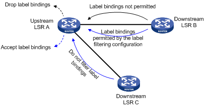
Label acceptance control
Label acceptance control is for filtering received label bindings. An upstream LSR filters the label bindings received from the specified downstream LSR and accepts only those permitted by the specified prefix list. As shown in Figure 8, upstream router LSR A filters the label bindings received from downstream router LSR B. Only if the destination address of an FEC matches the specified prefix list, does LSR A accept the label binding of the FEC from LSR B. LSR A does not filter label bindings received from downstream router LSR C.
Figure 8 Network diagram for label acceptance control
Label advertisement control
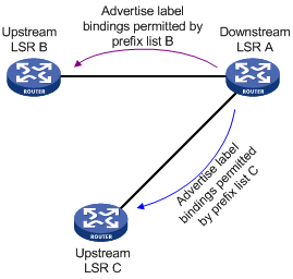
Label advertisement control is for filtering label bindings to be advertised. A downstream LSR advertises only the label bindings of the specified FECs to the specified upstream LSR. As shown in Figure 9, downstream router LSR A advertises to upstream router LSR B only label bindings with FEC destinations permitted by prefix list B, and advertises to upstream router LSR C only label bindings with FEC destinations permitted by prefix list C.
Figure 9 Network diagram for label advertisement control
Configuration prerequisites
Before you configure LDP label filtering policies, you must create an IP prefix list. For information about IP prefix list configuration, see Layer 3—IP Routing Configuration Guide.
Configuring LDP lable filtering
To configure LDP label filtering policies:
|
Step |
Command |
Remarks |
|
1. Enter system view. |
system-view |
N/A |
|
2. Enter MPLS LDP view. |
mpls ldp |
N/A |
|
3. Configure a label acceptance control policy. |
accept-label peer peer-id ip-prefix ip-prefix-name |
Optional. Not configured by default. |
|
4. Configure a label advertisement control policy. |
advertise-label ip-prefix ip-prefix-name [ peer peer-ip-prefix-name ] |
Not configured by default. |
|
|
NOTE: For two neighboring LSRs, configuring a label acceptance control policy on the upstream LSR and configuring a label advertisement control policy on the downstream LSR can achieve the same effect. To reduce the network load, H3C recommends configuring only label advertisement control policies. |
Maintaining LDP sessions
This section describes how to detect communication failures between remote LDP peers and reset LDP sessions.
Configuring BFD for MPLS LDP
MPLS itself cannot detect a neighbor failure or link failure in time. If communication between two remote LDP peers fails, the LDP session will be down, and as a result, MPLS forwarding will fail. By cooperating with bidirectional forwarding detection (BFD), MPLS LDP can be quickly aware of communication failures between remote LDP peers, improving performances of existing MPLS networks.
|
|
NOTE: · For more information about BFD, see High Availability Configuration Guide. · An LSP can be bound to only one BFD session. |
To configure BFD for MPLS LDP:
|
Step |
Command |
Remarks |
|
1. Enter system view. |
system-view |
N/A |
|
2. Enter MPLS LDP remote peer view. |
mpls ldp remote-peer remote-peer-name |
N/A |
|
3. Enable BFD for MPLS LDP. |
remote-ip bfd |
Disabled by default |
|
|
NOTE: The cooperation of MPLS LDP and BFD can be used to detect communication failures between remote LDP peers only. For related configuration examples, see the chapter “Configuring VPLS.” |
Resetting LDP sessions
If you change LDP session parameters when some LDP sessions are up, the LDP sessions will not be able to function normally. In this case, you need to reset the LDP session so that the LDP peers renegotiate parameters and establish new sessions.
Use the following command to reset LDP sessions:
|
Task |
Command |
Remarks |
|
Reset LDP sessions. |
reset mpls ldp [ all | [ vpn-instance vpn-instance-name ] [ fec mask | peer peer-id ] ] |
Available in user view |
Managing and optimizing MPLS forwarding
Configuring MPLS MTU
An MPLS label stack is inserted between the link layer header and network layer header of a packet. During MPLS forwarding, a packet, after encapsulated with an MPLS label, may exceed the allowed length of the link layer and thus cannot be forwarded, although the network layer packet is smaller than the MTU of the interface.
To address the issue, you can configure the MPLS MTU on an interface of an LSR. Then, the LSR will compare the length of an MPLS packet against the configured MPLS MTU on the interface. When the packet is larger than the MPLS MTU:
· If fragmentation is allowed, the LSR removes the label stack from the packet, fragments the IP packet (the length of a fragment is the MPLS MTU minus the length of the label stack), adds the label stack back into each fragment, and then forwards the fragments.
· If fragmentation is not allowed, the LSR drops the packet directly.
To configure the MPLS MTU of an interface:
|
Step |
Command |
Remarks |
|
1. Enter system view. |
system-view |
N/A |
|
2. Enter interface view. |
interface interface-type interface-number |
N/A |
|
3. Configure the MPLS MTU of the interface. |
mpls mtu value |
By default, the MPLS MTU of an interface is not configured. |
|
|
NOTE: · MPLS packets carrying L2VPN or IPv6 packets are always successfully forwarded, even if they are larger than the MPLS MTU. · If the MPLS MTU of an interface is greater than the MTU of the interface, data forwarding may fail on the interface. · If you do not configure the MPLS MTU of an interface, fragmentation of MPLS packets will be based on the MTU of the interface, and the length of fragments does not take the MPLS labels into account. Thus, the length of an MPLS fragment may be larger than the interface’s MTU. |
Configuring TTL processing mode at ingress
At the ingress of an LSP, a label stack encapsulated with a TTL field is added to each packet. Whether the label TTL takes the IP TTL or not depends on whether IP TTL propagation is enabled.
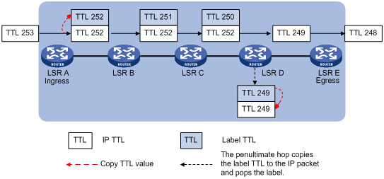
· With IP TTL propagation enabled: When the ingress labels a packet, it copies the TTL value of the original IP packet to the TTL field of the label. When an LSR forwards the labeled packet, it decrements the TTL value of the label at the stack top by 1. When an LSR pops a label, it copies the TTL value of the label at the stack top back to the TTL field of the IP packet. In this case, the TTL value of a packet is decreased hop by hop when forwarded along the LSP. Therefore, the result of tracert will reflect the real path along which the packet has traveled.
Figure 10 Label TTL processing when IP TTL propagation is enabled
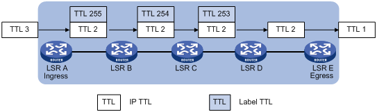
· With IP TTL propagation disabled: When the ingress labels a packet, it does not copy the TTL value of the original IP packet to the TTL field of the label, and the label TTL is set to 255. When an LSR forwards the labeled packet, it decrements the TTL value of the label at the stack top by 1. When an LSR pops a label, it compares the IP TTL and the label TTL and uses the smaller value as the TTL of the IP packet. In this case, the result of tracert does not show the hops within the MPLS backbone, as if the ingress and egress were connected directly.
Figure 11 Label TTL processing when IP TTL propagation is disabled
To configure IP TTL propagation of MPLS:
|
Step |
Command |
Remarks |
|
1. Enter system view. |
system-view |
N/A |
|
2. Enter MPLS view. |
mpls |
N/A |
|
Enable MPLS IP TTL propagation. |
ttl propagate { public | vpn } |
Optional. Enabled for only public network packets by default. |
|
|
CAUTION: · Within an MPLS domain, TTL is always copied between multiple levels of labels. The ttl propagate command affects only the propagation of the IP TTL to the TTL of an MPLS label. Therefore, this command takes effect only when it is configured on the ingress. · For locally generated packets, an LSR always copies the IP TTL value of the packet, regardless of whether IP TTL propagation is enabled or not. This ensures that the local administrator can tracert for network diagnoses. · If you enable MPLS IP TTL propagation for VPN packets on one LSR, H3C recommends that you enable it on all related provider edge (PE) devices, so you can get the same result when tracerting from those PEs. For more information about PE, see the chapter “Configuring MPLS L3VPN.” |
Sending back ICMP TTL exceeded messages for MPLS TTL expired packets
After you enable an LSR to send back ICMP TTL exceeded messages for MPLS TTL expired packets, when the LSR receives an MPLS packet that carries a label with TTL being 1, it will generate an ICMP TTL exceeded message, and send the message to the packet sender in one of the following ways:
· If the LSR has a route to the packet sender, it sends the ICMP TTL exceeded message to the packet sender directly through the IP route.
· If the LSR has no route to the packet sender, it forwards the ICMP TTL exceeded message along the LSP to the egress, which will send the message to the packet sender.
Usually, for an MPLS packet carrying only one level of label, the first method is used; for an MPLS packet carrying a multi-level label stack, the second method is used. However, because autonomous system boundary routers (ASBRs), superstratum PEs or service provider-end PEs (SPEs) in Hierarchy of VPN (HoVPN) applications, and carrier backbone PEs in nested VPNs may receive MPLS VPN packets that carry only one level of label but these devices have no IP routes to the packet senders, the first method is not applicable. In this case, you can configure the undo ttl expiration pop command on these devices so that the devices use the second method.
|
|
NOTE: For more information about HoVPN and nested VPN, see the chapter “Configuring MPLS L3VPN.” |
To configure the router to send back an ICMP TTL exceeded message for a received MPLS TTL expired packet:
|
Step |
Command |
Remarks |
|
1. Enter system view. |
system-view |
N/A |
|
2. Enter MPLS view. |
mpls |
N/A |
|
3. Enable the device to send back an ICMP TTL exceeded message when it receives an MPLS TTL expired packet. |
ttl expiration enable |
Optional. Enabled by default. |
|
4. Configure the router to use IP routes or LSPs to send back the ICMP TTL exceeded messages for TTL-expired MPLS packets that have only one level of label. |
· (Approach 1) Use IP routes: · (Approach 2) Use LSP routes: |
Optional. Use either approach as required. By default, an ICMP TTL exceeded message is sent back along an IP route when the TTL of an MPLS packet with a one-level label stack expires. This configuration does not take effect when the MPLS packets carry multiple levels of labels. ICMP TTL exceeded messages for such MPLS packets always travel along the LSPs. |
Configuring LDP GR
MPLS has two separate planes: the forwarding plane and the control plane. Using this feature, LDP Graceful Restart (GR) preserves the LFIB information when the signaling protocol or control plane fails, so that LSRs can still forward packets according to LFIB, ensuring continuous data transmission.
A router that participates in a GR process plays either of two roles:
· GR restarter, the router that gracefully restarts due to a manually configured command or a fault. It must be GR-capable.
· GR helper, neighbor of the GR restarter. A GR helper maintains the neighbor relationship with the GR restarter and helps the GR restarter restore its LFIB information. A GR helper must be GR-capable.
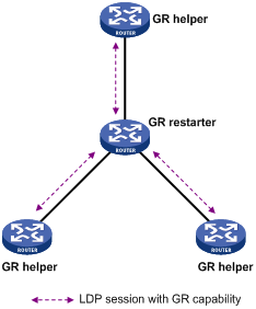
As shown in Figure 12, two LDP peers perform GR negotiation when establishing an LDP session. The LDP session established is GR capable only when both peers support LDP GR.
The working procedure of LDP GR is as follows:
1. Whenever restarting, the GR restarter preserves all MPLS forwarding entries, marks them as stale, and starts the MPLS forwarding state holding timer for them.
2. After a GR helper detects that the LDP session with the GR restarter is down, it marks the FEC-label bindings learned from the session as stale and will keep these FEC-label bindings for a period of time defined by the fault tolerant (FT) reconnect time argument. The FT reconnect time is the smaller one between the reconnect time advertised from the peer GR restarter and the neighbor liveness time configured locally.
3. During the FT reconnect time, if the LDP session fails to be re-established, the GR helper will delete the FEC-label bindings marked stale.
4. If the session is re-established successfully, during the LDP recovery time, the GR helper and the GR restarter will use the new LDP session to exchange the label mapping information, update the LFIB, and delete the stale marks of the corresponding forwarding entries. The LDP recovery time is the smaller one between the recovery time configured locally and that configured on the peer GR restarter.
5. After the recovery time elapses, the GR helper deletes the FEC-label bindings that are still marked stale.
6. When the MPLS forwarding state holding timer expires, the GR restarter deletes the label forwarding entries that are still marked stale.
Configuration prerequisites
Before you configure LDP GR, configure MPLS LDP capability on each router that will act as the GR restarter or a GR helper.
|
|
NOTE: The router can act as a GR restarter or a GR helper as needed in the LDP GR process. |
Configuring LDP GR
To configure LDP GR:
|
Step |
Command |
Remarks |
|
1. Enter system view. |
system-view |
N/A |
|
2. Enter MPLS LDP view. |
mpls ldp |
N/A |
|
3. Enable MPLS LDP GR. |
graceful-restart |
Disabled by default |
|
4. Set the FT reconnect time. |
graceful-restart timer reconnect timer |
Optional 300 seconds by default |
|
5. Set the LDP neighbor liveness time. |
graceful-restart timer neighbor-liveness timer |
Optional 120 seconds by default |
|
6. Set the LDP recovery time. |
graceful-restart timer recovery timer |
Optional 300 seconds by default |
Gracefully restarting MPLS LDP
To test whether the MPLS LDP GR configuration has taken effect, you can perform graceful restart of MPLS LDP. During the LDP restart process, you can see whether the packet forwarding path is changed and whether packet forwarding is interrupted.
To restart MPLS LDP gracefully:
|
Task |
Command |
Remarks |
|
Restart MPLS LDP gracefully. |
graceful-restart mpls ldp |
Available in user view |
|
|
NOTE: The graceful-restart mpls ldp command is only used to test MPLS LDP GR function. It does not perform active/standby switchover. Do not perform this operation in other cases. |
Configuring MPLS statistics
To view LSP statistics, you must set the interval for reading LSP statistics at first.
Setting the interval for reading statistics
To set the interval for reading LSP statistics:
|
Step |
Command |
Remarks |
|
1. Enter system view. |
system-view |
N/A |
|
2. Enter MPLS view. |
mpls |
N/A |
|
3. Set the interval for reading LSP statistics. |
statistics interval interval-time |
0 seconds by default, meaning that the system does not read LSP statistics. |
Inspecting LSPs
In MPLS, the MPLS control plane is responsible for establishing LSPs. However, when an LSP fails to forward data, the control plane cannot detect the LSP failure or cannot do so in time. This brings difficulty to network maintenance. To find LSP failures in time and locate the failed node, the router provides the following mechanisms:
· MPLS LSP ping
· MPLS LSP tracert
· BFD for LSPs
MPLS LSP ping
MPLS LSP ping is for checking the connectivity of an LSP. At the ingress, it adds the label for the FEC to be inspected into an MPLS echo request, which then is forwarded along the LSP to the egress. The egress processes the request packet and returns an MPLS echo reply to the ingress. An MPLS echo reply carrying a success notification indicates that the lSP is normal, and an MPLS echo reply carrying an error code indicates that the LSP has failed.
To check the connectivity of an LSP:
|
Task |
Command |
Remarks |
|
Use MPLS LSP ping to check the connectivity of an MPLS LSP. |
ping lsp [ -a source-ip | -c count | -exp exp-value | -h ttl-value | -m wait-time | -r reply-mode | -s packet-size | -t time-out | -v ] * ipv4 dest-addr mask-length [ destination-ip-addr-header ] |
Available in any view |
MPLS LSP tracert
MPLS LSP tracert is for locating LSP errors. It consecutively sends the MPLS echo requests along the LSP to be inspected, with the TTL increasing from 1 to a specific value. Then, each hop along the LSP will return an MPLS echo reply to the ingress due to TTL timeout. Thus, the ingress can collect the information of each hop along the LSP, so as to locate the failed node. You can also use MPLS LSP tracert to collect the important information of each hop along the LSP, such as the label allocated.
To locate errors of an LSP:
|
Task |
Command |
Remarks |
|
Perform MPLS LSP tracert to locate an MPLS LSP error. |
tracert lsp [ -a source-ip | -exp exp-value | -h ttl-value | -r reply-mode |-t time-out ] * ipv4 dest-addr mask-length [ destination-ip-addr-header ] |
Available in any view |
Configuring BFD for LSPs
You can configure BFD for an LSP to detect the connectivity of the LSP. After the configuration, a BFD session will be established between the ingress and egress of the LSP, and the ingress will add the label for the FEC to into a BFD control packet, forward the BFD control packet along the LSP to the egress, and determine the status of the LSP according to the reply received. Upon detecting an LSP failure, BFD triggers a traffic switchover.
A BFD session for LSP connectivity detection can be static or dynamic.
· Static: If you specify the local and remote discriminator values by using the discriminator keyword when configuring the bfd enable command, the BFD session will be established with the specified discriminator values. Such a BFD session is used to detect the connectivity of a pair of LSPs in opposite directions (one from local to remote, and the other from remote to local) between two routers.
· Dynamic: If you do not specify the local and remote discriminator values when configuring the bfd enable command, the MPLS LSP ping will be run automatically to negotiate the discriminator values and then the BFD session will be established based on the negotiated discriminator values. Such a BFD session is used for connectivity detection of an LSP from the local router to the remote router.
Configuration prerequistes
· The BFD session parameters are those configured on the loopback interface whose IP address is configured as the MPLS LSR ID, and the BFD packets will use the MPLS LSR ID as the source address. Therefore, before enabling BFD for an LSP, you need to configure an IP address for the loopback interface and configure the IP address as the MPLS LSR ID. You can also configure BFD session parameters for the loopback interface as needed. For more information about BFD, see High Availability Configuration Guide.
· To establish a static BFD session, make sure that there is already an LSP from the local router to the remote router and an LSP from the remote router to the local router.
Configuring BFD for LSPs
To configure BFD for LSPs:
|
Step |
Command |
Remarks |
|
1. Enter system view. |
system-view |
N/A |
|
2. Enable LSP verification and enter the MPLS LSPV view. |
mpls lspv |
Disabled by default |
|
3. Configure BFD to check the connectivity of the LSPs to the specified FEC destination. |
bfd enable destination-address mask-length [ nexthop nexthop-address [ discriminator local local-id remote remote-id ] ] |
Not configured by default |
|
|
NOTE: · You cannot establish both a static BFD session and a dynamic BFD session for the same LSP. · After a static BFD session is established, it is not allowed to modify the discriminator values of the BFD session. · In a BFD session for detecting LSP connectivity, the ingress node always works in active mode and the egress node always works in passive mode. The bfd session init-mode command does not take effect on the ingress and egress nodes of such a BFD session. Even if you configure the two nodes to both work in passive mode, the BFD session will still be established successfully. · BFD for MPLS LDP is for detecting the IP connectivity between two remote LDP peers. BFD for LSP is for detecting the connectivity of LSPs. |
Configuring periodic LSP tracert
The periodic LSP tracert function is for locating faults of an LSP periodically. It detects the consistency of the forwarding plane and control plane and records detection results into logs. You can know whether an LSP has failed by checking the logs.
If you configure BFD as well as periodic tracert for an LSP, once the periodic LSP tracert function detects an LSP fault or inconsistency of the forwarding plane and control plane, the BFD session for the LSP will be deleted and a new BFD session will be established according to the control plane.
To configure the periodic LSP tracert function:
|
Step |
Command |
Remarks |
|
1. Enter system view. |
system-view |
N/A |
|
2. Enable LSP verification and enter the MPLS LSPV view. |
mpls lspv |
Disabled by default |
|
3. Configure periodic tracert for an LSP to the specified FEC destination. |
periodic-tracert destination-address mask-length [ -a source-ip | -exp exp-value | -h ttl-value | -m wait-time | -t time-out | -u retry-attempt ] * |
Not configured by default |
Enabling MPLS trap
If the MPLS trap function is enabled, trap packets of the notifications level will be generated to report critical MPLS events. Such trap packets will be sent to the information center of the router. Whether and where the packets will then be output depend on the configurations of the information center. For more information about the information center, see Network Management and Monitoring Configuration Guide.
To enable the MPLS trap function:
|
Step |
Command |
Remarks |
|
1. Enter system view. |
system-view |
N/A |
|
2. Enable the MPLS trap function. |
snmp-agent trap enable mpls |
Disabled by default |
|
|
NOTE: For more information about the snmp-agent trap enable mpls command, see Network Management and Monitoring Command Reference. |
Displaying and maintaining MPLS
Displaying MPLS operation
|
Task |
Command |
Remarks |
|
Display information about a specific or all interfaces with MPLS enabled. |
display mpls interface [ interface-type interface-number ] [ verbose ] [ | { begin | exclude | include } regular-expression ] |
Available in any view |
|
Display information about the ILM table. |
display mpls ilm [ label ] [ verbose ] [ slot slot-number ] [ include text | { | { begin | exclude | include } regular-expression } ] |
Available in any view |
|
Display the usage information of the specified or all labels. |
display mpls label { label-value1 [ to label-value2 ] | all } [ | { begin | exclude | include } regular-expression ] |
Available in any view |
|
Display information about LSPs. |
display mpls lsp [ incoming-interface interface-type interface-number ] [ outgoing-interface interface-type interface-number ] [ in-label in-label-value ] [ out-label out-label-value ] [ asbr | [ vpn-instance vpn-instance-name ] [ protocol { bgp | bgp-ipv6 | crldp | ldp | rsvp-te | static | static-cr } ] ] [ egress | ingress | transit ] [ { exclude | include } dest-addr mask-length ] [ verbose ] [ | { begin | exclude | include } regular-expression ] |
Available in any view |
|
Display LSP statistics. |
display mpls lsp statistics [ | { begin | exclude | include } regular-expression ] |
Available in any view |
|
Display the BFD detection information for an LSP. |
display mpls lsp bfd [ ipv4 destination-address mask-length ] [ | { begin | exclude | include } regular-expression ] |
Available in any view |
|
Display information about the NHLFE table. |
display mpls nhlfe [ token ] [ verbose ] [ slot slot-number ] [ include text | { | { begin | exclude | include } regular-expression } ] |
Available in any view |
|
Display usage information about the NHLFE entries. |
display mpls nhlfe reflist token [ slot slot-number ] [ include text | { | { begin | exclude | include } regular-expression } ] |
Available in any view |
|
Display information about static LSPs. |
display mpls static-lsp [ lsp-name lsp-name ] [ { include | exclude } dest-addr mask-length ] [ verbose ] [ | { begin | exclude | include } regular-expression ] |
Available in any view |
|
Display information about LSPs over specified or all routes for the public or a specific private network. |
display mpls route-state [ vpn-instance vpn-instance-name ] [ dest-addr mask-length ] [ | { begin | exclude | include } regular-expression ] |
Available in any view |
|
Display MPLS statistics for a specific or all LSPs. |
display mpls statistics lsp { index | all | name lsp-name } [ | { begin | exclude | include } regular-expression ] |
Available in any view |
|
Display MPLS statistics for a specific or all interfaces. |
display mpls statistics interface { interface-type interface-number | all } [ | { begin | exclude | include } regular-expression ] |
Available in any view |
Displaying MPLS LDP operation
|
Task |
Command |
Remarks |
|
Display information about LDP. |
display mpls ldp [ all [ verbose ] [ | { begin | exclude | include } regular-expression ] ] |
Available in any view |
|
Display the label advertisement information of the specified FEC. |
display mpls ldp fec [ vpn-instance vpn-instance-name ] dest-addr mask-length [ | { begin | exclude | include } regular-expression ] |
Available in any view |
|
Display information about LDP-enabled interfaces. |
display mpls ldp interface [ all [ verbose ] | [ vpn-instance vpn-instance-name ] [ interface-type interface-number | verbose ] ] [ | { begin | exclude | include } regular-expression ] |
Available in any view |
|
Display information about LDP peers. |
display mpls ldp peer [ all [ verbose ] | [ vpn-instance vpn-instance-name ] [ peer-id | verbose ] ] [ | { begin | exclude | include } regular-expression ] |
Available in any view |
|
Display information about remote LDP peers. |
display mpls ldp remote-peer [ remote-name remote-peer-name ] [ | { begin | exclude | include } regular-expression ] |
Available in any view |
|
Display information about LDP sessions between LDP peers. |
display mpls ldp session [ all [ verbose] | [ vpn-instance vpn-instance-name ] [ peer-id | verbose ] ] [ | { begin | exclude | include } regular-expression ] |
Available in any view |
|
Display statistics information about all LSP sessions. |
display mpls ldp session all statistics [ | { begin | exclude | include } regular-expression ] |
Available in any view |
|
Display information about LSPs established by LDP. |
display mpls ldp lsp [ all | [ vpn-instance vpn-instance-name ] [ dest-addr mask-length ] ] [ | { begin | exclude | include } regular-expression ] |
Available in any view |
|
Display information about CR-LSPs established by CR-LDP. |
display mpls ldp cr-lsp [ lspid lsr-id lsp-id ] [ | { begin | exclude | include } regular-expression ] |
Available in any view |
|
|
NOTE: In these display commands, vpn-instance vpn-instance-name specifies an LDP instance. For information about LDP instances, see the chapter “Configuring MPLS L3VPN.” |
Clearing MPLS statistics
|
Task |
Command |
Remarks |
|
Clear MPLS statistics for a specific MPLS interface or all MPLS interfaces. |
reset mpls statistics interface { interface-type interface-number | all } |
Available in user view |
|
Clear MPLS statistics for a specific LSP or all LSPs. |
reset mpls statistics lsp { index | all | name lsp-name } |
Available in user view |
MPLS configuration examples
Configuring static LSPs
Network requirements
Router A, Router B, and Router C support MPLS.
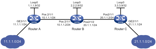
Establish static LSPs between Router A and Router C so that subnets 10.1.1.0/24 and 21.1.1.0/24 can access each other over MPLS. Check the connectivity of the static LSPs.
Configuration considerations
· On an LSP, the outgoing label of an upstream LSR must be identical with the incoming label of its downstream LSR.
· Configure an LSP for each direction on the forwarding path.
· Configure a static route to the destination address of the LSP on each ingress node. There is no need to configure such a static route on the transit and egress nodes and thus you do not need to configure any routing protocol on the routers.
Configuration procedure
1. Configure the IP addresses of the interfaces.
Configure the IP addresses and masks of the interfaces including the loopback interfaces as required in Figure 13. (Details not shown)
2. Configure a static route to the destination address of the FEC on each ingress node.
# Configure a static route to network 21.1.1.0/24 on Router A.
<RouterA> system-view
[RouterA] ip route-static 21.1.1.0 24 10.1.1.2
# Configure a static route to network 11.1.1.0/24 on Router C.
<RouterC> system-view
[RouterC] ip route-static 11.1.1.0 255.255.255.0 20.1.1.1
3. Enable MPLS.
# Configure MPLS on Router A.
[RouterA] mpls lsr-id 1.1.1.9
[RouterA] mpls
[RouterA-mpls] quit
[RouterA] interface Pos 2/1/1
[RouterA-Pos2/1/1] mpls
[RouterA-Pos2/1/1] quit
# Configure MPLS on Router B.
[RouterB] mpls lsr-id 2.2.2.9
[RouterB] mpls
[RouterB-mpls] quit
[RouterB] interface Pos 2/1/1
[RouterB-Pos2/1/1] mpls
[RouterB-Pos2/1/1] quit
[RouterB] interface Pos 2/1/2
[RouterB-Pos2/1/2] mpls
[RouterB-Pos2/1/2] quit
# Configure MPLS on Router C.
[RouterC] mpls lsr-id 3.3.3.9
[RouterC] mpls
[RouterC-mpls] quit
[RouterC] interface Pos 2/1/1
[RouterC-Pos2/1/1] mpls
[RouterC-Pos2/1/1] quit
4. Configure a static LSP from Router A to Router C.
# Configure the LSP ingress, Router A.
[RouterA] static-lsp ingress AtoC destination 21.1.1.0 24 nexthop 10.1.1.2 out-label 30
# Configure the LSP transit node, Router B.
[RouterB] static-lsp transit AtoC incoming-interface Pos 2/1/1 in-label 30 nexthop 20.1.1.2 out-label 50
# Configure the LSP egress, Router C.
[RouterC] static-lsp egress AtoC incoming-interface Pos 2/1/1 in-label 50
5. Create a static LSP from Router C to Router A.
# Configure the LSP ingress, Router C.
[RouterC] static-lsp ingress CtoA destination 11.1.1.0 24 nexthop 20.1.1.1 out-label 40
# Configure the LSP transit node, Router B.
[RouterB] static-lsp transit CtoA incoming-interface Pos 2/1/2 in-label 40 nexthop 10.1.1.1 out-label 70
# Configure the LSP egress, Router A.
[RouterA] static-lsp egress CtoA incoming-interface Pos 2/1/1 in-label 70
6. Verify the configuration.
# Execute the display mpls static-lsp command on each router to view the static LSP information. The following takes Router A as an example:
[RouterA] display mpls static-lsp
total statics-lsp : 2
Name FEC I/O Label I/O If State
AtoC 21.1.1.0/24 NULL/30 -/Pos2/1/1 Up
CtoA -/- 70/NULL Pos2/1/1/- Up
# On Router A, check the reachability of the LSP from Router A to Router C.
[RouterA] ping lsp -a 11.1.1.1 ipv4 21.1.1.0 24
LSP Ping FEC: IPV4 PREFIX 21.1.1.0/24 : 100 data bytes, press CTRL_C to break
Reply from 20.1.1.2: bytes=100 Sequence=1 time = 2 ms
Reply from 20.1.1.2: bytes=100 Sequence=2 time = 2 ms
Reply from 20.1.1.2: bytes=100 Sequence=3 time = 1 ms
Reply from 20.1.1.2: bytes=100 Sequence=4 time = 2 ms
Reply from 20.1.1.2: bytes=100 Sequence=5 time = 2 ms
--- FEC: IPV4 PREFIX 21.1.1.0/24 ping statistics ---
5 packet(s) transmitted
5 packet(s) received
0.00% packet loss
round-trip min/avg/max = 1/1/2 ms
# On Router C, check the reachability of the LSP from Router C to Router A.
[RouterC] ping lsp -a 21.1.1.1 ipv4 11.1.1.0 24
LSP Ping FEC: IPV4 PREFIX 11.1.1.0/24 : 100 data bytes, press CTRL_C to break
Reply from 10.1.1.1: bytes=100 Sequence=1 time = 3 ms
Reply from 10.1.1.1: bytes=100 Sequence=2 time = 2 ms
Reply from 10.1.1.1: bytes=100 Sequence=3 time = 2 ms
Reply from 10.1.1.1: bytes=100 Sequence=4 time = 2 ms
Reply from 10.1.1.1: bytes=100 Sequence=5 time = 2 ms
--- FEC: IPV4 PREFIX 11.1.1.0/24 ping statistics ---
5 packet(s) transmitted
5 packet(s) received
0.00% packet loss
round-trip min/avg/max = 2/2/3 ms
Configuring LDP to establish LSPs dynamically
Network requirements
Router A, Router B, and Router C support MPLS.
Configure LDP to establish LSPs between Router A and Router C so that subnets 11.1.1.0/24 and 21.1.1.0/24 can reach each other over MPLS. Check the LSP connectivity.
Configuration considerations
· Enable LDP on the LSRs. LDP dynamically distributes labels and establishes LSPs and thus there is no need to manually configure labels for LSPs.
· LDP uses routing information for label distribution. Therefore, you need to configure a routing protocol to learn routing information. OSPF is used in this example.
Configuration procedure
1. Configure the IP addresses of the interfaces.
Configure the IP addresses and masks of the interfaces including the loopback interfaces as required in Figure 14. (Details not shown)
2. Configure OSPF to ensure IP connectivity between the routers.
# Configure OSPF on Router A.
<RouterA> system-view
[RouterA] ospf
[RouterA-ospf-1] area 0
[RouterA-ospf-1-area-0.0.0.0] network 1.1.1.9 0.0.0.0
[RouterA-ospf-1-area-0.0.0.0] network 10.1.1.0 0.0.0.255
[RouterA-ospf-1-area-0.0.0.0] network 11.1.1.0 0.0.0.255
[RouterA-ospf-1-area-0.0.0.0] quit
[RouterA-ospf-1] quit
# Configure OSPF on Router B.
<RouterB> system-view
[RouterB] ospf
[RouterB-ospf-1] area 0
[RouterB-ospf-1-area-0.0.0.0] network 2.2.2.9 0.0.0.0
[RouterB-ospf-1-area-0.0.0.0] network 10.1.1.0 0.0.0.255
[RouterB-ospf-1-area-0.0.0.0] network 20.1.1.0 0.0.0.255
[RouterB-ospf-1-area-0.0.0.0] quit
[RouterB-ospf-1] quit
# Configure OSPF on Router C.
<RouterC> system-view
[RouterC] ospf
[RouterC-ospf-1] area 0
[RouterC-ospf-1-area-0.0.0.0] network 3.3.3.9 0.0.0.0
[RouterC-ospf-1-area-0.0.0.0] network 20.1.1.0 0.0.0.255
[RouterC-ospf-1-area-0.0.0.0] network 21.1.1.0 0.0.0.255
[RouterC-ospf-1-area-0.0.0.0] quit
[RouterC-ospf-1] quit
# Execute the display ip routing-table command on each router. You will see that each router has learned the routes to other routers. Take Router A as an example:
[RouterA] display ip routing-table
Routing Tables: Public
Destinations : 11 Routes : 11
Destination/Mask Proto Pre Cost NextHop Interface
1.1.1.9/32 Direct 0 0 127.0.0.1 InLoop0
2.2.2.9/32 OSPF 10 1 10.1.1.2 Pos2/1/1
3.3.3.9/32 OSPF 10 2 10.1.1.2 Pos2/1/1
10.1.1.0/24 Direct 0 0 10.1.1.1 Pos2/1/1
10.1.1.1/32 Direct 0 0 127.0.0.1 InLoop0
11.1.1.0/24 Direct 0 0 11.1.1.1 GE3/1/1
11.1.1.1/32 Direct 0 0 127.0.0.1 InLoop0
20.1.1.0/24 OSPF 10 2 10.1.1.2 Pos2/1/1
21.1.1.0/24 OSPF 10 3 10.1.1.2 Pos2/1/1
127.0.0.0/8 Direct 0 0 127.0.0.1 InLoop0
127.0.0.1/32 Direct 0 0 127.0.0.1 InLoop0
3. Enable MPLS and MPLS LDP.
# Configure MPLS and MPLS LDP on Router A.
[RouterA] mpls lsr-id 1.1.1.9
[RouterA] mpls
[RouterA-mpls] quit
[RouterA] mpls ldp
[RouterA-mpls-ldp] quit
[RouterA] interface Pos 2/1/1
[RouterA-Pos2/1/1] mpls
[RouterA-Pos2/1/1] mpls ldp
[RouterA-Pos2/1/1] quit
# Configure MPLS and MPLS LDP on Router B.
[RouterB] mpls lsr-id 2.2.2.9
[RouterB] mpls
[RouterB-mpls] quit
[RouterB] mpls ldp
[RouterB-mpls-ldp] quit
[RouterB] interface Pos 2/1/1
[RouterB-Pos2/1/1] mpls
[RouterB-Pos2/1/1] mpls ldp
[RouterB-Pos2/1/1] quit
[RouterB] interface Pos 2/1/2
[RouterB-Pos2/1/2] mpls
[RouterB-Pos2/1/2] mpls ldp
[RouterB-Pos2/1/2] quit
# Configure MPLS and MPLS LDP on Router C.
[RouterC] mpls lsr-id 3.3.3.9
[RouterC] mpls
[RouterC-mpls] quit
[RouterC] mpls ldp
[RouterC-mpls-ldp] quit
[RouterC] interface Pos 2/1/1
[RouterC-Pos2/1/1] mpls
[RouterC-Pos2/1/1] mpls ldp
[RouterC-Pos2/1/1] quit
# After the configurations, two local LDP sessions are established, one between Router A and Router B and the other between Router B and Router C. Execute the display mpls ldp session command on each router to view the LDP session information, and execute the display mpls ldp peer command to view the LDP peer information. Take Router A as an example:
[RouterA] display mpls ldp session
LDP Session(s) in Public Network
Total number of sessions: 1
----------------------------------------------------------------
Peer-ID Status LAM SsnRole FT MD5 KA-Sent/Rcv
----------------------------------------------------------------
2.2.2.9:0 Operational DU Passive Off Off 5/5
----------------------------------------------------------------
LAM : Label Advertisement Mode FT : Fault Tolerance
[RouterA] display mpls ldp peer
LDP Peer Information in Public network
Total number of peers: 1
-----------------------------------------------------------------
Peer-ID Transport-Address Discovery-Source
----------------------------------------------------------------
2.2.2.9:0 2.2.2.9 Pos2/1/1
----------------------------------------------------------------
4. Allow all static routes and IGP routes to trigger establishment of LSPs.
# Configure the LSP establishment triggering policy on Router A.
[RouterA] mpls
[RouterA-mpls] lsp-trigger all
[RouterA-mpls] quit
# Configure the LSP establishment triggering policy on Router B.
[RouterB] mpls
[RouterB-mpls] lsp-trigger all
[RouterB-mpls] quit
# Configure the LSP establishment triggering policy on Router C.
[RouterC] mpls
[RouterC-mpls] lsp-trigger all
[RouterC-mpls] quit
5. Verify the configuration.
# Execute the display mpls ldp lsp command on each router to view the LDP LSP information. Take Router A as an example:
[RouterA] display mpls ldp lsp
LDP LSP Information
-------------------------------------------------------------------
SN DestAddress/Mask In/OutLabel Next-Hop In/Out-Interface
------------------------------------------------------------------
1 1.1.1.9/32 3/NULL 127.0.0.1 -------/InLoop0
2 2.2.2.9/32 NULL/3 10.1.1.2 -------/Pos2/1/1
3 3.3.3.9/32 NULL/1024 10.1.1.2 -------/Pos2/1/1
4 11.1.1.0/24 3/NULL 0.0.0.0 -------/GE3/1/1
5 20.1.1.0/24 NULL/3 10.1.1.2 -------/Pos2/1/1
6 21.1.1.0/24 NULL/1027 10.1.1.2 -------/Pos2/1/1
-------------------------------------------------------------------
A '*' before an LSP means the LSP is not established
A '*' before a Label means the USCB or DSCB is stale
# On Router A, check the connectivity of the LDP LSP from Router A to 21.1.1.0/24.
[RouterA] ping lsp ipv4 21.1.1.0 24
LSP Ping FEC: IPV4 PREFIX 21.1.1.0/24 : 100 data bytes, press CTRL_C to break
Reply from 20.1.1.2: bytes=100 Sequence=1 time = 3 ms
Reply from 20.1.1.2: bytes=100 Sequence=2 time = 2 ms
Reply from 20.1.1.2: bytes=100 Sequence=3 time = 1 ms
Reply from 20.1.1.2: bytes=100 Sequence=4 time = 1 ms
Reply from 20.1.1.2: bytes=100 Sequence=5 time = 3 ms
--- FEC: IPV4 PREFIX 21.1.1.0/24 ping statistics ---
5 packet(s) transmitted
5 packet(s) received
0.00% packet loss
round-trip min/avg/max = 1/2/3 ms
# On Router C, check the connectivity of the LDP LSP from Router C to 11.1.1.0/24.
[RouterC] ping lsp ipv4 11.1.1.0 24
LSP Ping FEC: IPV4 PREFIX 11.1.1.0/24 : 100 data bytes, press CTRL_C to break
Reply from 10.1.1.1: bytes=100 Sequence=1 time = 2 ms
Reply from 10.1.1.1: bytes=100 Sequence=2 time = 2 ms
Reply from 10.1.1.1: bytes=100 Sequence=3 time = 2 ms
Reply from 10.1.1.1: bytes=100 Sequence=4 time = 3 ms
Reply from 10.1.1.1: bytes=100 Sequence=5 time = 2 ms
--- FEC: IPV4 PREFIX 11.1.1.0/24 ping statistics ---
5 packet(s) transmitted
5 packet(s) received
0.00% packet loss
round-trip min/avg/max = 2/2/3 ms
Configuring BFD for LSP validity check
Network requirements
For the network diagram, see Figure 13. Make sure that two LDP LSPs are established between Router A and Router C. Use BFD to detect the connectivity of the LSPs.
Configuration procedure
1. Configure LDP sessions. For more information, see “Configuring LDP to establish LSPs dynamically.”
2. Enable BFD for LSP validity check.
# Configure Router A.
<RouterA> system-view
[RouterA] mpls lspv
[RouterA -mpls-lspv] bfd enable 21.1.1.0 24
[RouterA -mpls-lspv] quit
# Configure Router C.
<RouterC> system-view
[RouterC] mpls lspv
[RouterC-mpls-lspv] bfd enable 11.1.1.0 24
[RouterC-mpls-lspv] quit
3. Verify the configuration.
Execute the display mpls lsp bfd command on Router A and Router C to view information about BFD sessions established for LSPs. Take Router A as an example:
[RouterA] display mpls lsp bfd
MPLS BFD Session(s) Information
-----------------------------------------------------------------------------
FEC : 11.1.1.0/24 Type : LSP
Local Discr : 130 Remote Discr : 130
Tunnel ID : --- NextHop : ---
Session State : Up Source IP : 3.3.3.9
Session Role : Passive
FEC : 21.1.1.0/24 Type : LSP
Local Discr : 129 Remote Discr : 129
Tunnel ID : 0x6040000 NextHop : 10.1.1.2
Session State : Up Source IP : 1.1.1.9
Session Role : Active
Total Session Num: 2
The output indicates that two BFD sessions have been established between 11.1.1.0/24 and 21.1.1.0/24: one for detecting the connectivity of the LSP from 1.1.1.0/24 to 21.1.1.0/24, and the other for detecting the connectivity of the LSP from 21.1.1.0/24 to 1.1.1.0/24.
Use the following command to view the verbose information of the BFD sessions:
[RouterA] display bfd session verbose
Total session number: 2 Up session number: 2 Init mode: Active
IPv4 session working under Ctrl mode:
Local Discr: 129 Remote Discr: 129
Source IP: 1.1.1.9 Destination IP: 127.0.0.1
Session State: Up Interface: LoopBack0
Min Trans Inter: 400ms Act Trans Inter: 400ms
Min Recv Inter: 400ms Act Detect Inter: 2000ms
Recv Pkt Num: 18 Send Pkt Num: 18
Hold Time: 1900ms Connect Type: Indirect
Running Up for: 00:02:36 Auth mode: None
Protocol: MFW/LSPV
Diag Info: No Diagnostic
Local Discr: 130 Remote Discr: 130
Source IP: 1.1.1.9 Destination IP: 3.3.3.9
Session State: Up Interface: LoopBack0
Min Trans Inter: 400ms Act Trans Inter: 400ms
Min Recv Inter: 400ms Act Detect Inter: 2000ms
Recv Pkt Num: 18 Send Pkt Num: 18
Hold Time: 1900ms Connect Type: Indirect
Running Up for: 00:02:28 Auth mode: None
Protocol: MFW/LSPV
Diag Info: No Diagnostic