- Table of Contents
-
- 03-Layer 2 - LAN Switching Configuration Guide
- 00-Preface
- 01-VLAN Configuration
- 02-MAC Address Table Configuration
- 03-Spanning Tree Configuration
- 04-Ethernet Link Aggregation Configuration
- 05-Port Isolation Configuration
- 06-QinQ Configuration
- 07-BPDU Tunneling Configuration
- 08-GVRP Configuration
- 09-VLAN Termination Configuration
- 10-LLDP Configuration
- Related Documents
-
| Title | Size | Download |
|---|---|---|
| 10-LLDP Configuration | 209.96 KB |
Contents
Performing basic LLDP configuration
Setting the LLDP re-initialization delay
Configuring the advertisable TLVs
Configuring the management address and its encoding format
Configuring the encapsulation format for LLDPDUs
Displaying and maintaining LLDP
Basic LLDP configuration example
CDP-compatible LLDP configuration example
Overview
Background
In a heterogeneous network, it is important that different types of devices from different vendors can discover one other and exchange configuration for interoperability and management sake. This calls for a standard configuration exchange platform.
To address this need, the IETF drafted the Link Layer Discovery Protocol (LLDP) in IEEE 802.1AB. The protocol operates on the data link layer to exchange device information between directly connected devices. With LLDP, a network device sends local device information (including its major functions, management IP address, device ID, and port ID) as TLV (type, length, and value) triplets in LLDPDUs to the directly connected network devices, and at the same time, stores the device information received in LLDPDUs sent from the LLDP neighbors in a standard management information base (MIB). This allows a network management system to quickly detect and identify the Layer-2 network topology change.
|
|
NOTE: For more information about MIBs, see Network Management and Monitoring Configuration Guide. |
Basic concepts
LLDP frames
LLDP sends device information in LLDP data units (LLDPDUs). LLDPDUs are encapsulated in Ethernet II or SNAP frames.
1. Ethernet II-encapsulated LLDP frame format
Figure 1 Ethernet II-encapsulated LLDP frame format
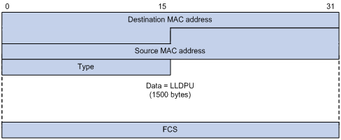
Table 1 Fields in an Ethernet II-encapsulated LLDP frame
|
Field |
Description |
|
Destination MAC address |
The MAC address to which the LLDPDU is advertised. It is fixed to 0x0180-C200-000E, a multicast MAC address. |
|
Source MAC address |
The MAC address of the sending port. If the port does not have a MAC address, the MAC address of the sending bridge is used. |
|
Type |
The Ethernet type for the upper layer protocol. It is 0x88CC for LLDP. |
|
Data |
LLDP data unit (LLDPDU). |
|
FCS |
Frame check sequence, a 32-bit CRC value used to determine the validity of the received Ethernet frame. |
2. SNAP-encapsulated LLDP frame format
Figure 2 SNAP-encapsulated LLDP frame format
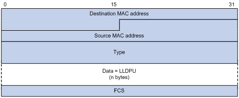
Table 2 Fields in a SNAP-encapsulated LLDP frame
|
Field |
Description |
|
Destination MAC address |
The MAC address to which the LLDPDU is advertised. It is fixed to 0x0180-C200-000E, a multicast MAC address. |
|
Source MAC address |
The MAC address of the sending port. If the port does not have a MAC address, the MAC address of the sending bridge is used. |
|
Type |
The SNAP type for the upper layer protocol. It is 0xAAAA-0300-0000-88CC for LLDP. |
|
Data |
LLDPDU. |
|
FCS |
Frame check sequence, a 32-bit CRC value used to determine the validity of the received Ethernet frame. |
LLDPDUs
LLDP uses LLDPDUs to exchange information. An LLDPDU comprises multiple TLV sequences, each carrying a type of device information, as shown in Figure 3.
Figure 3 Mandatory and optional TLVs in an LLDPDU
![]()
An LLDPDU can carry up to 28 types of TLVs. The chassis ID TLV, port ID TLV, TTL TLV, and end of LLDPDU TLV (end TLV in the figure) are mandatory TLVs that must be carried. Other TLVs are optional.
TLVs
TLVs are type, length, and value sequences that carry information elements, where the type field identifies the type of information, the length field indicates the length of the information field in octets, and the value field contains the information itself.
LLDPDU TLVs fall into the following categories:
· Basic management TLVs
· Organizationally (IEEE 802.1 and IEEE 802.3) specific TLVs
· LLDP-MED (media endpoint discovery) TLVs
Basic management TLVs are essential to device management. Organizationally specific TLVs and LLDP-MED TLVs are used for enhanced device management, and are defined by standardization or other organizations and thus are optional to LLDPDUs.
1. Basic management TLVs
Table 1 lists the basic management TLV types. Some of them are mandatory to LLDPDUs, and must be included in every LLDPDU.
Table 3 Basic LLDP TLVs
|
Type |
Description |
Remarks |
|
Chassis ID |
Bridge MAC address of the sending device |
Mandatory |
|
Port ID |
ID of the sending port. If MED TLVs are included in the LLDPDU, the port ID TLV carries the MAC address of the sending port or the bridge MAC in case the port does not have a MAC address. If no MED TLVs are included, the port ID TLV carries the port name. |
|
|
Time To Live |
Life of the transmitted information on the receiving device |
|
|
End of LLDPDU |
Marks the end of the TLV sequence in the LLDPDU |
|
|
Port Description |
Port description of the sending port |
Optional |
|
System Name |
Name of the sending device |
|
|
System Description |
Description of the sending device |
|
|
System Capabilities |
Identifies the primary functions of the sending device and the primary functions that have been enabled |
|
|
Management Address |
Management address used to reach higher level entities to assist discovery by network management, and the interface number and object identifier (OID) associated with the address |
2. IEEE 802.1 organizationally specific TLVs
Table 4 IEEE 802.1 organizationally specific TLVs
|
Type |
Description |
|
Port VLAN ID |
PVID of the sending port |
|
Port And Protocol VLAN ID |
Port and protocol VLAN IDs |
|
VLAN Name |
A specific VLAN name on the port |
|
Protocol Identity |
Protocols supported on the port |
|
|
NOTE: H3C routers support receiving but not sending protocol identity TLVs. |
3. IEEE 802.3 organizationally specific TLVs
Table 5 IEEE 802.3 organizationally specific TLVs
|
Type |
Description |
|
MAC/PHY Configuration/Status |
Contains the rate and duplex capabilities of the sending port, support for auto negotiation, enabling status of auto negotiation, and the current rate and duplex mode. |
|
Power Via MDI |
Contains Power supply capability of the port. |
|
Link Aggregation |
Indicates the support of the port for link aggregation, the aggregation capability of the port, and the aggregation status (that is, whether the link is in an aggregation). |
|
Maximum Frame Size |
Indicates the supported maximum frame size. It is now the MTU of the port. |
4. LLDP-MED TLVs
LLDP-MED TLVs provide multiple advanced applications for voice over IP (VoIP), such as basic configuration, network policy configuration, and address and directory management. LLDP-MED TLVs satisfy the voice device vendors’ requirements for cost effectiveness, ease of deployment, and ease of management. In addition, LLDP-MED TLVs make deploying voice devices in Ethernet easier. LLDP-MED TLVs are shown in Table 6.
|
Type |
Description |
|
LLDP-MED Capabilities |
Allows a network device to advertise the LLDP-MED TLVs it supports. |
|
Network Policy |
Allows a network device or terminal device to advertise VLAN ID of the specific port, VLAN type, and the Layer 2 and Layer 3 priorities for specific applications. |
|
Extended Power-via-MDI |
Allows a network device or terminal device to advertise power supply capability. This TLV is an extension of the Power Via MDI TLV. |
|
Hardware Revision |
Allows a terminal device to advertise its hardware version. |
|
Firmware Revision |
Allows a terminal device to advertise its firmware version. |
|
Software Revision |
Allows a terminal device to advertise its software version. |
|
Serial Number |
Allows a terminal device to advertise its serial number. |
|
Manufacturer Name |
Allows a terminal device to advertise its vendor name. |
|
Model Name |
Allows a terminal device to advertise its model name. |
|
Asset ID |
Allows a terminal device to advertise its asset ID. The typical case is that the user specifies the asset ID for the endpoint to facilitate directory management and asset tracking. |
|
Location Identification |
Allows a network device to advertise the appropriate location identifier information for a terminal device to use in the context of location-based applications. |
Management address
The management address of a network device is used by the network management system to identify and manage the device for topology maintenance and network management. The management address is encapsulated in the management address TLV.
How LLDP works
Operating Modes of LLDP
LLDP can operate in one of the following modes:
· TxRx mode—A port in this mode sends and receives LLDP frames.
· Tx mode—A port in this mode only sends LLDP frames.
· Rx mode—A port in this mode only receives LLDP frames.
· Disable mode—A port in this mode does not send or receive LLDP frames.
Each time the LLDP operating mode of a port changes, its LLDP protocol state machine re-initializes. An initialization delay, which is user configurable, prevents LLDP from being initialized too frequently at times of frequent operating mode change. With this delay configured, before a port can initialize LLDP, it must wait for the specified interval after the LLDP operating mode changes.
Transmitting LLDP frames
An LLDP-enabled port operating in TxRx mode or Tx mode sends LLDP frames to its directly connected network devices both periodically and when the local configuration changes. A frame transmit interval between two successive LLDP frames prevents the network from being overwhelmed by LLDP frames at times of frequent local device information change.
This interval is shortened to 1 second in either of the following cases:
· A new LLDP frame is received carrying device information new to the local device.
· The LLDP operating mode of the port changes from Disable/Rx to TxRx or Tx.
This is the fast sending mechanism of LLDP. With this mechanism, a specific number of LLDP frames are sent successively at the 1-second interval to help LLDP neighbors discover the local device as soon as possible. Then, the normal LLDP frame transmit interval resumes.
Receiving LLDP frames
An LLDP-enabled port operating in TxRx mode or Rx mode checks the TLVs carried in every LLDP frame it receives for validity violation. If valid, the information is saved and an aging timer is set for it based on the time to live (TTL) TLV carried in the LLDPDU. If the TTL TLV is zero, the information is aged out immediately.
Protocols and standards
The protocols and standards related to LLDP include:
· IEEE 802.1AB-2005, Station and Media Access Control Connectivity Discovery
· ANSI/TIA-1057, Link Layer Discovery Protocol for Media Endpoint Devices
LLDP configuration task list
Complete these tasks to configure LLDP:
|
Task |
Remarks |
|
|
Required |
||
|
Optional |
||
|
Optional |
||
|
Optional |
||
|
Optional |
||
|
Optional |
||
|
Optional |
||
|
Optional |
||
|
Optional |
||
|
Optional |
||
|
|
NOTE: LLDP-related configurations made in Ethernet interface view takes effect only on the current port, and those made in port group view takes effect on all ports in the current port group. |
Performing basic LLDP configuration
Enabling LLDP
To make LLDP take effect on specific ports, you must enable LLDP both globally and on these ports.
To enable LLDP on the router:
|
Step |
Command |
Remarks |
|
1. Enter system view. |
system-view |
N/A |
|
2. Enable LLDP globally. |
lldp enable |
By default, LLDP is enabled on ports, but disabled globally. |
|
3. Enter Ethernet interface view or port group view. |
· Enter Layer 2 or Layer 3 Ethernet interface view: · Enter port group view: |
Use either command. |
|
4. Enable LLDP. |
lldp enable |
Optional. By default, LLDP is enabled on a port. |
Setting LLDP operating mode
LLDP can operate in one of the following modes:
· TxRx mode—A port in this mode sends and receives LLDPDUs.
· Tx mode—A port in this mode only sends LLDPDUs.
· Rx mode—A port in this mode only receives LLDPDUs.
· Disable mode—A port in this mode does not send or receive LLDPDUs.
To set the LLDP operating mode:
|
Step |
Command |
Remarks |
|
1. Enter system view. |
system-view |
N/A |
|
2. Enter Ethernet interface view or port group view. |
· Enter Layer 2 or Layer 3 Ethernet interface view: · Enter port group view: |
Use either command. |
|
3. Set the LLDP operating mode. |
lldp admin-status { disable | rx | tx | txrx } |
Optional. The default setting is TxRx. |
Setting the LLDP re-initialization delay
When the LLDP operating mode changes on a port, the port initializes the protocol state machines after a LLDP re-initialization delay. By adjusting the LLDP re-initialization delay, you can avoid frequent initializations caused by frequent LLDP operating mode changes on a port.
To set the LLDP re-initialization delay for ports:
|
Step |
Command |
Remarks |
|
1. Enter system view. |
system-view |
N/A |
|
2. Set the LLDP re-initialization delay. |
lldp timer reinit-delay delay |
Optional. The default setting is 2 seconds. |
Enable LLDP polling
With LLDP polling enabled, the router periodically checks for local configuration changes. On detecting a configuration change, the router sends LLDPDUs to inform neighboring routers of the change.
To enable LLDP polling on the specified port or ports:
|
Step |
Command |
Remarks |
|
|
1. Enter system view. |
system-view |
N/A |
|
|
2. Enter Ethernet interface view or port group view. |
· Enter Layer 2 or Layer 3 Ethernet interface view: · Enter port group view: |
Use either command. |
|
|
3. Enable LLDP polling and set the polling interval. |
lldp check-change-interval interval |
By default, LLDP polling is disabled. |
|
Configuring the advertisable TLVs
To configure the advertisable LLDPDU TLVs on the specified port or ports:
|
Step |
Command |
Remarks |
|
1. Enter system view. |
system-view |
N/A |
|
2. Enter Ethernet interface view or port group view. |
· Enter Layer 2 or Layer 3 Ethernet interface view: · Enter port group view: |
Use either command. |
|
3. Configure the advertisable TLVs (Layer 2 Ethernet interface view or port group view). |
lldp tlv-enable { basic-tlv { all | port-description | system-capability | system-description | system-name } | dot1-tlv { all | port-vlan-id | protocol-vlan-id [ vlan-id ] | vlan-name [ vlan-id ] } | dot3-tlv { all | link-aggregation | mac-physic | max-frame-size | power } | med-tlv { all | capability | inventory | location-id { civic-address device-type country-code { ca-type ca-value }&<1-10> | elin-address tel-number } | network-policy | power-over-ethernet } } |
Optional. By default, all types of LLDP TLVs except location identification TLVs are advertisable on a Layer 2 Ethernet port. |
|
4. Configure the advertisable TLVs (Layer 3 Ethernet interface view). |
lldp tlv-enable { basic-tlv { all | port-description | system-capability | system-description | system-name } | dot3-tlv { all | link-aggregation | mac-physic | max-frame-size | power } | med-tlv { all | capability | inventory | location-id { civic-address device-type country-code { ca-type ca-value }&<1-10> | elin-address tel-number } | power-over-ethernet } } |
Optional. By default, all types of LLDP TLVs, except IEEE 802.1 organizationally specific TLVs, network policy TLVs, and location identification TLVs, are advertisable on a Layer 3 Ethernet port. |
Configuring the management address and its encoding format
LLDP encodes the management address in numeric or character string format in management address TLVs.
By default, management addresses are encoded in numeric format. If a neighbor encodes its management address in character string format, you must configure the encoding format of the management address as string on the connecting port to guarantee normal communication with the neighbor.
To configure the management address to be advertised and its encoding format on a port or a group of ports:
|
Step |
Command |
Remarks |
|
1. Enter system view. |
system-view |
N/A |
|
2. Enter Ethernet interface view or port group view. |
· Enter Layer 2 or Layer 3 Ethernet interface view: · Enter port group view: |
Use either command. |
|
3. Allow LLDP to advertise the management address in LLDPDUs and configure the advertised management address. |
lldp management-address-tlv [ ip-address ] |
Optional. By default, the management address is sent through LLDPDUs. · For a Layer 2 Ethernet port, the management address is the main IP address of the lowest-ID VLAN carried on the port. If none of the carried VLANs is assigned an IP address, no management address will be advertised. · For a Layer 3 Ethernet port, the management address is its own IP address. If no IP address is configured for the Layer 3 Ethernet port, no management address will be advertised. |
|
4. Configure the encoding format of the management address as character string. |
lldp management-address-format string |
By default, the management address is encoded in the numeric format. |
Setting other LLDP parameters
The Time To Live TLV carried in an LLDPDU determines how long the device information carried in the LLDPDU can be saved on a recipient device.
By setting the TTL multiplier, you can configure the TTL of locally sent LLDPDUs, which determines how long information about the local router can be saved on a neighboring router. The TTL is expressed using the following formula:
TTL TLV = TTL multiplier × LLDPDU transmit interval
To set related LLDP parameters:
|
Step |
Command |
Remarks |
|
1. Enter system view. |
system-view |
N/A |
|
2. Set the TTL multiplier. |
lldp hold-multiplier value |
Optional. The default setting is 4. |
|
3. Set the LLDPDU transmit interval. |
lldp timer tx-interval interval |
Optional. The default setting is 30 seconds. |
|
4. Set LLDPDU transmit delay. |
lldp timer tx-delay delay |
Optional. The default setting is 2 seconds. |
|
5. Set the number of LLDPDUs sent each time fast LLDPDU transmission is triggered. |
lldp fast-count count |
Optional. The default setting is 3. |
|
|
NOTE: · The TTL can be up to 65535 seconds. Longer TTLs will be rounded off to 65535 seconds. · Both the LLDPDU transmit interval and delay must be smaller than the TTL to make sure that the LLDP neighbors can receive LLDPDUs to update information about the router you are configuring before it is aged out. · H3C recommends that you set the LLDPDU transmit interval to be no smaller than four times the LLDPDU transmit delay. · If the LLDPDU transmit delay is greater than the LLDPDU transmit interval, the router uses the LLDPDUs transmit delay as the transmit interval. |
Configuring the encapsulation format for LLDPDUs
LLDPDUs can be encapsulated in Ethernet II or SNAP frames.
· With Ethernet II encapsulation configured, an LLDP port sends LLDPDUs in Ethernet II frames and processes an incoming LLDP frame only when it is Ethernet II encapsulated.
· With SNAP encapsulation configured, an LLDP port sends LLDPDUs in SNAP frames and processes an incoming LLDP frame only when it is SNAP encapsulated.
By default, LLDPDUs are encapsulated in Ethernet II frames. If the neighbor routers encapsulate LLDPDUs in SNAP frames, configure the encapsulation format for LLDPDUs as SNAP to guarantee normal communication with the neighbors.
To configure the encapsulation format for LLDPDUs:
|
Step |
Command |
Remarks |
|
1. Enter system view. |
system-view |
N/A |
|
2. Enter Ethernet interface view or port group view. |
· Enter Layer 2 or Layer 3 Ethernet interface view: · Enter port group view: |
Use either command. |
|
3. Configure the encapsulation format for LLDPDUs as SNAP. |
lldp encapsulation snap |
Ethernet II encapsulation format applies by default. |
Configuring CDP compatibility
To make your router work with Cisco IP phones, you must enable CDP compatibility.
Configuration prerequisites
Before configuring CDP compatibility, perform the following configurations:
· Enable LLDP globally.
· Enable LLDP on the port connected to an IP phone and configured LLDP to operate in TxRx mode on the port.
Configuring CDP compatibility
CDP-compatible LLDP operates in one of the follows modes:
· TxRx—CDP packets can be transmitted and received.
· Disable—CDP packets can be neither transmitted nor received.
To make CDP-compatible LLDP take effect on specific ports, first enable CDP-compatible LLDP globally, and then configure CDP-compatible LLDP to operate in TxRx mode.
To enable LLDP to be compatible with CDP:
|
Step |
Command |
Remarks |
|
1. Enter system view. |
system-view |
N/A |
|
2. Enable CDP compatibility globally. |
lldp compliance cdp |
By default, CDP compatibility is disabled. |
|
3. Enter Ethernet interface view or port group view. |
· Enter Layer 2 or Layer 3 Ethernet interface view: · Enter port group view: |
Use either command. |
|
4. Configure CDP-compatible LLDP to operate in TxRx mode. |
lldp compliance admin-status cdp txrx |
The default setting is the disable mode. |
|
|
CAUTION: The maximum TTL value allowed by CDP is 255 seconds. To make CDP-compatible LLDP work properly with Cisco IP phones, make sure that the product of the TTL multiplier and the LLDPDU transmit interval is less than 255 seconds. |
Configuring LLDP trapping
LLDP trapping notifies the network management system (NMS) of events such as newly-detected neighboring devices and link malfunctions.
LLDP traps are sent periodically, and the trap transmit interval is configurable. In response to topology changes detected, the router sends LLDP traps according to the interval configured to inform the neighboring routers of the changes.
To configure LLDP trapping:
|
Step |
Command |
Remarks |
|
1. Enter system view. |
system-view |
N/A |
|
2. Enter Ethernet interface view or port group view. |
· Enter Layer 2 or Layer 3 Ethernet interface view: · Enter port group view: |
Use either command. |
|
3. Enable LLDP trapping. |
lldp notification remote-change enable |
By default, LLDP trapping is disabled. |
|
4. Return to system view. |
quit |
N/A |
|
5. Set the LLDP transmit interval. |
lldp timer notification-interval interval |
Optional. The default setting is 5 seconds. |
Displaying and maintaining LLDP
|
Command |
Remarks |
|
|
Display the global LLDP information or the information contained in the LLDP TLVs to be sent through a port. |
display lldp local-information [ global | interface interface-type interface-number ] [ | { begin | exclude | include } regular-expression ] |
Available in any view |
|
Display the information contained in the LLDP TLVs sent from neighboring routers. |
display lldp neighbor-information [ brief | interface interface-type interface-number [ brief ] | list [ system-name system-name ] ] [ | { begin | exclude | include } regular-expression ] |
Available in any view |
|
Display LLDP statistics. |
display lldp statistics [ global | interface interface-type interface-number ] [ | { begin | exclude | include } regular-expression ] |
Available in any view |
|
Display LLDP status of a port. |
display lldp status [ interface interface-type interface-number ] [ | { begin | exclude | include } regular-expression ] |
Available in any view |
|
Display types of advertisable optional LLDP TLVs. |
display lldp tlv-config [ interface interface-type interface-number ] [ | { begin | exclude | include } regular-expression ] |
Available in any view |
LLDP configuration examples
Basic LLDP configuration example
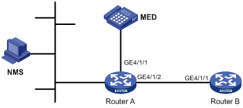
Network requirements
As shown in Figure 4, the NMS and Router A are located in the same Ethernet.
Enable LLDP on the ports of Router A and Router B to monitor the link between Router A and Router B and the link between Router A and the MED device on the NMS.
Configuration procedure
1. Configure Router A:
# Enable LLDP globally.
<RouterA> system-view
[RouterA] lldp enable
# Enable LLDP on GigabitEthernet 4/1/1 and GigabitEthernet 4/1/2 (you can skip this step because LLDP is enabled on ports by default), and set the LLDP operating mode to Rx.
[RouterA] interface gigabitethernet 4/1/1
[RouterA-GigabitEthernet4/1/1] lldp enable
[RouterA-GigabitEthernet4/1/1] lldp admin-status rx
[RouterA-GigabitEthernet4/1/1] quit
[RouterA] interface gigabitethernet 4/1/2
[RouterA-GigabitEthernet4/1/2] lldp enable
[RouterA-GigabitEthernet4/1/2] lldp admin-status rx
[RouterA-GigabitEthernet4/1/2] quit
2. Configure Router B:
# Enable LLDP globally.
<RouterB> system-view
[RouterB] lldp enable
# Enable LLDP on GigabitEthernet 4/1/1 (you can skip this step because LLDP is enabled on ports by default), and set the LLDP operating mode to Tx.
[RouterB] interface gigabitethernet 4/1/1
[RouterB-GigabitEthernet4/1/1] lldp enable
[RouterB-GigabitEthernet4/1/1] lldp admin-status tx
[RouterB-GigabitEthernet4/1/1] quit
3. Verify the configuration:
# Display the global LLDP status and port LLDP status on Router A.
[RouterA] display lldp status
Global status of LLDP : Enable
The current number of LLDP neighbors : 2
The current number of CDP neighbors: 0
LLDP neighbor information last changed time: 0 days,0 hours,4 minutes,40 seconds
Transmit interval : 30s
Hold multiplier : 4
Reinit delay : 2s
Transmit delay : 2s
Trap interval : 5s
Fast start times : 3
Port 1 [GigabitEthernet4/1/1]:
Port status of LLDP : Enable
Admin status : Rx_Only
Trap flag : No
Polling interval : 0s
Number of neighbors : 1
Number of MED neighbors : 1
Number of CDP neighbors : 0
Number of sent optional TLV : 0
Number of received unknown TLV : 0
Port 2 [GigabitEthernet4/1/2]:
Port status of LLDP : Enable
Admin status : Rx_Only
Trap flag : No
Polling interval : 0s
Number of neighbors : 1
Number of MED neighbors : 0
Number of CDP neighbors : 0
Number of sent optional TLV : 0
Number of received unknown TLV : 3
The output shows that: GigabitEthernet 4/1/1 of Router A connects a MED device, and GigabitEthernet 4/1/2 of Router A connects a non-MED device. Both ports operate in Rx mode, in other words, they only receive LLDP frames.
# Tear down the link between Router A and Router B and then display the global LLDP status and port LLDP status on Router A.
[RouterA] display lldp status
Global status of LLDP : Enable
The current number of LLDP neighbors : 1
The current number of CDP neighbors: 0
LLDP neighbor information last changed time: 0 days,0 hours,5 minutes,20 seconds
Transmit interval : 30s
Hold multiplier : 4
Reinit delay : 2s
Transmit delay : 2s
Trap interval : 5s
Fast start times : 3
Port 1 [GigabitEthernet4/1/1]:
Port status of LLDP : Enable
Admin status : Rx_Only
Trap flag : No
Polling interval : 0s
Number of neighbors : 1
Number of MED neighbors : 1
Number of CDP neighbors : 0
Number of sent optional TLV : 0
Number of received unknown TLV : 5
Port 2 [GigabitEthernet4/1/2]:
Port status of LLDP : Enable
Admin status : Rx_Only
Trap flag : No
Polling interval : 0s
Number of neighbors : 0
Number of MED neighbors : 0
Number of CDP neighbors : 0
Number of sent optional TLV : 0
Number of received unknown TLV : 0
The output shows that GigabitEthernet 4/1/2 of Router A does not connect any neighboring router.
CDP-compatible LLDP configuration example
Network requirements
As shown in Figure 5, enable CDP compatibility of LLDP on Router A.

Configuration procedure
1. Configure CDP-compatible LLDP on Router A:
# Enable LLDP globally and enable LLDP to be compatible with CDP globally.
[RouterA] lldp enable
[RouterA] lldp compliance cdp
# Enable LLDP (you can skip this step because LLDP is enabled on ports by default), configure LLDP to operate in TxRx mode, and configure CDP-compatible LLDP to operate in TxRx mode on GigabitEthernet 4/1/1 and GigabitEthernet 4/1/2.
[RouterA] interface gigabitethernet 4/1/1
[RouterA-GigabitEthernet4/1/1] lldp enable
[RouterA-GigabitEthernet4/1/1] lldp admin-status txrx
[RouterA-GigabitEthernet4/1/1] lldp compliance admin-status cdp txrx
[RouterA-GigabitEthernet4/1/1] quit
[RouterA] interface gigabitethernet 4/1/2
[RouterA-GigabitEthernet4/1/2] lldp enable
[RouterA-GigabitEthernet4/1/2] lldp admin-status txrx
[RouterA-GigabitEthernet4/1/2] lldp compliance admin-status cdp txrx
[RouterA-GigabitEthernet4/1/2] quit
2. Verify the configuration:
# Display the neighbor information on Router A.
[RouterA] display lldp neighbor-information
CDP neighbor-information of port 1[GigabitEthernet4/1/1]:
CDP neighbor index : 1
Chassis ID : SEP00141CBCDBFE
Port ID : Port 1
Sofrware version : P0030301MFG2
Platform : Cisco IP Phone 7960
Duplex : Full
CDP neighbor-information of port 2[GigabitEthernet4/1/2]:
CDP neighbor index : 2
Chassis ID : SEP00141CBCDBFF
Port ID : Port 1
Sofrware version : P0030301MFG2
Platform : Cisco IP Phone 7960
Duplex : Full
The output shows that Router A has discovered the IP phones connected to GigabitEthernet 4/1/1 and GigabitEthernet 4/1/2, and has obtained their LLDP device information.