- Table of Contents
-
- 03-Layer 2 - LAN Switching Configuration Guide
- 00-Preface
- 01-VLAN Configuration
- 02-MAC Address Table Configuration
- 03-Spanning Tree Configuration
- 04-Ethernet Link Aggregation Configuration
- 05-Port Isolation Configuration
- 06-QinQ Configuration
- 07-BPDU Tunneling Configuration
- 08-GVRP Configuration
- 09-VLAN Termination Configuration
- 10-LLDP Configuration
- Related Documents
-
| Title | Size | Download |
|---|---|---|
| 05-Port Isolation Configuration | 107.32 KB |
Contents
Introduction to port isolation
Configuring an isolation group
Assigning ports to an isolation group
Specifying the uplink port for an isolation group
Displaying and maintaining isolation groups
Port isolation configuration example
Introduction to port isolation
Assigning ports to different VLANs is a typical way to isolate Layer 2 traffic for data privacy and security, but this way is VLAN resource demanding. To save VLAN resources, you can use the port isolation feature, which can isolate ports without using VLANs and allows for great flexibility and security.
For the isolated ports to communicate with a port outside isolation groups at Layer 2, you must configure one uplink port for an isolation group.
The number of ports in an isolation group is not limited.
|
|
NOTE: · You cannot configure a link aggregation member port as the uplink port of an isolation group neither can you assign the uplink port of an isolation group to a link aggregation group. If a port is configured as a link aggregation member port and the uplink port of an isolation group at the same time, which is allowed with some old version software, the link aggregation group configuration will take effect while the port group configuration is removed for compatibility sake after you upgrade the configuration file. For more information about link aggregation, see the chapter “Configuring Ethernet link aggregation.” · Isolated ports only support MAC address learning, QoS actions accounting, filter deny, and car cir committed-information-rate red discard, and traffic mirroring in the incoming direction of the actions. · H3C does not recommend that you configure Layer 2 protocols (such as GVRP) or Layer 3 protocols (such as multicast and routing) on isolated ports. Doing so can cause forwarding anomaly or protocol flapping. |
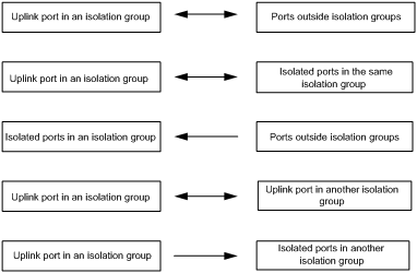
Layer 2 traffic cannot be forwarded between ports in different VLANs. However, the Layer 2 traffic from an isolated port can pass through the uplink port in the same isolation group unidirectionally even if they belong to different VLANs.
Figure 1 Communication between ports in the same VLAN in port isolation
|
|
NOTE: The arrows in the above figure indicate the move directions of Layer 2 traffic. |
Configuring an isolation group
Assigning ports to an isolation group
To assign ports to an isolation group:
|
Step |
Command |
Remarks |
|
1. Enter system view. |
system-view |
N/A |
|
2. Create an isolation group. |
port-isolate group group-number |
N/A |
|
3. Enter interface view or port group view. |
· Enter Ethernet interface view: · Enter port group view: · Enter Layer 2 aggregate interface view: |
Use one of the commands. · To assign Ethernet ports to the isolation group one by one, perform the command in Ethernet interface view. · To bulk assign Ethernet ports to the isolation group, perform the command in port group view. · The configuration in Layer 2 aggregate interface view applies to the Layer 2 aggregate interface and its aggregation member ports. If the router fails to apply the configuration to the aggregate interface, it does not assign any aggregation member port to the isolation group. If the failure occurs on an aggregation member port, the router skips the port and continues to assign other aggregation member ports to the isolation group. |
|
4. Assign ports to an isolation group as isolated ports. |
port-isolate enable group group-number |
No ports are assigned to any isolation group by default. |
Specifying the uplink port for an isolation group
To specify the uplink port for an isolation group:
|
Step |
Command |
Remarks |
|
1. Enter system view. |
System-view |
N/A |
|
2. Enter interface view. |
· Enter Ethernet interface view: · Enter Layer 2 aggregate interface view: |
Use either command. · The configuration in Ethernet interface view applies only to the port. · In Layer 2 aggregate interface view, only the Layer 2 aggregate interface is configured as the uplink port of the specified isolation group, and you can still assign its member ports as isolated ports. However, these ports will be placed in Unselected state and cannot receive or forward data packets. |
|
3. Configure the port as the uplink port of an isolation group. |
port-isolate uplink-port group group-number |
An isolation group has no uplink port by default. |
|
|
NOTE: · An isolation group can have only one uplink port. The uplink port you configured for an isolation group can overwrite the previous one, if any. · If you configure a common port in an isolation group as the common port of another isolation group, the port leaves the previous group and joins the new one. · You cannot configure an isolated port in an isolation group as the uplink port in any isolation group. · You cannot configure the uplink port of an isolation group as an isolated or uplink port in any other isolation group. · You cannot configure a link aggregation member port as the uplink port of an isolation group neither can you assign the uplink port of an isolation group to a link aggregation group. |
Displaying and maintaining isolation groups
|
Task |
Command |
Remarks |
|
Display the isolation group information. |
display port-isolate group [ group-number ] [ | { begin | exclude | include } regular-expression ] |
Available in any view |
Port isolation configuration example
Networking requirement
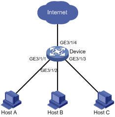
As shown in Figure 2:
· Device is connected to an external networks through GigabitEthernet 3/1/4.
· GigabitEthernet 3/1/1, GigabitEthernet 3/1/2, GigabitEthernet 3/1/3 and GigabitEthernet 3/1/4 belong to the same VLAN.
Configure that Host A, Host B, and Host C cannot exchange Layer 2 traffic with each other, but can access the external network.
Configuration procedure
# Create isolation group 2.
<Device> system-view
[Device] port-isolate group 2
# Add GigabitEthernet 3/1/1, GigabitEthernet 3/1/2, and GigabitEthernet 3/1/3 to isolation group 2 as isolated ports.
[Device] interface GigabitEthernet 3/1/1
[Device-GigabitEthernet3/1/1] port-isolate enable group 2
[Device-GigabitEthernet3/1/1] quit
[Device] interface GigabitEthernet 3/1/2
[Device-GigabitEthernet3/1/2] port-isolate enable group 2
[Device-GigabitEthernet3/1/2] quit
[Device] interface GigabitEthernet 3/1/3
[Device-GigabitEthernet3/1/3] port-isolate enable group 2
[Device-GigabitEthernet3/1/3] quit
# Configure GigabitEthernet 3/1/4 as the uplink port of isolation group 2.
[Device] interface GigabitEthernet 3/1/4
[Device-GigabitEthernet3/1/4] port-isolate uplink-port group 2
[Device-GigabitEthernet3/1/4] return
# Display information about isolation group 2.
<Device> display port-isolate group 2
Port-isolate group information:
Uplink port support: YES
Group ID: 2
Uplink port: GigabitEthernet3/1/4
Group members:
GigabitEthernet3/1/1 GigabitEthernet3/1/2 GigabitEthernet3/1/3
