- Table of Contents
-
- 03-Layer 2 - LAN Switching Configuration Guide
- 00-Preface
- 01-VLAN Configuration
- 02-MAC Address Table Configuration
- 03-Spanning Tree Configuration
- 04-Ethernet Link Aggregation Configuration
- 05-Port Isolation Configuration
- 06-QinQ Configuration
- 07-BPDU Tunneling Configuration
- 08-GVRP Configuration
- 09-VLAN Termination Configuration
- 10-LLDP Configuration
- Related Documents
-
| Title | Size | Download |
|---|---|---|
| 06-QinQ Configuration | 201.97 KB |
Contents
Modifying the TPID value in a VLAN tag
Setting the TPID value in VLAN tags
Basic QinQ configuration example
|
|
NOTE: In this documentation, SPC cards refer to the cards prefixed with SPC, for example, SPC-GT48L, and SPE cards refer to the cards prefixed with SPE, for example, SPE-1020-E-II. |
Introduction to QinQ
802.1Q in 802.1Q (QinQ) is a flexible, easy-to-implement Layer 2 VPN technology based on IEEE 802.1Q. It enables the edge router on the service provider network to encapsulate an outer VLAN tag in Ethernet frames from customer networks (private networks), so that the Ethernet frames will travel across the service provider network (public network) with double VLAN tags. QinQ enables a service provider to use a single provider network VLAN (SVLAN) to serve customers who have multiple customer network VLANs (CVLANs).
Background and benefits
The IEEE 802.1Q VLAN tag uses 12 bits for VLAN IDs. A network device supports a maximum of 4094 VLANs, which is far from enough for isolating users in actual networks, especially in metropolitan area networks (MANs).
By tagging tagged frames, QinQ expands the available VLAN space from 4094 to 4094 × 4094. QinQ delivers the following benefits:
· Releases the stress on the SVLAN resource.
· Enables customers to plan their CVLANs without conflicting with SVLANs.
· Provides an easy-to-implement Layer 2 VPN solution for small-sized MANs or intranets.
· Allows the customers to keep their current network configurations when the service provider upgrades the service provider network, thus making the customer networks more independent.
How QinQ works
The devices in the public network forward a frame only according to its outer VLAN tag and learn its source MAC address into the MAC address table of the outer VLAN. The inner VLAN tag of the frame is transmitted as payload.
|
|
NOTE: · All QinQ-related configurations are made on the service provider network only. · Because QinQ is based on the IEEE 802.1Q protocol, all network devices through which QinQ packets may pass must support the IEEE 802.1Q protocol. |
Figure 1 Schematic diagram of the QinQ feature
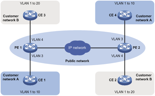
As shown in Figure 1, customer network A has CVLANs 1 through 10, while customer network B has CVLANs 1 through 20. The SVLAN allocated by the service provider for customer network A is SVLAN 3, and for customer network B is SVLAN 4. When a tagged Ethernet frame of customer network A enters the service provider network, it is tagged with outer VLAN 3; when a tagged Ethernet frame of customer network B enters the service provider network, it is tagged with outer VLAN 4. In this way, there is no overlap of VLAN IDs among customers, and traffic from different customers can be separated.
QinQ frame structure
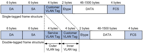
A QinQ frame is transmitted double-tagged over the service provider network. As shown in Figure 2, the inner VLAN tag is the CVLAN tag, and the outer one is the SVLAN tag that the service provider has allocated to the customer.
Figure 2 Single-tagged Ethernet frame header and double-tagged Ethernet frame header
|
|
NOTE: The default maximum transmission unit (MTU) of an interface is 1500 bytes. The size of an outer VLAN tag is 4 bytes. H3C recommends you to increase the MTU of each interface on the service provider network to at least 1504 bytes. For more information about interface MTU configuration, see Interface Configuration Guide. |
Implementations of QinQ
The router supports basic QinQ only.
Basic QinQ enables a port to tag any incoming frames with its port VLAN (PVID) tag, regardless of whether they have been tagged or not. If an incoming frame has been tagged, it becomes a double-tagged frame. If not, it becomes a frame tagged with the port’s PVID tag.
Modifying the TPID value in a VLAN tag
A VLAN tag uses the tag protocol identifier (TPID) field to identify the protocol type of the tag. The default TPID value is 0x8100.
Figure 3 VLAN Tag structure of an Ethernet frame
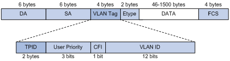
In addition, the systems of different vendors may set the TPID of the outer VLAN tag of QinQ frames to different values. For compatibility with these systems, you can modify the TPID value so that the QinQ frames, when sent to the public network, carry the TPID value identical to the value of a particular vendor to allow interoperability with network devices of that vendor.
The TPID in an Ethernet frame has the same position with the protocol type field in a frame without a VLAN tag. To avoid problems in packet forwarding and handling in the network, you cannot set the TPID value to any of the values in Table 1.
Table 1 Reserved protocol type values
|
Protocol type |
Value |
|
ARP |
0x0806 |
|
PUP |
0x0200 |
|
RARP |
0x8035 |
|
IP |
0x0800 |
|
IPv6 |
0x86DD |
|
PPPoE |
0x8863/0x8864 |
|
MPLS |
0x8847/0x8848 |
|
IPX/SPX |
0x8137 |
|
IS-IS |
0x8000 |
|
LACP |
0x8809 |
|
802.1x |
0x888E |
|
Cluster |
0x88A7 |
|
Reserved |
0xFFFD/0xFFFE/0xFFFF |
Protocols and standards
IEEE 802.1Q: IEEE standard for local and metropolitan area networks: Virtual Bridged Local Area Networks
QinQ configuration task list
Complete the follows tasks to configure QinQ:
|
Task |
Remarks |
|
Required |
|
|
Optional |
|
|
NOTE: · QinQ requires configurations only on the service provider network. · Do not configure QinQ on a reflector port. For more information about reflector ports, see Network Management and Monitoring Configuration Guide. |
Configuring basic QinQ
To enable basic QinQ:
|
Step |
Command |
Remarks |
|
1. Enter system view. |
system-view |
N/A |
|
2. Enter interface view or port group view. |
·
Enter Layer 2 Ethernet interface view or Layer 2
aggregate interface view: ·
Enter port group view: |
Use either command. |
|
3. Enable QinQ on the port(s). |
qinq enable |
By default, QinQ is disabled. |
|
|
NOTE: Configure basic QinQ on the user-to-network interfaces (UNIs) on service provider network devices that connect the user networks. |
Setting the TPID value in VLAN tags
To set the TPID value in outer VLAN tags:
|
Step |
Command |
Remarks |
|
1. Enter system view. |
system-view |
N/A |
|
2. Enter interface view or port group view. |
·
Enter Layer 2 Ethernet interface view or Layer 2
aggregate interface view: ·
Enter port group view: |
Use either command. |
|
3. Set the TPID value in outer VLAN tags. |
qinq ethernet-type hex-value |
Optional. The default setting is 0x8100. |
|
|
NOTE: To change a non-default TPID value to another non-default TPID value, you must first restore the default TPID value (0x8100) on an SPE card, but you can directly change the TPID value on an SPC card. |
Basic QinQ configuration example
Network requirements
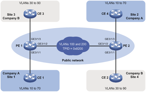
As shown in Figure 4:
· The two branches of Company A, Site 1 and Site 2, are connected through the service provider network and use CVLANs 10 through 70. The two branches of Company B, Site 3 and Site 4, are connected through the service provider network and use CVLANs 30 through 90.
· PE 1 and PE 2 are edge devices on the service provider network and are connected through third-party devices with a TPID value of 0x8200.
Configure the edge and third-party devices to enable communication between the branches of Company A through SVLAN 100, and communication between the branches of Company B through SVLAN 200.
Configuration procedure
|
|
NOTE: Make sure that the devices in the service provider network have been configured to allow QinQ packets to pass through. |
1. Configure PE 1:
# Configure GigabitEthernet 3/1/1 as a trunk port and assign it to VLAN 100 and VLANs 10 through 70.
<PE1> system-view
[PE1] interface GigabitEthernet 3/1/1
[PE1-GigabitEthernet3/1/1] port link-type trunk
[PE1-GigabitEthernet3/1/1] port trunk permit vlan 100 10 to 70
# Configure VLAN 100 as the PVID for the port.
[PE1-GigabitEthernet3/1/1] port trunk pvid vlan 100
# Enable basic QinQ on the port.
[PE1-GigabitEthernet3/1/1] qinq enable
[PE1-GigabitEthernet3/1/1] quit
# Configure GigabitEthernet 3/1/2 as a trunk port and assign it to VLAN 100 and VLAN 200.
[PE1] interface GigabitEthernet 3/1/2
[PE1-GigabitEthernet3/1/2] port link-type trunk
[PE1-GigabitEthernet3/1/2] port trunk permit vlan 100 200
# Set the TPID value in the outer VLAN tag to 0x8200 on the port.
[PE1-GigabitEthernet3/1/2] qinq ethernet-type 8200
[PE1-GigabitEthernet3/1/2] quit
# Configure GigabitEthernet 3/1/3 as a trunk port and assign it to VLAN 200 and VLANs 30 through 90.
[PE1] interface GigabitEthernet 3/1/3
[PE1-GigabitEthernet3/1/3] port link-type trunk
[PE1-GigabitEthernet3/1/3] port trunk permit vlan 200 30 to 90
# Configure VLAN 200 as the PVID for the port.
[PE1-GigabitEthernet3/1/3] port trunk pvid vlan 200
# Enable basic QinQ on the port.
[PE1-GigabitEthernet3/1/3] qinq enable
[PE1-GigabitEthernet3/1/3] quit
2. Configure PE 2:
# Configure GigabitEthernet 3/1/1 as a trunk port and assign it to VLAN 200 and VLANs 30 through 90.
<PE2> system-view
[PE2] interface GigabitEthernet 3/1/1
[PE2-GigabitEthernet3/1/1] port link-type trunk
[PE2-GigabitEthernet3/1/1] port trunk permit vlan 200 30 to 90
# Configure VLAN 200 as the PVID for the port.
[PE2-GigabitEthernet3/1/1] port trunk pvid vlan 200
# Enable basic QinQ on the port.
[PE2-GigabitEthernet3/1/1] qinq enable
[PE2-GigabitEthernet3/1/1] quit
# Configure GigabitEthernet 3/1/2 as a trunk port and assign it to VLAN 100 and VLAN 200.
[PE2] interface GigabitEthernet 3/1/2
[PE2-GigabitEthernet3/1/2] port link-type trunk
[PE2-GigabitEthernet3/1/2] port trunk permit vlan 100 200
# Set the TPID value in the outer VLAN tag to 0x8200 on the port.
[PE2-GigabitEthernet3/1/2] qinq ethernet-type 8200
[PE2-GigabitEthernet3/1/2] quit
# Configure GigabitEthernet 3/1/3 as a trunk port and assign it to VLAN 100 and VLANs 10 through 70.
[PE2] interface GigabitEthernet 3/1/3
[PE2-GigabitEthernet3/1/3] port link-type trunk
[PE2-GigabitEthernet3/1/3] port trunk permit vlan 100 10 to 70
# Configure VLAN 100 as the PVID for the port.
[PE2-GigabitEthernet3/1/3] port trunk pvid vlan 100
# Enable basic QinQ on the port.
[PE2-GigabitEthernet3/1/3] qinq enable
[PE2-GigabitEthernet3/1/3] quit
3. Configure third-party devices:
On the third-party devices between PE 1 and PE 2, configure the port connecting to PE 1 and that connecting to PE 2 to allow tagged frames of VLAN 100 and VLAN 200 to pass through.
