- Table of Contents
-
- 03-Layer 2 - LAN Switching Configuration Guide
- 00-Preface
- 01-VLAN Configuration
- 02-MAC Address Table Configuration
- 03-Spanning Tree Configuration
- 04-Ethernet Link Aggregation Configuration
- 05-Port Isolation Configuration
- 06-QinQ Configuration
- 07-BPDU Tunneling Configuration
- 08-GVRP Configuration
- 09-VLAN Termination Configuration
- 10-LLDP Configuration
- Related Documents
-
| Title | Size | Download |
|---|---|---|
| 07-BPDU Tunneling Configuration | 135.92 KB |
Contents
Introduction to BPDU tunneling
Enabling BPDU tunneling for a protocol
Configuring destination multicast MAC address for BPDUs
BPDU tunneling configuration example
Introduction to BPDU tunneling
As a Layer 2 tunneling technology, BPDU tunneling enables Layer 2 protocol packets from geographically dispersed customer networks to be transparently transmitted over specific tunnels across a service provider network.
Background
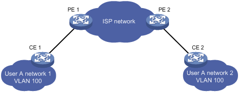
Dedicated lines are used in a service provider network to build user-specific Layer 2 networks. As a result, a user network is broken down into parts located at different sides of the service provider network. As shown in Figure 1, User A has two devices (CE 1 and CE 2) and both devices belong to VLAN 100. User A’s network is divided into network 1 and network 2, which are connected by the service provider network. When a Layer 2 protocol (for example, STP) runs on both network 1 and network 2, the Layer 2 protocol packets must be transmitted over the service provider network to implement Layer 2 protocol calculation (for example, spanning tree calculation). When receiving a Layer 2 protocol packet, the PEs cannot determine whether the packet is from the user network or the service provider network, and must deliver the packet to the CPU for processing. In this case, the Layer 2 protocol calculation in User A’s network is mixed with that in the service provider network, and the user network cannot implement independent Layer 2 protocol calculation.
Figure 1 BPDU tunneling application scenario
With BPDU tunneling, Layer 2 protocol packets from customer networks can be transparently transmitted over the service provider network in the following workflow:
1. After receiving a Layer 2 protocol packet from CE 1, PE 1 in the service provider network encapsulates the packet, replaces its destination MAC address with a specific multicast MAC address, and then forwards the packet in the service provider network;
2. The encapsulated Layer 2 protocol packet (called bridge protocol data unit, BPDU) is forwarded to PE 2 at the other end of the service provider network, which de-encapsulates the packet, restores the original destination MAC address of the packet, and then sends the packet to CE 2.
|
|
NOTE: BPDU tunneling supports the transparent transmission of the Spanning Tree Protocol (STP) packets. |
BPDU Tunneling implementation
|
|
NOTE: · The term STP in this document is in a broad sense. It includes STP, RSTP, and MSTP. · STP calculates the topology of a network by transmitting BPDUs among bridges in the network. For details, see the chapter “Configuring the spanning tree.” |
To avoid loops in your network, you can enable STP on your routers. When the topology changes at one side of the customer network, the routers at this side of the customer network send BPDUs to routers on the other side of the customer network, thus ensuring consistent spanning tree calculation in the entire customer network. However, because BPDUs are Layer 2 multicast frames, all STP-enabled routers, both in the customer network and in the service provider network, can receive and process these BPDUs. In this case, neither the service provider network nor the customer network can correctly calculate its independent spanning tree.
To allow each network to calculate an independent spanning tree with STP, BPDU tunneling was introduced.
BPDU tunneling delivers the following benefits:
· BPDUs can be transparently transmitted. BPDUs of the same customer network can be broadcast in a specific VLAN across the service provider network, so that the geographically dispersed networks of the same customer can implement consistent spanning tree calculation across the service provider network.
· BPDUs of different customer networks can be confined within different VLANs for transmission on the service provider network. Thus, each customer network can perform independent spanning tree calculation.
Figure 2 BPDU tunneling implementation
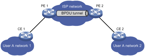
As shown in Figure 2, the upper part is the service provider network (ISP network), and the lower part represents two different parts of a customer network: User A network 1 and User A network 2. Enabling the BPDU tunneling function on the edge routers (PE 1 and PE 2) in the service provider network allows BPDUs of the customer network to be transparently transmitted in the service provider network, thus ensuring consistent spanning tree calculation of User A network, without affecting the spanning tree calculation of the service provider network.
Assume a BPDU is sent from User A network 1 to User A network 2:
1. At the ingress of the service provider network, PE 1 changes the destination MAC address of the BPDU from 0x0180-C200-0000 to a special multicast MAC address, 0x010F-E200-0003 (the default multicast MAC address) for example. In the service provider network, the modified BPDU is forwarded as a data packet in the VLAN assigned to User A.
2. At the egress of the service provider network, PE 2 recognizes the BPDU with the destination MAC address 0x010F-E200-0003, restores its original destination MAC address 0x0180-C200-0000, and then sends the BPDU to CE 2.
|
|
NOTE: Make sure, through configuration, that the VLAN tags carried in BPDUs are neither changed nor removed during the transparent transmission in the service provider network; otherwise, the routers in the service provider network will fail to transparently transmit the customer network BPDUs correctly. |
Configuring BPDU tunneling
Configuration prerequisites
· Before configuring BPDU tunneling for STP, enable STP in the customer network first.
· Before enabling BPDU tunneling for STP on a port, disable STP on the port first.
· Assign the port on which you want to enable BPDU tunneling on the PE router and the connected port on the CE router to the same VLAN.
· Configure ports connecting routers in the service provider network as trunk ports allowing packets of any VLAN to pass through.
Enabling BPDU tunneling for a protocol
This section describes how to enable BPDU tunneling for STP. You can enable BPDU tunneling for GVRP in a similar way.
To enable BPDU tunneling for STP:
|
Step |
Command |
Remarks |
|
1. Enter system view. |
system-view |
N/A |
|
2. Enter interface view or port group view. |
·
Enter Layer 2 Ethernet interface view: · Enter Layer 2 aggregate interface view: · Enter port group view: |
Use any command. Settings made in Layer 2 Ethernet/aggregate interface view take effect only on the current port. Settings made in port group view take effect on all ports in the port group. |
|
3. Disable STP. |
stp disable |
N/A |
|
4. Enable BPDU tunneling for STP. |
bpdu-tunnel dot1q stp |
By default, BPDU tunneling is disabled for STP. |
Configuring destination multicast MAC address for BPDUs
By default, the destination multicast MAC address for BPDUs is 0x010F-E200-0003. You can change it to 0x0100-0CCD-CDD0, 0x0100-0CCD-CDD1 or 0x0100-0CCD-CDD2 through the following configuration.
To configure the destination multicast MAC address for BPDUs:
|
Step |
Command |
Remarks |
|
1. Enter system view. |
system-view |
N/A |
|
2. Configure the destination multicast MAC address for BPDUs. |
bpdu-tunnel tunnel-dmac mac-address |
Optional. The default setting is 0x010F-E200-0003. |
|
|
NOTE: For BPDUs to be recognized, the destination multicast MAC addresses configured for BPDUs must be the same on the edge routers on the service provider network. |
BPDU tunneling configuration example
Network requirements
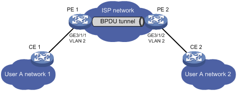
As shown in Figure 3:
· CE 1 and CE 2 are edges routers on the geographically dispersed network of User A; PE 1 and PE 2 are edge routers on the service provider network.
· All ports that connect service provider and customer routers are access ports and belong to VLAN 2; all ports that connect service provider routers are trunk ports and allow packets of any VLAN to pass through.
· MSTP is enabled on User A network.
Configure BPDU tunneling, so that CE 1 and CE 2 implement consistent spanning tree calculation across the service provider network and the destination multicast MAC address in BPDUs is 0x0100-0CCD-CDD0.
Configuration procedure
1. Configure PE 1:
# Configure the destination multicast MAC address for BPDUs as 0x0100-0CCD-CDD0.
<Sysname> system-view
[Sysname] bpdu-tunnel tunnel-dmac 0100-0ccd-cdd0
# Create VLAN 2 and assign GigabitEthernet 3/1/1 to VLAN 2.
[Sysname] vlan 2
[Sysname-vlan2] quit
[Sysname] interface GigabitEthernet 3/1/1
[Sysname-GigabitEthernet3/1/1] port access vlan 2
# Disable STP on GigabitEthernet 3/1/1, and then enable BPDU tunneling for STP on it.
[Sysname-GigabitEthernet3/1/1] stp disable
[Sysname-GigabitEthernet3/1/1] bpdu-tunnel dot1q stp
2. Configure PE 2:
# Configure the destination multicast MAC address for BPDUs as 0x0100-0CCD-CDD0.
<Sysname> system-view
[Sysname] bpdu-tunnel tunnel-dmac 0100-0ccd-cdd0
# Create VLAN 2 and assign GigabitEthernet 3/1/2 to VLAN 2.
[Sysname] vlan 2
[Sysname-vlan2] quit
[Sysname] interface gigabitethernet 3/1/2
[Sysname-GigabitEthernet3/1/2] port access vlan 2
# Disable STP on GigabitEthernet 3/1/2, and then enable BPDU tunneling for STP on it.
[Sysname-GigabitEthernet3/1/2] stp disable
[Sysname-GigabitEthernet3/1/2] bpdu-tunnel dot1q stp
