- Table of Contents
- Related Documents
-
| Title | Size | Download |
|---|---|---|
| 05-E-CPOS Interface Configuration | 217.92 KB |
Contents
Configuring an E-CPOS interface
Configuring an E-CPOS interface
Configuring the operating mode of an E-CPOS interface/channel
Displaying and maintaining E-CPOS interfaces
E-CPOS interface configuration example
Troubleshooting E-CPOS interfaces
Overview
SONET
Synchronous Optical Network (SONET), a synchronous transmission system defined by the ANSI, is an international standard transmission protocol over fiber-optic. SONET transmission rates form a sequence of OC-1 (51.84 Mbps), OC-3 (155 Mbps), OC-12 (622 Mbps), and OC-48 (2.5 Gbps). Because signals are synchronous, SONET can multiplex signals conveniently.
SDH
Synchronous Digital Hierarchy (SDH), defined by the CCITT (today’s ITU-T) uses a SONET rate subset. As SDH adopts synchronous multiplexing and allows for flexible mapping, low-speed tributary signals can be added to or dropped from SDH signals without a large number of multiplexing/demultiplexing devices. This reduces signal attenuation and investment in network devices.
SDH frame structure
Low-speed tributary signals should distribute in a frame regularly and evenly for the convenience of adding them to or dropping them from high-speed signals. The ITU-T stipulates that STM-N frames adopt the structure of rectangle blocks in bytes, as shown in Figure 1:
Figure 1 STM-N frame structure
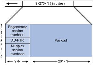
STM-N is a rectangle-block frame structure of 9 rows x 270 x N columns, where the N in STM-N equals the N columns. N takes the value 1, 4, 16, and so on, indicating the number of STM-1 signals that form SDH signal.
The STM-N frame structure consists of three parts: the section overhead (SOH), which includes the regenerator section overhead (RSOH) and the multiplex section overhead (MSOH); the administration unit pointer (AU-PTR); and payload. AU-PTR is the pointer that indicates the location of the first byte of the payload in an STM-N frame so that the receiving end can correctly extract the payload.
Multiplexing STM frames
An STM-1 frame adopts the rectangular structure of 270 columns and 9 rows, with the first 10 columns as the overhead and the rest 260 columns as the payload. An STM-N frame is formed by interleaving N STM-1 frames.
Figure 2 STM-1 frame structure
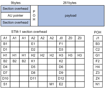
· SOH—The SDH section overhead. It is used for monitoring the entire STM-1 frame and does not carry user data. The SOH consists of the regenerator section overhead (RSOH) and the multiplex section overhead (MSOH). For example, B1 and B2 are used for bit error rate test (BERT) for the frame; A1 and A2 are frame synchronization bytes.
· AU-PTR—The administration unit pointer. It indicates the location of the payload in the STM-1 frame.
· POH—Path overhead. It is used for monitoring the payload. For example, the C2 byte in the POH indicates the payload type, and the G1 byte of the POH indicates whether a bit error is present in the payload.
· Payload—If channelization stops, the payload carries user data; if channelization continues, the payload carries the data of multiplexed lower-order channels.
The following figure shows how four STM-1 frames are multiplexed into an STM-4 frame. In the same way, four STM-4 frames can be multiplexed into an STM-16 frame.
Figure 3 Process of multiplexing four STM-1 frames into an STM-4 frame
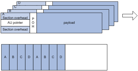
The recipient will demultiplex a received STM-4 frame into four STM-1 frames. During the multiplexing process, the A1, A2, J0, Z0, B1, E1, F1, D1, D2, and D3 fields in the RSOH of the first frame are multiplexed into the STM-4 frame while those of the rest three frames are treated as invalid. The other fields of each frame are multiplexed into the STM-4 frame separately.
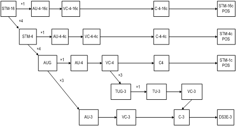
Figure 4 shows how an STM-16 frame in the SDH frame format is demultiplexed.
Figure 4 The process of demultiplexing an STM-16 frame in the SDH frame format
Rate hierarchy of SONET/SDH
SDH frames at different rates are identified in the form of STM-N (N equals 1, 4, 16, 64, and so on, indicating that the frame is formed through multiplexing and interleaving N STM-1 frames). SONET frames at different rates are identified in the form of STS-N (N equals 1, 3, 12, 48, and so on, indicating that the frame is formed through multiplexing and interleaving N STS-1 frames. The following table lists the rate hierarchies of SONET and SDH.
Table 1 Rate hierarchy of SONET/SDH
|
SONET |
SDH |
Rate |
|
STS-1 |
N/A |
51.840 Mbps |
|
STS-3 |
STM-1 |
155.52 Mbps |
|
STS-12 |
STM-4 |
622.080 Mbps |
|
STS-48 |
STM-16 |
2488.320 Mbps |
Overhead bytes
SDH provides hierarchical monitoring and management functions. It provides section level monitoring and path level monitoring. Section level monitoring is subdivided into regenerator section level monitoring and multiplex section level monitoring, while the path level monitoring is subdivided into higher-order path level monitoring and lower-order path level monitoring. These monitoring functions are implemented using overhead bytes.
|
|
NOTE: SDH provides a variety of overhead bytes, but only those involved in E-CPOS configuration are discussed in this section. |
· SOH
The SOH consists of the RSOH and the MSOH.
The regeneration section trace message J0 is included in the RSOH to send the section access point identifier repeatedly. Based on the identifier, the receiver can make sure that it is in continuous connection with the sender. This byte can be any character in the network of the same operator. If the networks of two operators are involved, the sending and receiving devices at network borders must use the same J0 byte. With the J0 byte, operators can detect and troubleshoot faults in advance or use less time to recover networks.
· POH
The payload of an STM-N frame includes the path overhead (POH), which monitors low-speed tributary signals.
While the SOH monitors the section layer, the POH monitors the path layer. The POH is divided into the higher-order path overhead and the lower-order path overhead.
The higher-order path overhead monitors lower-level paths.
Similar to the J0 byte, the higher-order VC-N path trace byte J1 is included in the higher-order path overhead to send the higher-order path access point identifier repeatedly. Based on the identifier, the receiving end of the path can make sure that it is in continuous connection with the specified sending end. The sender and the recipient must use the same J1 byte.
In addition, the path signal label byte C2 is included in the higher-order path overhead to indicate the multiplexing structure of VC frames and the properties of payload such as whether the path is carrying services, what type of services are carried, and how they are mapped. The sender and the recipient must use the same C2 byte.
Terms
· Multiplex unit—A basic SDH multiplex unit includes containers (C-n), virtual containers (VC-n), tributary units (TU-n), tributary unit groups (TUG-n), administrative units (AU-n), and administrative unit groups (AUG-n), where n is the unit level sequence number.
· Container—Information structure unit that carries service signals at different rates. G.709 defines the criteria for five standard containers: C-11, C-12, C-2, C-3 and C-4.
· Virtual container (VC)—Information structure unit supporting path level connection of SDH. It terminates an SDH path. VCs are divided into lower-order and higher-order VCs. VC-3 in AU-3 and VC-4 are higher-order VCs.
· Tributary unit (TU) and tributary unit group (TUG)—TU is the information structure that provides adaptation between higher-order paths and lower-order paths. TUG is a set of one or more TUs whose locations are fixed in higher-order VC payload.
· Administrative unit (AU) and administrative unit group (AUG)—AU is the information structure that provides adaptation between the higher-order path layer and the multiplex section layer. AUG is a set of one or more AUs whose locations are fixed in the STM-N payload.
· Optical carrier (OC)—OC is a series of physical protocols (including OC-1, OC-2, and so on) defined for optical transmission over an SONET network. The number in an OC level corresponds to a rate for STS frames. The base rate is 51.84 Mbps (OC-1), the rate of OC-3 is 155.52 Mbps, and so on.
E-CPOS
The low-speed tributary signals multiplexed to form an SDH signal are called channels. A channelized POS (CPOS) interface makes full use of SDH to provide precise bandwidth division, reduce the number of low-speed physical interfaces on network devices, enhance their distribution capacity, and improve the access capacity of dedicated lines.
The basic functions of enhanced CPOS (E-CPOS) interfaces and CPOS interfaces are the same but their port rate hierarchies and channelization levels are different. For more information, see “Configuring the operating mode of an E-CPOS interface/channel.”
Channelized and unchannelized
· A channelized POS interface uses the low-speed tributary signals of STM-N to transmit multiple streams of data independent of one another over an optical fiber. Each data stream shares separate bandwidth and has its own start point, end point, and monitoring policy. They are called channels.
· An unchannelized POS interface uses all STM-N signals to transmit a stream of data over an optical fiber. The transmitted data has the same identifier, start point, and end point, and is regulated by the same monitoring policy.
When multiple streams of low-speed signals are to be transmitted, channelization can make better use of bandwidth. When a single high-speed stream of data is to be transmitted, the unchannelized mode is recommended.
Operating modes of E-CPOS interfaces
An E-CPOS interface can operate in channelized mode or concatenated mode:
· In channelized mode, a higher-order STM-N frame is regarded as being formed by four lower-order STM-N frames through time-division multiplexing. In this case, a higher-order STM-N frame will be demultiplexed into multiple lower-order STM-N frames for processing.
· In concatenated mode, STM-N frames are processed without being demultiplexed.
E-CPOS interface application scenario
E-CPOS enhances the capability of network devices in low-speed access redistribution. STM-1 E-CPOS is especially suitable for aggregating E3/T3 channels. As shown in Figure 5, some government agencies and enterprises use low-end and mid-range routers to access the transmission network through E3/T3 leased lines. Users who require bandwidth between E3 and T3, for a data center for example, lease multiple E3/T3 lines. The bandwidth of all these users is aggregated to one or more CPOS interfaces through the transmission network, and then connected to a high-end router where the low-end routers are uniquely identified by timeslots.
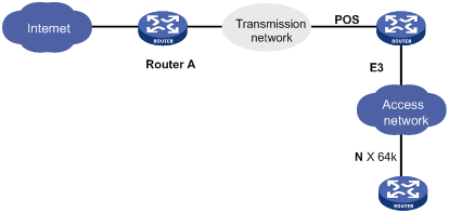
In actual applications, the connection between these low-end routers and the E-POS interfaces may span more than one transmission network and as such, may require relay. This is similar to the scenario where low-end network devices are connected to Router A through one or multiple E3/T3 leased lines.
Configuring an E-CPOS interface
Complete the following tasks to configure an E-CPOS interface:
· Configuring an E-CPOS interface
· Configuring the operating mode of an E-CPOS interface/channel
Configuring an E-CPOS interface
To configure an E-CPOS interface:
|
Step |
Command |
Remarks |
|
1. Enter system view. |
system-view |
N/A |
|
2. Enter E-CPOS interface view. |
controller e-cpos interface-number |
N/A |
|
3. Set the interface description. |
description text |
Optional. By default, the description of an E-CPOS interface is interface name Interface, for example, E-Cpos7/1/6 Interface. |
|
4. Set the framing format. |
frame-format { sdh | sonet } |
Optional. SDH by default. |
|
5. Configure the clocking mode. |
clock { master | slave } |
Optional. Slave clocking mode by default. |
|
6. Configure the loopback mode. |
loopback { local | remote } |
Optional. Disabled by default. |
|
7. Configure the AUG multiplexing path. |
multiplex mode { au-3 | au-4 } |
Optional. AU-4 for SDH, and AU-3 for SONET by default. Only subcards PIC-CLS4G4L and PIC-CHS1G4L support this command. |
|
8. Configure the J0 byte. |
flag j0 { sdh j0-string | sonet j0-value } |
Optional. |
|
9. Configure the signal degrade (SD) threshold and signal fail (SF) threshold. |
threshold { sd | sf } value |
Optional. By default, the SD threshold is 10e-6 and the SF threshold is 10e-3. |
|
10. Restore the default settings. |
default |
Optional. |
|
11. Shut down the E-CPOS interface. |
shutdown |
Optional. Up by default. |
|
|
NOTE: · If no cable is connected to a physical interface, shut down the interface with the shutdown command to prevent anomalies caused by interference. · Use the shutdown command with caution, because once an interface is shut down, it stops operating. |
Configuring the operating mode of an E-CPOS interface/channel
As mentioned earlier, E-CPOS interfaces are different from CPOS interfaces in rate hierarchy and channelization hierarchy. The major types of E-CPOS interfaces supported currently include:
· STM-16 E-CPOS interfaces (at 2488 Mbps), which can be channelized into 2.5 Gbps/622 Mbps/155 Mbps POS channels.
· STM-4 E-CPOS interfaces (at 622 Mbps), which can be channelized into 622 Mbps/155 Mbps POS channels or E3/T3 serial interfaces.
· STM-1 E-CPOS interfaces (at 155 Mbps), which can be channelized into 155 Mbps POS channels or E3/T3 serial interfaces.
Configuring the interface/channel operating mode on a 2.5 Gbps E-CPOS interface
You can use the using command to configure a 2.5 Gbps E-CPOS interface to operate in channelized mode or concatenated mode.
To create POS channels, configure the concatenated mode. On a 2.5 Gbps E-CPOS interface in concatenated mode, you can create sixteen 155 Mbps channels, four 622 Mbps channels, or one 2.5 Gbps POS channel.
1. Configure the operating mode of a 2.5 Gbps E-CPOS interface
To create a 2.5 Gbps POS channel and configure its operating mode on a 2.5 Gbps E-CPOS interface:
|
Step |
Command |
Remarks |
|
1. Enter system view. |
system-view |
N/A |
|
2. Enter E-CPOS interface view. |
controller e-cpos interface-number |
N/A |
|
3. Configure the 2.5 Gbps E-CPOS interface to operate in concatenated mode. |
using oc-48c |
The default is the channelized mode. |
2. Create a 622 Mbps POS channel and configure its operating mode
To create a 622 Mbps POS channel and configure its operating mode on a 2.5 Gbps E-CPOS interface:
|
Step |
Command |
Remarks |
|
1. Enter system view. |
system-view |
N/A |
|
2. Enter E-CPOS interface view. |
controller e-cpos interface-number |
N/A |
|
3. Configure the 2.5 Gbps E-CPOS interface to operate in channelized mode. |
using oc-48 |
Optional. By default, a 2.5 Gbps E-CPOS interface operates in channelized mode. Before creating a 622 Mbps POS channel, you must configure the 2.5 Gbps E-CPOS interface to operate in channelized mode. |
|
4. Create a 622 Mbps channel and enter its view. |
oc-12 oc-12-number |
N/A |
|
5. Configure the 622 Mbps channel to operate in concatenated mode. |
using oc-12c |
The default is the channelized mode. |
3. Create a 155 Mbps POS channel and configure its operating mode
To create a 155 Mbps POS channel and configure its operating mode on a 2.5 Gbps E-CPOS interface:
|
Step |
Command |
Remarks |
|
1. Enter system view. |
system-view |
N/A |
|
2. Enter E-CPOS interface view. |
controller e-cpos interface-number |
N/A |
|
3. Create a 622 Mbps channel and enter its view. |
oc-12 oc-12-number |
N/A |
|
4. Configure the 622 Mbps E-CPOS interface to operate in channelized mode |
using oc-12 |
Optional. By default, a 622 Mbps E-CPOS interface operates in channelized mode. Before creating a 155 Mbps POS channel, you must configure the 2.5 Gbps E-CPOS interface to operate in channelized mode. |
|
5. Create a 155 Mbps channel and enter its view. |
oc-3 oc-3-number |
N/A |
|
6. Configure the 155 Mbps channel to operate in concatenated mode. |
using oc-3c |
Channelized mode by default. |
Configuring the interface/channel operating mode on a 622 Mbps E-CPOS interface
Use the using command to configure a 622 Mbps E-CPOS interface to operate in channelized mode or concatenated mode:
· To create POS channels, configure the concatenated mode. On a 622 Mbps E-CPOS interface in concatenated mode, you can create four 155 Mbps or one 622 Mbps POS interface.
· To create E3 or T3 channels, configure the channelized mode.
1. Configure the operating mode of a 622 Mbps E-CPOS interface
To create a 622 Mbps POS channel and configure its operating mode on a 622 Mbps E-CPOS interface:
|
Step |
Command |
Remarks |
|
1. Enter system view. |
system-view |
N/A |
|
2. Enter 622 Mbps E-CPOS interface view. |
controller e-cpos interface-number |
N/A |
|
3. Configure the interface to operate in concatenated mode. |
using { oc-12 | oc-12c } |
The default is the channelized mode. |
2. Create a 155 Mbps POS channel and configure its operating mode
To create a 155 Mbps POS channel and configure its operating mode on a 622 Mbps E-CPOS interface:
|
Step |
Command |
Remarks |
|
1. Enter system view. |
system-view |
N/A |
|
2. Enter 622 Mbps E-CPOS interface view. |
controller e-cpos interface-number |
N/A |
|
3. Create a 155 Mbps channel and enter its view. |
oc-3 oc-3-number |
N/A |
|
4. Configure the 155 Mbps channel to operate in concatenated mode. |
using { oc-3 | oc-3c } |
Optional. The default is the channelized mode. |
3. Create an E3/T3 channel and configure its operating mode
To create an E3/T3 channel and configure its operating mode on a 622 Mbps E-CPOS interface:
|
Step |
Command |
Remarks |
|
1. Enter system view. |
system-view |
N/A |
|
2. Enter 622 Mbps E-CPOS interface view. |
controller e-cpos interface-number |
N/A |
|
3. Enter OC-3 view (the view of a 155 Mbps channel). |
oc-3 oc-3-number |
N/A |
|
4. Configure the operating mode of the E3/T3 channel. |
· Configure the E3 channel to operate in unframed mode: · Configure the T3 channel to operate in unframed mode: |
Use either approach. By default, no E3/T3 channel is created. |
Configuring the operating mode for a 155 Mbps E-CPOS interface
You can use the using command to configure a 155 Mbps E-CPOS interface to operate in channelized mode or concatenated mode.
· To create POS channels, configure the concatenated mode. On a 155 Mbps E-CPOS interface in concatenated mode, you can create one 155 Mbps POS interface.
· To create E3 or T3 channels, configure the channelized mode.
1. Configure the operating mode of a 155 Mbps E-CPOS interface
To configure the operating mode of a 155 Mbps E-CPOS interface:
|
Step |
Command |
Remarks |
|
1. Enter system view. |
system-view |
N/A |
|
2. Enter E-CPOS interface view. |
controller e-cpos interface-number |
N/A |
|
3. Configure the 155 Mbps E-CPOS interface to operate in concatenated mode. |
using { oc-3 | oc-3c } |
The default is the channelized mode. |
2. Create an E3/T3 channel and configure its operating mode
To configure the operating mode of an E3/T3 channel on a 155 Mbps E-CPOS interface:
|
Step |
Command |
Remarks |
|
1. Enter system view. |
system-view |
N/A |
|
2. Enter 155 Mbps E-CPOS interface view. |
controller e-cpos interface-number |
N/A |
|
3. Configure the 155 Mbps E-CPOS interface to operate in channelized mode. |
using { oc-3 | oc-3c } |
The default is the channelized mode. |
|
4. Configure the operating mode for the E3/T3 channel. |
· Configure the E3 channel to operate in unframed mode: · Configure the T3 channel to operate in unframed mode: |
Use either approach. By default, no E3/T3 channel is created. |
|
|
NOTE: · oc-48 and oc-48c correspond to 2.5 Gbps E-CPOS interfaces. · oc-12 and oc-12c correspond to 622 Mbps E-CPOS interfaces or 622 Mbps channels channelized from 2.5 Gbps E-CPOS interfaces. · oc-3 and oc-3c correspond to 155 Mbps E-CPOS interfaces or 155 Mbps channels channelized from 2.5 Gbps E-CPOS interfaces or 622 Mbps E-CPOS interfaces. |
Displaying and maintaining E-CPOS interfaces
|
Task |
Command |
Remarks |
|
Display information about all channels of the specified E-CPOS interface. |
display controller e-cpos [ e-cpos-number ] [ | { begin | exclude | include } regular-expression ] |
Available in any view |
|
Display information about the E3/T3 channels of the specified E-CPOS interface. |
display interface serial [ interface-number:set-number ] [ | { begin | exclude | include } regular-expression ] |
Available in any view |
|
Display information about the POS channels of the specified E-CPOS interface. |
display interface pos [ interface-number ] [ | { begin | exclude | include } regular-expression ] |
Available in any view |
|
Clear the controller counter of the specified E-CPOS interface. |
reset counters controller e-cpos interface-number |
Available in user view |
|
|
NOTE: For more information about the display interface serial command, see the chapter “Configuring WAN interfaces.” |
E-CPOS interface configuration example
Network requirements
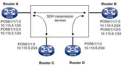
As shown in Figure 6,
· Router A and Router B provide 622 Mbps E-CPOS interfaces, while Router C and Router D provide 155 Mbps E-CPOS interfaces.
· Channelized interface POS 6/1/1/1:0 of Router A is connected to channelized interface POS 6/1/1/1:0 of Router B through an SDH transmission router.
· Channelized interface POS 6/1/1/2:0 of Router A is connected to interface POS 6/1/1:0 of Router C through an SDH transmission router.
· Channelized interface POS 6/1/1/2:0 of Router B is connected to interface POS 6/1/1:0 of Router D through an SDH transmission router.
· Each interface uses PPP on the data link layer; all routers use the clock of the SDH transmission router; the MTU of each interface is 9100 bytes.
Configuration procedure
1. Configure Router A:
# Configure the clock mode of interface E-CPOS 6/1/1.
<Sysname> system-view
[Sysname] controller E-Cpos 6/1/1
[Sysname-E-Cpos6/1/1] clock master
# Create two 155 Mbps POS interfaces on interface E-CPOS 6/1/1.
[Sysname-E-Cpos6/1/1] using oc-12
[Sysname-E-Cpos6/1/1] oc-3 1
[Sysname-E-Cpos6/1/1-oc-3-1] using oc-3c
[Sysname-E-Cpos6/1/1-oc-3-1] quit
[Sysname-E-Cpos6/1/1] oc-3 2
[Sysname-E-Cpos6/1/1-oc-3-2] using oc-3c
[Sysname-E-Cpos6/1/1-oc-3-2] quit
[Sysname-E-Cpos6/1/1] quit
# Configure channelized interface POS 6/1/1/1:0.
[Sysname] interface Pos6/1/1/1:0
[Sysname-Pos6/1/1/1:0] ip address 10.110.4.1 255.255.255.0
[Sysname-Pos6/1/1/1:0] mtu 9100
[Sysname-Pos6/1/1/1:0] quit
# Configure channelized interface POS 6/1/1/2:0.
[Sysname] interface Pos6/1/1/2:0
[Sysname-Pos6/1/1/2:0] ip address 10.110.5.1 255.255.255.0
[Sysname-Pos6/1/1/2:0] mtu 9100
[Sysname-Pos6/1/1/2:0] quit
2. Configure Router B:
# Configure the clock mode of interface E-CPOS 6/1/1.
<Sysname> system-view
[Sysname] controller E-Cpos 6/1/1
[Sysname-E-Cpos6/1/1] clock slave
# Create two 155 Mbps POS interfaces for E-CPOS 6/1/1.
[Sysname-E-Cpos6/1/1] oc-3 1
[Sysname-E-Cpos6/1/1-oc-3-1] using oc-3c
[Sysname-E-Cpos6/1/1-oc-3-1] quit
[Sysname-E-Cpos6/1/1] oc-3 2
[Sysname-E-Cpos6/1/1-oc-3-2] using oc-3c
[Sysname-E-Cpos6/1/1-oc-3-2] quit
[Sysname-E-Cpos6/1/1] quit
# Configure channelized interface POS 6/1/1/1:0.
[Sysname] interface Pos6/1/1/1:0
[Sysname-Pos6/1/1/1:0] ip address 10.110.4.2 255.255.255.0
[Sysname-Pos6/1/1/1:0] mtu 9100
[Sysname-Pos6/1/1/1:0] quit
# Configure channelized interface POS 6/1/1/2:0.
[Sysname] interface Pos6/1/1/2:0
[Sysname-Pos6/1/1/2:0] ip address 10.110.6.1 255.255.255.0
[Sysname-Pos6/1/1/2:0] mtu 9100
[Sysname-Pos6/1/1/2:0] quit
3. Configure Router C:
# Create a 155-Mbps POS channel on E-CPOS 6/1/1.
<Sysname> system-view
[Sysname] controller E-Cpos 6/1/1
[Sysname-E-Cpos6/1/1] using oc-3c
# Configure POS interface POS 6/1/1:0.
[Sysname]interface Pos6/1/1:0
[Sysname-Pos6/1/1:0] ip address 10.110.5.2 255.255.255.0
[Sysname-Pos6/1/1:0] mtu 9100
[Sysname-Pos6/1/1:0] quit
4. Configure Router D:
# Create a 155-Mbps POS channel on E-CPOS 6/1/1.
<Sysname> system-view
[Sysname] controller E-Cpos 6/1/1
[Sysname-E-Cpos6/1/1] using oc-3c
# Configure POS interface POS 6/1/1:0.
[Sysname] interface Pos6/1/1:0
[Sysname-Pos6/1/1:0] ip address 10.110.6.2 255.255.255.0
[Sysname-Pos6/1/1:0] mtu 9100
Use the display interface pos 6/1/1:0 command to check the connectivity status, and use the ping command to check whether the network is reachable.
Troubleshooting E-CPOS interfaces
Symptom
An E-CPOS interface is physically up, the channelized POS interfaces on it are up, but its link layer is down.
Solution
· The physical parameter settings (such as clock source and scrambling) on the E-CPOS interface do not match those on the remote E-CPOS interface.
· The link layer protocol of the POS channel does match that of the remote POS channel.
· The bandwidth of POS interfaces channelized from the local E-CPOS interface is not the same as that of POS interfaces channelized from the remote E-CPOS interface.
· POS interfaces channelized from the local E-CPOS interface are not the same as POS interfaces channelized from the remote E-CPOS interface in POS interface number.
· PPP authentication fails on the virtual POS interface. PPP authentication maybe fails due to incorrect PPP authentication parameters.
You can use the display interface pos interface-number command to display the multiplexing path and PPP link negotiation information of the specified POS interface.
An interface may be in one of the following four states:
· Posinterface-number current state: DOWN ( Administratively ). Line protocol current state: DOWN, indicating that the interface is administratively shut down.
· Posinterface-number current state: DOWN. Line protocol current state: DOWN, indicating that the interface is not enabled or has not gone up on the physical layer
· Posinterface-number current state: UP. Line protocol current state: UP, indicating that the interface has passed LCP negotiation.
· Posinterface-number current state: UP. Line protocol current state: DOWN, indicating that the interface has been activated but has not passed LCP negotiation.