- Table of Contents
- Related Documents
-
| Title | Size | Download |
|---|---|---|
| 01-Ethernet Interface Configuration | 181.32 KB |
Contents
Configuring Ethernet interfaces
Performing general configurations
Configuring the operating mode for a 10-GE interface
Configuring basic settings of an Ethernet interface or subinterface
Shutting down an Ethernet interface or subinterface
Configuring flow control on an Ethernet interface
Configuring physical state change suppression on an Ethernet interface
Configuring loopback testing on an Ethernet interface
Setting the interval for collecting Ethernet interface statistics
Configuring the link mode of an Ethernet interface
Configuring a Layer 2 Ethernet interface
Layer 2 Ethernet interface configuration task list
Setting speed options for auto negotiation on an Ethernet interface
Configuring storm suppression for an Ethernet interface
Enabling forwarding of jumbo frames
Configuring the MDI mode for an Ethernet interface
Configuring a Layer 3 Ethernet interface or subinterface
Layer 3 Ethernet interface or subinterface configuration task list
Setting the MTU for an Ethernet interface or subinterface
Enabling traffic statistics collection on an Ethernet subinterface
Displaying and maintaining an Ethernet interface or subinterface
|
|
NOTE: In this documentation, SPE cards refer to the cards prefixed with SPE, for example, SPE-1020-E-II. |
Ethernet interface overview
Ethernet is the most widespread wired LAN technology due to its flexibility, simplicity, and easy implementation. Your router supports the following types of Ethernet interfaces:
· Layer 2 Ethernet interfaces—They are physical interfaces operating on the data link layer for Layer 2 packet forwarding. They can only forward packets carrying source and destination IP addresses that belong to the same network segment.
· Layer 3 Ethernet interfaces—They are physical interfaces operating on the network layer for Layer 3 packet forwarding, and forward packets carrying source and destination IP addresses that belong to different network segments. You can assign an IP address to a Layer 3 Ethernet interface.
· Layer 2-Layer 3 Ethernet interfaces—They are physical interfaces that can operate on both the data link layer and the network layer. When operating on the data link layer, a Layer 2-Layer 3 Ethernet interface acts as a Layer 2 Ethernet interface. When operating on the network layer, a Layer 2-Layer 3 Ethernet interface acts as a Layer 3 Ethernet interface.
· Layer 3 Ethernet subinterfaces—They are logical interfaces operating on the network layer. You can assign an IP address to a Layer 3 Ethernet subinterface. By creating subinterfaces on a Layer 3 Ethernet interface, you can enable the interface to carry packets for multiple VLANs, which provides great networking flexibility.
· Virtual Ethernet interfaces—Including Layer 3 Virtual-Ethernet (VE) interfaces and Layer 2 VE (VE-bridge) interfaces. They are used on interface modules for carrying data link layer protocols over Ethernet.
Performing general configurations
This section describes the attributes and configurations common to Layer 2 and Layer 3 Ethernet interfaces/subinterfaces. For more information about the attributes and configuration, see “Configuring a Layer 2 Ethernet interface” and “Configuring a Layer 3 Ethernet interface or subinterface.”
Configuring a combo interface
Introduction to combo interfaces
A combo interface is a logical interface that comprises one optical (fiber) port and one electrical (copper) port. The two ports cannot work simultaneously. When you enable one port, the other is automatically disabled.
The fiber combo port and copper combo port share the same interface view, in which you can activate the fiber or copper combo port, and configure other port attributes such as the interface rate and duplex mode.
Configuration prerequisites
Before configuring a combo interface, identify which port of the interface is active with the display interface command:
· If the output includes “Media type is twisted pair, Port hardware type is 1000_BASE_T”, the copper combo port is active.
· If the output includes “Media type is not sure, Port hardware type is No connector”, the fiber combo port is active.
Changing the active port of a combo interface
To change the active port of a combo interface:
|
Step |
Command |
Remarks |
|
1. Enter system view. |
system-view |
N/A |
|
2. Enter Ethernet interface view. |
interface interface-type interface-number |
N/A |
|
3. Activate the fiber or copper combo port. |
combo enable { copper | fiber } |
Optional. By default, the copper combo port is active. |
|
|
CAUTION: After you activate the fiber combo port, the speed, duplex, and MDI settings will be automatically removed if the port does not support them. |
Configuring the operating mode for a 10-GE interface
Introduction to the operating modes
A ten-GigabitEthernet (10-GE) interface can operate in LAN or WAN mode.
· In LAN mode, the 10-GE interface transmits Ethernet packets, providing access to an Ethernet network.
· In WAN mode, the 10-GE interface transmits synchronous digital hierarchy (SDH) packets, providing access to an SDH network. In this mode, the interface supports only point-to-point connections.
|
|
CAUTION: A 10-GE interface in WAN mode encapsulates Ethernet packets as SDH frames, and a 10G packet over SDH (POS) interface encapsulates PPP packets as SDH frames. However, the two types of interfaces cannot communicate with each other, because the framing formats used by them are different. |
Introduction to J0 and J1 overhead bytes
SDH frames have diversified overhead bytes, which accomplish the operation and maintenance functions such as hierarchical management of the transport network. J0 and J1 are used to provide internetworking support between different countries, regions, or vendors.
The regenerator section trace byte J0 is usually set to a section access point identifier. The sending end keeps connected with the receiving end by sending this byte repeatedly.
The path trace byte J1, usually set to a high-order path access point identifier, functions in a similar way to keep connected with the receiving end of the path.
To ensure smooth communication, the J0 and J1 bytes should be matched respectively at the sending and receiving ends.
Configuration procedure
To configure a 10-GE interface to operate in LAN or WAN mode:
|
Step |
Command |
Remarks |
|
1. Enter system view. |
system-view |
N/A |
|
2. Enter ten-GigabitEthernet interface view. |
interface ten-gigabitethernet interface-number |
N/A |
|
3. Configure a 10-GE interface to operate in LAN or WAN mode. |
port-mode { lan | wan } |
Optional. By default, a 10-GE interface operates in LAN mode. |
|
4. Configure a value for J0 or J1 bytes when the 10-GE interface operates in WAN mode. |
flag { j0 | j1 } sdh value |
Optional. By default, the value of the J0 and J1 bytes is 0. |
|
|
NOTE: The flag command can only take effect on 10-GE interfaces operating in WAN mode. |
Configuring basic settings of an Ethernet interface or subinterface
Configuring an Ethernet interface
You can set an Ethernet interface to operate in one of the following duplex modes:
· Full-duplex mode (full)—Interfaces operating in this mode can send and receive packets simultaneously.
· Half-duplex mode (half)—Interfaces operating in this mode can either send or receive packets at a given time.
· Auto-negotiation mode (auto)—Interfaces operating in this mode determine their duplex mode through auto-negotiation.
Similarly, you can set the speed of an Ethernet interface or enable it to automatically negotiate a speed with its peer. For a 100-Mbps or 1000-Mbps Layer 2 Ethernet interface, you can also set speed options for auto negotiation. The two ends can pick a speed only from the available options. For more information, see “Setting speed options for auto negotiation on an Ethernet interface.”
To configure an Ethernet interface:
|
Step |
Command |
Remarks |
|
1. Enter system view. |
system-view |
N/A |
|
2. Enter Ethernet interface view. |
interface interface-type interface-number |
N/A |
|
3. Set the description. |
description text |
Optional. By default, the description of an interface is in the format of interface-name Interface. For example, M-Ethernet0/0/0 Interface. |
|
4. Set the duplex mode. |
duplex { auto | full | half } |
Optional. By default, the duplex mode is auto for Ethernet interfaces. Optical interfaces do not support the half keyword. 10-GE interfaces do not support this command. |
|
5. Set the transmission rate. |
speed { 10 | 100 | 1000 | auto } |
Optional. The default setting is auto. |
|
6. Restore the default settings. |
default |
Optional. |
|
|
NOTE: After you modify the rate or duplex mode of an interface, you must use the shutdown command to disable the interface and then use the undo shutdown command to enable it again, so as to start a new auto-negotiation process to make the new configuration take effect. |
Configuring an Ethernet subinterface
Layer 3 Ethernet subinterface enables Layer 3 Ethernet interfaces to identify packets by VLANs. By configuring multiple subinterfaces on an Ethernet interface, you can have packets of different VLANs forwarded through their corresponding subinterfaces, thus achieving flexibility.
To configure an Ethernet subinterface:
|
Step |
Command |
Remarks |
|
1. Enter system view. |
system-view |
N/A |
|
2. Create an Ethernet subinterface. |
interface interface-type interface-number.subnumber |
This command also leads you to Ethernet subinterface view. |
|
3. Set the interface description. |
description text |
Optional. By default, the description of an interface is in the format of interface-name Interface. For example, GigabitEthernet2/1/7.20 Interface. |
|
4. Restore the default settings. |
default |
Optional. |
|
|
NOTE: · You can configure IP addresses for Ethernet subinterfaces. For more information about IP addressing, see Layer 3—IP Services Configuration Guide. · For the local and remote Ethernet subinterfaces to transmit traffic correctly, configure them with the same subinterface number and VLAN ID. |
Shutting down an Ethernet interface or subinterface
You may need to shut down and then bring up an Ethernet interface or subinterface to activate some configuration changes, for example, the speed or duplex mode changes.
To shut down an Ethernet interface or subinterface:
|
Step |
Command |
Remarks |
|
1. Enter system view. |
system-view |
N/A |
|
2. Enter Ethernet interface or subinterface view, or port group view. |
·
Enter Ethernet interface view: ·
Enter port group view: · Enter Ethernet subinterface view: |
Use any command. To shut down an Ethernet interface or subinterface, enter Ethernet interface or subinterface view. To shut down all Ethernet interfaces in a port group, enter port group view. |
|
3. Shut down the Ethernet interface or subinterface. |
shutdown |
By default, Ethernet interfaces and subinterfaces are up. |
Configuring flow control on an Ethernet interface
You can avoid packet drops on a link by enabling flow control at both ends of the link. When traffic congestion occurs at the receiving end, the receiving end sends a flow control (Pause) frame to ask the sending end to suspend sending packets. In this way, flow control helps avoid packet drops.
To enable flow control on an Ethernet interface:
|
Step |
Command |
Remarks |
|
1. Enter system view. |
system-view |
N/A |
|
2. Enter Ethernet interface view. |
interface interface-type interface-number |
N/A |
|
3. Enable flow control. |
flow-control |
By default, flow control is disabled. |
Configuring physical state change suppression on an Ethernet interface
The physical link state of an Ethernet interface is either up or down. Each time the physical link of a port goes up or comes down, the physical layer reports the change to the upper layers, and the upper layers handle the change, resulting in increased overhead.
To prevent physical link flapping from affecting system performance, configure physical state change suppression to delay the reporting of physical link state changes. The physical layer reports the changes only when the delay expires.
To configure physical state change suppression on an Ethernet interface:
|
Step |
Command |
Remarks |
|
1. Enter system view. |
system-view |
N/A |
|
2. Enter Ethernet interface view. |
interface interface-type interface-number |
N/A |
|
3. Set the physical state change suppression interval. |
link-delay delay-time |
The default setting is one second. |
Configuring loopback testing on an Ethernet interface
If an Ethernet interface does not work normally, you can enable loopback testing on it to identify the problem. Loopback testing has the following types:
· Internal loopback testing—Packets sent from the interface are internally looped back to the interface without being sent onto the line. If the internal operation of the interface is normal, the interface should be able to receive the self-sent packets.
· External loopback testing—To perform external loopback testing on an Ethernet interface, connect a loopback plug to the Ethernet interface. The device sends test packets out the interface, which are expected to loop over the plug and back to the interface. If the interface fails to receive any test packet, the hardware of the interface is faulty.
An Ethernet interface in a loopback test does not forward data traffic.
To enable loopback testing on an Ethernet interface:
|
Step |
Command |
Remarks |
|
1. Enter system view. |
system-view |
N/A |
|
2. Enter Ethernet interface view. |
interface interface-type interface-number |
N/A |
|
3. Enable loopback testing. |
loopback { external | internal } |
Optional. By default, loopback test is disabled. |
|
|
NOTE: · The router does not support the loopback external command. · As for internal loopback testing and external loopback testing, if an interface is down, only the former is available on it; if the interface is shut down, both are unavailable. · The speed, duplex, mdi, combo enable, and shutdown commands are not applicable during loopback test. · With loopback test enabled, the Ethernet interface operates in full duplex mode. With loopback test disabled, the original configurations will be restored. · After configuring the loopback internal command and then the undo loopback command on an Ethernet interface, you should re-enable the interface with the shutdown command and then the undo shutdown command to trigger an auto-negotiation on the interface. |
Setting the interval for collecting Ethernet interface statistics
To configure the interval for collecting interface statistics:
|
Step |
Command |
Remarks |
|
1. Enter system view. |
system-view |
N/A |
|
2. Configure the interval for collecting interface statistics. |
flow-interval interval |
Optional The default setting is 300 seconds. |
Configuring the link mode of an Ethernet interface
Depending on the layer (data link layer or network layer) at which the device processes the packets received on an interface, an interface can be as a Layer 2 Ethernet interface (in bridge mode) or as a Layer 3 Ethernet interface (in route mode). You can configure an Ethernet interface as a Layer 2 Ethernet interface or Layer 3 Ethernet interface by setting the link mode to bridge or route.
To change the link mode of an Ethernet interface:
|
Step |
Command |
Remarks |
|
1. Enter system view. |
system-view |
N/A |
|
2. Change the link mode of Ethernet interfaces. |
·
(Approach I) In
system view: · (Approach II) In Ethernet interface view: a. interface interface-type interface-number b. port link-mode { bridge | route } |
Use either approach. By default, Ethernet interfaces work in route mode. |
|
|
CAUTION: · After you change the link mode of an Ethernet interface, all the settings of the Ethernet interface are restored to their defaults under the new link mode. · The link mode configuration for an Ethernet interface in system view and in interface view supersedes each other. |
Configuring a Layer 2 Ethernet interface
Layer 2 Ethernet interface configuration task list
Complete these tasks to configure an Ethernet interface operating in bridge mode:
|
Task |
Remarks |
|
Optional |
|
|
Setting speed options for auto negotiation on an Ethernet interface |
Optional Applicable to 100-Mbps or 1000-Mbps Layer 2 Ethernet interfaces |
|
Optional |
|
|
Optional |
|
|
Optional |
Configuring a port group
The SR8800 routers allow you to configure some functions on multiple interfaces at a time. For example, you can configure a traffic suppression threshold (see “Setting speed options for auto negotiation on an Ethernet interface”) for multiple interfaces in bulk by assigning these interfaces to a port group.
A port group is created manually and the settings you made on it apply to all group member interfaces. Note that even though the settings are made on the port group, they are saved on an interface basis rather than on a port group basis. Thus, you can only view the settings in the view of each interface with the display current-configuration command or the display this command.
To configure a manual port group:
|
Step |
Command |
|
1. Enter system view. |
system-view |
|
2. Create a manual port group and enter manual port group view. |
port-group manual port-group-name |
|
3. Add Ethernet interfaces to the manual port group. |
group-member interface-list |
Setting speed options for auto negotiation on an Ethernet interface
Speed auto negotiation enables an Ethernet interface to negotiate with its peer for the highest speed supported by both ends by default. You can narrow down the speed option list for negotiation.
Figure 1 Speed auto negotiation application scenario
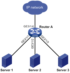
As shown in Figure 1, all ports on Router A are operating in speed auto negotiation mode, with the highest speed of 1000 Mbps. If the transmission rate of each server in the server cluster is 1000 Mbps, their total transmission rate will exceed the capability of port GigabitEthernet 3/1/4, the port providing access to the Internet for the servers.
To avoid congestion on GigabitEthernet 3/1/4, set 100 Mbps as the only option available for speed negotiation on port GigabitEthernet 3/1/1, GigabitEthernet 3/1/2, and GigabitEthernet 3/1/3. As a result, the transmission rate on each port connected to a server is limited to 100 Mbps.
To set speed options for auto negotiation on an Ethernet interface:
|
Step |
Command |
Remarks |
|
1. Enter system view. |
system-view |
N/A |
|
2. Enter Ethernet interface view. |
interface interface-type interface-number |
N/A |
|
3. Set speed options for auto negotiation. |
speed auto [ 10 | 100 | 1000 ] * |
Optional. By default, the options for auto negotiation are not restricted. |
|
|
NOTE: · Support for this feature varies with interface cards or subcards. · The speed and speed auto commands supersede each other, and whichever is configured last takes effect. |
Configuring storm suppression for an Ethernet interface
You can use the storm suppression function to limit the size of a particular type of traffic (broadcast, multicast, or unknown unicast traffic).
You can set the upper limit of broadcast, multicast, or unknown unicast traffic allowed to pass through the system as a whole. When the sum of broadcast, multicast, or unknown unicast traffic arriving on all interfaces of the system exceeds this threshold, the system discards packets until the traffic drops below this threshold.
To set storm suppression thresholds on one or multiple Ethernet interfaces:
|
Step |
Command |
Remarks |
|
1. Enter system view. |
system-view |
N/A |
|
2. Enter Ethernet interface view or port group view. |
·
Enter Ethernet interface view: ·
Enter port group view: |
Use either command. To configure storm suppression on an Ethernet interface, enter Ethernet interface view. To configure storm suppression on a group of Ethernet interfaces, enter port group view. |
|
3. Configure broadcast storm suppression. |
broadcast-suppression { ratio | pps max-pps | kbps max-kbps } |
Optional. By default, broadcast traffic is not suppressed. SPE cards support only the ratio argument. |
|
4. Set the multicast suppression threshold ratio. |
multicast-suppression { ratio | pps max-pps | kbps max-kbps } |
Optional. By default, multicast traffic is not suppressed. SPE cards do not support the command. |
|
5. Set the unknown unicast suppression threshold ratio. |
unicast-suppression { ratio | pps max-pps | kbps max-kbps } |
Optional. By default, unknown unicast traffic is not suppressed. SPE cards do not support the command. |
|
|
NOTE: If you set storm suppression ratios in Ethernet interface view or port group view repeatedly for an Ethernet interface that belongs to a port group, only the latest settings take effect. |
Enabling forwarding of jumbo frames
Due to tremendous amount of traffic occurring in Ethernet, it is likely that some frames might have a frame size greater than the standard Ethernet frame size. If you have not configured the system to allow such frames (called jumbo frames) to pass through Ethernet interfaces, the system will drop these frames. After you enable this function in the system, the system processes jumbo frames that are within the length range you specified.
To enable forwarding of jumbo frames:
|
Step |
Command |
Remarks |
|
1. Enter system view. |
system-view |
N/A |
|
2. Enable forwarding of jumbo frames. |
jumboframe enable [ value ] slot slot-num |
By default, the router allows 9216-byte jumbo frames to pass through Ethernet interfaces. |
Configuring the MDI mode for an Ethernet interface
|
|
NOTE: Optical ports do not support this function. |
Two types of Ethernet cables can be used to connect Ethernet devices: crossover cable and straight-through cable. To accommodate these two types of cables, an Ethernet interface on the router may operate in one of the following three Medium Dependent Interface (MDI) modes:
· Across mode
· Normal mode
· Auto mode
An Ethernet interface is composed of eight pins. By default, each pin has its particular role. For example, pin 1 and pin 2 transmit signals; pin 3 and pin 6 receive signals. You can change the pin roles by setting the MDI mode. For an Ethernet interface in normal mode, the pin roles are not changed. For an Ethernet interface in across mode, pin 1 and pin 2 are used for receiving signals; pin 3 and pin 6 are used for transmitting signals. To ensure normal communication, you must connect the local transmit pins to the remote receive pins. Therefore, you should configure the MDI mode depending on cable type.
· Normally, the auto mode is used. The other two modes are useful only when the router cannot determine the cable type.
· When straight-through cables are used, the local MDI mode must be different from the remote MDI mode.
· When crossover cables are used, the local MDI mode must be the same as the remote MDI mode, or the MDI mode of at least one end must be set to auto.
To configure the MDI mode for an Ethernet interface:
|
Step |
Command |
Remarks |
|
1. Enter system view. |
system-view |
N/A |
|
2. Enter Ethernet interface view. |
interface interface-type interface-number |
N/A |
|
3. Configure the MDI mode for the Ethernet interface. |
mdi { across | auto | normal } |
Optional. The default setting is auto. That is, the Ethernet interface determines the physical pin roles (transmit or receive) through negotiation. |
Configuring a Layer 3 Ethernet interface or subinterface
Layer 3 Ethernet interface or subinterface configuration task list
Complete the following task to configure a Layer 3 Ethernet interface or subinterface:
|
Task |
Remarks |
|
Optional Applicable to Layer 3 Ethernet interfaces and subinterfaces |
|
|
Enabling traffic statistics collection on an Ethernet subinterface |
Optional Applicable to Layer 3 Ethernet subinterfaces |
Setting the MTU for an Ethernet interface or subinterface
The value of maximum transmission unit (MTU) affects the fragmentation and re-assembly of IP packets.
To set the MTU for an Ethernet interface or subinterface:
|
Step |
Command |
Remarks |
|
1. Enter system view. |
system-view |
N/A |
|
2. Enter Ethernet interface or subinterface view. |
interface interface-type { interface-number | interface-number.subnumber } |
N/A |
|
3. Set the MTU. |
mtu size |
The default setting is 1500 bytes. |
Enabling traffic statistics collection on an Ethernet subinterface
This feature enables you to monitor traffic by providing the statistics about the inbound and outbound unicast packets, multicasts, and broadcasts of a subinterface.
To enable traffic statistics collection on an Ethernet subinterface:
|
Step |
Command |
Remarks |
|
1. Enter system view. |
system-view |
N/A |
|
2. Enter Ethernet subinterface view. |
interface interface-type interface-number.subnumber |
N/A |
|
3. Enable traffic statistics collection on the Ethernet subinterface. |
By default, traffic statistics collection is disabled on an Ethernet subinterface. |
|
|
CAUTION: · To view the traffic statistics on Ethernet subinterfaces, use the display interface command. · Do not simultaneously enable traffic statistics collection and ACL functions (such as packet filtering and Portal) that may conflict with the traffic statistics collection. · This feature is available only on SPE cards. |
Configuring a VE interface
Introduction
Virtual Ethernet (VE) interfaces are logical interfaces implemented on interface cards. They fall into Layer 3 VE interfaces and Layer 2 VE-bridge interfaces. The VE interfaces are mainly used for IPoEoA and EoA.
IPoEoA and EoA carry Ethernet packets over ATM by binding VE interfaces to permanent virtual channels (PVCs). IPoEoA is for Layer 3 VE interface binding, and EoA is for Layer 2 VE interface binding. For more information, see Layer 2—WAN Configuration Guide.
Configuration procedure
When implementing IPoEoA and EoA through a PVC, you must associate the PVC with a VE interface. Otherwise, you cannot configure the PVC.
Configuring a Layer 3 VE interface
To configure a Layer 3 VE Interface:
|
Step |
Command |
Remarks |
|
1. Enter system view. |
system-view |
N/A |
|
2. Create a Layer 3 VE interface and enter Layer 3 VE interface view. |
interface virtual-ethernet interface-number |
If the specified Layer 3 VE interface already exists, you enter Layer 3 VE interface view directly. You can create up to 1024 Layer 3 VE interfaces. |
|
3. Change the MAC address of the Layer 3 VE interface. |
mac-address mac-address |
Optional. After configuring this command, run the reset arp command to make the new MAC address take effect. For more information about the reset arp command, see Layer 3—IP Services Command Reference. |
Configuring a Layer 2 VE interface
To configure a Layer 2 VE Interface:
|
Step |
Command |
Remarks |
|
1. Enter system view. |
system-view |
N/A |
|
2. Create a Layer 2 VE interface and enter Layer 2 VE interface view. |
interface ve-bridge interface-number |
If the specified Layer 2 VE interface already exists, you enter Layer 2 VE interface view directly. You can create up to 1024 Layer 2 VE interfaces. |
|
|
NOTE: · Due to the restriction of hardware resources, each VLAN can contain a maximum number of 64 Layer 2 VE interfaces on each card. · For more information about the IPoEoA and EoA configuration, see Layer 2—WAN Configuration Guide. |
Displaying and maintaining an Ethernet interface or subinterface
|
Task |
Command |
Remarks |
|
Display Ethernet interface or subinterface information. |
display interface [ interface-type ] brief [ down ] [ | { begin | exclude | include } regular-expression ] display interface interface-type { interface-number | interface-number.subnumber } [ brief ] [ | { begin | exclude | include } regular-expression ] |
Available in any view |
|
Display traffic statistics for the specified interfaces. |
display counters { inbound | outbound } interface [ interface-type ] [ | { begin | exclude | include } regular-expression ] |
Available in any view |
|
Display traffic rate statistics over the last sampling interval. |
display counters rate { inbound | outbound } interface [ interface-type ] [ | { begin | exclude | include } regular-expression ] |
Available in any view |
|
Display the information about a manual port group or all manual port groups. |
display port-group manual [ all | name port-group-name ] [ | { begin | exclude | include } regular-expression ] |
Available in any view |
|
Display Layer 2 VE interface information. |
display interface [ ve-bridge ] [ brief [ down ] ] [ | { begin | exclude | include } regular-expression ] display interface ve-bridge interface-number [ brief ] [ | { begin | exclude | include } regular-expression ] |
Available in any view |
|
Display Layer 3 VE interface information. |
display interface [ virtual-ethernet ] [ brief [ down ] ] [ | { begin | exclude | include } regular-expression ] display interface virtual-ethernet { interface-number | interface-number.subnumber } [ brief ] [ | { begin | exclude | include } regular-expression ] |
Available in any view |
|
Clear the interface or subinterface statistics. |
reset counters interface [ interface-type [ interface-number | interface-number.subnumber ] ] |
Available in user view |
|
Clear the Layer 2 VE interface statistics. |
reset counters interface [ ve-bridge [ interface-number ] ] |
Available in user view |
|
Clear the Layer 3 VE interface statistics. |
reset counters interface [ virtual-ethernet [ interface-number ] ] |
Available in user view |