- Table of Contents
- Related Documents
-
| Title | Size | Download |
|---|---|---|
| 04-CPOS Interface Configuration | 225.76 KB |
Contents
Multiplexing E1/T1/E3/T3 channels to form STM-1
Calculating E1/T1/E3/T3 channel sequence numbers
CPOS interface application scenario
Displaying and maintaining CPOS interfaces
CPOS interface configuration example
Troubleshooting CPOS interfaces
Interface physical status is up, link protocol status is down, and loopback is detected
|
|
NOTE: Only the PIC-CLF2G8L and PIC-CLF4G8L sub-cards have channelized E3/T3 interfaces. |
Overview
SONET
Synchronous Optical Network (SONET), a synchronous transmission system defined by the ANSI, is an international standard transmission protocol. It adopts optical transmission.
SDH
Synchronous Digital Hierarchy (SDH), defined by the CCITT (today’s ITU-T), uses a SONET rate subset. As SDH uses synchronous multiplexing and a flexible mapping structure, low-speed tributary signals can be added to or dropped from an SDH signal without a large amount of multiplexing/demultiplexing devices. This reduces signal attenuation and investment in network devices.
CPOS
The Low-speed tributary signals multiplexed to form an SDH signal are called channels. The channelized POS (CPOS) interface makes full use of SDH to provide precise bandwidth division, reduce the number of low-speed physical interfaces on network devices, enhance their aggregation capacity, and improve the access capacity of leased lines.
The CPOS interface operates at the rate of STM-1.
SDH frame structure
To understand the benefits of CPOS, you need to first understand the frame structure of SDH signal STM-N.
Low-speed tributary signals should distribute in one frame regularly and evenly for the convenience of adding them to or dropping them from high-speed signals. The ITU-T specifies that STM-N frames adopt the structure of rectangle blocks in bytes, as illustrated in Figure 1:
Figure 1 STM-N frame structure
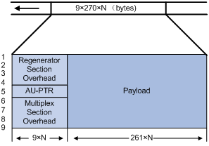
STM-N is a rectangle-block frame structure of 9 rows x 270 x N columns, where the N in STM-N equals the N columns. N takes the value 1, 4, 16, and so on, indicating the number of STM-1 signals that form SDH signal.
The STM-N frame structure consists of three parts: the section overhead (SOH), which includes the regenerator section overhead (RSOH) and the multiplex section overhead (MSOH); the administration unit pointer (AU-PTR); and payload. AU-PTR is the pointer that indicates the location of the first byte of the payload in an STM-N frame so that the receiving end can correctly extract the payload.
Terms
· Multiplex unit—A basic SDH multiplex unit includes multiple containers (C-n), virtual containers (VC-n), tributary units (TU-n), tributary unit groups (TUG-n), administrative units (AU-n) and administrative unit groups (AUG-n), where n is the hierarchical sequence number of unit level.
· Container—Information structure unit that carries service signals at different rates. G.709 defines the criteria for five standard containers: C-11, C-12, C-2, C-3 and C-4.
· Virtual container (VC)—Information structure unit supporting channel layer connection of SDH. It terminates an SDH channel. VC is divided into lower-order and higher-order VCs. VC-4 and VC-3 in AU-3 are higher-order virtual containers.
· Tributary unit (TU) and tributary unit group (TUG)—TU is the information structure that provides adaptation between higher-order and lower-order channel layers. TUG is a set of one or more TUs whose location is fixed in higher-order VC payload.
· Administrative unit (AU) and administrative unit group (AUG)—AU is the information structure that provides adaptation between higher-order channel layer and multiplex section layer. AUG is a set of one or more AUs whose locations are fixed in the payload of STM-N.
Multiplexing E1/T1/E3/T3 channels to form STM-1
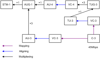
In the SDH multiplexing recommended by G.709, more than one path is available for a valid payload to be multiplexed to form STM-N. The following figures illustrate the multiplexing processes from E1, T1, E3, and T3 to STM-1.
Figure 2 Process of multiplexing E1 channels to form STM-1
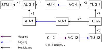
Figure 3 Process of multiplexing T1 channels to form STM-1
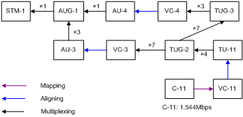
Figure 4 Process of multiplexing E3 channels to form STM-1
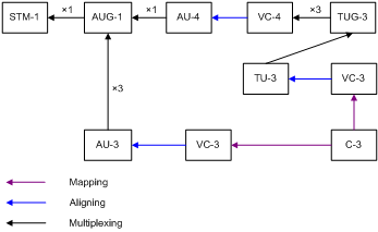
Figure 5 Process of multiplexing T3 channels to form STM-1
In actual applications, different countries and regions may adopt different multiplexing structures. To ensure interoperability, the multiplex mode command is provided on CPOS interfaces. This allows you to select the AU-3 or AU-4 multiplexing structure.
Calculating E1/T1/E3/T3 channel sequence numbers
Since CPOS interfaces adopt the byte interleaved multiplexing mode, the lower-order VCs are not arranged in sequential order in a higher-order VC. To understand how TU numbers are calculated, see the following example where E1 channels are multiplexed to form STM-1 through the AU-4.
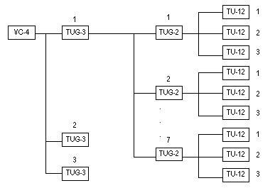
As shown in Figure 2, when the AU-4 path is used, the multiplexing structure for 2 Mbps is 3-7-3. The formula for calculating the TU-12 sequence numbers of different locations in the same VC-4 is as follows:
Sequence number of TU-12 = TUG-3 number + (TUG-2 number – 1) x 3 + (TU-12 Number – 1) x 21
The two TU-12s are adjacent to each other, if they have the same TUG-3 number and TUG-2 number but different TU-12 numbers with a discrepancy of 1.
|
|
NOTE: The numbers in the aforementioned formula refer to the location numbers in a VC-4 frame. TUG-3 can be numbered in the range of 1 to 3; TUG-2 in the range of 1 to 7 and TU-12 in the range of 1 to 3. TU-12 numbers indicate the order in which the 63 TU-12s in a VC-4 frame are multiplexed, that is, E1 channel numbers. |
Figure 6 Order of TUG-3s, TUG-2s, and TU-12s in a VC-4 frame
You can calculate TU-12 numbers in the same way when the AU-3 path is used.
When 63 E1 channels or 84 T1 channels are configured on a CPOS interface, you can reference E1 or T1 channels by referencing the numbers in the range of 1 to 63 or 1 to 84. When connecting your router to channelized STM-1 interfaces on routers of other vendors, you should consider the possible numbering differences due to different channel referencing approaches.
Figure 7 Order of TUG-3, VC-3, and C-3 in a VC-4 frame
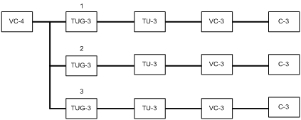
The channel number calculation for E3/T3 channels is simpler than that for E1/T1 channels. As shown in Figure 7, when the AU-4 multiplexing path is used, as TUG-3 and VC-3 are not divided into lower-order paths, the E3/T3 channel numbers are the TUG-3 numbers. When the AU-3 multiplexing path is used, you can get the E3/T3 channel numbers in the same way.
Overhead bytes
SDH provides layered monitoring and management of precise division.
It provides monitoring at section and channel levels, where sections are subdivided into regenerator and multiplex sections, and channels are subdivided into higher-order and lower-order paths. These monitoring functions are implemented using overhead bytes.
|
|
NOTE: SDH provides a variety of overhead bytes, but only those involved in CPOS configuration are discussed in this section. |
· SOH
Section overhead (SOH) consists of regenerator section overhead (RSOH) and multiplex section overhead (MSOH).
The regeneration section trace message J0 is included in RSOH to send the section access point identifier repeatedly. Based on the identifier, the receiver can make sure that it is in continuous connection with the sender. This byte can be any character in the network of the same operator. If the networks of two operators are involved, the sending and receiving devices at network borders must use the same J0 byte. With the j0 byte, operators can detect and troubleshoot faults in advance or use less time to recover networks.
· POH
The payload of an STM-N frame includes path overhead (POH), which monitors low-speed tributary signals.
While the SOH monitors the section layer, the POH monitors the path layer. The POH is divided into the higher-order path overhead and the lower-order path overhead.
Higher-order path overhead monitors paths at the VC-4/VC-3 level.
Similar to the J0 byte, the higher-order VC-N path trace byte J1 is included in the higher-order path overhead to send the higher-order path access point identifier repeatedly. Based on the identifier, the receiving end of the path can make sure that it is in continuous connection with the specified sending end. The J1 byte at the receiving and transmission ends should be matched.
In addition, the path signal label byte C2 is also included in the higher-order path overhead to indicate the multiplexing structure of VC frames and the property of payload, for instance, whether the path is carrying services, what type of services are carried, and how they are mapped. The sender and receiver must use the same C2 byte.
CPOS interface application scenario
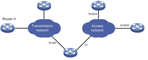
CPOS is used to enhance the capability of a router in low-speed access aggregation. STM-1 CPOS is especially suitable for aggregating E1/T1 channels.
At present, some government agencies and enterprises use low-end and mid-range network devices to access transmission networks through E1/T1 leased lines. Users who require bandwidth between E1 (2 Mbps)/T1 (1.5 Mbps) and E3 (34 Mbps)/T3 (44 Mbps), a data center for example, lease multiple E1/T1 lines.
The bandwidth of all these users is aggregated to one or more CPOS interfaces through a transmission network, and then connected to a high-end router where the low-end routers are uniquely identified by timeslots.
In actual applications, the connection between these low-end routers and the CPOS interfaces may span more than one transmission network and as such, may require relay. This is similar to the scenario where low-end devices are connected to a high-end device through one or multiple E1/T1 leased lines. Figure 8 shows such an application scenario.
Configuring a CPOS interface
To configure a CPOS interface:
|
Step |
Command |
Remarks |
|
1. Enter system view. |
system-view |
N/A |
|
2. Enter CPOS interface view. |
controller cpos cpos-number |
N/A |
|
3. Set the interface description. |
description text |
By default, the description of a CPOS interface is interface name Interface, for example, Cpos2/1/9 Interface. |
|
4. Set the framing format. |
frame-format { sdh | sonet } |
Optional. SDH by default. |
|
5. Set the clock mode. |
clock { master | slave } |
Optional. Slave by default. |
|
6. Set the loopback mode. |
loopback { local | remote } |
Optional. Disabled by default. |
|
7. Configure the AUG multiplexing mode. |
multiplex mode { au-3 | au-4 } |
Optional. The default is au-3 for SONET and au-4 for SDH. |
|
8. Configure the SOH and higher-order path overhead bytes. |
· flag { c2 path-number c2-value | s1 s1-value | s1s0 path-number s1s0-value } · flag { j0 | j1 path-number } { sdh | sonet } flag-value |
Optional. · The default value of c2 is 0x02 (hexadecimal) and s1 is 0x0f (hexadecimal). The default value of s1s0 is 0x0 for SONET and 0x2 for SDH. · For SONET frames, the default value of j0 is 0x01 and that of j1 is null; for SDH frames, the initial values (for example, the value when the router is initially powered on) of both j0 and j1 are SR8800, and the values change to null after a change in the framing format. |
|
9. Restore the default settings. |
default |
Optional. |
|
10. Shut down the CPOS interface. |
shutdown |
Optional. By default, a CPOS interface is up. |
|
11. Bring up the CPOS interface. |
undo shutdown |
Optional. By default, a CPOS interface is up. |
|
12. Configure the signal degrade (SD) threshold and the signal fail (SF) threshold. |
threshold { sd | sf } value |
Optional. By default, the SD alarm threshold is 10e-6; the SF alarm threshold is 10e-4 for PIC-CLF2G8L and PIC-CLF4G8L CPOS sub-cards and 10e-3 for other types of CPOS sub-cards. |
|
13. Configure E1/T1/E3/T3 channel attributes. |
· See “Configuring an E1 channel.” · See “Configuring a T1 channel.” · See “Configuring an E3 channel.” · See “Configuring a T3 channel.” |
Optional. |
|
|
NOTE: · E1 configuration is supported on the CPOS(E) interface module but T1 configuration is supported on the CPOS (T) interface module. · If no cable is connected to a physical interface, shut down the interface with the shutdown command to prevent anomalies caused by interference. · Use the shutdown command with caution, because once an interface is shut down, it stops operating. |
Configuring an E1 channel
To configure an E1 channel:
|
Step |
Command |
Remarks |
|
1. Enter system view. |
system-view |
N/A |
|
2. Enter CPOS interface view. |
controller cpos cpos-number |
N/A |
|
3. Set the framing format for an E1 channel. |
e1 e1-number set frame-format { crc4 | no-crc4 } |
Optional. The default is no-CRC4. An E1 channel working in unframed mode does not support framing format setting. |
|
4. Set the clock mode for an E1 channel. |
e1 e1-number set clock { master | slave } |
Optional. The default is slave. |
|
5. Set the loopback mode for an E1 channel. |
e1 e1-number set loopback { local | payload | remote } |
Optional. Disabled by default. |
|
6. Set the overhead bytes for an E1 channel. |
e1 e1-number set flag c2 c2-value e1 e1-number set flag j2 { sdh | sonet } j2-string |
Optional. The default value of C2 is 0x02 (in hexadecimal). The initial value (for example, the value when the router is initially powered on) of J2 is “SR8800”, but it changes to null (the default value) after a change in the framing format. |
|
7. Configure the operating mode for an E1 channel. |
·
Configure an E1 channel to operate in unframed
mode: · Configure an E1 channel to operate in framed mode and perform timeslot bundling to generate a serial interface a. (Optional) undo e1 e1-number unframed b. e1 e1-number channel-set set-number timeslot-list range |
Use either approach. By default, the E1 channel operates in framed mode. |
|
8. Shut down an E1 channel. |
e1 e1-number shutdown |
Optional. By default, an E1 channel is up. |
Configuring a T1 channel
To configure a T1 channel:
|
Step |
Command |
Remarks |
|
9. Enter system view. |
system-view |
N/A |
|
10. Enter CPOS interface view. |
controller cpos cpos-number |
N/A |
|
11. Set the framing format for a T1 channel. |
t1 t1-number set frame-format { esf | sf } |
Optional. The default is ESF. A T1 channel working in unframed mode does not support framing format setting. |
|
12. Set the clock mode for a T1 channel. |
t1 t1-number set clock { master | slave } |
Optional. The default is slave. |
|
13. Set the loopback mode for a T1 channel. |
t1 t1-number set loopback { local | payload | remote } |
Optional. Disabled by default. |
|
14. Set the overhead bytes for a T1 channel. |
· t1 t1-number set flag c2 c2-value · t1 t1-number set flag j2 { sdh | sonet } j2-string |
Optional. The default value of C2 is 0x02. The initial value (for example, the value when the router is initially powered on) of J2 is “SR8800” and the value changes to null (the default value) after a change in the framing format. |
|
15. Configure the operating mode for a T1 channel. |
·
Approach I: ·
Approach II: a. (Optional) undo t1 t1-number unframed b. t1 t1-number channel-set set-number timeslot-list range [ speed { 56k | 64k } ] |
Use either approach. By default, the T1 channel operates in framed mode. |
|
16. Shut down a T1 channel. |
t1 t1-number shutdown |
Optional. By default, a T1 channel is up. |
Configuring an E3 channel
To configure an E3 channel:
|
Step |
Command |
Remarks |
|
1. Enter system view. |
system-view |
N/A |
|
2. Enter CPOS interface view. |
controller cpos cpos-number |
N/A |
|
3. Create a serial interface corresponding to the unframed E3 channel. |
using e3 e3-number |
Optional. By default, no serial interface is created. |
|
4. Configure a serial port corresponding to the framed E3 channel. |
e3 e3-number framed |
Optional. By default, no serial port is configured. |
|
5. Configure the clock mode of the E3 channel. |
e3 e3-number set clock { master | slave } |
Optional. Slave by default. |
|
6. Enable loopback in the specified mode on the E3 channel. |
e3 e3-number set loopback { local | payload | remote } |
Optional. Disabled by default. |
|
7. Set the national bit of the E3 channel. |
e3 e3-number set national-bit { 0 | 1 } |
Optional. 1 by default. This command is unavailable when an E3 channel works in unframed mode. |
|
8. Shut down the E3 channel. |
e3 e3-number shutdown |
Optional. Up by default. |
|
|
NOTE: The router does not support adding a serial interface corresponding to the E3 channel to the specified MP-group. |
Configuring a T3 channel
|
Step |
Command |
|
|
system-view |
N/A |
|
|
2. Enter CPOS interface view. |
controller cpos cpos-number |
|
|
3. Create a serial interface corresponding to the unframed T3 channel. |
using t3 t3-number |
Optional. By default, no serial interface is created. |
|
4. Configure a serial port corresponding to the framed T3 channel. |
t3 t3-number framed |
Optional. By default, no serial port is configured. |
|
5. Configure the clock mode of the T3 channel. |
t3 t3-number set clock { master | slave } |
Optional. Slave by default |
|
6. Set the framing format of the T3 interface. |
t3 t3-number set frame-format { c-bit | m23 } |
Optional. C-bit framing by default A T3 channel working in unframed mode does not support framing format setting. |
|
7. Enable loopback in the specified mode on the T3 channel. |
t3 t3-number set loopback { local | payload | remote } |
Optional. Disabled by default. |
|
|
NOTE: The router does not support adding a serial interface corresponding to the T3 channel to the specified MP-group. |
Displaying and maintaining CPOS interfaces
|
Command |
Remarks |
|
|
Display information about channels on a specified or all CPOS interfaces. |
display controller cpos [ cpos-number ] [ | { begin | exclude | include } regular-expression ] |
Available in any view |
|
Display information about a specified E1 channel on a CPOS interface. |
display controller cpos cpos-number e1 e1-number [ | { begin | exclude | include } regular-expression ] |
Available in any view |
|
Display information about a specified T1 channel on a CPOS interface. |
display controller cpos cpos-number t1 t1-number [ | { begin | exclude | include } regular-expression ] |
Available in any view |
|
Display information about a specified E3 channel on a CPOS interface. |
display controller cpos cpos-number e3 e3-number [ | { begin | exclude | include } regular-expression ] |
Available in any view |
|
Display information about a specified T3 channel on a CPOS interface. |
display controller cpos cpos-number t3 t3-number [ | { begin | exclude | include } regular-expression ] |
Available in any view |
|
Display information about an E1/T1/E3/T3 serial interface. |
display interface serial [ interface-number:set-number ] [ | { begin | exclude | include } regular-expression ] |
Available in any view |
|
Clear the controller counter of a CPOS interface. |
reset counters controller cpos interface-number |
Available in user view |
|
|
NOTE: For more information about the display interface and display interface serial commands, see Interface Command Reference. |
CPOS interface configuration example
Network requirements
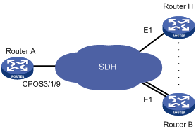
As shown in Figure 9, branch nodes Router B through Router H are uplinked to the central node Router A through E1 links and Router A aggregates these E1 links with a CPOS interface.
Add one more E1 link on Router B to expand its capacity. In addition, bind the two E1 links through an MP-group interface.
Configuration procedure
|
|
NOTE: · Because the clock source of a SONET/SDH network is more precise than the internal clock source of the router, when connecting the router to a SONET/SDH router, configure the clock mode of the SONET/SDH router as master. · This section describes only the important steps in configuring CPOS and E1 interfaces. Other configurations are not shown. |
1. Configure Router A:
# Configure the E1 channels of CPOS interface CPOS 3/1/9 to operate in unframed mode.
<Sysname> system-view
[Sysname] controller Cpos 3/1/9
[Sysname-Cpos3/1/9] e1 1 unframed
[Sysname-Cpos3/1/9] e1 2 unframed
# Create MP-group interface 3/1/28 and assign an IP address for it.
[Sysname] interface Mp-group 3/1/28
[Sysname-Mp-group3/1/28] ip address 10.1.1.1 24
[Sysname-Mp-group3/1/28] quit
# Configure interfaces Serial 3/1/9/1:0 and Serial 3/1/9/2:0.
[Sysname] interface Serial3/1/9/1:0
[Sysname-Serial3/1/9/1:0] ppp mp Mp-group 3/1/28
[Sysname-Serial3/1/9/1:0] quit
[Sysname] interface Serial3/1/9/2:0
[Sysname-Serial3/1/9/2:0] ppp mp Mp-group 3/1/28
[Sysname-Serial3/1/9/2:0] quit
2. Configure Router B:
The configuration on Router B is similar to that on other branch nodes.
<Sysname> system-view
[Sysname] controller E1 3/1/9
[Sysname-E1 3/1/9] using e1
[Sysname-E1 3/1/9] quit
[Sysname] controller E1 3/1/10
[Sysname-E1 3/1/10] using e1
[Sysname-E1 3/1/10] quit
# Create MP-group 3/1/28 and assign an IP address for it.
[Sysname] interface Mp-group 3/1/28
[Sysname-Mp-group 3/1/28] ip address 10.1.1.2 24
[Sysname-Mp-group 3/1/28] quit
# Configure Serial 3/1/9:0 and Serial 3/1/10:0.
[Sysname] interface Serial3/1/9:0
[Sysname-Serial3/1/9:0] ppp mp Mp-group 3/1/28
[Sysname-Serial3/1/9:0] quit
[Sysname] interface Serial3/1/10:0
[Sysname-Serial3/1/10:0] ppp mp Mp-group 3/1/28
[Sysname-Serial3/1/10:0] quit
You can use the display interface serial 3/1/9:0 command, the display interface mp-group 3/1/28 command, and the display ppp mp command to display the connection status, and use the ping command to check network reachability.
Troubleshooting CPOS interfaces
Interface physical status is up, link protocol status is down, and loopback is detected
Symptom
Connect the CPOS interface of your router to that of another vendor through SDH, bundle E1 channels on the interface to form a serial interface and encapsulate it with PPP.
Perform the display interface serial command to check information on interface status. It shows that the physical state of the interface is UP, but the link protocol is DOWN; and loopback, though not configured, is detected on some interfaces.
Solution
The fault occurs when the multiplex unit configurations on the SDH transmission device mismatch the E1 channel numbers on the CPOS interface on your router. This can result in timeslot inconsistency at the two ends of transmission and also PPP negotiation failures and LCP anomalies.
In addition, if an idle timeslot on a looped serial interface on the transmission device is used in transmission, the information that loopback is detected is displayed. Use the debugging ppp lcp error command to check loopback information.
Follow these steps to solve the problem:
· Use the display controller cpos e1 command to view the multiplexing paths of the E1 channels or calculate the multiplexing path as shown in “Calculating E1/T1/E3/T3 channel sequence numbers.”
· Check the configurations on the transmission devices against the calculating result in the last step to make sure the same E1 multiplexing path is configured.