- 产品与解决方案
- 行业解决方案
- 服务
- 支持
- 合作伙伴
- 关于我们


05-DRNI配置
本章节下载: 05-DRNI配置 (437.57 KB)
DRNI(Distributed Resilient Network Interconnect,分布式弹性网络互连)是一种跨设备链路聚合技术,将两台物理设备在聚合层面虚拟成一台设备来实现跨设备链路聚合,从而提供设备级冗余保护和流量负载分担。
如图1-1所示,Device A与Device B形成负载分担,共同进行流量转发,当其中一台设备发生故障时,流量可以快速切换到另一台设备,保证业务的正常运行。
图1-1 DRNI网络模型示意图

DR设备在DR系统中互为邻居,其中Device A为主设备,Device B为从设备。DRNI为每个DR设备定义了以下几个接口角色:
· DR接口(Distributed Relay interface,分布式聚合接口):与外部设备相连的二层聚合接口。与外部设备上相同聚合组相连的DR接口属于同一DR组(Distributed-Relay group,分布式聚合组)。如图1-1所示,Device A上的二层聚合接口1和Device B上的二层聚合接口2属于同一DR组。DR组中的DR接口由多条链路聚合组成,且具有相同的DR组编号。
· IPP(Intra-Portal Port,内部控制链路端口):连接对端DR邻居设备用于内部控制的接口。每台DR设备只有一个IPP口。IPP间的链路为IPL(Intra-Portal Link,内部控制链路),DR设备通过IPL交互协议报文及传输数据流量。一个DR系统只有一条IPL。
DR设备间通过Keepalive链路检测邻居状态。关于Keepalive机制的详细描述,请参见“1.1.3 Keepalive机制”。
DRNI通过在IPL上运行DRCP(Distributed Relay Control Protocol,分布式聚合控制协议)来交互分布式聚合的相关信息,以确定两台设备是否可以组成DR系统。运行该协议的设备之间通过互发DRCPDU(Distributed Relay Control Protocol Data Unit,分布式聚合控制协议数据单元)来交互分布式聚合的相关信息。
两端DR设备通过IPL链路定期交互DRCP报文。当本端DR设备收到对端DR设备的DRCP协商报文后,会判断DRCP协商报文中的DRNI系统配置是否和本端相同。如果两端的DRNI系统配置相同,则这两台设备可以组成DR系统。
DRCP超时时间是指IPP口或者DR接口等待接收DRCPDU的超时时间。在DRCP超时时间之前,如果本端IPP或者DR接口未收到来自对端DR设备的DRCPDU,则认为对端DR设备IPP口或者DR接口已经失效。
DRCP超时时间同时也决定了对端DR设备发送DRCPDU的速率。DRCP超时有短超时(3秒)和长超时(90秒)两种:
· 若本端DRCP超时时间为短超时,则对端DR设备将快速发送DRCPDU(每1秒发送1个DRCPDU)。
· 若本端DRCP超时时间为长超时,则对端DR设备将慢速发送DRCPDU(每30秒发送1个DRCPDU)。
DR设备间通过Keepalive链路检测邻居状态,即通过交互Keepalive报文来进行IPL故障时的双主检测。
如果在指定时间内,本端DR设备收到对端DR设备发送的Keepalive报文:
· 如果IPL链路状态为down,则本端和对端DR设备根据收到的Keepalive报文选举主从设备,保证DR系统中仅一台DR设备转发流量,避免两台DR设备均升级为主设备。
· 如果IPL链路状态为up,则DR系统正常工作。
如果在指定时间内,本端DR设备未收到对端DR设备发送的Keepalive报文时:
· 如果IPL链路状态为down,则认为对端DR设备状态为down:
¡ 本端设备为主设备时,如果本端设备上存在处于up状态的DR口,则本端仍为主设备;否则,本端设备角色变为None角色。
¡ 本端设备为从设备时,则升级为主设备。此后,只要本端设备上存在处于up状态的DR口,则保持为主设备,否则本端设备角色变为None角色。
当设备为None角色时,设备不能收发Keepalive报文,Keepalive链路处于down状态。
· 如果IPL链路状态为up,则认为Keepalive链路状态为down。此时主从设备正常工作,同时设备打印日志信息,提醒用户检查Keepalive链路。
IPL故障后,为了防止从设备继续转发流量,DRNI提供MAD(Multi-Active Detection,多Active检测)机制,将从设备上除DRNI保留接口以外的接口置于DRNI MAD DOWN状态(用户可以通过display drni mad verbose命令查看DRNI MAD的详细信息)。
DRNI保留接口包括系统保留接口和用户配置的保留接口。系统保留接口包括:
· IPP口
· IPP口所对应的二层聚合接口的成员接口
· DR口
· 管理以太网接口
当IPL故障恢复后,为了防止丢包,从设备尽可能在延迟恢复时间内完成表项(MAC地址表、ARP表等)同步,其后该设备上处于DRNI MAD DOWN状态的接口将恢复为up状态。
如图1-2所示,Device A和Device B之间DR系统建立及工作过程如下:
(1) 当DR设备完成DR系统参数配置后,两端设备通过IPL链路定期发送DRCP报文。当本端收到对端的DRCP协商报文后,会判断DRCP协商报文中的DR口编号是否和本端相同。如果两端的DR口编号相同,则这两台设备组成DR系统。
(2) 配对成功后,两端设备会确定出主从状态。先比较DR设备角色优先级,值越小优先级越高,优先级高的为主设备。如果优先级相同,那么比较两台设备的桥MAC地址,桥MAC地址较小的为主设备。主从协商后,DR设备间会进行配置一致性检查。有关一致性检查的详细介绍,请参见“1.1.6 配置一致性检查功能”。
(3) 当主从角色确定后,两端设备通过Keepalive链路周期性地发送Keepalive报文检测邻居状态。
(4) DR系统开始工作后,两端设备之间会实时同步对端的信息,例如MAC地址表项、ARP表项等,这样任意一台设备故障都不会影响流量的转发,保证正常的业务不会中断。
图1-2 DRNI建立及工作过程示意图

DR系统建立过程中会进行配置一致性检查,以确保两端DR设备配置一致,不影响DR设备转发报文。DR设备通过交换各自的配置信息,检查配置是否一致。目前DRNI支持对两种类型的配置一致性检查:
· Type 1类型配置:影响DR系统转发的配置。如果Type 1类型配置不一致,则将从设备上DR接口置为down状态。
· Type 2类型配置:仅影响业务模块的配置。如果Type 2类型配置不一致,从设备上DR接口依然为up状态,不影响DR系统正常工作。由Type 2类型配置对应的业务模块决定是否关闭该业务功能,其他业务模块不受影响。
为了避免设备DR接口震荡,设备会在延迟恢复定时器一半时间之后进行配置一致性检查。
![]()
延迟恢复定时器用来设置设备作为从设备加入分布式聚合系统时进行MAC地址表项等信息同步的最大时间。有关延迟恢复定时器的详细介绍,请参见“1.14 配置接口延迟恢复时间”
Type 1类型配置一致性检查分为全局配置和DR接口配置。
表1-1 全局Type 1类型配置
|
配置 |
一致性检查内容 |
|
IPP口链路类型 |
Access、Hybrid和Trunk |
|
IPP口的PVID |
IPP口的PVID |
|
生成树功能 |
全局生成树功能是否开启和VLAN内生成树功能是否开启 |
|
生成树模式 |
STP、RSTP、PVST和MSTP |
|
MST域相关配置 |
MST域的域名、MSTP的修订级别和MSTI与VLAN的映射关系 |
表1-2 DR接口Type 1类型配置
|
配置 |
一致性检查内容 |
|
聚合组的工作模式 |
静态聚合组和动态聚合组 |
|
接口生成树功能 |
接口上的生成树功能是否开启 |
|
接口的链路类型 |
Access、Hybrid和Trunk |
|
接口的PVID |
DR接口的PVID |
Type 2类型配置一致性检查分为全局配置和DR接口配置。Type 2类型配置仅影响对应的业务模块。
表1-3 全局Type 2类型配置
|
配置 |
一致性检查内容 |
|
VLAN接口 |
VLAN接口处于up状态,且IPP口加入该VLAN |
|
IPP口实际可以通过的携带Tag的VLAN和实际可以通过的PVID |
IPP口实际可以通过的携带Tag的VLAN和实际可以通过的PVID |
表1-4 DR接口Type 2类型配置
|
配置 |
一致性检查内容 |
|
DR口实际可以通过的携带Tag的VLAN |
DR口实际可以通过的携带Tag的VLAN |
|
DR口实际可以通过的不携带Tag的VLAN |
DR口实际可以通过的不携带Tag的VLAN |
如图1-3所示,某DR接口故障,网络侧流量会通过IPL发送给另外一台设备,所有流量均由另外一台DR设备转发,具体过程如下:
(1) Device B的某DR接口故障,网络侧不感知,流量依然会发送给所有DR设备。
(2) Device A的相同DR接口正常,则Device B收到网络侧访问Device C的流量后,通过IPL将流量交给Device A后转发给Device C。
(3) 故障恢复后,Device B的该DR口up,流量正常转发。
图1-3 DR接口故障处理机制示意图

如图1-4所示,IPL故障但Keepalive链路正常会导致从设备上除DRNI保留接口以外的接口处于DRNI MAD DOWN状态。主设备上DR接口所在的聚合链路状态仍为up,从设备上DR接口所在的聚合链路状态变为down,从而保证所有流量都通过主设备转发。一旦IPL故障恢复,处于DRNI MAD DOWN状态的接口经过延迟恢复时间自动恢复为up状态。
图1-4 IPL故障处理机制示意图

如图1-5所示,Device A为主设备,Device B为从设备。当主设备故障后,主设备上的聚合链路状态变为down,不再转发流量。从设备将升级为主设备,该设备上的聚合链路状态为up,流量转发状态不变,继续转发流量。主设备故障恢复后,DR系统中由从状态升级为主状态的设备仍保持主状态,故障恢复后的设备成为DR系统的从设备。
如果是从设备发生故障,DR系统的主从状态不会发生变化,从设备上的聚合链路状态变为down。主设备上的聚合链路状态为up,流量转发状态不变,继续转发流量。

上行链路故障并不会影响DR系统的转发。如图1-6所示,Device A上行链路虽然故障,但是外网侧的转发相关表项由Device B通过IPL同步给Device A,Device A会将访问外网侧的流量发送给Device B进行转发。而外网侧发送给Device C的流量由于接口故障,自然也不会发送给Device A处理。
上行链路故障时,如果通过Device A将访问外网侧的流量发送给Device B进行转发,会降低转发效率。此时用户可以配置Monitor Link功能,将DR组成员端口和上行端口关联起来,一旦上行链路故障了,会联动DR组成员端口状态,将其状态变为down,提高转发效率。有关Monitor Link的详细介绍,请参见“可靠性配置指导”中的“Monitor Link”。

与DRNI相关的协议规范有:
· IEEE P802.1AX-REV™/D4.4c:Draft Standard for Local and Metropolitan Area Networks
为了能够让对端设备将分布式聚合组中的两台设备看成一台设备,要求同一分布式聚合组中所有DR设备配置相同的系统MAC地址和系统优先级,配置不同的系统编号。
请保证DR系统中DR设备的业务模块相关配置一致,避免影响流量转发。
为了保证DRNI正常工作,需要注意:
· 请勿在DRNI组网环境开启全自动聚合功能。
· 请勿将DR口和IPP口加入隔离组中。有关隔离组的详细介绍,请参见“二层技术-以太网交换配置指导”中的“端口隔离”。
当聚合接口配置为DR口时,请注意:
· 该聚合接口上最大选中端口数和最小选中端口数的配置不生效。
· 通过display link-aggregation verbose命令显示该聚合接口详细信息时,显示信息中SystemID为分布式聚合配置的DR系统MAC和DR系统优先级。如果参考端口在DR口上,则两台DR设备上会各显示一个参考端口。
在DRNI组网环境中,在设备存在大量MAC地址表项时,请通过mac-address timer aging命令增加MAC地址老化时间,建议配置MAC地址老化时间在20分钟以上。有关mac-address timer aging命令的详细介绍,请参见“二层技术-以太网交换配置指导”中的“MAC地址表”。
DRNI配置任务如下:
(1) 配置DR系统参数
¡ 配置DR系统编号
(2) 配置DR设备的角色优先级
(3) 配置Keepalive参数
(4) 配置DRNI保留接口
(5) 配置DR口
(6) 配置IPP口
(7) (可选)关闭分布式聚合配置一致性检查功能
在进行软件升级时,为避免配置不一致,导致DR口被关闭,可暂时关闭配置一致性检查功能。
(8) (可选)配置IPP或DR接口的DRCP超时时间为短超时
(9) (可选)配置IPL链路down后等待检测故障原因的时间
(10) 配置设备重启后的自动恢复时间
(11) (可选)配置接口延迟恢复时间
DR系统中所有DR设备的系统MAC地址必须相同。
建议用户将系统MAC地址配置为其中一台DR设备的桥MAC地址。
修改DR设备的系统MAC地址将会导致当前设备从已经建立的分布式聚合组中分裂。因此DR系统形成后,不建议修改系统MAC地址。
(1) 进入系统视图。
system-view
(2) 配置DR系统MAC地址。
drni system-mac mac-address
缺省情况下,未配置DR系统MAC地址。
DR系统中不同DR设备的系统编号必须不同。
修改DR设备的系统编号将会导致当前设备从已经建立的分布式聚合组中分裂。
(1) 进入系统视图。
system-view
(2) 配置DR系统编号。
drni system-number system-number
缺省情况下,未配置DR系统编号。
DR系统使用DR系统优先级作为LACPDU中的系统LACP优先级与对端设备交互聚合组信息。
DR系统中所有DR设备的系统优先级必须相同。
修改DR设备的系统优先级将会导致当前设备从已经建立的分布式聚合组中分裂。因此DR系统形成后,不建议修改系统优先级。
(1) 进入系统视图。
system-view
(2) 配置DR系统优先级。
drni system-priority system-priority
缺省情况下,DR系统优先级为32768。
设备角色优先级用于两台设备间进行主从协商,值越小优先级越高,优先级高的为主设备。
如果优先级相同,那么比较两台设备的桥MAC地址,桥MAC地址较小的为主设备。
DR系统建立后,不建议修改DR设备的角色优先级,避免主从设备重新选举,导致网络震荡。
(1) 进入系统视图。
system-view
(2) 配置DR设备的角色优先级。
drni role priority priority-value
缺省情况下,DR设备的角色优先级为32768。
目前仅支持在管理以太网接口和三层以太网接口上创建Keepalive链路。
本端设备接收到的Keepalive报文的目的IP应该为本端配置的源IP。当设备收到其他目的IP地址的Keepalive报文时,Keepalive链路状态变为down。
本地设备和邻居设备的UDP端口号需配置一致,否则无法收到对端的Keepalive报文。
(1) 进入系统视图。
system-view
(2) 配置Keepalive报文的参数。
drni keepalive { ip | ipv6 } destination { ipv4-address | ipv6-address } [ source { ipv4-address | ipv6-address } | udp-port udp-number | vpn-instance vpn-instance-name ] *
缺省情况下,未配置Keepalive报文的参数。如果未指定source或udp-port参数时,则源IP地址为出接口IP地址,UDP端口号为6400。
DR设备间会周期性地发送Keepalive报文。如果本端设备在Keepalive报文超时时间后仍未收到对端发送的Keepalive报文,则Keepalive链路变为down。
本端DR设备的Keepalive报文超时时间必须配置成对端DR设备的Keepalive报文发送时间间隔的2倍以上。
用户需要将DR设备的Keepalive协议报文的发送时间间隔配置一致,否则可能引起功能异常。
(1) 进入系统视图。
system-view
(2) 配置Keepalive报文发送的时间间隔和超时时间间隔。
drni keepalive interval interval [ timeout timeout ]
缺省情况下,Keepalive报文发送的时间间隔为1000毫秒,超时时间间隔为5秒。
用户需要将以下接口配置为DRNI保留接口,以避免接口被置为DRNI MAD DOWN状态:
· 将Keepalive链路的接口配置为DRNI保留接口,避免该接口的状态变为DRNI MAD DOWN导致Keepalive链路down,从而造成错误检测。
· 配置Tunnel接口为IPP口时,必须将隧道出接口配置为保留接口,避免该接口的状态变为DRNI MAD DOWN,导致Tunnel处于down状态,IPL无法收发DRCP协议报文。
· DR接口和IPP口所在VLAN对应的VLAN接口需要配置为DRNI保留接口,以避免DR设备间同步表项时,因VLAN接口处于DRNI MAD DOWN状态,ARP表项无法同步,影响流量转发。
可以通过display drni mad verbose命令查看当前已经配置的保留接口。
接口处于DRNI MAD DOWN状态时,配置该接口为保留接口,该接口仍会保持DRNI MAD DOWN状态,不会恢复up状态。
(1) 进入系统视图。
system-view
(2) 配置DRNI保留接口。
drni mad exclude interface interface-type interface-number
缺省情况下,未配置保留接口。
配置二层聚合接口加入分布式聚合组,该聚合接口不能是IPP口。二层聚合接口加入分布式聚合组后,同时也创建了对应的分布式聚合接口即DR口。
一台DR设备上可以配置多个DR口。
一个二层聚合接口只能加入一个分布式聚合组。
(1) 进入系统视图。
system-view
(2) 进入二层聚合接口视图。
interface bridge-aggregation interface-number
(3) 配置DR口。
port drni group group-id
配置二层聚合接口或Tunnel接口为IPP口时:
· 该聚合接口不能是DR口。
· 该Tunnel接口的隧道模式必须为VXLAN隧道,且该Tunnel接口不能和VXLAN关联。仅在EVPN组网环境中支持使用Tunnel接口作为IPP口。有关EVPN的详细介绍,请参见“EVPN配置指导”中的“EVPN”。
一台DR设备上只能配置一个IPP口。
建议在IPP口上配置link-delay命令,以减少接口震荡对上层业务的影响。关于link-delay命令的详细介绍,请参见“二层技术-以太网交换命令参考”中的“以太网链路聚合”。
IPP口不允许开启或者关闭MAC地址学习功能。有关MAC地址学习功能的详细介绍,请参见“二层技术-以太网交换命令参考”中的“MAC地址表”。
两端DR设备的IPP口上允许通过的超长帧需要相同,否则会导致DR设备间信息同步失败。关于超长帧的详细介绍,请参见“二层技术-以太网交换配置指导”中的“以太网链路聚合”。
请不要在IPP口间使用远端MEP的MAC地址进行其它CFD各项功能测试,否则会造成这些测试功能失效。有关CFD的详细介绍,请参见“可靠性配置指导”中的“CFD”。
(1) 进入系统视图。
system-view
(2) 进入接口视图。
¡ 进入二层聚合接口视图。
interface bridge-aggregation interface-number
¡ 进入Tunnel接口视图。
interface tunnel number
(3) 配置IPP口。
port drni intra-portal-port port-number
当分布式聚合系统中两台DR设备因为版本升级等原因,导致DR设备配置不一致时,为了避免因配置一致性检查而关闭DR口,用户可以通过drni consistency-check disable命令暂时关闭分布式聚合配置一致性检查,保证DR口正常工作。
请用户保证两端DR设备配置一致性检查功能开启状态一致。
(1) 进入系统视图。
system-view
(2) 关闭DRNI配置一致性检查功能。
drni consistency-check disable
缺省情况下,分布式聚合配置一致性检查功能处于开启状态。
当用户需要快速检测IPP口状态时,可以配置本功能,快速发送DRCP报文。
短超时配置仅在IPP口或者DR口下配置时生效。
请不要在DRNI进程重启时或ISSU升级前配置DRCP超时时间为短超时,否则在DRNI进程重启时或ISSU升级期间会出现网络流量中断,导致流量转发不通。有关ISSU升级的详细介绍,请参见“基础配置指导”中的“ISSU配置”。
(1) 进入系统视图。
system-view
(2) 进入接口视图。
¡ 进入二层聚合接口视图。
interface bridge-aggregation interface-number
¡ 进入Tunnel接口视图。
interface tunnel number
(3) 配置端口的DRCP超时时间为短超时。
drni drcp period short
缺省情况下,端口的DRCP超时时间为长超时(90秒)。
IPL链路down后,设备启动本定时器,等待链路上Keepalive报文收发完全,防止因为延迟造成错误检测。设备需要检测IPL链路down的原因,是设备故障即本端DR设备未收到对端DR设备的Keepalive报文,还是IPL链路故障。
在定时器超时前收到对端的Keepalive报文,则认为是IPL链路故障,否则认为设备故障。
在DRNI和VRRP组网环境下,需要确保vrrp vrid timer advertise命令配置的时间间隔大于本功能配置的时间间隔,否则在确认IPL故障前可能会进行VRRP主备切换,导致流量丢失。有关vrrp vrid timer advertise命令的详细介绍,请参见“可靠性命令参考”中的“VRRP”。
(1) 进入系统视图。
system-view
(2) 配置IPL链路down后等待检测故障原因的时间。
drni keepalive hold-time value
缺省情况下,IPL链路down后等待检测故障原因的时间为3秒。
DR系统中主从设备由于故障重启,仅一台DR设备恢复启动后,缺省情况下,该设备处于None角色,所有DR口处于DRNI DOWN状态。此时用户流量无法通过DR口转发。
为了避免上述情况出现,可以配置本功能,在设备重启后启动自动恢复定时器。当自动恢复定时器超时后,该设备上DR口被置为非DRNI DOWN状态,如果该设备上存在处于up状态的DR口,则该设备升级为主设备,用户流量可以正常转发;否则,设备保持None角色,用户流量无法转发。
DR系统中主从设备由于故障重启,两台DR设备均恢复启动时,如果设备在自动恢复定时器超时前未收到DRCP报文或Keepalive报文,且均存在处于up状态的DR口,则两台DR设备均升级为主设备,此时需要用户检查IPL和Keepalive链路,并排除故障。
请配置本定时器的值大于整机重启时间,避免DR设备间出现角色抢占。
(1) 进入系统视图。
system-view
(2) 配置设备重启后的自动恢复时间。
drni auto-recovery reload-delay delay-value
缺省情况下,设备不自动恢复。
本定时器用来设置设备作为从设备加入分布式聚合系统时进行MAC地址表项等信息同步的最大时间。定时器超时之前,业务口(除DRNI保留接口以外的接口)状态为DRNI MAD DOWN。定时器超时后,业务口状态变为up。
以下情况需要适当延长本定时器:
· 当设备表项较多或者进行ISSU升级时,为避免出现丢包或者其它转发问题。
· 开启分布式聚合配置一致性检查功能后,设备会启动延迟恢复定时器,设备会在延迟恢复定时器一半时间之后进行配置一致性检查,为避免在延迟恢复时造成DR接口震荡。
(1) 进入系统视图。
system-view
(2) 配置接口延迟恢复时间。
drni restore-delay value
缺省情况下,延迟恢复时间为30秒。
在完成上述配置后,在任意视图下执行display命令可以显示配置后的分布式聚合的运行情况,通过查看显示信息验证配置的效果。
在用户视图下,用户可以执行reset命令来清除分布式聚合的相关信息。
表1-5 DRNI显示和维护
|
操作 |
命令 |
|
显示分布式聚合配置一致性信息 |
display drni consistency { type1 | type2 } { global | interface interface-type interface-number } |
|
显示分布式聚合DRCP报文的统计信息 |
display drni drcp statistics [ interface interface-type interface-number ] |
|
显示分布式聚合Keepalive报文的信息 |
display drni keepalive |
|
显示分布式聚合MAD的详细信息 |
display drni mad verbose |
|
显示分布式聚合设备角色信息 |
display drni role |
|
显示分布式聚合的接口摘要信息 |
display drni summary |
|
显示分布式聚合系统信息 |
display drni system |
|
显示分布式聚合的接口详细信息 |
display drni verbose [ interface bridge-aggregation interface-number ] |
|
清除分布式聚合的DRCP统计信息 |
reset drni drcp statistics [ interface interface-list ] |
· 由于用户对于业务的可靠性要求很高,如果Device C和接入设备(Device A和Device B)之间配置链路聚合只能保证链路级的可靠性,接入设备发生故障时则会导致业务中断。这时用户可以采用DRNI技术,正常工作时链路进行负载分担且任何一台设备故障对业务均没有影响,保证业务的高可靠性。
· 配置三层以太网接口为保留接口,在该三层太网口上搭建Keepalive链路,保证Keepalive报文能够正常传输。
图1-7 DRNI基本功能配置组网图

![]()
缺省情况下,本设备的接口处于ADM(Administratively Down)状态,请根据实际需要在对应接口视图下使用undo shutdown命令开启接口。
(1) 配置Device A
# 系统配置。
<DeviceA> system-view
[DeviceA] drni system-mac 1-1-1
[DeviceA] drni system-number 1
[DeviceA] drni system-priority 123
# 配置Keepalive报文的目的IP地址和源IP地址。
[DeviceA] drni keepalive ip destination 1.1.1.1 source 1.1.1.2
# 配置端口HundredGigE1/0/5工作在三层模式,并配置IP地址为Keepalive报文的源IP地址。
[DeviceA] interface hundredgige 1/0/5
[DeviceA-HundredGigE1/0/5] port link-mode route
[DeviceA-HundredGigE1/0/5] ip address 1.1.1.2 24
[DeviceA-HundredGigE1/0/5] quit
# 配置Keepalive链路接口为保留接口。
[DeviceA] drni mad exclude interface hundredgige 1/0/5
# 创建二层聚合接口3,并配置该接口为动态聚合模式。
[DeviceA] interface bridge-aggregation 3
[DeviceA-Bridge-Aggregation3] link-aggregation mode dynamic
[DeviceA-Bridge-Aggregation3] quit
# 分别将端口HundredGigE1/0/1和HundredGigE1/0/2加入到聚合组3中。
[DeviceA] interface hundredgige 1/0/1
[DeviceA-HundredGigE1/0/1] port link-aggregation group 3
[DeviceA-HundredGigE1/0/1] quit
[DeviceA] interface hundredgige 1/0/2
[DeviceA-HundredGigE1/0/2] port link-aggregation group 3
[DeviceA-HundredGigE1/0/2] quit
# 将二层聚合接口3配置为IPP口。
[DeviceA] interface bridge-aggregation 3
[DeviceA-Bridge-Aggregation3] port drni intra-portal-port 1
[DeviceA-Bridge-Aggregation3] quit
# 创建二层聚合接口4,并配置该接口为动态聚合模式。
[DeviceA] interface bridge-aggregation 4
[DeviceA-Bridge-Aggregation4] link-aggregation mode dynamic
[DeviceA-Bridge-Aggregation4] quit
# 分别将端口HundredGigE1/0/3和HundredGigE1/0/4加入到聚合组4中。
[DeviceA] interface hundredgige 1/0/3
[DeviceA-HundredGigE1/0/3] port link-aggregation group 4
[DeviceA-HundredGigE1/0/3] quit
[DeviceA] interface hundredgige 1/0/4
[DeviceA-HundredGigE1/0/4] port link-aggregation group 4
[DeviceA-HundredGigE1/0/4] quit
# 将二层聚合接口4加入分布式聚合组4中。
[DeviceA] interface bridge-aggregation 4
[DeviceA-Bridge-Aggregation4] port drni group 4
[DeviceA-Bridge-Aggregation4] quit
(2) 配置Device B
# 系统配置。
<DeviceB> system-view
[DeviceB] drni system-mac 1-1-1
[DeviceB] drni system-number 2
[DeviceB] drni system-priority 123
# 配置Keepalive报文的目的IP地址和源IP地址。
[DeviceB] drni keepalive ip destination 1.1.1.2 source 1.1.1.1
# 配置端口HundredGigE1/0/5工作在三层模式,并配置IP地址为Keepalive报文的源IP地址。
[DeviceB] interface hundredgige 1/0/5
[DeviceB-HundredGigE1/0/5] port link-mode route
[DeviceB-HundredGigE1/0/5] ip address 1.1.1.1 24
[DeviceB-HundredGigE1/0/5] quit
# 配置Keepalive链路接口为保留接口。
[DeviceB] drni mad exclude interface hundredgige 1/0/5
# 创建二层聚合接口3,并配置该接口为动态聚合模式。
[DeviceB] interface bridge-aggregation 3
[DeviceB-Bridge-Aggregation3] link-aggregation mode dynamic
[DeviceB-Bridge-Aggregation3] quit
# 分别将端口HundredGigE1/0/1和HundredGigE1/0/2加入到聚合组3中。
[DeviceB] interface hundredgige 1/0/1
[DeviceB-HundredGigE1/0/1] port link-aggregation group 3
[DeviceB-HundredGigE1/0/1] quit
[DeviceB] interface hundredgige 1/0/2
[DeviceB-HundredGigE1/0/2] port link-aggregation group 3
[DeviceB-HundredGigE1/0/2] quit
# 将二层聚合接口3配置为IPP口。
[DeviceB] interface bridge-aggregation 3
[DeviceB-Bridge-Aggregation3] port drni intra-portal-port 1
[DeviceB-Bridge-Aggregation3] quit
# 创建二层聚合接口4,并配置该接口为动态聚合模式。
[DeviceB] interface bridge-aggregation 4
[DeviceB-Bridge-Aggregation4] link-aggregation mode dynamic
[DeviceB-Bridge-Aggregation4] quit
# 分别将端口HundredGigE1/0/3和HundredGigE1/0/4加入到聚合组4中。
[DeviceB] interface hundredgige 1/0/3
[DeviceB-HundredGigE1/0/3] port link-aggregation group 4
[DeviceB-HundredGigE1/0/3] quit
[DeviceB] interface hundredgige 1/0/4
[DeviceB-HundredGigE1/0/4] port link-aggregation group 4
[DeviceB-HundredGigE1/0/4] quit
# 将二层聚合接口4加入分布式聚合组4中。
[DeviceB] interface bridge-aggregation 4
[DeviceB-Bridge-Aggregation4] port drni group 4
[DeviceB-Bridge-Aggregation4] quit
(3) 配置Device C
# 创建二层聚合接口4,并配置该接口为动态聚合模式。
<DeviceC> system-view
[DeviceC] interface bridge-aggregation 4
[DeviceC-Bridge-Aggregation4] link-aggregation mode dynamic
[DeviceC-Bridge-Aggregation4] quit
# 分别将端口HundredGigE1/0/1~HundredGigE1/0/4加入到聚合组4中。
[DeviceC] interface range hundredgige 1/0/1 to hundredgige 1/0/4
[DeviceC-if-range] port link-aggregation group 4
[DeviceC-if-range] quit
# 查看Device A上分布式聚合的Keepalive报文信息。
[DeviceA] display drni keepalive
Neighbor keepalive link status: Up
Neighbor is alive for: 104 s 16 ms
Last keepalive packet sending status: Successful
Last keepalive packet sending time: 2017/03/09 10:12:09 620 ms
Last keepalive packet receiving status: Successful
Last keepalive packet receiving time: 2017/03/09 10:12:09 707 ms
Distributed relay keepalive parameters:
Destination IP address: 1.1.1.1
Source IP address: 1.1.1.2
Keepalive UDP port : 6400
Keepalive VPN name : N/A
Keepalive interval : 1000 ms
Keepalive timeout : 5 sec
Keepalive hold time: 3 sec
以上信息表明Device A和Device B设备间无故障。
# 查看Device A上IPP口和DR口的摘要信息和详细信息。
[DeviceA] display drni summary
Global consistency check : SUCCESS
Inconsistent type 1 global settings: -
IPP IPP ID State
BAGG3 1 UP
DR interface DR group ID State Check result Type 1 inconsistency
BAGG4 4 UP SUCCESS -
[DeviceA] display drni verbose
Flags: A -- Home_Gateway, B -- Neighbor_Gateway, C -- Other_Gateway,
D -- IPP_Activity, E -- DRCP_Timeout, F -- Gateway_Sync,
G -- Port_Sync, H -- Expired
IPP/IPP ID: BAGG3/1
State: UP
Local state/Peer state: ABDFG/ABDFG
Local Selected ports (index): HGE1/0/1 (1), HGE1/0/2 (2)
Peer Selected ports indexes: 1, 2
DR interface/DR group ID: BAGG4/4
State: UP
Local state/Peer state: ABDFG/ABDFG
Local Selected ports (index): HGE1/0/3 (16387), HGE1/0/4 (16388)
Peer Selected ports indexes: 32771, 32772
以上信息表明Device A和Device B成功组成分布式聚合系统。
# 查看Device C上聚合组4的详细信息。
[DeviceC] display link-aggregation verbose bridge-aggregation 4
Loadsharing Type: Shar -- Loadsharing, NonS -- Non-Loadsharing
Port Status: S -- Selected, U -- Unselected, I -- Individual
Port: A -- Auto port, M -- Management port, R -- Reference port
Flags: A -- LACP_Activity, B -- LACP_Timeout, C -- Aggregation,
D -- Synchronization, E -- Collecting, F -- Distributing,
G -- Defaulted, H -- Expired
Aggregate Interface: Bridge-Aggregation4
Creation Mode: Manual
Aggregation Mode: Dynamic
Loadsharing Type: Shar
Management VLANs: None
System ID: 0x8000, 2e56-cbae-0600
Local:
Port Status Priority Index Oper-Key Flag
HGE1/0/1(R) S 32768 1 1 {ACDEF}
HGE1/0/2 S 32768 2 1 {ACDEF}
HGE1/0/3 S 32768 3 1 {ACDEF}
HGE1/0/4 S 32768 4 1 {ACDEF}
Remote:
Actor Priority Index Oper-Key SystemID Flag
HGE1/0/1 32768 16387 40004 0x7b , 0001-0001-0001 {ACDEF}
HGE1/0/2 32768 16388 40004 0x7b , 0001-0001-0001 {ACDEF}
HGE1/0/3 32768 32771 40004 0x7b , 0001-0001-0001 {ACDEF}
HGE1/0/4 32768 32772 40004 0x7b , 0001-0001-0001 {ACDEF}
以上信息表明,Device C的端口HundredGigE1/0/1~HundredGigE1/0/4均处于选中状态,此时Device C将DeviceA和DeviceB认为是一台设备,从而实现了跨设备的聚合。
· 由于用户对于业务的可靠性要求很高,如果Device C和接入设备(Device A和Device B)之间配置链路聚合只能保证链路级的可靠性,接入设备发生故障时则会导致业务中断。这时用户可以采用DRNI技术,正常工作时链路进行负载分担且任何一台设备故障对业务均没有影响,保证业务的高可靠性。
· 配置Device A和Device B的三层以太网接口HundredGigE1/0/5为保留接口,在该三层太网口上搭建Keepalive链路,保证Keepalive报文能够正常传输。
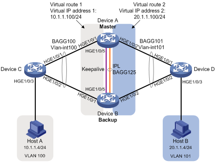
· VLAN 100内主机的缺省网关为10.1.1.100/24,VLAN 101内主机的缺省网关为20.1.1.100/24。Device A和Device B同时属于虚拟IP地址为10.1.1.100/24的备份组1和虚拟IP地址为20.1.1.100/24的备份组2。在备份组1和备份组2中Device A的优先级高于Device B。
图1-8 DRNI三层转发配置组网图
![]()
缺省情况下,本设备的接口处于ADM(Administratively Down)状态,请根据实际需要在对应接口视图下使用undo shutdown命令开启接口。
(1) 配置Device A
# 系统配置。
<DeviceA> system-view
[DeviceA] drni system-mac 1-1-1
[DeviceA] drni system-number 1
[DeviceA] drni system-priority 123
# 配置Keepalive报文的目的IP地址和源IP地址。
[DeviceA] drni keepalive ip destination 1.1.1.2 source 1.1.1.1
# 配置端口HundredGigE1/0/5工作在三层模式,并配置IP地址为Keepalive报文的源IP地址。
[DeviceA] interface hundredgige 1/0/5
[DeviceA-HundredGigE1/0/5] port link-mode route
[DeviceA-HundredGigE1/0/5] ip address 1.1.1.1 24
[DeviceA-HundredGigE1/0/5] quit
# 配置Keepalive链路接口为DRNI保留接口。
[DeviceA] drni mad exclude interface hundredgige 1/0/5
# 创建动态二层聚合接口125,并配置该接口为IPP口。
[DeviceA] interface bridge-aggregation 125
[DeviceA-Bridge-Aggregation125] link-aggregation mode dynamic
[DeviceA-Bridge-Aggregation125] port drni intra-portal-port 1
[DeviceA-Bridge-Aggregation125] quit
# 分别将端口HundredGigE1/0/3和HundredGigE1/0/4加入到聚合组125中。
[DeviceA] interface hundredgige 1/0/3
[DeviceA-HundredGigE1/0/3] port link-aggregation group 125
[DeviceA-HundredGigE1/0/3] quit
[DeviceA] interface hundredgige 1/0/4
[DeviceA-HundredGigE1/0/4] port link-aggregation group 125
[DeviceA-HundredGigE1/0/4] quit
# 创建动态二层聚合接口100,并配置该接口为DR口1。
[DeviceA] interface bridge-aggregation 100
[DeviceA-Bridge-Aggregation100] link-aggregation mode dynamic
[DeviceA-Bridge-Aggregation100] port drni group 1
[DeviceA-Bridge-Aggregation100] quit
# 将端口HundredGigE1/0/1加入到聚合组100中。
[DeviceA] interface hundredgige 1/0/1
[DeviceA-HundredGigE1/0/1] port link-aggregation group 100
[DeviceA-HundredGigE1/0/1] quit
# 创建动态二层聚合接口101,并配置该接口为DR口2。
[DeviceA] interface bridge-aggregation 101
[DeviceA-Bridge-Aggregation101] link-aggregation mode dynamic
[DeviceA-Bridge-Aggregation101] port drni group 2
[DeviceA-Bridge-Aggregation101] quit
# 将端口HundredGigE1/0/2加入到聚合组101中。
[DeviceA] interface hundredgige 1/0/2
[DeviceA-HundredGigE1/0/2] port link-aggregation group 101
[DeviceA-HundredGigE1/0/2] quit
# 创建VLAN 100和101。
[DeviceA] vlan 100
[DeviceA-vlan100] quit
[DeviceA] vlan 101
[DeviceA-vlan101] quit
# 配置二层聚合接口100为Trunk端口,并允许VLAN 100的报文通过。
[DeviceA] interface bridge-aggregation 100
[DeviceA-Bridge-Aggregation100] port link-type trunk
[DeviceA-Bridge-Aggregation100] port trunk permit vlan 100
[DeviceA-Bridge-Aggregation100] quit
# 配置二层聚合接口101为Trunk端口,并允许VLAN 101的报文通过。
[DeviceA] interface bridge-aggregation 101
[DeviceA-Bridge-Aggregation101] port link-type trunk
[DeviceA-Bridge-Aggregation101] port trunk permit vlan 101
[DeviceA-Bridge-Aggregation101] quit
# 配置二层聚合接口125为Trunk端口,并允许VLAN 100和101的报文通过。
[DeviceA] interface bridge-aggregation 125
[DeviceA-Bridge-Aggregation125] port link-type trunk
[DeviceA-Bridge-Aggregation125] port trunk permit vlan 100 101
[DeviceA-Bridge-Aggregation125] quit
# 创建接口Vlan-interface100和Vlan-interface101,并配置其IP地址。
[DeviceA] interface vlan-interface 100
[DeviceA-vlan-interface100] ip address 10.1.1.1 24
[DeviceA-vlan-interface100] quit
[DeviceA] interface vlan-interface 101
[DeviceA-vlan-interface101] ip address 20.1.1.1 24
[DeviceA-vlan-interface101] quit
# 配置Vlan-interface100和Vlan-interface101接口为DRNI保留接口。
[DeviceA] drni mad exclude interface vlan-interface 100
[DeviceA] drni mad exclude interface vlan-interface 101
# 配置OSPF。
[DeviceA] ospf
[DeviceA-ospf-1] import-route direct
[DeviceA-ospf-1] area 0
[DeviceA-ospf-1-area-0.0.0.0] network 10.1.1.0 0.0.0.255
[DeviceA-ospf-1-area-0.0.0.0] network 20.1.1.0 0.0.0.255
[DeviceA-ospf-1-area-0.0.0.0] quit
[DeviceA-ospf-1] quit
# 为接口Vlan-interface100创建备份组1,并配置备份组1的虚拟IP地址为10.1.1.100。
[DeviceA] interface vlan-interface 100
[DeviceA-Vlan-interface100] vrrp vrid 1 virtual-ip 10.1.1.100
# 设置Device A在备份组1中的优先级为200,以保证Device A成为Master,从而和Device A在DRNI中角色一致。
[DeviceA-Vlan-interface100] vrrp vrid 1 priority 200
[DeviceA-Vlan-interface100] quit
# 为接口Vlan-interface101创建备份组2,并配置备份组2的虚拟IP地址为20.1.1.100。
[DeviceA] interface vlan-interface 101
[DeviceA-Vlan-interface101] vrrp vrid 2 virtual-ip 20.1.1.100
# 设置Device A在备份组2中的优先级为200,以保证Device A成为Master,从而和Device A在DRNI中角色一致。
[DeviceA-Vlan-interface101] vrrp vrid 2 priority 200
[DeviceA-Vlan-interface101] quit
(2) 配置Device B
# 系统配置。
<DeviceB> system-view
[DeviceB] drni system-mac 1-1-1
[DeviceB] drni system-number 2
[DeviceB] drni system-priority 123
# 配置Keepalive报文的目的IP地址和源IP地址。
[DeviceB] drni keepalive ip destination 1.1.1.1 source 1.1.1.2
# 配置端口HundredGigE1/0/5工作在三层模式,并配置IP地址为Keepalive报文的源IP地址。
[DeviceB] interface hundredgige 1/0/5
[DeviceB-HundredGigE1/0/5] port link-mode route
[DeviceB-HundredGigE1/0/5] ip address 1.1.1.2 24
[DeviceB-HundredGigE1/0/5] quit
# 配置Keepalive链路接口为DRNI保留接口。
[DeviceB] drni mad exclude interface hundredgige 1/0/5
# 创建动态二层聚合接口125,并配置该接口为IPP口。
[DeviceB] interface bridge-aggregation 125
[DeviceB-Bridge-Aggregation125] link-aggregation mode dynamic
[DeviceB-Bridge-Aggregation125] port drni intra-portal-port 1
[DeviceB-Bridge-Aggregation125] quit
# 分别将端口HundredGigE1/0/3和HundredGigE1/0/4加入到聚合组125中。
[DeviceB] interface hundredgige 1/0/3
[DeviceB-HundredGigE1/0/3] port link-aggregation group 125
[DeviceB-HundredGigE1/0/3] quit
[DeviceB] interface hundredgige 1/0/4
[DeviceB-HundredGigE1/0/4] port link-aggregation group 125
[DeviceB-HundredGigE1/0/4] quit
# 创建动态二层聚合接口100,并配置该接口为DR口1。
[DeviceB] interface bridge-aggregation 100
[DeviceB-Bridge-Aggregation100] link-aggregation mode dynamic
[DeviceB-Bridge-Aggregation100] port drni group 1
[DeviceB-Bridge-Aggregation100] quit
# 将端口HundredGigE1/0/1加入到聚合组100中。
[DeviceB] interface hundredgige 1/0/1
[DeviceB-HundredGigE1/0/1] port link-aggregation group 100
[DeviceB-HundredGigE1/0/1] quit
# 创建动态二层聚合接口101,并配置该接口为DR口2。
[DeviceB] interface bridge-aggregation 101
[DeviceB-Bridge-Aggregation101] link-aggregation mode dynamic
[DeviceB-Bridge-Aggregation101] port drni group 2
[DeviceB-Bridge-Aggregation101] quit
# 将端口HundredGigE1/0/2加入到聚合组101中。
[DeviceB] interface hundredgige 1/0/2
[DeviceB-HundredGigE1/0/2] port link-aggregation group 101
[DeviceB-HundredGigE1/0/2] quit
# 创建VLAN 100和101。
[DeviceB] vlan 100
[DeviceB-vlan100] quit
[DeviceB] vlan 101
[DeviceB-vlan101] quit
# 配置二层聚合接口100为Trunk端口,并允许VLAN 100的报文通过。
[DeviceB] interface bridge-aggregation 100
[DeviceB-Bridge-Aggregation100] port link-type trunk
[DeviceB-Bridge-Aggregation100] port trunk permit vlan 100
[DeviceB-Bridge-Aggregation100] quit
# 配置二层聚合接口101为Trunk端口,并允许VLAN 101的报文通过。
[DeviceB] interface bridge-aggregation 101
[DeviceB-Bridge-Aggregation101] port link-type trunk
[DeviceB-Bridge-Aggregation101] port trunk permit vlan 101
[DeviceB-Bridge-Aggregation101] quit
# 配置二层聚合接口125为Trunk端口,并允许VLAN 100和101的报文通过。
[DeviceB] interface bridge-aggregation 125
[DeviceB-Bridge-Aggregation125] port link-type trunk
[DeviceB-Bridge-Aggregation125] port trunk permit vlan 100 101
[DeviceB-Bridge-Aggregation125] quit
# 创建接口Vlan-interface100和Vlan-interface101,并配置其IP地址。
[DeviceB] interface vlan-interface 100
[DeviceB-vlan-interface100] ip address 10.1.1.2 24
[DeviceB-vlan-interface100] quit
[DeviceB] interface vlan-interface 101
[DeviceB-vlan-interface101] ip address 20.1.1.2 24
[DeviceB-vlan-interface101] quit
# 配置Vlan-interface100和Vlan-interface101接口为DRNI保留接口。
[DeviceB] drni mad exclude interface vlan-interface 100
[DeviceB] drni mad exclude interface vlan-interface 101
# 配置OSPF。
[DeviceB] ospf
[DeviceB-ospf-1] import-route direct
[DeviceB-ospf-1] area 0
[DeviceB-ospf-1-area-0.0.0.0] network 10.1.1.0 0.0.0.255
[DeviceB-ospf-1-area-0.0.0.0] network 20.1.1.0 0.0.0.255
[DeviceB-ospf-1-area-0.0.0.0] quit
[DeviceB-ospf-1] quit
# 为接口Vlan-interface100创建备份组1,并配置备份组1的虚拟IP地址为10.1.1.100。
[DeviceB] interface vlan-interface 100
[DeviceB-Vlan-interface100] vrrp vrid 1 virtual-ip 10.1.1.100
[DeviceB-Vlan-interface100] quit
# 为接口Vlan-interface101创建备份组2,并配置备份组2的虚拟IP地址为20.1.1.100。
[DeviceB] interface vlan-interface 101
[DeviceB-Vlan-interface101] vrrp vrid 2 virtual-ip 20.1.1.100
[DeviceB-Vlan-interface101] quit
(3) 配置Device C
# 创建二层聚合接口100,并配置该接口为动态聚合模式。
<DeviceC> system-view
[DeviceC] interface bridge-aggregation 100
[DeviceC-Bridge-Aggregation100] link-aggregation mode dynamic
[DeviceC-Bridge-Aggregation100] quit
# 分别将端口HundredGigE1/0/1和HundredGigE1/0/2加入到聚合组100中。
[DeviceC] interface range hundredgige 1/0/1 to hundredgige 1/0/2
[DeviceC-if-range] port link-aggregation group 100
[DeviceC-if-range] quit
# 创建VLAN 100。
[DeviceC] vlan 100
[DeviceC-vlan100] quit
# 配置二层聚合接口100为Trunk端口,并允许VLAN 100的报文通过。
[DeviceC] interface bridge-aggregation 100
[DeviceC-Bridge-Aggregation100] port link-type trunk
[DeviceC-Bridge-Aggregation100] port trunk permit vlan 100
[DeviceC-Bridge-Aggregation100] quit
# 配置接口HundredGigE1/0/3为Trunk端口,并允许VLAN 100的报文通过。
[DeviceC] interface hundredgige 1/0/3
[DeviceC-HundredGigE1/0/3] port link-type trunk
[DeviceC-HundredGigE1/0/3] port trunk permit vlan 100
[DeviceC-HundredGigE1/0/3] quit
# 创建接口Vlan-interface100,并配置其IP地址。
[DeviceC] interface vlan-interface 100
[DeviceC-vlan-interface100] ip address 10.1.1.3 24
[DeviceC-vlan-interface100] quit
# 配置OSPF。
[DeviceC] ospf
[DeviceC-ospf-1] import-route direct
[DeviceC-ospf-1] area 0
[DeviceC-ospf-1-area-0.0.0.0] network 10.1.1.0 0.0.0.255
[DeviceC-ospf-1-area-0.0.0.0] quit
[DeviceC-ospf-1] quit
(4) 配置Device D
# 创建二层聚合接口101,并配置该接口为动态聚合模式。
<DeviceD> system-view
[DeviceD] interface bridge-aggregation 101
[DeviceD-Bridge-Aggregation101] link-aggregation mode dynamic
[DeviceD-Bridge-Aggregation101] quit
# 分别将端口HundredGigE1/0/1和HundredGigE1/0/2加入到聚合组101中。
[DeviceD] interface range hundredgige 1/0/1 to hundredgige 1/0/2
[DeviceD-if-range] port link-aggregation group 101
[DeviceD-if-range] quit
# 创建VLAN 101。
[DeviceD] vlan 101
[DeviceD-vlan101] quit
# 配置二层聚合接口101为Trunk端口,并允许VLAN 101的报文通过。
[DeviceD] interface bridge-aggregation 101
[DeviceD-Bridge-Aggregation101] port link-type trunk
[DeviceD-Bridge-Aggregation101] port trunk permit vlan 101
[DeviceD-Bridge-Aggregation101] quit
# 配置接口HundredGigE1/0/3为Trunk端口,并允许VLAN 101的报文通过。
[DeviceD] interface hundredgige 1/0/3
[DeviceD-HundredGigE1/0/3] port link-type trunk
[DeviceD-HundredGigE1/0/3] port trunk permit vlan 101
[DeviceD-HundredGigE1/0/3] quit
# 创建接口Vlan-interface101,并配置其IP地址。
[DeviceD] interface vlan-interface 101
[DeviceD-vlan-interface101] ip address 20.1.1.3 24
[DeviceD-vlan-interface101] quit
# 配置OSPF。
[DeviceD] ospf
[DeviceD-ospf-1] import-route direct
[DeviceD-ospf-1] area 0
[DeviceD-ospf-1-area-0.0.0.0] network 20.1.1.0 0.0.0.255
[DeviceD-ospf-1-area-0.0.0.0] quit
[DeviceD-ospf-1] quit
# 查看Device C上的OSPF邻居信息。
[DeviceC] display ospf peer
OSPF Process 1 with Router ID 10.1.1.3
Neighbor Brief Information
Area: 0.0.0.0
Router ID Address Pri Dead-Time State Interface
20.1.1.1 10.1.1.1 1 37 Full/DR Vlan100
20.1.1.2 10.1.1.2 1 32 Full/BDR Vlan100
以上信息表明Device C与Device A和Device B分别建立OSPF邻居。
# 查看Device D上的OSPF邻居信息。
[DeviceD] display ospf peer
OSPF Process 1 with Router ID 20.1.1.3
Neighbor Brief Information
Area: 0.0.0.0
Router ID Address Pri Dead-Time State Interface
20.1.1.1 20.1.1.1 1 38 Full/DR Vlan101
20.1.1.2 20.1.1.2 1 37 Full/BDR Vlan101
以上信息表明Device C与Device A和Device B分别建立OSPF邻居。
# Host A和Host B可以互相ping通,表明通过DRNI实现三层转发。
不同款型规格的资料略有差异, 详细信息请向具体销售和400咨询。H3C保留在没有任何通知或提示的情况下对资料内容进行修改的权利!


