- 产品与解决方案
- 行业解决方案
- 服务
- 支持
- 合作伙伴
- 关于我们


04-H3C_S12500-S双向PIM典型配置举例
本章节下载: 04-H3C_S12500-S双向PIM典型配置举例 (228.74 KB)
H3C S12500-S双向PIM配置举例
|
Copyright © 2015 杭州华三通信技术有限公司 版权所有,保留一切权利。 非经本公司书面许可,任何单位和个人不得擅自摘抄、复制本文档内容的部分或全部, 并不得以任何形式传播。本文档中的信息可能变动,恕不另行通知。 |
|
目 录
本文档介绍了双向PIM配置举例。
双向PIM(Bidirectional Protocol Independent Multicast,双向协议无关组播)通过建立以RP(Rendezvous Point,汇集点)为中心、分别连接组播源和接收者的双向RPT(Rendezvous Point Tree,共享树),使组播数据沿着双向RPT从组播源经由RP转发到接收者。适用于一个组播组中同时对应多个接收者和多个组播源的组网,例如多方电视电话会议。
本文档中的配置均是在实验室环境下进行的配置和验证,配置前设备的所有参数均采用出厂时的缺省配置。如果您已经对设备进行了配置,为了保证配置效果,请确认现有配置和以下举例中的配置不冲突。
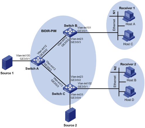
如图1所示,三层交换机Switch A、Switch B和Switch C上均运行OSPF协议,单播路由正常。接收者通过组播方式接收视频点播信息,组播源Source 1和Source 2都向组播组225.1.1.1发送组播信息,末梢用户网络N1和N2中的Host A和Host B均为该组播信息的接收者。
要求在该网络中采用双向PIM协议实现组播数据的分发,以减少三层交换机所维护的组播转发表项数量;同时为了避免因单一RP故障而使通信中断,该网络采用动态RP和静态RP配合方式,来起到RP的备份。
图1 双向PIM配置组网图
|
接口 |
IP地址 |
设备 |
接口 |
IP地址 |
|
|
Switch A |
Vlan-int100 |
10.10.1.1/24 |
Switch C |
Vlan-int102 |
10.102.1.1/24 |
|
|
Vlan-int12 |
10.12.1.1/24 |
|
Vlan-int13 |
10.13.1.3/24 |
|
|
Vlan-int13 |
10.13.1.1/24 |
|
Vlan-int23 |
10.23.1.3/24 |
|
|
|
|
|
Vlan-int33 |
|
|
Switch B |
Vlan-int101 |
10.101.1.1/24 |
Source1 |
- |
10.10.1.2/24 |
|
|
Vlan-int12 |
10.12.1.2/24 |
Source2 |
- |
10.33.1.4/24 |
|
|
Vlan-int23 |
10.23.1.2/24 |
|
|
|
· 选择一台设备的接口作为服务于双向PIM的C-RP,并为该双向PIM域指定一个C-BSR,以负责在双向PIM域中收集并发布RP信息,C-RP和C-BSR可以由同一接口来充当,也可以配置在不同设备上。本例中指定Switch A的VLAN接口12作为C-RP和C-BSR。
· 由于本网络中只配置了一个C-RP,为了避免因单一节点故障而引起的通信中断,可以再配置一个服务于双向PIM的静态RP进行备份。本例中通过将静态RP的IP地址指定为该网络中某网段内但实际不存在的一个地址,从而形成RPL,连接到RPL上的所有接口都可以充当RP,以提供可靠的备份功能。本例中将实际不存在的地址10.13.1.4/24配置为静态RP的地址,从而连接到对应RPL的交换机Switch A、Switch C都可以提供RP的功能。
本举例是在S12500-S-CMW710-R7150P02版本上进行配置和验证的。
· 同一台设备相同实例的所有接口上启用的PIM模式必须相同。
· 双向PIM域内的所有三层交换机上都必须配置完全相同的静态RP。
· 双向PIM域内的所有三层交换机的接口都必须使能PIM-SM。
· 在边界设备连接用户网络的接口上必须使能IGMP功能,以建立和维护各组播组的成员关系。
(1) 使能组播路由功能
<SwitchA> system-view
System View: return to User View with Ctrl+Z.
[SwitchA] multicast routing
[SwitchA-mrib] quit
(2) 配置各接口及接口地址,并使能PIM-SM
# 配置连接组播源Source 1的接口及接口地址,使能PIM-SM。
[SwitchA] vlan 100
[SwitchA-vlan100] port gigabitethernet 3/0/1
[SwitchA-vlan100] quit
[SwitchA] interface vlan-interface 100
[SwitchA-Vlan-interface100] ip address 10.10.1.1 24
[SwitchA-Vlan-interface100] pim sm
[SwitchA-Vlan-interface100] quit
# 配置连接Switch B的接口及接口地址,使能PIM-SM。
[SwitchA] vlan 12
[SwitchA-vlan12] port gigabitethernet 3/0/2
[SwitchA-vlan12] quit
[SwitchA-vlan12] interface vlan-interface 12
[SwitchA-Vlan-interface12] ip address 10.12.1.1 24
[SwitchA-Vlan-interface12] pim sm
[SwitchA-Vlan-interface12] quit
# 配置连接Switch C的接口及接口地址,使能PIM-SM。
[SwitchA] vlan 13
[SwitchA-vlan13] port gigabitethernet 3/0/3
[SwitchA-vlan13] quit
[SwitchA] interface vlan-interface 13
[SwitchA-Vlan-interface13] ip address 10.13.1.1 24
[SwitchA-Vlan-interface13] pim sm
[SwitchA-Vlan-interface13] quit
(3) 配置C-RP和静态RP
# 指定VLAN接口12的IP地址为C-BSR和C-RP。
[SwitchA] pim
[SwitchA-pim] c-bsr 10.12.1.1
[SwitchA-pim] c-rp 10.12.1.1 bidir
# 指定IP地址10.13.1.4为静态RP的IP地址。
[SwitchA-pim] static-rp 10.13.1.4 bidir
(4) 使能双向PIM
[SwitchA-pim] bidir-pim enable
[SwitchA-pim] quit
(5) 配置单播路由协议,以建立正确的单播路由表项
[SwitchA] ospf 1
[SwitchA-ospf-1] import-route direct
[SwitchA-ospf-1] area 0
[SwitchA-ospf-1-area-0.0.0.0] network 10.0.0.0 0.255.255.255
[SwitchA-ospf-1-area-0.0.0.0] quit
[SwitchA-ospf-1] quit
(1) 使能组播路由功能
<SwitchB> system-view
System View: return to User View with Ctrl+Z.
[SwitchB] multicast routing
[SwitchB-mrib] quit
(2) 配置各接口及接口地址,并使能PIM-SM
# 配置连接Switch A的接口及接口地址,使能PIM-SM。
[SwitchB] vlan 12
[SwitchB-vlan12] port gigabitethernet 3/0/2
[SwitchB-vlan12] quit
[SwitchB] interface vlan-interface 12
[SwitchB-Vlan-interface12] ip address 10.12.1.2 24
[SwitchB-Vlan-interface12] pim sm
[SwitchB-Vlan-interface12] quit
# 配置连接Switch C的接口及接口地址,使能PIM-SM。
[SwitchB] vlan 23
[SwitchB-vlan23] port gigabitethernet 3/0/3
[SwitchB-vlan23] quit
[SwitchB] interface vlan-interface 23
[SwitchB-Vlan-interface23] ip address 10.23.1.2 24
[SwitchB-Vlan-interface23] pim sm
[SwitchB-Vlan-interface23] quit
# 配置连接网络N1的接口及接口地址,使能PIM-SM和IGMP(缺省情况下,IGMP的版本为IGMPv2)。
[SwitchB] vlan 101
[SwitchB-vlan101] port gigabitethernet 3/0/1
[SwitchB-vlan101] quit
[SwitchB] interface vlan-interface 101
[SwitchB-Vlan-interface101] ip address 10.101.1.1 24
[SwitchB-Vlan-interface101] pim sm
[SwitchB-Vlan-interface101] igmp enable
[SwitchB-Vlan-interface101] quit
(3) 配置静态RP。指定IP地址10.13.1.4为静态RP的IP地址。
[SwitchB] pim
[SwitchB-pim] static-rp 10.13.1.4 bidir
(4) 使能双向PIM
[SwitchB-pim] bidir-pim enable
[SwitchB-pim] quit
(5) 配置单播路由协议,以建立正确的单播路由表项
[SwitchB] ospf 1
[SwitchB-ospf-1] import-route direct
[SwitchB-ospf-1] area 0
[SwitchB-ospf-1-area-0.0.0.0] network 10.0.0.0 0.255.255.255
[SwitchB-ospf-1-area-0.0.0.0] quit
[SwitchB-ospf-1] quit
(1) 使能组播路由功能
<SwitchC> system-view
System View: return to User View with Ctrl+Z.
[SwitchC] multicast routing
[SwitchC-mrib] quit
(2) 配置各接口及接口地址,并使能PIM-SM
# 配置连接组播源Source 2的接口及接口地址,使能PIM-SM。
[SwitchC] vlan 33
[SwitchC-vlan33] port gigabitethernet 3/0/4
[SwitchC-vlan33] quit
[SwitchC] interface vlan-interface 33
[SwitchC-Vlan-interface33] ip address 10.33.1.3 24
[SwitchC-Vlan-interface33] pim sm
[SwitchC-Vlan-interface33] quit
# 配置连接Switch A的接口及接口地址,使能PIM-SM
[SwitchC] vlan 13
[SwitchC-vlan13] port gigabitethernet 3/0/3
[SwitchC-vlan13] quit
[SwitchC] interface vlan-interface 13
[SwitchC-Vlan-interface13] ip address 10.13.1.3 24
[SwitchC-Vlan-interface13] pim sm
[SwitchC-Vlan-interface13] quit
# 配置连接Switch B的接口及接口地址,使能PIM-SM。
[SwitchC] vlan 23
[SwitchC-vlan23] port gigabitethernet 3/0/2
[SwitchC-vlan23] quit
[SwitchC] interface vlan-interface 23
[SwitchC-Vlan-interface23] ip address 10.23.1.3 24
[SwitchC-Vlan-interface23] pim sm
[SwitchC-Vlan-interface23] quit
# 配置连接网络N2的接口及接口地址,使能PIM-SM和IGMP(缺省情况下,IGMP的版本为IGMPv2)。
[SwitchC] vlan 102
[SwitchC-vlan102] port gigabitethernet 3/0/1
[SwitchC-vlan102] quit
[SwitchC] interface vlan-interface 102
[SwitchC-Vlan-interface102] ip address 10.102.1.1 24
[SwitchC-Vlan-interface102] pim sm
[SwitchC-Vlan-interface102] igmp enable
[SwitchC-Vlan-interface102] quit
(3) 配置静态RP。指定IP地址10.13.1.4为静态RP的IP地址
[SwitchC] pim
[SwitchC-pim] static-rp 10.13.1.4 bidir
(4) 使能双向PIM
[SwitchC-pim] bidir-pim enable
[SwitchC-pim] quit
(5) 配置单播路由协议,以建立正确的单播路由表项
[SwitchC] ospf 1
[SwitchC-ospf-1] import-route direct
[SwitchC-ospf-1] area 0
[SwitchC-ospf-1-area-0.0.0.0] network 10.0.0.0 0.255.255.255
[SwitchC-ospf-1-area-0.0.0.0] quit
[SwitchC-ospf-1] quit
(1) 按照如上配置后,查看配置信息发现Switch A、Switch B和Switch C之间建立了PIM邻居关系。
# 查看Switch A上的PIM邻居信息。
[SwitchA] display pim neighbor
Total Number of Neighbors = 2
Neighbor Interface Uptime Expires DR-Priority Mode
10.12.1.2 Vlan12 00:02:27 00:01:45 1 B
10.13.1.3 Vlan13 00:02:27 00:01:19 1 B
# 查看Switch B上的PIM邻居信息。
[SwitchB] display pim neighbor
Total Number of Neighbors = 2
Neighbor Interface Uptime Expires DR-Priority Mode
10.12.1.1 Vlan12 00:03:05 00:01:44 1 B
10.23.1.3 Vlan23 00:13:49 00:01:29 1 B
# 查看Switch C上的PIM邻居信息。
[SwitchC] display pim neighbor
Total Number of Neighbors = 2
Neighbor Interface Uptime Expires DR-Priority Mode
10.13.1.1 Vlan13 00:03:28 00:01:39 1 B
10.23.1.2 Vlan23 00:14:05 00:01:36 1 B
(2) 通过使用display pim bsr-info命令可以查看PIM-SM域中的BSR信息。
# 查看Switch A上PIM-SM域中的BSR信息。
[SwitchA] display pim bsr-info
Scope: non-scoped
State: Elected
Bootstrap timer: 00:01:18
Elected BSR address: 10.12.1.1
Priority: 64
Hash mask length: 30
Uptime: 00:04:01
Candidate BSR address: 10.12.1.1
Priority: 64
Hash mask length: 30
# 查看Switch B上PIM-SM域中的BSR信息。
[SwitchB] display pim bsr-info
Scope: non-scoped
State: Accept Preferred
Bootstrap timer: 00:00:26
Elected BSR address: 10.12.1.1
Priority: 64
Hash mask length: 30
Uptime: 00:10:41
# 查看Switch C上PIM-SM域中的BSR信息。
[SwitchC] display pim bsr-info
Scope: non-scoped
State: Accept Preferred
Bootstrap timer: 00:02:08
Elected BSR address: 10.12.1.1
Priority: 64
Hash mask length: 30
Uptime: 00:15:41
(3) 通过使用display pim rp-info命令可以查看PIM-SM域中的RP信息。
# 查看Switch A上所有组播组对应的RP信息。
[SwitchA] display pim rp-info
BSR RP information:
Scope: non-scoped
Group/MaskLen: 224.0.0.0/4 [B]
RP address Priority HoldTime Uptime Expires
10.12.1.1 (local) 192 180 00:06:01 00:02:58
Static RP information:
RP address ACL Mode Preferred
10.13.1.4 ---- bidir No
# 查看Switch B上所有组播组对应的RP信息。
[SwatchB] display pim rp-info
BSR RP information:
Scope: non-scoped
Group/MaskLen: 224.0.0.0/4 [B]
RP address Priority HoldTime Uptime Expires
10.12.1.1 192 180 00:06:33 00:02:26
Static RP information:
RP address ACL Mode Preferred
10.13.1.4 ---- bidir No
# 查看Switch C上所有组播组对应的RP信息。
[SwitchC] display pim rp-info
BSR RP information:
Scope: non-scoped
Group/MaskLen: 224.0.0.0/4 [B]
RP address Priority HoldTime Uptime Expires
10.12.1.1 192 180 00:06:51 00:02:05
Static RP information:
RP address ACL Mode Preferred
10.13.1.4 ---- bidir No
(4) 通过使用display pim df-info命令可以查看双向PIM的DF信息。
# 查看Switch A上双向PIM的DF信息
[SwitchA] display pim df-info
RP address: 10.12.1.1
Interface State DF-Pref DF-Metric DF-Uptime DF-Address
Vlan100 Win 0 0 00:01:09 10.10.1.1 (local)
Vlan12 - - - - -
Vlan13 Win 0 0 00:01:10 10.13.1.1 (local)
RP address: 10.13.1.4
Interface State DF-Pref DF-Metric DF-Uptime DF-Address
Vlan100 Win 0 0 00:00:07 10.10.1.1 (local)
Vlan12 Win 0 0 00:00:07 10.12.1.1 (local)
Vlan13 - - - - -
# 查看Switch B上双向PIM的DF信息
[SwatchB] display pim df-info
RP address: 10.12.1.1
Interface State DF-Pref DF-Metric DF-Uptime DF-Address
Vlan12 - - - - -
Vlan23 Win 0 0 00:01:46 10.23.1.2 (local)
Vlan101 Win 0 0 00:01:45 10.101.1.1 (local)
RP address: 10.13.1.4
Interface State DF-Pref DF-Metric DF-Uptime DF-Address
Vlan12 Lose 0 0 00:00:44 10.12.1.1
Vlan23 Lose 0 0 00:00:53 10.23.1.3
Vlan101 Win 10 2 00:00:53 10.101.1.1 (local)
# 查看Switch C上双向PIM的DF信息
[SwitchC] display pim df-info
RP address: 10.12.1.1
Interface State DF-Pref DF-Metric DF-Uptime DF-Address
Vlan102 Win 10 2 00:02:07 10.102.1.1 (local)
Vlan33 Win 10 2 00:02:06 10.33.1.3 (local)
Vlan13 Lose 0 0 00:02:07 10.13.1.1
Vlan23 Lose 0 0 00:02:07 10.23.1.2
RP address: 10.13.1.4
Interface State DF-Pref DF-Metric DF-Uptime DF-Address
Vlan102 Win 0 0 00:01:24 10.102.1.1 (local)
Vlan33 Win 0 0 00:01:23 10.33.1.3 (local)
Vlan13 - - - - -
Vlan23 Win 0 0 00:01:24 10.23.1.3 (local)
(5) 通过使用display multicast forwarding df-info命令可以查看组播转发的DF信息
# 查看Switch A上组播转发的DF信息
[SwitchA] display multicast forwarding df-info
Total 2 RPs, 2 matched
00001. RP address: 10.12.1.1
Flags: 0x0
Uptime: 00:02:42
RPF interface: Vlan-interface12
List of 2 DF interfaces:
1: Vlan-interface100
2: Vlan-interface13
00002. RP address: 10.13.1.4
Flags: 0x0
Uptime: 00:01:41
RPF interface: Vlan-interface13
List of 2 DF interfaces:
1: Vlan-interface100
2: Vlan-interface12
# 查看Switch B上组播转发的DF信息
[SwitchB] display multicast forwarding df-info
Total 2 RPs, 2 matched
00001. RP address: 10.12.1.1
Flags: 0x0
Uptime: 00:03:18
RPF interface: Vlan-interface12
List of 2 DF interfaces:
1: Vlan-interface23
2: Vlan-interface101
00002. RP address: 10.13.1.4
Flags: 0x0
Uptime: 00:02:24
RPF interface: Vlan-interface23
List of 1 DF interfaces:
1: Vlan-interface101
# 查看Switch C上组播转发的DF信息
[SwitchC] display multicast forwarding df-info
Total 2 RPs, 2 matched
00001. RP address: 10.12.1.1
Flags: 0x0
Uptime: 00:03:38
RPF interface: Vlan-interface23
List of 2 DF interfaces:
1: Vlan-interface102
2: Vlan-interface33
00002. RP address: 10.13.1.4
Flags: 0x0
Uptime: 00:02:41
RPF interface: Vlan-interface13
List of 3 DF interfaces:
1: Vlan-interface33
2: Vlan-interface23
3: Vlan-interface102
(6) Host A和Host B指定加入组播组G(225.1.1.1)后,Source 1和Source 2都向组播组225.1.1.1发送组播信息,查看各交换机上的PIM路由表信息,可以看出(*,G)表项总数、PIM的模式、入接口、上游邻居、RPF邻居和下游接口信息。
# 查看Switch A上的PIM路由表信息。
[SwitchA] display pim routing-table
Total 1 (*, G) entry; 0 (S, G) entry
(*, 225.1.1.1)
RP: 10.12.1.1 (local)
Protocol: pim-bidir, Flag: WC LOC ACT
UpTime: 00:21:59
Upstream interface: Vlan-interface12
Upstream neighbor: NULL
RPF prime neighbor: NULL
Downstream interface(s) information:
Total number of downstreams: 1
1: Vlan-interface12
Protocol: pim-bidir, UpTime: 00:21:59, Expires: -
2: Vlan-interface13
Protocol: pim-bidir, UpTime: 00:03:26, Expires: -
# 查看Switch B上的PIM路由表信息。
[SwitchB] display pim routing-table
Total 1 (*, G) entry; 0 (S, G) entry
(*, 225.1.1.1)
RP: 10.12.1.1
Protocol: pim-bidir, Flag: WC LOC ACT
UpTime: 00:23:47
Upstream interface: Vlan-interface12
Upstream neighbor: NULL
RPF prime neighbor: NULL
Downstream interface(s) information:
Total number of downstreams: 3
1: Vlan-interface12
Protocol: pim-bidir, UpTime: 00:23:47, Expires: -
2: Vlan-interface23
Protocol: pim-bidir, UpTime: 00:21:56, Expires: -
3: Vlan-interface101
Protocol: igmp, UpTime: 00:23:47, Expires: -
# 查看Switch C上的PIM路由表信息。
[SwitchC] display pim routing-table
Total 1 (*, G) entry; 0 (S, G) entry
(*, 225.1.1.1)
RP: 10.12.1.1
Protocol: pim-bidir, Flag: WC ACT
UpTime: 00:01:45
Upstream interface: Vlan-interface23
Upstream neighbor: 10.23.1.2
RPF prime neighbor: 10.23.1.2
Downstream interface(s) information:
Total number of downstreams: 2
1: Vlan-interface102
Protocol: igmp, UpTime: 00:01:05, Expires: -
2: Vlan-interface23
Protocol: pim-bidir, UpTime: 00:00:53, Expires: -
· Switch A:
#
ospf 1
area 0.0.0.0
network 10.0.0.0 0.255.255.255
#
vlan 12 to 13
#
vlan 100
#
interface Vlan-interface12
ip address 10.12.1.1 255.255.255.0
pim sm
#
interface Vlan-interface13
ip address 10.13.1.1 255.255.255.0
pim sm
#
interface Vlan-interface100
ip address 10.10.1.1 255.255.255.0
pim sm
#
interface GigabitEthernet3/0/1
port link-mode bridge
port access vlan 100
#
interface GigabitEthernet3/0/2
port link-mode bridge
port access vlan 12
#
interface GigabitEthernet3/0/3
port link-mode bridge
port access vlan 13
#
multicast routing
#
pim
bidir-pim enable
c-bsr 10.12.1.1
c-rp 10.12.1.1 bidir
static-rp 10.13.1.4 bidir
#
· Switch B:
#
ospf 1
area 0.0.0.0
network 10.0.0.0 0.255.255.255
#
vlan 12
#
Vlan 23
#
vlan 101
#
interface Vlan-interface12
ip address 10.12.1.2 255.255.255.0
pim sm
#
interface Vlan-interface23
ip address 10.23.1.2 255.255.255.0
pim sm
#
interface Vlan-interface101
ip address 10.101.1.1 255.255.255.0
pim sm
igmp enable
#
interface GigabitEthernet3/0/1
port link-mode bridge
port access vlan 101
#
interface GigabitEthernet3/0/2
port link-mode bridge
port access vlan 12
#
interface GigabitEthernet3/0/3
port link-mode bridge
port access vlan 23
#
multicast routing
#
pim
bidir-pim enable
static-rp 10.13.1.4 bidir
#
· Switch C:
#
ospf 1
area 0.0.0.0
network 10.0.0.0 0.255.255.255
#
vlan 13
#
vlan 23
#
vlan 33
#
vlan 102
#
interface Vlan-interface13
ip address 10.13.1.3 255.255.255.0
pim sm
#
interface Vlan-interface23
ip address 10.23.1.3 255.255.255.0
pim sm
#
interface Vlan-interface33
ip address 10.33.1.3 255.255.255.0
pim sm
#
interface Vlan-interface102
ip address 10.102.1.1 255.255.255.0
pim sm
igmp enable
#
interface GigabitEthernet3/0/1
port link-mode bridge
port access vlan 102
#
interface GigabitEthernet3/0/2
port link-mode bridge
port access vlan 23
#
interface GigabitEthernet3/0/3
port link-mode bridge
port access vlan 13
#
interface GigabitEthernet3/0/4
port link-mode bridge
port access vlan 33
#
multicast routing
#
pim
bidir-pim enable
static-rp 10.13.1.4 bidir
· H3C S12500-S系列以太网交换机 IP组播配置指导-Release R7150P02
· H3C S12500-S系列以太网交换机 IP组播命令参考-Release R7150P02
不同款型规格的资料略有差异, 详细信息请向具体销售和400咨询。H3C保留在没有任何通知或提示的情况下对资料内容进行修改的权利!


