- Table of Contents
- Related Documents
-
| Title | Size | Download |
|---|---|---|
| 02-IP Tunneling Troubleshooting Guide | 59.39 KB |
Troubleshooting IP tunneling and security VPN
IP tunneling issues
Failure in pinging the IP address of the remote tunnel interface from the local tunnel interface for a P2P tunnel
Symptom
After you configure a P2P tunnel (for example, a GRE, IPv4, or IPv6 tunnel), you cannot ping the IP address of the remote tunnel interface from the IP address of the local tunnel interface.
This section uses a GRE/IPv4 tunnel to describe the troubleshooting procedure.
|
|
NOTE: The troubleshooting procedure in this section is not applicable to P2MP tunnels like DS-Lite and GRE P2MP tunnels. |
Common causes
The following are the common causes of this type of issue:
· Configuration errors. For example, the tunnel modes at the two ends of the tunnel are inconsistent, or no source or destination address is configured on any of the tunnel interfaces attached to the tunnel. Another example is that the source and destination addresses at one end are not the destination and source addresses at the other end, respectively.
· Physical link disconnectivity. The tunnel interface at each end cannot come up because no routes exist between the source and destination addresses of the tunnel. Another case is that the routes for the physical links that the tunnel relies on are all down. In this case, the intermediate devices drop tunneled packets even if the tunnel interfaces at both ends are up.
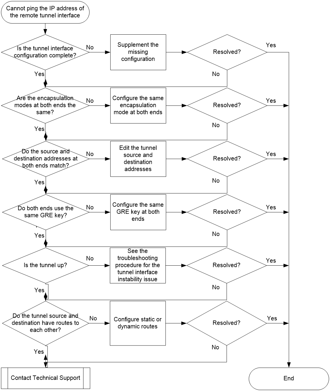
Troubleshooting flow
Figure 1 shows the troubleshooting flowchart.
Solution
1. Verify that the tunnel interface configuration is complete on both ends of the tunnel.
Execute the display current interface tunnel command on both ends of the tunnel to display the tunnel interface configuration. Make sure the tunnel source address, tunnel destination address, and IP address of the tunnel interface have all been configured on each end.
<Sysname> display current interface tunnel
#
interface Tunnel1 mode gre
ip address 10.1.1.1 255.255.255.0
source 1.1.1.1
destination 1.1.1.2
#
If the configuration of the tunnel interface on one end is incomplete, supplement the missing configuration. The following information provides an example of the tunnel interface configuration:
<Sysname> system-view
[Sysname] interface tunnel 1 mode gre
[Sysname-Tunnel1] ip address 10.1.1.1 255.255.255.0
[Sysname-Tunnel1] source 1.1.1.1
[Sysname-Tunnel1] destination 1.1.1.2
2. Verify that the encapsulation modes at both ends of the tunnel are the same.
On each end, execute the display current interface tunnel command to display the encapsulation mode of the tunnel interface.
<Sysname> display current interface tunnel
#
interface Tunnel1 mode gre
ip address 10.1.1.1 255.255.255.0
source 1.1.1.1
destination 1.1.1.2
#
If the encapsulation modes at both ends are inconsistent, you must first execute the undo interface tunnel command to delete the tunnel interface with an incorrect mode, and then execute the interface tunnel command to re-create the tunnel interface. Deleting a tunnel interface also deletes the configuration on that tunnel interface. You must reconfigure the tunnel source address, tunnel destination address, and IP address of the tunnel interface after the tunnel interface is re-created.
3. Verify that the source and destination addresses at one end of the tunnel are the destination and source addresses at the other end of the tunnel, respectively.
On each end, execute the display current interface tunnel command to display the tunnel interface configuration. Make sure the tunnel source address on the local end is the tunnel destination address on the remote end and the tunnel destination address on the local end is the tunnel source address on the remote end. In addition, the tunnel source address on each end must be a local address.
Local end:
<Sysname> display current interface tunnel
#
interface Tunnel1 mode gre
ip address 10.1.1.1 255.255.255.0
source 1.1.1.1
destination 1.1.1.2
#
Remote end:
<Sysname> display current interface tunnel
#
interface Tunnel1 mode gre
ip address 10.1.1.2 255.255.255.0
source 1.1.1.2
destination 1.1.1.1
#
If the tunnel source or destination address on one end is incorrectly configured, execute the source or destination command in tunnel interface view to reconfigure the tunnel source or destination address.
4. Verify that the GRE keys at both ends of the tunnel are identical.
You must configure the same GRE key at both ends of a GRE tunnel, or do not configure any GRE key at both ends of a GRE tunnel. To check the GRE key configuration, execute the display current interface tunnel command on both ends.
Local end:
#
interface Tunnel1 mode gre
ip address 10.1.1.1 255.255.255.0
source 1.1.1.1
destination 1.1.1.2
gre key 123
#
Remote end:
#
interface Tunnel1 mode gre
ip address 10.1.1.2 255.255.255.0
source 1.1.1.2
destination 1.1.1.1
gre key 123
#
If the GRE keys configured on both ends of the tunnel are different, execute the gre key command in tunnel interface view to configure the same GRE key on both ends.
5. Verify that the tunnel interfaces at both ends are already up.
Execute the display interface tunnel command to display the tunnel interface state. If the tunnel interface on one end is still down after you perform steps 1 and 2, see "Tunnel interface instability" in Tunnel Interface Troubleshooting Guide.
#
<Sysname> display interface tunnel 1
Current state: UP
Line protocol state: UP
Description: Tunnel1 Interface
Bandwidth: 64kbps
Maximum transmission unit: 1476
Internet address: 10.1.2.1/24 (primary)
Tunnel source 2002::1:1 (Vlan-interface10), destination 2001::2:1
Tunnel TOS 0xC8, Tunnel TTL 255
Tunnel protocol/transport GRE/IPv6
...
#
6. Verify that the source and destination IP addresses of the tunnel have routes to reach each other.
Execute the display current interface tunnel command to identify whether the IP addresses of the tunnel interfaces at both ends of the tunnel belong to the same subnet. If they belong to the same subnet, the two ends will generate subnet routes by default. In this case, no physical link disconnectivity issue exists. If they do not belong to the same subnet, execute the display fib command to identify whether the source and destination IP addresses of the tunnel have routes to reach each other. If no routes are available, you must configure static or dynamic routes to make sure the source and destination IP addresses of the tunnel have routes to reach each other. If the issue persists, proceed to step 7.
#
<Sysname> display fib
Route destination count: 4
Directly-connected host count: 0
Flag:
U:Useable G:Gateway H:Host B:Blackhole D:Dynamic S:Static
R:Relay F:FRR
Destination/Mask Nexthop Flag OutInterface/Token Label
0.0.0.0/32 127.0.0.1 UH InLoop0 Null
1.1.1.2/24 192.168.126.1 USGF M-GE0/0/0 Null
127.0.0.0/8 127.0.0.1 U InLoop0 Null
127.0.0.0/32 127.0.0.1 UH InLoop0 Null
#
7. If the issue persists, collect the following information and contact Technical Support:
¡ Results of each step.
¡ The configuration file, log messages, and alarm messages.
¡ Command output from the debugging commands in Table 1.
|
Command |
Description |
|
debugging tunnel |
Enable tunneling debugging. |
|
debugging ip packet [ acl acl-number ] |
Enable IP packet debugging. |
|
debugging ipv6 packet [ acl acl-number ] |
Enable IPv6 packet debugging. |
|
debugging ip error |
Enable IP forwarding error debugging. |
|
debugging ip info [ acl acl-number ] |
Enable IP forwarding debugging. |
|
debugging ipv6 info [ acl acl-number ] |
Enable IPv6 forwarding debugging. |
Related alarm and log messages
Alarm messages
N/A
Log messages
N/A
