- Table of Contents
- Related Documents
-
| Title | Size | Download |
|---|---|---|
| 01-IPsec Troubleshooting Guide | 106.96 KB |
Troubleshooting IP tunnels and IPsec VPNs
IPsec issues
Failures in triggering IKE negotiations (using an IPsec profile)
Symptom
As shown in Figure 1, an IKE-based IPsec tunnel needs to be established between Device A and Device B to protect the private network traffic between Host A and Host B. The encapsulation mode for the IPsec tunnel is the tunnel mode. After completing the configuration on Device A and Device B, traffic fails to be forwarded between Host A and Host B.
After you execute the display ike sa command on Device A, no information is displayed, which indicates that the phase-1 IKE negotiation was unsuccessful. RD is displayed in the Flag field after you execute the display ike sa command and no information is displayed after you execute the display ipsec sa command. This indicates that the phase-2 IKE negotiation was also unsuccessful.
<DeviceA> display ike sa
Flags:
RD--READY RL--REPLACED FD-FADING RK-REKEY
ID Profile Remote Flag Remote-Type Remote-ID
--------------------------------------------------------------------
<DeviceA> display ipsec sa
<DeviceA>
When you execute the display ike statistics command on Device A to view IKE statistics, no noticeable error is found.
<DeviceA> display ike statistics
IKE statistics:
No matching proposal: 0
Invalid ID information: 0
Unavailable certificate: 0
Unsupported DOI: 0
Unsupported situation: 0
Invalid proposal syntax: 0
Invalid SPI: 0
Invalid protocol ID: 0
Invalid certificate: 0
Authentication failure: 0
…
After you execute the display ipsec statistics command on Device A to view IPsec statistics, no noticeable error is found.
<DeviceA> display ipsec statistics
IPsec packet statistics:
Received/sent packets: 0/0
Received/sent bytes: 0/0
Received/sent packet rate: 0/0 packets/sec
Received/sent byte rate: 0/0 bytes/sec
Dropped packets (received/sent): 0/0
Dropped packets statistics
No available SA: 0
Wrong SA: 0
Invalid length: 0
Authentication failure: 0
Encapsulation failure: 0
Decapsulation failure: 0
Replayed packets: 0
ACL check failure: 0
MTU check failure: 0
Loopback limit exceeded: 0
Crypto speed limit exceeded: 0

Common causes
The following are the common causes of this type of issue:
· The route between IPsec gateways is unreachable.
· The IPsec profile configuration is incorrect.
· The configurations of the IKE profiles and IKE proposals are incorrect.
Troubleshooting flow
Figure 2 shows the troubleshooting flowchart.

Solution
1. Check whether the IPsec gateways can ping each other:
Use the ping command to check the network connectivity.
a. If the ping is unsuccessful, continue troubleshooting according to the procedures for troubleshooting ping failures in Troubleshooting Layer 3—IP Services. Make sure Host A and Host B can ping their respective IPsec gateways, and the IPsec gateways can ping each other.
b. If the issue persists, go to step 2.
2. Check whether the IPsec profile configurations are correct:
a. Execute the display ipsec profile command to check whether the configurations on the local IPsec gateway Device A and the peer IPsec gateway Device B are complete. Verify that both transform set and IKE profile have been configured on each device. Make sure security proposals with the same encryption algorithm, authentication algorithm, and PFS are configured on the devices.
For example, the output on Device A is as follows:
[DeviceA] display ipsec profile
-------------------------------------------
IPsec profile: myprofile
Mode: isakmp
-------------------------------------------
Transform set: tran1
IKE profile: profile
SA duration(time based): 3600 seconds
SA duration(traffic based): 1843200 kilobytes
SA soft-duration buffer(time based): 1000 seconds
SA soft-duration buffer(traffic based): 43200 kilobytes
SA idle time: 100 seconds
[DeviceA] display ipsec transform-set
IPsec transform set: tran1
State: complete
Encapsulation mode: tunnel
ESN: Enabled
PFS:
Transform: AH-ESP
AH protocol:
Integrity: SHA1
ESP protocol:
Integrity: SHA1
Encryption: AES-CBC-128
The output on Device B is as follows:
[DeviceB] display ipsec profile
-------------------------------------------
IPsec profile: myprofile
Mode: isakmp
-------------------------------------------
Transform set: tran1
IKE profile: profile
SA duration(time based): 3600 seconds
SA duration(traffic based): 1843200 kilobytes
SA soft-duration buffer(time based): 1000 seconds
SA soft-duration buffer(traffic based): 43200 kilobytes
SA idle time: 100 seconds
[DeviceB] display ipsec transform-set
IPsec transform set: tran1
State: complete
Encapsulation mode: tunnel
ESN: Enabled
PFS:
Transform: AH-ESP
AH protocol:
Integrity: SHA1
ESP protocol:
Integrity: SHA1
Encryption: AES-CBC-128
b. If the issue persists, go to step 3.
3. Check whether the IPsec profiles are correctly configured on the tunnel interfaces.
a. Execute the interface tunnel command on the IPsec gateway Device A to enter tunnel interface Tunnel 1. Execute the display this command to check whether the local and peer addresses and the IPsec profile are configured correctly on the tunnel interface.
[DeviceA] interface tunnel 1
[DeviceA-Tunnel1] display this
#
interface Tunnel1 mode ipsec
ip address 3.3.3.1 255.255.255.0
source 2.2.2.1
destination 2.2.3.1
tunnel protection ipsec profile myprofile
[DeviceA-Tunnel1] quit
If configuration errors exist, modify the configuration as follows:
[DeviceA] interface tunnel 1 mode ipsec
[DeviceA-Tunnel1] ip address 3.3.3.1 255.255.255.0
[DeviceA-Tunnel1] source 2.2.2.1
[DeviceA-Tunnel1] destination 2.2.3.1
[DeviceA-Tunnel1] tunnel protection ipsec profile myprofile
[DeviceA-Tunnel1] quit
b. Execute the interface tunnel command on the IPsec gateway Device B to enter tunnel interface Tunnel 1. Execute the display this command to check whether the local and peer addresses and the IPsec profile are configured correctly on the tunnel interface.
[DeviceB] interface tunnel 1
[DeviceB-Tunnel1] display this
#
interface Tunnel1 mode ipsec
ip address 3.3.3.2 255.255.255.0
source 2.2.3.1
destination 2.2.2.1
tunnel protection ipsec profile myprofile
[DeviceB-Tunnel1] quit
If configuration errors exist, modify the configuration as follows:
[DeviceB] interface tunnel 1 mode ipsec
[DeviceB-Tunnel1] ip address 3.3.3.2 255.255.255.0
[DeviceB-Tunnel1] source 2.2.3.1
[DeviceB-Tunnel1] destination 2.2.2.1
[DeviceB-Tunnel1] tunnel protection ipsec profile myprofile
[DeviceB-Tunnel1] quit
c. If the issue persists, go to step 4.
4. Check whether the IKE profile and IKE proposal configurations are correct.
a. Check the IKE profile configuration on each device. Verify that the local and peer IPsec gateway addresses are configured correctly. If preshared key authentication is used, the preshared keys configured (using the pre-shared-key command) on the local and peer ends must be the same. If RSA signature or digital envelope authentication is used, make sure the digital certificate is within the validity period (displayed in the Validity field of the output for the display pki certificate domain command).
For example, the IKE profile configuration on Device A is as follows:
[DeviceA] ike keychain keychain1
[DeviceA-ike-keychain-keychain1] pre-shared-key address 2.2.3.1 255.255.255.0 key simple 123456TESTplat&!
[DeviceA-ike-keychain-keychain1] quit
[DeviceA] ike profile profile
[DeviceA-ike-profile-profile] keychain keychain1
[DeviceA-ike-profile-profile] local-identity address 2.2.2.1
[DeviceA-ike-profile-profile] match remote identity address 2.2.3.1 255.255.255.0
[DeviceA-ike-profile-profile] quit
The IKE profile configuration on Device B is as follows:
[DeviceB] ike keychain keychain1
[DeviceB-ike-keychain-keychain1] pre-shared-key address 2.2.2.1 255.255.255.0 key simple 123456TESTplat&!
[DeviceB-ike-keychain-keychain1] quit
[DeviceB] ike profile profile
[DeviceB-ike-profile-profile] keychain keychain1
[DeviceB-ike-profile-profile] local-identity address 2.2.3.1
[DeviceB-ike-profile-profile] match remote identity address 2.2.2.1 255.255.255.0
[DeviceB-ike-profile-profile] quit
b. Execute the display ike proposal command on IPsec gateways Device A and Device B respectively to view the IKE proposal configurations. Verify that the IKE proposal configurations are consistent.
[DeviceA] display ike proposal
Priority Authentication Authentication Encryption Diffie-Hellman Duration
method algorithm algorithm group (seconds)
-----------------------------------------------------------------
default PRE-SHARED-KEY SHA1 DES-CBC Group 1 86400
[DeviceB] display ike proposal
Priority Authentication Authentication Encryption Diffie-Hellman Duration
method algorithm algorithm group (seconds)
-----------------------------------------------------------------
default PRE-SHARED-KEY SHA1 DES-CBC Group 1 86400
c. If the issue persists, go to step 5.
5. If the issue persists, collect the following information and contact Technical Support:
¡ Results of each step.
¡ The configuration file, log messages, and alarm messages.
¡ Collected information related to establishment of the IPsec tunnel after you execute the debugging commands as follows.
<DeviceA> terminal debugging
The current terminal is enabled to display debugging logs.
<DeviceA> terminal monitor
The current terminal is enabled to display logs.
<DeviceA> debugging ike all
<DeviceA> debugging ipsec all
IPsec SA negotiation failed in IKE aggressive mode
Symptom
The display ike sa command shows that the IKE SA negotiation succeeded and the IKE SA is in RD state, but the display ipsec sa command shows that the expected IPsec SA has not been negotiated yet.
<Router> display ike sa
Connection-ID Remote Flag DOI
----------------------------------------------------------
2 10.1.1.1/500 RD IPsec
Flags:
RD--READY RL--REPLACED FD-FADING RK-REKEY
<Router>display ipsec sa
<Router>
Solution
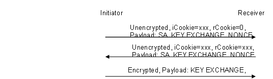
The process of phase 1 IKE negotiation in aggressive mode is as follows:
1. Check all IKE debugging information on the initiator.
Execute the debugging ike all command on the initiator to identify whether the packet exchange is normal during negotiation.
The key debugging information on the initiator is as follows:
*Nov 7 09:23:08:808 2014 ROUTER IKE/7/DEBUG: send message: //Sent the first packet.
*Nov 7 09:23:08:808 2014 ROUTER IKE/7/DEBUG: ICOOKIE: 0xb8a20d7c014806fa
*Nov 7 09:23:08:808 2014 ROUTER IKE/7/DEBUG: RCOOKIE: 0x0000000000000000
…………………
*Nov 7 09:23:09:365 2014 ROUTER IKE/7/DEBUG: exchange state machine(I): finished step 0, advancing...
*Nov 7 09:23:09:415 2014 ROUTER IKE/7/DEBUG: received message: //Received a response packet.
*Nov 7 09:23:09:516 2014 ROUTER IKE/7/DEBUG: ICOOKIE: 0xb8a20d7c014806fa
*Nov 7 09:23:09:566 2014 ROUTER IKE/7/DEBUG: RCOOKIE: 0x67a9145eb46c41d9
…………………
*Nov 7 09:23:13:510 2014 ROUTER IKE/7/DEBUG: exchange state machine(I): finished step 1, advancing...
…………………
*Nov 7 09:23:14:820 2014 ROUTER IKE/7/DEBUG: send message: Sent the second packet.
*Nov 7 09:23:14:920 2014 ROUTER IKE/7/DEBUG: ICOOKIE: 0xb8a20d7c014806fa
*Nov 7 09:23:14:971 2014 ROUTER IKE/7/DEBUG: RCOOKIE: 0x67a9145eb46c41d9
…………………
*Nov 7 09:23:15:524 2014 ROUTER IKE/7/DEBUG: exchange state machine(I): finished step 2, advancing... //Phase 1 IKE negotiation ended.
…………………
*Nov 7 09:23:21:801 2014 ROUTER IKE/7/DEBUG: send message: //Sent the first packet in phase 2 IKE negotiation.
*Nov 7 09:23:21:902 2014 ROUTER IKE/7/DEBUG: ICOOKIE: 0xb8a20d7c014806fa
*Nov 7 09:23:22:002 2014 ROUTER IKE/7/DEBUG: RCOOKIE: 0x67a9145eb46c41d9
…………………
*Nov 7 09:23:22:506 2014 ROUTER IKE/7/DEBUG: exchange state machine(I): finished step 0, advancing...
*Nov 7 09:23:22:606 2014 ROUTER IKE/7/DEBUG: received message: //Received a response packet.
*Nov 7 09:23:22:657 2014 ROUTER IKE/7/DEBUG: ICOOKIE: 0xb8a20d7c014806fa
*Nov 7 09:23:22:757 2014 ROUTER IKE/7/DEBUG: RCOOKIE: 0x67a9145eb46c41d9
…………………
*Nov 7 09:23:24:571 2014 ROUTER IKE/7/DEBUG: validate payload NOTIFY
*Nov 7 09:23:24:621 2014 ROUTER IKE/7/DEBUG: DOI: IPSEC
*Nov 7 09:23:24:722 2014 ROUTER IKE/7/DEBUG: PROTO: IPSEC_ESP
*Nov 7 09:23:24:822 2014 ROUTER IKE/7/DEBUG: SPI_SZ: 4
*Nov 7 09:23:24:873 2014 ROUTER IKE/7/DEBUG: MSG_TYPE: INVALID_ID_INFORMATION//Received a reply packet of the INVALID_ID_INFORMATION type. The negotiation failed.
*Nov 7 09:23:24:973 2014 ROUTER IKE/7/DEBUG: exchange setup(R): 9c16530
*Nov 7 09:23:25:024 2014 ROUTER IKE/7/DEBUG: exchange check: checking for required INFO
*Nov 7 09:23:25:124 2014 ROUTER IKE/7/DEBUG: got NOTIFY of type INVALID_ID_INFORMATION
The debugging information shows that the three packets exchanged in phase 1 negotiation were normal. However, after the initiator sent the first packet in phase 2 negotiation, it received an INVALID_ID_INFORMATION packet, and the negotiation could not continue.
2. Check all IKE debugging information on the responder.
Execute the debugging ike all command on the responder to identify whether the packet exchange is normal during negotiation.
The key debugging information on the responder is as follows:
*Nov 6 17:03:05:527 2014 ROUTER IKE/7/Event: IKE thread 366519722672 processes a job.
*Nov 6 17:03:05:527 2014 ROUTER IKE/7/Packet: Begin a new phase 1 negotiation as responder.
*Nov 6 17:03:05:527 2014 ROUTER IKE/7/Event: Responder created an SA for peer 10.1.1.1, local port 500, remote port 500.
*Nov 6 17:03:05:527 2014 ROUTER IKE/7/Event: Set IKE SA state to IKE_P1_STATE_INIT.
*Nov 6 17:03:05:527 2014 ROUTER IKE/7/Packet: Received ISAKMP Security Association Payload. //Received the first packet from the initiator.
………
*Nov 6 17:03:05:527 2014 ROUTER IKE/7/Packet: The profile 1 is matched. // Matched IKE profile 1.
……….
*Nov 6 17:03:05:528 2014 ROUTER IKE/7/Event: Found pre-shared key in keychain 1 matching address 10.1.1.1. //Matched a keychain.
……….
*Nov 6 17:03:05:535 2014 ROUTER IKE/7/Event: IKE SA state changed from IKE_P1_STATE_INIT to IKE_P1_STATE_SEND2.
*Nov 6 17:03:05:535 2014 ROUTER IKE/7/Packet: Sending packet to 10.1.1.1 remote port 500, local port 500. //Sent a response packet.
………..
*Nov 6 17:03:05:739 2014 ROUTER IKE/7/Packet: Received packet from 10.1.1.1 source port 500 destination port 500. //Received the second packet from the initiator.
…………….
*Nov 6 17:03:05:741 2014 ROUTER IKE/7/Event: IKE SA state changed from IKE_P1_STATE_SEND2 to IKE_P1_STATE_ESTABLISHED. //Phase 1 IKE negotiation ended.
*Nov 6 17:03:05:741 2014 ROUTER IKE/7/Event: Add tunnel, alloc new tunnel with ID [1].
*Nov 6 17:03:05:983 2014 ROUTER IKE/7/Packet: Received packet from 10.1.1.1 source port 500 destination port 500. //Received the first packet from the initiator in phase 2 IKE negotiation.
………….
*Nov 6 17:03:05:984 2014 ROUTER IKE/7/Event: IPsec SA state changed from IKE_P2_STATE_INIT to IKE_P2_STATE_GETSP.
*Nov 6 17:03:05:985 2014 ROUTER IKE/7/Error: Failed to get IPsec policy for phase 2 responder. Delete IPsec SA.
*Nov 6 17:03:05:985 2014 ROUTER IKE/7/Error: Failed to negotiate IPsec SA. //No matching IPsec policy was found. IPsec SA negotiation failed.
*Nov 6 17:03:05:985 2014 ROUTER IKE/7/Event: Delete IPsec SA.
*Nov 6 17:03:05:985 2014 ROUTER IKE/7/Packet: Encrypt the packet.
*Nov 6 17:03:05:985 2014 ROUTER IKE/7/Packet: Construct notification packet: INVALID_ID_INFORMATION.
*Nov 6 17:03:05:985 2014 ROUTER IKE/7/Packet: Sending packet to 10.1.1.1 remote port 500, local port 500. //Notified the initiator of the failure.
The debugging information shows that the responder failed to find a matching IPsec policy, which led to the IPsec SA negotiation failure.
3. Check the IPsec policy on the responder.
The IPsec policy configuration on the responder is as follows:
ipsec policy hzbank 7000 isakmp
transform-set 1
security acl 3000
ike-profile 1
reverse-route dynamic
reverse-route tag 10
The output shows that no remote IP address was configured in the IPsec policy.
Execute the remote-address command to configure the remote IP address.
[Router]ipsec policy hzbank 7000 isakmp
[Router-ipsec-policy-isakmp-hzbank-7000]remote-address 10.1.1.1
|
|
NOTE: This remote IP address configuration is required on the IKE negotiation initiator and optional on the responder if the responder uses an IPsec policy template. If the responder does not use an IPsec policy template, the remote IP address must be configured. |
5. Identify whether the traffic to be protected on the initiator is the same as that on the responder.
IPsec uses ACLs to identify the traffic to be protected. Make sure the ACL rules in an IPsec policy are correctly configured, and make sure the ACL rules on one device are the mirror images of the rules on the peer device. For example, on IPsec peers A and B, if the ACL rule in the IPsec policy on device B is b->a, the ACL rule in the IPsec policy on device A must be a->b.
If the ACL rules on IPsec peers do not form mirror images of each other, SAs can be set up only when the range specified by an ACL rule on the initiator is covered by its counterpart ACL rule on the receiver. For example:
The ACL configuration on the initiator is as follows:
acl number 3001
rule 5 permit ip source 168.201.0.0 0.0.0.7 destination 168.68.2.200 0
rule 25 permit ip source 168.201.0.0 0.0.0.7 destination 168.201.255.1 0
The ACL configuration on the responder is as follows:
acl number 3000
rule 7 permit ip source 168.68.2.200 0 destination 168.201.0.0 0.0.127.255
A flow (168.201.0.0/29 -> 168.201.255.1) in the ACL on the initiator does not exist on the responder.
Modify the ACL on the responder as follows:
acl number 3000
rule 7 permit ip source 168.68.2.200 0 destination 168.201.0.0 0.0.127.255
rule 10 permit ip source 168.201.255.1 0 destination 168.201.0.0 0.0.127.255
After the flow is added on the responder, the IPsec negotiation succeeds.
|
|
NOTE: If the receiver uses an IPsec policy template, the ACL is optional. If no ACL is specified, the IPsec protection range has no limit. So the receiver accepts all ACL settings of the negotiation initiator. If an ACL is configured, all the rules of the ACL must comply with the previous requirements. |
