- Table of Contents
- Related Documents
-
| Title | Size | Download |
|---|---|---|
| 01-Internet Access Configuration Examples | 218.94 KB |
Introduction
The following information provides an example for configuring the router to access the Internet through a physical interface or mobile communication modem.
Prerequisites
This document is not restricted to specific software or hardware versions. Procedures and information in the examples might be slightly different depending on the software or hardware version of the device.
The configuration examples were created and verified in a lab environment, and all the devices were started with the factory default configuration. When you are working on a live network, make sure you understand the potential impact of every command on your network.
The following information is provided based on the assumption that you have basic knowledge of Point-to-Point Protocol over Ethernet (PPPoE), Dynamic Host Configuration Protocol (DHCP), and mobile communication modem.
Software versions used
This configuration example was created and verified on Release 9141P22 of the SR6602-IE router.
Example: Configuring Internet access through a physical interface
Network configuration
As shown in Figure 1, the WAN interface on the router is connected to the WAN. Users can access the Internet through the WAN interface.

Procedure
# Specify the WAN access scenario for the router as single-WAN scenario. Configure network access settings as follows:
1. Configure a route between PC and Router. (Details not shown.)
2. Access the Web management interface of Router, and navigate to the Network > WAN Settings page.
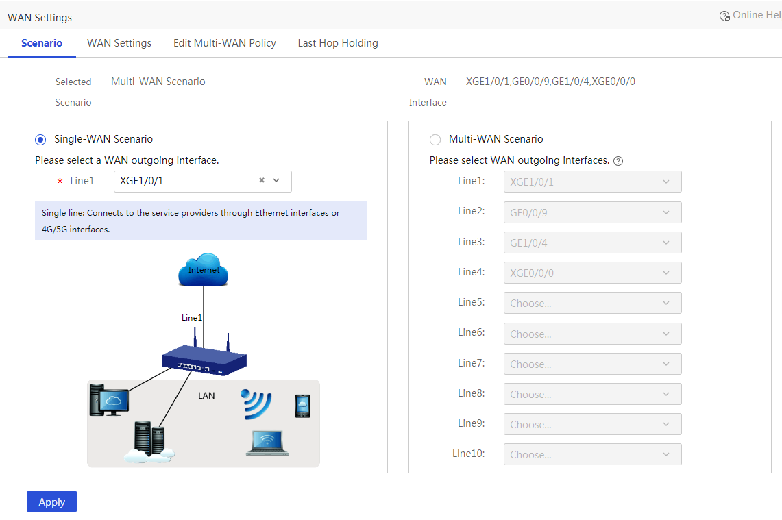
3. Click the Scene tab, and select Single-WAN Scenario.
4. Select the physical interface for Line1. In this example, select WAN1 (XGE1/0/1).
Figure 2 Configuring WAN settings
5. Click the WAN Settings tab to access the WAN configuration page.
6. Click the Edit icon in the Actions column for WAN1 to enter the Edit WAN Settings page.
7. Select a connection mode based on the actual network access mode of the user, and configure associated parameters.
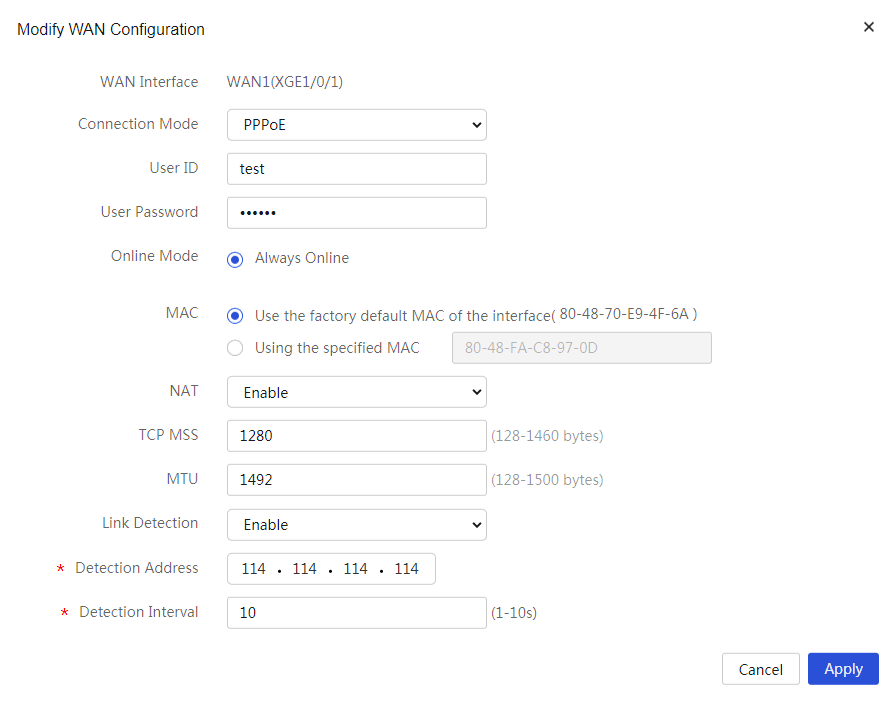
¡ If you select PPPoE for Connection Mode:
- Enter the PPPoE access username provided by the ISP for User ID. In this example, enter test.
- Enter the PPPoE access password provided by the ISP for User Password. In this example, enter 123456.
- Select Always Online for Online Mode.
- For the MAC field, because the ISP does not require binding a MAC address, use the default MAC address for the interface.
- Enable NAT.
- Set the TCP MSS and MTU fields for the interface. This example uses the default values for the TCP MSS and MTU.
- Select Enable for Link Detection, and specify the detection address and detection interval. In this example, enter 114.114.114.114 for Detection Address and 10 for Detection Interval.
Figure 3 Configuring the WAN connection mode as PPPoE
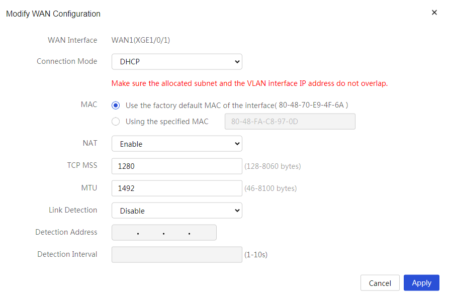
¡ If you select DHCP for Connection Mode, the router will automatically obtain a public IP address through the DHCP server to access the WAN:
- For the MAC field, because the ISP does not require binding a MAC address, use the default MAC address for the interface.
- Enable NAT.
- Set the TCP MSS and MTU fields for the interface. This example uses the default values for the TCP MSS and MTU.
Figure 4 Configuring the WAN connection mode as DHCP
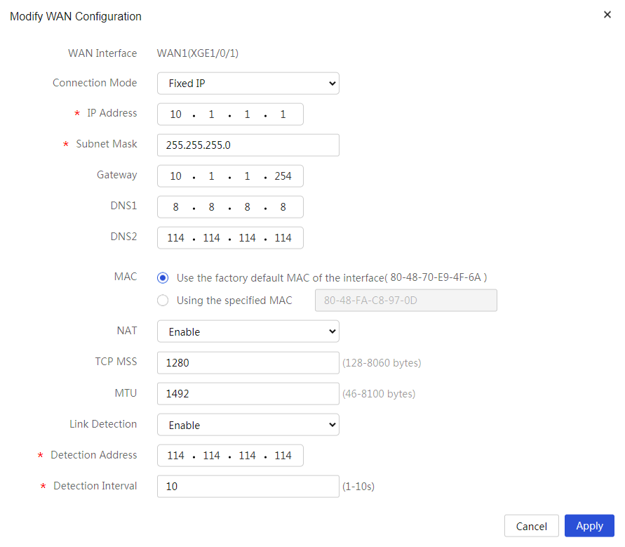
¡ If you select Fixed IP for Connection Mode:
- Enter the IP address to access the WAN in the IP Address field. In this example, enter 10.1.1.1.
- Enter 255.255.255.0 or 24 for Subnet Mask.
- Enter the gateway address to access the WAN in Gateway field. In this example, enter 10.1.1.254.
- Enter the DNS server addresses for DNS1 and DNS2. In this example, enter 8.8.8.8 for DNS1 and 114.114.114.114 for DNS2.
- For the MAC field, because the ISP does not require binding a MAC address, use the default MAC address for the interface.
- Enable NAT.
- Set the TCP MSS and MTU fields for the interface. This example uses the default values for the TCP MSS and MTU.
- Select Enable for Link Detection, and specify the detection address and detection interval. In this example, enter 114.114.114.114 for Detection Address and 10 for Detection Interval.
Figure 5 Configuring the WAN connection mode as fixed IP
8. Click Apply.
