- Table of Contents
- Related Documents
-
| Title | Size | Download |
|---|---|---|
| 05-EVPN L3VPN configuration | 572.83 KB |
Configuring an EVPN L3VPN network
Enabling MPLS encapsulation for IP prefix advertisement routes
Enabling EVPN to advertise VPN routes
Enabling communication between EVPN L3VPN and MPLS L3VPN
About communication between EVPN L3VPN and MPLS L3VPN
Enabling BGP VPNv4 or VPNv6 route advertisement for the BGP EVPN address family
Enabling BGP EVPN route advertisement for the BGP VPNv4 or VPNv6 address family
Enabling the VPN Prefix ORF feature
Display and maintenance commands for EVPN L3VPN
EVPN L3VPN configuration examples
Example: Configuring IPv4 EVPN L3VPN
Example: Configuring IPv6 EVPN L3VPN
Example: Enabling communication between IPv4 MPLS L3VPN and IPv4 EVPN L3VPN
Example: Enabling communication between IPv6 MPLS L3VPN and IPv6 EVPN L3VPN
Configuring EVPN L3VPN
About EVPN L3VPN
EVPN supports using MPLS L3VPN for traffic forwarding in the data plane, which is called EVPN L3VPN. EVPN L3VPN provides fast deployment of Layer 2 networks and can convey both Layer 2 and Layer 3 VPN services. In an EVPN L3VPN network, VPN routes are advertised through IP prefix advertisement routes.
Route advertisement
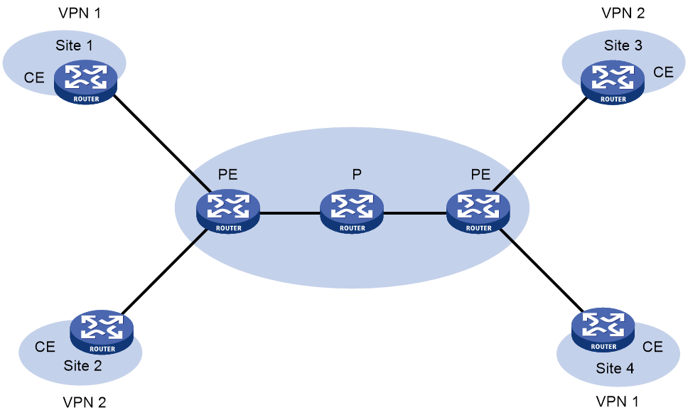
As shown in Figure 1, in an EVPN L3VPN network, CEs and PEs advertises VPN routing information. P routers maintain only the routes within the backbone. A PE maintains only routing information for directly connected VPNs, rather than for all VPNs.
VPN routing information is advertised through the path local CE—ingress PE—egress PE—remote CE.
Figure 1 EVPN L3VPN network model
Route advertisement from the local CE to the ingress PE
The CE advertises standard IPv4 or IPv6 routing information to the ingress PE over a static route, RIP route, OSPF route, IS-IS route, EBGP route, or IBGP route.
Route advertisement from the ingress PE to the egress PE
The ingress PE performs the following operations:
1. Adds RDs and route target attributes to these standard IPv4 or IPv6 routes to create VPN-IPv4 or VPN-IPv6 routes.
2. Assigns MPLS private network labels to the routes to create IP prefix advertisement routes.
3. Advertises the IP prefix advertisement routes to the egress PE.
The egress PE then adds the IP prefix advertisement routes to the routing table of the VPN instance of which an import target matches an export target of the routes.
Route advertisement from the egress PE to the remote CE
The remote CE learns VPN routes from the egress PE through static routes, RIP routes, OSPF routes, IS-IS routes, EBGP routes, or IBGP routes.
Traffic forwarding
In an EVPN L3VPN network, a PE adds the following information into VPN packets:
· Outer tag—Identifies the public tunnel from the local PE to the remote PE. Based on the outer tag, a VPN packet can be forwarded along the public tunnel to the remote PE. The public tunnel can be an LSP, an MPLS TE tunnel, or a GRE tunnel. For a GRE public tunnel, the outer tag is the GRE encapsulation. For an LSP or MPLS TE tunnel, the outer tag is an MPLS label.
· Inner label—Identifies the remote site. The remote PE uses the inner label to forward packets to the target site of the matching VPN instance. PEs advertise the inner labels assigned to private network routes when advertising BGP EVPN routes.
Figure 2 EVPN L3VPN traffic forwarding

As shown in Figure 2, a VPN packet is forwarded from Site 1 to Site 2 by using the following process:
1. Site 1 sends an IP packet with the destination address 1.1.1.2. CE 1 transmits the packet to PE 1.
2. PE 1 performs the following operations:
a. Finds the matching VPN route based on the inbound interface and destination address of the packet.
b. Labels the packet with both the inner label and the outer tag.
c. Forwards the packet to the public tunnel.
3. P devices forward the packet to PE 2 by the outer tag. If the outer tag is GRE encapsulation, PE 2 removes the GRE encapsulation.
4. PE 2 performs the following operations:
a. Uses the inner label to find the matching VPN instance to which the destination address of the packet belongs.
b. Looks up the routing table of the VPN instance for the outgoing interface.
c. Removes the inner label and forwards the packet out of the interface to CE 2.
5. CE 2 transmits the packet to the destination through IP forwarding.
When two sites of a VPN are connected to the same PE, the PE directly forwards packets between the two sites through the VPN routing table without adding any tag or label.
EVPN L3VPN tasks at a glance
To configure EVPN L3VPN, perform the following tasks:
1. Configuring basic MPLS L3VPN features
¡ Configuring a VPN instance
¡ Configuring routing between a PE and a CE
For more information about configuration of basic MPLS L3VPN features, see MPLS L3VPN configuration in MPLS Configuration Guide.
2. Configuring an EVPN L3VPN network
¡ Enabling MPLS encapsulation for IP prefix advertisement routes
¡ Enabling EVPN to advertise VPN routes
3. Enabling communication between EVPN L3VPN and MPLS L3VPN
¡ Enabling BGP VPNv4 or VPNv6 route advertisement for the BGP EVPN address family
¡ Enabling BGP EVPN route advertisement for the BGP VPNv4 or VPNv6 address family
4. (Optional.) Configuring BGP EVPN FRR
5. (Optional.) Enabling the VPN Prefix ORF feature
Configuring an EVPN L3VPN network
Enabling MPLS encapsulation for IP prefix advertisement routes
About this task
By default, a PE advertises IP prefix advertisement routes with VXLAN encapsulation to peers and peer groups. In an EVPN L3VPN network, you must perform this task for PEs to advertise VPN routes through IP prefix advertisement routes.
Restrictions and guidelines
Perform this task on the edge nodes of the EVPN L3VPN network and RRs.
Procedure
1. Enter system view.
system-view
2. Enable a BGP instance and enter BGP instance view.
bgp as-number [ instance instance-name ]
By default, BGP is disabled and no BGP instances exist.
3. Specify remote PEs as BGP peers.
peer { group-name | ipv4-address [ mask-length ] | ipv6-address [ prefix-length ] } as-number as-number
4. Enter BGP EVPN address family view.
address-family l2vpn evpn
5. Enable MPLS encapsulation for the IP prefix advertisement routes advertised to a peer or peer group.
peer { group name | ipv4-address [ mask-length ] | ipv6-address [ prefix-length ] } advertise encap-type mpls
By default, IP prefix advertisement routes use VXLAN encapsulation.
Enabling EVPN to advertise VPN routes
About this task
This feature enables devices to exchange the routes of a VPN instance by using IP prefix advertisement routes with MPLS encapsulation. After you enable this feature for a VPN instance, the device advertises the routes of the VPN instance through IP prefix advertisement routes. When receiving IP prefix advertisement routes with MPLS encapsulation, the device adds the routes that belong to the VPN instance to the routing table.
Procedure
1. Enter system view.
system-view
2. Enter VPN instance view.
ip vpn-instance vpn-instance-name
3. Enter VPN instance IPv4 or IPv6 unicast address family view.
¡ Enter VPN instance IPv4 unicast address family view.
address-family ipv4 unicast
¡ Enter VPN instance IPv6 unicast address family view.
address-family ipv6 unicast
4. Enable EVPN to advertise the routes of the VPN instance.
evpn mpls routing-enable
By default, EVPN does not advertise the routes of VPN instances.
Enabling communication between EVPN L3VPN and MPLS L3VPN
About communication between EVPN L3VPN and MPLS L3VPN
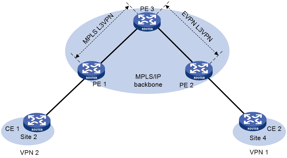
As shown in Figure 3, when you configure an L3VPN network to convey EVPN service, perform the following tasks on PE 3 to enable communication between EVPN L3VPN and MPLS L3VPN:
· Enable BGP VPNv4 or VPNv6 route advertisement for the BGP EVPN address family.
· Enable BGP EVPN route advertisement for the BGP VPNv4 or VPNv6 address family.
Figure 3 Communication between MPLS L3VPN and EVPN L3VPN
Enabling BGP VPNv4 or VPNv6 route advertisement for the BGP EVPN address family
1. Enter system view.
system-view
2. Enter BGP instance view.
bgp as-number [ instance instance-name ]
3. Enter BGP EVPN address family view.
address-family l2vpn evpn
4. Enable BGP VPNv4 or VPNv6 route advertisement for the BGP EVPN address family.
advertise l3vpn route [ replace-rt ][ advertise-policy policy-name ]
By default, BGP VPNv4 or VPNv6 routes are not advertised through the BGP EVPN address family.
Enabling BGP EVPN route advertisement for the BGP VPNv4 or VPNv6 address family
1. Enter system view.
system-view
2. Enter BGP instance view.
bgp as-number [ instance instance-name ]
3. Enter BGP VPNv4 address family view or BGP VPNv6 address family view.
address-family { vpnv4 | vpnv6 }
4. Enable BGP EVPN route advertisement for the BGP VPNv4 or VPNv6 address family.
advertise evpn route [ replace-rt ][ advertise-policy policy-name ]
By default, BGP EVPN routes are not advertised through the BGP VPNv4 or VPNv6 address family.
After you execute this command, the device advertises IP prefix advertisement routes and MAC/IP advertisement routes that contain host route information through the BGP VPNv4 or VPNv6 address family.
Configuring BGP EVPN FRR
About this task
BGP EVPN FRR enables the device to calculate backup routes for all routes of the BGP EVPN address family to reduce the traffic interruption caused by link or device failures on the MPLS or IP backbone. If the device learns two unequal-cost routes destined for the same network from different peers, the optimal route is backed up by the other route. When the optimal route becomes unavailable, the device uses the backup route to forward traffic. At the same time, the device calculates a new optimal route and then uses it to direct traffic forwarding.
Restrictions and guidelines
This feature might cause routing loops in certain conditions. Make sure you are fully aware of this feature when you use it on a live network.
Procedure
1. Enter system view.
system-view
2. Enter BGP instance view.
bgp as-number [ instance instance-name ]
3. Enter BGP EVPN address family view.
address-family l2vpn evpn
4. Enable BGP EVPN FRR.
pic
By default, BGP EVPN FRR is disabled.
For more information about this command, see BGP commands in Layer 3—IP Routing Command Reference.
Enabling the VPN Prefix ORF feature
About VPN Prefix ORF
VPN Prefix ORF introduction
By default, in large-scale networks with route reflectors, the BGP EVPN routes reflected by the RR usually include the VPN routes from all BGP-VPN instances on the route originator. The current route limit measures can take effect only on address families. When the number of routes for RR reflection reaches the limit, unwanted BGP-VPN instance routes might occupy most of the receiving end's received routes, resulting in the receiving end not being able to receive the necessary BGP-VPN instance routes.
To resolve this issue, it is required to allow the RR to filter routes based on the BGP-VPN instances of the routes on the originator, implementing router filtering at the granularity of BGP-VPN instances in the BGP VPNv4 address families. Enabling the VPN Prefix Outbound Route Filtering (ORF) feature can resolve the above issue. This feature uses route-refresh messages to send VPN Prefix ORF entries (which contain information for route matching) to peers. Peers will withdraw all previously advertised routes that match the VPN Prefix ORF entries and when sending new routes to the local device, they must filter the routes using both the routing policy on the peer device and the received VPN Prefix ORF entries. Only routes that pass both filters will be sent to the local device. VPN Prefix ORF realizes the advertisement and reception of route control at the BGP-VPN instance granularity. It limits the number of routes at the source of route sending to reduce route exchanges between BGP peers and save network resources.
VPN Prefix ORF operating mechanism
After configuring this feature, the BGP session between the local device and the specified peer/peer group will be disconnected and reestablished for VPN Prefix ORF capability negotiation via Open messages. Negotiation can be successful only if the peer capability-advertise orf vpn-prefix command is configured on both ends of the BGP session. After successful negotiation, the device will be able to parse the route-refresh messages carrying VPN Prefix ORF entries sent by the remote end. A VPN Prefix ORF entry contains a <RD value, source device address> tuple.
|
|
NOTE: If the devices in the BGP session do not support the exchange of route-refresh messages, the VPN Prefix ORF entries will not be successfully sent. Configure the peer capability-advertise route-refresh command on both ends of the BGP session to enable the capability of exchanging route-refresh messages. For more information the peer capability-advertise route-refresh command, see BGP commands in Layer 3—IP Routing Command Reference. |
The VPN Prefix ORF feature uses the following conditions to determine whether to trigger sending VPN Prefix ORF entries:
· The <RD, source device address> tuple used to match VPN routes and the alarm threshold for the matching VPN routes, which is used to match VPN routes.
· The maximum number of routes supported by a BGP-VPN instance, which is set by using the route-limit command.
After these conditions are set on the device, when the number of IPv4 or IPv6 unicast routes in a BGP-VPN instance exceeds the route limit, and the percentage of the routes that match the tuple in the BGP-VPN instance exceeds the alarm threshold:
1. The device checks if there are other BGP-VPN instances configured with the same tuple.
¡ If yes, go to step 2.
¡ If not, go to step 3.
2. The device checks if the number of routes in these BGP-VPN instances has exceeded the route limit and if the number of routes matching the tuple has exceeded the alarm threshold.
¡ If yes, go to step 3.
¡ If not, the BGP-VPN instance that contains routes exceeding the route limit will continue to receive routes and repeat step 2.
3. The device sends a route-refresh message with a VPN Prefix ORF entry to the peer/peer group specified by the peer capability-advertise orf vpn-prefix command.
|
|
TIP: Among the BGP-VPN instances configured with the same tuple, if the number of routes matching the tuple in some BGP-VPN instances has exceeded the alarm threshold, while some BGP-VPN instances have not received any routes matching the tuple, it indicates that these instances cannot receive routes matching the tuple. The device will not consider these BGP-VPN instances when determining whether to trigger sending VPN Prefix ORF entries. |
A VPN Prefix ORF entry contains a <RD value, source device address> tuple. The values of RD and source device address are those specified by using the vpn-prefix-quota command.
After receiving a route-refresh message carrying a VPN Prefix ORF entry from the local device, the specified peer/peer group operates as follows:
· Withdraws all BGP EVPN routes that match both the RD and source device address in the VPN Prefix ORF entry. (The route information matching the source device address in the VPN Prefix ORF entry is the next hop attribute of the route.)
· No longer sends BGP EVPN routes that match the VPN Prefix ORF entry to the local device.
If the device has previously advertised VPN Prefix ORF entries, the entries will remain effective on the peer to filter route advertisement. You can execute the clear bgp vpn-prefix-orf command to withdraw the previously advertised VPN Prefix ORF entries, so that the peer can re-advertise routes that were withdrawn or filtered due to the VPN Prefix ORF entries.
VPN Prefix ORF application network diagram
As shown in Figure 4, VPN instances are configured on each PE. The RR reflects routes from PE 1, PE 2, and PE 3 within the same AS. Both PE 1 and PE 2 have successfully negotiated the VPN Prefix ORF capabilities with the RR. PE 1 specifies the tuple as <RD31, PE3> and the alarm threshold as 70% in the BGP-VPN instances corresponding to VPN1 and VPN2 by using the vpn-prefix-quota command. PE 2 specifies the tuple as <RD31, PE3> and the alarm threshold as 70% in the BGP-VPN instance corresponding to VPN1 by using the vpn-prefix-quota command.
Figure 4 VPN Prefix ORF application network diagram
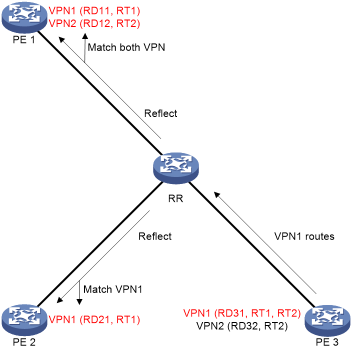
PE 3 advertises routes of VPN1 through BGP EVPN. When the advertised routes cause BGP-VPN instances on PE 1 and PE 2 to exceed the route limit, VPN Prefix ORF will function on PE 1 and PE 2 as follows:
· On PE 1
The number of routes in the BGP-VPN instance for VPN1 exceeded the limit, and the number of routes matching <RD31, PE3> exceeded 70% of the total routes. However, PE 1 would not send route-refresh messages carrying VPN Prefix ORF entries because the BGP-VPN instances for VPN2 and VPN1 have the same tuple <RD31, PE3>, and PE 1 could still receive VPN1 routes carrying RT 1 and RT 2 from PE 3 for the BGP-VPN instance corresponding to VPN2. PE 1 will send a route-refresh message carrying a VPN Prefix ORF entry to the RR only when both the BGP-VPN instances for VPN1 and VPN2 have exceeded the route limit and the VPN routes matching the <RD31, PE3> tuple have also exceeded the alarm threshold. The advertised VPN Prefix ORF entry contains the following information: <RD31, min (maximum route count supported by BGP-VPN instance for VPN1, maximum route count supported by BGP-VPN instance for VPN2), PE3 address>.
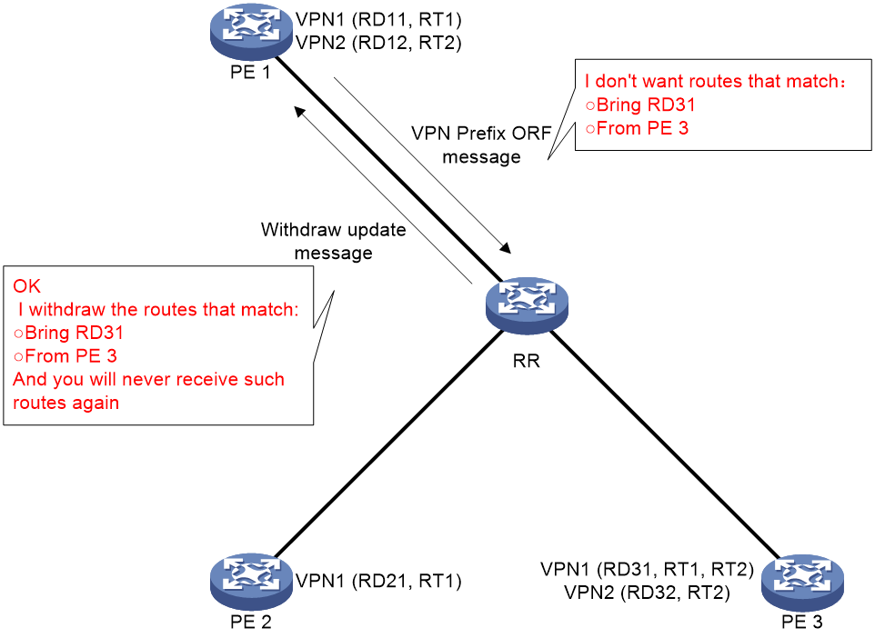
After receiving the route-refresh message with the VPN Prefix ORF entry, the RR will withdraw the advertised routes that meet the following conditions from PE 1 and will no longer advertise the routes that meet the following conditions to PE 1:
¡ The RD carried by the routes is RD31.
¡ The next hop address of the routes is the address of PE 3.
Figure 5 VPN Prefix ORF taking effect
· On PE 2
When the number of routes in the BGP-VPN instance for VPN1 exceeds the limit, PE 2 will immediately send a route-refresh message carrying a VPN Prefix ORF entry to the RR because no other BGP-VPN instances have specified the same tuple. The advertised VPN Prefix ORF entry contains the following information: <RD31, maximum route count supported by BGP-VPN instance for VPN1, PE3 address>.
After receiving the route-refresh message carrying the VPN Prefix ORF entry, the RR will withdraw the advertised routes that meet the following conditions from PE 2 and will no longer advertise routes that meet the following conditions to PE 2:
¡ The RD carried by the routes is RD31.
¡ The next hop address of the routes is the address of PE 3.
Restrictions and guidelines
In the current software version, only VPN Prefix ORF within the same AS is supported. VPN Prefix ORF across ASs is not supported.
You must configure the route-limit, vpn-prefix-quota route-distinguisher, and peer capability-advertise orf vpn-prefix commands at the same time for VPN Prefix ORF to operate properly.
The receiving end of VPN Prefix ORF information does not differentiate between IPv4 and IPv6 routes in withdrawing BGP EVPN routes, no matter whether the VPN Prefix ORF information is triggered by either IPv4 private network routes or IPv6 private network routes. All BGP EVPN routes matching the VPN Prefix ORF information will be withdrawn.
Procedure
Configuring a VPN instance
1. Enter system view.
system-view
2. Create a VPN instance and enter its view.
ip vpn-instance vpn-instance-name
For more information about this command, see MPLS L3VPN commands in MPLS Command Reference.
3. Configure an RD for the VPN instance.
route-distinguisher route-distinguisher
By default, no RD is configured for a VPN instance.
For more information about this command, see MPLS L3VPN commands in MPLS Command Reference.
4. Configure route targets for the VPN instance.
vpn-target vpn-target&<1-8> [ both | export-extcommunity | import-extcommunity ]
By default, no route targets are configured for a VPN instance.
For more information about this command, see MPLS L3VPN commands in MPLS Command Reference.
Configuring the conditions that trigger the VPN Prefix ORF mechanism
1. Enter system view.
system-view
2. Enter BGP instance view.
bgp as-number [ instance instance-name ]
For more information about this command, see BGP commands in Layer 3—IP Routing Command Reference.
3. Enter BGP-VPN instance view.
ip vpn-instance vpn-instance-name
For more information about this command, see BGP commands in Layer 3—IP Routing Command Reference.
4. Enter BGP-VPN IPv4 unicast address family view or BGP-VPN IPv6 unicast address family view.
¡ Enter BGP-VPN IPv4 unicast address family view.
address-family ipv4 [ unicast ]
¡ Enter BGP-VPN IPv6 unicast address family view.
address-family ipv6 [ unicast ]
For more information about these commands, see BGP commands in Layer 3—IP Routing Command Reference.
5. Set the maximum number of routes supported by the BGP-VPN instance.
route-limit limit
By default, the maximum number of routes supported by a BGP-VPN instance is 4294967295.
For more information about this command, see MPLS L3VPN commands in MPLS Command Reference.
6. Set the tuple for routing matching and set the alarm threshold for routes matching the tuple.
vpn-prefix-quota route-distinguisher route-distinguisher source-address { ipv4-address | ipv6-address } quota threshold evpn
By default, no tuple or alarm threshold is set, and no alarm information will be triggered for tuple-matching routes.
For more information about this command, see MPLS L3VPN commands in MPLS Command Reference.
Configuring the VPN Prefix ORF feature
1. Enter system view.
system-view
2. Enter BGP instance view.
bgp as-number [ instance instance-name ]
3. Enter BGP EVPN address family view.
address-family l2vpn evpn
4. Enable negotiating VPN Prefix ORF capabilities with the specified BGP peer or peer group.
peer { group-name | ipv4-address [ mask-length ] |ipv6-address [ prefix-length ] } capability-advertise orf vpn-prefix { both | send | receive }
By default, the local end does not negotiate VPN Prefix ORF capabilities with BGP peer/peer group.
For more information about this command, see MPLS L3VPN commands in MPLS Command Reference.
5. (Optional.) Withdraw the advertised VPN Prefix ORF entries.
a. Execute the following commands in sequence to return to user view:
quit
quit
quit
b. Withdraw the advertised VPN Prefix ORF entries.
clear bgp [ instance instance-name ] vpn-prefix-orf [ vpn-instance vpn-instance-name | route-distinguisher route-distinguisher source-address { ipv4-address | ipv6-address } ] evpn
For more information about this command, see MPLS L3VPN commands in MPLS Command Reference.
Display and maintenance commands for EVPN L3VPN
Execute display commands in any view.
|
Task |
Command |
|
Display incoming labels for IP prefix advertisement routes. |
display bgp [ instance instance-name ] l2vpn evpn inlabel |
|
Display BGP VPNv4 peer group information. |
display bgp [ instance instance-name ] group vpnv4 [ vpn-instance vpn-instance-name ] [ group-name group-name ] |
|
Display BGP VPNv6 peer group information. |
display bgp [ instance instance-name ] group vpnv6 [ group-name group-name ] |
|
Display BGP VPNv4 peer information. |
display bgp [ instance instance-name ] peer vpnv4 [ vpn-instance vpn-instance-name ] [ ipv4-address mask-length | { ipv4-address | group-name group-name } log-info | [ ipv4-address ] verbose ] |
|
Display BGP VPNv6 peer information. |
display bgp [ instance instance-name ] peer vpnv6 [ ipv4-address mask-length | { ipv4-address | group-name group-name } log-info | [ ipv4-address ] verbose ] |
|
Display BGP VPNv4 routes. |
display bgp [ instance instance-name ] routing-table vpnv4 [ [ route-distinguisher route-distinguisher ] [ ipv4-address [ { mask-length | mask } [ longest-match ] ] | ipv4-address [ mask-length | mask ] advertise-info | as-path-acl as-path-acl-number | community-list { { basic-community-list-number | comm-list-name } [ whole-match ] | adv-community-list-number } ] | [ vpn-instance vpn-instance-name ] peer ipv4-address { advertised-routes | received-routes } [ ipv4-address [ mask-length | mask ] | statistics ] | statistics ] |
|
Display BGP VPNv6 routes. |
display bgp [ instance instance-name ] routing-table vpnv6 [ [ route-distinguisher route-distinguisher ] [ ipv6-address prefix-length [ advertise-info ] | as-path-acl as-path-acl-number | community-list { { basic-community-list-number | comm-list-name } [ whole-match ] | adv-community-list-number } ] | peer ipv4-address { advertised-routes | received-routes } [ ipv6-address prefix-length | statistics ] | statistics ] |
|
Display routing table information for a VPN instance. |
display ip routing-table vpn-instance vpn-instance-name [ statistics | verbose ] |
|
Display information about VPN instances. |
display ip vpn-instance [ instance-name vpn-instance-name ] |
|
|
NOTE: For more information about the display ip routing-table vpn-instance command, see IP routing basics commands in Layer 3—IP Routing Command Reference. |
|
|
NOTE: For more information about the following commands, see MPLS L3VPN commands in MPLS Command Reference: · display bgp group vpnv4. · display bgp peer vpnv4. · display bgp routing-table vpnv4. · display ip vpn-instance |
EVPN L3VPN configuration examples
Example: Configuring IPv4 EVPN L3VPN
Network configuration
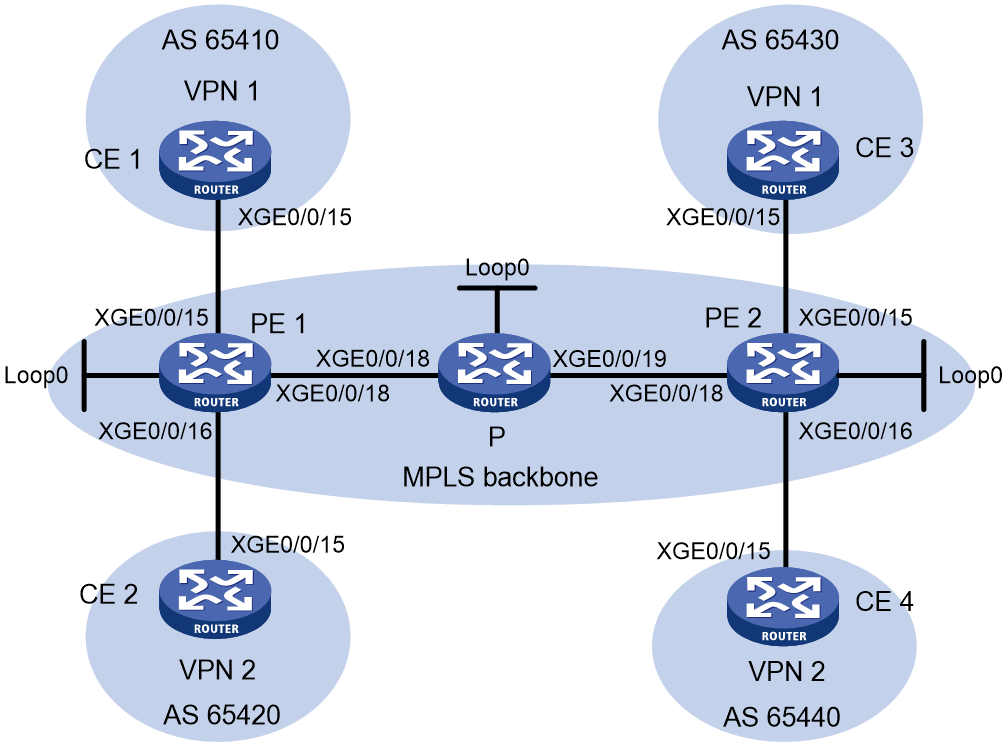
As shown in Figure 6:
· Configure IPv4 EVPN L3VPN for different sites of a VPN instance to communicate with each other.
· Configure route target 111:1 for VPN 1 and route target 222:2 for VPN 2 to isolate these VPN instances.
· Configure the CE and the PE of each site to use EBGP to exchange VPN routes.
· Configure the PEs to communicate through OSPF and to exchange BGP EVPN routes through MP-IBGP.
|
Device |
Interface |
IP address |
Device |
Interface |
IP address |
|
CE 1 |
XGE0/0/15 |
10.1.1.1/24 |
P |
Loop0 |
2.2.2.9/32 |
|
PE 1 |
Loop0 |
1.1.1.9/32 |
|
XGE0/0/18 |
172.1.1.2/24 |
|
|
XGE0/0/15 |
10.1.1.2/24 |
|
XGE0/0/19 |
172.2.1.1/24 |
|
|
XGE0/0/16 |
10.2.1.2/24 |
PE 2 |
Loop0 |
3.3.3.9/32 |
|
|
XGE0/0/18 |
172.1.1.1/24 |
|
XGE0/0/15 |
10.3.1.2/24 |
|
CE 2 |
XGE0/0/15 |
10.2.1.1/24 |
|
XGE0/0/16 |
10.4.1.2/24 |
|
CE 3 |
XGE0/0/15 |
10.3.1.1/24 |
|
XGE0/0/18 |
172.2.1.2/24 |
|
CE 4 |
XGE0/0/15 |
10.4.1.1/24 |
|
|
|
Procedure
1. Configure an IGP on the MPLS backbone for the PEs and P device to reach one another:
# Configure PE 1.
<PE1> system-view
[PE1] interface loopback 0
[PE1-LoopBack0] ip address 1.1.1.9 32
[PE1-LoopBack0] quit
[PE1] interface ten-gigabitethernet 0/0/18
[PE1-Ten-GigabitEthernet0/0/18] ip address 172.1.1.1 24
[PE1-Ten-GigabitEthernet0/0/18] quit
[PE1] ospf
[PE1-ospf-1] area 0
[PE1-ospf-1-area-0.0.0.0] network 172.1.1.0 0.0.0.255
[PE1-ospf-1-area-0.0.0.0] network 1.1.1.9 0.0.0.0
[PE1-ospf-1-area-0.0.0.0] quit
[PE1-ospf-1] quit
# Configure the P device.
<P> system-view
[P] interface loopback 0
[P-LoopBack0] ip address 2.2.2.9 32
[P-LoopBack0] quit
[P] interface ten-gigabitethernet 0/0/18
[P-Ten-GigabitEthernet0/0/18] ip address 172.1.1.2 24
[P-Ten-GigabitEthernet0/0/18] quit
[P] interface ten-gigabitethernet 0/0/19
[P-Ten-GigabitEthernet0/0/19] ip address 172.2.1.1 24
[P-Ten-GigabitEthernet0/0/19] quit
[P] ospf
[P-ospf-1] area 0
[P-ospf-1-area-0.0.0.0] network 172.1.1.0 0.0.0.255
[P-ospf-1-area-0.0.0.0] network 172.2.1.0 0.0.0.255
[P-ospf-1-area-0.0.0.0] network 2.2.2.9 0.0.0.0
[P-ospf-1-area-0.0.0.0] quit
[P-ospf-1] quit
# Configure PE 2.
<PE2> system-view
[PE2] interface loopback 0
[PE2-LoopBack0] ip address 3.3.3.9 32
[PE2-LoopBack0] quit
[PE2] interface ten-gigabitethernet 0/0/18
[PE2-Ten-GigabitEthernet0/0/18] ip address 172.2.1.2 24
[PE2-Ten-GigabitEthernet0/0/18] quit
[PE2] ospf
[PE2-ospf-1] area 0
[PE2-ospf-1-area-0.0.0.0] network 172.2.1.0 0.0.0.255
[PE2-ospf-1-area-0.0.0.0] network 3.3.3.9 0.0.0.0
[PE2-ospf-1-area-0.0.0.0] quit
[PE2-ospf-1] quit
# Execute the display ospf peer command to verify that OSPF adjacencies in Full state have been established between PE 1, P, and PE 2. Execute the display ip routing-table command to verify that the PEs have learned the routes to the loopback interfaces of each other. (Details not shown.)
2. Configure basic MPLS and MPLS LDP on the MPLS backbone to establish LDP LSPs:
# Configure PE 1.
[PE1] mpls lsr-id 1.1.1.9
[PE1] mpls ldp
[PE1-ldp] quit
[PE1] interface ten-gigabitethernet 0/0/18
[PE1-Ten-GigabitEthernet0/0/18] mpls enable
[PE1-Ten-GigabitEthernet0/0/18] mpls ldp enable
[PE1-Ten-GigabitEthernet0/0/18] quit
# Configure the P device.
[P] mpls lsr-id 2.2.2.9
[P] mpls ldp
[P-ldp] quit
[P] interface ten-gigabitethernet 0/0/18
[P-Ten-GigabitEthernet0/0/18] mpls enable
[P-Ten-GigabitEthernet0/0/18] mpls ldp enable
[P-Ten-GigabitEthernet0/0/18] quit
[P] interface ten-gigabitethernet 0/0/19
[P-Ten-GigabitEthernet0/0/19] mpls enable
[P-Ten-GigabitEthernet0/0/19] mpls ldp enable
[P-Ten-GigabitEthernet0/0/19] quit
# Configure PE 2.
[PE2] mpls lsr-id 3.3.3.9
[PE2] mpls ldp
[PE2-ldp] quit
[PE2] interface ten-gigabitethernet 0/0/18
[PE2-Ten-GigabitEthernet0/0/18] mpls enable
[PE2-Ten-GigabitEthernet0/0/18] mpls ldp enable
[PE2-Ten-GigabitEthernet0/0/18] quit
# Execute the display mpls ldp peer command to verify that LDP sessions in Operational state have been established between PE 1, P, and PE 2. Execute the display mpls ldp lsp command to verify that the LSPs have been established by LDP. (Details not shown.)
3. Configure VPN instances on PEs to allow CE access:
# Configure PE 1.
[PE1] ip vpn-instance vpn1
[PE1-vpn-instance-vpn1] route-distinguisher 100:1
[PE1-vpn-instance-vpn1] vpn-target 111:1
[PE1-vpn-instance-vpn1] quit
[PE1] ip vpn-instance vpn2
[PE1-vpn-instance-vpn2] route-distinguisher 100:2
[PE1-vpn-instance-vpn2] vpn-target 222:2
[PE1-vpn-instance-vpn2] quit
[PE1] interface ten-gigabitethernet 0/0/15
[PE1-Ten-GigabitEthernet0/0/15] ip binding vpn-instance vpn1
[PE1-Ten-GigabitEthernet0/0/15] ip address 10.1.1.2 24
[PE1-Ten-GigabitEthernet0/0/15] quit
[PE1] interface ten-gigabitethernet 0/0/16
[PE1-Ten-GigabitEthernet0/0/16] ip binding vpn-instance vpn2
[PE1-Ten-GigabitEthernet0/0/16] ip address 10.2.1.2 24
[PE1-Ten-GigabitEthernet0/0/16] quit
# Configure PE 2.
[PE2] ip vpn-instance vpn1
[PE2-vpn-instance-vpn1] route-distinguisher 200:1
[PE2-vpn-instance-vpn1] vpn-target 111:1
[PE2-vpn-instance-vpn1] quit
[PE2] ip vpn-instance vpn2
[PE2-vpn-instance-vpn2] route-distinguisher 200:2
[PE2-vpn-instance-vpn2] vpn-target 222:2
[PE2-vpn-instance-vpn2] quit
[PE2] interface ten-gigabitethernet 0/0/15
[PE2-Ten-GigabitEthernet0/0/15] ip binding vpn-instance vpn1
[PE2-Ten-GigabitEthernet0/0/15] ip address 10.3.1.2 24
[PE2-Ten-GigabitEthernet0/0/15] quit
[PE2] interface ten-gigabitethernet 0/0/16
[PE2-Ten-GigabitEthernet0/0/16] ip binding vpn-instance vpn2
[PE2-Ten-GigabitEthernet0/0/16] ip address 10.4.1.2 24
[PE2-Ten-GigabitEthernet0/0/16] quit
# Configure IP addresses for the CEs according to Figure 6. (Details not shown.)
# Execute the display ip vpn-instance command on the PEs to display the configuration of the VPN instance, for example, on PE 1.
[PE1] display ip vpn-instance
Total VPN-Instances configured : 2
Total IPv4 VPN-Instances configured : 0
Total IPv6 VPN-Instances configured : 0
Total IPv4 VPN-Instances EVPN configured : 0
Total IPv6 VPN-Instances EVPN configured : 0
VPN-Instance Name RD Address family Create time
vpn1 100:1 N/A 2018/12/13 12:49:08
vpn2 100:2 N/A 2018/12/13 12:49:20
# Use the ping command on the PEs to verify that the PEs can ping their attached CEs, for example, on PE 1.
[PE1] ping -vpn-instance vpn1 10.1.1.1
Ping 10.1.1.1 (10.1.1.1): 56 data bytes, press CTRL_C to break
56 bytes from 10.1.1.1: icmp_seq=0 ttl=255 time=1.000 ms
56 bytes from 10.1.1.1: icmp_seq=1 ttl=255 time=2.000 ms
56 bytes from 10.1.1.1: icmp_seq=2 ttl=255 time=0.000 ms
56 bytes from 10.1.1.1: icmp_seq=3 ttl=255 time=1.000 ms
56 bytes from 10.1.1.1: icmp_seq=4 ttl=255 time=0.000 ms
--- Ping statistics for 10.1.1.1 in VPN instance vpn1 ---
5 packet(s) transmitted, 5 packet(s) received, 0.0% packet loss
round-trip min/avg/max/std-dev = 0.000/0.800/2.000/0.748 ms
4. Establish EBGP peer relationships between PEs and CEs, and redistribute VPN routes into BGP:
# Configure CE 1.
<CE1> system-view
[CE1] bgp 65410
[CE1-bgp-default] peer 10.1.1.2 as-number 100
[CE1-bgp-default] address-family ipv4 unicast
[CE1-bgp-default-ipv4] peer 10.1.1.2 enable
[CE1-bgp-default-ipv4] import-route direct
[CE1-bgp-default-ipv4] quit
[CE1-bgp-default] quit
# Configure the other three CEs in the same way that CE 1 is configured. (Details not shown.)
# Configure PE 1.
[PE1] bgp 100
[PE1-bgp-default] ip vpn-instance vpn1
[PE1-bgp-default-vpn1] peer 10.1.1.1 as-number 65410
[PE1-bgp-default-vpn1] address-family ipv4 unicast
[PE1-bgp-default-ipv4-vpn1] peer 10.1.1.1 enable
[PE1-bgp-default-ipv4-vpn1] quit
[PE1-bgp-default-vpn1] quit
[PE1-bgp-default] ip vpn-instance vpn2
[PE1-bgp-default-vpn2] peer 10.2.1.1 as-number 65420
[PE1-bgp-default-vpn2] address-family ipv4 unicast
[PE1-bgp-default-ipv4-vpn2] peer 10.2.1.1 enable
[PE1-bgp-default-ipv4-vpn2] quit
[PE1-bgp-default-vpn1] quit
[PE1-bgp-default] quit
# Configure PE 2 in the same way that PE 1 is configured. (Details not shown.)
# Execute the display bgp peer ipv4 vpn-instance command on the PEs to verify that a BGP peer relationship in Established state has been established between a PE and a CE. (Details not shown.)
5. Create an MP-IBGP peer relationship between PEs:
# Configure PE 1.
[PE1] bgp 100
[PE1-bgp-default] peer 3.3.3.9 as-number 100
[PE1-bgp-default] peer 3.3.3.9 connect-interface loopback 0
[PE1-bgp-default] address-family l2vpn evpn
[PE1-bgp-default-evpn] peer 3.3.3.9 enable
[PE1-bgp-default-evpn] quit
[PE1-bgp-default] quit
# Configure PE 2.
[PE2] bgp 100
[PE2-bgp-default] peer 1.1.1.9 as-number 100
[PE2-bgp-default] peer 1.1.1.9 connect-interface loopback 0
[PE2-bgp-default] address-family l2vpn evpn
[PE2-bgp-default-evpn] peer 1.1.1.9 enable
[PE2-bgp-default-evpn] quit
[PE2-bgp-default] quit
# Execute the display bgp peer l2vpn evpn command on the PEs to verify that a BGP peer relationship in Established state has been established between the PEs. (Details not shown.)
6. Enable EVPN to advertise VPN routes on the PEs:
# Configure PE 1.
[PE1] ip vpn-instance vpn1
[PE1-vpn-instance-vpn1] address-family ipv4
[PE1-vpn-ipv4-vpn1] evpn mpls routing-enable
[PE1-vpn-ipv4-vpn1] quit
[PE1-vpn-instance-vpn1] quit
[PE1] ip vpn-instance vpn2
[PE1-vpn-instance-vpn2] address-family ipv4
[PE1-vpn-ipv4-vpn2] evpn mpls routing-enable
[PE1-vpn-ipv4-vpn2] quit
[PE1-vpn-instance-vpn2] quit
# Configure PE 2.
[PE2] ip vpn-instance vpn1
[PE2-vpn-instance-vpn1] address-family ipv4
[PE2-vpn-ipv4-vpn1] evpn mpls routing-enable
[PE2-vpn-ipv4-vpn1] quit
[PE2-vpn-instance-vpn1] quit
[PE2] ip vpn-instance vpn2
[PE2-vpn-instance-vpn2] address-family ipv4
[PE2-vpn-ipv4-vpn2] evpn mpls routing-enable
[PE2-vpn-ipv4-vpn2] quit
[PE2-vpn-instance-vpn2] quit
# Execute the display bgp l2vpn evpn command on the PEs to verify that the VPN routes received from CEs have been added to the EVPN routing table. (Details not shown.)
7. Enable MPLS encapsulation for the IP prefix advertisement routes on the PEs:
# Configure PE 1.
[PE1] bgp 100
[PE1-bgp-default] address-family l2vpn evpn
[PE1-bgp-default-evpn] peer 3.3.3.9 advertise encap-type mpls
[PE1-bgp-default-evpn] peer 3.3.3.9 next-hop-local
[PE1-bgp-default-evpn] quit
[PE1-bgp-default] quit
# Configure PE 2.
[PE2] bgp 100
[PE2-bgp-default] address-family l2vpn evpn
[PE2-bgp-default-evpn] peer 1.1.1.9 advertise encap-type mpls
[PE2-bgp-default-evpn] peer 1.1.1.9 next-hop-local
[PE2-bgp-default-evpn] quit
[PE2-bgp-default] quit
# Execute the display bgp l2vpn evpn command to verify that the PEs have received IP prefix advertisement routes from one another.
Verifying the configuration
# Verify that a PE has the route to the remote CE in the same VPN instance, for example, PE 1.
[PE1] display ip routing-table vpn-instance vpn1
Destinations : 11 Routes : 11
Destination/Mask Proto Pre Cost NextHop Interface
0.0.0.0/32 Direct 0 0 127.0.0.1 InLoop0
10.1.1.0/24 Direct 0 0 10.1.1.2 XGE0/0/15
10.1.1.0/32 Direct 0 0 10.1.1.2 XGE0/0/15
10.1.1.2/32 Direct 0 0 127.0.0.1 InLoop0
10.1.1.255/32 Direct 0 0 10.1.1.2 XGE0/0/15
10.3.1.0/24 BGP 255 0 3.3.3.9 XGE0/0/18
127.0.0.0/8 Direct 0 0 127.0.0.1 InLoop0
127.0.0.0/32 Direct 0 0 127.0.0.1 InLoop0
127.0.0.1/32 Direct 0 0 127.0.0.1 InLoop0
127.255.255.255/32 Direct 0 0 127.0.0.1 InLoop0
255.255.255.255/32 Direct 0 0 127.0.0.1 InLoop0
# Verify that CEs of the same VPN can ping each other, and CEs of different VPNs cannot. For example, CE 1 can ping CE 3 (10.3.1.1), but it cannot ping CE 4 (10.4.1.1). (Details not shown.)
Example: Configuring IPv6 EVPN L3VPN
Network configuration
As shown in Figure 7:
· Configure IPv6 EVPN L3VPN for different sites of a VPN instance to communicate with each other.
· Configure route target 111:1 for VPN 1 and route target 222:2 for VPN 2 to isolate these VPN instances.
· Configure the CE and the PE of each site to use EBGP to exchange VPN routes.
· Configure the PEs to communicate through OSPF and to exchange BGP EVPN routes through MP-IBGP.

|
Device |
Interface |
IP address |
Device |
Interface |
IP address |
|
CE 1 |
XGE0/0/15 |
2001:1::1/96 |
P |
Loop0 |
2.2.2.9/32 |
|
PE 1 |
Loop0 |
1.1.1.9/32 |
|
XGE0/0/18 |
172.1.1.2/24 |
|
|
XGE0/0/15 |
2001:1::2/96 |
|
XGE0/0/19 |
172.2.1.1/24 |
|
|
XGE0/0/16 |
2001:2::2/96 |
PE 2 |
Loop0 |
3.3.3.9/32 |
|
|
XGE0/0/18 |
172.1.1.1/24 |
|
XGE0/0/15 |
2001:3::2/96 |
|
CE 2 |
XGE0/0/15 |
2001:2::1/96 |
|
XGE0/0/16 |
2001:4::2/96 |
|
CE 3 |
XGE0/0/15 |
2001:3::1/96 |
|
XGE0/0/18 |
172.2.1.2/24 |
|
CE 4 |
XGE0/0/15 |
2001:4::1/96 |
|
|
|
Procedure
1. Configure an IGP on the MPLS backbone for the PEs and P device to reach one another:
# Configure PE 1.
<PE1> system-view
[PE1] interface loopback 0
[PE1-LoopBack0] ip address 1.1.1.9 32
[PE1-LoopBack0] quit
[PE1] interface ten-gigabitethernet 0/0/18
[PE1-Ten-GigabitEthernet0/0/18] ip address 172.1.1.1 24
[PE1-Ten-GigabitEthernet0/0/18] quit
[PE1] ospf
[PE1-ospf-1] area 0
[PE1-ospf-1-area-0.0.0.0] network 172.1.1.0 0.0.0.255
[PE1-ospf-1-area-0.0.0.0] network 1.1.1.9 0.0.0.0
[PE1-ospf-1-area-0.0.0.0] quit
[PE1-ospf-1] quit
# Configure the P device.
<P> system-view
[P] interface loopback 0
[P-LoopBack0] ip address 2.2.2.9 32
[P-LoopBack0] quit
[P] interface ten-gigabitethernet 0/0/18
[P-Ten-GigabitEthernet0/0/18] ip address 172.1.1.2 24
[P-Ten-GigabitEthernet0/0/18] quit
[P] interface ten-gigabitethernet 0/0/19
[P-Ten-GigabitEthernet0/0/19] ip address 172.2.1.1 24
[P-Ten-GigabitEthernet0/0/19] quit
[P] ospf
[P-ospf-1] area 0
[P-ospf-1-area-0.0.0.0] network 172.1.1.0 0.0.0.255
[P-ospf-1-area-0.0.0.0] network 172.2.1.0 0.0.0.255
[P-ospf-1-area-0.0.0.0] network 2.2.2.9 0.0.0.0
[P-ospf-1-area-0.0.0.0] quit
[P-ospf-1] quit
# Configure PE 2.
<PE2> system-view
[PE2] interface loopback 0
[PE2-LoopBack0] ip address 3.3.3.9 32
[PE2-LoopBack0] quit
[PE2] interface ten-gigabitethernet 0/0/18
[PE2-Ten-GigabitEthernet0/0/18] ip address 172.2.1.2 24
[PE2-Ten-GigabitEthernet0/0/18] quit
[PE2] ospf
[PE2-ospf-1] area 0
[PE2-ospf-1-area-0.0.0.0] network 172.2.1.0 0.0.0.255
[PE2-ospf-1-area-0.0.0.0] network 3.3.3.9 0.0.0.0
[PE2-ospf-1-area-0.0.0.0] quit
[PE2-ospf-1] quit
# Execute the display ospf peer command to verify that OSPF adjacencies in Full state have been established between PE 1, P, and PE 2. Execute the display ip routing-table command to verify that the PEs have learned the routes to the loopback interfaces of each other. (Details not shown.)
2. Configure basic MPLS and MPLS LDP on the MPLS backbone to establish LDP LSPs:
# Configure PE 1.
[PE1] mpls lsr-id 1.1.1.9
[PE1] mpls ldp
[PE1-ldp] quit
[PE1] interface ten-gigabitethernet 0/0/18
[PE1-Ten-GigabitEthernet0/0/18] mpls enable
[PE1-Ten-GigabitEthernet0/0/18] mpls ldp enable
[PE1-Ten-GigabitEthernet0/0/18] quit
# Configure the P device.
[P] mpls lsr-id 2.2.2.9
[P] mpls ldp
[P-ldp] quit
[P] interface ten-gigabitethernet 0/0/18
[P-Ten-GigabitEthernet0/0/18] mpls enable
[P-Ten-GigabitEthernet0/0/18] mpls ldp enable
[P-Ten-GigabitEthernet0/0/18] quit
[P] interface ten-gigabitethernet 0/0/19
[P-Ten-GigabitEthernet0/0/19] mpls enable
[P-Ten-GigabitEthernet0/0/19] mpls ldp enable
[P-Ten-GigabitEthernet0/0/19] quit
# Configure PE 2.
[PE2] mpls lsr-id 3.3.3.9
[PE2] mpls ldp
[PE2-ldp] quit
[PE2] interface ten-gigabitethernet 0/0/18
[PE2-Ten-GigabitEthernet0/0/18] mpls enable
[PE2-Ten-GigabitEthernet0/0/18] mpls ldp enable
[PE2-Ten-GigabitEthernet0/0/18] quit
# Execute the display mpls ldp peer command to verify that LDP sessions in Operational state have been established between PE 1, P, and PE 2. Execute the display mpls ldp lsp command to verify that the LSPs have been established by LDP. (Details not shown.)
3. Configure VPN instances on PEs to allow CE access:
# Configure PE 1.
[PE1] ip vpn-instance vpn1
[PE1-vpn-instance-vpn1] route-distinguisher 100:1
[PE1-vpn-instance-vpn1] vpn-target 111:1
[PE1-vpn-instance-vpn1] quit
[PE1] ip vpn-instance vpn2
[PE1-vpn-instance-vpn2] route-distinguisher 100:2
[PE1-vpn-instance-vpn2] vpn-target 222:2
[PE1-vpn-instance-vpn2] quit
[PE1] interface ten-gigabitethernet 0/0/15
[PE1-Ten-GigabitEthernet0/0/15] ip binding vpn-instance vpn1
[PE1-Ten-GigabitEthernet0/0/15] ipv6 address 2001:1::2 96
[PE1-Ten-GigabitEthernet0/0/15] quit
[PE1] interface ten-gigabitethernet 0/0/16
[PE1-Ten-GigabitEthernet0/0/16] ip binding vpn-instance vpn2
[PE1-Ten-GigabitEthernet0/0/16] ipv6 address 2001:2::2 96
[PE1-Ten-GigabitEthernet0/0/16] quit
# Configure PE 2.
[PE2] ip vpn-instance vpn1
[PE2-vpn-instance-vpn1] route-distinguisher 200:1
[PE2-vpn-instance-vpn1] vpn-target 111:1
[PE2-vpn-instance-vpn1] quit
[PE2] ip vpn-instance vpn2
[PE2-vpn-instance-vpn2] route-distinguisher 200:2
[PE2-vpn-instance-vpn2] vpn-target 222:2
[PE2-vpn-instance-vpn2] quit
[PE2] interface ten-gigabitethernet 0/0/15
[PE2-Ten-GigabitEthernet0/0/15] ip binding vpn-instance vpn1
[PE2-Ten-GigabitEthernet0/0/15] ipv6 address 2001:3::2 96
[PE2-Ten-GigabitEthernet0/0/15] quit
[PE2] interface ten-gigabitethernet 0/0/16
[PE2-Ten-GigabitEthernet0/0/16] ip binding vpn-instance vpn2
[PE2-Ten-GigabitEthernet0/0/16] ipv6 address 2001:4::2 96
[PE2-Ten-GigabitEthernet0/0/16] quit
# Configure IP addresses for the CEs according to Figure 7. (Details not shown.)
# Execute the display ip vpn-instance command on the PEs to display the configuration of the VPN instance, for example, on PE 1.
[PE1] display ip vpn-instance
Total VPN-Instances configured : 2
Total IPv4 VPN-Instances configured : 0
Total IPv6 VPN-Instances configured : 0
Total IPv4 VPN-Instances EVPN configured : 0
Total IPv6 VPN-Instances EVPN configured : 0
VPN-Instance Name RD Address family Create time
vpn1 100:1 N/A 2018/12/13 12:49:08
vpn2 100:2 N/A 2018/12/13 12:49:20
# Use the ping command on the PEs to verify that the PEs can ping their attached CEs, for example, on PE 1.
[PE1] ping ipv6 -vpn-instance vpn1 2001:1::1
Ping6(56 bytes) 2001:1::2 --> 2001:1::1, press CTRL_C to break
56 bytes from 2001:1::1, icmp_seq=0 hlim=64 time=9.000 ms
56 bytes from 2001:1::1, icmp_seq=1 hlim=64 time=1.000 ms
56 bytes from 2001:1::1, icmp_seq=2 hlim=64 time=0.000 ms
56 bytes from 2001:1::1, icmp_seq=3 hlim=64 time=0.000 ms
56 bytes from 2001:1::1, icmp_seq=4 hlim=64 time=0.000 ms
--- Ping6 statistics for 2001:1::1 ---
5 packet(s) transmitted, 5 packet(s) received, 0.0% packet loss
round-trip min/avg/max/std-dev = 0.000/2.000/9.000/3.521 ms
4. Establish EBGP peer relationships between PEs and CEs, and redistribute VPN routes into BGP:
# Configure CE 1.
<CE1> system-view
[CE1] bgp 65410
[CE1-bgp-default] peer 2001:1::2 as-number 100
[CE1-bgp-default] address-family ipv6 unicast
[CE1-bgp-default-ipv6] peer 2001:1::2 enable
[CE1-bgp-default-ipv6] import-route direct
[CE1-bgp-default-ipv6] quit
[CE1-bgp-default] quit
# Configure the other three CEs in the same way that CE 1 is configured. (Details not shown.)
# Configure PE 1.
[PE1] bgp 100
[PE1-bgp-default] ip vpn-instance vpn1
[PE1-bgp-default-vpn1] peer 2001:1::1 as-number 65410
[PE1-bgp-default-vpn1] address-family ipv6 unicast
[PE1-bgp-default-ipv6-vpn1] peer 2001:1::1 enable
[PE1-bgp-default-ipv6-vpn1] quit
[PE1-bgp-default-vpn1] quit
[PE1-bgp-default] ip vpn-instance vpn2
[PE1-bgp-default-vpn2] peer 2001:2::1 as-number 65420
[PE1-bgp-default-vpn2] address-family ipv6 unicast
[PE1-bgp-default-ipv6-vpn2] peer 2001:2::1 enable
[PE1-bgp-default-ipv6-vpn2] quit
[PE1-bgp-default-vpn2] quit
[PE1-bgp-default] quit
# Configure PE 2 in the same way that PE 1 is configured. (Details not shown.)
# Execute the display bgp peer ipv6 vpn-instance command on the PEs to verify that a BGP peer relationship in Established state has been established between a PE and a CE. (Details not shown.)
5. Create an MP-IBGP peer relationship between PEs:
# Configure PE 1.
[PE1] bgp 100
[PE1-bgp-default] peer 3.3.3.9 as-number 100
[PE1-bgp-default] peer 3.3.3.9 connect-interface loopback 0
[PE1-bgp-default] address-family l2vpn evpn
[PE1-bgp-default-evpn] peer 3.3.3.9 enable
[PE1-bgp-default-evpn] quit
[PE1-bgp-default] quit
# Configure PE 2.
[PE2] bgp 100
[PE2-bgp-default] peer 1.1.1.9 as-number 100
[PE2-bgp-default] peer 1.1.1.9 connect-interface loopback 0
[PE2-bgp-default] address-family l2vpn evpn
[PE2-bgp-default-evpn] peer 1.1.1.9 enable
[PE2-bgp-default-evpn] quit
[PE2-bgp-default] quit
# Execute the display bgp peer l2vpn evpn command on the PEs to verify that a BGP peer relationship in Established state has been established between the PEs. (Details not shown.)
6. Enable EVPN to advertise VPN routes on the PEs:
# Configure PE 1.
[PE1] ip vpn-instance vpn1
[PE1-vpn-instance-vpn1] address-family ipv6
[PE1-vpn-ipv6-vpn1] evpn mpls routing-enable
[PE1-vpn-ipv6-vpn1] quit
[PE1-vpn-instance-vpn1] quit
[PE1] ip vpn-instance vpn2
[PE1-vpn-instance-vpn2] address-family ipv6
[PE1-vpn-ipv6-vpn2] evpn mpls routing-enable
[PE1-vpn-ipv6-vpn2] quit
[PE1-vpn-instance-vpn2] quit
# Configure PE 2.
[PE2] ip vpn-instance vpn1
[PE2-vpn-instance-vpn1] address-family ipv6
[PE2-vpn-ipv6-vpn1] evpn mpls routing-enable
[PE2-vpn-ipv6-vpn1] quit
[PE2-vpn-instance-vpn1] quit
[PE2] ip vpn-instance vpn2
[PE2-vpn-instance-vpn2] address-family ipv6
[PE2-vpn-ipv6-vpn2] evpn mpls routing-enable
[PE2-vpn-ipv6-vpn2] quit
[PE2-vpn-instance-vpn2] quit
# Execute the display bgp l2vpn evpn command on the PEs to verify that the VPN routes received from CEs have been added to the EVPN routing table. (Details not shown.)
7. Enable MPLS encapsulation for the IP prefix advertisement routes on the PEs:
# Configure PE 1.
[PE1] bgp 100
[PE1-bgp-default] address-family l2vpn evpn
[PE1-bgp-default-evpn] peer 3.3.3.9 advertise encap-type mpls
[PE1-bgp-default-evpn] peer 3.3.3.9 next-hop-local
[PE1-bgp-default-evpn] quit
[PE1-bgp-default] quit
# Configure PE 2.
[PE2] bgp 100
[PE2-bgp-default] address-family l2vpn evpn
[PE2-bgp-default-evpn] peer 1.1.1.9 advertise encap-type mpls
[PE2-bgp-default-evpn] peer 1.1.1.9 next-hop-local
[PE2-bgp-default-evpn] quit
[PE2-bgp-default] quit
# Execute the display bgp l2vpn evpn command to verify that the PEs have received IP prefix advertisement routes from one another.
Verifying the configuration
# Verify that a PE has the route to the remote CE in the same VPN instance, for example, PE 1.
[PE1] display ipv6 routing-table vpn-instance vpn1
Destinations : 5 Routes : 5
Destination: ::1/128 Protocol : Direct
NextHop : ::1 Preference: 0
Interface : InLoop0 Cost : 0
Destination: 2001:1::/96 Protocol : Direct
NextHop : :: Preference: 0
Interface : XGE0/0/15 Cost : 0
Destination: 2001:1::2/128 Protocol : Direct
NextHop : ::1 Preference: 0
Interface : InLoop0 Cost : 0
Destination: 2001:3::/96 Protocol : BGP4+
NextHop : ::FFFF:3.3.3.9 Preference: 255
Interface : XGE0/0/18 Cost : 0
Destination: FE80::/10 Protocol : Direct
NextHop : :: Preference: 0
Interface : NULL0 Cost : 0
[PE1] display ipv6 routing-table vpn-instance vpn2
Destinations : 5 Routes : 5
Destination: ::1/128 Protocol : Direct
NextHop : ::1 Preference: 0
Interface : InLoop0 Cost : 0
Destination: 2001:2::/96 Protocol : Direct
NextHop : :: Preference: 0
Interface : XGE0/0/16 Cost : 0
Destination: 2001:2::2/128 Protocol : Direct
NextHop : ::1 Preference: 0
Interface : InLoop0 Cost : 0
Destination: 2001:4::/96 Protocol : BGP4+
NextHop : ::FFFF:3.3.3.9 Preference: 255
Interface : XGE0/0/18 Cost : 0
Destination: FE80::/10 Protocol : Direct
NextHop : :: Preference: 0
Interface : NULL0 Cost : 0
# Verify that CEs of the same VPN can ping each other, and CEs of different VPNs cannot. For example, CE 1 can ping CE 3 (2001:3::1), but it cannot ping CE 4 (2001:4::1). (Details not shown.)
Example: Enabling communication between IPv4 MPLS L3VPN and IPv4 EVPN L3VPN
Network configuration
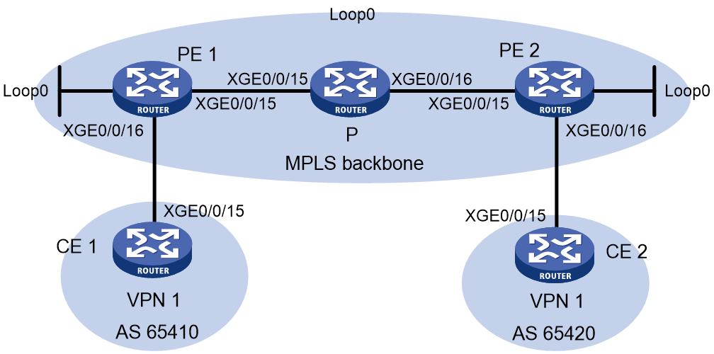
As shown in Figure 8:
· Configure EVPN for CE 1 and CE 2 of VPN 1 to communicate.
· Configure OSPF as the IGP on the MPLS backbone for the P device and PEs to communicate.
· Configure the CEs to exchange VPN routes through EBGP.
· Configure the P device and PE 1 to exchange VPNv4 routes through MP-IBGP, and configure the P device and PE 2 to exchange BGP EVPN routes through MP-IBGP.
· Configure the P device as an RR to reflect routes between the PEs.

|
Device |
Interface |
IP address |
Device |
Interface |
IP address |
|
PE 1 |
Loop0 |
1.1.1.9/32 |
P |
Loop0 |
2.2.2.9/32 |
|
|
XGE0/0/15 |
10.1.1.1/24 |
|
XGE0/0/15 |
10.1.1.2/24 |
|
|
XGE0/0/16 |
172.1.1.2/24 |
|
XGE0/0/16 |
10.2.1.2/24 |
|
PE 2 |
Loop0 |
3.3.3.9/32 |
CE 1 |
XGE0/0/15 |
172.1.1.1/24 |
|
|
XGE0/0/15 |
10.2.1.1/24 |
CE 2 |
XGE0/0/15 |
172.2.1.1/24 |
|
|
XGE0/0/16 |
172.2.1.2/24 |
|
|
|
Procedure
1. Configure an IGP on the MPLS backbone for the PEs and P device to reach one another:
# Configure PE 1.
<PE1> system-view
[PE1] interface loopback 0
[PE1-LoopBack0] ip address 1.1.1.9 32
[PE1-LoopBack0] quit
[PE1] interface ten-gigabitethernet 0/0/15
[PE1-Ten-GigabitEthernet0/0/15] ip address 10.1.1.1 24
[PE1-Ten-GigabitEthernet0/0/15] quit
[PE1] ospf
[PE1-ospf-1] area 0
[PE1-ospf-1-area-0.0.0.0] network 10.1.1.0 0.0.0.255
[PE1-ospf-1-area-0.0.0.0] network 1.1.1.9 0.0.0.0
[PE1-ospf-1-area-0.0.0.0] quit
[PE1-ospf-1] quit
# Configure the P device.
<P> system-view
[P] interface loopback 0
[P-LoopBack0] ip address 2.2.2.9 32
[P-LoopBack0] quit
[P] interface ten-gigabitethernet 0/0/15
[P-Ten-GigabitEthernet0/0/15] ip address 10.1.1.2 24
[P-Ten-GigabitEthernet0/0/15] quit
[P] interface ten-gigabitethernet 0/0/16
[P-Ten-GigabitEthernet0/0/16] ip address 10.2.1.2 24
[P-Ten-GigabitEthernet0/0/16] quit
[P] ospf
[P-ospf-1] area 0
[P-ospf-1-area-0.0.0.0] network 10.1.1.0 0.0.0.255
[P-ospf-1-area-0.0.0.0] network 10.2.1.0 0.0.0.255
[P-ospf-1-area-0.0.0.0] network 2.2.2.9 0.0.0.0
[P-ospf-1-area-0.0.0.0] quit
[P-ospf-1] quit
# Configure PE 2.
<PE2> system-view
[PE2] interface loopback 0
[PE2-LoopBack0] ip address 3.3.3.9 32
[PE2-LoopBack0] quit
[PE2] interface ten-gigabitethernet 0/0/15
[PE2-Ten-GigabitEthernet0/0/15] ip address 10.2.1.1 24
[PE2-Ten-GigabitEthernet0/0/15] quit
[PE2] ospf
[PE2-ospf-1] area 0
[PE2-ospf-1-area-0.0.0.0] network 10.2.1.0 0.0.0.255
[PE2-ospf-1-area-0.0.0.0] network 3.3.3.9 0.0.0.0
[PE2-ospf-1-area-0.0.0.0] quit
[PE2-ospf-1] quit
# Execute the display ospf peer command to verify that OSPF adjacencies in Full state have been established between PE 1, P, and PE 2. Execute the display ip routing-table command to verify that the PEs have learned the routes to the loopback interfaces of each other. (Details not shown.)
2. Configure basic MPLS and MPLS LDP on the MPLS backbone to establish LDP LSPs:
# Configure PE 1.
[PE1] mpls lsr-id 1.1.1.9
[PE1] mpls ldp
[PE1-ldp] quit
[PE1] interface ten-gigabitethernet 0/0/15
[PE1-Ten-GigabitEthernet0/0/15] mpls enable
[PE1-Ten-GigabitEthernet0/0/15] mpls ldp enable
[PE1-Ten-GigabitEthernet0/0/15] quit
# Configure the P device.
[P] mpls lsr-id 2.2.2.9
[P] mpls ldp
[P-ldp] quit
[P] interface ten-gigabitethernet 0/0/15
[P-Ten-GigabitEthernet0/0/15] mpls enable
[P-Ten-GigabitEthernet0/0/15] mpls ldp enable
[P-Ten-GigabitEthernet0/0/15] quit
[P] interface ten-gigabitethernet 0/0/16
[P-Ten-GigabitEthernet0/0/16] mpls enable
[P-Ten-GigabitEthernet0/0/16] mpls ldp enable
[P-Ten-GigabitEthernet0/0/16] quit
# Configure PE 2.
[PE2] mpls lsr-id 3.3.3.9
[PE2] mpls ldp
[PE2-ldp] quit
[PE2] interface ten-gigabitethernet 0/0/15
[PE2-Ten-GigabitEthernet0/0/15] mpls enable
[PE2-Ten-GigabitEthernet0/0/15] mpls ldp enable
[PE2-Ten-GigabitEthernet0/0/15] quit
# Execute the display mpls ldp peer command to verify that LDP sessions in Operational state have been established between PE 1, P, and PE 2. Execute the display mpls ldp lsp command to verify that the LSPs have been established by LDP. (Details not shown.)
3. Configure VPN instances on the PEs to allow CE access, and configure a VPN instance on the P device to allow MPLS L3VPN access and EVPN L3VPN access:
# Configure PE 1.
[PE1] ip vpn-instance vpn1
[PE1-vpn-instance-vpn1] route-distinguisher 100:1
[PE1-vpn-instance-vpn1] vpn-target 111:1
[PE1-vpn-instance-vpn1] quit
[PE1] interface ten-gigabitethernet 0/0/16
[PE1-Ten-GigabitEthernet0/0/16] ip binding vpn-instance vpn1
[PE1-Ten-GigabitEthernet0/0/16] ip address 172.1.1.2 24
[PE1-Ten-GigabitEthernet0/0/16] quit
# Configure the P device.
[P] ip vpn-instance vpn1
[P-vpn-instance-vpn1] route-distinguisher 100:1
[P-vpn-instance-vpn1] vpn-target 111:1
[P-vpn-instance-vpn1] quit
# Configure PE 2.
[PE2] ip vpn-instance vpn1
[PE2-vpn-instance-vpn1] route-distinguisher 200:1
[PE2-vpn-instance-vpn1] vpn-target 111:1
[PE2-vpn-instance-vpn1] quit
[PE2] interface ten-gigabitethernet 0/0/16
[PE2-Ten-GigabitEthernet0/0/16] ip binding vpn-instance vpn1
[PE2-Ten-GigabitEthernet0/0/16] ip address 172.2.1.2 24
[PE2-Ten-GigabitEthernet0/0/16] quit
# Configure IP addresses for the CEs according to Figure 8. (Details not shown.)
# Execute the display ip vpn-instance command on the PEs to display the configuration of the VPN instance, for example, on PE 1.
[PE1] display ip vpn-instance
Total VPN-Instances configured : 1
Total IPv4 VPN-Instances configured : 0
Total IPv6 VPN-Instances configured : 0
Total IPv4 VPN-Instances EVPN configured : 0
Total IPv6 VPN-Instances EVPN configured : 0
VPN-Instance Name RD Address family Create time
vpn1 100:1 N/A 2018/12/13 12:49:08
# Use the ping command on the PEs to verify that the PEs can ping their attached CEs, for example, on PE 1.
[PE1] ping -vpn-instance vpn1 172.1.1.1
Ping 10.1.1.1 (172.1.1.1): 56 data bytes, press CTRL_C to break
56 bytes from 172.1.1.1: icmp_seq=0 ttl=255 time=1.000 ms
56 bytes from 172.1.1.1: icmp_seq=1 ttl=255 time=2.000 ms
56 bytes from 172.1.1.1: icmp_seq=2 ttl=255 time=0.000 ms
56 bytes from 172.1.1.1: icmp_seq=3 ttl=255 time=1.000 ms
56 bytes from 172.1.1.1: icmp_seq=4 ttl=255 time=0.000 ms
--- Ping statistics for 172.1.1.1 in VPN instance vpn1 ---
5 packet(s) transmitted, 5 packet(s) received, 0.0% packet loss
round-trip min/avg/max/std-dev = 0.000/0.800/2.000/0.748 ms
4. Establish EBGP peer relationships between PEs and CEs, and redistribute VPN routes into BGP:
# Configure CE 1.
<CE1> system-view
[CE1] bgp 65410
[CE1-bgp-default] peer 172.1.1.2 as-number 100
[CE1-bgp-default] address-family ipv4 unicast
[CE1-bgp-default-ipv4] peer 172.1.1.2 enable
[CE1-bgp-default-ipv4] import-route direct
[CE1-bgp-default-ipv4] quit
[CE1-bgp-default] quit
# Configure PE 1.
[PE1] bgp 100
[PE1-bgp-default] ip vpn-instance vpn1
[PE1-bgp-default-vpn1] peer 172.1.1.1 as-number 65410
[PE1-bgp-default-vpn1] address-family ipv4 unicast
[PE1-bgp-default-ipv4-vpn1] peer 172.1.1.1 enable
[PE1-bgp-default-ipv4-vpn1] quit
[PE1-bgp-default-vpn1] quit
# Configure CE 2.
<CE2> system-view
[CE2] bgp 65420
[CE2-bgp-default] peer 172.2.1.2 as-number 100
[CE2-bgp-default] address-family ipv4 unicast
[CE2-bgp-default-ipv4] peer 172.2.1.2 enable
[CE2-bgp-default-ipv4] import-route direct
[CE2-bgp-default-ipv4] quit
[CE2-bgp-default] quit
# Configure PE 2.
[PE2] bgp 100
[PE2-bgp-default] ip vpn-instance vpn1
[PE2-bgp-default-vpn1] peer 172.2.1.1 as-number 65420
[PE2-bgp-default-vpn1] address-family ipv4 unicast
[PE2-bgp-default-ipv4-vpn1] peer 172.2.1.1 enable
[PE2-bgp-default-ipv4-vpn1] quit
[PE2-bgp-default-vpn1] quit
# Execute the display bgp peer ipv4 vpn-instance command on the PEs to verify that a BGP peer relationship in Established state has been established between a PE and a CE. (Details not shown.)
5. Configure route exchange between the P device and the PEs, and configure the P device as an RR:
# Configure PE 1.
[PE1] bgp 100
[PE1-bgp-default] peer 2.2.2.9 as-number 100
[PE1-bgp-default] peer 2.2.2.9 connect-interface loopback 0
[PE1-bgp-default] address-family vpnv4
[PE1-bgp-default-vpnv4] peer 2.2.2.9 enable
[PE1-bgp-default-vpnv4] quit
[PE1-bgp-default] quit
# Configure the P device.
[P] bgp 100
[P-bgp-default] peer 1.1.1.9 as-number 100
[P-bgp-default] peer 1.1.1.9 connect-interface loopback 0
[P-bgp-default] peer 3.3.3.9 as-number 100
[P-bgp-default] peer 3.3.3.9 connect-interface loopback 0
[P-bgp-default] address-family vpnv4
[P-bgp-default-vpnv4] undo policy vpn-target
[P-bgp-default-vpnv4] peer 1.1.1.9 enable
[P-bgp-default-vpnv4] peer 1.1.1.9 reflect-client
[P-bgp-default-vpnv4] quit
[P-bgp-default] address-family l2vpn evpn
[P-bgp-default-evpn] undo policy vpn-target
[P-bgp-default-evpn] peer 3.3.3.9 enable
[P-bgp-default-evpn] peer 3.3.3.9 reflect-client
[P-bgp-default-evpn] quit
[P-bgp-default] quit
# Configure PE 2.
[PE2] bgp 100
[PE2-bgp-default] peer 2.2.2.9 as-number 100
[PE2-bgp-default] peer 2.2.2.9 connect-interface loopback 0
[PE2-bgp-default] address-family l2vpn evpn
[PE2-bgp-default-evpn] peer 2.2.2.9 enable
[PE2-bgp-default-evpn] quit
[PE2-bgp-default] quit
# Execute the display bgp peer vpnv4 command on PE 1 to verify that a BGP peer relationship in Established state has been established with the P device. Execute the display bgp peer l2vpn evpn command on PE 2 to verify that a BGP peer relationship in Established state has been established with the P device. (Details not shown.)
6. Enable EVPN to advertise VPN routes on PE 2 and the P device:
# Configure the P device.
[P] ip vpn-instance vpn1
[P-vpn-instance-vpn1] address-family ipv4
[P-vpn-ipv4-vpn1] evpn mpls routing-enable
[P-vpn-ipv4-vpn1] quit
[P-vpn-instance-vpn1] quit
# Configure PE 2.
[PE2] ip vpn-instance vpn1
[PE2-vpn-instance-vpn1] address-family ipv4
[PE2-vpn-ipv4-vpn1] evpn mpls routing-enable
[PE2-vpn-ipv4-vpn1] quit
[PE2-vpn-instance-vpn1] quit
# Execute the display bgp l2vpn evpn command on PE 2 to verify that the VPN routes received from CE 2 have been added to the EVPN routing table. (Details not shown.)
7. Enable MPLS encapsulation for the IP prefix advertisement routes on PE 2 and the P device:
# Configure the P device.
[P] bgp 100
[P-bgp-default] address-family l2vpn evpn
[P-bgp-default-evpn] peer 3.3.3.9 advertise encap-type mpls
[P-bgp-default-evpn] peer 3.3.3.9 next-hop-local
[P-bgp-default-evpn] quit
[P-bgp-default] quit
# Configure PE 2.
[PE2] bgp 100
[PE2-bgp-default] address-family l2vpn evpn
[PE2-bgp-default-evpn] peer 2.2.2.9 advertise encap-type mpls
[PE2-bgp-default-evpn] peer 2.2.2.9 next-hop-local
[PE2-bgp-default-evpn] quit
[PE2-bgp-default] quit
8. On the P device, enable BGP EVPN route advertisement for the BGP VPNv4 address family, and enable BGP VPNv4 route advertisement for the BGP EVPN address family.
# Configure the P device.
[P] bgp 100
[P-bgp-default] address-family vpnv4
[P-bgp-default-vpnv4] advertise evpn route
[P-bgp-default-vpnv4] quit
[P-bgp-default] address-family l2vpn evpn
[P-bgp-default-evpn] advertise l3vpn route
[P-bgp-default-evpn] quit
[P-bgp-default] quit
# Execute the display bgp routing-table vpnv4 command on the PEs to verify that they have received VPNv4 routes from remote CEs.
Verifying the configuration
# Verify that a PE has the route to the remote CE, for example, PE 1.
[PE1] display ip routing-table vpn-instance vpn1
Destinations : 11 Routes : 11
Destination/Mask Proto Pre Cost NextHop Interface
0.0.0.0/32 Direct 0 0 127.0.0.1 InLoop0
127.0.0.0/8 Direct 0 0 127.0.0.1 InLoop0
127.0.0.0/32 Direct 0 0 127.0.0.1 InLoop0
127.0.0.1/32 Direct 0 0 127.0.0.1 InLoop0
127.255.255.255/32 Direct 0 0 127.0.0.1 InLoop0
172.1.1.0/24 Direct 0 0 172.1.1.2 XGE0/0/16
172.1.1.0/32 Direct 0 0 172.1.1.2 XGE0/0/16
172.1.1.2/32 Direct 0 0 127.0.0.1 InLoop0
172.1.1.255/32 Direct 0 0 172.1.1.2 XGE0/0/16
172.2.1.0/24 BGP 255 0 2.2.2.9 XGE0/0/15
255.255.255.255/32 Direct 0 0 127.0.0.1 InLoop0
# Verify that CE 1 and CE 2 can ping each other. (Details not shown.)
Example: Enabling communication between IPv6 MPLS L3VPN and IPv6 EVPN L3VPN
Network configuration
As shown in Figure 9:
· Configure EVPN for CE 1 and CE 2 of VPN 1 to communicate.
· Configure OSPF as the IGP on the MPLS backbone for the P device and PEs to communicate.
· Configure the CEs to exchange VPN routes through EBGP.
· Configure the P device and PE 1 to exchange VPNv6 routes through MP-IBGP, and configure the P device and PE 2 to exchange BGP EVPN routes through MP-IBGP.
· Configure the P device as an RR to reflect routes between the PEs.
|
Device |
Interface |
IP address |
Device |
Interface |
IP address |
|
PE 1 |
Loop0 |
1.1.1.9/32 |
P |
Loop0 |
2.2.2.9/32 |
|
|
XGE0/0/15 |
10.1.1.1/24 |
|
XGE0/0/15 |
10.1.1.2/24 |
|
|
XGE0/0/16 |
2001:1::2/96 |
|
XGE0/0/16 |
10.2.1.2/24 |
|
PE 2 |
Loop0 |
3.3.3.9/32 |
CE 1 |
XGE0/0/15 |
2001:1::1/96 |
|
|
XGE0/0/15 |
10.2.1.1/24 |
CE 2 |
XGE0/0/15 |
2001:2::1/96 |
|
|
XGE0/0/16 |
2001:2::2/96 |
|
|
|
Procedure
1. Configure an IGP on the MPLS backbone for the PEs and P device to reach one another:
# Configure PE 1.
<PE1> system-view
[PE1] interface loopback 0
[PE1-LoopBack0] ip address 1.1.1.9 32
[PE1-LoopBack0] quit
[PE1] interface ten-gigabitethernet 0/0/15
[PE1-Ten-GigabitEthernet0/0/15] ip address 10.1.1.1 24
[PE1-Ten-GigabitEthernet0/0/15] quit
[PE1] ospf
[PE1-ospf-1] area 0
[PE1-ospf-1-area-0.0.0.0] network 10.1.1.0 0.0.0.255
[PE1-ospf-1-area-0.0.0.0] network 1.1.1.9 0.0.0.0
[PE1-ospf-1-area-0.0.0.0] quit
[PE1-ospf-1] quit
# Configure the P device.
<P> system-view
[P] interface loopback 0
[P-LoopBack0] ip address 2.2.2.9 32
[P-LoopBack0] quit
[P] interface ten-gigabitethernet 0/0/15
[P-Ten-GigabitEthernet0/0/15] ip address 10.1.1.2 24
[P-Ten-GigabitEthernet0/0/15] quit
[P] interface ten-gigabitethernet 0/0/16
[P-Ten-GigabitEthernet0/0/16] ip address 10.2.1.2 24
[P-Ten-GigabitEthernet0/0/16] quit
[P] ospf
[P-ospf-1] area 0
[P-ospf-1-area-0.0.0.0] network 10.1.1.0 0.0.0.255
[P-ospf-1-area-0.0.0.0] network 10.2.1.0 0.0.0.255
[P-ospf-1-area-0.0.0.0] network 2.2.2.9 0.0.0.0
[P-ospf-1-area-0.0.0.0] quit
[P-ospf-1] quit
# Configure PE 2.
<PE2> system-view
[PE2] interface loopback 0
[PE2-LoopBack0] ip address 3.3.3.9 32
[PE2-LoopBack0] quit
[PE2] interface ten-gigabitethernet 0/0/15
[PE2-Ten-GigabitEthernet0/0/15] ip address 10.2.1.1 24
[PE2-Ten-GigabitEthernet0/0/15] quit
[PE2] ospf
[PE2-ospf-1] area 0
[PE2-ospf-1-area-0.0.0.0] network 10.2.1.0 0.0.0.255
[PE2-ospf-1-area-0.0.0.0] network 3.3.3.9 0.0.0.0
[PE2-ospf-1-area-0.0.0.0] quit
[PE2-ospf-1] quit
# Execute the display ospf peer command to verify that OSPF adjacencies in Full state have been established between PE 1, P, and PE 2. Execute the display ip routing-table command to verify that the PEs have learned the routes to the loopback interfaces of each other. (Details not shown.)
2. Configure basic MPLS and MPLS LDP on the MPLS backbone to establish LDP LSPs:
# Configure PE 1.
[PE1] mpls lsr-id 1.1.1.9
[PE1] mpls ldp
[PE1-ldp] quit
[PE1] interface ten-gigabitethernet 0/0/15
[PE1-Ten-GigabitEthernet0/0/15] mpls enable
[PE1-Ten-GigabitEthernet0/0/15] mpls ldp enable
[PE1-Ten-GigabitEthernet0/0/15] quit
# Configure the P device.
[P] mpls lsr-id 2.2.2.9
[P] mpls ldp
[P-ldp] quit
[P] interface ten-gigabitethernet 0/0/15
[P-Ten-GigabitEthernet0/0/15] mpls enable
[P-Ten-GigabitEthernet0/0/15] mpls ldp enable
[P-Ten-GigabitEthernet0/0/15] quit
[P] interface ten-gigabitethernet 0/0/16
[P-Ten-GigabitEthernet0/0/16] mpls enable
[P-Ten-GigabitEthernet0/0/16] mpls ldp enable
[P-Ten-GigabitEthernet0/0/16] quit
# Configure PE 2.
[PE2] mpls lsr-id 3.3.3.9
[PE2] mpls ldp
[PE2-ldp] quit
[PE2] interface ten-gigabitethernet 0/0/15
[PE2-Ten-GigabitEthernet0/0/15] mpls enable
[PE2-Ten-GigabitEthernet0/0/15] mpls ldp enable
[PE2-Ten-GigabitEthernet0/0/15] quit
# Execute the display mpls ldp peer command to verify that LDP sessions in Operational state have been established between PE 1, P, and PE 2. Execute the display mpls ldp lsp command to verify that the LSPs have been established by LDP. (Details not shown.)
3. Configure VPN instances on the PEs to allow CE access, and configure a VPN instance on the P device to allow MPLS L3VPN access and EVPN L3VPN access:
# Configure PE 1.
[PE1] ip vpn-instance vpn1
[PE1-vpn-instance-vpn1] route-distinguisher 100:1
[PE1-vpn-instance-vpn1] vpn-target 111:1
[PE1-vpn-instance-vpn1] quit
[PE1] interface ten-gigabitethernet 0/0/16
[PE1-Ten-GigabitEthernet0/0/16] ip binding vpn-instance vpn1
[PE1-Ten-GigabitEthernet0/0/16] ipv6 address 2001:1::2 96
[PE1-Ten-GigabitEthernet0/0/16] quit
# Configure the P device.
[P] ip vpn-instance vpn1
[P-vpn-instance-vpn1] route-distinguisher 100:1
[P-vpn-instance-vpn1] vpn-target 111:1
[P-vpn-instance-vpn1] quit
# Configure PE 2.
[PE2] ip vpn-instance vpn1
[PE2-vpn-instance-vpn1] route-distinguisher 200:1
[PE2-vpn-instance-vpn1] vpn-target 111:1
[PE2-vpn-instance-vpn1] quit
[PE2] interface ten-gigabitethernet 0/0/16
[PE2-Ten-GigabitEthernet0/0/16] ip binding vpn-instance vpn1
[PE2-Ten-GigabitEthernet0/0/16] ipv6 address 2001:2::2 96
[PE2-Ten-GigabitEthernet0/0/16] quit
# Configure IP addresses for the CEs according to Figure 9. (Details not shown.)
# Execute the display ip vpn-instance command on the PEs to display the configuration of the VPN instance, for example, on PE 1.
[PE1] display ip vpn-instance
Total VPN-Instances configured : 1
Total IPv4 VPN-Instances configured : 0
Total IPv6 VPN-Instances configured : 0
Total IPv4 VPN-Instances EVPN configured : 0
Total IPv6 VPN-Instances EVPN configured : 0
VPN-Instance Name RD Address family Create time
vpn1 100:1 N/A 2018/12/13 15:12:47
# Use the ping command on the PEs to verify that the PEs can ping their attached CEs, for example, on PE 1.
[PE1] ping ipv6 -vpn-instance vpn1 2001:1::1
Ping6(56 data bytes) 2001:1::2 --> 2001:1::1, press CTRL_C to break
56 bytes from 2001:1::1, icmp_seq=0 hlim=64 time=2.000 ms
56 bytes from 2001:1::1, icmp_seq=1 hlim=64 time=1.000 ms
56 bytes from 2001:1::1, icmp_seq=2 hlim=64 time=0.000 ms
56 bytes from 2001:1::1, icmp_seq=3 hlim=64 time=1.000 ms
56 bytes from 2001:1::1, icmp_seq=4 hlim=64 time=1.000 ms
--- Ping6 statistics for 2001:1::1 in VPN instance vpn1 ---
5 packet(s) transmitted, 5 packet(s) received, 0.0% packet loss
round-trip min/avg/max/std-dev = 0.000/1.000/2.000/0.632 ms
4. Establish EBGP peer relationships between PEs and CEs, and redistribute VPN routes into BGP:
# Configure CE 1.
<CE1> system-view
[CE1] bgp 65410
[CE1-bgp-default] router-id 3.3.3.9
[CE1-bgp-default] peer 2001:1::2 as-number 100
[CE1-bgp-default] address-family ipv6 unicast
[CE1-bgp-default-ipv6] peer 2001:1::2 enable
[CE1-bgp-default-ipv6] import-route direct
[CE1-bgp-default-ipv6] quit
[CE1-bgp-default] quit
# Configure PE 1.
[PE1] bgp 100
[PE1-bgp-default] ip vpn-instance vpn1
[PE1-bgp-default-vpn1] peer 2001:1::1 as-number 65410
[PE1-bgp-default-vpn1] address-family ipv6 unicast
[PE1-bgp-default-ipv6-vpn1] peer 2001:1::1 enable
[PE1-bgp-default-ipv6-vpn1] quit
[PE1-bgp-default-vpn1] quit
# Configure CE 2.
<CE2> system-view
[CE2] bgp 65420
[CE2-bgp-default] router-id 4.4.4.9
[CE2-bgp-default] peer 2001:2::2 as-number 100
[CE2-bgp-default] address-family ipv6 unicast
[CE2-bgp-default-ipv6] peer 2001:2::2 enable
[CE2-bgp-default-ipv6] import-route direct
[CE2-bgp-default-ipv6] quit
[CE2-bgp-default] quit
# Configure PE 2.
[PE2] bgp 100
[PE2-bgp-default] ip vpn-instance vpn1
[PE2-bgp-default-vpn1] peer 2001:2::1 as-number 65420
[PE2-bgp-default-vpn1] address-family ipv6 unicast
[PE2-bgp-default-ipv6-vpn1] peer 2001:2::1 enable
[PE2-bgp-default-ipv6-vpn1] quit
[PE2-bgp-default-vpn1] quit
# Execute the display bgp peer ipv6 vpn-instance command on the PEs to verify that a BGP peer relationship in Established state has been established between a PE and a CE. (Details not shown.)
5. Configure route exchange between the P device and the PEs, and configure the P device as an RR:
# Configure PE 1.
[PE1] bgp 100
[PE1-bgp-default] peer 2.2.2.9 as-number 100
[PE1-bgp-default] peer 2.2.2.9 connect-interface loopback 0
[PE1-bgp-default] address-family vpnv6
[PE1-bgp-default-vpnv6] peer 2.2.2.9 enable
[PE1-bgp-default-vpnv6] quit
[PE1-bgp-default] quit
# Configure the P device.
[P] bgp 100
[P-bgp-default] peer 1.1.1.9 as-number 100
[P-bgp-default] peer 1.1.1.9 connect-interface loopback 0
[P-bgp-default] peer 3.3.3.9 as-number 100
[P-bgp-default] peer 3.3.3.9 connect-interface loopback 0
[P-bgp-default] address-family vpnv6
[P-bgp-default-vpnv6] undo policy vpn-target
[P-bgp-default-vpnv6] peer 1.1.1.9 enable
[P-bgp-default-vpnv6] peer 1.1.1.9 reflect-client
[P-bgp-default-vpnv6] quit
[P-bgp-default] address-family l2vpn evpn
[P-bgp-default-evpn] undo policy vpn-target
[P-bgp-default-evpn] peer 3.3.3.9 enable
[P-bgp-default-evpn] peer 3.3.3.9 reflect-client
[P-bgp-default-evpn] quit
[P-bgp-default] quit
# Configure PE 2.
[PE2] bgp 100
[PE2-bgp-default] peer 2.2.2.9 as-number 100
[PE2-bgp-default] peer 2.2.2.9 connect-interface loopback 0
[PE2-bgp-default] address-family l2vpn evpn
[PE2-bgp-default-evpn] peer 2.2.2.9 enable
[PE2-bgp-default-evpn] quit
[PE2-bgp-default] quit
# Execute the display bgp peer vpnv6 command on PE 1 to verify that a BGP peer relationship in Established state has been established with the P device. Execute the display bgp peer l2vpn evpn command on PE 2 to verify that a BGP peer relationship in Established state has been established with the P device. (Details not shown.)
6. Enable EVPN to advertise VPN routes on PE 2 and the P device:
# Configure the P device.
[P] ip vpn-instance vpn1
[P-vpn-instance-vpn1] address-family ipv6
[P-vpn-ipv6-vpn1] evpn mpls routing-enable
[P-vpn-ipv6-vpn1] quit
[P-vpn-instance-vpn1] quit
# Configure PE 2.
[PE2] ip vpn-instance vpn1
[PE2-vpn-instance-vpn1] address-family ipv6
[PE2-vpn-ipv6-vpn1] evpn mpls routing-enable
[PE2-vpn-ipv6-vpn1] quit
[PE2-vpn-instance-vpn1] quit
# Execute the display bgp l2vpn evpn command on PE 2 to verify that the VPN routes received from CE 2 have been added to the EVPN routing table. (Details not shown.)
7. Enable MPLS encapsulation for the IP prefix advertisement routes on PE 2 and the P device:
# Configure the P device.
[P] bgp 100
[P-bgp-default] address-family l2vpn evpn
[P-bgp-default-evpn] peer 3.3.3.9 advertise encap-type mpls
[P-bgp-default-evpn] peer 3.3.3.9 next-hop-local
[P-bgp-default-evpn] quit
[P-bgp-default] quit
# Configure PE 2.
[PE2] bgp 100
[PE2-bgp-default] address-family l2vpn evpn
[PE2-bgp-default-evpn] peer 2.2.2.9 advertise encap-type mpls
[PE2-bgp-default-evpn] peer 2.2.2.9 next-hop-local
[PE2-bgp-default-evpn] quit
[PE2-bgp-default] quit
8. On the P device, enable BGP EVPN route advertisement for the BGP VPNv6 address family, and enable BGP VPNv6 route advertisement for the BGP EVPN address family.
# Configure the P device.
[P] bgp 100
[P-bgp-default] address-family vpnv6
[P-bgp-default-vpnv6] advertise evpn route
[P-bgp-default-vpnv6] quit
[P-bgp-default] address-family l2vpn evpn
[P-bgp-default-evpn] advertise l3vpn route
[P-bgp-default-evpn] quit
[P-bgp-default] quit
# Execute the display bgp routing-table vpnv6 command on the PEs to verify that they have received VPNv6 routes from remote CEs.
Verifying the configuration
# Verify that a PE has the route to the remote CE, for example, PE 1.
[PE1] display ipv6 routing-table vpn-instance vpn1
Destinations : 5 Routes : 5
Destination: ::1/128 Protocol : Direct
NextHop : ::1 Preference: 0
Interface : InLoop0 Cost : 0
Destination: 2001:1::/96 Protocol : Direct
NextHop : :: Preference: 0
Interface : XGE0/0/16 Cost : 0
Destination: 2001:1::2/128 Protocol : Direct
NextHop : ::1 Preference: 0
Interface : InLoop0 Cost : 0
Destination: 2001:2::/96 Protocol : BGP4+
NextHop : ::FFFF:2.2.2.9 Preference: 255
Interface : XGE0/0/15 Cost : 0
Destination: FE80::/10 Protocol : Direct
NextHop : :: Preference: 0
Interface : InLoop0 Cost : 0
# Verify that CE 1 and CE 2 can ping each other. (Details not shown.)
