- Table of Contents
- Related Documents
-
| Title | Size | Download |
|---|---|---|
| 01-Text | 3.13 MB |
iFIST features and functionality
Preparing for an iFIST sign-in
Prerequisites for a direct iFIST sign-in
Prerequisites for a iFIST sign-in through the HDM remote console
Viewing server module information
Viewing and exporting the diagnostics test result
Restrictions and guidelines of configuration management
Restrictions and guidelines of importing configuration
Restrictions and guidelines of exporting configuration
Example: Updating iFIST on a server in UEFI boot mode
Guidelines
The information in this document might differ from your product if it contains custom configuration options or features.
The model name of a hardware option in this document might differ slightly from its model name label. A model name label might add a prefix or suffix to the hardware-coded model name for purposes such as identifying the matching server brand or applicable region. For example, storage controller model HBA-1000-M2-1 represents storage controller model label UN-HBA-1000-M2-1, which has a prefix of UN-.
The webpage screenshots used in this document are for illustration only and might differ from your products.
Overview
Product overview
With the development of cloud computering, artificial intelligence, and big data, both enterprise users and their infrastructure are undergoing constant transformation. New usage scenarios are driving changes in server market demands. Server management software needs to be simple to use, support flexible expansion for server management, and enable efficient software distribution.
The integrated Fast Intelligent Scalable Toolkit (iFIST) is a single-server management tool embedded in H3C servers. You can access iFIST directly after the server startup and initialization are complete. No manual installation is required.
Using this document
This document introduces the features of
iFIST, application scenarios, and operations and configurations. For
configuration methods and parameter descriptions not covered in this document,
please refer to the iFIST Online Help. Each
functional area of iFIST provides corresponding feature links; click ![]() in the upper right corner to quickly
access the online help. For more information about configuration examples, see Fundamentals
Configuration Guide.
in the upper right corner to quickly
access the online help. For more information about configuration examples, see Fundamentals
Configuration Guide.
Applicable products
This document is applicable to the following products:
· H3C UniServer R2700 G3
· H3C UniServer R2900 G3
· H3C UniServer R4500 G3
· H3C UniServer R4700 G3
· H3C UniServer R4900 G3
· H3C UniServer R4950 G3 Naples
· H3C UniServer R4950 G3 Rome
· H3C UniServer R5300 G3
· H3C UniServer R6700 G3
· H3C UniServer R6900 G3
· H3C UniServer R8900 G3
· H3C UniServer B5700 G3
· H3C UniServer B5800 G3
· H3C UniServer B7800 G3
· H3C UniServer E3200 G3
· H3C UniServer R4300 G5
· H3C UniServer R4330 G5
· H3C UniServer R4330 G5 H3
· H3C UniServer R4700 G5
· H3C UniServer R4900 G5
· H3C UniServer R4930 G5
· H3C UniServer R4930 G5 H3
· H3C UniServer R4930LC G5 H3
· H3C UniServer R4950 G5 Rome
· H3C UniServer R5300 G5
· H3C UniServer R5500 G5
· H3C UniServer R5500LC G5
· H3C UniServer R6900 G5
· H3C UniServer B5700 G5
· H3C UniServer R4300 G6
· H3C UniServer R4700 G6
· H3C UniServer R4900 G6
· H3C UniServer R4900 G6 Ultra
· H3C UniServer R4950 G6
· H3C UniServer R5300 G6
· H3C UniServer R5350 G6
· H3C UniServer R5500 G6
· H3C UniServer R6700 G6
· H3C UniServer R6900 G6
· H3C UniServer B5700 G6
· H3C UniServer R3350 G7
· H3C UniServer R3900 G7
· H3C UniServer R3950 G7
· H3C UniServer R4330 G7
· H3C UniServer R4900 G7 Ultra
· H3C UniServer R4930 G7
· H3C UniServer R4950 G7
· H3C UniServer R4970 G7
· H3C UniServer R5330 G7
· H3C UniServer R5500 G7
Technical support
To obtain assistance, contact H3C by email or phone or access documents at the H3C website.
· Technical support hotline: 400-810-0504
· Website: zhiliao.h3c.com
· Technical support email: [email protected]
· WeChat Official Account: H3C Service
iFIST overview
iFIST features and functionality
iFIST enables you to perform a range of configuration and management tasks on the local server from a simple, unified Web interface, including: RAID arrays configuration,automated system installation, intelligent diagnostics, configuration management, download logs, firmware update, and secure data clearing.
System installation
Traditionally, administrators must go to different feature pages to complete a complicated set of tasks in order to install an operating system on a server.
iFIST integrates the OS installation tasks into the OS installation wizard that guides you through the installation process step-by-step from a unified interface. The OS installation wizard reduces operation complexity and chances of misconfigurations.
Through the iFIST OS installation wizard, you can configure RAID arrays, install drivers, and export and import configuration files. After the installation configuration is complete, iFIST automatically installs the operating system on the server.
Intelligent diagnostics
Use this function to perform the following tasks:
· Server Diagnostics—Scans the components on the server to collect statistics for component-based performance and health diagnosis. It facilitates server troubleshooting and reduces the risks of unexpected problems during server usage. Server Diagnostics supports diagnosing various components on the server, including the CPU, PSU, fan, HDM, memory, and PCIe devices.
· Memory Smart-Test—Tests and repairs the memory in the POST memory initialization stage through the memory test tool embedded in the BIOS.
Configuration management
Use this function to perform the following tasks:
· Import configuration—Import the HDM, BIOS, or RAID configuration file in a USB flash drive to the system to overwrite the existing configuration. You can also import the controller configuration file in a USB flash drive to a storage controller to overwrite the existing configuration.
· Export configuration—Export the current HDM, BIOS, RAID, or controller configuration, generate a configuration file, and save it in the iFIST/ConfManage directory in the root directory of the USB flash drive.
· ACS configuration—Configure ACS capability and ACS control.
Download logs
Use this function to download the OS logs, storage controller logs, SDS logs, system operation logs, and drive logs. And save the logs to the iFIST/LogDownload directory of a USB flash drive inserted into the server.
Firmware update
Use this function to update firmware for the server and components, including HDM, BIOS, CPLD, storage controllers, network adapters, and drives.
Secure data clearing
Use this function to clear the HDM, BIOS, and storage data saved in the server to avoid user data breach.
Applicable scenarios
When access to a remote HDM system is not available, you can use iFIST for in-band local server management.
To use iFIST on a server, you must connect a monitor, a keyboard, and a mouse to the server.
Signing in to iFIST
iFIST offers a web interface to help manage servers with a visual and user-friendly experience.
Preparing for an iFIST sign-in
You can sign in to iFIST on a server either directly or from the remote console of the HDM Web interface.
The following information describes the prerequisites for a successful sign-in to iFIST.
Prerequisites for a direct iFIST sign-in
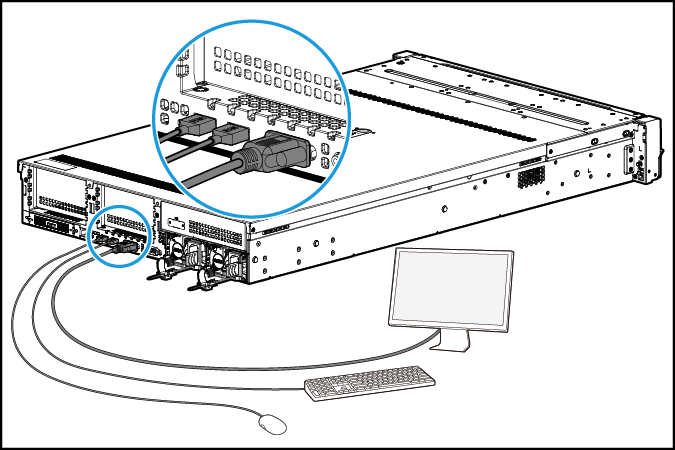
To sign in to iFIST on a server directly, you must connect a monitor, a mouse, and a keyboard to the server.
For a rack server such as an H3C UniServer R4900 G3 server:
· Connect the monitor to the server through the VGA connector.
· Connect the mouse and keyboard to the server through the USB connectors.
Figure 1 Connecting a monitor, a mouse, and a keyboard to a rack server
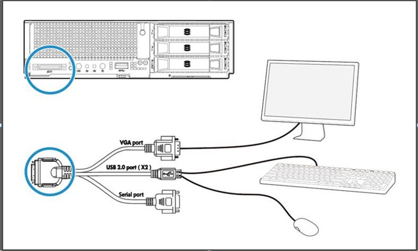
For a blade server such as an H3C UniServer B5800 G3 server, connect the monitor, mouse, and keyboard to the server through SUV connectors, as shown in Figure 2.
Figure 2 Connecting a monitor, a mouse, and a keyboard to a blade server
Prerequisites for a iFIST sign-in through the HDM remote console
Prepare the hardware environment for signing in to iFIST through HDM. For more information, see H3C Servers HDM User Guide.
Procedure
1. Launch the remote console from the HDM Web interface. For more information, see H3C Servers HDM User Guide.
Skip this step if a local direct KVM connection is used.
2. Reboot the server.
3. On the POST screen shown in Figure 3, press F10.
Figure 3 Launching iFIST from the POST screen (BIOS version 2.00.26)
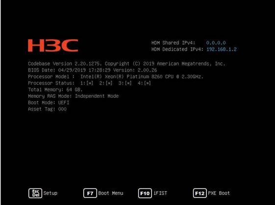
4. (Optional) If the BIOS startup page does not display the iFIST boot option, press ESC to enter the BIOS Setup. Click on the Boot options to check whether the iFIST boot option is enabled. If it is not, enable the iFIST boot option and restart the server to enter the BIOS startup screen again.
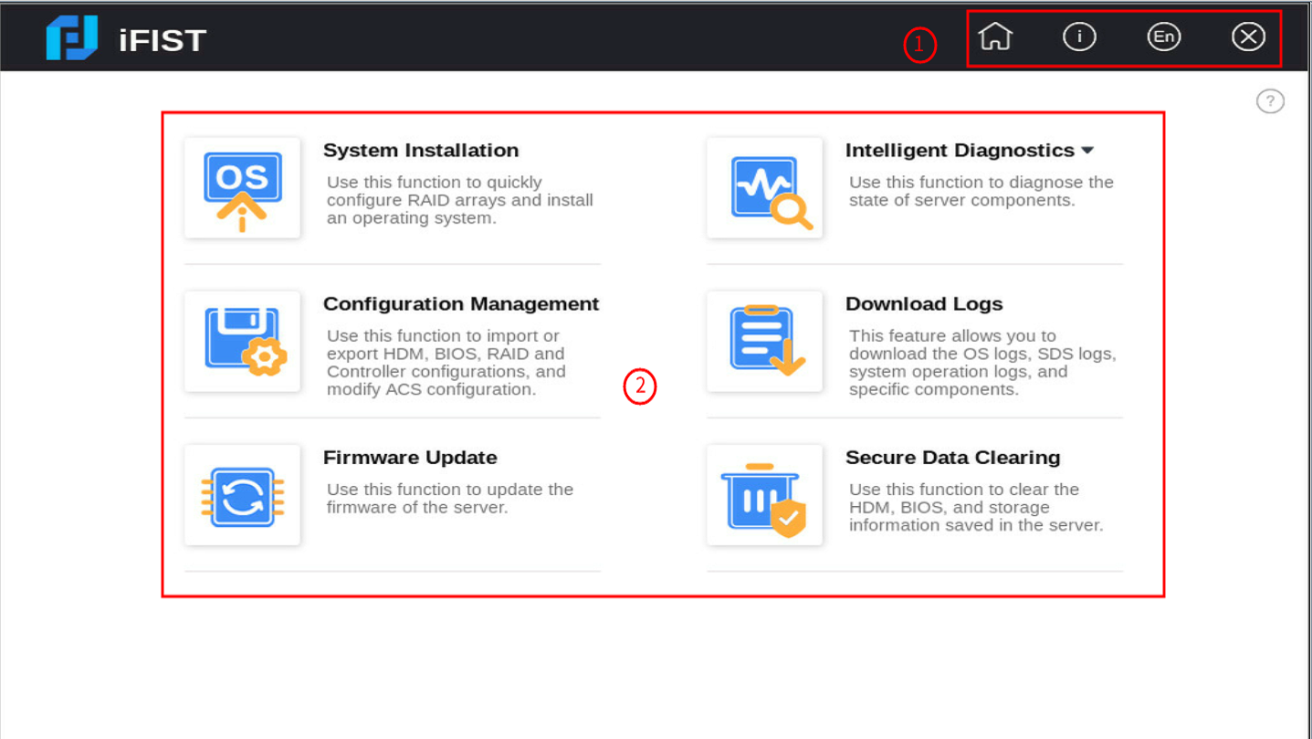
5. The Web interface of iFIST is displayed, as shown in Figure 4.
iFIST Web interface
As shown in Figure 4, the iFIST Web interface contains the following areas:
|
Area |
Description |
|
Administrative section |
Provides the following management options: · · · · |
|
Work pane |
Displays links to the functions provided by iFIST. To obtain help information when you use
iFIST, click the question mark icon |
Figure 4 iFIST Web interface
System installation
Automated OS installation
About this feature
You can install the following types of operating systems through the iFIST OS installation wizard:
· Red Hat Enterprise Linux.
· SuSE Linux Enterprise Server.
· CentOS.
· Ubuntu Server.
· VMware ESXi.
· CAS.
· Oracle Linux.
· Windows Server (except Windows Core OS).
Application scenarios
· The storage controller driver in not integrated in the OS image, resulting in hard drive recognition failures during the installation process.
· Manual intervention is required during the OS installation process.
· After the operating system is installed, you need to manually install the required drivers.
Overview
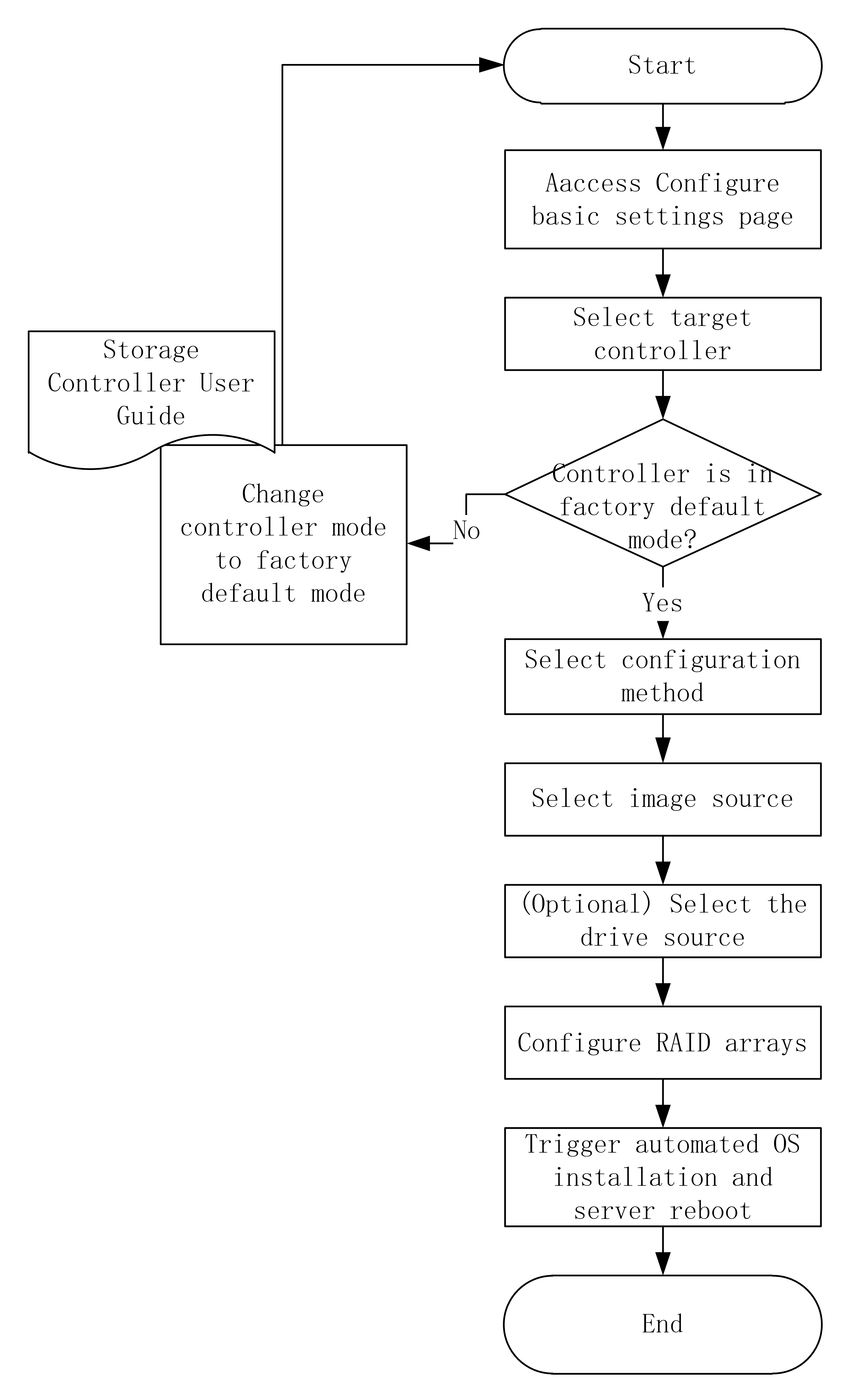
The procedure of automated OS installation is as shown in Figure 5.
Prerequisites
Before using the OS installation wizard, complete the following tasks:
· Mount the storage media that contains the OS image to the server. Supported storage media include CD (physical CD or HDM virtual media) and USB flash drive.
· If driver installation is required, mount to the server the storage media that contains a REPO image file in a format matching the ISO image format. iFIST cannot recognize compressed driver installation packages.
· If iFIST is accessed through the HDM remote console, you must mount both the OS image file and REPO image file to the HDM remote console.
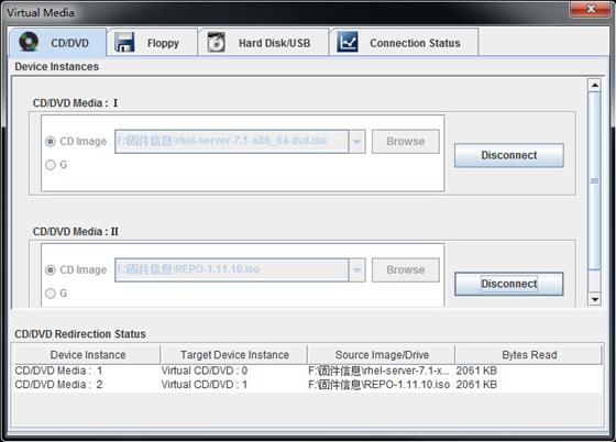
Figure 6 shows an example of mounting to the KVM remote console the OS image file and REPO image file stored on a virtual CD.
Figure 6 Mounting the OS image file and REPO image file
Restrictions and guidelines
When you use the iFIST OS installation wizard, follow these restrictions and guidelines:
· Before installing the OS, make sure the server has only one bootable image file mounted. If the server has multiple bootable image files mounted, the server might fail to locate the correct boot files and OS installation will fail.
· Do not remove the image source during OS installation. An image file can only be edited in basic settings.
· Do not intervene manually during operating system installation.
Procedure
1. On the iFIST home page, click System Installation.
The OS installation wizard displays the Configure basic settings page, as shown in Figure 7.
Figure 7 Configuring basic settings
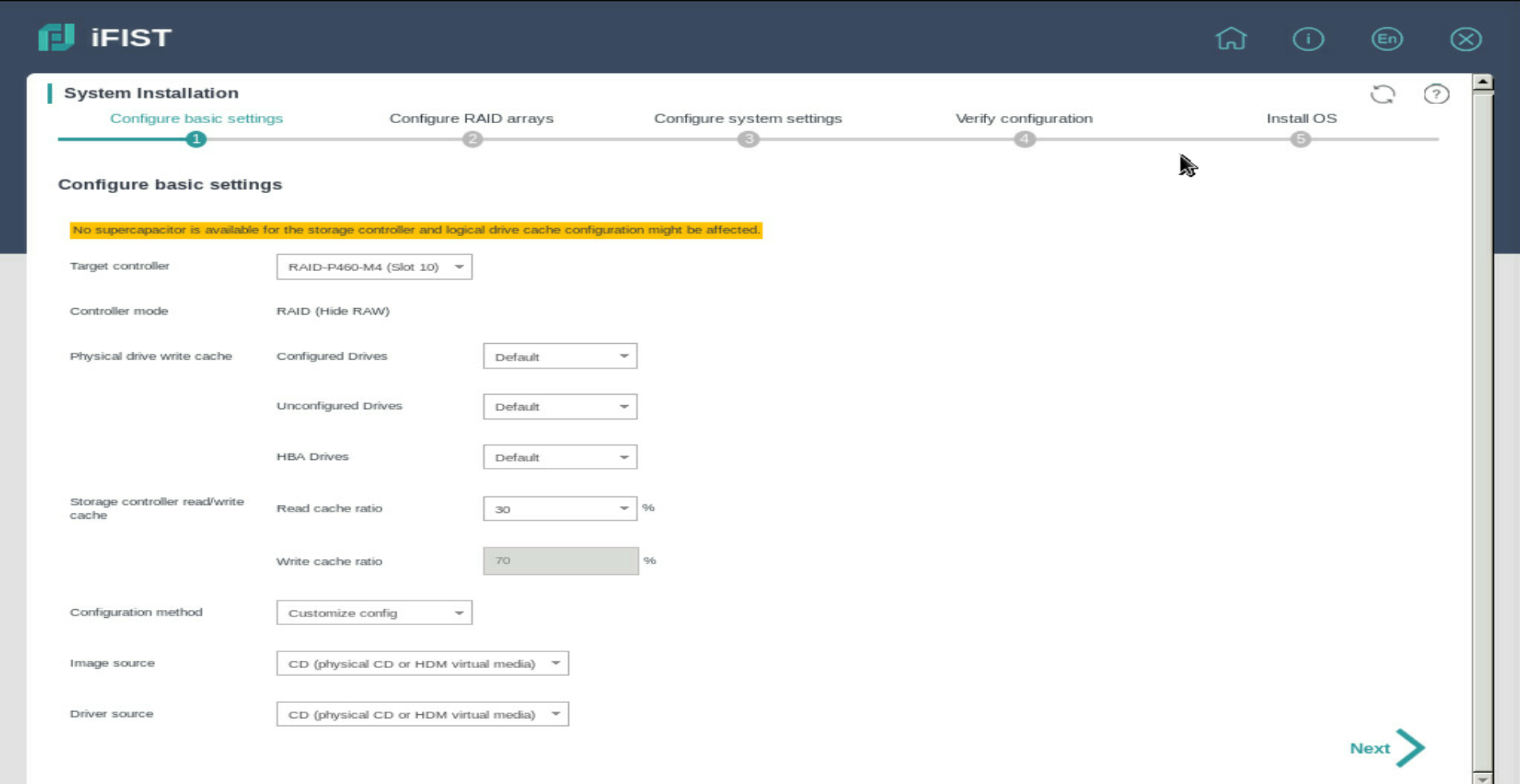
2. Select the storage controller to be configured from the Target controller list.
3. Check the Controller mode field to verify that the controller is operating in the supported mode. For information about the controller working mode, see H3C Servers iFIST Online Help. For parameter descriptions for JBOD mode of the LSI storage controller on the page, see Table 1.
|
Parameter |
Description |
|
JBOD |
JBOD—Indicates whether the Just a Bunch Of Disks (JBOD) mode is enabled or disabled. The value can be ON or OFF. l ON—The JBOD mode is enabled. The operating system can have access to a disk directly without creating a RAID volume first. l OFF—The JBOD mode is disabled. The operating system is not able to see a disk until the disk in included in a RAID volume. This parameter is not displayed if the storage controller does not support the JBOD attribute. |
4. From the Global write cache list, select a global write cache mode for the physical drives attached to the controller. Alternatively, set the write cache mode for drives in the Physical drive write cache area.
|
|
IMPORTANT: To ensure successful configuration file import into a server, make sure the following conditions are met: · For a server installed with multiple storage controllers, the number of installed storage controllers must be equal to or greater than the number of storage controllers specified in the configuration file; the type, mode, and slot specified for each storage controller in the configuration file must match the type, mode, and slot of each storage controller installed in the server. · If you fail to import the configuration file to a server installed with multiple storage controllers, you can use other methods to install OS to the storage controllers. · For each logical drive in the file, all the member physical drives must be present on the corresponding slots of the server and must meet the following requirements: If a PMC controller is used, the drives must be in Raw, Ready, or Online state. If an LSI controller is used, the drives must be in Unconfigured Good, Unconfigured Bad, or Online state. The physical drives of an HBA-LSI-9300-8i-A1-X controller must be in Ready state. The physical drives of an HBA-LSI-9311-8i-A1-X controller must be in Ready or Optimal state. · If the Import config file configuration method is used, iFIST automatically creates the logical drives by using all the available capacities of the member drives on the server. The logical drive capacity settings in the configuration file are not imported. · The file must be stored on a USB flash drive formatted with the FAT32 or NTFS file system. |
5. Select the type of media where the OS image file resides.
6. (Optional.) Select the driver source. Options are CD (physical CD or HDM virtual media) and USB flash drive.
|
|
IMPORTANT: To ensure successful configuration file import into a server, make sure the following conditions are met: · For a server installed with multiple storage controllers, the number of installed storage controllers must be equal to or greater than the number of storage controllers specified in the configuration file; the type, mode, and slot specified for each storage controller in the configuration file must match the type, mode, and slot of each storage controller installed in the server. · If you fail to import the configuration file to a server installed with multiple storage controllers, you can use other methods to install OS to the storage controllers. · For each logical drive in the file, all the member physical drives must be present on the corresponding slots of the server and must meet the following requirements: If a PMC controller is used, the drives must be in Raw, Ready, or Online state. If an LSI controller is used, the drives must be in Unconfigured Good, Unconfigured Bad, or Online state. The physical drives of an HBA-LSI-9300-8i-A1-X controller must be in Ready state. The physical drives of an HBA-LSI-9311-8i-A1-X controller must be in Ready or Optimal state. · If the Import config file configuration method is used, iFIST automatically creates the logical drives by using all the available capacities of the member drives on the server. The logical drive capacity settings in the configuration file are not imported. · The file must be stored on a USB flash drive formatted with the FAT32 or NTFS file system. |
7. Enter RAID configuration page.
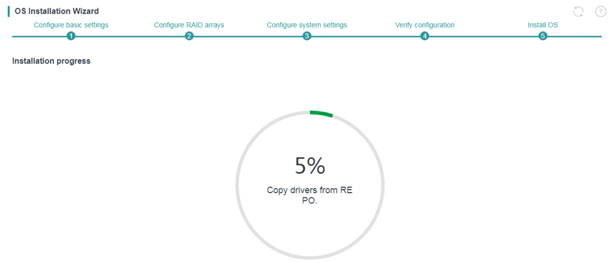
8. Install OS. The Install OS page displays the installation progress, as shown in Figure 8. The server is automatically restarted after the OS installation is complete without manual intervention.
|
|
NOTE:. · Do not remove the boot media before the OS installation is complete. · After the OS installation is complete, install the related drivers as soon as possible to ensure correct operation of the operating system. · The server might automatically restart multiple times during installation of a Windows operating system. · After an OS is installed, the first boot option changes to HDD. You can log in to HDM or enter the BIOS setup utility to modify system boot options. For more information, see H3C Servers HDM User Guide and H3C Servers User Guide. |
Configuring RAID arrays
About this feature
RAID array configuration involves RAID creation, physical drive management, and logical drive management. Server manufacturers achieve this feature by installing storage controllers on servers. The iFIST system integrates drivers for storage controllers, along with management tools and API interfaces from other manufacturers, offering a unified web interface to streamline the RAID creation process.
Application scenarios
You can rapidly create logical drives by utilizing different storage controller cards.
Overview
The procedure of RAID configuration is as shown in Figure 9.
Restrictions and guidelines
· If a PMC controller is used, the controller mode must be RAID (Hide-RAW), HBA, or Mixed.
If a RAID-P430-M1 or RAID-P430-M2 controller is used, the controller mode must be RAID (Hide-RAW) or RAID (Expose-RAW).
· If an LSI controller is used, the controller mode must be RAID.
· To install an operating system on a server in UEFI boot mode, make sure only the system drive (target logical drive) contains a UEFI partition. Operating system installation will fail if a UEFI partition exists on a non-system drive.
· The OS installation wizard does not support OS installation or RAID configuration on the onboard RAID controller.
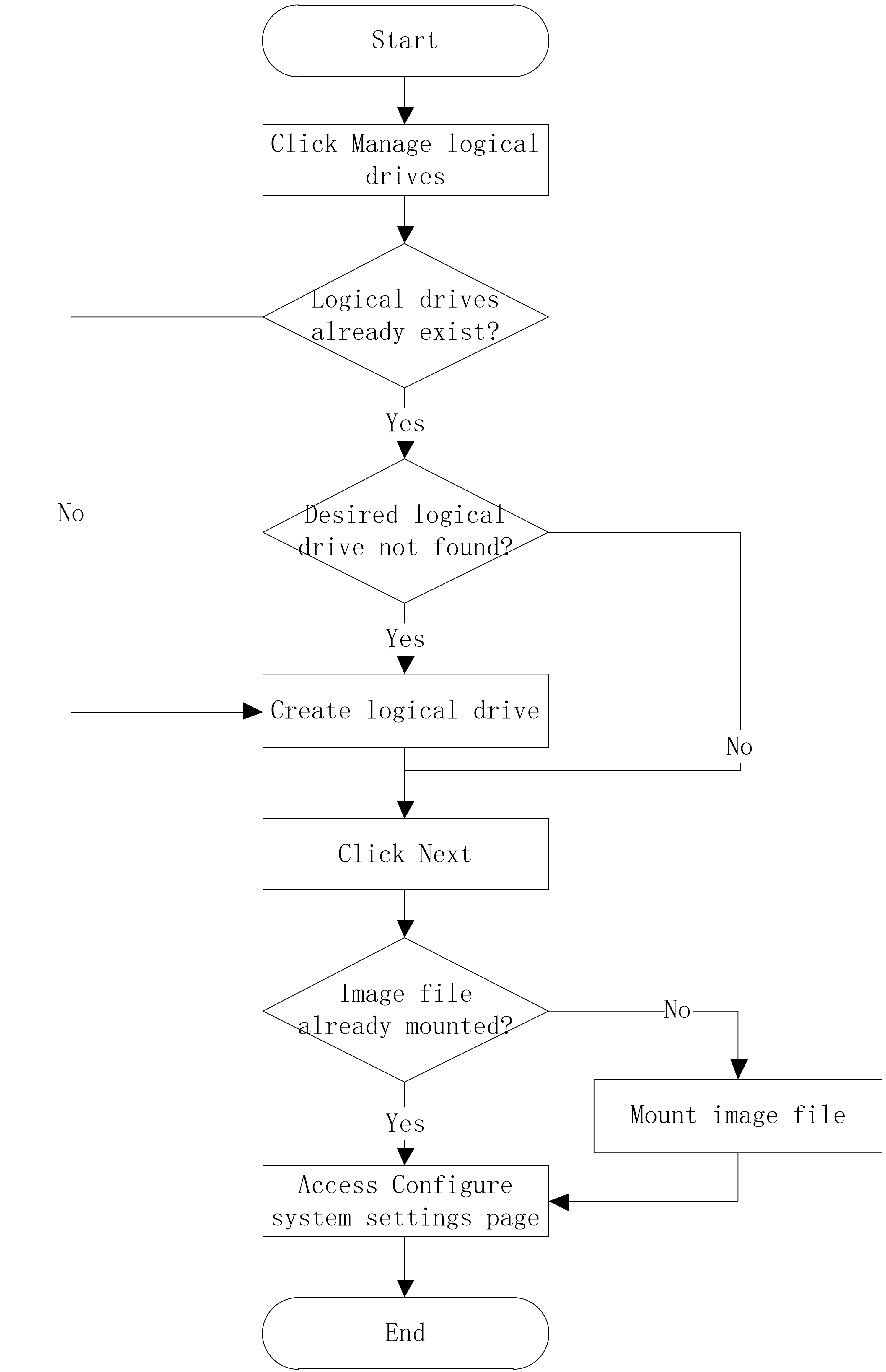
Procedure
|
|
IMPORTANT: · To install an operating system on a physical drive, directly click Next on the Create RAID array tab to skip the RAID configuration procedure and go to the system settings step. · Hot spare management is available only for the P460 and H460 storage controllers on rack servers. If an error occurs on hot spare management for such a storage controller, update the firmware version of the storage controller first. |
1. On the Manage logical drives tab, on the logical drive management page, you can view the information of configured logical drives..
Figure 10 Manage logical drives
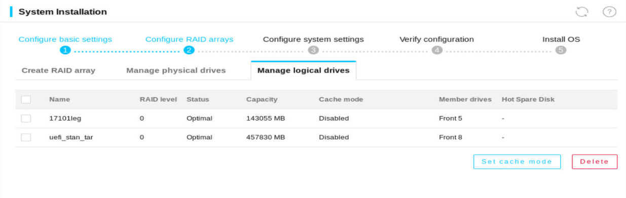
2. Identify whether the logical drive on which you want to install the operating system already exists.
a. If the logical drive already exists, click Next to go to the next step directly.
b. If the logical drive list does not contain such a logical drive, click the Create RAID array tab.
3. On the Configure RAID arrays page, it displays physical drives available for RAID configuration.
Figure 11 Create RAID array tab
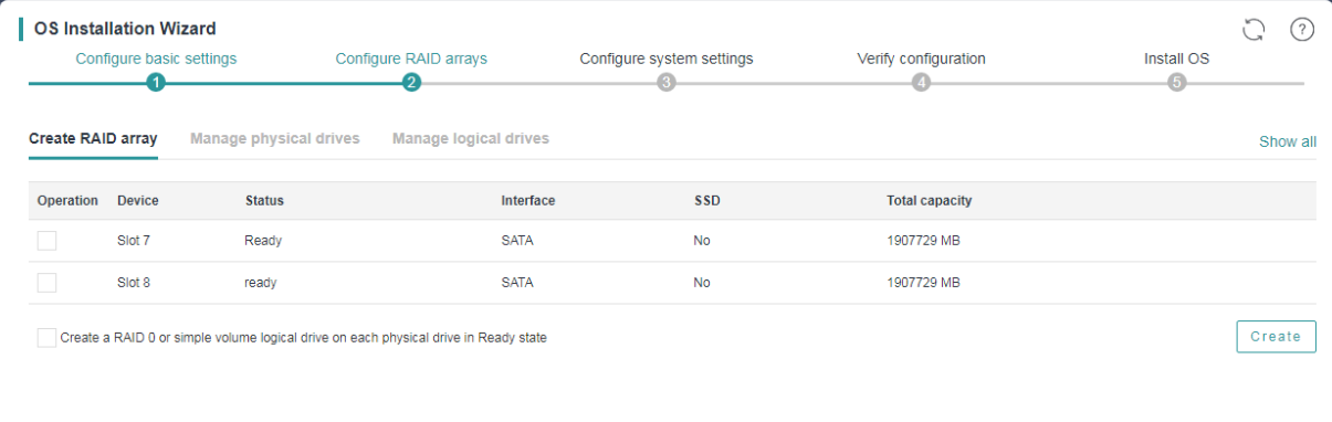
4. To create a RAID 0 or simple volume logical drive on each physical drive in Ready or Unconfigured Good state:
a. Select the Create a RAID 0 or simple volume logical drive on each physical drive in Ready state option.
b. Click Create.
c. In the confirmation dialog box that opens, click OK.
This feature is not available if an HBA-LSI-9311-8i-A1-X controller is used.
5. Select the physical drives for RAID configuration and click the Create.
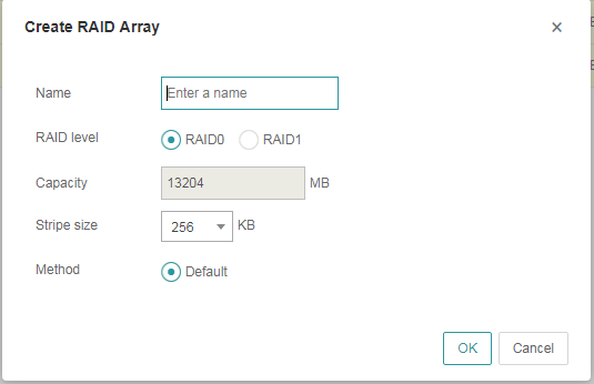
6. Set the name, RAID level, stripe size, and initialization method for the RAID array, then Click OK.
Figure 12 Create RAID Array window (HBA controller)
7. Click Manage physical drives tab to view all status of physical drives. For more information about parameters of physical drive see H3C Servers iFIST User Guide.
Figure 13 Manage physical drives tab
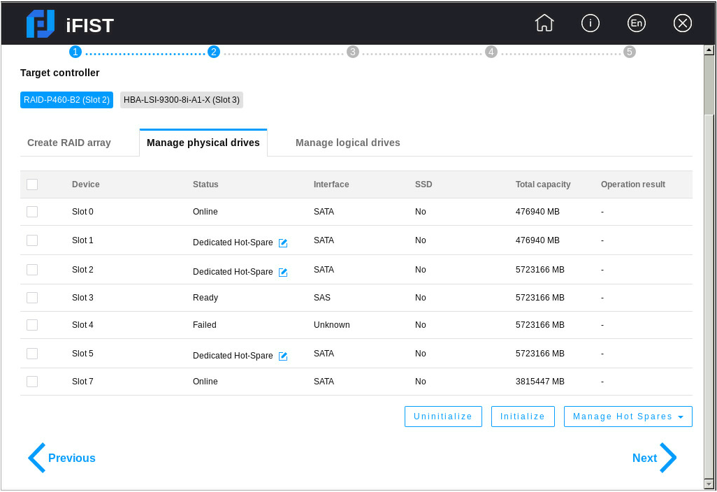
8. Check if the state of physical drives is available for RAID configuration.
· If a PMC controller is used, you can click Unintialize or Initialize to uninitialize or initialize the drives.
· If an LSI controller is used, you can click Set JBOD State to set the state of the selected drives to JBOD. You can also click Set state to set the state of the physical drives to Unconfigured Good.
9. (Optional) Select physical drive, click Set cache mode to set the cache mode for the drives as shown in Figure 14.
Figure 14 Set Cache Mode window
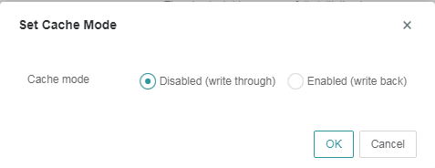
Table 2 Descritions of physical drive cache parameter
|
Parameter |
Description |
|
Cache mode (Optional) |
The cache mode option is available for a PMC controller (except a PMC HBA or UN-RAID-P460-M4 RAID controller). This parameter is displayed when the global write cache mode is Drive Specific. Cache mode—Select a cache mode. Options are: l Disabled (write through)—New data is written to the cache and the physical drive at the same time. Writing data will experience latency as the data need to be written to two places. l Enabled (write back)—New data is written only to the cache. The data is written to the physical drive only when it needs to be replaced and removed from the cache. This mode boasts low latency but entails data loss risks because a power failure might prevent the data from being written to the physical drive. |
10. Click the Manage logical drives tab to check configured logical drives.
11. (Optional) To set the cache mode for a logical drive:
a. Select the logical drive.
b. Click Set cache mode.
c. In the Set Cache Mode window that opens, select a cache mode and click OK.
Figure 15 Set Cache Mode window for an LSI RAID controller
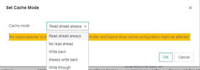
Figure 16 Set Cache Mode window for a PMC RAID controller
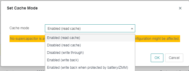
Table 3 Descritions of cache parameter
|
Parameter |
Description |
|
Cache mode (Optional) |
Allows you to set the read and write policies for the selected logical drives. A supercapacitor must be available to power the cache module in case of power failures to ensure data integrity. This option is available only when the RAID controller supports power fail safeguard. Supported read and write policies are: l Read ahead always/Enabled (read cache)—Always use the read-ahead policy. When retrieving data from the logical drive, the system also retrieves subsequent data and saves the subsequent data to the cache. Then, the subsequent data can be retrieved from the cache directly when requested. The read-ahead policy reduces the hard drive seek time and improves data retrieval efficiency. To use this policy, make sure the RAID controller supports power fail safeguard. This policy entails data security risks because data loss might occur in case of supercapacitor exceptions. l No read ahead/Disabled (read cache)—Use the no-read-ahead policy. The system starts to retrieve data from the logical drive only when the data read request is received by the RAID controller. l Write back/Enabled (write back when protected by battery/ZMM)—Use the write-back policy. If the RAID controller has a functional BBU present, data is written first to the controller cache before being written to the drive. If the RAID controller does not have a functional BBU present, write-through is resumed and data is written directly to the drive. l Always write back/Enabled (write back)—Use the always-write-back policy. The controller sends a write-request completion signal as soon as the data is in the controller cache but has not yet been written to the drive. This policy improves write efficiency but requires that the RAID controller support power fail safeguard. This policy entails data security risks because data loss might occur in cases of supercapacitor exceptions. l Write through/Disabled (write through)—Use the write-through policy. The controller writes data to the drive directly without first writing the data to the cache. It sends a write-request completion signal only after the data is written to the drive. This policy does not require that the RAID controller support power fail safeguard and does not entail data loss risks in the event of supercapacitor exceptions. However, the write efficiency is relatively low. |
12. Click Next to enter Configure system settings page.
Configuring system settings
About this feature
You can select the driver to install and configure the relevant parameters for the operating system.
Application scenarios
After you mount the image file, you need to configure parameters for different drivers.
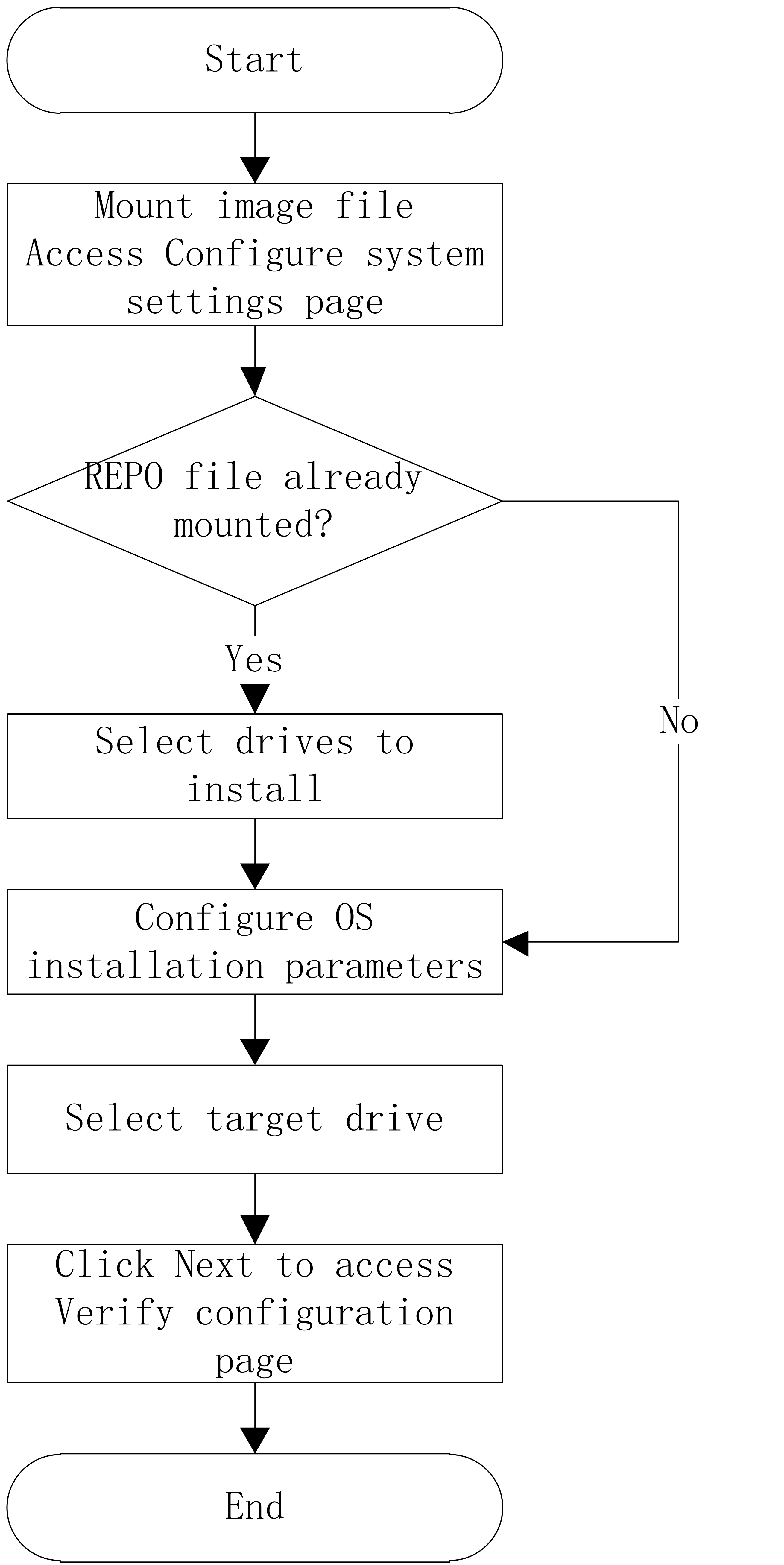
Overview
The procedure of configuring system settings is as shown in Figure 17.
Restrictions and guidelines
· The configuration parameters in this task vary by the image to be installed.
· If the REPO image is mounted when you install a VMware ESXi operating system, iFIST does not support selecting or automatically installing drivers from the REPO image.
Procedure
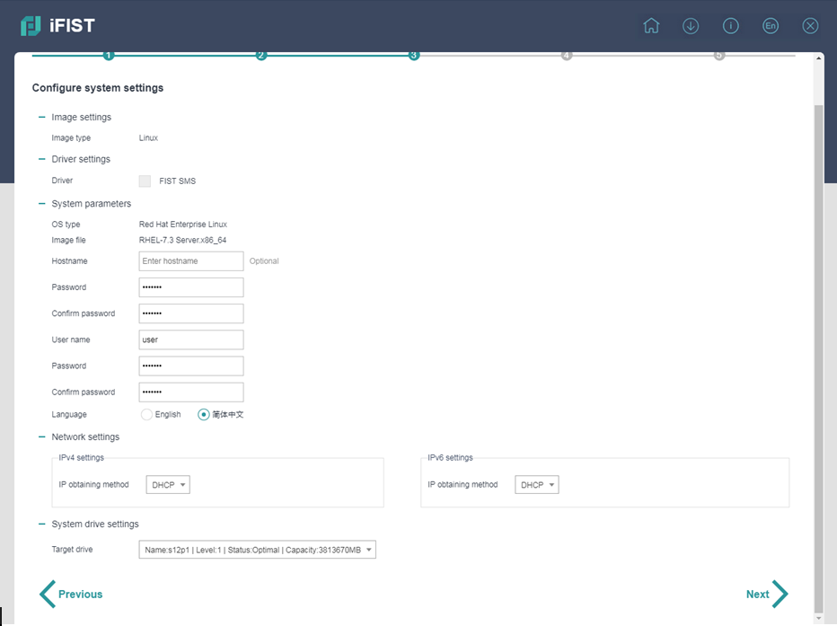
1. On the Configure system settings page, configure the operating system-specific parameters as follows:
¡ For a Linux operating system, specify the hostname (optional), root password, username, user password, language, and network settings, as shown in Figure 18.
Figure 18 Setting the parameters for installing a Linux operating system
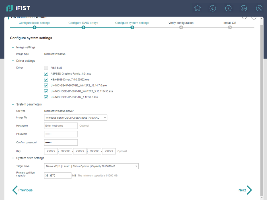
¡ For a Microsoft Windows operating system, select the drivers to install, set the image file, hostname (optional), password (optional), key (optional), and primary partition capacity, as shown in Figure 19. The available drivers include all iFIST built-in drivers listed in H3C Servers iFIST User Guide.
Figure 19 Setting the parameters for installing a Windows operating system
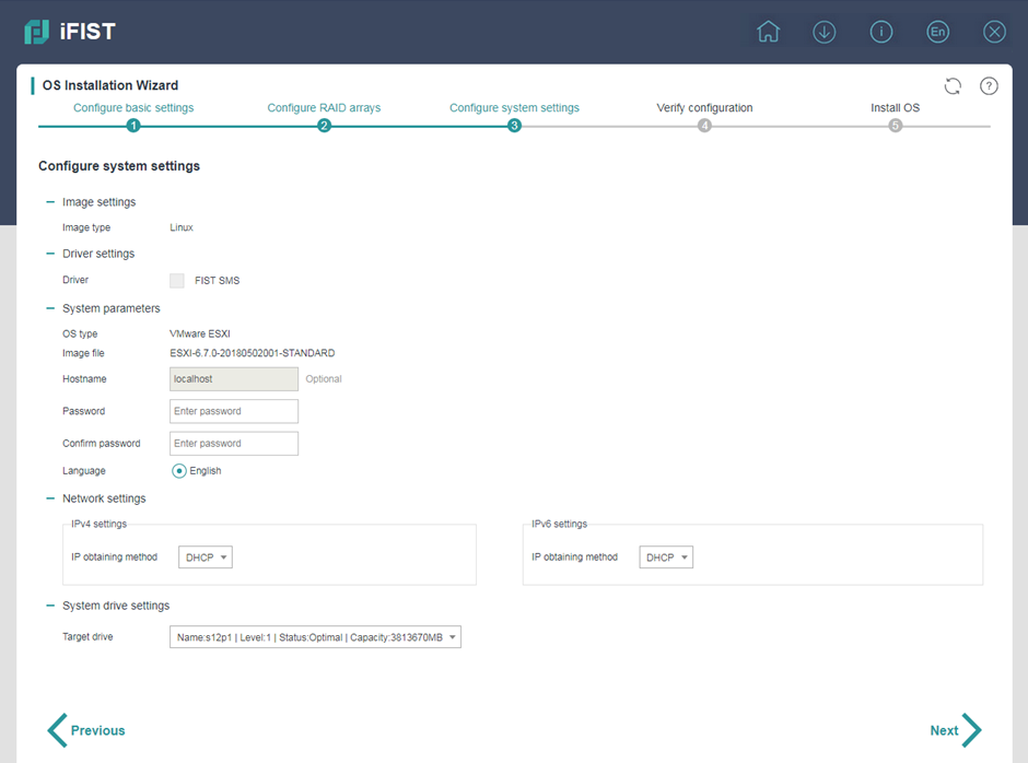
¡ For a VMware ESXi operating system, set the hostname (optional), root password, and network settings, as shown in Figure 20.
Figure 20 Setting the parameters for installing a VMware ESXi operating system
2. In the Target drive field, enter the primary partition capacity (If a Linux operating system is to be installed, the maximum capacity of the target drive is used as the primary partition capacity by default and cannot be changed.).
3. Click Next.
Verifying the configuration
About this feature
(Optional) You can review the configuration to confirm if the information is correct, and export the operating system and RAID configuration parameters.
Application scenarios
It is necessary to verify the image configuration, driver configuration, parameter configuration, and system settings information, and present the configuration information in the form of a file.
Overview
The procedure of verifying the configuration is as shown in Figure 21.
Restrictions and guidelines
In iFIST-1.35 or earlier, the configuration file is exported to the root directory of the USB flash drive. In iFIST-1.36 or later, the configuration file is exported to the /iFIST/OsInstall directory of the USB flash drive.
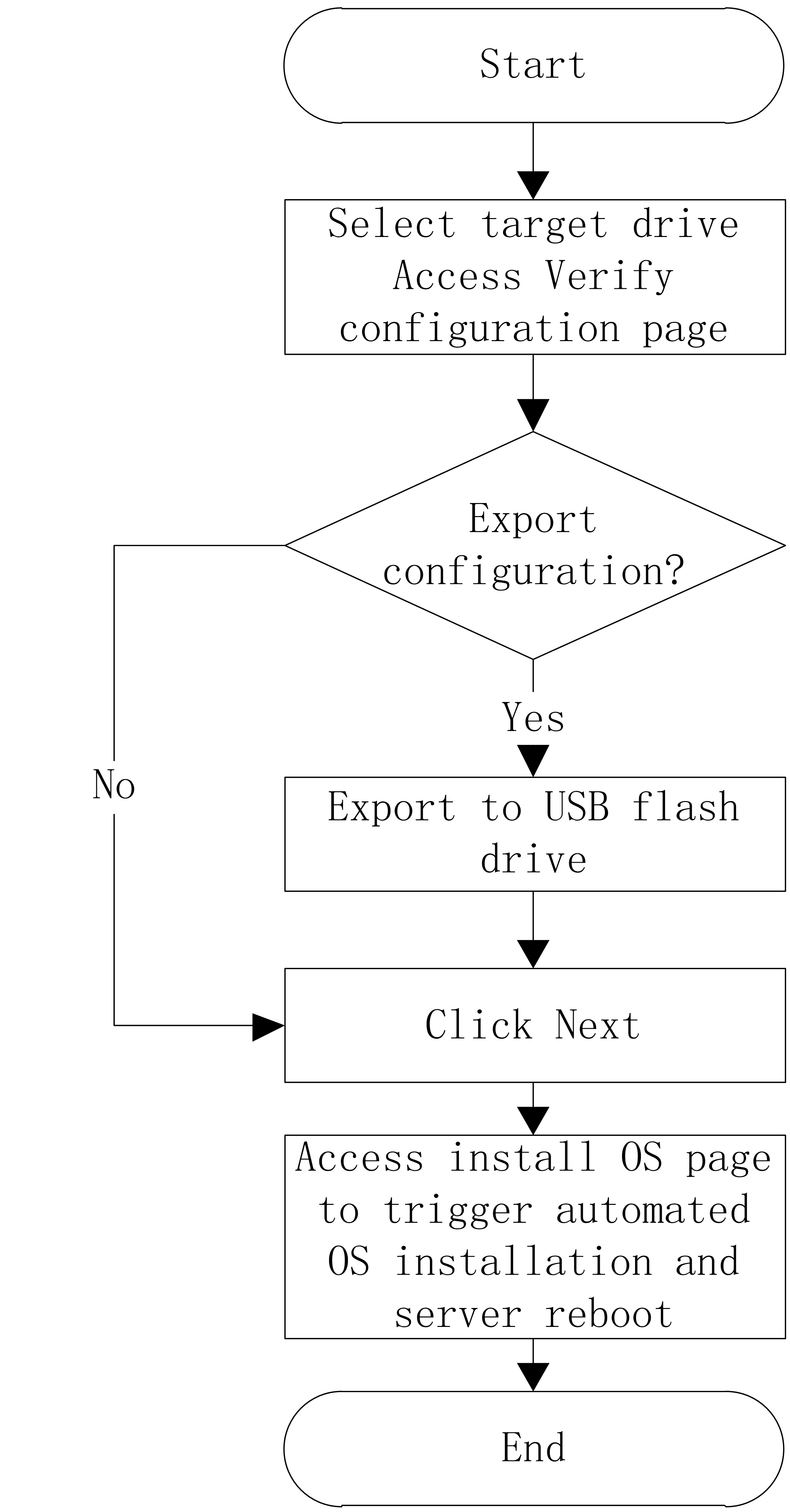
Procedure
1. On the Verify configuration page, verify that the operating system installation settings are correct.
a. If no revision is required, click Next.
b. If revision is required, click Previous, return to the Configure system settings page to revise.
Figure 22 Verifying and exporting the configuration
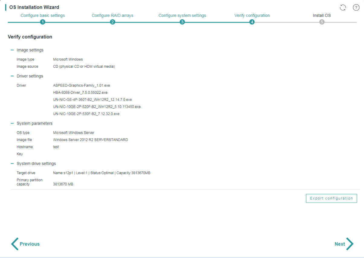
2. (Optional) To export the RAID and operating system installation settings to a file:
a. Click Export configuration.
b. Select the storage device where you want to store the exported file and set the exported file format (xml or img).
The exported file is MD5-encrypted to prevent file tampering.
c. Click OK.
You can import the configuration file into another server on the Configure basic settings page by selecting USB flash drive or floppy drive.
Supported lists
Supported operating systems
You can install the following types of operating systems through the iFIST OS installation wizard:
· Red Hat Enterprise Linux.
· SuSE Linux Enterprise Server.
· CentOS.
· Ubuntu Server.
· VMware ESXi.
· CAS.
· Oracle Linux.
· Windows Server.
Table 4 lists the operating systems and their versions that can be installed through the iFIST OS installation wizard.
Table 4 Supported operating systems
|
OS type |
Version |
|
Red Hat Enterprise Linux |
Red Hat Enterprise Linux 6.7 (64 bit) (includes KVM) |
|
Red Hat Enterprise Linux 6.8 (64 bit) (includes KVM) |
|
|
Red Hat Enterprise Linux 6.9 (64 bit) (includes KVM) |
|
|
Red Hat Enterprise Linux 6.10 (64 bit) (includes KVM) |
|
|
Red Hat Enterprise Linux 7.2 (64 bit) (includes KVM) |
|
|
Red Hat Enterprise Linux 7.3 (64 bit) (includes KVM) |
|
|
Red Hat Enterprise Linux 7.4 (64 bit) (includes KVM) |
|
|
Red Hat Enterprise Linux 7.5 (64 bit) (includes KVM) |
|
|
Red Hat Enterprise Linux 7.6 (64 bit) (includes KVM) |
|
|
Red Hat Enterprise Linux 7.7 (64 bit) (includes KVM) |
|
|
Red Hat Enterprise Linux 7.8 (64 bit) (includes KVM) |
|
|
Red Hat Enterprise Linux 7.9 (64 bit) (includes KVM) |
|
|
Red Hat Enterprise Linux 8.0 (64 bit) (includes KVM) |
|
|
Red Hat Enterprise Linux 8.1 (64 bit) (includes KVM) |
|
|
Red Hat Enterprise Linux 8.2 (64 bit) (includes KVM) |
|
|
Red Hat Enterprise Linux 8.3 (64 bit) (includes KVM) |
|
|
Red Hat Enterprise Linux 8.4 (64 bit) (includes KVM) |
|
|
Red Hat Enterprise Linux 8.5 (64 bit) (includes KVM) |
|
|
Red Hat Enterprise Linux 8.6 (64 bit) (includes KVM) |
|
|
Red Hat Enterprise Linux 8.7 (64 bit) (includes KVM) |
|
|
Red Hat Enterprise Linux 8.8 (64 bit) (includes KVM) |
|
|
Red Hat Enterprise Linux 8.9 (64 bit) (includes KVM) |
|
|
Red Hat Enterprise Linux 8.10 (64 bit) (includes KVM) |
|
|
Red Hat Enterprise Linux 9.0 (64 bit) (includes KVM) |
|
|
Red Hat Enterprise Linux 9.1 (64 bit) (includes KVM) |
|
|
Red Hat Enterprise Linux 9.2 (64 bit) (includes KVM) |
|
|
Red Hat Enterprise Linux 9.3 (64 bit) (includes KVM) |
|
|
Red Hat Enterprise Linux 9.4 (64 bit) (includes KVM) |
|
|
Red Hat Enterprise Linux 9.5 (64 bit) (includes KVM) |
|
|
SuSE Linux Enterprise Server |
SLES 11 SP4 (64 bit) (includes XEN & KVM) |
|
SLES 12 (64 bit) SP1 (includes XEN & KVM) |
|
|
SLES 12 (64 bit) SP2 (includes XEN & KVM) |
|
|
SLES 12 (64 bit) SP3 (includes XEN & KVM) |
|
|
SLES 12 (64 bit) SP4 (includes XEN & KVM) |
|
|
SLES 12 (64 bit) SP5 (includes XEN & KVM) |
|
|
SLES 15 (64 bit) (includes XEN & KVM) |
|
|
SLES 15 (64 bit) SP1 (includes XEN & KVM) |
|
|
SLES 15 (64 bit) SP2 (includes XEN & KVM) |
|
|
SLES 15 (64 bit) SP3 (includes XEN & KVM) |
|
|
SLES 15 (64 bit) SP4 (includes XEN & KVM) |
|
|
SLES 15 (64 bit) SP5 (includes XEN & KVM) |
|
|
SLES 15 (64 bit) SP6 (includes XEN & KVM) |
|
|
CentOS |
CentOS 6.10 (64 bit) |
|
CentOS 7.3 (64 bit) |
|
|
CentOS 7.4 (64 bit) |
|
|
CentOS 7.5 (64 bit) |
|
|
CentOS 7.6 (64 bit) |
|
|
CentOS 7.7 (64 bit) |
|
|
CentOS 7.8 (64 bit) |
|
|
CentOS 7.9 (64 bit) |
|
|
CentOS 8.0 (64 bit) |
|
|
CentOS 8.1 (64 bit) |
|
|
CentOS 8.2 (64 bit) |
|
|
CentOS 8.3 (64 bit) |
|
|
CentOS 8.4 (64 bit) |
|
|
VMware ESXi |
VMware ESXi 6.5 U1 (64 bit) |
|
VMware ESXi 6.5 U2 (64 bit) |
|
|
VMware ESXi 6.5 U3 (64 bit) |
|
|
VMware ESXi 6.7 (64 bit) |
|
|
VMware ESXi 6.7 U3 (64 bit) |
|
|
VMware ESXi 7.0 (64 bit) |
|
|
VMware ESXi 7.0 U2 (64 bit) |
|
|
VMware ESXi 7.0 U3 (64 bit) |
|
|
VMware ESXi 8.0 (64 bit) |
|
|
Ubuntu Server |
Ubuntu Server 17.10 (64 bit) – LTS |
|
Ubuntu Server 17.10.1 (64 bit) – LTS |
|
|
Ubuntu Server 18.04 (64 bit) – LTS |
|
|
Ubuntu Server 18.04.1 (64 bit) – LTS |
|
|
Ubuntu Server 18.04.2 (64 bit) – LTS |
|
|
Ubuntu Server 18.04.3 (64 bit) – LTS |
|
|
Ubuntu Server 18.04.4 (64 bit) - LTS |
|
|
Ubuntu Server 18.04.5 (64 bit) - LTS |
|
|
Ubuntu Server 20.04 (64 bit) - LTS |
|
|
Ubuntu Server 20.04.1 (64 bit) - LTS |
|
|
Ubuntu Server 20.04.2 (64 bit) - LTS |
|
|
Ubuntu Server 20.04.4 (64 bit) - LTS |
|
|
Ubuntu Server 20.04.5 (64 bit) - LTS |
|
|
Ubuntu Server 20.04.6 (64 bit) - LTS |
|
|
Ubuntu Server 22.04 (64 bit) - LTS |
|
|
Ubuntu Server 22.04.1 (64 bit) - LTS |
|
|
Ubuntu Server 22.04.2 (64 bit) - LTS |
|
|
Ubuntu Server 22.04.3 (64 bit) - LTS |
|
|
Ubuntu Server 22.04.4 (64 bit) - LTS |
|
|
Ubuntu Server 22.04.5 (64 bit) - LTS |
|
|
Ubuntu Server 22.04.1 (64 bit) - LTS |
|
|
CAS |
CAS-E0513 |
|
CAS-E0526 |
|
|
CAS-E0782 |
|
|
Oracle Linux |
Oracle Linux 8.0 |
|
Oracle Linux 8.1 |
|
|
Oracle Linux 8.2 |
|
|
Oracle Linux 8.3 |
|
|
Oracle Linux 8.4 |
|
|
Oracle Linux 8.6 |
|
|
Oracle Linux 8.7 |
|
|
Oracle Linux 8.8 |
|
|
Oracle Linux 8.9 |
|
|
Oracle Linux 8.10 |
|
|
Oracle Linux 9.0 |
|
|
Oracle Linux 9.1 |
|
|
Oracle Linux 9.2 |
|
|
Oracle Linux 9.3 |
|
|
Oracle Linux 9.4 |
|
|
Oracle Linux 9.5 |
|
|
openEuler |
openEuler-20.03-LTS-x86_64-dvd.iso |
|
openEuler-20.03-LTS-SP1-x86_64-dvd |
|
|
openEuler-20.03-LTS-SP2-x86_64-dvd |
|
|
openEuler-20.03-LTS-SP3-x86_64-dvd |
|
|
openEuler-20.03-LTS-SP4-x86_64-dvd |
|
|
openEuler-22.03-LTS-SP1-x86_64-dvd |
|
|
openEuler-22.03-LTS-SP2-x86_64-dvd |
|
|
openEuler-22.03-LTS-SP4-x86_64-dvd |
|
|
openEuler-22.03-LTS-x86_64-dvd |
|
|
openEuler-22.03-LTS-SP3-aarch64-dvd |
|
|
openEuler-22.03-LTS-SP3-dvd |
|
|
Kylin |
Kylin-Server-V10-SP1-x86_64 |
|
Kylin-Server-V10-SP2-x86_64 |
|
|
Kylin-Server-V10-SP3-x86_64 |
|
|
Rocky Linux |
Rocky Linux 8.4 x86_64 dvd |
|
Rocky Linux 8.5 x86_64 dvd |
|
|
Rocky Linux 8.6 x86_64 dvd |
|
|
Rocky Linux 8.7 x86_64 dvd |
|
|
Rocky Linux 8.8 x86_64 dvd |
|
|
Rocky Linux 8.9 x86_64 dvd |
|
|
Rocky Linux 8.10 x86_64 dvd |
|
|
Rocky Linux 9.0 x86_64 dvd |
|
|
Rocky Linux 9.1 x86_64 dvd |
|
|
Rocky Linux 9.2 x86_64 dvd |
|
|
Rocky Linux 9.3 x86_64 dvd |
|
|
Rocky Linux 9.4 x86_64 dvd |
|
|
Rocky Linux 9.5 x86_64 dvd |
|
|
CTyunOS |
CTyunOS 2.0.1 x86_64 |
|
H3Linux |
H3Linux 2.0.2-SP01 |
|
Windows Server |
Microsoft Windows Server 2012 R2 Datacenter |
|
Microsoft Windows Server 2012 R2 Essentials |
|
|
Microsoft Windows Server 2012 R2 Standard |
|
|
Microsoft Hyper-V Server 2012 R2 |
|
|
Microsoft Windows Server 2016 Essential |
|
|
Microsoft Windows Server 2016 Standard |
|
|
Microsoft Windows Server 2016 Datacenter |
|
|
Microsoft Hyper-V Server 2016 |
|
|
Microsoft Hyper-V Server 2019 |
|
|
Microsoft Windows Server 2019 Standard |
|
|
Microsoft Windows Server 2019 Datacenter |
|
|
Microsoft Windows Server 2022 Standard |
|
|
Microsoft Windows Server 2022 Datacenter |
Supported storage controllers
The iFIST system installation supports the following types of storage controllers:
· HBA-1000-M2-1
· RAID-P430-M1
· RAID-P430-M2
· HBA-H460-M1
· RAID-P460-M4
· HBA-H460-B1
· RAID-P460-B4
· HBA-LSI-9311-8i-A1-X
· RAID-LSI-9361-8i(1G)-A1-X
· RAID-LSI-9361-8i(2G)-1-X
· RAID-LSI-9460-8i(2G)
· RAID-LSI-9460-8i(4G)
· RAID-LSI-9460-16i(4G)
· RAID-L460-M4
· RAID-P5408-Mf-8i-4GB
· HBA-H5408-Mf-8i
· HBA-LSI-9440-8i
· HBA-LSI-9300-8i-A1-X
· RAID-P4408-Mf-8i-2GB
· RAID-P2404-Mf-4i-2GB
· RAID-P5408-Ma-8i-4GB
· RAID-P4408-Ma-8i-2GB
· RAID-P460-B2
· RAID-P460-M2
· RAID-LSI-9560-LP-8i-4GB
· HBA-LSI-9400-8i
· HBA-LSI-9400-16i
· HBA-LSI-9500-LP-8i
· HBA-LSI-9500-LP-16i
· HBA-LSI-9540-LP-8i
· RAID-MARVELL-SANTACRUZ-LP-2i
iFIST built-in drivers
When you install an operating system on a server through iFIST, the available built-in drivers of iFIST vary by operating system, as shown in Table 5 and Table 6.
Table 5 iFIST built-in drivers for Windows
|
Driver name |
Driver version |
Supported OSs |
|
FC-HBA-LPe |
12.8.334.6 |
· Microsoft Windows Server 2012 R2 · Microsoft Windows Server 2016 · Microsoft Windows Server 2019 |
|
RAID-9361-8i |
6.714.18.00 |
· Microsoft Windows Server 2012 R2 · Microsoft Windows Server 2016 · Microsoft Windows Server 2019 |
|
LSI-9300-9311 |
2.51.26.00 |
· Microsoft Windows Server 2012 R2 · Microsoft Windows Server 2016 · Microsoft Windows Server 2019 |
|
LSI-MR-IMR |
7.708.18.0 |
Microsoft Windows Server 2012 R2 |
|
7.715.4.0 |
· Microsoft Windows Server 2016 · Microsoft Windows Server 2019 |
|
|
NIC-360T |
12.14.7.0 |
Microsoft Windows Server 2012 R2 |
|
12.15.184.13 |
Microsoft Windows Server 2016 |
|
|
12.18.9.6 |
Microsoft Windows Server 2019 |
|
|
NIC-530F |
7.13.161.0 |
Microsoft Windows Server 2012 R2 |
|
7.13.171.0 |
· Microsoft Windows Server 2016 · Microsoft Windows Server 2019 |
|
|
NIC-Intel500 |
3.14.214.0 |
Microsoft Windows Server 2012 R2 |
|
4.1.196.0 |
· Microsoft Windows Server 2016 · Microsoft Windows Server 2019 |
|
|
NIC-Intel700 |
1.11.101.0 |
· Microsoft Windows Server 2012 R2 · Microsoft Windows Server 2016 · Microsoft Windows Server 2019 |
|
PMC-ARC-THOR |
7.5.0.57011 |
Microsoft Windows Server 2012 R2 |
|
7.5.0.59002 |
· Microsoft Windows Server 2016 · Microsoft Windows Server 2019 |
|
|
PMC-LUXOR |
106.278.0.1043 |
· Microsoft Windows Server 2012 R2 · Microsoft Windows Server 2016 · Microsoft Windows Server 2019 |
|
ASPEED-Graphics-Family (Available only for R2700 G3, R2900 G3, R4700 G3, and R4900 G3) |
1.01 |
Microsoft Windows Server 2012 R2 |
Table 6 iFIST built-in drivers for Redhat/CentOS
|
Driver name |
Driver version |
Supported OSs |
|
FC-HBA-LPe |
12.6.240.27 |
· Red Hat Enterprise Linux 7.6 (64 bit) (includes KVM) · CentOS 7.6 (64 bit) |
|
12.8.340.9 |
· Red Hat Enterprise Linux 7.8 (64 bit) (includes KVM) · Red Hat Enterprise Linux 7.9 (64 bit) (includes KVM) · Red Hat Enterprise Linux 8.1 (64 bit) (includes KVM) · CentOS 7.8 (64 bit) · CentOS 7.9 (64 bit) · CentOS 8.1 (64 bit) |
|
|
12.8.351.46 |
· Red Hat Enterprise Linux 8.2 (64 bit) (includes KVM) · CentOS 8.2 (64 bit) |
|
|
12.6.240.53 |
· Red Hat Enterprise Linux 8.3 (64 bit) (includes KVM) · CentOS 8.3 (64 bit) |
|
|
RAID-9361-8i |
07.715.02.00 |
· Red Hat Enterprise Linux 7.6 (64 bit) (includes KVM) · Red Hat Enterprise Linux 7.8 (64 bit) (includes KVM) · Red Hat Enterprise Linux 8.1 (64 bit) (includes KVM) · Red Hat Enterprise Linux 8.2 (64 bit) (includes KVM) · CentOS 7.6 (64 bit) · CentOS 7.8 (64 bit) · CentOS 8.1 (64 bit) · CentOS 8.2 (64 bit) |
|
07.716.01.00 |
· Red Hat Enterprise Linux 7.9 (64 bit) (includes KVM) · CentOS 7.9 (64 bit) |
|
|
LSI-9300-9311 |
33.00.00.00 |
· Red Hat Enterprise Linux 7.6 (64 bit) (includes KVM) · Red Hat Enterprise Linux 8.1 (64 bit) (includes KVM) · CentOS 7.6 (64 bit) · CentOS 8.1 (64 bit) |
|
36.00.00.00 |
· Red Hat Enterprise Linux 8.2 (64 bit) (includes KVM) · CentOS 8.2 (64 bit) |
|
|
LSI-MR-IMR |
07.717.02.00 |
· Red Hat Enterprise Linux 7.6 (64 bit) (includes KVM) · Red Hat Enterprise Linux 7.8 (64 bit) (includes KVM) · Red Hat Enterprise Linux 7.9 (64 bit) · Red Hat Enterprise Linux 8.1 (64 bit) (includes KVM) · Red Hat Enterprise Linux 8.2 (64 bit) (includes KVM) · Red Hat Enterprise Linux 8.3 (64 bit) (includes KVM) · CentOS 7.6 (64 bit) · CentOS 7.8 (64 bit) · CentOS 7.9 (64 bit) · CentOS 8.1 (64 bit) · CentOS 8.2 (64 bit) · CentOS 8.3 (64 bit) |
|
NIC-360T |
5.3.5.39 |
· Red Hat Enterprise Linux 7.6 (64 bit) (includes KVM) · Red Hat Enterprise Linux 7.8 (64 bit) (includes KVM) · Red Hat Enterprise Linux 8.1 (64 bit) (includes KVM) · CentOS 7.6 (64 bit) · CentOS 7.8 (64 bit) · CentOS 8.1 (64 bit) |
|
5.3.5.61 |
· Red Hat Enterprise Linux 8.2 (64 bit) (includes KVM) · CentOS 8.2 (64 bit) |
|
|
NIC-530F |
1.714.25.1 |
· Red Hat Enterprise Linux 7.6 (64 bit) (includes KVM) · CentOS 7.6 (64 bit) |
|
1.715.0 |
· Red Hat Enterprise Linux 7.8 (64 bit) (includes KVM) · Red Hat Enterprise Linux 8.1 (64 bit) (includes KVM) · CentOS 7.8 (64 bit) · CentOS 8.1 (64 bit) |
|
|
1.715.4.1 |
· Red Hat Enterprise Linux 7.9 (64 bit) (includes KVM) · Red Hat Enterprise Linux 8.2 (64 bit) (includes KVM) · CentOS 7.9 (64 bit) · CentOS 8.2 (64 bit) |
|
|
NIC-Intel500 |
5.6.5 |
· Red Hat Enterprise Linux 7.6 (64 bit) (includes KVM) · Red Hat Enterprise Linux 8.1 (64 bit) (includes KVM) · CentOS 7.6 (64 bit) · CentOS 8.1 (64 bit) |
|
5.9.4 |
· Red Hat Enterprise Linux 7.8 (64 bit) (includes KVM) · Red Hat Enterprise Linux 7.9 (64 bit) (includes KVM) · Red Hat Enterprise Linux 8.3 (64 bit) (includes KVM) · CentOS 7.8 (64 bit) · CentOS 7.9 (64 bit) · CentOS 8.3 (64 bit) |
|
|
5.7.1 |
· Red Hat Enterprise Linux 8.2 (64 bit) (includes KVM) · CentOS 8.2 (64 bit) |
|
|
NIC-Intel700 |
2.15.9 |
· Red Hat Enterprise Linux 7.6 (64 bit) (includes KVM) · Red Hat Enterprise Linux 7.8 (64 bit) (includes KVM) · Red Hat Enterprise Linux 7.9 (64 bit) (includes KVM) · Red Hat Enterprise Linux 8.1 (64 bit) (includes KVM) · Red Hat Enterprise Linux 8.2 (64 bit) (includes KVM) · Red Hat Enterprise Linux 8.3 (64 bit) (includes KVM) · CentOS 7.6 (64 bit) · CentOS 7.8 (64 bit) · CentOS 7.9 (64 bit) · CentOS 8.1 (64 bit) · CentOS 8.2 (64 bit) · CentOS 8.3 (64 bit) |
|
PMC-ARC-THOR |
1.2.1.59002 |
· Red Hat Enterprise Linux 7.6 (64 bit) (includes KVM) · Red Hat Enterprise Linux 8.1 (64 bit) (includes KVM) · CentOS 7.6 (64 bit) · CentOS 8.1 (64 bit) |
|
PMC-LUXOR |
2.1.8-040 |
· Red Hat Enterprise Linux 7.6 (64 bit) (includes KVM) · Red Hat Enterprise Linux 7.8 (64 bit) (includes KVM) · Red Hat Enterprise Linux 7.9 (64 bit) (includes KVM) · Red Hat Enterprise Linux 8.1 (64 bit) (includes KVM) · Red Hat Enterprise Linux 8.2 (64 bit) (includes KVM) · Red Hat Enterprise Linux 8.3 (64 bit) (includes KVM) · CentOS 7.6 (64 bit) · CentOS 7.8 (64 bit) · CentOS 7.9 (64 bit) · CentOS 8.1 (64 bit) · CentOS 8.2 (64 bit) · CentOS 8.3 (64 bit) |
Intelligent diagnostics
Server diagnostics
About this feature
Server Diagnostics scans the server modules to collect statistics for module-based performance and health diagnosis. It facilitates server troubleshooting and reduces the risks of unexpected problems during server usage.
Server Diagnostics supports diagnosing various modules on a server, including the BIOS, CPU, memory, hard disks, storage controllers, logical drives, network adapters, GPUs, other PCIe devices, PSUs, fans, and temperature.
Viewing server module information
This function allows you to scan devices on the server and collect device information for review and further diagnostics.
A server re-scanning is recommended after a server module change or a hot swapping occurs.
iFIST displays N/A for a server module if it cannot obtain the server module information.
Performing fast diagnostics
This function allows you to perform all-round operational and health status checks on selected server modules. It provides instructions for you to troubleshoot and fix the faults, if any, detected in the diagnosis process.
Only components displayed in the current device list are supported for fast diagnostics.
Performing stress tests
This function allows you to run stress tests on selected server components. The test results show the detected problems and optionally the recommended actions to fix the problems.
Only components displayed in the current device list are supported for stress tests.
Exporting data
You can export the server module information, server diagnostics data, and operation log data to a USB flash drive for further analysis.
Before the export, insert the USB flash drive to the server and format it by using the FAT32 file system.
Application scenarios
Some hardware failures in servers are caused by physical degradation after long periods of operation. These failures can cause other issues, such as system crashes. Such problems are unpredictable and difficult to reproduce during normal usage, requiring troubleshooting of the relevant server hardware.
Overview
The procedure of intelligent diagnostics is as shown in Figure 23.

Table 7 Overview of intelligent diagnostics configuration
|
Configuration tasks |
Description |
|
Scan devices on the server and collect device information. |
|
|
Select server modules to fast diagnostics. |
|
|
Run stress tests on selected server components to detect potential problems. |
|
|
Export the server module information and server diagnostics data. |
Restrictions and guidelines
· This function varies by HDM version.
· If the server uses HDM of a version earlier than version 1.30.08, iFIST cannot detect or diagnose the BIOS, PSU, fan, or temperature modules on the server.
· If the server uses an HDM 1.30.08 and later versions, iFIST supports server diagnostics.
· Do not power off a server while fast diagnostics is in progress because doing so might cause the server modules to malfunction.
· If the server uses the UEFI boot mode and has NVMe SSD expander modules installed, perform the following steps before you run the system diagnostic checks on the server:
1. Access the BIOS setup page.
2. Select Socket Configuration > IIO Configuration > Intel® VMD technology.
3. Set the Intel@ VMD for Volume Management Device for Pstack1 attribute to Disabled for the CPUs connected to the NVMe SSD expander modules.
· DCPMMs do not support fast diagnostics.
Viewing server module information
1. On the iFIST home page, click Intelligent Diagnostics, and select Server Diagnostics.
iFIST starts to scan the server and displays the system information and server module information on the Device Info tab, as shown in Figure 24.

2. To view information about a specific server module, select the module from the Select modules list.
Table 8 Device information
|
Module |
Description |
|
System info |
Basic server information, including the server's vendor, name, serial number, UUID, and the serial number of the system board. |
|
BIOS |
Basic information about the BIOS, including the BIOS vendor, version, release date, ROM size, and supported features. |
|
HDM |
HDM information, including the firmware version, serial number, CPLD version, event count, recent events, POST result, TCP port numbers for HTTP and Telnet services, shared port address information, and dedicated port address information. |
|
CPU |
CPU information including the maximum number of CPUs supported. For each detected CPU, the following information is displayed: socket ID, version, core count, enabled core count, SMBIOS structure handle, current and maximum speeds, external clock speed of the processor socket, level-1 data and instruction cache capacities, level-2 and level-3 cache capacities, stepping, and vendor ID. |
|
Memory |
Memory information, including the maximum number of memory chips supported and total memory size. For each memory chip, the following information is displayed: slot number, type, vendor, DIMM description, DIMM size, memory DRAM type, serial number, speed, correctable error status, and correctable error count.
|
|
Storage |
Information about storage controllers, logical drives, and physical drives. l Storage controller—Information about the storage controller, including its slot number, model, type, operating mode, installed memory, WWN, presence of a supercapacitor, firmware version, hardware revision version, driver name, driver version, board barcode, number of connected physical drives, number of unallocated physical drives, number of logical drives, serial number, number of ports, and PCIe bus information. l Logical drive—Information about the logical drive, including its logical index, device path, name, status, capacity, drive type, volume ID, RAID level, stripe size, number of physical drives, number of offline physical drives, and slot number of the connected storage controller. l Physical drive—Information about the physical drive, including its vendor, device path, WWN, controller type, drive type, sector size, current, maximum, and threshold temperatures, capacity, SSD, firmware version, model, serial number, negotiated link speed, spindle speed, and slot number of the connected storage controller. |
|
NIC |
Network adapter information, including the product name, slot number, driver name, driver version, board barcode, PCIe bus information, vendor ID, device ID, subsystem device ID, and subsystem vendor ID. |
|
GPU |
GPU information, including the product name, slot number, PCIe bus information, revision version, board barcode, cache capacity, device ID, vendor ID, subsystem device ID, and subsystem vendor ID. |
|
PCIe |
PCIe module information, including the product name, slot number, PCIe bus information, driver name, driver version, board barcode, device ID, vendor ID, subsystem device ID, and subsystem vendor ID. |
|
PSU |
Power supply information, including the number of supported PSUs, slot number, presence status, serial number, firmware version, and the maximum power. iFIST cannot display PSU information for a blade server. |
|
Fan |
Fan information, including the number of supported fans, slot number, presence status, rotating speed, rate ratio, and redundant status. iFIST cannot display fan information for a blade server. |
|
Temperature |
Temperature information, including the sensor name, current temperature, unit, temperature status, lower and upper critical thresholds, lower and upper warning thresholds, and lower and upper caution thresholds. |
Performing fast diagnostics
1. Select Fast diagnostics > Select configuration.
The Select configuration tab opens, as shown in Figure 25.
Figure 25 Select configuration tab
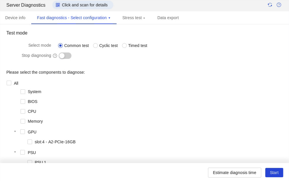
2. Select the modules to test in Please select the components to diagnose. For more information about diagnostic items corresponding to the components, see H3C Servers iFIST User Guide.
3. (Optional.) Select the test mode. Options are Common test, Cyclic test, and Timed test.
¡ To use the common test mode, complete all test items in sequence.
¡ To use the cyclic test mode, set the number of test cycles in the Cycles field.
¡ To use the timed test mode, set the test duration in minutes in the Time field.
4. (Optional.) Select the Stop diagnosing option to stop diagnosing when the first diagnosis error occurs.
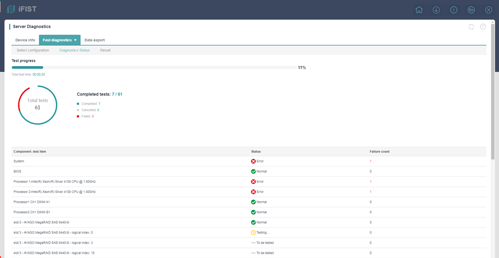
5. Click Start to start fast diagnostics.
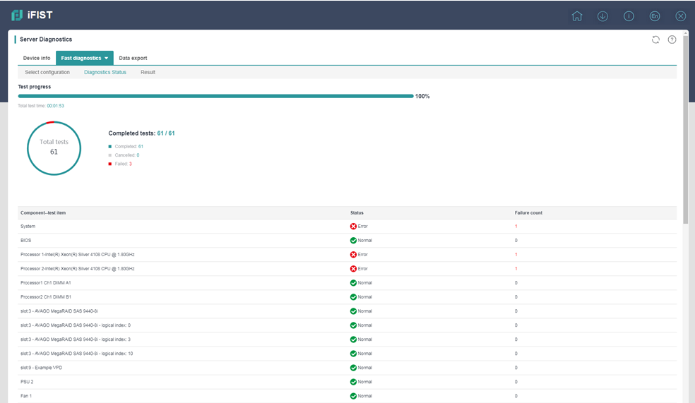
iFIST opens the Diagnostic status page upon start of the diagnostic process, as shown in Figure 26. The page provides information about the ongoing diagnostic tests, including the test progress, summarized test statistics, and module-specific test results.
Figure 26 Diagnostic status page
6. After the fast diagnostic process is completed, click Result to view the diagnostic results.
The Result tab displays the test result for each component, and provides the failure reason and recommended fixes if the test result is Error, as shown in Figure 27.
Figure 27 Result tab
Performing stress tests
1. Select Stress test > Select configuration.
Figure 28 Configuring stress test settings
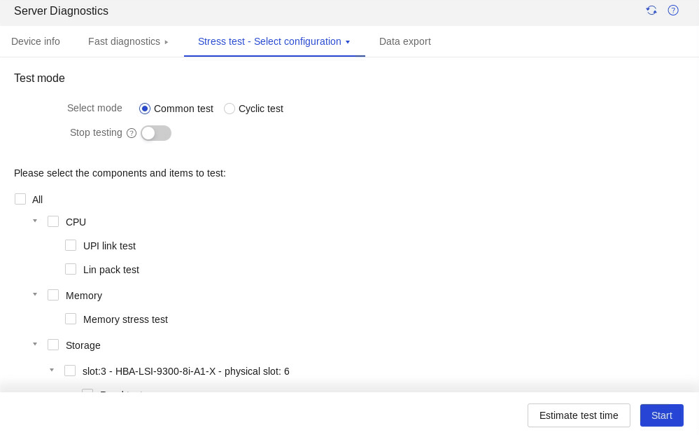
2. Select the tests you want to run for each component in Please select the components and items to test. For more information about diagnostic items corresponding to the components, see H3C Servers iFIST User Guide.
3. (Optional.) Select the test mode. Options are Common test and Cyclic test.
To use the cyclic test mode, set the number of test cycles in the Cycles field.
4. (Optional.) Select Automatically stop the test when an error first occurs in the test results.
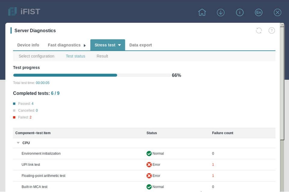
5. Click Start to start the stress test.
The Test status page opens, displaying information about the overall test progress, ongoing information summary, and the test status of the selected components.
Figure 29 Test status
6. (Optional.) To abort the testing process, click Cancel.
7. (Optional.) After the selected stress tests are completed, click Restart to run the tests again, if needed.
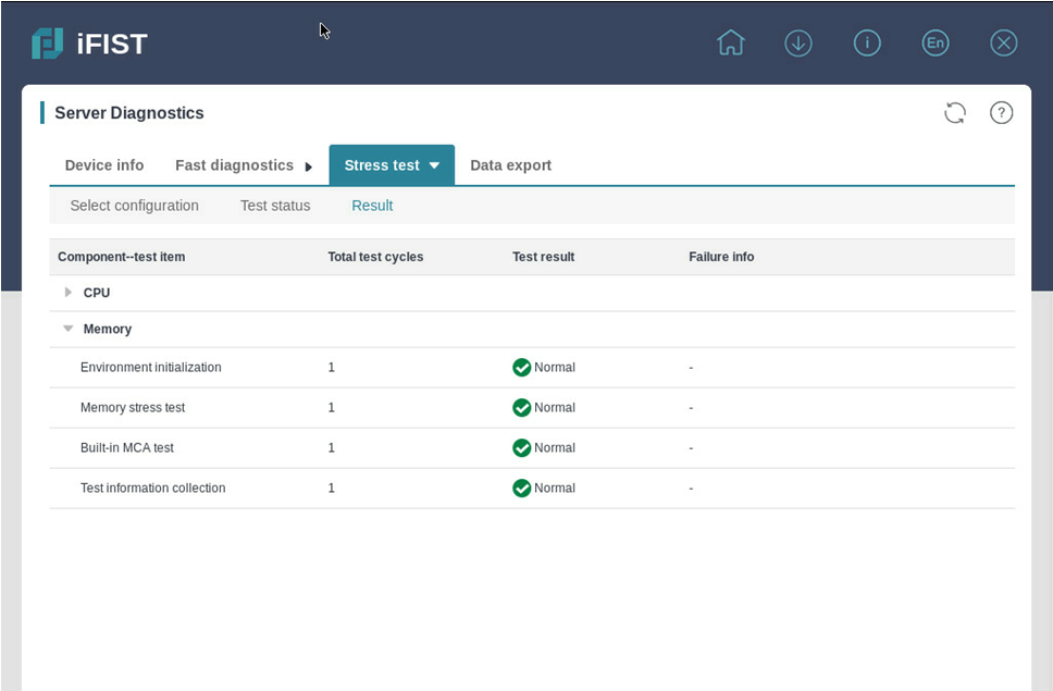
8. To view the test results, click Result. The Result tab displays the test result for each component, total test count, test results, and provides the failure reason if the test result is Error, as shown in Figure 30.
Exporting data
1. Click Intelligent Diagnostics, and select Server Diagnostics.
2. Click the Data export tab.
The Data Export tab opens, as shown in Figure 31.
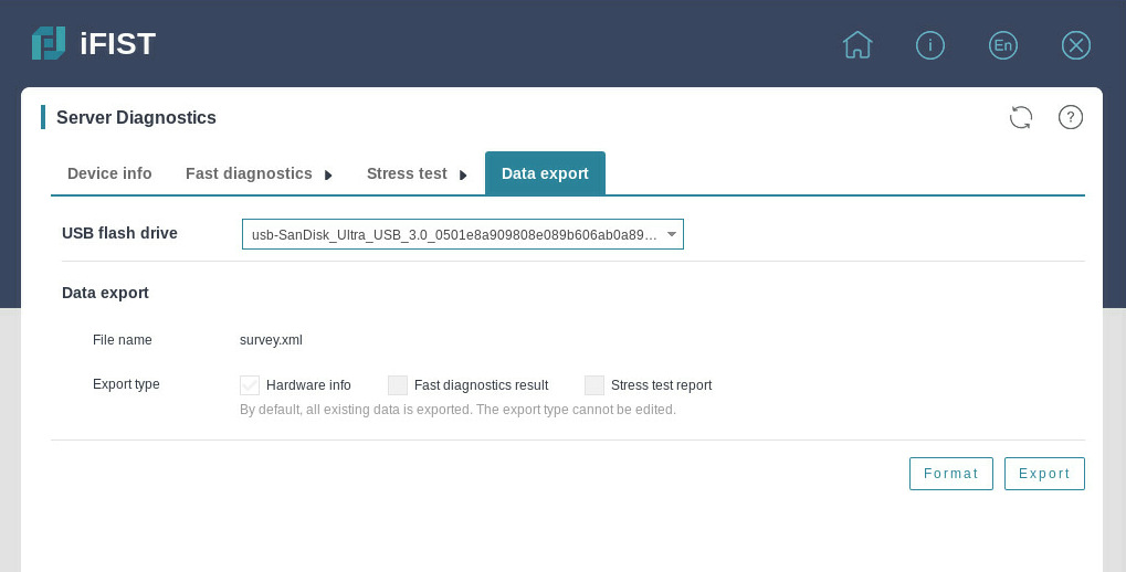
3. From the USB flash drive list, select the USB flash drive to which you want to export the server diagnostics data, and then click Format to format it by using the FAT32 file system.
Format the USB flash drive with caution. This operation deletes data in the USB flash drive.
4. Click Export.
Memory smart-test
About this feature
The memory smart-test feature tests the memory in the POST memory initialization stage through the memory test tool embedded in the BIOS. In the current software version, only the Hynix, Samsung, and Micron memory chips are supported. After the test, you can view the test result on the iFIST.
Application scenarios
· The test is conducted in BIOS UEFI mode.
· Only the Hynix, Samsung, and Micron memory chips are supported.
Overview
The procedure of memory smart-test is as shown in Figure 32.
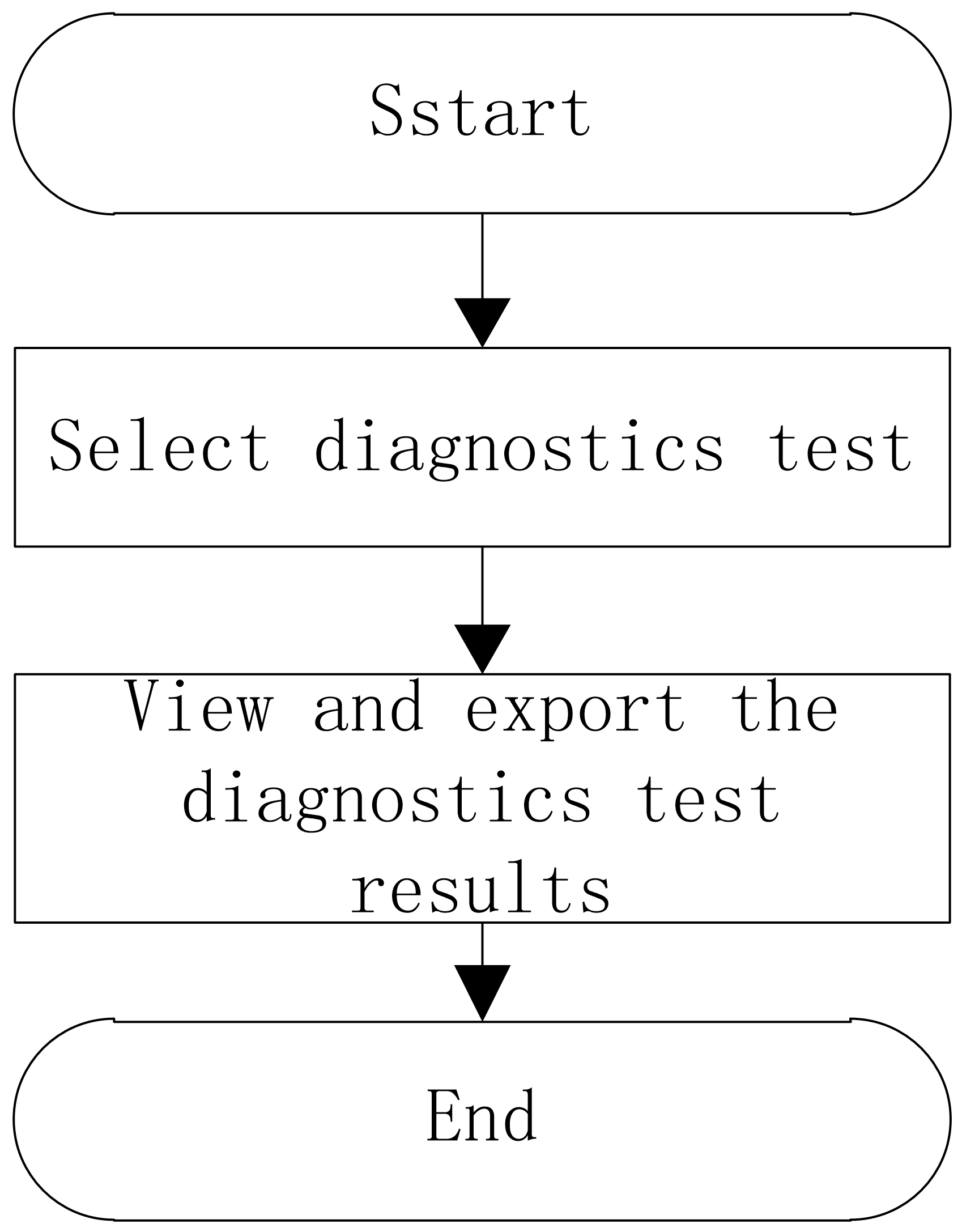
Table 9 Overview of memory Smart-Test configuration
|
Configuration tasks |
Description |
|
Select parameters such as types of diagnostics. |
|
|
Select device to view test results. |
Restrictions and guidelines
· In the current software version, the diagnostics test result can be exported to a USB flash drive formatted by using the FAT32 or NTFS file system.
· Select the test and repair policy with caution. If you perform a test after repairing, no errors can be tested.
· After the test is started, do not manually reboot the server. The server will be automatically rebooted by the diagnostics test program.
· Only some servers and BIOSs of the specific versions support the memory test feature. For more information, see the H3C Servers iFIST User Guide.
Selecting diagnostics test
1. Click Intelligent Diagnostics, and select Memory Smart-Test to enter the page as shown in Figure 33.
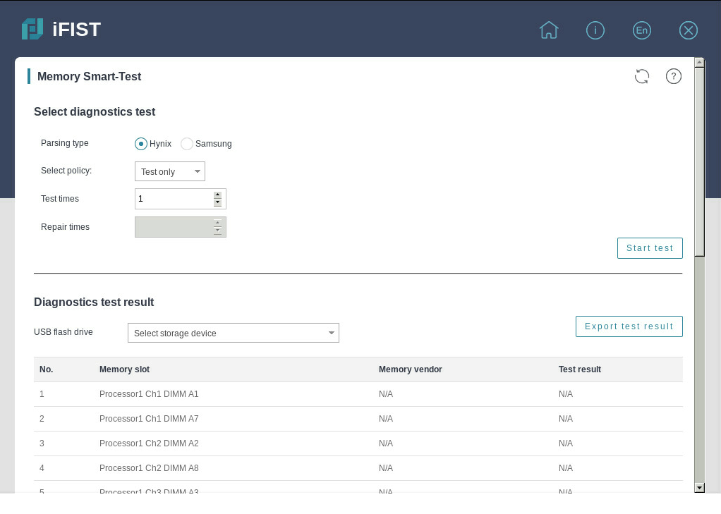
2. Configure the test parameters. For more information about parameters, see the H3C Servers iFIST User Guide.
3. Click Start test. The diagnostics test will start after the server is cold rebooted.
Viewing and exporting the diagnostics test result
1. Click Server Diagnostics, and select Memory Smart-Test.
2. View the diagnostics test result on the page as shown in Figure 34.
Figure 34 Diagnostics test result
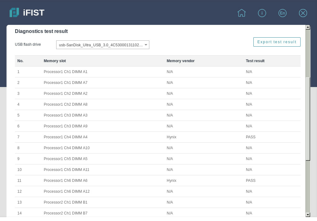
3. Select a storage device, and click Export test result to download the test result to the iFIST/SmartTest directory in the root directory of the USB flash drive.
4. Test result: Result of the smart-test, as shown in Table 10, Table 11, and Table 12. This field displays N/A when the test is not finished, the memory chip is corrupted, or the memory chip is absent.
|
Test result |
Remarks |
|
Training Failure |
Memory training failed. |
|
Pass |
The memory passed the test. |
|
Fail (PPR Disable) |
Errors occurred to the memory chip. |
|
Fail (PPR Pass) |
Errors occurred to the memory chip, and the memory chip was repaired successfully. |
|
Fail (PPR Fail) |
Errors occurred to the memory chip, and the memory chip failed to be repaired. |
|
Temp. Overflow |
The memory chip temperature was too high, and the memory test was skipped. |
|
Error Overflow |
Errors overflew, and the total number of errors exceeded the maximum number of errors supported (a single DIMM can repair up to 32 errors) . |
|
Test result |
Remarks |
|
Pass |
The memory passed the test. |
|
Fail |
Errors occurred to the memory chip. |
|
Non-fixable Fail |
Errors overflew, and the total number of errors exceeded the maximum number of errors supported (a single DIMM can repair up to 10 errors) . |
|
SKIP |
Memory training failed, or the current memory chip is not a Hynix one. |
|
REPAIRED |
Errors occurred to the memory chip, and the memory chip was repaired successfully. |
|
Test result |
Remarks |
|
No issues found |
Memory training failed or the memory passed the test |
|
PPR Disabled |
Errors occurred to the memory chip, and only the test was performed |
|
PPR Success |
Errors occurred to the memory chip, and the memory chip was repaired successfully |
|
PPR Failure |
Errors occurred to the memory chip, and the memory chip failed to be repaired |
|
PPR Inprogress |
Errors occurred to the memory chip, the repair function was not started, and the memory chip was to be repaired. |
|
PPR Limit Exceeded |
Errors overflew, and the total number of errors exceeded the maximum number of errors supported (a single DIMM can repair up to 4 errors, and a single socket can repair up to 48 errors) |
|
DIMM Configuration not supported |
The memory chip does not support this test. |
Configuration management
About this feature
The configuration management function of iFIST supports the import and export of HDM, BIOS, and RAID configuration files.
Application scenarios
You can apply the same configuration to a batch of servers to facilitate the deployment.
Overview
The procedure of configuration management is as shown in Figure 35.
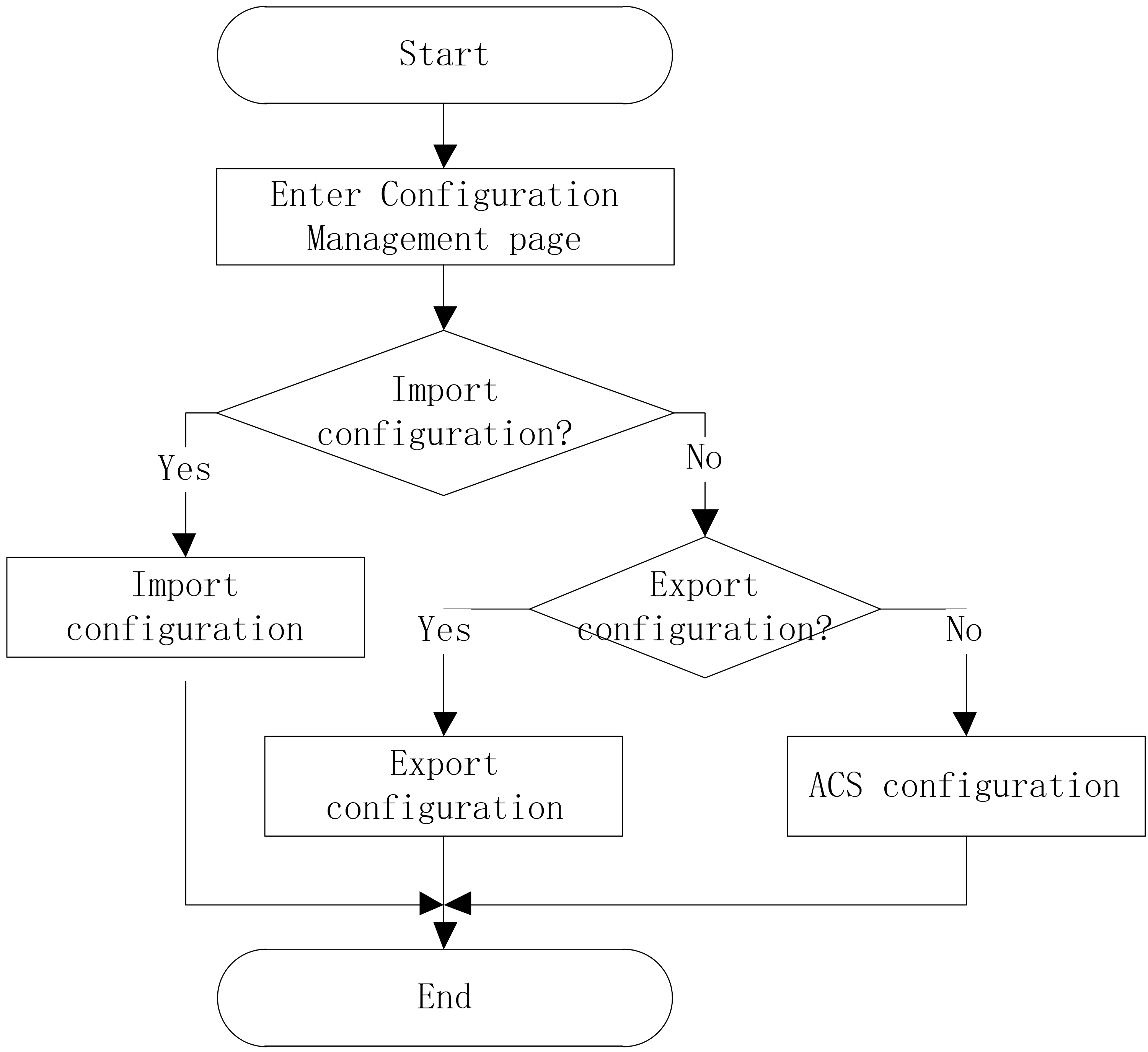
Table 13 Overview of memory Smart-Test configuration
|
Configuration tasks |
Description |
|
Importing configuration |
Import the configuration files from the USB drive into the system or the selected control card. |
|
Exporting configuration |
Export the profile to a USB drive as a file. |
|
Configuring ACS |
Operate on ACS configuration. |
Restrictions and guidelines
Restrictions and guidelines of configuration management
· In the current software version, only USB flash drives formatted by using the FAT32 or NTFS file system support importing and exporting configurations.
· PMC storage controllers do not support importing and exporting RAID configuration.
· The configuration management function needs to cooperate with HDM software. Only HDM-1.11.25 and later support configuration management.
· Support for ACS configuration varies by device model. For more information, see the GUI.
· To configure ACS capability, you must use the HDM software. For more information, see the iFIST release notes.
· To configure ACS control, you must use the BIOS software. For more information, see the iFIST release notes.
Restrictions and guidelines of importing configuration
· Before importing RAID and BIOS configurations, make sure the device model and component configuration (for example, storage controller model, disk count, and slots) are the same. When importing RAID configuration, make sure the storage controller operates in RAID mode.
· Before importing HDM configuration, make sure the device model is the same. First delete the comment statements for the user configuration information in the configuration file, and then modify the user password into a plaintext password.
· To import configuration successfully, make sure the bonding mode in the configuration file is the same as the bonding mode of the device before importing HDM configuration.
· Before importing the RAID configuration, if the old RAID information of the disks is not cleared, the RAID configuration will be marked as foreign configuration. As a result, the RAID configuration will fail. Please first clear the RAID configuration of the disks in the BIOS.
· Before importing HDM configuration, if a configuration item is deleted or does not exist in the configuration file, the configuration item remains as it was after the configuration is imported.
· Modify the configuration file with caution, and make sure the configuration information after modification is valid. Otherwise, the configuration file might fail to be imported.
· When you import controller attributes, the system checks the controller model and working mode. The supported controller attributes vary by controller model as follows:
¡ For H460 and P460 controllers, the Configured Drives, Unconfigured Drives, and HBA Drives attributes for global cache setting are supported.
¡ For P460 controllers, the Read cache ratio and Write cache ratio attributes are supported.
¡ For LSI controllers, the supported attributes include:
- maintainPdFailHistory—Maintains history failure records for physical drivers. Options include ON and OFF.
- copyback, including smartSsdCopyback for SSD drivers and smartHddCopyback for HDD drivers.
Restrictions and guidelines of exporting configuration
· Before exporting RAID configuration, make sure the storage controller has been initialized.
· Before exporting RAID configuration, make sure logical drives of the RAID controller are in normal state, and no scaling, migration, rebuilding, or erasing operations are performed.
· When you export controller attributes, the system checks the controller model and working mode. The supported controller attributes vary by controller model as follows:
¡ For H460 and P460 controllers, the Configured Drives, Unconfigured Drives, and HBA Drives attributes for global cache setting are supported.
¡ For P460 controllers, the Read cache ratio and Write cache ratio attributes are supported.
¡ For LSI controllers, the supported attributes include:
- maintainPdFailHistory—Maintains history failure records for physical drivers. Options include ON and OFF.
- copyback, including smartSsdCopyback for SSD drivers and smartHddCopyback for HDD drivers.
Procedure
1. Click Configuration Management to enter the configuration management page.
2. Select the type of the configuration to be imported or exported.
3. Select a storage device, and then select a configuration file in the storage device, as shown in Figure 36.
Figure 36 Importing configuration
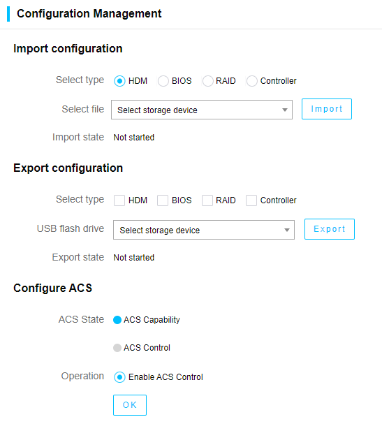
4. Click Import or Export.
Precautions
· After the HDM configuration is imported successfully, HDM might automatically restart to make the configuration take effect.
· After the BIOS configuration is imported successfully, you must restart the server to make the configuration take effect.
· After the RAID configuration is imported successfully, the configuration takes effect about 40 seconds later.
· During the configuration import process, do not power off the server. Otherwise, some functions of iFIST might fail.
· When you import HDM, BIOS, RAID, or controller configuration, if the Web interface prompts that an entry fails to be imported, the import is paused. In this case, you must modify the entry that fails to be imported, and import the configuration again. Repeat this step until the import is finished.
· The imported RAID configuration does not contain configuration of the RAID controller itself (for example, RAID controller mode).
· To ensure successful configuration import, do not perform any configuration management operations on the HDM Web interface during the configuration import process.
· To avoid import failure, make sure the controller model (model) and the controller mode (mode) in the configuration file are the same as the target controller. For example, an import operation will fail if a configuration file is exported in Mixed mode, and then is imported in HBA mode.
· The exported RAID configuration does not contain configuration of the RAID controller itself (for example, RAID controller mode).
· To export configuration successfully, do not perform any configuration management operations on the HDM Web interface during the configuration export process.
· When you export the controller configuration, only the controller attributes can be exported and the RAID configuration cannot be exported.
Configuring ACS
Restrictions and guidelines
· Before configuring ACS, make sure all PCIe switch cards are in place.
· You cannot disable the ACS capability attribute.
Procedure
1. Click the Configuration Management icon to enter the configuration management page.
2. Select an operation. In the dialog box that opens, click OK. The selected operation takes effect after the server is cold rebooted.
Figure 37 Configuring ACS
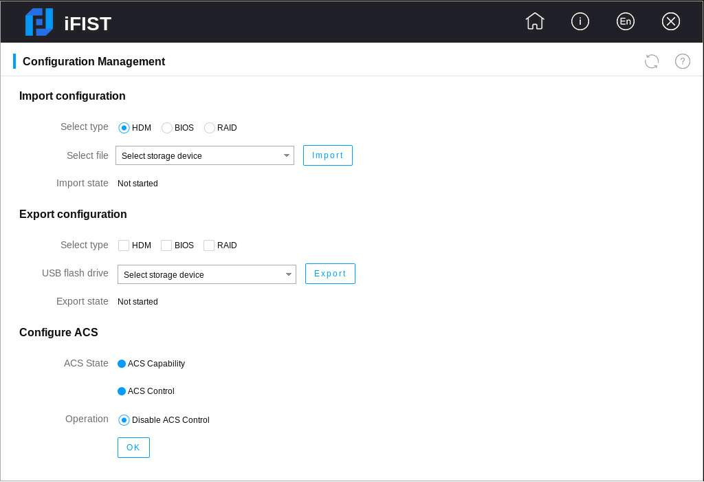
3. When the ACS capability attribute is not enabled, you can enable only ACS capability or enable both ACS capability and ACS control.
4. When the ACS capability attribute is enabled, you can disable the ACS control attribute if the ACS control attribute is enabled, and you can enable the ACS control attribute if the ACS control attribute is disabled or not enabled.
Download logs
About this feature
Use this function to download OS logs, SDS logs, system operation logs, and specific components. The system saves the downloaded logs and information to the iFIST/LogDownloadUniTool/LogDownload directory of a USB flash drive inserted into the server.
Application scenarios
Operations personnel gather various log information to analyze specific issues when investigating faults that occur during server operation.
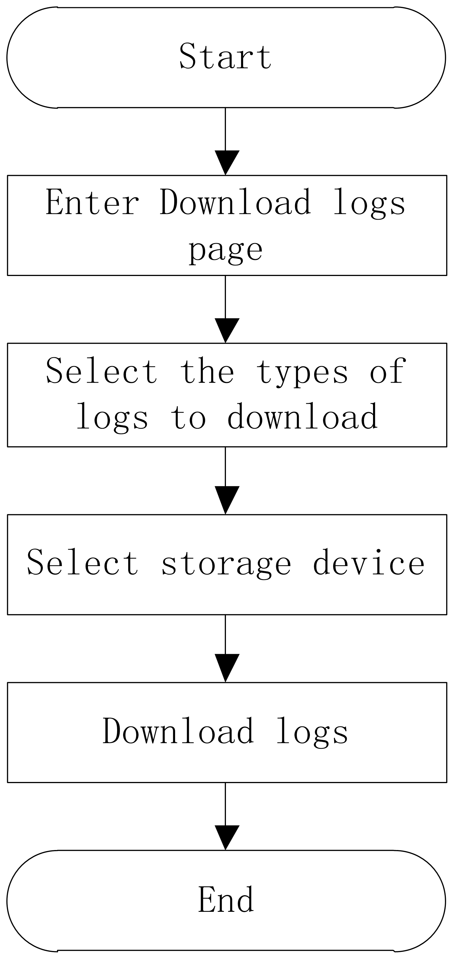
Overview
The procedure of downloading log is as shown in Figure 38.
Restrictions and guidelines
· You can download logs to a USB flash drive formatted with the FAT32 or NTFS file system.
· In the current software version, only logs of hard disks of the following vendors can be downloaded: Seagate, Hitachi, Toshiba, Samsung, Intel, Micron, Kioxia, Memblaze, DERA, SSSTC, Union Memory, DapuStor, YMTC, DTmoblie, Mega Electronics Co., Hynix, ScaleFlux, Longsys, and Solidigm, LTD..
Procedure
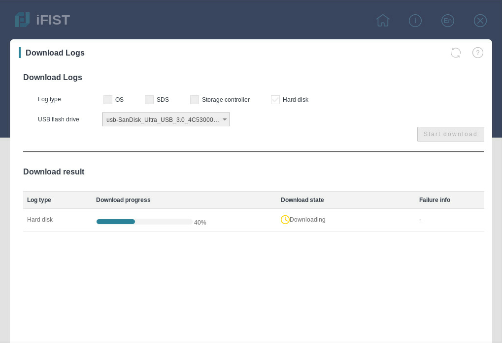
1. Click Download Logs to enter the page as shown in Figure 39.
2. Select the types of logs to download.
3. Select the target USB flash drive.
4. Click Start download.
Figure 39 Downloading logs (for example, hard disk logs)
Precautions
· The log download function needs to cooperate with HDM software. Only HDM-1.11.19 and later support downloading SDS logs.
· To download logs successfully, make sure you have not one-click collected information on the HDM Web interface before downloading logs.
· The component SN information for the server collects only information about the system board, processors, memory, drives, power supplies, and PCIe modules (NIC, FC HBA, GPU, and RAID).
· When you download the SMART information for an LSI storage controller, make sure the storage controller has a minimum of one logical drive or a passthrough physical drive.
· For the HBA-LSI-9311-8i-A1-X card, you can download SMART information for only passthrough physical drives.
Firmware update
About this feature
After you mount a REPO image file through a CD (physical CD or HDM virtual media) or USB flash drive, you can use this function to update various firmware products for the server at the same time, including HDM, BIOS, various CPLDs, storage controller firmware, NIC firmware, and hard disk firmware.
Application scenarios
Some server components require function upgrades or bug fixes to.
Overview
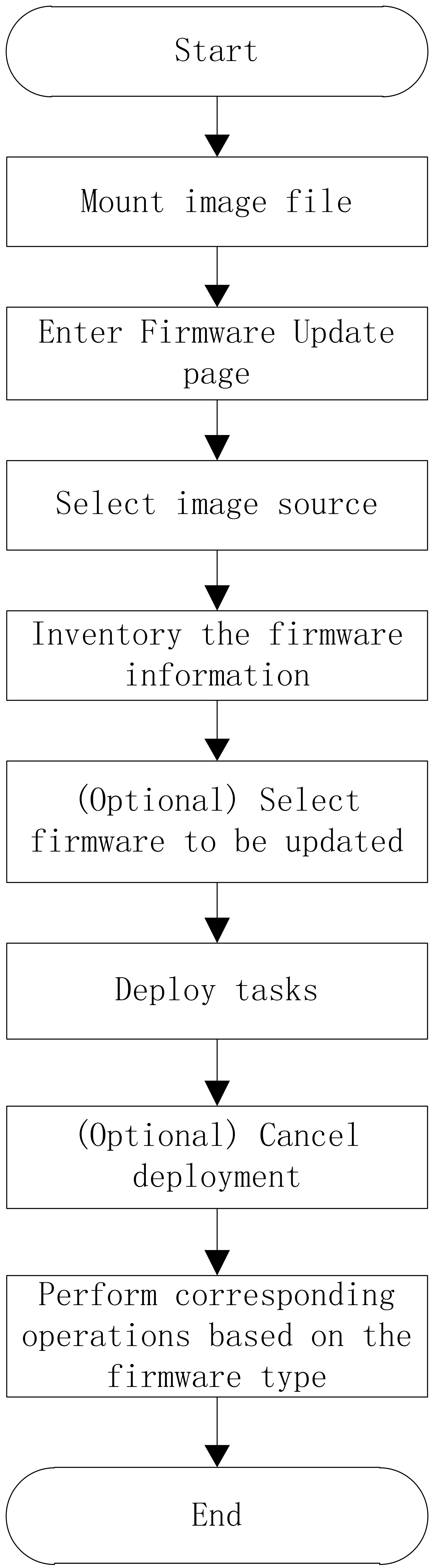
The procedure of firmware update is as shown in Figure 40.
Restrictions and guidelines
· In the current software version, USB flash drive partitions formatted by using the FAT32, EXT2/3/4, or NTFS file system can be used to mount a REPO image file. A REPO image file name supports only letters, digits, dots (.), hyphens (-), and underscores (_), and cannot exceed 64 characters (including the file extension).
· The name of the USB flash drive path where the REPO image file resides cannot exceed 64 characters.
Procedure
1. Mount a REPO image file with one of the following method:
¡ Mount the REPO image file through a CD.
¡ Mount the REPO image file through the USB flash drive. Connect the USB flash drive where the REPO image files resides to the USB connector on the server.
2. Click Firmware Update to enter the firmware update page.
Figure 41 Firmware Update page
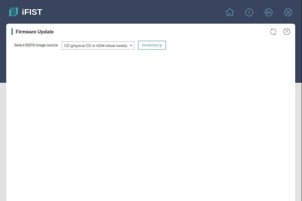
3. From the Select REPO image source list, select an image source. Options include CD and USB flash drive. If you select USB flash drive, you can select the target REPO image file from the level-2 list.
4. Click Inventory to start inventorying the firmware information in the REPO image file. To cancel an inventorying task in progress, click Stop inventorying.
5. After inventorying is completed, firmware products with the target versions later than the current versions are automatically selected. Alternatively, you can manually select the firmware products to be updated.
Figure 42 Inventorying task completed
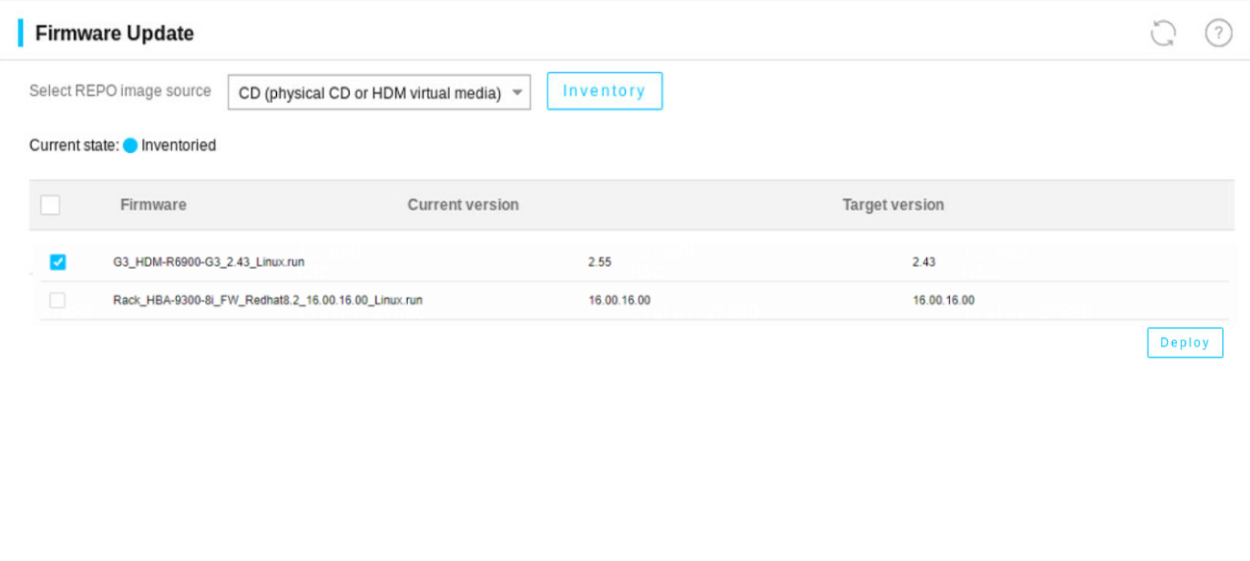
6. Click Deploy in the lower right corner to start updating the firmware products. To cancel a deployment task in progress, click Stop deployment.
7. After the firmware products are updated, different firmware products take effect in different ways, as shown in Table 14.
Table 14 Firmware effective ways
|
Firmware type |
Effective way |
|
HDM |
Restart the HDM. For more information, see H3C Servers HDM User Guide. |
|
BIOS |
Restart the server. To restart the
server, click |
|
CPLDs |
Different CPLDs take effect in different ways. For more information, see the firmware update guide. |
|
Storage controller firmware NIC firmware Hard disk firmware |
Restart the server. To restart the
server, click |
Prerequisites
· You cannot switch the page when an inventorying task or deployment task is in progress. To switch the page, you must first cancel the task in progress or wait until the current task is completed. After you switch to another page, the inventorying task or deployment task information on the firmware update page will be cleared.
· After you click Stop inventorying or Stop deployment, the inventorying or deployment task will be stopped until inventorying or deployment is completed on the current firmware.
· After the firmware is updated, do not perform other operations until the new firmware takes effect. Otherwise, the functions might be abnormal.
Secure data clearing
About this feature
The secure data clearing technology of iFIST supports restoring the HDM configuration to factory defaults, restoring the BIOS configuration to factory defaults, deleting the BIOS password, clearing data in NVDIMM, deleting logical drives, clearing data on drives, and clearing data on the server's SD module.
Application scenarios
When a server stops running for the end of lifecycle or other reasons, you can use the secure data clearing function to clear the HDM, BIOS, and storage data saved in the server to avoid user data breach.
Overview
The procedure of secure data clearing is as shown in Figure 43.
Restrictions and guidelines
· Before clearing data, make sure all external storage devices (including but not limited to external hard drives) of the server have been removed to avoid clearing data by mistake.
· During the data clearing process, do not reboot the server, reboot HDM, or modify the operating system configuration.
Procedure
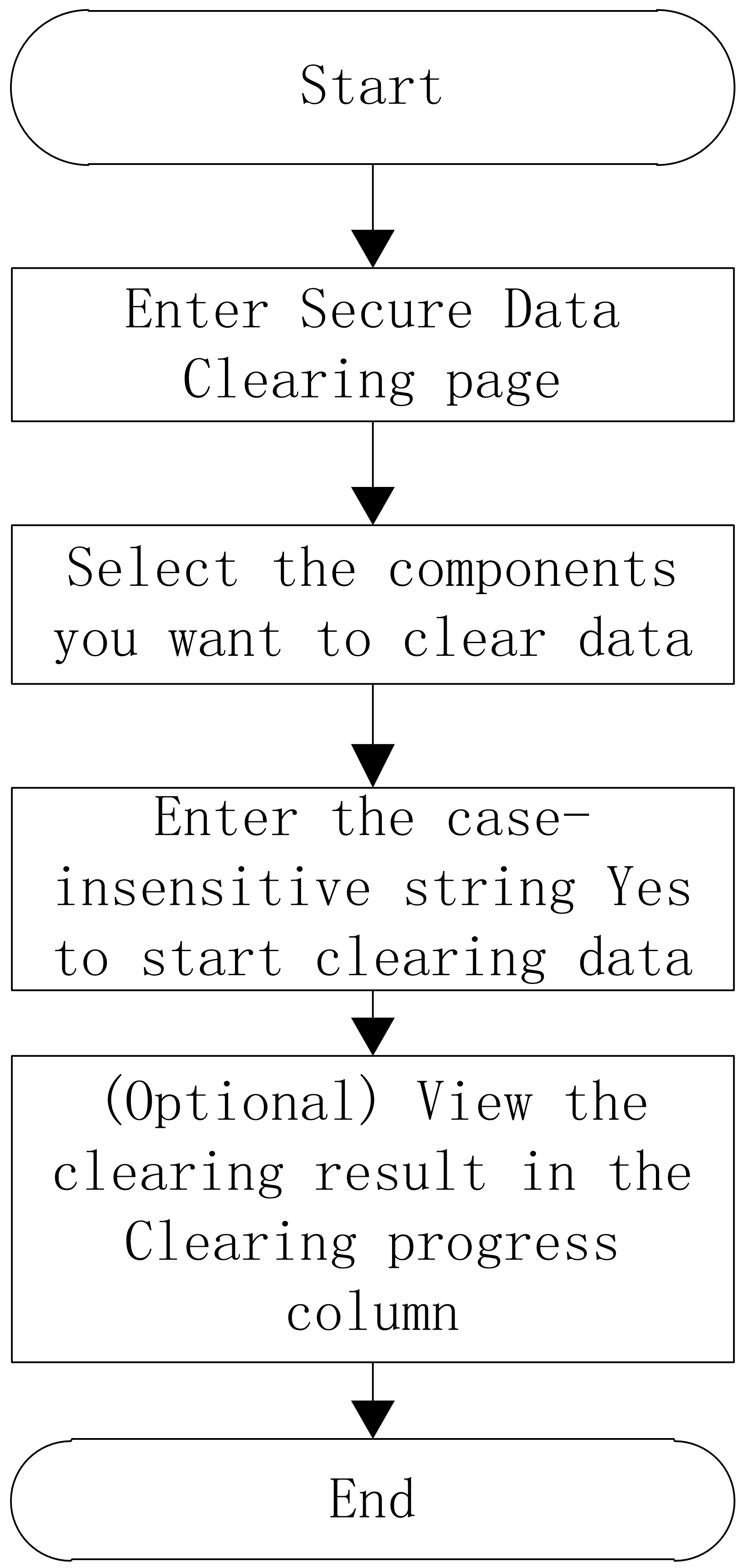
1. Click Secure Data Clearing.
Figure 44 Secure Data Clearing page
2. On the Component list tab, select the components for which you want to clear data, including HDM, BIOS, and storage. Figure 45 shows the influence of the secure data clearing function on each component.
3. Click OK. In the dialog box that opens, enter the case-insensitive string YES to start clearing data. The system switches to the Clearing progress tab automatically.
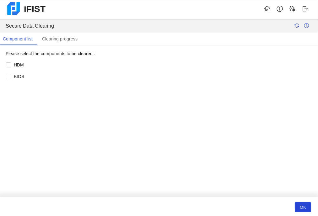
4. After data clearing is finished, you can view the clearing result in the Clearing progress column, as shown in Figure 45.
Figure 45 Viewing the clearing progress
Supplements
The influence of the secure data clearing function is shown in Table 15.
Table 15 Influence of the secure data clearing function
|
Component name |
Influence |
|
HDM |
Restore HDM to default configuration |
|
BIOS |
· Restore the BIOS to default configuration · The administrator and user passwords are cleared on the BIOS side. When the server is rebooted next time, a user whose password is cleared can enter the BIOS Setup directly without entering a password. |
|
No-volatile DRAM (NVDIMM) |
All data in non-memory mode is cleared, and the NVDIMM changes to the full memory mode. |
|
Storage controller |
· All logical drives of RSTe and VROC storage controllers are deleted. · Logical drives of the following PMC storage controllers are all deleted: ¡ HBA-H460-M1, HBA-H460-B1 ¡ RAID-P460-M2, RAID-P460-B2, RAID-P460-M4, RAID-P460-B4 ¡ RAID-P4408-Mf-8i ¡ RAID-P4408-Mr-8i ¡ RAID-P2404-Mf-4i · Logical drives of the following LSI storage controllers are all deleted. If an LSI storage controller is in RAID mode before the logical drives are deleted, the JBOD attribute of the RAID mode becomes ON after the logical drives are deleted. ¡ RAID-LSI-9361-8i(1G)-A1-X. ¡ RAID-LSI-9361-8i(2G)-1-X. ¡ RAID-LSI-9560-LP-8i(4G) ¡ RAID-LSI-9560-LP-16i(8G) ¡ HBA-LSI-9500-LP-8i ¡ HBA-LSI-9500-LP-16i ¡ HBA-LSI-9540-LP-8i ¡ HBA-LSI-9311-8i ¡ HBA-LSI-9300-8i · Logical drives on the RAID-MARVELL-SANTACRUZ-LP-2i are all deleted. |
|
Hard drive |
Data in all hard drives is cleared |
|
SD card |
Data in all SD cards is cleared |
Prerequisites
· The secure data clearing function can clear only data in physical drives that can be recognized by the operating system. If a physical drive cannot be recognized by the operating system for damage or other reasons, data in the physical drive cannot be cleared.
· To clear data of storage-related components again after you clear data of storage-related components, you must restart iFIST.
· If data in a hard drive fails to be cleared during the data clearing process, you can try to clear data in the hard drive in other methods.
Updating iFIST
Procedure
1. Download the most recent iFIST image file from the H3C website to a storage media.
2. Mount the storage media to the server. The storage media now only supports a physical drive or a virtual CD. Make sure the server has only one bootable media mounted. If the server has multiple bootable media mounted, the server might fail to locate the correct boot media and upgrade of iFIST will fail as a result.
3. Select an upgrade option and start the upgrade process.
4. Reboot the server after the upgrade is complete.
5. Verify that iFIST is successfully upgraded.
Example: Updating iFIST on a server in UEFI boot mode
1. Sign in to HDM.
2. Mount the iFIST image file to the HDM remote console. This example uses an image file stored on a virtual CD.
a. On the HDM Web interface, navigate to the Remote Control > Remote Console page, as shown in Figure 46.
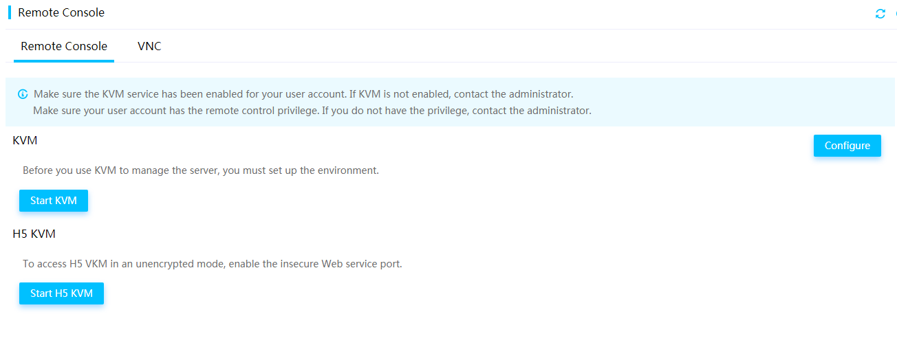
b. Click HDMM to launch the HDM remote console.
c. Select Media > Virtual Media Wizard from the top menu bar.
The Virtual Media window opens and displays the CD/DVD tab by default, as shown in Figure 47.
Figure 47 Virtual Media window
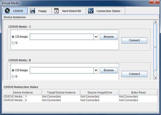
a. Click Browse next to a CD Image field to select the iFIST image file, and then click Open.
b. Click Connect.
3. Reboot the server.
The POST screen opens upon completion of the server initialization, click ESC or DEL to enter BIOS Setup page as shown in Figure 48.
Figure 48 POST screen (BIOS version 2.00.26)
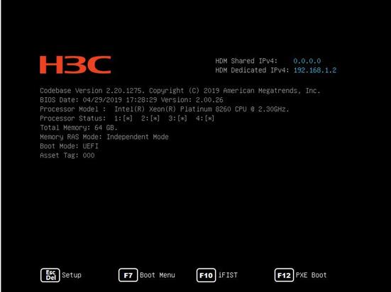
4. Select the Sava & Exit menu, as shown in Figure 49.
Figure 49 BIOS setup screen
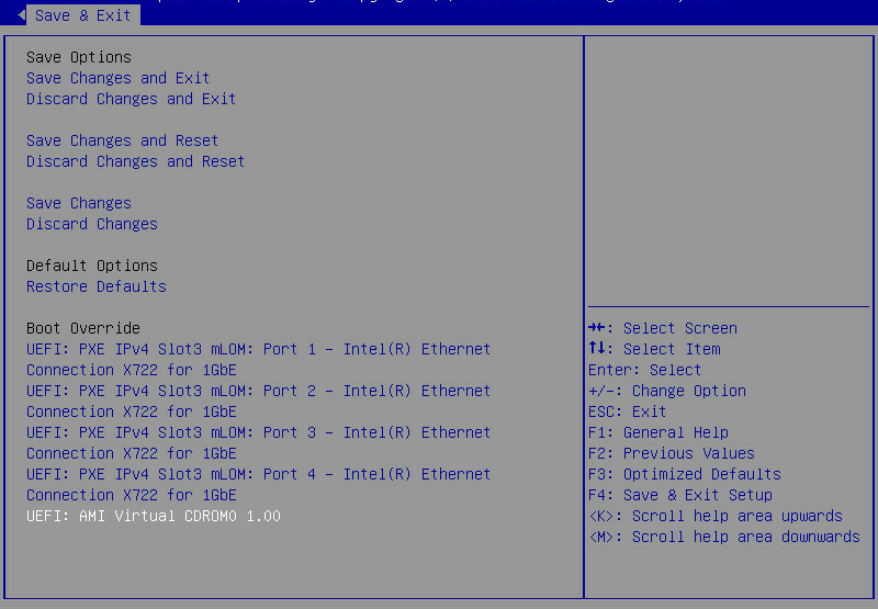
5. Select UEFI:AMI Virtual CDROM0 1.00 and press Enter.
The system starts to upgrade iFIST, as shown in Figure 50.
Figure 50 Upgrading iFIST
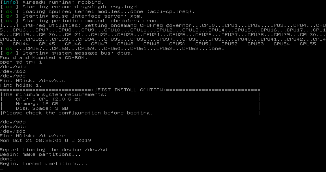
|
|
IMPORTANT: Do not remove the boot media during the upgrade process. If the boot media is removed before the upgrade completes, you must re-attach the boot media to the server, reboot the server, and restart the upgrade process. |
6. After the upgrade is complete, type yes and press Enter at the system prompt.
Figure 51 Completing iFIST upgrade
The system automatically ejects the installation media and displays a prompt, as shown in Figure 52.
Figure 52 Removing the installation media at the system prompt
7. Press Enter to reboot the server.
8. Launch iFIST.
9. On the Web interface of iFIST, and click ![]() in the
upper right corner to check the
iFIST version and verify that iFIST is upgraded successfully.
in the
upper right corner to check the
iFIST version and verify that iFIST is upgraded successfully.
FAQ
iFIST becomes unavailable after HDM is reset. How do I resolve the issue?
As a best practice, do not reset HDM while you are using iFIST. If you did so, reboot the server and then restart iFIST.
A logical drive is displayed with a garbled name in iFIST. How do I resolve the issue?
Delete the logical drive with the garbled name, and then create a new logical drive as needed.
When upgrading iFIST on a server that uses a USB flash drive as the boot device, iFIST got stuck on the GRUB page. How do I resolve the issue?
Remove the USB flash drive that contains the startup configuration file from the server, and then restart the iFIST upgrade process.
As a best practice, do not mount the ISO image and install a USB flash drive as the boot device at the same time.
The iFIST system installation module cannot detect the USB partition that does not have a UUID. How do I resolve the issue?
Reformat the USB partition or replace the USB flash drive with a new one.
iFIST cannot install the operating system on a RAID array created on the onboard RAID controller. Why?
The OS installation cannot be completed because iFIST cannot identify the drive letter of the RAID array created on the onboard RAID controller.
When installing the operating system, I choose to import configuration parameters from a file stored on a USB flash device. However, after waiting for a long time, the browser displays an unresponsive script warning message. How do I resolve the issue?
This symptom might occur if the USB flash drive used for the import contains a lot of files. As a result, the system to display an unresponsive script warning message when loading pages. Just click Continue to proceed.
As a best practice to improve user experience, avoid using a USB flash drive that contains a large number of files for configuration import to iFIST.
When the message "The firmware is being updated in an out-of-band manner from HDM. No operation is allowed. The system will restart automatically after the update. " pops up, how do I resolve the issue?
iFIST is not available because it is cooperating with HDM to update the firmware. After the update is complete, the servers will automatically restart according to the configuration of the system boot options. To access iFIST again, press F10 during the BIOS POST phase.
