- Table of Contents
- Related Documents
-
| Title | Size | Download |
|---|---|---|
| 01-gRPC configuration | 418.05 KB |
Contents
Telemetry technology based on gRPC
Telemetry data model architectures
Restrictions: Hardware compatibility with gRPC
Restrictions and guidelines: gRPC configuration
gRPC configuration tasks at a glance
Configuring the gRPC dial-in mode
Enabling gRPC logging in dial-in mode
Configuring the gRPC dial-out mode
Enabling gRPC logging in dial-out mode
Specifying the PKI domain for secure communication with collectors
Setting the maximum CPU usage for gRPC
Display and maintenance commands for gRPC
Example: Configuring the gRPC dial-in mode
Example: Configuring event-triggered telemetry in gRPC dial-out mode
Example: Configuring the gRPC dial-out mode
Proto definition files in dial-in mode
Proto definition file in dial-out mode
Obtaining proto definition files
Example: Developing a gRPC collector-side application
Generating the C++ code for the proto definition files
Developing the collector-side application (dial-in mode)
Developing the collector-side application (dial-out mode)
Appendix: Methods and attributes for gNMI operations
Configuring gRPC
About gRPC
gRPC is an open source remote procedure call (RPC) system initially developed at Google. It uses HTTP 2.0 and provides network device configuration and management methods that support multiple programming languages.
gRPC protocol stack layers
Table 1 describes the gRPC protocol stack layers.
Table 1 gRPC protocol stack layers
|
Layer |
Description |
|
Content layer |
Defines the data of the service module. Two peers must notify each other of the data models that they are using. |
|
Protocol buffer encoding layer |
Encodes data by using the protocol buffer code format. |
|
gRPC layer |
Defines the protocol interaction format for remote procedure calls. |
|
HTTP 2.0 layer |
Carries gRPC. |
|
TCP layer |
Provides connection-oriented reliable data links. |
Network architecture
As shown in Figure 1, the gRPC network uses the client/server model. It uses HTTP 2.0 for packet transport.
Figure 1 gRPC network architecture
![]()
The gRPC network uses the following mechanism:
1. The gRPC server listens to connection requests from clients at the gRPC service port.
2. A user runs the gRPC client application to log in to the gRPC server, and uses methods provided in the .proto file to send requests.
3. The gRPC server responds to requests from the gRPC client.
The device can act as the gRPC server or client.
Telemetry technology based on gRPC
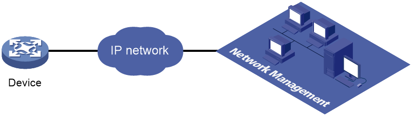
Telemetry is a remote data collection technology for monitoring device performance and operating status. H3C telemetry technology uses gRPC to push data from the device to the collectors on the NMSs. As shown in Figure 2, after a gRPC connection is established between the device and NMSs, the NMSs can subscribe to data of modules on the device.
Figure 2 Telemetry technology based on gRPC
Telemetry modes
The device supports the following telemetry modes:
· Dial-in mode—The device acts as a gRPC server and the collectors act as gRPC clients. A collector initiates a gRPC connection to the device to subscribe to device data.
Dial-in mode supports the following operations:
¡ Get—Obtains device status and settings.
¡ CLI—Executes commands on the device.
¡ gNMI—gRPC Network Management Interface operations, which include the following subtypes of operations:
- gNMI Capabilities—Obtains the capacities of the device.
- gNMI Get—Obtains the status and settings of the device.
- gNMI Set—Deploys settings to the device.
- gNMI Subscribe—Subscribes to data push services provided by the device. The data might be generated by periodical data collection or event-triggered data collection.
· Dial-out mode—The device acts as a gRPC client and the collectors act as gRPC servers. The device initiates gRPC connections to the collectors and pushes device data to the collectors as configured.
Telemetry data model architectures
The device supports the following telemetry data model architectures:
· Three-layer data model architecture—Contains the following three layers:
¡ RPC layer—Defined in public proto definition files grpc_dialout.proto and grpc_dialout_v3.proto. This layer provides public RPC methods such as the message format.
¡ Telemetry layer—Defined in the public proto definition file telemetry.proto. This layer provides data collection-related services.
¡ Content layer—Carries GPB or JSON encoded service data.
The RPC and telemetry layers are identical to the gRPC layer in the gRPC protocol stack.
· Two-layer data model architecture—Contains the RPC and content layers. Two-layer data models support only JSON for service data encoding.
gNMI
gRPC Network Management Interface (gNMI) is a gRPC-based protocol for network device management. It defines a series of RPC methods to obtain or configure the states of devices.
The device supports gNMI and non-gNMI subscriptions for pushing data to a collector.
Protocols
RFC 7540, Hypertext Transfer Protocol version 2 (HTTP/2)
Restrictions: Hardware compatibility with gRPC
gRPC is available only on the S5130S-HI-G switch series.
FIPS compliance
The device supports the FIPS mode that complies with NIST FIPS 140-2 requirements. Support for features, commands, and parameters might differ in FIPS mode and non-FIPS mode. For more information about FIPS mode, see Security Configuration Guide.
gRPC is not supported in FIPS mode.
Restrictions and guidelines: gRPC configuration
Disabling the gRPC service deletes all gRPC-related settings.
If you do not specify the source IP address for packets sent to collectors on the device by using the source-address command, the deviceIpAddr field displays not-config in data pushed to the collectors in dial-out mode.
gRPC configuration tasks at a glance
Configure gRPC dial-in and dial-out modes as needed:
1. Configuring the gRPC dial-in mode
Configure gRPC dial-in when the device acts as a gRPC server to communicate with collectors that act as gRPC clients.
a. Configuring the gRPC service
c. (Optional.) Enabling gRPC logging in dial-in mode
2. Configuring the gRPC dial-out mode
Configure gRPC dial-out when the device acts as a gRPC client to communicate with collectors that act as gRPC servers.
e. (Optional.) Enabling gRPC logging in dial-out mode
3. (Optional.) Specifying the PKI domain for secure communication with collectors
4. (Optional.) Setting the maximum CPU usage for gRPC
Configuring the gRPC dial-in mode
Configuring the gRPC service
1. Enter system view.
system-view
2. Enable the gRPC service.
grpc enable
By default, the gRPC service is disabled.
3. (Optional.) Set the gRPC service port number.
grpc port port-number
By default, the gRPC service port number is 50051.
4. (Optional.) Set the gRPC session idle timeout timer.
grpc idle-timeout minutes
By default, the gRPC session idle timeout timer is 5 minutes.
Configuring a gRPC user
About this task
For gRPC clients to establish gRPC sessions with the device, you must configure local users for the gRPC clients.
Procedure
1. Enter system view.
system-view
2. Add a local user with the device management right.
local-user user-name [ class manage ]
3. Configure a password for the user.
password [ { hash | simple } password ]
By default, no password is configured for a local user. A non-password-protected user can pass authentication after providing the correct username and passing attribute checks.
4. Assign user role network-admin to the user.
authorization-attribute user-role user-role
By default, a local user is assigned the network-operator role.
5. Authorize the user to use the HTTPS service.
service-type https
By default, no service types are authorized to a local user.
For more information about the local-user, password, authorization-attribute, and service-type commands, see AAA configuration in Security Command Reference.
Enabling gRPC logging in dial-in mode
About this task
To identify issues with gRPC in dial-in mode, enable gRPC operations logging in dial-in mode.
This feature generates gRPC operation logs in dial-in mode and sends them to the information center.
With the information center, you can configure log destinations and output rules. For more information about the information center, see Network Management and Monitoring Configuration Guide.
Restrictions and guidelines
gRPC operation logging might degrade device performance if gRPC operations are frequent. As a best practice, use gRPC operation logging only when necessary and log only gRPC operations of interest if gRPC operation logging is enabled.
Procedure
1. Enter system view.
system-view
2. Enable gRPC logging in dial-in mode. Choose the options to configure as needed:
¡ Enable gRPC logging for RPC operations in dial-in mode.
grpc log dial-in rpc { all | { cli | get }* }
By default, gRPC logging is disabled for RPC operations in dial-in mode.
¡ Enable gRPC logging for gNMI operations in dial-in mode.
grpc log dial-in gnmi { all | { capabilities | get | set | subscribe }* }
By default, gRPC logging is enabled for gNMI Set operations and disabled for other gNMI operations in dial-in mode.
Configuring the gRPC dial-out mode
Enabling the gRPC service
1. Enter system view.
system-view
2. Enable the gRPC service.
grpc enable
By default, the gRPC service is disabled.
3. (Optional.) Specify the architecture of telemetry data models.
grpc data-model { 2-layer | 3-layer }
By default, the device uses two-layer telemetry data models to push data.
With the two-layer telemetry data model architecture, the device can only encode pushed data in JSON format.
Configuring sensors
About this task
A sensor is a data path from which the device collects data and then pushes the data to a collector. You can create a sensor group and then specify sensor paths in the group. Sensor groups include non-gNMI sensor groups and gNMI sensor groups. If the collector uses gNMI, you must create gNMI sensor groups.
A sensor path supports either event-trigged or periodic data collection.
· Event-triggered—The device pushes data from the sensor path to the collector when certain events occur. For information about event-triggered sensor paths, see NETCONF XML API Event Reference for the module.
· Periodic—The device pushes data from the sensor path to the collector at intervals. For information about periodic sensor paths, see the NETCONF XML API references for the module except for NETCONF XML API Configuration Reference and NETCONF XML API Data Reference.
· Condition-triggered—The device checks the data of the sensor path periodically and pushes the data from the sensor path to the collector when certain conditions are met. For information about condition-triggered sensor paths, the sensor path check interval, and data push conditions, contact H3C Support.
Condition-triggered sensor paths are supported only by gNMI sensor groups.
Restrictions and guidelines
As a best practice for the device to push data from sensor paths, specify sensor paths of the same type in a sensor group.
Configuring a non-gNMI sensor group
1. Enter system view.
system-view
2. Enter telemetry view.
telemetry
3. Create a non-gNMI sensor group and enter sensor group view.
sensor-group group-name
4. Specify a sensor path.
sensor path path [ selection-nodes node-list ]
To specify multiple sensor paths, execute this command multiple times. If you execute this command multiple times with the same sensor path specified, the most recent configuration takes effect.
Configuring a gNMI sensor group
1. Enter system view.
system-view
2. Enter telemetry view.
telemetry
3. Create a gNMI sensor group and enter sensor group view.
sensor-group group-name gnmi
To enter the view of an existing gNMI sensor group, you do not need to specify the gnmi keyword.
4. Specify a sensor path.
sensor path path [ selection-nodes node-list ]
To specify multiple sensor paths, execute this command multiple times.
Configuring collectors
About this task
Collectors receive sampled data from network devices. For the device to communicate with collectors, you must create a destination group and add collectors to the destination group.
You can add collectors to a destination group by their IP addresses or domain names. When you specify collectors by their domain names, use the following restrictions and guidelines:
· You must configure DNS to make sure the device can translate the domain names of the collectors to IP addresses. For more information about DNS, see Layer 3—IP Services Configuration Guide.
· To view domain name and IP address mappings, use the display dns host command. If a domain name maps to multiple IP addresses, the device will push data to the first reachable IP address.
To encrypt the gRPC connections between the device and the target collector, use one of the following methods:
· Enable TLS encryption globally for all gRPC connections by executing the grpc pki domain command in system view. The device uses the TLS certificates in the specified PKI domain for encryption.
· Enable collector-specific TLS encryption by specifying the tls keyword when you add a collector to a destination group. The device uses one root TLS certificate that came with it to encrypt the gRPC connection to the specified collector.
For a collector, the setting in system view has higher priority than the collector-specific setting.
Restrictions and guidelines
As a best practice, configure a maximum of five destination groups. If you configure too many destination groups, system performance might degrade.
Procedure
1. Enter system view.
system-view
2. Enter telemetry view.
telemetry
3. Create a destination group and enter destination group view.
destination-group group-name
4. Add a collector to the destination group by its IP address.
IPv4:
ipv4-address ipv4-address [ port port-number ] [ tls ]
IPv6:
ipv6-address ipv6-address [ port port-number ] [ tls ]
The IPv6 address cannot be a link-local address. For more information about link-local addresses, see IPv6 basics configuration in Layer 3—IP Services Configuration Guide.
To add multiple collectors, repeat this command. A collector is uniquely identified by a combination of the IP address and port number elements. One collector must have a different element than the other collectors in the destination group.
5. Add a collector to the destination group by its domain name.
IPv4:
domain-name domain-name [ port port-number ] [ tls ]
IPv6:
ipv6 domain-name domain-name [ port port-number ] [ tls ]
To add multiple collectors, repeat this command. A collector is uniquely identified by a combination of the domain name and port number elements. One collector must have a different element than the other collectors in the destination group.
Configuring a subscription
About this task
A subscription binds sensor groups to destination groups. Then, the device pushes data from the specified sensors to the collectors in the destination groups.
Subscriptions include non-gNMI subscriptions and gNMI subscriptions. To push data to a collector that uses gNMI, you must configure a gNMI subscription.
Restrictions and guidelines
For a non-gNMI subscription, specify non-gNMI sensor groups.
For a gNMI subscription, specify gNMI sensor groups.
You cannot use a destination group in both a gRPC subscription and a gNMI subscription.
For the device to correctly push data from sensor paths in a sensor group, make sure the subscription settings for the sensor paths are compliant with Table 2.
Table 2 Compatibility of sensor path types and subscription settings
|
Sensor path type |
Push mode |
Data push interval |
Data push suppression interval |
|
Periodical |
Default |
Configured |
Not configured |
|
Event-triggered |
Default |
Not configured |
Not configured |
|
Condition-triggered |
Condition-triggered |
Not configured |
Configured |
Configuring a non-gNMI subscription
1. Enter system view.
system-view
2. Enter telemetry view.
telemetry
3. Create a non-gNMI subscription and enter subscription view.
subscription subscription-name
4. (Optional.) Set the DSCP value for packets sent to collectors.
dscp dscp-value
By default, the DSCP value for packets sent to collectors is 0.
A greater DSCP value represents a higher priority.
5. (Optional.) Specify the source IP address for packets sent to collectors.
source-address { ipv4-address | interface interface-type interface-number | ipv6 ipv6-address }
By default, the device uses the primary IPv4 address of the output interface for the route to the collectors as the source address.
Changing the source IP address for packets sent to collectors causes the device to re-establish the connection to the gRPC server.
6. (Optional.) Specify the encoding format for pushed data.
encoding { gpb | json }
By default, the device uses the JSON format to encode pushed data.
The device can use the GPB format to encode pushed data only when it uses three-layer telemetry data models to push data.
7. (Optional.) Enable per-row time-stamping for JSON-encoded subscription data.
json row-timestamp enable
By default, the device time-stamps JSON-encoded subscription data on a per-message basis.
This command is not supported when the device uses the three-layer telemetry data model architecture.
8. Specify a sensor group.
sensor-group group-name [ sample-interval [ msec ] interval | suppress-time suppress-time ]
By default, no sensor groups are specified.
|
Parameter |
Description |
|
sample-interval |
Data push interval. Specify this parameter only for periodic sensor paths. |
|
suppress-time |
Data push suppression interval. Specify this parameter only for condition-triggered sensor paths. |
9. Specify a destination group.
destination-group group-name
By default, no destination groups are specified.
Configuring a gNMI subscription
1. Enter system view.
system-view
2. Enter telemetry view.
telemetry
3. Create a gNMI subscription and enter subscription view.
subscription subscription-name gnmi
To enter the view of an existing gNMI subscription, you do not need to specify the gnmi keyword.
4. (Optional.) Set the data push mode.
push-mode condition-triggered
Perform this step only if a sensor group specified for a subscription contains condition-triggered sensor paths.
By default, the data push mode for a sensor path in a subscription is periodical or event-triggered.
5. (Optional.) Set the DSCP value for packets sent to collectors.
dscp dscp-value
By default, the DSCP value for packets sent to collectors is 0.
A greater DSCP value represents a higher priority.
6. (Optional.) Specify the source IP address for packets sent to collectors.
source-address { ipv4-address | interface interface-type interface-number | ipv6 ipv6-address }
By default, the device uses the primary IPv4 address of the output interface for the route to the collectors as the source address.
Changing the source IP address for packets sent to collectors causes the device to re-establish the connection to the gRPC server.
7. Specify a sensor group.
sensor-group group-name [ sample-interval [ msec ] interval | suppress-time suppress-time ]
By default, no sensor groups are specified.
|
Parameter |
Description |
|
sample-interval |
Data push interval. Specify this parameter only for periodic sensor paths. |
|
suppress-time |
Data push suppression interval. Specify this parameter only for condition-triggered sensor paths. |
8. Specify a destination group.
destination-group group-name
By default, no destination groups are specified.
Enabling gRPC logging in dial-out mode
About this task
To identify issues with gRPC in dial-out mode, enable gRPC data collection logging in dial-out mode.
This feature generates gRPC data collection logs in dial-out mode and sends them to the information center.
With the information center, you can configure log destinations and output rules. For more information about the information center, see Network Management and Monitoring Configuration Guide.
Restrictions and guidelines
gRPC logging in dial-out mode is unavailable for gNMI subscriptions.
Procedure
1. Enter system view.
system-view
2. Enable gRPC logging in dial-out mode.
grpc log dial-out { all | { event | sample }* }
By default, gRPC logging is disabled in dial-out mode.
Specifying the PKI domain for secure communication with collectors
About this task
By default, the gRPC connection between the device and a collector does not provide data encryption service or require authentication. After you specify a PKI domain, the device and the collector will use TLS for data encryption and bidirectional certificate-based authentication to improve communication security.
Restrictions and guidelines
The specified PKI domain must already exist and has correct certificate and key settings. For more information about PKI domains, see PKI configuration in Security Configuration Guide.
After you specify the PKI domain, the gRPC function will reboot, closing the connections to collectors. In dial-in mode, the collectors must re-initiate the connections. In dial-out mode, the device will automatically re-initiate the connections.
Procedure
1. Enter system view.
system-view
2. Specify the PKI domain for secure communication with collectors.
grpc pki domain domain-name
By default, no PKI domain is specified for secure communication with collectors.
Setting the maximum CPU usage for gRPC
About this task
gRPC data sampling is CPU intensive. To prevent gRPC from negatively affecting other services, limit its maximum CPU usage. If the specified maximum CPU usage is exceeded during data sampling, gRPC suspends data sampling until after its CPU usage drops below the specified limit.
Procedure
1. Enter system view.
system-view
2. Specify the PKI domain for secure communication with collectors.
grpc cpu-usage max-percent percentage
By default, No CPU usage limit is set for gRPC.
Display and maintenance commands for gRPC
Execute display commands in any view.
|
Task |
Command |
|
Display gRPC information. |
display grpc [ verbose ] |
|
Display periodic sensor paths that have the minimum sampling interval. |
display telemetry sensor-path |
gRPC configuration examples
These configuration examples describe only CLI configuration tasks on the device. The collectors need to run an extra application. For information about collector-side application development, see "Developing the collector-side application."
Example: Configuring the gRPC dial-in mode
Network configuration
As shown in Figure 3, configure the gRPC dial-in mode on the device so the device acts as the gRPC server and the gRPC client can subscribe to LLDP events on the device.

Procedure
1. Assign IP addresses to interfaces on the gRPC server and client and configure routes. Make sure the server and client can reach each other.
2. Configure the device as the gRPC server:
# Enable the gRPC service.
<Device> system-view
[Device] grpc enable
# Create a local user named test. Set the password of the user, and assign user role network-admin and the HTTPS service to the user.
[Device] local-user test
[Device-luser-manage-test] password simple 123456TESTplat&!
[Device-luser-manage-test] authorization-attribute user-role network-admin
[Device-luser-manage-test] service-type https
[Device-luser-manage-test] quit
3. Configure the gRPC client.
a. Prepare a PC and install the gRPC environment on the PC. For more information, see the user guide for the gRPC environment.
b. Obtain the H3C proto definition file and uses the protocol buffer compiler to generate code of a specific language, for example, Java, Python, C/C++, or Go.
c. Create a client application to call the generated code.
d. Start the application to log in to the gRPC server.
Verifying the configuration
When an LLDP event occurs on the gRPC server, verify that the gRPC client receives the event.
Example: Configuring event-triggered telemetry in gRPC dial-out mode
Network configuration
As shown in Figure 4, the device acts as a gRPC client and connects to the telemetry data collector (a gRPC server). The collector receives data on port 50050.
Configure the device to operate in dial-out mode to push interface event data to the collector.

Restrictions and guidelines
When you execute the sensor-group command in subscription view to specify a sensor group that contains event-triggered sensor paths for a subscription, do not use the sample-interval to set a data push interval.
|
|
NOTE: An event-triggered sensor path typically contains a string of event in its path name. |
Procedure
# Configure IP addresses as required so the device and the collector can reach each other. (Details not shown.)
# Enable gRPC.
<Device> system-view
[Device] grpc enable
# Create a sensor group named Test, and add sensor path ifmgr/interfaceevent to it.
[Device] telemetry
[Device-telemetry] sensor-group Test
[Device-telemetry-sensor-group-Test] sensor path ifmgr/interfaceevent
[Device-telemetry-sensor-group-Test] quit
# Create a destination group named collector1 and add a collector to the group. In this example, the collector receives data on port 50050 at IPv4 address 192.168.2.1.
[Device-telemetry] destination-group collector1
[Device-telemetry-destination-group-collector1] ipv4-address 192.168.2.1 port 50050
[Device-telemetry-destination-group-collector1] quit
# Configure a subscription named B to bind sensor group Test with destination group collector1.
[Device-telemetry] subscription B
[Device-telemetry-subscription-B] sensor-group Test
[Device-telemetry-subscription-B] destination-group collector1
[Device-telemetry-subscription-B] quit
Verifying the configuration
Access the collector and verify that the collector can receive the interface event data pushed by the device. (Details not shown.)
Example: Configuring the gRPC dial-out mode
Network configuration
As shown in Figure 5, the device is connected to a collector. The collector uses port 50050.
Configure gRPC dial-out mode on the device so the device pushes the device capability information of its interface module to the collector at 10-second intervals.

Procedure
# Configure IP addresses as required so the device and the collector can reach each other. (Details not shown.)
# Enable the gRPC service.
<Device> system-view
[Device] grpc enable
# Create a sensor group named test, and add sensor path ifmgr/devicecapabilities/.
[Device] telemetry
[Device-telemetry] sensor-group test
[Device-telemetry-sensor-group-test] sensor path ifmgr/devicecapabilities/
[Device-telemetry-sensor-group-test] quit
# Create a destination group named collector1. Specify a collector that uses IPv4 address 192.168.2.1 and port number 50050.
[Device-telemetry] destination-group collector1
[Device-telemetry-destination-group-collector1] ipv4-address 192.168.2.1 port 50050
[Device-telemetry-destination-group-collector1] quit
# Configure a subscription named A to bind sensor group test with destination group collector1. Set the data push interval to 10 seconds.
[Device-telemetry] subscription A
[Device-telemetry-subscription-A] sensor-group test sample-interval 10
[Device-telemetry-subscription-A] destination-group collector1
[Device-telemetry-subscription-A] quit
Verifying the configuration
# Verify that the collector receives the device capability information of the interface module from the device at 10-second intervals. (Details not shown.)
Protocol buffer code
Protocol buffer code format
Google Protocol Buffers provide a flexible mechanism for serializing structured data. Different from XML code and JSON code, the protocol buffer code is binary and provides higher performance.
Table 3 compares a protocol buffer code format example and the corresponding JSON code format example.
Table 3 Protocol buffer and JSON code format examples
|
Protocol buffer code format example |
Corresponding JSON code format example |
|
{ 1:“H3C” 2:“H3C” 3:“H3C device_test” 4:“Syslog/LogBuffer” 5:"notification": { "Syslog": { "LogBuffer": { "BufferSize": 512, "BufferSizeLimit": 1024, "DroppedLogsCount": 0, "LogsCount": 100, "LogsCountPerSeverity": { "Alert": 0, "Critical": 1, "Debug": 0, "Emergency": 0, "Error": 3, "Informational": 80, "Notice": 15, "Warning": 1 }, "OverwrittenLogsCount": 0, "State": "enable" } }, "Timestamp": "1527206160022" } } |
{ "producerName": "H3C", "deviceName": "H3C", "deviceModel": "H3C device_test", "sensorPath": "Syslog/LogBuffer", "jsonData": { "notification": { "Syslog": { "LogBuffer": { "BufferSize": 512, "BufferSizeLimit": 1024, "DroppedLogsCount": 0, "LogsCount": 100, "LogsCountPerSeverity": { "Alert": 0, "Critical": 1, "Debug": 0, "Emergency": 0, "Error": 3, "Informational": 80, "Notice": 15, "Warning": 1 }, "OverwrittenLogsCount": 0, "State": "enable" } }, "Timestamp": "1527206160022" } } } |
Proto definition files
You can define data structures in a proto definition file. Then, you can compile the file with utility protoc to generate code in a programing language such as Java and C++. Using the generated code, you can develop an application for a collector to communicate with the device.
H3C provides proto definition files for both dial-in mode and dial-out mode.
Proto definition files in dial-in mode
Public proto definition files
Dial-in mode supports the following public proto definition files:
· grpc_service.proto—Defines the public RPC methods in dial-in mode.
· gnmi.proto—Defines the public RPC methods for gNMI operations.
· gnmi_ext.proto—Defines the extended message structures required by file gnmi.proto.
Files gnmi.proto and gnmi_ext.proto are from Google. For information about the download paths, see "Obtaining proto definition files."
The grpc_service.proto file is provided by H3C. The following are the contents of the file:
syntax = "proto2";
package grpc_service;
message GetJsonReply { // Reply to the Get method
required string result = 1;
}
message SubscribeReply { // Subscription result
required string result = 1;
}
message ConfigReply { // Configuration result
required string result = 1;
}
message ReportEvent { // Subscribed event
required string token_id = 1; // Login token_id
required string stream_name = 2; // Event stream name
required string event_name = 3; // Event name
required string json_text = 4; // Subscription result, a JSON string
}
message GetReportRequest{ // Obtains the event subscription result
required string token_id = 1; // Returns the token_id upon a successful login
}
message LoginRequest { // Login request parameters
required string user_name = 1; // Username
required string password = 2; // Password
}
message LoginReply { // Reply to a login request
required string token_id = 1; // Returns the token_id upon a successful login
}
message LogoutRequest { // Logout parameter
required string token_id = 1; // token_id
}
message LogoutReply { // Reply to a logout request
required string result = 1; // Logout result
}
message SubscribeRequest { // Event stream name
required string stream_name = 1;
}
message CliConfigArgs { // Sends a configuration command and the parameters to the device
required int64 ReqId = 1; // Command request ID
required string cli = 2; // Command string
}
message CliConfigReply { // Reply to a configuration command execution request
required int64 ResReqId = 1; // Request ID, which corresponds to that in CliConfigArgs
required string output = 2; // Output from the command
required string errors = 3; // Command execution result
}
message DisplayCmdArgs { // Sends a display command and the parameters to the device
required int64 ReqId = 1; // Command request ID
required string cli = 2; // Command string
}
message DisplayCmdReply { // Reply to a display command execution request
required int64 ResReqId =1; // Request ID, which corresponds to that in DisplayCmdArgs
required string output = 2; // Output from the command
required string errors = 3; // Command execution result
}
service GrpcService { // gRPC methods
rpc Login (LoginRequest) returns (LoginReply) {} // Login method
rpc Logout (LogoutRequest) returns (LogoutReply) {} // Logout method
rpc SubscribeByStreamName (SubscribeRequest) returns (SubscribeReply) {} // Event subscription method
rpc GetEventReport (GetReportRequest) returns (stream ReportEvent) {} // Method for obtaining the subscribed event
rpc CliConfig (CliConfigArgs) returns (stream CliConfigReply) {} // Method for executing a configuration command and returning the execution result
rpc DisplayCmdTextOutput(DisplayCmdArgs) returns(stream DisplayCmdReply) {} // Method for executing a display command and returning the execution result
}
Proto definition files for service modules
The dial-in mode supports proto definition files for the following service modules: Device, Ifmgr, IPFW, LLDP, and Syslog.
The following are the contents of the Device.proto file, which defines the RPC methods for the Device module:
syntax = "proto2";
import "grpc_service.proto";
package device;
message DeviceBase { // Structure for obtaining basic device information
optional string HostName = 1; // Device name
optional string HostOid = 2; // sysoid
optional uint32 MaxChassisNum = 3; // Maximum number of chassis
optional uint32 MaxSlotNum = 4; // Maximum number of slots
optional string HostDescription = 5; // Device description
}
message DevicePhysicalEntities { // Structure for obtaining physical entity information of the device
message Entity {
optional uint32 PhysicalIndex = 1; // Entity index
optional string VendorType = 2; // Vendor type
optional uint32 EntityClass = 3; // Entity class
optional string SoftwareRev = 4; // Software version
optional string SerialNumber = 5; // Serial number
optional string Model = 6; // Model
}
repeated Entity entity = 1;
}
service DeviceService { // RPC methods
rpc GetJsonDeviceBase(DeviceBase) returns (grpc_service.GetJsonReply) {} // Method for obtaining basic device information
rpc GetJsonDevicePhysicalEntities(DevicePhysicalEntities) returns (grpc_service.GetJsonReply) {} // Method for obtaining physical entity information of the device
}
Proto definition file in dial-out mode
Public proto definition files
Dial-out mode supports the following public proto definition files:
· grpc_dialout.proto—Defines the public RPC methods in dial-out mode.
· grpc_dialout_v3.proto—Defines the public RPC methods for three-layer telemetry data models in dial-out mode.
· telemetry.proto—Defines data sampling parameters for three-layer telemetry data models in dial-out mode.
· dial_out.proto—Defines the subscription message formats for gNMI subscriptions in dial-out mode.
· gnmi.proto—Defines the public RPC methods in gNMI subscriptions.
· gnmi_ext.proto—Defines the extended message structures required by file gnmi.proto.
File dial_out.proto is from SONIC, and files gnmi.proto and gnmi_ext.proto are from Google. For information about the download paths, see "Obtaining proto definition files."
The grpc_dialout.proto file is provided by H3C. The following are the contents of the file:
syntax = "proto2";
package grpc_dialout;
message DeviceInfo{ // Pushed device information
required string producerName = 1; // Vendor name
required string deviceName = 2; // Device name
required string deviceModel = 3; // Device model
}
message DialoutMsg{ // Format of the pushed data
required DeviceInfo deviceMsg = 1; // Device information described by DeviceInfo
required string sensorPath = 2; // Sensor path, which corresponds to xpath in NETCONF
required string jsonData = 3; // Sampled data, a JSON string
}
message DialoutResponse{ // Response from the collector. Reserved. The value is not processed.
required string response = 1;
}
service GRPCDialout { // Data push method
rpc Dialout(stream DialoutMsg) returns (DialoutResponse);
}
The following is the content of the grpc_dialout_v3.proto file:
syntax = "proto3";
package grpc_dialout_v3;
message DialoutV3Args{
int64 ReqId = 1;// Request ID
bytes data = 2;// Carried data
string errors = 3;// Error description.
int32 totalSize = 4;// Total size of the message when fragmented. Value 0 indicates that the message is not fragmented.
}
service gRPCDialoutV3{
rpc DialoutV3(stream DialoutV3Args) returns (stream DialoutV3Args) {};
}
The following is the content of the telemetry.proto file:
syntax = "proto3";
package telemetry;
message Telemetry {
string producer_name = 1;// Vendor name
string node_id_str = 2;// Device name
string product_name = 3;// Product name
string subscription_id_str = 15;// Subscription name
string sensor_path = 16;// Sensor path
uint64 collection_id = 17;// Sampling ID
uint64 collection_start_time = 18;// Start time of the sampling period
uint64 msg_timestamp = 19;// Timestramp when this message was generated
uint64 collection_end_time = 20;// End time of the sampling period
uint32 current_period = 21;// Sampling accuracy
string except_desc = 22;// Error description
enum Encoding {
Encoding_JSON = 0;// GPB encoding format
Encoding_GPB = 1;// JSON encoding format
};
Encoding encoding = 23;// Data encoding format
string data_str = 24;// This field is valid only when a non-GPB encoding is used. If GPB encoding is used, this field is null.
TelemetryGPBTable data_gpb = 25;// This filed indicates that the data carried is defined in TelemetryGPBTable.
}
message TelemetryGPBTable {
repeated TelemetryRowGPB row = 1;// Array definition, which indicates that the data contains multiple TelemetryRowGPB structures.
}
message TelemetryRowGPB {
uint64 timestamp = 1;// Timestramp of the current sampling instance
bytes keys = 10;// Reserved field
bytes content = 11;// Data carried by the sampling instance
}
Proto definition files for service modules
If service data is in GPB format, the device must use the proto definition file for the service module to decode the data.
The dial-out mode supports proto definition files for the Device and Ifmgr service modules.
Obtaining proto definition files
To obtain proto files, contact H3C Support.
You can also download files gnmi.proto, gnmi_ext.proto, and dial-out.proto from the following websites respectively:
· https://github.com/openconfig/gnmi/tree/master/proto/gnmi/gnmi.proto
· https://github.com/openconfig/gnmi/tree/master/proto/gnmi_ext/gnmi_ext.proto
· https://github.com/Azure/sonic-telemetry/blob/master/proto/dial_out.proto
Example: Developing a gRPC collector-side application
Use a language (for example, C++) to develop a gRPC collector-side application on Linux to achieve the following goals:
· Collect device data by using Get, gNMI Capabilities, gNMI Get, or gNMI Subscribe operations in dial-in mode or by using dial-out mode.
· Send settings to the device by using gNMI Set or CLI operations in dial-in mode.
Prerequisites
1. Obtain proto definition files.
¡ For Get operations in dial-in mode, obtain the grpc_service.proto file and proto definition files for service modules.
¡ For gNMI operations in dial-in mode, obtain files grpc_service.proto, gnmi.proto, and gnmi_ext.proto.
¡ For CLI operations in dial-in mode, obtain the grpc_service.proto file.
¡ For non-gNMI subscriptions in dial-out mode, obtain the grpc_dialout.proto file.
¡ For gNMI subscriptions in dial-out mode, obtain the dial_out.proto, gnmi.proto, and gnmi_ext.proto files.
2. Obtain utility protoc from https://github.com/google/protobuf/releases.
3. Obtain the protobuf plug-in for C++ (protobuf-cpp) from https://github.com/google/protobuf/releases.
Generating the C++ code for the proto definition files
Dial-in mode
# Copy the required proto definition files to the current directory, for example, grpc_service.proto and BufferMonitor.proto.
$protoc --plugin=./grpc_cpp_plugin --grpc_out=. --cpp_out=. *.proto
Dial-out mode
# Copy proto definition file grpc_dialout.proto to the current directory.
$ protoc --plugin=./grpc_cpp_plugin --grpc_out=. --cpp_out=. *.proto
Developing the collector-side application (dial-in mode)
In dial-in mode, the application needs to provide the code to be run on the gRPC client.
The C++ code generated from the proto definition files already encapsulates the service classes. For the gRPC client to initiate RPC requests, you only need to call the RPC method in the application.
The application performs the following operations:
· Log in to obtain the token_id.
· Prepare parameters for the RPC method, use the service classes generated from the proto definition files to call the RPC method, and resolve the returned result.
· Log out.
Using Get operations
Service classes GrpcService and BufferMonitorService are used in this example.
To develop the collector-side application in dial-in mode:
1. Create a GrpcServiceTest class.
# In the class, use the GrpcService::Stub class generated from grpc_service.proto. Implement login and logout with the Login and Logout methods generated from grpc_service.proto.
class GrpcServiceTest
{
public:
/* Constructor functions */
GrpcServiceTest(std::shared_ptr<Channel> channel): GrpcServiceStub(GrpcService::NewStub(channel)) {}
/* Member functions */
int Login(const std::string& username, const std::string& password);
void Logout();
void listen();
Status listen(const std::string& command);
/* Member variable */
std::string token;
private:
std::unique_ptr<GrpcService::Stub> GrpcServiceStub; // Use the GrpcService::Stub class generated from grpc_service.proto.
};
2. Customize the Login method.
# Call the Login method of the GrpcService::Stub class to allow a user who provides the correct the username and password to log in.
int GrpcServiceTest::Login(const std::string& username, const std::string& password)
{
LoginRequest request; // Username and password.
request.set_user_name(username);
request.set_password(password);
LoginReply reply;
ClientContext context;
// Call the Login method.
Status status = GrpcServiceStub->Login(&context, request, &reply);
if (status.ok())
{
std::cout << "login ok!" << std::endl;
std::cout <<"token id is :" << reply.token_id() << std::endl;
token = reply.token_id(); // The login succeeds. The token is obtained.
return 0;
}
else{
std::cout << status.error_code() << ": " << status.error_message()
<< ". Login failed!" << std::endl;
return -1;
}
}
3. Initiate an RPC request to the device. In this example, the application subscribes to interface packet drop events.
rpc SubscribePortQueDropEvent(PortQueDropEvent) returns (grpc_service.SubscribeReply) {}
4. Create the BufMon_GrpcClient class to encapsulate the RPC method.
# Use the BufferMonitorService::Stub class generated from BufferMonitor.proto to call the RPC method.
class BufMon_GrpcClient
{
public:
BufMon_GrpcClient(std::shared_ptr<Channel> channel): mStub(BufferMonitorService::NewStub(channel))
{}
std::string BufMon_Sub_AllEvent(std::string token);
std::string BufMon_Sub_BoardEvent(std::string token);
std::string BufMon_Sub_PortOverrunEvent(std::string token);
std::string BufMon_Sub_PortDropEvent(std::string token);
/* Get entries */
std::string BufMon_Sub_GetStatistics(std::string token);
std::string BufMon_Sub_GetGlobalCfg(std::string token);
std::string BufMon_Sub_GetBoardCfg(std::string token);
std::string BufMon_Sub_GetNodeQueCfg(std::string token);
std::string BufMon_Sub_GetPortQueCfg(std::string token);
private:
std::unique_ptr<BufferMonitorService::Stub> mStub; // Use the class generated from BufferMonitor.proto.
};
5. Use std::string BufMon_Sub_PortDropEvent(std::string token) to implement interface packet drop event subscription.
std::string BufMon_GrpcClient::BufMon_Sub_PortDropEvent(std::string token)
{
std::cout << "-------BufMon_Sub_PortDropEvent-------- " << std::endl;
PortQueDropEvent stNodeEvent;
PortQueDropEvent_PortQueDrop* pstParam = stNodeEvent.add_portquedrop();
UINT uiIfIndex = 0;
UINT uiQueIdx = 0;
UINT uiAlarmType = 0;
std::cout<<"Please input interface queue info : ifIndex queIdx alarmtype " << std::endl;
cout<<"alarmtype : 1 for ingress; 2 for egress; 3 for port headroom"<<endl;
std::cin>>uiIfIndex>>uiQueIdx>>uiAlarmType; // Set the subscription parameters and interface index.
pstParam->set_ifindex(uiIfIndex);
pstParam->set_queindex(uiQueIdx);
pstParam->set_alarmtype(uiAlarmType);
ClientContext context;
/* Token needs to be added to context */ // Set the token_id to be returned after a successful login
std::string key = "token_id";
std::string value = token;
context.AddMetadata(key, value);
SubscribeReply reply;
Status status = mStub->SubscribePortQueDropEvent(&context,stNodeEvent,&reply); // Call the RPC method.
return reply.result();
}
6. Use a loop to listen for event reports.
# Implement this method in the GrpcServiceTest class.
void GrpcServiceTest::listen()
{
GetReportRequest reportRequest;
ClientContext context;
ReportEvent reportedEvent;
/* Add the token to the request */
reportRequest.set_token_id(token);
std::unique_ptr< ClientReader< ReportEvent>> reader(GrpcServiceStub->GetEventReport(&context, reportRequest)); // Use GetEventReport (which is generated from grpc_service.proto) to obtain event information.
std::string streamName;
std::string eventName;
std::string jsonText;
std::string token;
JsonFormatTool jsonTool;
std::cout << "Listen to server for Event" << std::endl;
while(reader->Read(&reportedEvent) ) // Read the received event report.
{
streamName = reportedEvent.stream_name();
eventName = reportedEvent.event_name();
jsonText = reportedEvent.json_text();
token = reportedEvent.token_id();
std::cout << "/***********EVENT COME**************/" << std::endl;
std::cout << "TOKEN: " << token << std::endl;
std::cout << "StreamName: "<< streamName << std::endl;
std::cout << "EventName: " << eventName << std::endl;
std::cout << "JsonText without format: " << std::endl << jsonText << std::endl;
std::cout << std::endl;
std::cout << "JsonText Formated: " << jsonTool.formatJson(jsonText) << std::endl;
std::cout << std::endl;
}
Status status = reader->Finish();
std::cout << "Status Message:" << status.error_message() << "ERROR code :" << status.error_code();
} // Login and RPC request finished.
7. Call the Logout method to log out.
void GrpcServiceTest:: Logout ()
{
LogoutRequest request;
request.set_token_id(token);
LogoutReply reply;
ClientContext context;
Status status = mStub->Logout(&context, request, &reply);
std::cout << "Logout! :" << reply.result() << std::endl;
}
Using gNMI Capabilities operations
1. Create a GrpcServiceTest class.
See step 1 in "Using Get operations."
2. Customize the Login method.
See step 2 in "Using Get operations."
3. Initiate an RPC request to the device.
rpc Capabilities(CapabilityRequest) returns (CapabilityResponse);
4. Create the gnmi_client class to encapsulate the RPC method.
class gnmi_client
{
public:
explicit gnmi_client(const std::string &address,const std::string &tokenId);
bool TestCapabilities();
bool TestGet();
bool TestSet();
bool TestSubscribePool();
bool TestSubscribeOnce();
bool TestSubscribeStream();
bool TestSubscribeStreamWithAlias();
private:
void PrintCapabilityResponse(const gnmi::CapabilityResponse &response);
void PrintGetResponse(const gnmi::GetResponse &response);
void PrintSubscribeResponse(const gnmi::SubscribeResponse &response);
void PrintSubscribeRequest(const gnmi::SubscribeRequest &request);
void PrintGetRequest(const gnmi::GetRequest &request);
void PrintSetRequest(const gnmi::SetRequest &request);
void FillGetRequest(gnmi::GetRequest &request);
void FillSetRequest(gnmi::SetRequest &request);
void FillSubscribeRequestByOnce(gnmi::SubscribeRequest &request);
void FillSubscribeRequestByPool(gnmi::SubscribeRequest &request);
void FillSubscribeRequestByStream(gnmi::SubscribeRequest &request);
void FillSubscribePool(gnmi::SubscribeRequest &request);
void FillSubscribeAlias(gnmi::SubscribeRequest &request);
private:
std::unique_ptr<gnmi::gNMI::Stub> mStubGnmiService;
std::string mTokenID;
};
5. Use the TestCapabilities() method to obtain the capabilities.
bool gnmi_client::TestCapabilities()
{
CapabilityRequest request;
CapabilityResponse response;
ClientContext context;
context.AddMetadata("token_id", mTokenID);
std::cout << std::endl << "CapabilitiesRequest => " << std::endl;
Status ret = mStubGnmiService->Capabilities(&context,request,&response);
if( StatusCode::OK != ret.error_code() )
{
cout << "TestCapabilities ErrorMessage:" << ret.error_message() << endl;
return false;
}
else
{
PrintCapabilityResponse(response);
return true;
}
}
6. Call the Logout method to log out.
See step 7 in "Using Get operations."
Using gNMI Get operations
1. Create a GrpcServiceTest class.
See step 1 in "Using Get operations."
2. Customize the Login method.
See step 2 in "Using Get operations."
3. Initiate an RPC request to the device.
rpc Get(GetRequest) returns (GetResponse);
4. Create the gnmi_client class to encapsulate the RPC method.
See step 4 in "Using gNMI Capabilities operations."
5. Use the TestGet() method to obtain the Device/Base/HostName.
bool gnmi_client::TestGet()
{
GetRequest request;
FillGetRequest(request);
PrintGetRequest(request);
GetResponse response;
ClientContext context;
context.AddMetadata("token_id", mTokenID);
Status ret = mStubGnmiService->Get(&context,request,&response);
if( StatusCode::OK != ret.error_code() )
{
cout << "TestGet ErrorMessage:" << ret.error_message() << endl;
return false;
}
else
{
PrintGetResponse(response);
return true;
}
}
void gnmi_client::FillGetRequest(gnmi::GetRequest &request)
{
auto prefix = request.mutable_prefix();
auto pathelem01 = prefix->add_elem();
pathelem01->set_name("Device");
auto path1 = request.add_path();
auto pathelem02 = path1->add_elem();
pathelem02->set_name("Base");
auto pathelem03 = path1->add_elem();
pathelem03->set_name("HostName");
}
6. Call the Logout method to log out.
See step 7 in "Using Get operations."
Using gNMI Set operations
1. Create a GrpcServiceTest class.
See step 1 in "Using Get operations."
2. Customize the Login method.
See step 2 in "Using Get operations."
3. Initiate an RPC request to the device.
This example uses the Device module.
rpc Set(SetRequest) returns (SetResponse)
4. Create a gNMITest class to encapsulate the RPC method.
Use the gNMI::Stub class that is automatically created by gnmi.proto to call the RPC method.
class gNMITest
{
public:
gNMITest(std::shared_ptr<Channel> channel, const std::string tokenId ):
mStubGrpcService(GrpcService::NewStub(channel)),
mStubgNMIService(gNMI::NewStub(channel)),
mTokenID(tokenId ){}
SetResponse TestSetResponseInformation(SetRequest &request, const std::string tokenId);
/*---delete: Device/Base/HostName. Restore the default for HostName -----------*/
SetResponse DeleteDeviceBaseHostName(); /* delete: Device Base/HostName*/
/* update: Device/Base/HostName, string_val("string_hostname") */
SetResponse UpdateDeviceBaseHostNameStringVal();
/* replace: Device/Base/HostName, string_val("string_hostname") */
REPL_001 SetResponse ReplaceDeviceBaseHostNameStringVal();
private:
std::unique_ptr<GrpcService::Stub> mStubGrpcService;
std::unique_ptr<gNMI::Stub> mStubgNMIService;
std::string mTokenID;
};
5. Use customized methods to perform gNMI Set operations on service data, for example, on the Device module.
// Call the Set method to implement communication between client and server and get the response.
SetResponse gNMITest::TestSetResponseInformation(SetRequest &request, const std::string tokenId)
{
SetResponse reply;
ClientContext context;
context.AddMetadata("token_id", tokenId);
/* Call the Set method */
Status ret = mStubgNMIService->Set(&context,request,&reply);
if( StatusCode::OK != ret.error_code())
{
std::cout<<"error: "<<ret.error_message()<<std::endl;
}
return reply;
}
// Delete operation
SetResponse gNMITest:: DeleteDeviceBaseHostName () /* prefix == Device/Base */
{
SetRequest request;
/* SetRequest->prefix */
Path *path01 = request.mutable_prefix();
PathElem *pathelem01 = path01->add_elem();
pathelem01->set_name("Device");
PathElem *pathelem02 = path01->add_elem();
pathelem02->set_name("Base");
/* SetRequest->delete */
Path *path02 = request.add_delete_();
PathElem *pathelem03 = path02->add_elem();
pathelem03->set_name("HostName");
/* Gather response info. */
return TestSetResponseInformation(request, mTokenID);
}
// Update operation
SetResponse gNMITest::UpdateDeviceBaseHostNameStringVal()
{
SetRequest request;
/* SetRequest->prefix */
Path *path01 = request.mutable_prefix();
PathElem *pathelem01 = path01->add_elem();
pathelem01->set_name("Device");
PathElem *pathelem02 = path01->add_elem();
pathelem02->set_name("Base");
/* SetRequest->update */
Update *update01 = request.add_update();
Path *path02 = update01->mutable_path();
PathElem *pathelem03 = path02->add_elem();
pathelem03->set_name("HostName");
TypedValue *typevalue01 = update01->mutable_val();
typevalue01->set_string_val("string_hostname");
/* Gather response info. */
return TestSetResponseInformation(request, mTokenID);
}
// Replace operation
SetResponse gNMITest::ReplaceDeviceBaseHostNameStringVal()
{
SetRequest request;
/* SetRequest->prefix */
Path *path01 = request.mutable_prefix();
PathElem *pathelem01 = path01->add_elem();
pathelem01->set_name("Device");
PathElem *pathelem02 = path01->add_elem();
pathelem02->set_name("Base");
/* SetRequest->replace */
Update *replace01 = request.add_replace();
Path *path02 = replace01->mutable_path();
PathElem *pathelem03 = path02->add_elem();
pathelem03->set_name("HostName");
TypedValue *typevalue01 = replace01->mutable_val();
typevalue01->set_string_val("string_hostname");
/* Gather response info. */
return TestSetResponseInformation(request, mTokenID);
}
6. Call the Logout method to log out.
See step 7 in "Using Get operations."
Using gNMI Subscribe operations
1. Create a GrpcServiceTest class.
See step 1 in "Using Get operations."
2. Customize the Login method.
See step 2 in "Using Get operations."
3. Initiate an RPC request to the device.
rpc Subscribe(stream SubscribeRequest) returns (stream SubscribeResponse);
4. Create the gnmi_client class to encapsulate the RPC method.
See step 4 in "Using gNMI Capabilities operations."
5. Create a subscribe method.
void gnmi_client::FillSubscribeRequestByOnce(gnmi::SubscribeRequest &request)
{
auto subscribeList = request.mutable_subscribe();
auto prefix = subscribeList->mutable_prefix();
auto pathelem01 = prefix->add_elem();
pathelem01->set_name("LLDP");
auto subscribe = subscribeList->add_subscription();
auto path = subscribe->mutable_path();
auto pathelem02 = path->add_elem();
pathelem02->set_name("NeighborEvent");
auto pathelem03 = path->add_elem();
pathelem03->set_name("Neighbor");
(*pathelem03->mutable_key())["IfName"] = "xxx";
subscribeList->set_mode(::gnmi::SubscriptionList_Mode_ONCE);
subscribeList->set_encoding(::gnmi::JSON);
}
void gnmi_client::FillSubscribeRequestByPool(gnmi::SubscribeRequest &request)
{
auto subscribeList = request.mutable_subscribe();
auto prefix = subscribeList->mutable_prefix();
auto pathelem01 = prefix->add_elem();
pathelem01->set_name("Device");
auto subscribe = subscribeList->add_subscription();
auto path = subscribe->mutable_path();
auto pathelem02 = path->add_elem();
pathelem02->set_name("CPUs");
auto pathelem03 = path->add_elem();
pathelem03->set_name("CPU");
auto pathelem04 = path->add_elem();
pathelem04->set_name("CPUUsage");
subscribeList->set_mode(::gnmi::SubscriptionList_Mode_POLL);
subscribeList->set_encoding(::gnmi::JSON);
}
void gnmi_client::FillSubscribeRequestByStream(gnmi::SubscribeRequest &request)
{
auto subscribeList = request.mutable_subscribe();
auto prefix = subscribeList->mutable_prefix();
auto pathelem01 = prefix->add_elem();
pathelem01->set_name("Diagnostic");
auto subscribe = subscribeList->add_subscription();
auto path = subscribe->mutable_path();
auto pathelem02 = path->add_elem();
pathelem02->set_name("CPUEvent");
auto pathelem03 = path->add_elem();
pathelem03->set_name("CPU");
(*pathelem03->mutable_key())["Chassis#condition"] = "equal:1";
subscribe->set_mode(::gnmi::ON_CHANGE);
subscribe->set_sample_interval(1000);
subscribe->set_suppress_redundant(false);
subscribe->set_heartbeat_interval(1000);
subscribeList->set_mode(::gnmi::SubscriptionList_Mode_STREAM);
subscribeList->set_encoding(::gnmi::JSON);
}
void gnmi_client::FillSubscribeAlias(gnmi::SubscribeRequest &request)
{
auto aliases = request.mutable_aliases();
auto alias = aliases->add_alias();
auto path = alias->mutable_path();
auto pathelem01 = path->add_elem();
pathelem01->set_name("Device");
auto pathelem02 = path->add_elem();
pathelem02->set_name("CPUs");
auto pathelem03 = path->add_elem();
pathelem03->set_name("CPU");
auto pathelem04 = path->add_elem();
pathelem04->set_name("CPUUsage");
alias->set_alias("#cpu_usage");
}
6. Call the Logout method to log out.
See step 7 in "Using Get operations."
Using CLI operations
1. Create a GrpcServiceTest class.
See step 1 in "Using Get operations."
2. Customize the Login method.
See step 2 in "Using Get operations."
3. Initiate an RPC request to the device.
This example uses the CliConfig method in file grpc_service.proto.
rpc CliConfig (CliConfigArgs) returns (stream CliConfigReply) {}
4. Use the GrpcServiceTest class to encapsulate the RPC method in the same way you do for Get operations.
5. Use a customized method to support CliConfig operations.
// Make a thread to listen to the sever and get messages
Status GrpcServiceTest::listen(const std::string& command)
{
CliConfigArgs reportRequest;
ClientContext context;
CliConfigReply reportedEvent;
std::string key = "token_id";
std::string value = token;
context.AddMetadata(key, value);
/* Add token to request */
reportRequest.set_reqid(12345678);
reportRequest.set_cli(command);
std::unique_ptr< ClientReader< CliConfigReply>> reader(mStub->CliConfig(&context, reportRequest));
std::string streamName;
std::string output;
int64 resreqid;
std::cout << "Command result" << std::endl;
while( reader->Read(&reportedEvent) )
{
streamName = reportedEvent.errors();
output = reportedEvent.output();
resreqid = reportedEvent.resreqid();
std::cout << "resreqid: "<< resreqid << std::endl;
std::cout << "errors: "<< streamName << std::endl;
std::cout << "output: \n"<< output << "\n"<< std::endl;
}
Status status = reader->Finish();
return status;
}
6. Use a loop in the main function to wait for commands.
Use the GrpcServiceTest class.
int main(int argc, char *argv[])
{
const char *cmd;
unsigned int i = 0;
unsigned int cycle = 0;
if (4 == argc)
{
g_server_address = argv[1];
g_username = argv[2];
g_password = argv[3];
std::cout << "server_address: " << g_server_address <<std::endl;
std::cout << "username: " << g_username << " " << "password: " << g_password << std::endl;
auto channel = grpc::CreateChannel(g_server_address,grpc::InsecureChannelCredentials());
// 1. Log in
GrpcServiceTest reporter(channel);
if(0 != reporter.Login(g_username, g_password))
{
return 0;
}
while(1)
{// 2. Read a command and execute the command
std::cout<<"\n\nPlease Input Command:\n";
getline(std::cin,g_command); // Read a command
Status status = reporter.listen(g_command);
if (!status.ok())
{
std::cout << status.error_code() << ": " << status.error_message() << std::endl;
break;
}
}
}
std::cout<<"Complete exec Command."<<std::endl;
return 0;
}
7. Call the Logout method to log out.
See step 7 in "Using Get operations."
Developing the collector-side application (dial-out mode)
In dial-out mode, the application needs to provide the gRPC server code so the collector can receive and resolve data obtained from the device.
The application performs the following operations:
· Inherit the automatically generated GRPCDialout::Service class, reload the automatically generated RPC Dialout service, and resolve the fields.
· Register the RPC service with the specified listening port.
To develop the collector-side application in dial-out mode:
1. Inherit and overload RPC service Dialout.
# Create class DialoutTest and inherit GRPCDialout::Service.
class DialoutTest final : public GRPCDialout::Service { // Overload the automatically generated abstract class.
Status Dialout(ServerContext* context, ServerReader< DialoutMsg>* reader, DialoutResponse* response) override; // Implement RPC method Dialout.
};
2. Register the DialoutTest service as a gRPC service and specify the listening port.
using grpc::Server;
using grpc::ServerBuilder;
std::string server_address("0.0.0.0:60057"); // Specify the address and port to listen to.
DialoutTest dialout_test; // Define the object declared in step 1.
ServerBuilder builder;
builder.AddListeningPort(server_address, grpc::InsecureServerCredentials());// Add the listening port.
builder.RegisterService(&dialout_test); // Register the service.
std::unique_ptr<Server> server(builder.BuildAndStart()); // Start the service.
server->Wait();
3. Implement the Dialout method and data resolution.
Status DialoutTest::Dialout(ServerContext* context, ServerReader< DialoutMsg>* reader, DialoutResponse* response)
{
DialoutMsg msg;
while( reader->Read(&msg))
{
const DeviceInfo &device_msg = msg.devicemsg();
std::cout<< "Producer-Name: " << device_msg.producername() << std::endl;
std::cout<< "Device-Name: " << device_msg.devicename() << std::endl;
std::cout<< "Device-Model: " << device_msg.devicemodel() << std::endl;
std::cout<<"Sensor-Path: " << msg.sensorpath()<<std::endl;
std::cout<<"Json-Data: " << msg.jsondata()<<std::endl;
std::cout<<std::endl;
}
response->set_response("test");
return Status::OK;
}
4. After obtaining the DialoutMsg object (generated from the proto definition file) through the Read method, call the method to obtain the field values.
Appendix: Methods and attributes for gNMI operations
gNMI operations are intended for data tables and event tables.
· Some data tables are periodically reported and some data tables are reported only when triggered. The latter data tables are not supported in the current software version.
· All event tables are reported only when triggered.
Methods for adding columns in gNMI operations
Table 4 describes the methods for adding columns in gNMI operations.
Table 4 Methods for adding columns in gNMI operations
|
Request description |
Sample request |
Sample client-side code |
|
Set a column of the key. |
path: |
auto pathelem01 = path->add_elem(); |
|
Set an attribute for a column of the key. |
path: |
auto pathelem01 = path->add_elem(); |
|
Set a column in a group of the key. |
path: |
auto pathelem01 = path->add_elem(); |
|
Set an attribute for a column in a group
of the key. |
path: |
auto pathelem01 = path->add_elem(); |
|
Set an attribute of a column through the key: |
path: |
auto pathelem01 = path->add_elem(); |
|
Set a column or column attribute in JSON: |
{ |
{ |
|
The YANG files for different YANG models might have a top-level node with the same name. To specify the top-level node in the YANG file for a particular YANG model, add the YANG model name before the top-level node name. If you do not add the YANG model name, the top-level node in the first YANG file is specified. For example, add oc-if before node interfaces to specify the interfaces node in the YANG file for OpenConfig. |
path: |
auto pathelem01 = path->add_elem(); |
gNMI Get operation attributes
gNMI Get operations support the following attributes:
· regExp—Regular expression.
To implement a complex filtering with characters, you can add a regExp attribute for a specific column.
The following example obtains the interface descriptions that contain only characters in upper case:
auto prefix = request.mutable_prefix();
auto pathelem01 = prefix->add_elem();
pathelem01->set_name("Ifmgr");
auto path1 = request.add_path();
auto pathelem02 = path1->add_elem();
pathelem02->set_name("Interfaces");
auto pathelem03 = path1->add_elem();
pathelem03->set_name("Interface");
auto pathelem04 = path1->add_elem();
pathelem04->set_name("Description");
(*pathelem04->mutable_key())["#regExp"] = "^[A-Z]*$";
· match—Conditional match.
Table 5 describes the conditional match operators.
Table 5 Conditional match operators
|
Operation |
Operator |
Description |
|
More than |
match="more:value" |
More than the specified value. The supported data types include date, digit, and character string. |
|
Less than |
match="less:value" |
Less than the specified value. The supported data types include date, digit, and character string. |
|
Not less than |
match="notLess:value" |
Not less than the specified value. The supported data types include date, digit, and character string. |
|
Not more than |
match="notMore:value" |
Not more than the specified value. The supported data types include date, digit, and character string. |
|
Equal to |
match="equal:value" |
Equal to the specified value. The supported data types include date, digit, character string, OID, and BOOL. |
|
Not equal to |
match="notEqual:value" |
Not equal to the specified value. The supported data types include date, digit, character string, OID, and BOOL. |
|
Include |
match="include:string" |
Includes the specified string. The supported data types include only character string. |
|
Not include |
match="exclude:string" |
Excludes the specified string. The supported data types include only character string. |
|
Start with |
match="startWith:string" |
Starts with the specified string. The supported data types include character string and OID. |
|
End with |
match="endWith:string" |
Ends with the specified string. The supported data types include only character string. |
The following example obtains extension information about the entity whose CPU usage is more than 50%:
auto prefix = request.mutable_prefix();
auto pathelem01 = prefix->add_elem();
pathelem01->set_name("Device");
auto path1 = request.add_path();
auto pathelem02 = path1->add_elem();
pathelem02->set_name("ExtPhysicalEntities");
auto pathelem03 = path1->add_elem();
pathelem03->set_name("Entity");
auto pathelem04 = path1->add_elem();
pathelem04->set_name("CpuUsage");
(*pathelem04->mutable_key())["#match"] = "more:50";
· valuetype—Attribute value type.
When obtaining interface information, the device cannot identify whether an integer value for the IfIndex or vrfindex column represents an interface name or index. To resolve the issue, you can use the valuetype attribute to specify the value type.
The valuetype attribute has the following values:
|
Value |
Description |
|
name |
The column is carrying a name. |
|
index |
The column is carrying an index. |
|
auto |
Default value. The device uses the value of the column as a name for interface matching. If no match is found, the device uses the value as an index for interface matching. |
The following example sets the valuetype attribute to index and set the index to 1 for IfIndex:
auto prefix = request.mutable_prefix();
auto pathelem01 = prefix->add_elem();
pathelem01->set_name("VLAN");
auto path1 = request.add_path();
auto pathelem02 = path1->add_elem();
pathelem02->set_name("TrunkInterfaces");
auto pathelem03 = path1->add_elem();
pathelem03->set_name("Interface");
(*pathelem03->mutable_key())["IfIndex"] = "1";
(*pathelem03->mutable_key())["IfIndex#valuetype"] = "index";
· count—Specifies the data entry quantity.
The example sets the count attribute:
auto prefix = request.mutable_prefix();
auto pathelem01 = prefix->add_elem();
pathelem01->set_name("Syslog");
auto path1 = request.add_path();
auto pathelem02 = path1->add_elem();
pathelem02->set_name("Logs");
(*pathelem03->mutable_key())["count"] = "5";
auto pathelem03 = path1->add_elem();
pathelem03->set_name("Log");
(*pathelem03->mutable_key())["Index"] = "10";
· Value filtering
You can specify a value for a column in a table to implement full match filtering. If you specify values for multiple columns, the system returns the data that matches all the specified values.
The following example obtains information about interface whose IfIndex is 1.
auto prefix = request.mutable_prefix();
auto pathelem01 = prefix->add_elem();
pathelem01->set_name("VLAN");
auto path1 = request.add_path();
auto pathelem02 = path1->add_elem();
pathelem02->set_name("TrunkInterfaces");
auto pathelem03 = path1->add_elem();
pathelem03->set_name("Interface");
(*pathelem03->mutable_key())["IfIndex"] = "1";
gNMI Set operation attributes
gNMI Set operations support the following attributes:
· incremental—Adds configuration data to a column without affecting the original data. This attribute applies to a list column such as the vlan permitlist column.
This example adds VLANs 1 through 10 to an untagged VLAN list that has untagged VLANs 12 through 15.
Path *path01 = request.mutable_prefix();
PathElem *pathelem01 = path01->add_elem();
pathelem01->set_name("VLAN");
PathElem *pathelem02 = path01->add_elem();
pathelem02->set_name("HybridInterfaces");
Update *Update01 = request.add_update();
Path *path02 = Update01->mutable_path();
PathElem *pathelem03 = path02->add_elem();
pathelem03->set_name("Interface");
(*pathelem03->mutable_key())["IfName"] = "262";
(*pathelem03->mutable_key())["UntaggedVlanList#incremental"] = "true";
(*pathelem03->mutable_key())["UntaggedVlanList"] = "1-10";
· valuetype—Attribute value type.
When configuring an interface, the device cannot identify whether an integer value for the IfIndex or vrfindex column represents an interface name or index. To resolve the issue, you can use the valuetype attribute to specify the value type.
The valuetype attribute has the following values:
|
Value |
Description |
|
name |
The column is carrying a name. |
|
index |
The column is carrying an index. |
|
auto |
Default value. The device uses the value of the column as a name for interface matching. If no match is found, the device uses the value as an index for interface matching. |
The following example sets the valuetype attribute to index and set the index to 1 for IfIndex:
Path *path01 = request.mutable_prefix();
PathElem *pathelem01 = path01->add_elem();
pathelem01->set_name("VLAN");
PathElem *pathelem02 = path01->add_elem();
pathelem02->set_name("TrunkInterfaces");
/* SetRequest->delete */
Path *path02 = request.add_delete_();
PathElem *pathelem04 = path02->add_elem();
pathelem04->set_name("Interface ");
(*pathelem04->mutable_key())["IfIndex"] = "1";
(*pathelem04->mutable_key())["IfIndex#valuetype"] = "index";
gNMI Subscribe operation attributes
gNMI Subscribe operations support the following attributes:
· All gNMI Get operation attributes. See "gNMI Get operation attributes."
These attributes are used for subscription to periodically reported data tables.
· condition—Data pushing condition.
This attribute is used for event table subscription. Values for this attribute are as follows:
¡ more—More than.
¡ less—Less than.
¡ notLess—Not less than.
¡ notMore—Not more than.
¡ equal—Equal to.
¡ notEqual—Not equal to.
¡ include—Include.
¡ exclude—Not include.
¡ startWith—Start with.
¡ endWith—End with.
The following example monitors LLDP events:
auto prefix = subscribeList->mutable_prefix();
auto pathelem01 = prefix->add_elem();
pathelem01->set_name("LLDP");
auto subscribe = subscribeList->add_subscription();
auto path = subscribe->mutable_path();
auto pathelem02 = path->add_elem();
pathelem02->set_name("NeighborEvent");
auto pathelem03 = path->add_elem();
pathelem03->set_name("Neighbor");
(*pathelem03->mutable_key())["IfName"] = "GigabitEthernet1/0/1";
(*pathelem03->mutable_key())["IfName#condition"] = "equal";
· match—Conditional match.
This attribute is used for data table subscription.
The matching object can be a fixed value or another column. The latter supports only data tables that are reported only when triggered.
Table 5 describes the conditional match operators for matching a fixed value. Attribute values for matching another column are as follows:
¡ refMore—More than.
¡ refLess—Less than.
¡ refNotLess—Not less than.
¡ refNotMore—Not more than.
¡ refEqual—Equal to.
¡ refNotEqual—Not equal to.
In the following example, a report is triggered only if the current-usage column has a greater value than the alarm-threshold column:
auto subscribe = subscribeList->add_subscription();
auto path = subscribe->mutable_path();
auto pathelem02 = path->add_elem();
pathelem02->set_name("queue");
auto pathelem03 = path->add_elem();
pathelem03->set_name("state");
(*pathelem03->mutable_key())["current-usage#match"] = "refMore:alarm-threshold";
· select—Reports certain columns in a data table that is reported only when triggered
The following example reports only the current-usage column and the available-usage column:
auto subscribe = subscribeList->add_subscription();
auto path = subscribe->mutable_path();
auto pathelem02 = path->add_elem();
pathelem02->set_name("queue");
auto pathelem03 = path->add_elem();
pathelem03->set_name("state");
(*pathelem03->mutable_key())["current-usage#select"] = "";
(*pathelem03->mutable_key())["available-usage#select"] = "";