- Table of Contents
-
- 11-MPLS Configuration Guide
- 00-Preface
- 01-Basic MPLS configuration
- 02-Static LSP configuration
- 03-LDP configuration
- 04-MPLS TE configuration
- 05-Static CRLSP configuration
- 06-RSVP configuration
- 07-Tunnel policy configuration
- 08-MPLS L3VPN configuration
- 09-IPv6 MPLS L3VPN configuration
- 10-MPLS L2VPN configuration
- 11-VPLS configuration
- 12-MPLS OAM configuration
- 13-MCE configuration
- Related Documents
-
| Title | Size | Download |
|---|---|---|
| 09-IPv6 MPLS L3VPN configuration | 1.17 MB |
IPv6 MPLS L3VPN network diagram
IPv6 MPLS L3VPN packet forwarding
IPv6 MPLS L3VPN routing information advertisement
IPv6 MPLS L3VPN network schemes and features
Restrictions and guidelines: IPv6 MPLS L3VPN configuration
IPv6 MPLS L3VPN tasks at a glance
Prerequisites for IPv6 MPLS L3VPN
Associating a VPN instance with a Layer 3 interface
Configuring route related attributes for a VPN instance
Configuring routing between a PE and a CE
Configuring IPv6 static routing between a PE and a CE
Configuring RIPng between a PE and a CE
Configuring OSPFv3 between a PE and a CE
Configuring IPv6 IS-IS between a PE and a CE
Configuring EBGP between a PE and a CE
Configuring IBGP between a PE and a CE
Configuring routing between PEs
Configuring BGP VPNv6 route control
Specifying a preferred value for BGP VPNv6 routes
Setting the maximum number of received routes
Configuring BGP VPNv6 route reflection
Configuring BGP VPNv6 route attributes
Configuring BGP VPNv6 route filtering
Configuring BGP VPNv6 routes to use private network next hops
Configuring BGP VPNv6 optimal route selection delay
Preferring routes learned from the specified peer or peer group during optimal route selection
Advertising BGP RPKI validation state to a peer or peer group
Configuring inter-AS IPv6 VPN option A
Configuring inter-AS IPv6 VPN option B
Configuring inter-AS IPv6 VPN option C
About configuring multirole host
Configuring and applying IPv6 PBR
Configuring an IPv6 static route
Configuring IPv6 MPLS L3VPN FRR
Configuring FRR by using a routing policy
Enabling IPv6 MPLS L3VPN FRR for an address family
Configuring an OSPFv3 sham link
Redistributing the loopback interface address
Configuring BGP AS number substitution and SoO attribute
Configuring the BGP additional path feature
Enabling independent routing tables for BGP VPNv6 routes and BGP-VPN instance routes
Configuring the public instance
Configuring route replication for public and VPN instances
Configuring BGP route replication between public and VPN instances
Configuring route re-origination
Enabling prioritized withdrawal of specific routes
Configuring BGP next hop recursion based on a routing policy
Enabling logging for BGP route flapping
Verifying and maintaining IPv6 MPLS L3VPN
Verifying IPv6 MPLS L3VPN configuration and running status
IPv6 MPLS L3VPN configuration examples
Example: Configuring IPv6 MPLS L3VPNs
Example: Configuring an IPv6 MPLS L3VPN over a GRE tunnel
Example: Configuring a hub-spoke network
Example: Configuring IPv6 MPLS L3VPN inter-AS option A
Example: Configuring IPv6 MPLS L3VPN inter-AS option B
Example: Configuring IPv6 MPLS L3VPN inter-AS option C
Example: Configuring IPv6 MPLS L3VPN carrier's carrier in the same AS
Example: Configuring multirole host
Example: Configuring an OSPFv3 sham link
Example: Configuring BGP AS number substitution
Example: Configuring BGP AS number substitution and SoO attribute
Configuring IPv6 MPLS L3VPN
About IPv6 MPLS L3VPN
IPv6 MPLS L3VPN, also known as IPv6 VPN Provider Edge (6VPE), uses BGP to advertise IPv6 VPN routes and uses MPLS to forward IPv6 VPN packets on the service provider backbone.
IPv6 MPLS L3VPN network diagram
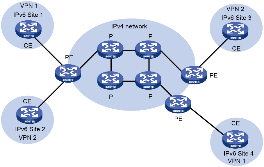
Figure 1 shows a typical IPv6 MPLS L3VPN model. The service provider backbone in the IPv6 MPLS L3VPN model is an IPv4 network. IPv6 runs inside the VPNs and between CE and PE. Therefore, PEs must support both IPv4 and IPv6. The PE-CE interfaces of a PE run IPv6, and the PE-P interface of a PE runs IPv4.
Figure 1 Network diagram for the IPv6 MPLS L3VPN model
IPv6 MPLS L3VPN packet forwarding
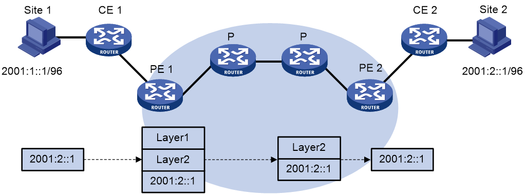
As shown in Figure 2, the IPv6 MPLS L3VPN packet forwarding procedure is as follows:
1. The PC at Site 1 sends an IPv6 packet destined for 2001:2::1, the PC at Site 2. CE 1 transmits the packet to PE 1.
2. Based on the inbound interface and destination address of the packet, PE 1 finds a matching entry from the routing table of the VPN instance, labels the packet with both a private network label (inner label) and a public network label (outer label), and forwards the packet out.
3. The MPLS backbone transmits the packet to PE 2 by outer label. The outer label is removed from the packet at the penultimate hop.
4. According to the inner label and destination address of the packet, PE 2 searches the routing table of the VPN instance to determine the outbound interface, and then forwards the packet out of the interface to CE 2.
5. CE 2 forwards the packet to the destination by IPv6 forwarding.
Figure 2 IPv6 MPLS L3VPN packet forwarding diagram
IPv6 MPLS L3VPN routing information advertisement
The routing information is advertised through the path local CE—ingress PE—egress PE—remote CE.
Routing information advertisement from the local CE to the ingress PE.
The local CE advertises standard IPv6 routing information to the ingress PE over an IPv6 static route, RIPng route, OSPFv3 route, IPv6 IS-IS route, IBGP route, or EBGP route.
Routing information advertisement from the ingress PE to the egress PE.
After receiving the standard IPv6 routes from the CE, the ingress PE performs the following operations:
1. Adds RDs and route targets to create VPN-IPv6 routes.
2. Saves the routes to the routing table of the VPN instance created for the CE.
3. Assigns VPN labels for the routes.
4. Advertises the VPN-IPv6 routes to the egress PE through MP-BGP.
The egress PE performs the following operations:
5. Compares the export target attributes of the VPN-IPv6 routes with the import target attributes that it maintains for the VPN instance.
6. Adds the routes to the routing table of the VPN instance if the export and import target attributes are the same.
The PEs use an IGP to ensure the connectivity between them.
Routing information advertisement from the egress PE to the remote peer CE.
The egress PE restores the original IPv6 routes and advertises them to the remote CE over an IPv6 static route, RIPng route, OSPFv3 route, IPv6 IS-IS route, EBGP, or IBGP route.
IPv6 MPLS L3VPN network schemes and features
IPv6 MPLS L3VPN supports the following network schemes and features:
· Basic VPN.
· Inter-AS VPN option A.
· Inter-AS VPN option B.
· Inter-AS VPN option C.
· Carrier's carrier.
· Multirole host.
· OSPFv3 VPN extension. (OSPFv3 Type 3, Type 5, and Type 7 LSAs support the DN bit. By default, OSPFv3 VPN extension uses the DN bit to avoid routing loops.)
· BGP AS number substitution and SoO.
· IPv6 MPLS L3VPN FRR.
Protocols and standards
· RFC 4659, BGP-MPLS IP Virtual Private Network (VPN) Extension for IPv6 VPN
· RFC 6565, OSPFv3 as a Provider Edge to Customer Edge (PE-CE) Routing Protocol
Restrictions and guidelines: IPv6 MPLS L3VPN configuration
The public tunnels for IPv6 MPLS L3VPN can be LSP, MPLS TE, and GRE tunnels. In the current software version, the device does not support using GRE/IPv6 tunnels as public tunnels for IPv6 MPLS L3VPN.
IPv6 MPLS L3VPN tasks at a glance
Unless otherwise indicated, configure IPv6 MPLS L3VPN on PEs.
To configure IPv6 MPLS L3VPN, perform the following tasks:
1. Configuring IPv6 MPLS L3VPN basics:
b. Configuring routing between a PE and a CE
c. Configuring routing between PEs
d. (Optional.) Configuring BGP VPNv6 route control
2. Configuring advanced IPv6 MPLS L3VPN networks
Choose the following tasks as needed:
¡ Configuring inter-AS IPv6 VPN
Perform this task when sites of a VPN are connected to different ASs of an ISP.
Multirole host allows a host or server in a site to access multiple VPNs by configuring PBR on the PE.
3. (Optional.) Configuring IPv6 MPLS L3VPN FRR
4. (Optional.) Controlling route advertisement and reception in MPLS L3VPN
¡ Configuring an OSPFv3 sham link
¡ Configuring BGP AS number substitution and SoO attribute
¡ Configuring the BGP additional path feature
¡ Enabling independent routing tables for BGP VPNv6 routes and BGP-VPN instance routes
¡ Configuring route replication
Perform this task to enable a VPN instance to communicate with the public network or other VPN instances by replicating routes from the public network or other VPN instances.
¡ Enabling prioritized withdrawal of specific routes
¡ Configuring BGP next hop recursion based on a routing policy
5. (Optional.) Enabling logging for BGP route flapping
Prerequisites for IPv6 MPLS L3VPN
Before configuring IPv6 MPLS L3VPN, perform the following tasks:
1. Configure an IGP on the PEs and P devices to ensure IP connectivity within the MPLS backbone.
2. Configure basic MPLS for the MPLS backbone.
3. Configure MPLS LDP on PEs and P devices to establish LDP LSPs.
Configuring VPN instances
Creating a VPN instance
About this task
A VPN instance is a collection of the VPN membership and routing rules of its associated site. A VPN instance might correspond to more than one VPN.
Procedure
1. Enter system view.
system-view
2. Create a VPN instance and enter VPN instance view.
ip vpn-instance vpn-instance-name
3. Configure an RD for the VPN instance.
route-distinguisher route-distinguisher
By default, no RD is configured for a VPN instance.
4. (Optional.) Configure a description for the VPN instance.
description text
By default, no description is configured for a VPN instance.
5. (Optional.) Set an ID for the VPN instance.
vpn-id vpn-id
By default, no ID is configured for a VPN instance.
6. (Optional.) Configure an SNMP context for the VPN instance.
snmp context-name context-name
By default, no SNMP context is configured.
Associating a VPN instance with a Layer 3 interface
Restrictions and guidelines
If an interface is associated with a VSI or cross-connect, the interface (including its subinterfaces) cannot associate with a VPN instance.
If a subinterface is associated with a VSI or cross-connect, the subinterface cannot associate with a VPN instance.
Procedure
1. Enter system view.
system-view
2. Enter interface view.
interface interface-type interface-number
3. Associate a VPN instance with the interface.
ip binding vpn-instance vpn-instance-name
By default, an interface is not associated with a VPN instance and belongs to the public network.
|
|
CAUTION: Associating a VPN instance with an interface or disassociating a VPN instance from an interface will clear the IP address and routing protocol settings of the interface. |
The ip binding vpn-instance command clears the IPv6 address of the interface. Therefore, reconfigure an IPv6 address for the interface after configuring this command.
Configuring route related attributes for a VPN instance
Restrictions and guidelines
Configurations made in VPN instance view apply to both IPv4 VPN and IPv6 VPN.
IPv6 VPN prefers the configurations in VPN instance IPv6 address family view over the configurations in VPN instance view.
Prerequisites
Before you perform this task, create the routing policies to be used by this task. For information about routing policies, see Layer 3—IP Routing Configuration Guide.
Procedure
1. Enter system view.
system-view
2. Enter VPN instance view or VPN instance IPv6 address family view.
¡ Enter VPN instance view.
ip vpn-instance vpn-instance-name
¡ Execute the following commands in sequence to enter VPN instance IPv6 address family view:
ip vpn-instance vpn-instance-name
address-family ipv6
3. Configure route targets.
vpn-target vpn-target&<1-8> [ both | export-extcommunity | import-extcommunity ]
By default, no route targets are configured.
4. Set the maximum number of active routes.
routing-table limit number { warn-threshold | simply-alert }
By default, the number of active routes in a VPN instance is not limited.
Setting the maximum number of active routes for a VPN instance can prevent the PE from storing too many routes.
5. Apply an import routing policy.
import route-policy route-policy
By default, all routes matching the import target attribute are accepted.
6. Apply an export routing policy.
export route-policy route-policy
By default, routes to be advertised are not filtered.
7. Apply a tunnel policy to the VPN instance.
tnl-policy tunnel-policy-name
By default, only one tunnel is selected (no load balancing) in this order: LSP tunnel, GRE tunnel, and CRLSP tunnel.
If the specified tunnel policy does not exist, the default tunnel policy is used.
For information about tunnel policies, see "Configuring tunnel policies."
Configuring routing between a PE and a CE
Configuring IPv6 static routing between a PE and a CE
About this task
Perform this configuration on the PE. On the CE, configure a common IPv6 static route.
For more information about IPv6 static routing, see Layer 3—IP Routing Configuration Guide.
Procedure
1. Enter system view.
system-view
2. Configure an IPv6 static route for a VPN instance.
ipv6 route-static vpn-instance s-vpn-instance-name ipv6-address prefix-length { interface-type interface-number [ next-hop-address ] | nexthop-address [ public ] | vpn-instance d-vpn-instance-name nexthop-address } [ permanent ] [ preference preference ] [ tag tag-value ] [ description text ]
Configuring RIPng between a PE and a CE
About this task
Perform this configuration on the PE. On the CE, configure a common RIPng process.
For more information about RIPng, see Layer 3—IP Routing Configuration Guide.
Procedure
1. Enter system view.
system-view
2. Create a RIPng process for a VPN instance and enter RIPng view.
ripng [ process-id ] vpn-instance vpn-instance-name
A RIPng process can belong to only one VPN instance.
3. Redistribute BGP routes.
import-route bgp4+ [ as-number ] [ allow-ibgp ] [ cost cost-value | route-policy route-policy-name ] *
By default, RIPng does not redistribute routes from other routing protocols.
4. Return to system view.
quit
5. Enter interface view.
interface interface-type interface-number
6. Enable RIPng on the interface.
ripng process-id enable
By default, RIPng is disabled on an interface.
Configuring OSPFv3 between a PE and a CE
About this task
Perform this configuration on the PE. On the CE, configure a common OSPFv3 process.
For more information about OSPFv3, see Layer 3—IP Routing Configuration Guide.
Procedure
1. Enter system view.
system-view
2. Create an OSPFv3 process for a VPN instance and enter OSPFv3 view.
ospfv3 [ process-id | vpn-instance vpn-instance-name ] *
An OSPFv3 process can belong to only one VPN instance.
Deleting a VPN instance also deletes all related OSPFv3 processes.
3. Set the router ID.
router-id router-id
4. Redistribute BGP routes.
import-route bgp4+ [ as-number ] [ allow-ibgp ] [ cost cost-value | nssa-only | route-policy route-policy-name | tag tag | type type ] *
By default, OSPFv3 does not redistribute routes from other routing protocols.
If the vpn-instance-capability simple command is not configured for the OSPFv3 process, the allow-ibgp keyword is optional to redistribute VPNv6 routes learned from MP-IBGP peers. In any other cases, if you do not specify the allow-ibgp keyword, the OSPFv3 process does not redistribute VPNv6 routes learned from MP-IBGP peers.
5. (Optional.) Configure OSPFv3 route attributes:
a. Set an OSPFv3 domain ID.
domain-id { domain-id [ secondary ] | null }
The default domain ID is 0.
|
Description |
Restrictions and guidelines |
|
When you redistribute OSPFv3 routes into BGP, BGP adds the primary domain ID to the redistributed BGP routes as a BGP extended community attribute. |
You can configure the same domain ID for different OSPFv3 processes. You must configure the same domain ID for all OSPFv3 processes of the same VPN to ensure correct route advertisement. |
b. Configure the type code of an OSPFv3 extended community attribute.
ext-community-type { domain-id type-code1 | route-type type-code2 | router-id type-code3 }
By default, the type codes for domain ID, route type, and router ID are 0x0005, 0x0306, 0x0107, respectively.
c. Configure an external route tag for redistributed VPN routes.
route-tag tag-value
By default, if BGP runs within an MPLS backbone, and the BGP AS number is not greater than 65535, the first two octets of the external route tag are 0xD000. The last two octets are the local BGP AS number. If the AS number is greater than 65535, the external route tag is 0.
d. Disable setting the DN bit in OSPFv3 LSAs.
disable-dn-bit-set
By default, when a PE redistributes BGP routes into OSPFv3 and creates OSPFv3 LSAs, it sets the DN bit for the LSAs.
This command might cause routing loops. Use it with caution.
e. Ignore the DN bit in OSPFv3 LSAs.
disable-dn-bit-check
By default, the PE checks the DN bit in OSPFv3 LSAs.
This command might cause routing loops. Use it with caution.
f. Enable the external route check feature for OSPFv3 LSAs.
route-tag-check enable
By default, the PE does not check the external route tag but checks the DN bit in OSPFv3 LSAs to avoid routing loops.
This command is only for backward compatibility with the old protocol (RFC 4577).
g. Return to system view.
quit
6. Enter interface view.
interface interface-type interface-number
7. Enable OSPFv3 on the interface.
ospfv3 process-id area area-id [ instance instance-id ]
By default, OSPFv3 is disabled on an interface.
For the command to be executed successfully, make sure the VPN instance to which the OSPFv3 process belongs is the VPN instance bound to the interface.
Configuring IPv6 IS-IS between a PE and a CE
About this task
Perform this configuration on the PE. On the CE, configure a common IPv6 IS-IS process.
For more information about IPv6 IS-IS, see Layer 3—IP Routing Configuration Guide.
Procedure
1. Enter system view.
system-view
2. Create an IPv6 IS-IS process for a VPN instance and enter IS-IS view.
isis [ process-id ] vpn-instance vpn-instance-name
An IPv6 IS-IS process can belong to only one VPN instance.
3. Configure a network entity title for the IS-IS process.
network-entity net
By default, no NET is configured.
4. Create the IS-IS IPv6 unicast address family and enter its view.
address-family ipv6 [ unicast ]
5. Redistribute BGP routes.
import-route bgp4+ [ as-number ] [ allow-ibgp ] [ cost cost-value ] | [ level-1 | level-1-2 | level-2 ] | route-policy route-policy-name | tag tag ] *
By default, IPv6 IS-IS does not redistribute routes from other routing protocols.
6. Return to system view.
quit
quit
7. Enter interface view.
interface interface-type interface-number
8. Enable IPv6 for the IS-IS process on the interface.
isis ipv6 enable [ process-id ]
By default, IPv6 is disabled for the IS-IS process on the interface.
Configuring EBGP between a PE and a CE
Configuring the PE
1. Enter system view.
system-view
2. Enable a BGP instance and enter BGP instance view.
bgp as-number [ instance instance-name ]
By default, BGP is not enabled.
3. Enter BGP-VPN instance view.
ip vpn-instance vpn-instance-name
4. Configure the CE as the VPN EBGP peer.
peer { group-name | ipv6-address [ prefix-length ] } as-number as-number
5. Create the BGP-VPN IPv6 unicast address family and enter its view.
address-family ipv6 [ unicast ]
Configuration commands in BGP-VPN IPv6 unicast address family view are the same as those in BGP IPv6 unicast address family view. For more information, see basic BGP configuration in Layer 3—IP Routing Configuration Guide.
6. Enable IPv6 unicast route exchange with the specified peer.
peer { group-name | ip-address [ prefix-length ] } enable
By default, BGP does not exchange IPv6 unicast routes with a peer.
7. Redistribute the routes of the local CE.
import-route protocol [ { process-id | all-processes } [ allow-direct | med med-value | route-policy route-policy-name ] * ]
A PE must redistribute the routes of the local CE into its VPN routing table so that it can advertise them to the peer PE.
8. (Optional.) Allow the local AS number to appear in the AS_PATH attribute of a received route, and set the maximum number of repetitions.
peer { group-name | ipv6-address [ prefix-length ] } allow-as-loop [ number ]
By default, BGP discards incoming route updates that contain the local AS number.
Execute this command in a hub-spoke network where EBGP is running between a PE and a CE to enable the PE to receive the route updates from the CE.
Configuring the CE
1. Enter system view.
system-view
2. Enter BGP instance view.
bgp as-number [ instance instance-name ]
3. Configure the PE as an EBGP peer.
peer { group-name | ipv6-address [ prefix-length ] } as-number as-number
4. Create the BGP IPv6 unicast address family and enter its view.
address-family ipv6 [ unicast ]
5. Enable IPv6 unicast route exchange with the specified peer.
peer { group-name | ip-address [ prefix-length ] } enable
By default, BGP does not exchange IPv6 unicast routes with a peer.
6. Configure route redistribution.
import-route protocol [ { process-id | all-processes } [ allow-direct | med med-value | route-policy route-policy-name ] * ]
A CE must advertise its VPN routes to the connected PE so that the PE can advertise them to the peer CE.
Configuring IBGP between a PE and a CE
Restrictions and guidelines
Use IBGP between PE and CE only in a basic IPv6 MPLS L3VPN network. In networks such as inter-AS VPN and carrier's carrier, you cannot configure IBGP between PE and CE.
Configuring the PE
1. Enter system view.
system-view
2. Enter BGP instance view.
bgp as-number [ instance instance-name ]
3. Enter BGP-VPN instance view.
ip vpn-instance vpn-instance-name
Configuration commands in BGP-VPN instance view are the same as those in BGP instance view. For more information, see basic BGP configuration in Layer 3—IP Routing Configuration Guide.
4. Configure the CE as the VPN IBGP peer.
peer { group-name | ipv6-address [ prefix-length ] } as-number as-number
5. Create the BGP-VPN IPv6 unicast address family and enter its view.
address-family ipv6 [ unicast ]
6. Enable IPv6 unicast route exchange with the specified peer.
peer { group-name | ipv6-address [ prefix-length ] } enable
By default, BGP does not exchange IPv6 unicast routes with a peer.
7. Configure the CE as a client of the RR to enable the PE to advertise routes learned from the IBGP peer CE to other IBGP peers.
peer { group-name | ipv6-address [ prefix-length ] } reflect-client
By default, no RR or RR client is configured.
Configuring an RR does not change the next hop of a route. To change the next hop of a route, configure an inbound policy on the receiving side.
8. (Optional.) Enable route reflection between clients.
reflect between-clients
By default, route reflection between clients is enabled.
9. (Optional.) Configure the cluster ID for the RR.
reflector cluster-id { cluster-id | ip-address }
By default, the RR uses its own router ID as the cluster ID.
If multiple RRs exist in a cluster, use this command to configure the same cluster ID for all RRs in the cluster to avoid routing loops.
Configuring the CE
1. Enter system view.
system-view
2. Enter BGP instance view.
bgp as-number [ instance instance-name ]
3. Configure the PE as an IBGP peer.
peer { group-name | ipv6-address [ prefix-length ] } as-number as-number
4. Create the BGP IPv6 unicast family and enter its view.
address-family ipv6 [ unicast ]
5. Enable IPv6 unicast route exchange with the specified peer.
peer { group-name | ipv6-address [ prefix-length ] } enable
By default, BGP does not exchange IPv6 unicast routes with a peer.
6. Configure route redistribution.
import-route protocol [ { process-id | all-processes } [ allow-direct | med med-value | route-policy route-policy-name ] * ]
A CE must redistribute its routes to the PE so the PE can advertise them to the peer CE.
Configuring routing between PEs
1. Enter system view.
system-view
2. Enter BGP instance view.
bgp as-number [ instance instance-name ]
3. Configure the remote PE as the peer.
peer { group-name | ipv4-address [ mask-length ] } as-number as-number
4. Specify the source interface for TCP connections.
peer { group-name | ipv4-address [ mask-length ] } connect-interface interface-type interface-number
By default, BGP uses the outbound interface of the best route to the BGP peer as the source interface.
5. Create the BGP VPNv6 address family and enter its view.
address-family vpnv6
6. Enable BGP VPNv6 route exchange with the specified peer.
peer { group-name | ipv4-address [ mask-length ] } enable
By default, BGP does not exchange BGP VPNv6 routes with any peer.
Configuring BGP VPNv6 route control
About BGP VPNv6 route control
BGP VPNv6 route control is configured similarly with BGP route control, except that it is configured in BGP VPNv6 address family view. For more information about BGP route control, see basic BGP configuration and advanced BGP configuration in Layer 3—IP Routing Configuration Guide.
Specifying a preferred value for BGP VPNv6 routes
1. Enter system view.
system-view
2. Enter BGP instance view.
bgp as-number [ instance instance-name ]
3. Enter BGP VPNv6 address family view.
address-family vpnv6
4. Specify a preferred value for routes received from a peer or peer group.
peer { group-name | ipv4-address [ mask-length ] } preferred-value value
The default preferred value is 0.
Setting the maximum number of received routes
1. Enter system view.
system-view
2. Enter BGP instance view.
bgp as-number [ instance instance-name ]
3. Enter BGP VPNv6 address family view.
address-family vpnv6
4. Set the maximum number of routes BGP can receive from a peer or peer group.
peer { group-name | ipv4-address [ mask-length ] } route-limit prefix-number [ { alert-only | discard | reconnect reconnect-time } | percentage-value ] *
By default, the number of routes that BGP can receive from a peer or peer group is not limited.
Configuring BGP VPNv6 route reflection
About this task
To ensure the connectivity of IBGP peers, you must establish full-mesh IBGP connections, which costs massive network and CPU resources.
To reduce IBGP connections in the network, you can configure a router as a route reflector (RR) and configure other routers as its clients. You only need to establish IBGP connections between the RR and its clients to enable the RR to forward routes to the clients.
Procedure
1. Enter system view.
system-view
2. Enter BGP instance view.
bgp as-number [ instance instance-name ]
3. Enter BGP VPNv6 address family view.
address-family vpnv6
4. Configure the local PE as the RR and specify the peer as the client.
peer { group-name | ipv4-address [ mask-length ] } reflect-client
By default, no RR or client is configured.
5. (Optional.) Enable route reflection between clients.
reflect between-clients
By default, route reflection between clients is enabled.
6. (Optional.) Configure a cluster ID for the RR.
reflector cluster-id { cluster-id | ip-address }
By default, an RR uses its own router ID as the cluster ID.
If multiple RRs exist in a cluster, use this command to configure the same cluster ID for all RRs in the cluster to avoid routing loops.
7. (Optional.) Configure a filtering policy for reflected routes.
rr-filter { ext-comm-list-number | ext-comm-list-name }
By default, an RR does not filter reflected routes.
Only IBGP routes whose extended community attribute matches the specified community list are reflected.
By configuring different filtering policies on RRs, you can implement load balancing among the RRs.
8. (Optional.) Allow the RR to change the attributes of routes to be reflected.
reflect change-path-attribute
By default, RR cannot change the attributes of routes to be reflected.
9. (Optional.) Specify a peer or peer group as a client of the nearby cluster.
peer { group-name | ipv4-address [ mask-length ] } reflect-nearby-group
By default, the nearby cluster does not have any clients.
The RR does not change the next hop of routes reflected to clients in the nearby cluster.
Configuring BGP VPNv6 route attributes
1. Enter system view.
system-view
2. Enter BGP instance view.
bgp as-number [ instance instance-name ]
3. Enter BGP VPNv6 address family view.
address-family vpnv6
4. Configure the NEXT_HOP attribute.
¡ Set the device as the next hop for routes sent to a peer or peer group.
peer { group-name | ipv4-address [ mask-length ] } next-hop-local
¡ Configure the device to not change the next hop of routes advertised to a peer or peer group.
peer { group-name | ipv4-address [ mask-length ] } next-hop-invariable
By default, the device uses its address as the next hop of routes advertised to peers.
The peer next-hop-local command and the peer next-hop-invariable command are mutually exclusive with each other.
On an RR in an inter-AS option C scenario, you must configure this command to not change the next hop of VPNv6 routes advertised to BGP peers and RR clients.
5. Configure the AS_PATH attribute.
¡ Allow the local AS number to appear in the AS_PATH attribute of routes received from a peer or peer group and set the maximum number of repetitions.
peer { group-name | ipv4-address [ mask-length ] } allow-as-loop [ number ]
By default, BGP discards route updates that contain the local AS number.
¡ Remove private AS numbers in BGP updates sent to an EBGP peer or peer group.
peer { group-name | ipv4-address [ mask-length ] } public-as-only [ { force | limited } [ replace ] [ include-peer-as ] ]
By default, BGP updates sent to an EBGP peer or peer group can carry both public and private AS numbers.
6. Advertise the COMMUNITY attribute to a peer or peer group.
peer { group-name | ipv4-address [ mask-length ] } advertise-community
By default, BGP does not advertise the COMMUNITY attribute to any peers or peer groups.
7. Configure the link bandwidth attribute.
¡ Configure a link bandwidth attribute for a peer or peer group.
peer { group-name | ipv4-address [ mask-length ] } bandwidth [ bandwidth-value ]
By default, no link bandwidth attribute is configured for a peer or peer group.
¡ (Optional.) Configure the device to advertise link bandwidth attributes to EBGP peers.
peer { group-name | ipv4-address [ mask-length ] } advertise ebgp bandwidth
By default, the device does not advertise link bandwidth attributes to EBGP peers.
¡ (Optional.) Convert the link bandwidth attributes to optional transitive attributes in the BGP routes to be advertised to a peer or peer group.
peer { group-name | ipv4-address [ mask-length ] } advertise bandwidth transitive
By default, the link bandwidth attributes in BGP routes are optional non-transitive attributes.
8. Configure the SoO attribute for a peer for peer group.
peer { group-name | ipv4-address [ mask-length ] } soo site-of-origin
By default, the SoO attribute is not configured.
9. Minimize the priority of BGP routes advertised to peers. Choose one of the following options:
¡ Minimize the priority of BGP routes advertised to peers with a down-to-up state change.
advertise lowest-priority on-peer-up duration seconds
¡ Minimize the priority of BGP routes advertised to peers after a device reboot.
advertise lowest-priority on-startup duration seconds
By default, the device does not change the priority of BGP routes advertised to peers.
The device minimizes the priority of BGP routes advertised to peers by setting the routes' local preference value to the minimum (0) and the MED value to the maximum (4294967295). To restore the original priority of the BGP routes before the wait time expires, execute the reset bgp advertise lowest-priority command in user view.
Configuring BGP VPNv6 route filtering
1. Enter system view.
system-view
2. Enter BGP instance view.
bgp as-number [ instance instance-name ]
3. Enter BGP VPNv6 address family view.
address-family vpnv6
4. Filter advertised routes.
filter-policy { ipv6-acl-number | prefix-list ipv6-prefix-name } export [ direct | { isisv6 | ospfv3 | ripng } process-id | static ]
By default, BGP does not filter advertised routes.
5. Filter received routes.
filter-policy { ipv6-acl-number | prefix-list ipv6-prefix-name } import
By default, BGP does not filter received routes.
6. Configure AS_PATH list-based route filtering for a peer or peer group.
peer { group-name | ipv4-address [ mask-length ] } as-path-acl as-path-acl-number { export | import }
By default, AS_PATH list-based route filtering is not configured.
7. Configure ACL-based route filtering for a peer or peer group.
peer { group-name | ipv4-address [ mask-length ] } filter-policy ipv6-acl-number { export | import }
By default, ACL-based route filtering is not configured.
8. Configure IPv6 prefix list-based route filtering for a peer or peer group.
peer { group-name | ipv4-address [ mask-length ] } prefix-list ipv6-prefix-name { export | import }
By default, IPv6 prefix list-based route filtering is not configured.
9. Apply a routing policy to routes advertised to or received from a peer or peer group.
peer { group-name | ipv4-address [ mask-length ] } route-policy route-policy-name { export | import }
By default, no routing policy is applied.
10. Enable the first AS number check for EBGP route advertisement to EBGP peers.
peer-as-check enable
By default, BGP does not check the first AS number of a received route and advertises the route to other peers.
After you execute this command, BGP checks the first AS number of a received route. If the AS number of an EBGP peer is the first AS number of the EBGP route to be advertised, BGP will not advertise the route to that EBGP peer.
Configuring BGP VPNv6 routes to use private network next hops
About this task
By default, the device does not change the next hop attribute of a received BGP VPNv6 route. The next hop address of a BGP VPNv6 route is a public address. This feature changes the next hop of a BGP VPNv6 route received from a peer or peer group to an IP address in the VPN instance. The outgoing label of the VPNv6 route is also changed to an invalid value. For example, the device received a VPNv6 route and its next hop address is 10.1.1.1, which is a public address by default. After this feature is configured, the next hop address changes to private address 10.1.1.1.
Restrictions and guidelines
After you configure this feature, the following applies:
· The device re-establishes the BGP sessions to the specified peer or to all peers in the specified peer group.
· The device receives a BGP VPNv6 route only when its RD is the same as a local RD.
· When advertising a BGP VPNv6 route received from the specified peer or peer group, the device does not change the route target attribute of the route.
· If you delete a VPN instance or its RD, BGP VPNv6 routes received from the specified peer or peer group and in the VPN instance will be deleted.
Procedure
1. Enter system view.
system-view
2. Enter BGP instance view.
bgp as-number [ instance instance-name ]
3. Enter BGP VPNv6 address family view.
address-family vpnv6
4. Change the next hop of a BGP VPNv6 route received from a peer or peer group to a VPN instance address.
peer { group-name | ipv4-address [ mask-length ] } next-hop-vpn
By default, the device does not change the next hop attribute of a received BGP VPNv6 route, and the next hop belongs to the public network.
Configuring BGP VPNv6 optimal route selection delay
1. Enter system view.
system-view
2. Enter BGP instance view.
bgp as-number [ instance instance-name ]
3. Enter BGP VPNv6 address family view.
address-family vpnv6
4. Set the BGP VPNv6 optimal route selection delay timer. Choose one or more of the following tasks:
¡ Configure optimal route selection delay for all BGP routes in the address family.
route-select delay delay-value
¡ Configure optimal route selection delay only for BGP routes from a peer within the specified time after the peer state changes from down to up.
route-select suppress on-peer-up milliseconds
By default, optimal route selection is not delayed.
Preferring routes learned from the specified peer or peer group during optimal route selection
About this task
The VPNv6 address family supports both IPv4 and IPv6 peers, so the device might learn routes with the same prefix from the IPv4 and IPv6 peers. You can perform this task to control the route priorities.
When an IPv6 MPLS L3VPN supports both IPv4 and IPv6, the VPNv6 address family might learn routes with the same prefix from the IPv4 and IPv6 peers. In this scenario, the route learned from the IPv4 peer might be selected as the optimal route, and the route learned from the IPv6 peer will not be advertised. You can configure this feature on the IPv6 peers in the VPNv6 address family to ensure that routes learned from the IPv6 peers are preferred.
Procedure
1. Enter system view.
system-view
2. Enter BGP instance view.
bgp as-number [ instance instance-name ]
3. Enter BGP VPNv6 address family view.
address-family vpnv6
4. Prefer routes learned from the specified peer or peer group during optimal route selection.
peer { group-name | ipv4-address [ mask-length ] } high-priority
By default, routes learned from a peer or peer group do not take precedence over routes learned from other peers or peer groups.
Advertising BGP RPKI validation state to a peer or peer group
Restrictions and guidelines
BGP advertises the BGP RPKI validation state to a peer or peer group through the extended community attribute. For more information about BGP RPKI, see BGP configuration in Layer 3—IP Routing Configuration Guide.
Procedure
1. Enter system view.
system-view
2. Enter BGP instance view.
bgp as-number [ instance instance-name ]
3. Enter BGP VPNv6 address family view.
address-family vpnv6
4. Advertise the BGP RPKI validation state to the specified peer or peer group.
peer { group-name | ipv4-address [ mask-length ] } advertise origin-as-validation
By default, BGP does not advertise the BGP RPKI validation state.
Configuring inter-AS IPv6 VPN
Configuring inter-AS IPv6 VPN option A
Inter-AS IPv6 VPN option A applies to scenarios where the number of VPNs and that of VPN routes on the PEs are relatively small.
To configure inter-AS IPv6 option A, perform the following tasks:
· Configure basic IPv6 MPLS L3VPN on each AS.
· Configure VPN instances on both PEs and ASBRs. The VPN instances on PEs allow CEs to access the network, and those on ASBRs are for access of the peer ASBRs.
In the inter-AS IPv6 VPN option A solution, for the same IPv6 VPN, the route targets configured on the PEs must match those configured on the ASBRs in the same AS. This makes sure VPN routes sent by the PEs (or ASBRs) can be received by the ASBRs (or PEs). Route targets configured on the PEs in different ASs do not have such requirements.
Configuring inter-AS IPv6 VPN option B
Restrictions and guidelines
An ASBR always uses its address as the next hop of VPNv6 routes advertised to an MP-IBGP peer regardless of the configuration of the peer next-hop-local command.
Configuring a PE
Configure basic IPv6 MPLS L3VPN, and specify the ASBR in the same AS as an MP-IBGP peer. The route targets for the VPN instances on the PEs in different ASs must match for the same IPv6 VPN.
Configuring an ASBR
1. Enter system view.
system-view
2. Enable MPLS and LDP on the interface connected to an internal router of the AS:
a. Configure an LSR ID for the local LSR.
mpls lsr-id lsr-id
By default, no LSR ID is configured.
b. Enable LDP on the local LSR and enter LDP view.
mpls ldp
By default, LDP is disabled.
c. Return to system view.
quit
d. Enter interface view of the interface connected to an internal router of the AS.
interface interface-type interface-number
e. Enable MPLS on the interface.
mpls enable
By default, MPLS is disabled on the interface.
f. Enable MPLS LDP on the interface.
mpls ldp enable
By default, MPLS LDP is disabled on the interface.
g. Return to system view.
quit
3. Enable MPLS on the interface connected to the remote ASBR:
a. Enter interface view of the interface connected to the remote ASBR.
interface interface-type interface-number
b. Enable MPLS on the interface.
mpls enable
By default, MPLS is disabled on the interface.
c. Return to system view.
quit
4. Enter BGP instance view.
bgp as-number [ instance instance-name ]
5. Configure PEs in the same AS as IBGP peers and ASBRs in different ASs as EBGP peers.
peer { group-name | ipv4-address [ mask-length ] } as-number as-number
6. Enter BGP VPNv6 address family view.
address-family vpnv6
7. Enable BGP to exchange VPNv6 routes with the PE in the same AS and the ASBR in another AS.
peer { group-name | ipv4-address [ mask-length ] } enable
By default, BGP cannot exchange VPNv6 routing information with a peer.
8. Disable route target filtering of received VPNv6 routes.
undo policy vpn-target
By default, route target filtering is enabled for received VPNv6 routes.
Configuring inter-AS IPv6 VPN option C
Prerequisites
Before you configure inter-AS option C, perform the following tasks:
· Configure BGP to advertise routes destined for a PE on PEs or ASBRs. For more information, see basic BGP configuration in Layer 3—IP Routing Configuration Guide.
· Configure a VPN instance on the PE.
· Configure routing between the PE and CE.
Configuring a PE
1. Enter system view.
system-view
2. Enter BGP instance view.
bgp as-number [ instance instance-name ]
3. Configure the ASBR in the same AS as an IBGP peer and Configure the PE in another AS as an EBGP peer
peer { group-name | ipv4-address [ mask-length ] } as-number as-number
4. Enter BGP IPv4 unicast address family view.
address-family ipv4 [ unicast ]
5. Enable BGP to exchange BGP IPv4 unicast routes with the ASBR in the same AS.
peer { group-name | ipv4-address [ mask-length ] } enable
By default, the PE does not exchange BGP IPv4 unicast routes with any peer.
6. Enable BGP to exchange labeled routes with the ASBR in the same AS.
peer { group-name | ipv4-address [ mask-length ] } label-route-capability
By default, the PE does not advertise labeled routes to any IPv4 peer or peer group.
7. Return to BGP instance view.
quit
8. Enter BGP VPNv6 address family view.
address-family vpnv6
9. Enable BGP to exchange BGP VPNv6 routing information with the EBGP peer.
peer ipv4-address [ mask-length ] enable
By default, the PE does not exchange labeled routes with an IPv4 peer.
10. (Optional.) Configure the PE to not change the next hop of routes advertised to the peer.
peer { group-name | ipv4-address [ mask-length ] } next-hop-invariable
By default, the device uses its address as the next hop of routes advertised to peers.
Configure this command on the RR so the RR does not change the next hop of advertised VPNv6 routes.
Configuring an ASBR-PE
1. Enter system view.
system-view
2. Configure a routing policy:
a. Create a routing policy, and enter routing policy view.
route-policy route-policy-name { deny | permit } node node-number
b. Match IPv4 routes carrying labels.
if-match mpls-label
By default, no MPLS label match criterion is configured.
You can configure if-match clauses in the routing policy to filter routes. Routes surviving the filtering are assigned labels, and all others are advertised as common IPv4 routes.
c. Set labels for IPv4 routes.
apply mpls-label
By default, no MPLS label is set for IPv4 routes.
d. Return to system view.
quit
3. Enable MPLS and LDP on the interface connected to an internal router of the AS:
a. Configure an LSR ID for the local LSR.
mpls lsr-id lsr-id
By default, no LSR ID is configured.
By default, no LSR
b. Enable LDP for the local LSR and enter LDP view.
mpls ldp
By default, LDP is disabled.
c. Return to system view.
quit
d. Enter interface view of the interface connected to an internal router of the AS.
interface interface-type interface-number
e. Enable MPLS on the interface.
mpls enable
By default, MPLS is disabled on the interface.
f. Enable MPLS LDP on the interface.
mpls ldp enable
By default, MPLS LDP is disabled on the interface.
g. Return to system view.
quit
4. Enable MPLS on the interface connected to the remote ASBR:
a. Enter interface view of the interface connected to the remote ASBR.
interface interface-type interface-number
b. Enable MPLS on the interface.
mpls enable
By default, MPLS is disabled on the interface.
c. Return to system view.
quit
5. Enter BGP instance view.
bgp as-number [ instance instance-name ]
6. Configure the PE in the same AS as an IBGP peer and the ASBR in another AS as an EBGP peer.
peer { group-name | ipv4-address [ mask-length ] } as-number as-number
7. Create the BGP IPv4 unicast address family and enter its view.
address-family ipv4 [ unicast ]
8. Enable IPv4 unicast route exchange with the PE in the same AS and the ASBR in another AS.
peer { group-name | ipv4-address [ mask-length ] } enable
By default, BGP cannot exchange IPv4 unicast routes with any peer.
9. Enable labeled IPv4 route exchange with the PE in the same AS and the ASBR in another AS.
peer { group-name | ipv4-address [ mask-length ] } label-route-capability
By default, BGP cannot exchange labeled IPv4 routes with any peer.
10. Configure the ASBR to set itself as the next hop of routes advertised to the PE in the local AS.
peer { group-name | ipv4-address [ mask-length ] } next-hop-local
By default, BGP does not use its address as the next hop of routes.
11. Apply a routing policy to routes incoming from or outgoing to a peer or peer group.
peer { group-name | ipv4-address [ mask-length ] } route-policy route-policy-name { export | import }
By default, no routing policy is applied.
Configuring multirole host
About configuring multirole host
To configure the multirole host feature for IPv6 networks, perform the following tasks on the PE connected to the CE in the site where the multirole host resides:
· Configure and apply IPv6 PBR.
· Configure IPv6 static routes.
Configuring and applying IPv6 PBR
1. Enter system view.
system-view
2. Create an IPv6 policy node and enter IPv6 policy node view.
ipv6 policy-based-route policy-name { deny | permit } node node-number
3. Configure match criteria for the node.
See Layer 3—IP Routing Configuration Guide.
By default, no match criterion is configured. All packets match the criteria for the node.
This step matches packets from the multirole host.
4. Specify the VPN instances for forwarding the matching packets.
apply access-vpn vpn-instance vpn-instance-name&<1-n>
By default, no VPN instance is specified.
You must specify multiple VPN instances for the node. The first one is the VPN instance to which the multirole host belongs, and others are the VPN instances to be accessed. A matching packet is forwarded according to the routing table of the first VPN instance that has a matching route for that packet.
5. Return to system view.
quit
6. Enter the view of the interface connected to the CE.
interface interface-type interface-number
7. Apply the policy to the interface.
ipv6 policy-based-route policy-name
By default, no policy is applied to the interface.
Configuring an IPv6 static route
1. Enter system view.
system-view
2. Configure an IPv6 static route for a VPN instance to reach the multirole host.
ipv6 route-static vpn-instance s-vpn-instance-name ipv6-address prefix-length vpn-instance d-vpn-instance-name nexthop-address [ permanent ] [ preference preference ] [ tag tag-value ] [ description text ]
The d-vpn-instance-name argument represents the VPN instance to which the multirole host belongs. The next-hop-address argument represents the IPv6 address of the CE in the site where the multirole host resides.
Configuring IPv6 MPLS L3VPN FRR
About IPv6 MPLS L3VPN FRR
You can use the following methods to configure IPv6 MPLS L3VPN FRR:
· Method 1—Execute the fast-reroute route-policy command in BGP-VPN IPv6 unicast address family view to use a routing policy. In the routing policy, specify a backup next hop by using the apply fast-reroute backup-nexthop command. The backup next hop calculated by the device must be the same as the specified backup next hop. Otherwise, the device does not generate a backup next hop for the primary route. You can also configure if-match clauses in the routing policy to identify the routes protected by FRR.
· Method 2—Execute the pic command in BGP-VPN IPv6 unicast address family view or BGP VPNv6 address family view. The device calculates a backup next hop for each BGP route in the VPN instance if there are two or more unequal-cost routes to reach the destination.
If both methods are configured, Method 1 takes precedence over Method 2.
Restrictions and guidelines
Executing the pic command in BGP-VPN IPv6 unicast address family view or BGP VPNv6 address family view might cause routing loops. Use it with caution.
Configuring FRR by using a routing policy
1. Enter system view.
system-view
2. Configure BFD.
¡ Enable MPLS BFD.
mpls bfd enable
By default, MPLS BFD is disabled.
This command is required for VPNv6 route backup for a VPNv6 route and IPv6 route backup for a VPNv6 route.
For more information about this command, see MPLS OAM commands in MPLS Command Reference.
¡ Configure the source IP address for BFD echo packets.
bfd echo-source-ip ip-address
By default, the source IP address for BFD echo packets is not configured.
This command is required when echo-mode BFD is used to detect primary route connectivity in VPNv6 route backup for an IPv6 route. For more information about this command, see BFD commands in High Availability Command Reference.
3. Use BFD to test the connectivity of an LSP or MPLS TE tunnel.
¡ Configure BFD to test the connectivity of the LSP for the specified FEC.
mpls bfd dest-addr mask-length [ nexthop nexthop-address [ discriminator local local-id remote remote-id ] ] [ template template-name ]
¡ Configure BFD to test the tunnel connectivity for an MPLS TE tunnel interface.
interface tunnel number mode mpls-te
mpls bfd [ discriminator local local-id remote remote-id ] [ template template-name ]
quit
By default, BFD is not configured to test the LSP or MPLS TE tunnel connectivity.
This step is required for VPNv6 route backup for a VPNv6 route and IPv6 route backup for a VPNv6 route.
For more information about the commands in this step, see MPLS OAM commands in MPLS Command Reference.
4. Configure a routing policy:
a. Create a routing policy and enter routing policy view.
route-policy route-policy-name permit node node-number
b. Set the backup next hop for FRR.
apply ipv6 fast-reroute backup-nexthop ipv6-address
By default, no backup next hop address is set for FRR.
c. Return to system view.
quit
For more information about the commands, see routing policy commands in Layer 3—IP Routing Command Reference.
5. Enter BGP instance view.
bgp as-number [ instance instance-name ]
6. (Optional.) Use echo-mode BFD to detect the connectivity to the next hop of the primary route.
primary-path-detect bfd echo
By default, ARP is used to detect the connectivity to the next hop.
Use this command if necessary in VPNv6 route backup an IPv6 route.
For more information about this command, see advanced BGP commands in Layer 3—IP Routing Command Reference.
7. Enter BGP-VPN instance view.
ip vpn-instance vpn-instance-name
8. Enter BGP-VPN IPv6 unicast address family view.
address-family ipv6 [ unicast ]
9. Apply a routing policy to FRR.
fast-reroute route-policy route-policy-name
By default, no routing policy is applied to FRR.
The apply ipv6 fast-reroute backup-nexthop command can take effect in the routing policy that is being used. Other apply commands do not take effect.
For more information about the command, see advanced BGP commands in Layer 3—IP Routing Command Reference.
Enabling IPv6 MPLS L3VPN FRR for an address family
1. Enter system view.
system-view
2. Configure BFD.
¡ Enable MPLS BFD.
mpls bfd enable
By default, MPLS BFD is disabled.
This command is required for VPNv6 route backup for a VPNv6 route and IPv6 route backup for a VPNv6 route. For more information about this command, see MPLS OAM commands in MPLS Command Reference.
¡ Configure the source IP address for BFD echo packets.
bfd echo-source-ip ip-address
By default, the source IP address for BFD echo packets is not configured.
This command is required when echo-mode BFD is used to detect primary route connectivity in VPNv6 route backup for an IPv6 route. For more information about this command, see BFD commands in High Availability Command Reference.
3. Use BFD to test the connectivity of an LSP or MPLS TE tunnel.
¡ Use BFD to test the connectivity of the LSP for the specified FEC.
mpls bfd dest-addr mask-length [ nexthop nexthop-address [ discriminator local local-id remote remote-id ] ] [ template template-name ]
¡ Use BFD to test the tunnel connectivity for an MPLS TE tunnel interface.
interface tunnel number mode mpls-te
mpls bfd [ discriminator local local-id remote remote-id ] [ template template-name ]
quit
By default, BFD is not used to test the LSP or MPLS TE tunnel connectivity.
This command is required for VPNv6 route backup for a VPNv6 route and IPv6 route backup for a VPNv6 route.
For more information about the commands, see MPLS OAM commands in MPLS Command Reference.
4. Enter BGP instance view.
bgp as-number [ instance instance-name ]
5. (Optional.) Use echo-mode BFD to detect the connectivity to the next hop of the primary route.
primary-path-detect bfd echo
By default, ARP is used to detect the connectivity to the next hop.
Use this command if necessary in VPNv6 route backup an IPv6 route.
For more information about this command, see advanced BGP commands in Layer 3—IP Routing Command Reference.
6. Enter BGP-VPN IPv6 unicast address family view or BGP VPNv6 address family view.
¡ Execute the following commands in sequence to enter BGP-VPN IPv6 unicast address family view:
ip vpn-instance vpn-instance-name
address-family ipv6 [ unicast ]
¡ Enter BGP VPNv6 address family view.
address-family vpnv6
7. Enable IPv6 MPLS L3VPN FRR for the address family.
pic
By default, IPv6 MPLS L3VPN FRR is disabled.
For more information about this command, see advanced BGP commands in Layer 3—IP Routing Command Reference.
Configuring an OSPFv3 sham link
Prerequisites
Before you configure an OSPFv3 sham link, perform the following tasks:
· Configure basic IPv6 MPLS L3VPN (OSPFv3 is used between PE and CE).
· Configure OSPFv3 in the LAN where customer CEs reside.
Redistributing the loopback interface address
1. Enter system view.
system-view
2. Create a loopback interface and enter loopback interface view.
interface loopback interface-number
3. Associate the loopback interface with a VPN instance.
ip binding vpn-instance vpn-instance-name
By default, the interface is not associated with any VPN instances and belongs to the public network.
4. Configure an IPv6 address for the loopback interface.
See Layer 3—IP Services Configuration Guide.
By default, no IPv6 address is configured for the loopback interface.
5. Enter BGP instance view.
bgp as-number [ instance instance-name ]
6. Enter BGP-VPN instance view.
ip vpn-instance vpn-instance-name
7. Enter BGP-VPN IPv6 unicast address family view.
address-family ipv6 [ unicast ]
8. Redistribute direct routes into BGP (including the loopback interface address).
import-route direct
By default, no direct routes are redistributed into BGP.
Creating a sham link
1. Enter system view.
system-view
2. Enter OSPFv3 view.
ospfv3 [ process-id | vpn-instance vpn-instance-name ] *
3. Enter OSPFv3 area view.
area area-id
4. Configure an OSPFv3 sham link.
sham-link source-ipv6-address destination-ipv6-address [ cost cost-value | dead dead-interval | hello hello-interval | instance instance-id | ipsec-profile profile-name | [ { hmac-sha-256 | hmac-sm3 } key-id { cipher | plain } string | keychain keychain-name ] | retransmit retrans-interval | trans-delay delay ] *
Configuring BGP AS number substitution and SoO attribute
About this task
When CEs at different sites have the same AS number, configure the BGP AS number substitution feature to avoid route loss.
When a PE uses different interfaces to connect different CEs in a site, the BGP AS number substitution feature introduces a routing loop. To remove the routing loop, configure the SoO attribute on the PE.
For more information about the BGP AS number substitution feature and the SoO attribute, see "Configuring MPLS L3VPN." For more information about the commands in this feature, see advanced BGP commands in Layer 3—IP Routing Command Reference.
Procedure
1. Enter system view.
system-view
2. Enter BGP instance view.
bgp as-number [ instance instance-name ]
3. Enter BGP-VPN instance view.
ip vpn-instance vpn-instance-name
4. Enable the BGP AS number substitution feature.
peer { group-name | ipv6-address [ prefix-length ] } substitute-as
By default, BGP AS number substitution is disabled.
5. Enter BGP-VPN IPv6 unicast address family view.
address-family ipv6 [ unicast ]
6. (Optional.) Configure the SoO attribute for a BGP peer or peer group.
peer { group-name | ipv6-address [ prefix-length ] } soo site-of-origin
By default, the SoO attribute is not configured.
Configuring the BGP additional path feature
About this task
By default, BGP advertises only one optimal route. When the optimal route fails, traffic forwarding will be interrupted until route convergence completes.
The BGP additional path (Add-Path) feature enables BGP to advertise multiple routes with the same prefix and different next hops to a peer or peer group. When the optimal route fails, the suboptimal route becomes the optimal route, which shortens the traffic interruption time.
You can enable the BGP additional path sending, receiving, or both sending and receiving capabilities on a BGP peer. For two BGP peers to successfully negotiate the additional path capabilities, make sure one end has the sending capability and the other end has the receiving capability.
For more information about the BGP additional path configuration commands, see advanced BGP commands in Layer 3—IP Routing Command Reference.
Procedure
1. Enter system view.
system-view
2. Enter BGP instance view.
bgp as-number [ instance instance-name ]
3. Enter BGP VPNv6 address family view.
address-family vpnv6
4. Configure the BGP additional path capabilities.
peer { group-name | ipv4-address [ mask-length ] } additional-paths { receive | send } *
By default, no BGP additional path capabilities are configured.
5. Set the maximum number of Add-Path optimal routes that can be advertised to a peer or peer group.
peer { group-name | ipv4-address [ mask-length ] } advertise additional-paths best number
By default, a maximum number of one Add-Path optimal route can be advertised to a peer or peer group.
6. Set the maximum total number of Add-Path optimal routes that can be advertised to all peers.
additional-paths select-best best-number
By default, a maximum total number of one Add-Path optimal route can be advertised to all peers.
Enabling independent routing tables for BGP VPNv6 routes and BGP-VPN instance routes
About this task
After the undo policy vpn-target command is executed, VPNv6 routes without matching route targets of the local VPN instance can be received. If the VPNv6 routes have the same RD as the local VPN instance, these routes can be selected in the BGP VPNv6 routing table as optimal routes. However, routes without matching route targets are invisible and unavailable in the BGP-VPN instance routing table and cannot be added to the routing table of the VPN instance. The BGP-VPN instance routing table uses the same optimal route selection result as the BGP VPNv6 routing table. Therefore, if a route without matching route targets is selected as the only optimal route in the BGP VPNv6 routing table, no optimal route can be added to the BGP-VPN instance routing table. Only the optimal route in the BGP-VPN instance routing table can be added to the VPN instance IP routing table. Therefore, the BGP route without matching route targets cannot be added to the VPN instance IP routing table, so packets destined for the destination address of that route cannot be forwarded.
You can configure this feature (the routing-table independent enable command) to resolve this issue. After this feature is enabled, only BGP VPNv6 optimal routes with matching route targets of a VPN instance can be added to the corresponding BGP-VPN instance routing table. These routes can participate in optimal route selection together with other routes in the BGP-VPN instance routing table and the selection result is independent of that in the BGP VPNv6 routing table. This mechanism allows the BGP-VPN instance routing table to contain only the BGP routes with matching route targets of the corresponding VPN instance. So the optimal routes selected in the BGP-VPN instance routing table can always be added to the VPN instance IP routing table.
For example, a PE has learned two routes with the same prefix (2001::1/64) and different next hops through BGP VPNv6 sessions.
<Sysname> display bgp routing-table vpnv6
BGP local router ID is 2.2.2.2
Status codes: * - valid, > - best, d - dampened, h - history,
s - suppressed, S - stale, i - internal, e - external,
a - additional-path
Origin: i - IGP, e - EGP, ? - incomplete
Total number of VPN routes: 2
Total number of routes from all PEs: 2
Route distinguisher: 10:1(vpn1)
Total number of routes: 2
* >i Network : 2001:: PrefixLen : 64
NextHop : 1::1 LocPrf : 100
PrefVal : 0 OutLabel : 24127
MED : 0
Path/Ogn: i
* i Network : 2001:: PrefixLen : 64
NextHop : 3::3 LocPrf : 100
PrefVal : 0 OutLabel : 24255
MED : 0
Path/Ogn: i
Route distinguisher: 20:1
Total number of routes: 1
* >i Network : 2001:: PrefixLen : 64
NextHop : 3::3 LocPrf : 100
PrefVal : 0 OutLabel : 24255
MED : 0
Path/Ogn: i
|
|
NOTE: In the BGP VPNv6 routing table, route entries are listed by RD. In the previous output, the BGP VPNv6 routing table contains two route lists, one for RD 10:1 and the other for RD 20:1. |
The route with next hop address 3::3 has matching route target values of VPN instance vpn1, while the route with next hop address 1::1 does not. The route with next hop 3::3 is added to the BGP-VPN instance routing table of vpn1. The BGP VPNv6 of RD 10:1 and the BGP-VPN instance share the same route entries, so the BGP VPNv6 routing table for RD 10:1 also contains the route with next hop 3::3. In the BGP VPNv6 routing table for RD 10:1, the route with next hop 3::3 and the route with next hop 1::1 participate in optimal route selection and the route with next hop 1::1 is selected as the optimal route. However, the route target attribute of the route with next hop 1::1 does not match that of vpn1, so this route is not available in the BGP-VPN instance routing table of vpn1. As a result, there is no optimal route destined for 2001::1/64 in the BGP-VPN instance routing table of vpn1.
<Sysname> display bgp routing-table ipv6 vpn-instance vpn1
Total number of routes: 2
BGP local router ID is 2.2.2.2
Status codes: * - valid, > - best, d - dampened, h - history,
s - suppressed, S - stale, i - internal, e - external,
a - additional-path
Origin: i - IGP, e - EGP, ? - incomplete
* i Network : 2001:: PrefixLen : 64
NextHop : 3::3 LocPrf : 100
PrefVal : 0 OutLabel : 24255
MED : 0
Path/Ogn: i
After this feature is configured, the BGP VPNv6 routing table and the BGP-VPN instance routing table no longer share route entries. The BGP VPNv6 routing table is as follows:
<Sysname> display bgp routing-table vpnv6
BGP local router ID is 2.2.2.2
Status codes: * - valid, > - best, d - dampened, h - history,
s - suppressed, S - stale, i - internal, e - external,
a - additional-path
Origin: i - IGP, e - EGP, ? - incomplete
Total number of VPN routes: 2
Total number of routes from all PEs: 2
Route distinguisher: 10:1(vpn1)
Total number of routes: 2
* >i Network : 2001:: PrefixLen : 64
NextHop : 1::1 LocPrf : 100
PrefVal : 0 OutLabel : 24127
MED : 0
Path/Ogn: i
Route distinguisher: 20:1
Total number of routes: 1
* >i Network : 2001:: PrefixLen : 64
NextHop : 3::3 LocPrf : 100
PrefVal : 0 OutLabel : 24255
MED : 0
Path/Ogn: i
The route with next hop 1::1 is selected as the optimal route for RD 10:1. However, the route target attribute of the route with next hop 1::1 does not match that of vpn1, so this route cannot be added to the BGP-VPN instance routing table of vpn1.
The route with next hop 3::3 is selected as the optimal route for RD 20:1, and the route target attribute of the route matches that of vpn1. So this route can be added to the BGP-VPN instance routing table of vpn1 and selected as an optimal route and thus added to the IP routing table of vpn1.
<Sysname> display bgp routing-table ipv6 vpn-instance vpn1
Total number of routes: 2
BGP local router ID is 2.2.2.2
Status codes: * - valid, > - best, d - dampened, h - history,
s - suppressed, S - stale, i - internal, e - external,
a - additional-path
Origin: i - IGP, e - EGP, ? - incomplete
* >i Network : 2001:: PrefixLen : 64
NextHop : 3::3 LocPrf : 100
PrefVal : 0 OutLabel : 24255
MED : 0
Path/Ogn: i
IP prefix routes can be added to a BGP-VPN instance routing table. When the optimal route for an IP prefix in the VPNv6 address family does not match the route targets of the local VPN instance, this feature also can add the route with the same IP prefix learned from the BGP EVPN address family to the BGP-VPN instance routing table. The IP prefix advertisement route added to the BGP-VPN instance routing table can be selected as an optimal route and added to the IP routing table of the VPN instance.
This feature also provides the following function:
· Before this feature is enabled, the peer re-originated command cannot modify the route information for received BGP VPNv6 routes that have the same RD as the local VPN instance.
· After this feature is enabled, the peer re-originated command can modify the route information for all received BGP VPNv6 routes.
Restrictions and guidelines
The bestroute same-rd command and the routing-table independent enable command can implement similar functions. The differences include the following:
· The bestroute same-rd command ignores the routes that do not have matching route targets of the local VPN instance, and enables BGP to add other routes that have the same IP prefix and matching route targets (if any in the BGP VPNv6 routing table) to the IP routing table of the VPN instance.
· The routing-table independent enable command uses the routes learned from other BGP routing tables to implement the function of adding BGP routes to the IP routing table of the VPN instance. In the BGP VPNv6 routing table for an RD, the route without matching route targets still cannot be added to the IP routing table of the VPN instance. This feature applies to the following scenarios:
¡ There are optimal routes with the same IP prefix in the BGP VPNv6 route entries for different RDs.
¡ An IP prefix advertisement route in the BGP EVPN routing table and a VPNv6 route in the BGP VPNv6 routing table have the same IP prefix.
¡ The peer re-originated command is configured to modify the route information for received BGP VPNv6 routes that have the same RD as the local VPN instance.
After the routing-table independent enable command is executed, the bestroute same-rd command no longer takes effect.
Procedure
1. Enter system view.
system-view
2. Enter BGP instance view.
bgp as-number [ instance instance-name ]
3. Enabling independent routing tables for BGP VPNv6 routes and BGP-VPN instance routes.
routing-table independent enable
By default, BGP VPNv6 routes and BGP-VPN routes share the same route entries. The BGP routes in BGP-VPN instance routing table can also be displayed in the BGP VPNv6 routing table. For the same VPN instance, it has the same optimal route selection result in BGP VPNv6 routing table and in the BGP-VPN instance routing table.
Configuring the rule for adding BGP routes to the IP routing table and the route advertisement rule for VPN instances
About this task
Perform this task to configure the following features:
· Route adding rule—For multiple BGP routes to the same destination, BGP adds the optimal route with matching route targets of a VPN instance to the IP routing table of the VPN instance.
After the undo policy vpn-target command is executed, VPNv6 routes without matching route targets of the local VPN instance can be received. If the VPNv6 routes have the same RD as the local VPN instance, these routes can be selected in the BGP VPNv6 routing table as optimal routes. However, routes without matching route targets are invisible and unavailable in the BGP-VPN instance routing table and cannot be added to the routing table of the VPN instance. The BGP-VPN instance routing table uses the same optimal route selection result as the BGP VPNv6 routing table. Therefore, if a route without matching route targets is selected as the only optimal route in the BGP VPNv6 routing table, no optimal route can be added to the BGP-VPN instance routing table. Only the optimal route in the BGP-VPN instance routing table can be added to the VPN instance IP routing table. Therefore, the BGP route without matching route targets cannot be added to the VPN instance IP routing table, so packets destined for the destination address of that route cannot be forwarded.
You can configure this feature to resolve this issue. With this feature configured, for BGP routes to the same destination address, BGP adds the optimal route with the same route targets as a VPN instance to the IP routing table of the VPN instance.
For example, the import target of VPN instance vpna is 10:1. The BGP routing table of VPN instance vpna contains two routes to destination address 3::3, which are 3::3 <RT: 10:1> and 3::3 <RT: 20:1>, and 3::3 <RT: 20:1> is the optimal route. After you configure this feature, BGP will add 3::3 <RT: 10:1> to the IP routing table of VPN instance vpna, because this route has the same import target as the VPN instance.
· Route advertisement rule—When the optimal route to a destination address cannot be advertised to peers, the device advertises the suboptimal route to the destination address from the routes that can be advertised. The device does not advertise any route for a destination address only if no routes to the destination address can be advertised.
The BGP routing table of a VPN instance contains the routes in the IP routing table of the VPN instance, so the routing table of a BGP address family might contain routes that are not learned from that address family. For example, an IP prefix advertisement route learned from the BGP EVPN address family is added to the IP routing table of a VPN instance, and the route also exists in the BGP routing tables of the BGP-VPN IPv6 unicast address family and BGP VPNv6 address family in the VPN instance. BGP cannot advertise the optimal route to peers in an address family if the optimal route is not learned from that address family, making the destination address of the route unreachable.
After you configure this feature, if the optimal route to a destination address cannot be advertised to peers, the device advertises the suboptimal route, and so forth until a route to the destination address is advertised successfully. The device does not advertise any route for a destination address only if no routes to the destination address can be advertised.
For example, the device learns the route with IP prefix 3::3/128 from both the BGP VPNv6 address family and the BGP EVPN address family. Therefore, there will be two routes to destination address 3::3/128 in the BGP routing table of the BGP VPNv6 address family, and the one learned from the BGP EVPN address family is the optimal route. However, this optimal route cannot be advertised to BGP VPNv6 peers, because it was learned from the BGP EVPN address family. As a result, network nodes deployed with only BGP VPNv6 cannot obtain the route with IP prefix 3::3/128. After you configure this feature, the device will advertise the route with IP prefix 3::3/128 learned from the BGP VPNv6 address family to BGP VPNv6 peers, although this route is not the optimal route.
Restrictions and guidelines
The bestroute same-rd command takes effect on BGP routes of all VPN instances. Use caution when you execute this command.
After the routing-table independent enable command is executed, the bestroute same-rd command no longer takes effect. For more information about the differences of the two commands, see "Enabling independent routing tables for BGP VPNv6 routes and BGP-VPN instance routes."
Procedure
1. Enter system view.
system-view
2. Enter BGP instance view.
bgp as-number [ instance instance-name ]
3. Configure BGP to add the optimal routes with the same route targets as a VPN instance to the IP routing table of the VPN instance, and allow BGP to advertise non-optimal routes in the BGP VPN instance to its peers.
bestroute same-rd
By default, BGP adds the optimal routes in the BGP routing table to the IP routing table of a VPN instance and advertises only the optimal routes to its peers.
Configuring route replication
Configuring the public instance
About this task
Configure the public instance to enable the mutual access between public network and private network users.
Restrictions and guidelines
In an IPv6 MPLS L3VPN network, for the public network and the VPN network to communicate with each other through route target matching, perform the following tasks:
· Configure matching route targets for the public instance and VPN instance.
· Use the route-replicate enable command in BGP instance view to enable mutual BGP route replication between the public and VPN instances.
The configuration in public instance IPv6 address family view takes precedence over that in public instance view.
Procedure
1. Enter system view.
system-view
2. Enter public instance view.
ip public-instance
3. Configure an RD for the public instance.
route-distinguisher route-distinguisher
By default, no RD is configured for the public instance.
4. Configure a route target for the public instance.
vpn-target vpn-target&<1-8> [ both | export-extcommunity | import-extcommunity ]
By default, no route target is configured for the public instance.
5. Apply an import routing policy to the public instance.
import route-policy route-policy
By default, all routes matching the import target attribute are accepted.
6. Apply an export routing policy to the public instance.
export route-policy route-policy
By default, routes to be advertised are not filtered.
7. Set the maximum number of active route prefixes supported by the public instance.
routing-table limit number { warn-threshold | simply-alert }
By default, no limit is set for the number of active route prefixes supported by the public instance.
8. Enter public instance IPv6 address family view.
address-family ipv6
9. Configure a route target for the IPv6 address family of the public instance.
vpn-target vpn-target&<1-8> [ both | export-extcommunity | import-extcommunity ]
By default, no route target is configured for the IPv6 address family of the public instance.
10. Set the maximum number of active route prefixes supported by the public instance IPv6 address family.
routing-table limit number { warn-threshold | simply-alert }
By default, no limit is set for the number of active route prefixes supported by the public instance IPv6 address family.
Configuring route replication for public and VPN instances
About this task
In an IPv6 BGP/IPv6 MPLS L3VPN network, only VPN instances that have matching route targets can communicate with each other.
The route replication feature provides the following functions:
· Enables a VPN instance to communicate with the public network or other VPN instances by replicating routes from the public instance or other VPN instances.
· Enables the public network to communicate with a VPN instance by replicating routes from the VPN instance to the public instance.
In an intelligent traffic control network, traffic of different tenants is assigned to different VPNs. To enable the tenants to communicate with the public network, configure this feature to replicate routes from the public instance to the VPN instances.
VLINK direct routes are generated based on ND entries learned by interfaces. The route-replicate from vpn-instance protocol direct or route-replicate from public protocol direct command replicates VLINK direct routes, but the routes cannot be added to the IPv6 FIB, causing traffic forwarding failures. To address this issue, you can specify the vlink-direct keyword to replicate VLINK direct routes and add the routes to the IPv6 FIB.
Configuring a VPN instance to replicate routes from the public instance or another VPN instance
1. Enter system view.
system-view
2. Enter VPN instance view.
ip vpn-instance vpn-instance-name
3. Enter VPN instance IPv6 address family view.
address-family ipv6
4. Replicate routes from the public instance or another VPN instance.
route-replicate from { public | vpn-instance vpn-instance-name } protocol { bgp4+ as-number | direct | static | { isisv6 | ospfv3 | ripng } process-id | vlink-direct } [ advertise ] [ route-policy route-policy-name ]
By default, a VPN instance cannot replicate routes from the public instance or other VPN instances.
Configuring the public instance to replicate routes from a VPN instance
1. Enter system view.
system-view
2. Enter public instance view.
ip public-instance
3. Enter public instance IPv6 address family view.
address-family ipv6
4. Replicate routes from a VPN instance to the public instance.
route-replicate from vpn-instance vpn-instance-name protocol { bgp4+ as-number | direct | static | { isisv6 | ospfv3 | ripng } process-id | vlink-direct } [ advertise ] [ route-policy route-policy-name ]
By default, the public instance cannot replicate routes from VPN instances.
Configuring BGP route replication between public and VPN instances
About this task
In traffic cleaning scenarios, traffic between the public and private networks are filtered by firewalls and traffic of different tenants is assigned to different VPNs. To enable the tenants to communicate with the public network under the protection of firewalls, BGP route replication between public and VPN instances is required.
By default, only VPN instances that have matching route targets can redistribute BGP routes from each other, while the public instance and VPN instances cannot. After you configure this feature, the public instance and VPN instances that have matching route targets can replicate BGP routes from each other, enabling communication between the public network and VPN users.
This feature also replicates the BGP route attributes, so that the device can select proper forwarding paths according to the route attributes.
Restrictions and guidelines
After this feature is enabled, the public network and VPNs cannot be isolated. Configure this feature only in specific scenarios, for example, the traffic cleaning scenario.
To use this feature to implement IPv6 route replication between the public instance and a VPN instance, make sure the VPN instance and the BGP IPv6 unicast address family have been created.
For more information about the route-replicate enable command, see "Configuring MPLS L3VPN."
Procedure
1. Enter system view.
system-view
2. Enter BGP instance view.
bgp as-number [ instance instance-name ]
3. Enable BGP route replication between public and VPN instances.
route-replicate enable
By default, BGP route replication between public and VPN instances is disabled.
Configuring route re-origination
About this task
By default, BGP routes in different VPN instances are isolated. In some networks, a device might need to advertise routes across VPN instances or advertise the routes in a VPN instance through other VPN instances to hide the routing information of the VPN instance.
After you configure this feature, the current VPN instance will re-originate the BGP unicast routes from other VPN instances that have the same route target as the current VPN instance. Locally redistributed routes (such as the IGP routes redistributed by using the import-route command) will not be re-originated. The re-originated routes can be advertised to BGP peers.
For more information about route re-origination, see "Configuring MPLS L3VPN."
Procedure
1. Enter system view.
system-view
2. Enter BGP instance view.
bgp as-number [ instance instance-name ]
3. Enter BGP-VPN instance view.
ip vpn-instance vpn-instance-name
4. Enter BGP-VPN IPv6 unicast address family view.
address-family ipv6 [ unicast ]
5. Re-originate BGP unicast routes from other VPN instances.
advertise route-reoriginate [ route-policy route-policy-name ] [ replace-rt ]
By default, a VPN instance cannot re-originate BGP unicast routes from other VPN instances.
6. (Optional.) Enable the device to advertise the BGP routes re-originated for the VPN instance to the specified IBGP peer or peer group.
a. Return to BGP instance view.
quit
quit
b. Enter BGP VPNv6 address family view.
address-family vpnv6
c. Enable the device to advertise the BGP routes re-originated for the VPN instance to the specified IBGP peer or peer group.
peer { group-name | ipv4-address [ mask-length ] | ipv6-address [ prefix-length ] } advertise vpn-reoriginate ibgp
By default, the device does not advertise the BGP routes re-originated for a VPN instance to IBGP peers or peer groups.
Enabling prioritized withdrawal of specific routes
About this task
Configure BGP to send withdrawal messages of specific routes prior to other routes to ensure fast route switchover and reduce the traffic interruption time for the specific routes.
For more information about the commands of this feature, see basic BGP commands in Layer 3—IP Routing Command Reference.
Procedure
1. Enter system view.
system-view
2. Enter BGP instance view.
bgp as-number [ instance instance-name ]
3. Enter BGP VPNv6 address family view.
address-family vpnv6
4. Configure BGP to send withdrawal messages of routes matching the specified routing policy prior to other routes.
update-first route-policy route-policy-name
By default, BGP does not send withdrawal messages of specific routes prior to other routes.
Configuring BGP next hop recursion based on a routing policy
About this task
BGP route recursion without any restrictions might recurse a route to an incorrect forwarding path.
To resolve this issue, you can use a routing policy to control the route recursion results. After you configure this feature, the next hop for a BGP route can be recursed only to a route that is permitted by the routing policy. You can configure various conditions in the routing policy to filter out incorrect routes and ensure that the next hop of a BGP route can be recursed to the expected forwarding path.
If none of the recursive next hops for a BGP route is permitted by the routing policy, the BGP route is marked as unreachable. A BGP route is permitted by a routing policy if it passes the filtering of the permit node in the routing policy.
To not use a routing policy to filter the recursive routes for the BGP routes learned from a specific peer or peer group, you can use the peer nexthop-recursive-policy disable command to disable routing policy-based recursive next hop lookup.
Restrictions and guidelines
The nexthop recursive-lookup route-policy command does not take effect on the routes learned from direct EBGP peers.
In you execute the nexthop recursive-lookup route-policy command in BGP VPNv6 address family view and the protocol nexthop recursive-lookup command in RIB IPv4 address family view, the nexthop recursive-lookup route-policy command takes effect on the BGP routes in BGP VPNv6 address family view.
If the nexthop recursive-lookup route-policy command is not executed in BGP VPNv6 address family view but the protocol nexthop recursive-lookup command is executed in RIB IPv4 address family view, the BGP routes in the BGP VPNv6 address family use the protocol nexthop recursive-lookup command settings for recursive next hop lookup.
For more information about the nexthop recursive-lookup route-policy command and the peer nexthop-recursive-policy disable command, see BGP commands in Layer 3—IP Routing Command Reference.
For more information about the protocol nexthop recursive-lookup command, see basic IP routing commands in Layer 3—IP Routing Command Reference.
Procedure
1. Enter system view.
system-view
2. Enter BGP instance view.
bgp as-number [ instance instance-name ]
3. Enter BGP VPNv6 address family view.
address-family vpnv6
4. Configure BGP next hop recursion based on a routing policy.
nexthop recursive-lookup route-policy route-policy-name
By default, BGP does not use a routing policy to filter recursive next hop routes.
|
|
CAUTION: After this command is executed, if no recursive next hops for the BGP routes in the BGP VPNv6 address family are permitted by the routing policy, all the BGP routes become unreachable routes. Before you execute this command, make sure the expected recursive next hop route can pass the filtering of the permit node in the specified routing policy. |
5. (Optional.) Disable routing policy-based recursive next hop lookup:
a. Return to BGP instance view or BGP-VPN instance view.
quit
b. Disable routing policy-based recursive next hop lookup for routes learned from the specified peer or peer group.
peer { group-name | ipv4-address [ mask-length ] } nexthop-recursive-policy disable
By default, recursive next hop lookup for routes is controlled by a routing policy.
For more information about this command, see BGP commands in Layer 3—IP Routing Command Reference.
After you execute this command, the nexthop recursive-lookup route-policy and protocol nexthop recursive-lookup commands do not take effect on the BGP routes learned from the specified peer or peer group.
Enabling logging for BGP route flapping
About this task
This feature enables BGP to generate logs for BGP route flappings that trigger log generation. The generated logs are sent to the information center. For the logs to be output correctly, you must also configure information center on the device. For more information about the information center, see System Management Configuration Guide.
Procedure
1. Enter system view.
system-view
2. Enter BGP instance view.
bgp as-number [ instance instance-name ]
3. Enter BGP VPNv6 address family view.
address-family vpnv6
4. Enable logging for BGP route flapping.
log-route-flap monitor-time monitor-count [ log-count-limit | route-policy route-policy-name ] *
By default, logging for BGP route flapping is disabled.
Verifying and maintaining IPv6 MPLS L3VPN
Verifying IPv6 MPLS L3VPN configuration and running status
Verifying BGP route configuration
Perform display tasks in any view.
· Display BGP peer and route summary information.
display bgp [ instance instance-name ] vpnv6 summary
For more information about the commands, see basic BGP commands in Layer 3—IP Routing Command Reference.
· Display BGP VPNv6 routes.
display bgp [ instance instance-name ] routing-table vpnv6 [ [ route-distinguisher route-distinguisher ] [ ipv6-address prefix-length [ advertise-info ] | ipv6-address prefix-length { as-path | cluster-list | community | ext-community } | peer ipv4-address { advertised-routes | received-routes } [ ipv6-address prefix-length | statistics ] | statistics ]
display bgp [ instance instance-name ] routing-table vpnv6 [ route-distinguisher route-distinguisher ] as-path-acl { as-path-acl-number | as-path-acl-name }
display bgp [ instance instance-name ] routing-table vpnv6 [ route-distinguisher route-distinguisher ] [ statistics ] community [ community-number&<1-32> | aa:nn&<1-32> ] [ internet | no-advertise | no-export | no-export-subconfed ] [ whole-match ]
display bgp [ instance instance-name ] routing-table vpnv6 [ route-distinguisher route-distinguisher ] [ statistics ] community-list { basic-community-list-number | comm-list-name | adv-community-list-number } [ whole-match ]
display bgp [ instance instance-name ] routing-table vpnv6 [ route-distinguisher route-distinguisher ] [ statistics ] ext-community [ bandwidth link-bandwidth-value | color color | rt route-target | soo site-of-origin ]&<1-32> [ whole-match ]
display bgp [ instance instance-name ] routing-table vpnv6 [ same-rd-selected ]
Verifying BGP peer and peer group configuration
This section only lists the commands for verifying BGP peer and peer group configuration. For more information about the commands, see basic BGP commands in Layer 3—IP Routing Command Reference.
Perform display tasks in any view.
· Display BGP VPNv6 peer information.
display bgp [ instance instance-name ] peer vpnv6 [ ipv4-address mask-length | { ipv4-address | group-name group-name } log-info | [ ipv4-address ] verbose ]
· Display BGP VPNv6 peer group information.
display bgp [ instance instance-name ] group vpnv6 [ group-name group-name ]
Verifying BGP update group configuration
To display BGP VPNv6 update group configuration, execute the following command in any view:
display bgp [ instance instance-name ] update-group vpnv6 [ ipv4-address ]
For more information about the command, see basic BGP commands in Layer 3—IP Routing Command Reference.
Verifying incoming label and outgoing label configuration
Perform display tasks in any view.
· Display incoming labels for BGP VPNv6 routes.
display bgp [ instance instance-name ] routing-table vpnv6 inlabel
· Display outgoing labels for BGP VPNv6 routes.
display bgp [ instance instance-name ] routing-table vpnv6 outlabel
Verifying VPN instance configuration
Perform display tasks in any view.
· Display information about a VPN instance.
display ip vpn-instance [ instance-name vpn-instance-name ]
· Display the IPv6 routing table for a VPN instance.
display ipv6 routing-table vpn-instance vpn-instance-name [ verbose ]
For more information about the command, see IP routing basics commands in Layer 3—IP Routing Command Reference.
· Display the IPv6 FIB of a VPN instance.
display ipv6 fib vpn-instance vpn-instance-name [ ipv6-address [ prefix-length ] ]
For more information about the command, see IP forwarding basics commands in Layer 3—IP Services Command Reference.
Verifying OSPFv3 sham link configuration
To display OSPFv3 sham link information, execute the following command in any view:
display ospfv3 [ process-id ] [ area area-id ] sham-link [ verbose ]
Resetting BGP sessions
About this task
You can soft-reset or reset BGP sessions to apply new BGP configurations. A soft reset operation updates BGP routing information without tearing down BGP connections. A reset operation updates BGP routing information by tearing down, and then re-establishing BGP connections. Soft reset requires that BGP peers have route refresh capability.
Procedure
The following information only lists the commands for resetting BGP sessions. For more information about the commands, see basic BGP commands in Layer 3—IP Routing Command Reference.
Perform refresh or reset tasks in user view:
· Soft-reset BGP sessions for the BGP VPNv6 address family.
refresh bgp [ instance instance-name ] { ipv4-address [ mask-length ] | all | external | group group-name | internal } { export | import } vpnv6
· Reset BGP sessions for the BGP VPNv6 address family.
reset bgp [ instance instance-name ] { as-number | ipv4-address [ mask-length ] | all | external | internal | group group-name } vpnv6
IPv6 MPLS L3VPN configuration examples
Example: Configuring IPv6 MPLS L3VPNs
Network configuration
CE 1 and CE 3 belong to VPN 1. CE 2 and CE 4 belong to VPN 2.
VPN 1 uses route target attributes 111:1. VPN 2 uses route target attributes 222:2. Users of different VPNs cannot access each other.
Run EBGP between CEs and PEs to exchange VPN routing information.
PEs use OSPF to communicate with each other and use MP-IBGP to exchange VPN routing information.
Figure 3 Network diagram
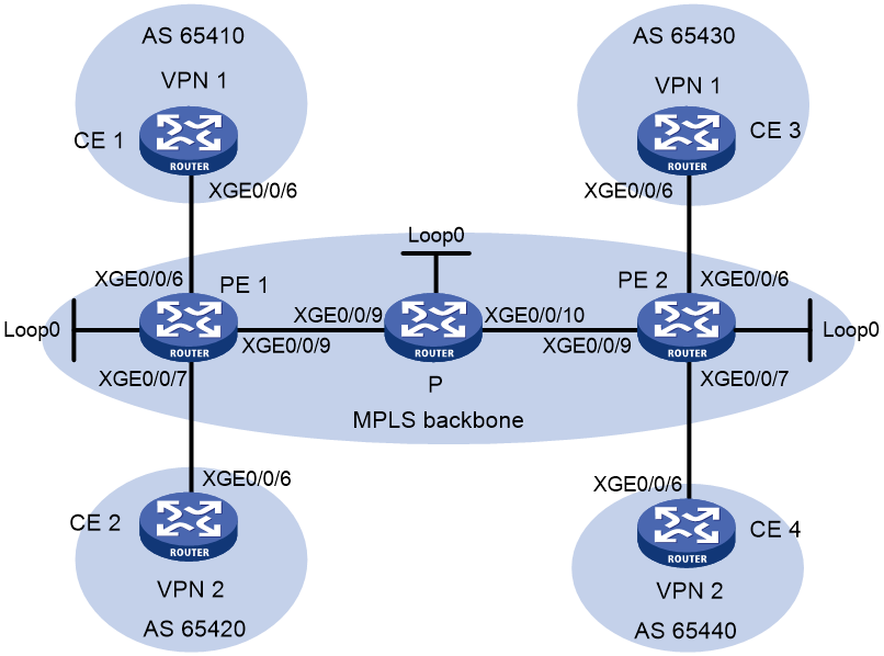
Table 1 Interface and IP address assignment
|
Device |
Interface |
IP address |
Device |
Interface |
IP address |
||||
|
CE 1 |
XGE0/0/6 |
2001:1::1/96 |
P |
Loop0 |
2.2.2.9/32 |
|
|||
|
PE 1 |
Loop0 |
1.1.1.9/32 |
|
XGE0/0/9 |
172.1.1.2/24 |
|
|||
|
|
XGE0/0/6 |
2001:1::2/96 |
|
XGE0/0/10 |
172.2.1.1/24 |
|
|||
|
|
XGE0/0/7 |
2001:2::2/96 |
PE 2 |
Loop0 |
3.3.3.9/32 |
|
|||
|
|
XGE0/0/9 |
172.1.1.1/24 |
|
XGE0/0/6 |
2001:3::2/96 |
|
|||
|
CE 2 |
XGE0/0/6 |
2001:2::1/96 |
|
XGE0/0/7 |
2001:4::2/96 |
|
|||
|
CE 3 |
XGE0/0/6 |
2001:3::1/96 |
|
XGE0/0/9 |
172.2.1.2/24 |
|
|||
|
CE 4 |
XGE0/0/6 |
2001:4::1/96 |
|
|
|
|
|||
Procedure
1. Configure OSPF on the MPLS backbone to ensure IP connectivity among the PEs and the P router:
# Configure PE 1.
<PE1> system-view
[PE1] interface loopback 0
[PE1-LoopBack0] ip address 1.1.1.9 32
[PE1-LoopBack0] quit
[PE1] interface ten-gigabitethernet 0/0/9
[PE1-Ten-GigabitEthernet0/0/9] ip address 172.1.1.1 24
[PE1-Ten-GigabitEthernet0/0/9] quit
[PE1] ospf
[PE1-ospf-1] area 0
[PE1-ospf-1-area-0.0.0.0] network 172.1.1.0 0.0.0.255
[PE1-ospf-1-area-0.0.0.0] network 1.1.1.9 0.0.0.0
[PE1-ospf-1-area-0.0.0.0] quit
[PE1-ospf-1] quit
# Configure the P router.
<P> system-view
[P] interface loopback 0
[P-LoopBack0] ip address 2.2.2.9 32
[P-LoopBack0] quit
[P] interface ten-gigabitethernet 0/0/9
[P-Ten-GigabitEthernet0/0/9] ip address 172.1.1.2 24
[P-Ten-GigabitEthernet0/0/9] quit
[P] interface ten-gigabitethernet 0/0/10
[P-Ten-GigabitEthernet0/0/10] ip address 172.2.1.1 24
[P-Ten-GigabitEthernet0/0/10] quit
[P] ospf
[P-ospf-1] area 0
[P-ospf-1-area-0.0.0.0] network 172.1.1.0 0.0.0.255
[P-ospf-1-area-0.0.0.0] network 172.2.1.0 0.0.0.255
[P-ospf-1-area-0.0.0.0] network 2.2.2.9 0.0.0.0
[P-ospf-1-area-0.0.0.0] quit
[P-ospf-1] quit
# Configure PE 2.
<PE2> system-view
[PE2] interface loopback 0
[PE2-LoopBack0] ip address 3.3.3.9 32
[PE2-LoopBack0] quit
[PE2] interface ten-gigabitethernet 0/0/9
[PE2-Ten-GigabitEthernet0/0/9] ip address 172.2.1.2 24
[PE2-Ten-GigabitEthernet0/0/9] quit
[PE2] ospf
[PE2-ospf-1] area 0
[PE2-ospf-1-area-0.0.0.0] network 172.2.1.0 0.0.0.255
[PE2-ospf-1-area-0.0.0.0] network 3.3.3.9 0.0.0.0
[PE2-ospf-1-area-0.0.0.0] quit
[PE2-ospf-1] quit
# Execute the display ospf peer command to verify that OSPF adjacencies in Full state have been established between PE 1, P, and PE 2. Execute the display ip routing-table command to verify that the PEs have learned the routes to the loopback interfaces of each other. (Details not shown.)
2. Configure basic MPLS and enable MPLS LDP on the MPLS backbone to establish LDP LSPs:
# Configure PE 1.
[PE1] mpls lsr-id 1.1.1.9
[PE1] mpls ldp
[PE1-ldp] quit
[PE1] interface ten-gigabitethernet 0/0/9
[PE1-Ten-GigabitEthernet0/0/9] mpls enable
[PE1-Ten-GigabitEthernet0/0/9] mpls ldp enable
[PE1-Ten-GigabitEthernet0/0/9] quit
# Configure the P router.
[P] mpls lsr-id 2.2.2.9
[P] mpls ldp
[P-ldp] quit
[P] interface ten-gigabitethernet 0/0/9
[P-Ten-GigabitEthernet0/0/9] mpls enable
[P-Ten-GigabitEthernet0/0/9] mpls ldp enable
[P-Ten-GigabitEthernet0/0/9] quit
[P] interface ten-gigabitethernet 0/0/10
[P-Ten-GigabitEthernet0/0/10] mpls enable
[P-Ten-GigabitEthernet0/0/10] mpls ldp enable
[P-Ten-GigabitEthernet0/0/10] quit
# Configure PE 2.
[PE2] mpls lsr-id 3.3.3.9
[PE2] mpls ldp
[PE2-ldp] quit
[PE2] interface ten-gigabitethernet 0/0/9
[PE2-Ten-GigabitEthernet0/0/9] mpls enable
[PE2-Ten-GigabitEthernet0/0/9] mpls ldp enable
[PE2-Ten-GigabitEthernet0/0/9] quit
# Execute the display mpls ldp peer command to verify that LDP sessions in Operational state have been established between PE 1, P, and PE 2. Execute the display mpls ldp lsp command to verify that the LSPs have been established by LDP. (Details not shown.)
3. Configure IPv6 VPN instances on the PEs to allow CE access:
# Configure PE 1.
[PE1] ip vpn-instance vpn1
[PE1-vpn-instance-vpn1] route-distinguisher 100:1
[PE1-vpn-instance-vpn1] vpn-target 111:1
[PE1-vpn-instance-vpn1] quit
[PE1] ip vpn-instance vpn2
[PE1-vpn-instance-vpn2] route-distinguisher 100:2
[PE1-vpn-instance-vpn2] vpn-target 222:2
[PE1-vpn-instance-vpn2] quit
[PE1] interface ten-gigabitethernet 0/0/6
[PE1-Ten-GigabitEthernet0/0/6] ip binding vpn-instance vpn1
[PE1-Ten-GigabitEthernet0/0/6] ipv6 address 2001:1::2 96
[PE1-Ten-GigabitEthernet0/0/6] quit
[PE1] interface ten-gigabitethernet 0/0/7
[PE1-Ten-GigabitEthernet0/0/7] ip binding vpn-instance vpn2
[PE1-Ten-GigabitEthernet0/0/7] ipv6 address 2001:2::2 96
[PE1-Ten-GigabitEthernet0/0/7] quit
# Configure PE 2.
[PE2] ip vpn-instance vpn1
[PE2-vpn-instance-vpn1] route-distinguisher 200:1
[PE2-vpn-instance-vpn1] vpn-target 111:1
[PE2-vpn-instance-vpn1] quit
[PE2] ip vpn-instance vpn2
[PE2-vpn-instance-vpn2] route-distinguisher 200:2
[PE2-vpn-instance-vpn2] vpn-target 222:2
[PE2-vpn-instance-vpn2] quit
[PE2] interface ten-gigabitethernet 0/0/6
[PE2-Ten-GigabitEthernet0/0/6] ip binding vpn-instance vpn1
[PE2-Ten-GigabitEthernet0/0/6] ipv6 address 2001:3::2 96
[PE2-Ten-GigabitEthernet0/0/6] quit
[PE2] interface ten-gigabitethernet 0/0/7
[PE2-Ten-GigabitEthernet0/0/7] ip binding vpn-instance vpn2
[PE2-Ten-GigabitEthernet0/0/7] ipv6 address 2001:4::2 96
[PE2-Ten-GigabitEthernet0/0/7] quit
# Configure IP addresses for the CEs according to Table 1. (Details not shown.)
# Execute the display ip vpn-instance command on the PEs to display information about the VPN instances.
# Use the ping command on the PEs to verify that the PEs can ping their attached CEs.
4. Establish EBGP peer relationships between the PEs and CEs to allow them to exchange VPN routes:
# Configure CE 1.
<CE1> system-view
[CE1] bgp 65410
[CE1-bgp-default] peer 2001:1::2 as-number 100
[CE1-bgp-default] address-family ipv6 unicast
[CE1-bgp-default-ipv6] peer 2001:1::2 enable
[CE1-bgp-default-ipv6] import-route direct
[CE1-bgp-default-ipv6] quit
[CE1-bgp-default] quit
# Configure the other CEs (CE 2 through CE 4) in the same way that CE 1 is configured. (Details not shown.)
# Configure PE 1.
[PE1] bgp 100
[PE1-bgp-default] ip vpn-instance vpn1
[PE1-bgp-default-vpn1] peer 2001:1::1 as-number 65410
[PE1-bgp-default-vpn1] address-family ipv6 unicast
[PE1-bgp-default-ipv6-vpn1] peer 2001:1::1 enable
[PE1-bgp-default-ipv6-vpn1] quit
[PE1-bgp-default-vpn1] quit
[PE1-bgp-default] ip vpn-instance vpn2
[PE1-bgp-default-vpn2] peer 2001:2::1 as-number 65420
[PE1-bgp-default-vpn2] address-family ipv6 unicast
[PE1-bgp-default-ipv6-vpn2] peer 2001:2::1 enable
[PE1-bgp-default-ipv6-vpn2] quit
[PE1-bgp-default-vpn2] quit
[PE1-bgp-default] quit
# Configure PE 2 in the same way that PE 1 is configured. (Details not shown.)
# Execute the display bgp peer ipv6 vpn-instance command on the PEs to verify that a BGP peer relationship in Established state has been established between a PE and a CE. (Details not shown.)
5. Configure an MP-IBGP peer relationship between the PEs:
# Configure PE 1.
[PE1] bgp 100
[PE1-bgp-default] peer 3.3.3.9 as-number 100
[PE1-bgp-default] peer 3.3.3.9 connect-interface loopback 0
[PE1-bgp-default] address-family vpnv6
[PE1-bgp-default-vpnv6] peer 3.3.3.9 enable
[PE1-bgp-default-vpnv6] quit
[PE1-bgp-default] quit
# Configure PE 2.
[PE2] bgp 100
[PE2-bgp-default] peer 1.1.1.9 as-number 100
[PE2-bgp-default] peer 1.1.1.9 connect-interface loopback 0
[PE2-bgp-default] address-family vpnv6
[PE2-bgp-default-vpnv6] peer 1.1.1.9 enable
[PE2-bgp-default-vpnv6] quit
[PE2-bgp-default] quit
# Execute the display bgp peer vpnv6 command on the PEs to verify that a BGP peer relationship in Established state has been established between the PEs. (Details not shown.)
Verifying the configuration
# Execute the display ipv6 routing-table vpn-instance command on the PEs.
[PE1] display ipv6 routing-table vpn-instance vpn1
Destinations : 6 Routes : 6
Destination: ::1/128 Protocol : Direct
NextHop : ::1 Preference: 0
Interface : InLoop0 Cost : 0
Destination: 2001:1::/96 Protocol : Direct
NextHop : :: Preference: 0
Interface : XGE0/0/6 Cost : 0
Destination: 2001:1::2/128 Protocol : Direct
NextHop : ::1 Preference: 0
Interface : InLoop0 Cost : 0
Destination: 2001:3::/96 Protocol : BGP4+
NextHop : ::FFFF:3.3.3.9 Preference: 255
Interface : XGE0/0/9 Cost : 0
Destination: FE80::/10 Protocol : Direct
NextHop : :: Preference: 0
Interface : NULL0 Cost : 0
Destination: FF00::/8 Protocol : Direct
NextHop : :: Preference: 0
Interface : NULL0 Cost : 0
[PE1] display ipv6 routing-table vpn-instance vpn2
Destinations : 6 Routes : 6
Destination: ::1/128 Protocol : Direct
NextHop : ::1 Preference: 0
Interface : InLoop0 Cost : 0
Destination: 2001:2::/96 Protocol : Direct
NextHop : :: Preference: 0
Interface : XGE0/0/7 Cost : 0
Destination: 2001:2::2/128 Protocol : Direct
NextHop : ::1 Preference: 0
Interface : InLoop0 Cost : 0
Destination: 2001:4::/96 Protocol : BGP4+
NextHop : ::FFFF:3.3.3.9 Preference: 255
Interface : XGE0/0/9 Cost : 0
Destination: FE80::/10 Protocol : Direct
NextHop : :: Preference: 0
Interface : NULL0 Cost : 0
Destination: FF00::/8 Protocol : Direct
NextHop : :: Preference: 0
Interface : NULL0 Cost : 0
The output shows that PE 1 has routes to the remote CEs. Output on PE 2 is similar.
# Verify that CEs of the same VPN can ping each other, whereas those of different VPNs cannot. For example, CE 1 can ping CE 3 (2001:3::1), but cannot ping CE 4 (2001:4::1). (Details not shown.)
Example: Configuring an IPv6 MPLS L3VPN over a GRE tunnel
Network configuration
CE 1 and CE 2 belong to VPN 1. The PEs support MPLS, while the P router does not support MPLS and provides only IP features.
On the backbone, use a GRE tunnel to encapsulate and forward packets for IPv6 MPLS L3VPN.
Configure tunnel policies on the PEs, and specify the tunnel type for VPN traffic as GRE.
Figure 4 Network diagram
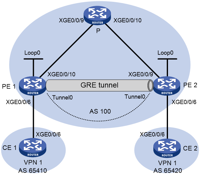
Table 2 Interface and IP address assignment
|
Device |
Interface |
IP address |
Device |
Interface |
IP address |
|
CE 1 |
XGE0/0/6 |
2001:1::1/96 |
P |
XGE0/0/9 |
172.1.1.2/24 |
|
PE 1 |
Loop0 |
1.1.1.9/32 |
|
XGE0/0/10 |
172.2.1.1/24 |
|
|
XGE0/0/6 |
2001:1::2/96 |
PE 2 |
Loop0 |
2.2.2.9/32 |
|
|
XGE0/0/10 |
172.1.1.1/24 |
|
XGE0/0/6 |
2001:2::2/96 |
|
|
Tunnel0 |
20.1.1.1/24 |
|
XGE0/0/9 |
172.2.1.2/24 |
|
CE 2 |
XGE0/0/6 |
2001:2::1/96 |
|
Tunnel0 |
20.1.1.2/24 |
Procedure
1. Configure an IGP on the MPLS backbone to ensure IP connectivity among the PEs and the P router.
This example uses OSPF. (Details not shown.)
# Execute the display ospf peer command to verify that OSPF adjacencies in Full state have been established between PE 1, P, and PE 2. Execute the display ip routing-table command to verify that the PEs have learned the routes to the loopback interfaces of each other. (Details not shown.)
2. Configure basic MPLS on the PEs:
# Configure PE 1.
<PE1> system-view
[PE1] mpls lsr-id 1.1.1.9
# Configure PE 2.
<PE2> system-view
[PE2] mpls lsr-id 2.2.2.9
3. Configure VPN instances on the PEs to allow CE access, and apply tunnel policies to the VPN instances to use a GRE tunnel for VPN packet forwarding:
# Configure PE 1.
[PE1] tunnel-policy gre1
[PE1-tunnel-policy-gre1] tunnel select-seq gre load-balance-number 1
[PE1-tunnel-policy-gre1] quit
[PE1] ip vpn-instance vpn1
[PE1-vpn-instance-vpn1] route-distinguisher 100:1
[PE1-vpn-instance-vpn1] vpn-target 100:1 both
[PE1-vpn-instance-vpn1] tnl-policy gre1
[PE1-vpn-instance-vpn1] quit
[PE1] interface ten-gigabitethernet 0/0/6
[PE1-Ten-GigabitEthernet0/0/6] ip binding vpn-instance vpn1
[PE1-Ten-GigabitEthernet0/0/6] ipv6 address 2001:1::2 96
[PE1-Ten-GigabitEthernet0/0/6] quit
# Configure PE 2.
[PE2] tunnel-policy gre1
[PE2-tunnel-policy-gre1] tunnel select-seq gre load-balance-number 1
[PE2-tunnel-policy-gre1] quit
[PE2] ip vpn-instance vpn1
[PE2-vpn-instance-vpn1] route-distinguisher 100:2
[PE2-vpn-instance-vpn1] vpn-target 100:1 both
[PE2-vpn-instance-vpn1] tnl-policy gre1
[PE2-vpn-instance-vpn1] quit
[PE2] interface ten-gigabitethernet 0/0/6
[PE2-Ten-GigabitEthernet0/0/6] ip binding vpn-instance vpn1
[PE2-Ten-GigabitEthernet0/0/6] ipv6 address 2001:2::2 96
[PE2-Ten-GigabitEthernet0/0/6] quit
# Configure CE 1.
<CE1> system-view
[CE1] interface ten-gigabitethernet 0/0/6
[CE1-Ten-GigabitEthernet0/0/6] ipv6 address 2001:1::1 96
[CE1-Ten-GigabitEthernet0/0/6] quit
# Configure CE 2.
<CE2> system-view
[CE2] interface ten-gigabitethernet 0/0/6
[CE2-Ten-GigabitEthernet0/0/6] ipv6 address 2001:2::1 96
[CE2-Ten-GigabitEthernet0/0/6] quit
# Execute the display ip vpn-instance command on the PEs to display information about the VPN instance.
# Use the ping command on the PEs to verify that the PEs can ping their attached CEs.
4. Establish EBGP peer relationships between PEs and CEs to allow them to exchange VPN routes:
# Configure CE 1.
[CE1] bgp 65410
[CE1-bgp-default] peer 2001:1::2 as-number 100
[CE1-bgp-default] address-family ipv6 unicast
[CE1-bgp-default-ipv6] peer 2001:1::2 enable
[CE1-bgp-default-ipv6] import-route direct
[CE1-bgp-default-ipv6] quit
# Configure PE 1.
[PE1] bgp 100
[PE1-bgp-default] ip vpn-instance vpn1
[PE1-bgp-default-vpn1] peer 2001:1::1 as-number 65410
[PE1-bgp-default-vpn1] address-family ipv6 unicast
[PE1-bgp-default-ipv6-vpn1] peer 2001:1::1 enable
[PE1-bgp-default-ipv6-vpn1] quit
[PE1-bgp-default-vpn1] quit
[PE1-bgp-default] quit
# Configure CE 2 and PE 2 in the same way that CE 1 and PE 1 are configured. (Details not shown.)
# Execute the display bgp peer ipv6 vpn-instance command on the PEs to verify that a BGP peer relationship in Established state has been established between a PE and a CE. (Details not shown.)
5. Configure an MP-IBGP peer relationship between the PEs:
# Configure PE 1.
[PE1] bgp 100
[PE1-bgp-default] peer 2.2.2.9 as-number 100
[PE1-bgp-default] peer 2.2.2.9 connect-interface loopback 0
[PE1-bgp-default] address-family vpnv6
[PE1-bgp-default-vpnv6] peer 2.2.2.9 enable
[PE1-bgp-default-vpnv6] quit
[PE1-bgp-default] quit
# Configure PE 2 in the same way that PE 1 is configured. (Details not shown.)
# Execute the display bgp peer vpnv6 command on the PEs to verify that a BGP peer relationship in Established state has been established between the PEs. (Details not shown.)
6. Configure a GRE tunnel:
# Configure PE 1.
[PE1] interface tunnel 0 mode gre
[PE1-Tunnel0] source loopback 0
[PE1-Tunnel0] destination 2.2.2.9
[PE1-Tunnel0] ip address 20.1.1.1 24
[PE1-Tunnel0] mpls enable
[PE1-Tunnel0] quit
# Configure PE 2.
[PE2] interface tunnel 0 mode gre
[PE2-Tunnel0] source loopback 0
[PE2-Tunnel0] destination 1.1.1.9
[PE2-Tunnel0] ip address 20.1.1.2 24
[PE2-Tunnel0] mpls enable
[PE2-Tunnel0] quit
Verifying the configuration
# Verify that the CEs have learned the route to each other and can ping each other. (Details not shown.)
Example: Configuring a hub-spoke network
Network configuration
The Spoke-CEs cannot communicate directly. They can communicate only through the Hub-CE.
Configure EBGP between the Spoke-CEs and Spoke-PEs and between the Hub-CE and Hub-PE to exchange VPN routing information.
Configure OSPF between the Spoke-PEs and Hub-PE to implement communication between the PEs. Configure MP-IBGP between the Spoke-PEs and Hub-PE to exchange VPN routing information.
Figure 5 Network diagram

Table 3 Interface and IP address assignment
|
Device |
Interface |
IP address |
Device |
Interface |
IP address |
|
Spoke-CE 1 |
XGE0/0/6 |
11::1/64 |
Hub-CE |
XGE0/0/6 |
13::1/64 |
|
Spoke-PE 1 |
Loop0 |
1.1.1.9/32 |
|
XGE0/0/7 |
14::1/64 |
|
|
XGE0/0/6 |
11::2/64 |
Hub-PE |
Loop0 |
2.2.2.9/32 |
|
|
XGE0/0/9 |
172.1.1.1/24 |
|
XGE0/0/9 |
172.1.1.2/24 |
|
Spoke-CE 2 |
XGE0/0/6 |
12::1/64 |
|
XGE0/0/10 |
172.2.1.2/24 |
|
Spoke-PE 2 |
Loop0 |
3.3.3.9/32 |
|
XGE0/0/6 |
13::2/64 |
|
|
XGE0/0/6 |
12::2/64 |
|
XGE0/0/7 |
14::2/64 |
|
|
XGE0/0/9 |
172.2.1.1/24 |
|
|
|
Procedure
1. Configure an IGP on the MPLS backbone to ensure IP connectivity within the backbone:
# Configure Spoke-PE 1.
<Spoke-PE1> system-view
[Spoke-PE1] interface loopback 0
[Spoke-PE1-LoopBack0] ip address 1.1.1.9 32
[Spoke-PE1-LoopBack0] quit
[Spoke-PE1] interface ten-gigabitethernet 0/0/9
[Spoke-PE1-Ten-GigabitEthernet0/0/9] ip address 172.1.1.1 24
[Spoke-PE1-Ten-GigabitEthernet0/0/9] quit
[Spoke-PE1] ospf
[Spoke-PE1-ospf-1] area 0
[Spoke-PE1-ospf-1-area-0.0.0.0] network 172.1.1.0 0.0.0.255
[Spoke-PE1-ospf-1-area-0.0.0.0] network 1.1.1.9 0.0.0.0
[Spoke-PE1-ospf-1-area-0.0.0.0] quit
[Spoke-PE1-ospf-1] quit
# Configure Spoke-PE 2.
<Spoke-PE2> system-view
[Spoke-PE2] interface loopback 0
[Spoke-PE2-LoopBack0] ip address 3.3.3.9 32
[Spoke-PE2-LoopBack0] quit
[Spoke-PE2] interface ten-gigabitethernet 0/0/9
[Spoke-PE2-Ten-GigabitEthernet0/0/9] ip address 172.1.1.1 24
[Spoke-PE2-Ten-GigabitEthernet0/0/9] quit
[Spoke-PE2] ospf
[Spoke-PE2-ospf-1] area 0
[Spoke-PE2-ospf-1-area-0.0.0.0] network 172.2.1.0 0.0.0.255
[Spoke-PE2-ospf-1-area-0.0.0.0] network 3.3.3.9 0.0.0.0
[Spoke-PE2-ospf-1-area-0.0.0.0] quit
[Spoke-PE2-ospf-1] quit
# Configure Hub-PE.
<Hub-PE> system-view
[Hub-PE] interface loopback 0
[Hub-PE-LoopBack0] ip address 2.2.2.9 32
[Hub-PE-LoopBack0] quit
[Hub-PE] interface ten-gigabitethernet 0/0/9
[Hub-PE-Ten-GigabitEthernet0/0/9] ip address 172.1.1.2 24
[Hub-PE-Ten-GigabitEthernet0/0/9] quit
[Hub-PE] interface ten-gigabitethernet 0/0/10
[Hub-PE-Ten-GigabitEthernet0/0/10] ip address 172.2.1.2 24
[Hub-PE-Ten-GigabitEthernet0/0/10] quit
[Hub-PE] ospf
[Hub-PE-ospf-1] area 0
[Hub-PE-ospf-1-area-0.0.0.0] network 172.1.1.0 0.0.0.255
[Hub-PE-ospf-1-area-0.0.0.0] network 172.2.1.0 0.0.0.255
[Hub-PE-ospf-1-area-0.0.0.0] network 2.2.2.9 0.0.0.0
[Hub-PE-ospf-1-area-0.0.0.0] quit
[Hub-PE-ospf-1] quit
# Execute the display ospf peer command on the PEs to verify that OSPF adjacencies in Full state have been established between the PEs. Execute the display ip routing-table command on the PEs to verify that the PEs have learned the routes to the loopback interfaces of each other. (Details not shown.)
2. Configure basic MPLS and MPLS LDP on the MPLS backbone to establish LDP LSPs:
# Configure Spoke-PE 1.
[Spoke-PE1] mpls lsr-id 1.1.1.9
[Spoke-PE1] mpls ldp
[Spoke-PE1-ldp] quit
[Spoke-PE1] interface ten-gigabitethernet 0/0/9
[Spoke-PE1-Ten-GigabitEthernet0/0/9] mpls enable
[Spoke-PE1-Ten-GigabitEthernet0/0/9] mpls ldp enable
[Spoke-PE1-Ten-GigabitEthernet0/0/9] quit
# Configure Spoke-PE 2.
[Spoke-PE2] mpls lsr-id 3.3.3.9
[Spoke-PE2] mpls ldp
[Spoke-PE2-ldp] quit
[Spoke-PE2] interface ten-gigabitethernet 0/0/9
[Spoke-PE2-Ten-GigabitEthernet0/0/9] mpls enable
[Spoke-PE2-Ten-GigabitEthernet0/0/9] mpls ldp enable
[Spoke-PE2-Ten-GigabitEthernet0/0/9] quit
# Configure Hub-PE.
[Hub-PE] mpls lsr-id 2.2.2.9
[Hub-PE] mpls ldp
[Hub-PE-ldp] quit
[Hub-PE] interface ten-gigabitethernet 0/0/9
[Hub-PE-Ten-GigabitEthernet0/0/9] mpls enable
[Hub-PE-Ten-GigabitEthernet0/0/9] mpls ldp enable
[Hub-PE-Ten-GigabitEthernet0/0/9] quit
[Hub-PE] interface ten-gigabitethernet 0/0/10
[Hub-PE-Ten-GigabitEthernet0/0/10] mpls enable
[Hub-PE-Ten-GigabitEthernet0/0/10] mpls ldp enable
[Hub-PE-Ten-GigabitEthernet0/0/10] quit
# Execute the display mpls ldp peer command on the PEs to verify that LDP sessions in Operational state have been established between the PEs. Execute the display mpls ldp lsp command on the PEs to verify that the LSPs have been established by LDP. (Details not shown.)
3. Configure VPN instances on the Spoke-PEs and Hub-PE:
# Configure Spoke-PE 1.
[Spoke-PE1] ip vpn-instance vpn1
[Spoke-PE1-vpn-instance-vpn1] route-distinguisher 100:1
[Spoke-PE1-vpn-instance-vpn1] vpn-target 111:1 import-extcommunity
[Spoke-PE1-vpn-instance-vpn1] vpn-target 222:2 export-extcommunity
[Spoke-PE1-vpn-instance-vpn1] quit
[Spoke-PE1] interface ten-gigabitethernet 0/0/6
[Spoke-PE1-Ten-GigabitEthernet0/0/6] ip binding vpn-instance vpn1
[Spoke-PE1-Ten-GigabitEthernet0/0/6] ip address 11::2 24
[Spoke-PE1-Ten-GigabitEthernet0/0/6] quit
# Configure Spoke-PE 2.
[Spoke-PE2] ip vpn-instance vpn1
[Spoke-PE2-vpn-instance-vpn1] route-distinguisher 100:2
[Spoke-PE2-vpn-instance-vpn1] vpn-target 111:1 import-extcommunity
[Spoke-PE2-vpn-instance-vpn1] vpn-target 222:2 export-extcommunity
[Spoke-PE2-vpn-instance-vpn1] quit
[Spoke-PE2] interface ten-gigabitethernet 0/0/6
[Spoke-PE2-Ten-GigabitEthernet0/0/6] ip binding vpn-instance vpn1
[Spoke-PE2-Ten-GigabitEthernet0/0/6] ip address 12::2 24
[Spoke-PE2-Ten-GigabitEthernet0/0/6] quit
# Configure Hub-PE.
[Hub-PE] ip vpn-instance vpn1-in
[Hub-PE-vpn-instance-vpn1-in] route-distinguisher 100:3
[Hub-PE-vpn-instance-vpn1-in] vpn-target 222:2 import-extcommunity
[Hub-PE-vpn-instance-vpn1-in] quit
[Hub-PE] ip vpn-instance vpn1-out
[Hub-PE-vpn-instance-vpn1-out] route-distinguisher 100:4
[Hub-PE-vpn-instance-vpn1-out] vpn-target 111:1 export-extcommunity
[Hub-PE-vpn-instance-vpn1-out] quit
[Hub-PE] interface ten-gigabitethernet 0/0/6
[Hub-PE-Ten-GigabitEthernet0/0/6] ip binding vpn-instance vpn1-in
[Hub-PE-Ten-GigabitEthernet0/0/6] ip address 13::2 24
[Hub-PE-Ten-GigabitEthernet0/0/6] quit
[Hub-PE] interface ten-gigabitethernet 0/0/7
[Hub-PE-Ten-GigabitEthernet0/0/7] ip binding vpn-instance vpn1-out
[Hub-PE-Ten-GigabitEthernet0/0/7] ip address 14::2 24
[Hub-PE-Ten-GigabitEthernet0/0/7] quit
# Configure IP addresses for the CEs according to Table 3. (Details not shown.)
# Execute the display ip vpn-instance command on the PEs to display the VPN instance configuration.
# Use the ping command on the PEs to verify that the PEs can ping their attached CEs.
4. Establish EBGP peer relationships between the PEs and CEs, and redistribute VPN routes into BGP:
# Configure Spoke-CE 1.
<Spoke-CE1> system-view
[Spoke-CE1] bgp 65410
[Spoke-CE1-bgp-default] peer 11::2 as-number 100
[Spoke-CE1-bgp-default] address-family ipv6
[Spoke-CE1-bgp-default-ipv6] peer 11::2 enable
[Spoke-CE1-bgp-default-ipv6] import-route direct
[Spoke-CE1-bgp-default-ipv6] quit
[Spoke-CE1-bgp-default] quit
# Configure Spoke-CE 2.
<Spoke-CE2> system-view
[Spoke-CE2] bgp 65420
[Spoke-CE2-bgp-default] peer 12::2 as-number 100
[Spoke-CE2-bgp-default] address-family ipv6
[Spoke-CE2-bgp-default-ipv6] peer 12::2 enable
[Spoke-CE2-bgp-default-ipv6] import-route direct
[Spoke-CE2-bgp-default-ipv6] quit
[Spoke-CE2-bgp-default] quit
# Configure Hub-CE.
<Hub-CE> system-view
[Hub-CE] bgp 65430
[Hub-CE-bgp-default] peer 13::2 as-number 100
[Hub-CE-bgp-default] peer 14::2 as-number 100
[Hub-CE-bgp-default] address-family ipv6
[Hub-CE-bgp-default-ipv6] peer 13::2 enable
[Hub-CE-bgp-default-ipv6] peer 14::2 enable
[Hub-CE-bgp-default-ipv6] import-route direct
[Hub-CE-bgp-default-ipv6] quit
[Hub-CE-bgp-default] quit
# Configure Spoke-PE 1.
[Spoke-PE1] bgp 100
[Spoke-PE1-bgp-default] ip vpn-instance vpn1
[Spoke-PE1-bgp-default-vpn1] peer 11::1 as-number 65410
[Spoke-PE1-bgp-default-vpn1] address-family ipv6
[Spoke-PE1-bgp-default-ipv6-vpn1] peer 11::1 enable
[Spoke-PE1-bgp-default-ipv6-vpn1] quit
[Spoke-PE1-bgp-default-vpn1] quit
[Spoke-PE1-bgp-default] quit
# Configure Spoke-PE 2.
[Spoke-PE2] bgp 100
[Spoke-PE2-bgp-default] ip vpn-instance vpn1
[Spoke-PE2-bgp-default-vpn1] peer 12::1 as-number 65420
[Spoke-PE2-bgp-default-vpn1] address-family ipv6
[Spoke-PE2-bgp-default-ipv6-vpn1] peer 12::1 enable
[Spoke-PE2-bgp-default-ipv6-vpn1] quit
[Spoke-PE2-bgp-default-vpn1] quit
[Spoke-PE2-bgp-default] quit
# Configure Hub-PE.
[Hub-PE] bgp 100
[Hub-PE-bgp-default] ip vpn-instance vpn1-in
[Hub-PE-bgp-default-vpn1-in] peer 13::1 as-number 65430
[Hub-PE-bgp-default-vpn1-in] address-family ipv6
[Hub-PE-bgp-default-ipv6-vpn1-in] peer 13::1 enable
[Hub-PE-bgp-default-ipv6-vpn1-in] quit
[Hub-PE-bgp-default-vpn1-in] quit
[Hub-PE-bgp-default] ip vpn-instance vpn1-out
[Hub-PE-bgp-default-vpn1-out] peer 14::1 as-number 65430
[Hub-PE-bgp-default-vpn1-out] address-family ipv6
[Hub-PE-bgp-default-ipv6-vpn1-out] peer 14::1 enable
[Hub-PE-bgp-default-ipv6-vpn1-out] peer 14::1 allow-as-loop 2
[Hub-PE-bgp-default-ipv6-vpn1-out] quit
[Hub-PE-bgp-default-vpn1-out] quit
[Hub-PE-bgp-default] quit
# Execute the display bgp peer ipv6 vpn-instance command on the PEs to verify that a BGP peer relationship in Established state has been established between a PE and a CE. (Details not shown.)
5. Establish an MP-IBGP peer relationship between the Spoke-PEs and Hub-PE:
# Configure Spoke-PE 1.
[Spoke-PE1] bgp 100
[Spoke-PE1-bgp-default] peer 2.2.2.9 as-number 100
[Spoke-PE1-bgp-default] peer 2.2.2.9 connect-interface loopback 0
[Spoke-PE1-bgp-default] address-family vpnv6
[Spoke-PE1-bgp-default-vpnv6] peer 2.2.2.9 enable
[Spoke-PE1-bgp-default-vpnv6] quit
[Spoke-PE1-bgp-default] quit
# Configure Spoke-PE 2.
[Spoke-PE2] bgp 100
[Spoke-PE2-bgp-default] peer 2.2.2.9 as-number 100
[Spoke-PE2-bgp-default] peer 2.2.2.9 connect-interface loopback 0
[Spoke-PE2-bgp-default] address-family vpnv6
[Spoke-PE2-bgp-default-vpnv6] peer 2.2.2.9 enable
[Spoke-PE2-bgp-default-vpnv6] quit
[Spoke-PE2-bgp-default] quit
# Configure Hub-PE.
[Hub-PE] bgp 100
[Hub-PE-bgp-default] peer 1.1.1.9 as-number 100
[Hub-PE-bgp-default] peer 1.1.1.9 connect-interface loopback 0
[Hub-PE-bgp-default] peer 3.3.3.9 as-number 100
[Hub-PE-bgp-default] peer 3.3.3.9 connect-interface loopback 0
[Hub-PE-bgp-default] address-family vpnv6
[Hub-PE-bgp-default-vpnv6] peer 1.1.1.9 enable
[Hub-PE-bgp-default-vpnv6] peer 3.3.3.9 enable
[Hub-PE-bgp-default-vpnv6] quit
[Hub-PE-bgp-default] quit
# Execute the display bgp peer vpnv6 command on the PEs to verify that a BGP peer relationship in Established state has been established between the PEs. (Details not shown.)
Verifying the configuration
# Verify that Spoke-CE 1 and Spoke-CE 2 can ping each other. The TTL value indicates that traffic from Spoke-CE 1 to Spoke-CE 2 passes six hops (64-59+1) and is forwarded through Hub-CE. This example uses Spoke-CE 1.
[Spoke-CE1] ping ipv6 12::1
Ping6(56 bytes) 11::1 --> 12::1, press CTRL_C to break
56 bytes from 12::1, icmp_seq=0 hlim=59 time=0.000 ms
56 bytes from 12::1, icmp_seq=1 hlim=59 time=1.000 ms
56 bytes from 12::1, icmp_seq=2 hlim=59 time=0.000 ms
56 bytes from 12::1, icmp_seq=3 hlim=59 time=1.000 ms
56 bytes from 12::1, icmp_seq=4 hlim=59 time=0.000 ms
--- Ping6 statistics for 12::1 ---
5 packet(s) transmitted, 5 packet(s) received, 0.0% packet loss
round-trip min/avg/max/std-dev = 0.000/0.400/1.000/0.490 ms
Example: Configuring IPv6 MPLS L3VPN inter-AS option A
Network configuration
CE 1 and CE 2 belong to the same VPN. CE 1 accesses the network through PE 1 in AS 100 and CE 2 accesses the network through PE 2 in AS 200.
Configure IPv6 MPLS L3VPN inter-AS option A, and use VRF-to-VRF method to manage VPN routes.
Run OSPF on the MPLS backbone of each AS.
Figure 6 Network diagram
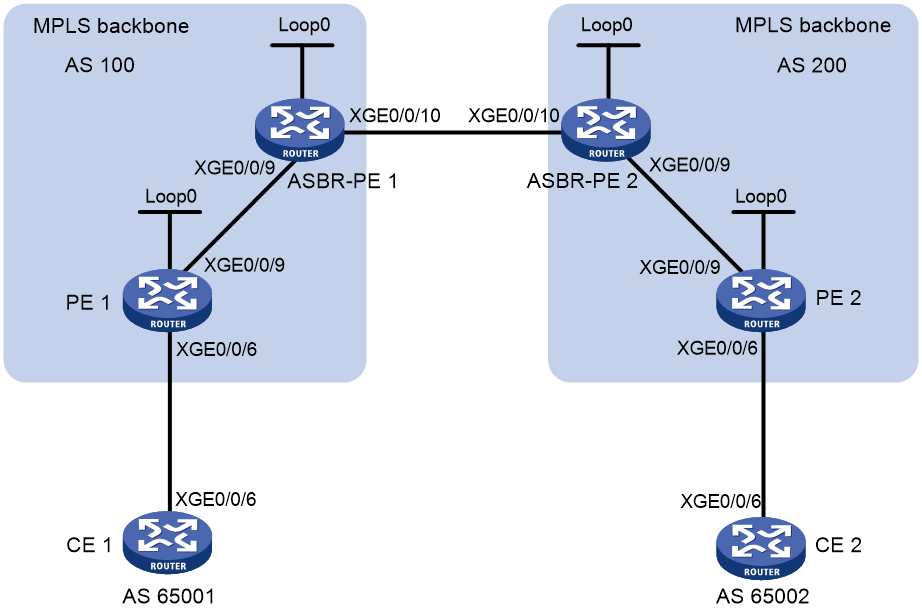
Table 4 Interface and IP address assignment
|
Device |
Interface |
IP address |
Device |
Interface |
IP address |
|
CE 1 |
XGE0/0/6 |
2001:1::1/96 |
CE 2 |
XGE0/0/6 |
2001:2::1/96 |
|
PE 1 |
Loop0 |
1.1.1.9/32 |
PE 2 |
Loop0 |
4.4.4.9/32 |
|
|
XGE0/0/6 |
2001:1::2/96 |
|
XGE0/0/6 |
2001:2::2/96 |
|
|
XGE0/0/9 |
172.1.1.2/24 |
|
XGE0/0/9 |
162.1.1.2/24 |
|
ASBR-PE1 |
Loop0 |
2.2.2.9/32 |
ASBR-PE2 |
Loop0 |
3.3.3.9/32 |
|
|
XGE0/0/9 |
172.1.1.1/24 |
|
XGE0/0/9 |
162.1.1.1/24 |
|
|
XGE0/0/10 |
2002:1::1/96 |
|
XGE0/0/10 |
2002:1::2/96 |
Restrictions and guidelines
For the same VPN, the route targets for the VPN instance on the PE must match those for the VPN instance on the ASBR-PE in the same AS. This is not required for PEs in different ASs.
Procedure
1. Configure an IGP on each MPLS backbone to ensure IP connectivity within the backbone.
This example uses OSPF. Be sure to advertise the route to the 32-bit loopback interface address of each router through OSPF. Use the loopback interface address of a router as the router's LSR ID. (Details not shown.)
# Execute the display ospf peer command to verify that each ASBR-PE has established an OSPF adjacency in Full state with the PE in the same AS, and that the PEs and ASBR-PEs in the same AS have learned the routes to the loopback interfaces of each other. Execute the ping command to verify that the PEs and ASBR-PEs in the same AS can ping each other. (Details not shown.)
2. Configure basic MPLS and enable MPLS LDP on each MPLS backbone to establish LDP LSPs:
# Configure basic MPLS on PE 1, and enable MPLS LDP for both PE 1 and the interface connected to ASBR-PE 1.
<PE1> system-view
[PE1] mpls lsr-id 1.1.1.9
[PE1] mpls ldp
[PE1-ldp] quit
[PE1] interface ten-gigabitethernet 0/0/9
[PE1-Ten-GigabitEthernet0/0/9] mpls enable
[PE1-Ten-GigabitEthernet0/0/9] mpls ldp enable
[PE1-Ten-GigabitEthernet0/0/9] quit
# Configure basic MPLS on ASBR-PE 1, and enable MPLS LDP for both ASBR-PE 1 and the interface connected to PE 1.
<ASBR-PE1> system-view
[ASBR-PE1] mpls lsr-id 2.2.2.9
[ASBR-PE1] mpls ldp
[ASBR-PE1-ldp] quit
[ASBR-PE1] interface ten-gigabitethernet 0/0/9
[ASBR-PE1-Ten-GigabitEthernet0/0/9] mpls enable
[ASBR-PE1-Ten-GigabitEthernet0/0/9] mpls ldp enable
[ASBR-PE1-Ten-GigabitEthernet0/0/9] quit
# Configure basic MPLS on ASBR-PE 2, and enable MPLS LDP for both ASBR-PE 2 and the interface connected to PE 2.
<ASBR-PE2> system-view
[ASBR-PE2] mpls lsr-id 3.3.3.9
[ASBR-PE2] mpls ldp
[ASBR-PE2-ldp] quit
[ASBR-PE2] interface ten-gigabitethernet 0/0/9
[ASBR-PE2-Ten-GigabitEthernet0/0/9] mpls enable
[ASBR-PE2-Ten-GigabitEthernet0/0/9] mpls ldp enable
[ASBR-PE2-Ten-GigabitEthernet0/0/9] quit
# Configure basic MPLS on PE 2, and enable MPLS LDP for both PE 2 and the interface connected to ASBR-PE 2.
<PE2> system-view
[PE2] mpls lsr-id 4.4.4.9
[PE2] mpls ldp
[PE2-ldp] quit
[PE2] interface ten-gigabitethernet 0/0/9
[PE2-Ten-GigabitEthernet0/0/9] mpls enable
[PE2-Ten-GigabitEthernet0/0/9] mpls ldp enable
[PE2-Ten-GigabitEthernet0/0/9] quit
# Execute the display mpls ldp session command on the routers to verify that the session status is Operational, and that each PE and the ASBR-PE in the same AS have established an LDP neighbor relationship. (Details not shown.)
3. Configure a VPN instance on the PEs:
# Configure CE 1.
<CE1> system-view
[CE1] interface ten-gigabitethernet 0/0/6
[CE1-Ten-GigabitEthernet0/0/6] ipv6 address 2001:1::1 96
[CE1-Ten-GigabitEthernet0/0/6] quit
# Configure PE 1.
[PE1] ip vpn-instance vpn1
[PE1-vpn-instance-vpn1] route-distinguisher 100:2
[PE1-vpn-instance-vpn1] vpn-target 100:1 both
[PE1-vpn-instance-vpn1] quit
[PE1] interface ten-gigabitethernet 0/0/6
[PE1-Ten-GigabitEthernet0/0/6] ip binding vpn-instance vpn1
[PE1-Ten-GigabitEthernet0/0/6] ipv6 address 2001:1::2 96
[PE1-Ten-GigabitEthernet0/0/6] quit
# Configure CE 2.
<CE2> system-view
[CE2] interface ten-gigabitethernet 0/0/6
[CE2-Ten-GigabitEthernet0/0/6] ipv6 address 2001:2::1 96
[CE2-Ten-GigabitEthernet0/0/6] quit
# Configure PE 2.
[PE2] ip vpn-instance vpn1
[PE2-vpn-instance-vpn1] route-distinguisher 200:1
[PE2-vpn-instance-vpn1] vpn-target 200:1 both
[PE2-vpn-instance-vpn1] quit
[PE2] interface ten-gigabitethernet 0/0/6
[PE2-Ten-GigabitEthernet0/0/6] ip binding vpn-instance vpn1
[PE2-Ten-GigabitEthernet0/0/6] ipv6 address 2001:2::2 96
[PE2-Ten-GigabitEthernet0/0/6] quit
# On ASBR-PE 1, create a VPN instance, and bind the VPN instance to the interface connected to ASBR-PE 2. ASBR-PE 1 considers ASBR-PE 2 to be its attached CE.
[ASBR-PE1] ip vpn-instance vpn1
[ASBR-PE1-vpn-instance-vpn1] route-distinguisher 100:1
[ASBR-PE1-vpn-instance-vpn1] vpn-target 100:1 both
[ASBR-PE1-vpn-instance-vpn1] quit
[ASBR-PE1] interface ten-gigabitethernet 0/0/10
[ASBR-PE1-Ten-GigabitEthernet0/0/10] ip binding vpn-instance vpn1
[ASBR-PE1-Ten-GigabitEthernet0/0/10] ipv6 address 2002:1::1 96
[ASBR-PE1-Ten-GigabitEthernet0/0/10] quit
# On ASBR-PE 2, create a VPN instance, and bind the VPN instance to the interface connected to ASBR-PE 1. ASBR-PE 2 considers ASBR-PE 1 to be its attached CE.
[ASBR-PE2] ip vpn-instance vpn1
[ASBR-PE2-vpn-instance-vpn1] route-distinguisher 200:1
[ASBR-PE2-vpn-instance-vpn1] vpn-target 200:1 both
[ASBR-PE2-vpn-instance-vpn1] quit
[ASBR-PE2] interface ten-gigabitethernet 0/0/10
[ASBR-PE2-Ten-GigabitEthernet0/0/10] ip binding vpn-instance vpn1
[ASBR-PE2-Ten-GigabitEthernet0/0/10] ipv6 address 2002:1::2 96
[ASBR-PE2-Ten-GigabitEthernet0/0/10] quit
# Execute the display ip vpn-instance command to display VPN instance information. Verify that each PE can ping its attached CE, and that ASBR-PE 1 and ASBR-PE 2 can ping each other. (Details not shown.)
4. Establish EBGP peer relationships between PEs and CEs to allow them to exchange VPN routes:
# Configure CE 1.
[CE1] bgp 65001
[CE1-bgp-default] peer 2001:1::2 as-number 100
[CE1-bgp-default] address-family ipv6 unicast
[CE1-bgp-default-ipv6] peer 2001:1::2 enable
[CE1-bgp-default-ipv6] import-route direct
[CE1-bgp-default-ipv6] quit
[CE1-bgp-default] quit
# Configure PE 1.
[PE1] bgp 100
[PE1-bgp-default] ip vpn-instance vpn1
[PE1-bgp-default-vpn1] peer 2001:1::1 as-number 65001
[PE1-bgp-default-vpn1] address-family ipv6 unicast
[PE1-bgp-default-ipv6-vpn1] peer 2001:1::1 enable
[PE1-bgp-default-ipv6-vpn1] quit
[PE1-bgp-default-vpn1] quit
[PE1-bgp-default] quit
# Configure CE 2.
[CE2] bgp 65002
[CE2-bgp-default] peer 2001:2::2 as-number 200
[CE2-bgp-default] address-family ipv6
[CE2-bgp-default-ipv6] peer 2001:2::2 enable
[CE2-bgp-default-ipv6] import-route direct
[CE2-bgp-default-ipv6] quit
[CE2-bgp-default] quit
# Configure PE 2.
[PE2] bgp 200
[PE2-bgp-default] ip vpn-instance vpn1
[PE2-bgp-default-vpn1] peer 2001:2::1 as-number 65002
[PE2-bgp-default-vpn1] address-family ipv6 unicast
[PE2-bgp-default-ipv6-vpn1] peer 2001:2::1 enable
[PE2-bgp-default-ipv6-vpn1] quit
[PE2-bgp-default-vpn1] quit
[PE2-bgp-default] quit
5. Establish an IBGP peer relationship between each PE and the ASBR-PE in the same AS and an EBGP peer relationship between the ASBR-PEs:
# Configure PE 1.
[PE1] bgp 100
[PE1-bgp-default] peer 2.2.2.9 as-number 100
[PE1-bgp-default] peer 2.2.2.9 connect-interface loopback 0
[PE1-bgp-default] address-family vpnv6
[PE1-bgp-default-vpnv6] peer 2.2.2.9 enable
[PE1-bgp-default-vpnv6] quit
[PE1-bgp-default] quit
# Configure ASBR-PE 1.
[ASBR-PE1] bgp 100
[ASBR-PE1-bgp-default] ip vpn-instance vpn1
[ASBR-PE1-bgp-default-vpn1] peer 2002:1::2 as-number 200
[ASBR-PE1-bgp-default-vpn1] address-family ipv6 unicast
[ASBR-PE1-bgp-default-ipv6-vpn1] peer 2002:1::2 enable
[ASBR-PE1-bgp-default-ipv6-vpn1] quit
[ASBR-PE1-bgp-default-vpn1] quit
[ASBR-PE1-bgp-default] peer 1.1.1.9 as-number 100
[ASBR-PE1-bgp-default] peer 1.1.1.9 connect-interface loopback 0
[ASBR-PE1-bgp-default] address-family vpnv6
[ASBR-PE1-bgp-default-vpnv6] peer 1.1.1.9 enable
[ASBR-PE1-bgp-default-vpnv6] quit
[ASBR-PE1-bgp-default] quit
# Configure ASBR-PE 2.
[ASBR-PE2] bgp 200
[ASBR-PE2-bgp-default] ip vpn-instance vpn1
[ASBR-PE2-bgp-default-vpn1] peer 2002:1::1 as-number 100
[ASBR-PE2-bgp-default-vpn1] address-family ipv6 unicast
[ASBR-PE2-bgp-default-ipv6-vpn1] peer 2002:1::1 enable
[ASBR-PE2-bgp-default-ipv6-vpn1] quit
[ASBR-PE2-bgp-default-vpn1] quit
[ASBR-PE2-bgp-default] peer 4.4.4.9 as-number 200
[ASBR-PE2-bgp-default] peer 4.4.4.9 connect-interface loopback 0
[ASBR-PE2-bgp-default] address-family vpnv6
[ASBR-PE2-bgp-default-vpnv6] peer 4.4.4.9 enable
[ASBR-PE2-bgp-default-vpnv6] quit
[ASBR-PE2-bgp-default] quit
# Configure PE 2.
[PE2] bgp 200
[PE2-bgp-default] peer 3.3.3.9 as-number 200
[PE2-bgp-default] peer 3.3.3.9 connect-interface loopback 0
[PE2-bgp-default] address-family vpnv6
[PE2-bgp-default-vpnv6] peer 3.3.3.9 enable
[PE2-bgp-default-vpnv6] quit
[PE2-bgp-default] quit
Verifying the configuration
# Verify that the CEs can learn the route to each other and can ping each other. (Details not shown.)
Example: Configuring IPv6 MPLS L3VPN inter-AS option B
Network configuration
Site 1 and Site 2 belong to the same VPN. CE 1 of Site 1 accesses the network through PE 1 in AS 100, and CE 2 of Site 2 accesses the network through PE 2 in AS 600.
PEs in the same AS run IS-IS.
PE 1 and ASBR-PE 1 exchange VPNv6 routes through MP-IBGP. PE 2 and ASBR-PE 2 exchange VPNv6 routes through MP-IBGP. ASBR-PE 1 and ASBR-PE 2 exchange VPNv6 routes through MP-EBGP.
ASBRs do not perform route target filtering of received VPNv6 routes.
Figure 7 Network diagram
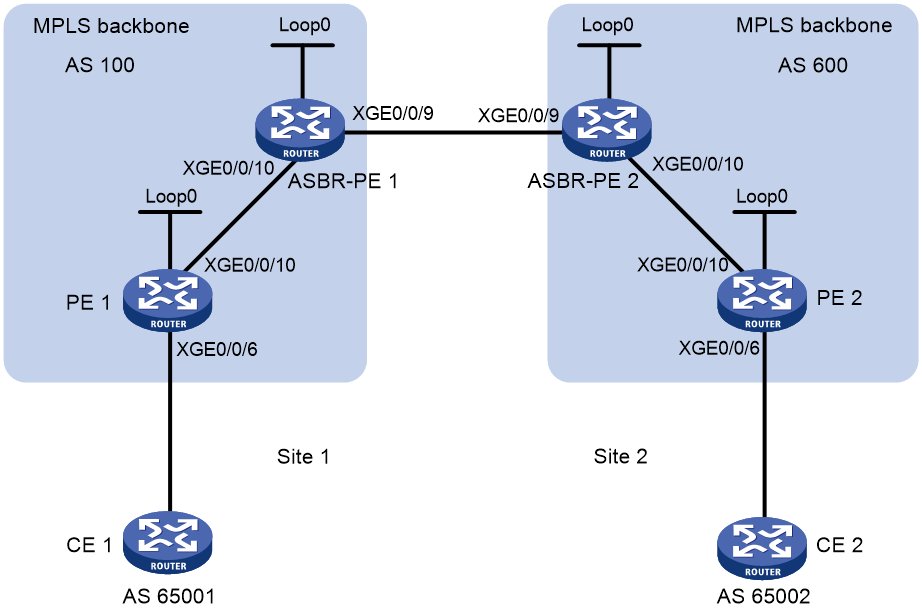
Table 5 Interface and IP address assignment
|
Device |
Interface |
IP address |
Device |
Interface |
IP address |
|
PE 1 |
Loop0 |
2.2.2.9/32 |
PE 2 |
Loop0 |
5.5.5.9/32 |
|
|
XGE0/0/6 |
30::1/64 |
|
XGE0/0/6 |
20::1/64 |
|
|
XGE0/0/10 |
1.1.1.2/8 |
|
XGE0/0/10 |
9.1.1.2/8 |
|
ASBR-PE 1 |
Loop0 |
3.3.3.9/32 |
ASBR-PE 2 |
Loop0 |
4.4.4.9/32 |
|
|
XGE0/0/10 |
1.1.1.1/8 |
|
XGE0/0/10 |
9.1.1.1/8 |
|
|
XGE0/0/9 |
11.0.0.2/8 |
|
XGE0/0/9 |
11.0.0.1/8 |
Procedure
1. Configure PE 1:
# Configure IS-IS on PE 1.
<PE1> system-view
[PE1] isis 1
[PE1-isis-1] network-entity 10.0000.0000.0000.0001.00
[PE1-isis-1] quit
# Configure LSR ID, and enable MPLS and LDP.
[PE1] mpls lsr-id 2.2.2.9
[PE1] mpls ldp
[PE1-ldp] quit
# Configure interface Ten-GigabitEthernet 0/0/10, and enable IS-IS, MPLS, and LDP on the interface.
[PE1] interface ten-gigabitethernet 0/0/10
[PE1-Ten-GigabitEthernet0/0/10] ip address 1.1.1.2 255.0.0.0
[PE1-Ten-GigabitEthernet0/0/10] isis enable 1
[PE1-Ten-GigabitEthernet0/0/10] mpls enable
[PE1-Ten-GigabitEthernet0/0/10] mpls ldp enable
[PE1-Ten-GigabitEthernet0/0/10] quit
# Configure interface Loopback 0, and enable IS-IS on it.
[PE1] interface loopback 0
[PE1-LoopBack0] ip address 2.2.2.9 32
[PE1-LoopBack0] isis enable 1
[PE1-LoopBack0] quit
# Create VPN instance vpn1, and configure the RD and route target attributes.
[PE1] ip vpn-instance vpn1
[PE1-vpn-instance-vpn1] route-distinguisher 11:11
[PE1-vpn-instance-vpn1] vpn-target 1:1 2:2 import-extcommunity
[PE1-vpn-instance-vpn1] vpn-target 1:1 export-extcommunity
[PE1-vpn-instance-vpn1] quit
# Bind the interface connected to CE 1 to the created VPN instance.
[PE1] interface ten-gigabitethernet 0/0/6
[PE1-Ten-GigabitEthernet0/0/6] ip binding vpn-instance vpn1
[PE1-Ten-GigabitEthernet0/0/6] ip address 30::1 64
[PE1-Ten-GigabitEthernet0/0/6] quit
# Enable BGP on PE 1.
[PE1] bgp 100
# Configure IBGP peer 3.3.3.9 as a VPNv6 peer.
[PE1-bgp-default] peer 3.3.3.9 as-number 100
[PE1-bgp-default] peer 3.3.3.9 connect-interface loopback 0
[PE1-bgp-default] address-family vpnv6
[PE1-bgp-default-vpnv6] peer 3.3.3.9 enable
[PE1-bgp-default-vpnv6] quit
# Redistribute direct routes to the VPN routing table of vpn1.
[PE1-bgp-default] ip vpn-instance vpn1
[PE1-bgp-default-vpn1] address-family ipv6 unicast
[PE1-bgp-default-ipv6-vpn1] import-route direct
[PE1-bgp-default-ipv6-vpn1] quit
[PE1-bgp-default-vpn1] quit
[PE1-bgp-default] quit
2. Configure ASBR-PE 1:
# Enable IS-IS on ASBR-PE 1.
<ASBR-PE1> system-view
[ASBR-PE1] isis 1
[ASBR-PE1-isis-1] network-entity 10.0000.0000.0000.0002.00
[ASBR-PE1-isis-1] quit
# Configure LSR ID, and enable MPLS and LDP.
[ASBR-PE1] mpls lsr-id 3.3.3.9
[ASBR-PE1] mpls ldp
[ASBR-PE1-ldp] quit
# Configure interface Ten-GigabitEthernet 0/0/10, and enable IS-IS, MPLS, and LDP on the interface.
[ASBR-PE1] interface ten-gigabitethernet 0/0/10
[ASBR-PE1-Ten-GigabitEthernet0/0/10] ip address 1.1.1.1 255.0.0.0
[ASBR-PE1-Ten-GigabitEthernet0/0/10] isis enable 1
[ASBR-PE1-Ten-GigabitEthernet0/0/10] mpls enable
[ASBR-PE1-Ten-GigabitEthernet0/0/10] mpls ldp enable
[ASBR-PE1-Ten-GigabitEthernet0/0/10] quit
# Configure interface Ten-GigabitEthernet 0/0/9, and enable MPLS.
[ASBR-PE1] interface ten-gigabitethernet 0/0/9
[ASBR-PE1-Ten-GigabitEthernet0/0/9] ip address 11.0.0.2 255.0.0.0
[ASBR-PE1-Ten-GigabitEthernet0/0/9] mpls enable
[ASBR-PE1-Ten-GigabitEthernet0/0/9] quit
# Configure interface Loopback 0, and enable IS-IS on it.
[ASBR-PE1] interface loopback 0
[ASBR-PE1-LoopBack0] ip address 3.3.3.9 32
[ASBR-PE1-LoopBack0] isis enable 1
[ASBR-PE1-LoopBack0] quit
# Enable BGP on ASBR-PE 1.
[ASBR-PE1] bgp 100
[ASBR-PE1-bgp-default] peer 2.2.2.9 as-number 100
[ASBR-PE1-bgp-default] peer 2.2.2.9 connect-interface loopback 0
[ASBR-PE1-bgp-default] peer 11.0.0.1 as-number 600
[ASBR-PE1-bgp-default] peer 11.0.0.1 connect-interface ten-gigabitethernet 0/0/9
# Disable route target based filtering of received VPNv6 routes.
[ASBR-PE1-bgp-default] address-family vpnv6
[ASBR-PE1-bgp-default-vpnv6] undo policy vpn-target
# Configure IBGP peer 2.2.2.9 and EBGP peer 11.0.0.1 as VPNv6 peers.
[ASBR-PE1-bgp-default-vpnv6] peer 11.0.0.1 enable
[ASBR-PE1-bgp-default-vpnv6] peer 2.2.2.9 enable
[ASBR-PE1-bgp-default-vpnv6] quit
3. Configure ASBR-PE 2:
# Enable IS-IS on ASBR-PE 2.
<ASBR-PE2> system-view
[ASBR-PE2] isis 1
[ASBR-PE2-isis-1] network-entity 10.0000.0000.0000.0003.00
[ASBR-PE2-isis-1] quit
# Configure LSR ID, and enable MPLS and LDP.
[ASBR-PE2] mpls lsr-id 4.4.4.9
[ASBR-PE2] mpls ldp
[ASBR-PE2-ldp] quit
# Configure interface Ten-GigabitEthernet 0/0/10, and enable IS-IS, MPLS, and LDP on the interface.
[ASBR-PE2] interface ten-gigabitethernet 0/0/10
[ASBR-PE2-Ten-GigabitEthernet0/0/10] ip address 9.1.1.1 255.0.0.0
[ASBR-PE2-Ten-GigabitEthernet0/0/10] isis enable 1
[ASBR-PE2-Ten-GigabitEthernet0/0/10] mpls enable
[ASBR-PE2-Ten-GigabitEthernet0/0/10] mpls ldp enable
[ASBR-PE2-Ten-GigabitEthernet0/0/10] quit
# Configure interface Ten-GigabitEthernet 0/0/9, and enable MPLS.
[ASBR-PE2] interface ten-gigabitethernet 0/0/9
[ASBR-PE2-Ten-GigabitEthernet0/0/9] ip address 11.0.0.1 255.0.0.0
[ASBR-PE2-Ten-GigabitEthernet0/0/9] mpls enable
[ASBR-PE2-Ten-GigabitEthernet0/0/9] quit
# Configure interface Loopback 0, and enable IS-IS on it.
[ASBR-PE2] interface loopback 0
[ASBR-PE2-LoopBack0] ip address 4.4.4.9 32
[ASBR-PE2-LoopBack0] isis enable 1
[ASBR-PE2-LoopBack0] quit
# Enable BGP on ASBR-PE 2.
[ASBR-PE2] bgp 600
[ASBR-PE2-bgp-default] peer 11.0.0.2 as-number 100
[ASBR-PE2-bgp-default] peer 11.0.0.2 connect-interface ten-gigabitethernet 0/0/9
[ASBR-PE2-bgp-default] peer 5.5.5.9 as-number 600
[ASBR-PE2-bgp-default] peer 5.5.5.9 connect-interface loopback 0
# Disable route target based filtering of received VPNv6 routes.
[ASBR-PE2-bgp-default] address-family vpnv6
[ASBR-PE2-bgp-default-vpnv6] undo policy vpn-target
# Configure IBGP peer 5.5.5.9 and EBGP peer 11.0.0.2 as VPNv6 peers.
[ASBR-PE2-bgp-default-vpnv6] peer 11.0.0.2 enable
[ASBR-PE2-bgp-default-vpnv6] peer 5.5.5.9 enable
[ASBR-PE2-bgp-default-vpnv6] quit
[ASBR-PE2-bgp-default] quit
4. Configure PE 2:
# Enable IS-IS on PE 2.
<PE2> system-view
[PE2] isis 1
[PE2-isis-1] network-entity 10.0000.0000.0000.0004.00
[PE2-isis-1] quit
# Configure the LSR ID, and enable MPLS and LDP.
[PE2] mpls lsr-id 5.5.5.9
[PE2] mpls ldp
[PE2-ldp] quit
# Configure interface Ten-GigabitEthernet 0/0/10, and enable IS-IS, MPLS, and LDP on the interface.
[PE2] interface ten-gigabitethernet 0/0/10
[PE2-Ten-GigabitEthernet0/0/10] ip address 9.1.1.2 255.0.0.0
[PE2-Ten-GigabitEthernet0/0/10] isis enable 1
[PE2-Ten-GigabitEthernet0/0/10] mpls enable
[PE2-Ten-GigabitEthernet0/0/10] mpls ldp enable
[PE2-Ten-GigabitEthernet0/0/10] quit
# Configure interface Loopback 0, and enable IS-IS on it.
[PE2] interface loopback 0
[PE2-LoopBack0] ip address 5.5.5.9 32
[PE2-LoopBack0] isis enable 1
[PE2-LoopBack0] quit
# Create VPN instance vpn1, and configure the RD and route target attributes.
[PE2] ip vpn-instance vpn1
[PE2-vpn-instance-vpn1] route-distinguisher 12:12
[PE2-vpn-instance-vpn1] vpn-target 1:1 2:2 import-extcommunity
[PE2-vpn-instance-vpn1] vpn-target 2:2 export-extcommunity
[PE2-vpn-instance-vpn1] quit
# Bind the interface connected to CE 1 to the created VPN instance.
[PE2] interface ten-gigabitethernet 0/0/6
[PE2-Ten-GigabitEthernet0/0/6] ip binding vpn-instance vpn1
[PE2-Ten-GigabitEthernet0/0/6] ipv6 address 20::1 64
[PE2-Ten-GigabitEthernet0/0/6] quit
# Enable BGP on PE 2.
[PE2] bgp 600
# Configure IBGP peer 4.4.4.9 as a VPNv6 peer.
[PE2-bgp-default] peer 4.4.4.9 as-number 600
[PE2-bgp-default] peer 4.4.4.9 connect-interface loopback 0
[PE2-bgp-default] address-family vpnv6
[PE2-bgp-default-vpnv6] peer 4.4.4.9 enable
[PE2-bgp-default-vpnv6] quit
# Redistribute direct routes to the VPN routing table of vpn1.
[PE2-bgp-default] ip vpn-instance vpn1
[PE2-bgp-default-vpn1] address-family ipv6 unicast
[PE2-bgp-default-ipv6-vpn1] import-route direct
[PE2-bgp-default-ipv6-vpn1] quit
[PE2-bgp-default-vpn1] quit
[PE2-bgp-default] quit
Verifying the configuration
# Use the following command on PE 1 to verify its connectivity to PE 2.
[PE1] ping ipv6 -a 30::1 -vpn-instance vpn1 20::1
Ping6(56 data bytes) 30::1-->20::1, press CTRL_C to break
56 bytes from 20::1: icmp_seq=0 hlim=64 time=1.208 ms
56 bytes from 20::1: icmp_seq=1 hlim=64 time=0.867 ms
56 bytes from 20::1: icmp_seq=2 hlim=64 time=0.551 ms
56 bytes from 20::1: icmp_seq=3 hlim=64 time=0.566 ms
56 bytes from 20::1: icmp_seq=4 hlim=64 time=0.570 ms
--- Ping6 statistics for 20::1 in VPN instance vpn1---
5 packet(s) transmitted, 5 packet(s) received, 0.0% packet loss
round-trip min/avg/max/std-dev = 0.551/0.752/1.208/0.257 ms
Example: Configuring IPv6 MPLS L3VPN inter-AS option C
Network configuration
Site 1 and Site 2 belong to the same VPN. Site 1 accesses the network through PE 1 in AS 100. Site 2 accesses the network through PE 2 in AS 600. PEs in the same AS run IS-IS.
PE 1 and ASBR-PE 1 exchange labeled IPv4 routes by IBGP. PE 2 and ASBR-PE 2 exchange labeled IPv4 routes by IBGP. PE 1 and PE 2 are MP-EBGP peers to exchange VPNv6 routes.
ASBR-PE 1 and ASBR-PE 2 use their respective routing policies and label the routes received from each other.
ASBR-PE 1 and ASBR-PE 2 use EBGP to exchange labeled IPv4 routes.
Figure 8 Network diagram
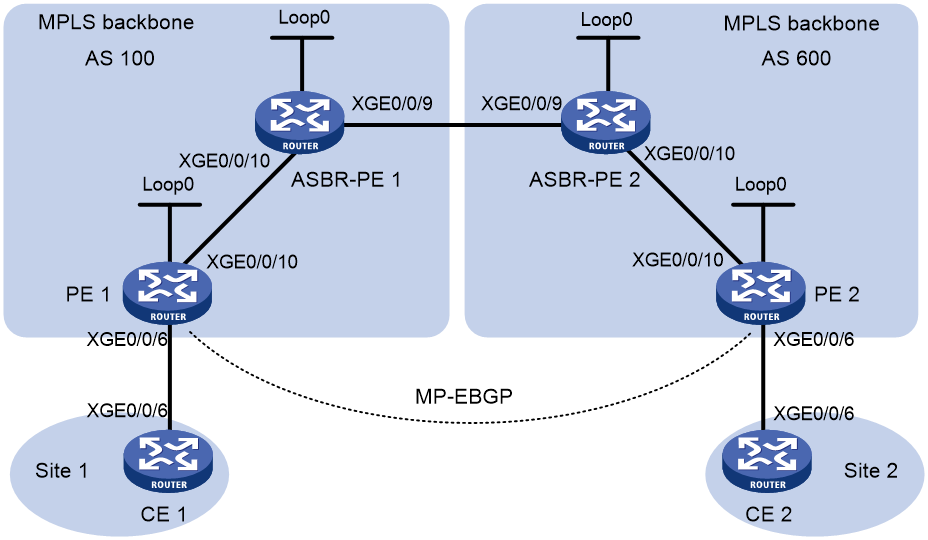
Table 6 Interface and IP address assignment
|
Device |
Interface |
IP address |
Device |
Interface |
IP address |
|
PE 1 |
Loop0 |
2.2.2.9/32 |
PE 2 |
Loop0 |
5.5.5.9/32 |
|
|
XGE0/0/6 |
2001::1/64 |
|
XGE0/0/6 |
2002::1/64 |
|
|
XGE0/0/10 |
1.1.1.2/8 |
|
XGE0/0/10 |
9.1.1.2/8 |
|
ASBR-PE 1 |
Loop0 |
3.3.3.9/32 |
ASBR-PE 2 |
Loop0 |
4.4.4.9/32 |
|
|
XGE0/0/10 |
1.1.1.1/8 |
|
XGE0/0/10 |
9.1.1.1/8 |
|
|
XGE0/0/9 |
11.0.0.2/8 |
|
XGE0/0/9 |
11.0.0.1/8 |
|
CE 1 |
XGE0/0/6 |
2001::2/64 |
CE 1 |
XGE0/0/6 |
2002::2/64 |
Procedure
1. Configure CE 1:
# Configure an IPv6 address for Ten-GigabitEthernet 0/0/6.
<CE1> system-view
[CE1] interface ten-gigabitethernet 0/0/6
[CE1-Ten-GigabitEthernet0/0/6] ipv6 address 2001::2 64
[CE1-Ten-GigabitEthernet0/0/6] quit
# Establish an EBGP peer relationship with PE 1, and redistribute VPN routes.
[CE1] bgp 65001
[CE1-bgp-default] peer 2001::1 as-number 100
[CE1-bgp-default] address-family ipv6 unicast
[CE1-bgp-default-ipv6] peer 2001::1 enable
[CE1-bgp-default-ipv6] import-route direct
[CE1-bgp-default-ipv6] quit
[CE1-bgp-default] quit
2. Configure PE 1:
# Configure IS-IS on PE 1.
<PE1> system-view
[PE1] isis 1
[PE1-isis-1] network-entity 10.0000.0000.0000.0001.00
[PE1-isis-1] quit
# Configure an LSR ID, and enable MPLS and LDP.
[PE1] mpls lsr-id 2.2.2.9
[PE1] mpls ldp
[PE1-ldp] quit
# Configure Ten-GigabitEthernet 0/0/10, and enable IS-IS, MPLS, and LDP on the interface.
[PE1] interface ten-gigabitethernet 0/0/10
[PE1-Ten-GigabitEthernet0/0/10] ip address 1.1.1.2 255.0.0.0
[PE1-Ten-GigabitEthernet0/0/10] isis enable 1
[PE1-Ten-GigabitEthernet0/0/10] mpls enable
[PE1-Ten-GigabitEthernet0/0/10] mpls ldp enable
[PE1-Ten-GigabitEthernet0/0/10] quit
# Configure Loopback 0 and start IS-IS on it.
[PE1] interface loopback 0
[PE1-LoopBack0] ip address 2.2.2.9 32
[PE1-LoopBack0] isis enable 1
[PE1-LoopBack0] quit
# Create VPN instance vpn1, and configure the RD and route target attributes for it.
[PE1] ip vpn-instance vpn1
[PE1-vpn-instance-vpn1] route-distinguisher 11:11
[PE1-vpn-instance-vpn1] vpn-target 3:3 import-extcommunity
[PE1-vpn-instance-vpn1] vpn-target 3:3 export-extcommunity
[PE1-vpn-instance-vpn1] quit
# Associate Ten-GigabitEthernet 0/0/6 with VPN instance vpn1, and specify the IPv6 address for the interface.
[PE1] interface ten-gigabitethernet 0/0/6
[PE1-Ten-GigabitEthernet0/0/6] ip binding vpn-instance vpn1
[PE1-Ten-GigabitEthernet0/0/6] ipv6 address 2001::1 64
[PE1-Ten-GigabitEthernet0/0/6] quit
# Start BGP on PE 1.
[PE1] bgp 100
# Enable the capability to advertise labeled routes to and receive labeled routes from IBGP peer 3.3.3.9.
[PE1-bgp-default] peer 3.3.3.9 as-number 100
[PE1-bgp-default] peer 3.3.3.9 connect-interface loopback 0
[PE1-bgp-default] address-family ipv4 unicast
[PE1-bgp-default-ipv4] peer 3.3.3.9 enable
[PE1-bgp-default-ipv4] peer 3.3.3.9 label-route-capability
[PE1-bgp-default-ipv4] quit
# Configure the maximum hop count from PE 1 to EBGP peer 5.5.5.9 as 10.
[PE1-bgp-default] peer 5.5.5.9 as-number 600
[PE1-bgp-default] peer 5.5.5.9 connect-interface loopback 0
[PE1-bgp-default] peer 5.5.5.9 ebgp-max-hop 10
# Configure peer 5.5.5.9 as a VPNv6 peer.
[PE1-bgp-default] address-family vpnv6
[PE1-bgp-default-af-vpnv6] peer 5.5.5.9 enable
[PE1-bgp-default-af-vpnv6] quit
# Establish an EBGP peer relationship with CE 1, and add the learned BGP routes to the routing table of VPN instance vpn1.
[PE1-bgp-default] ip vpn-instance vpn1
[PE1-bgp-default-vpn1] peer 2001::2 as-number 65001
[PE1-bgp-default-vpn1] address-family ipv6 unicast
[PE1-bgp-default-ipv6-vpn1] peer 2001::2 enable
[PE1-bgp-default-ipv6-vpn1] quit
[PE1-bgp-default-vpn1] quit
[PE1-bgp-default] quit
3. Configure ASBR-PE 1:
# Start IS-IS on ASBR-PE 1.
<ASBR-PE1> system-view
[ASBR-PE1] isis 1
[ASBR-PE1-isis-1] network-entity 10.0000.0000.0000.0002.00
[ASBR-PE1-isis-1] quit
# Configure an LSR ID, and enable MPLS and LDP.
[ASBR-PE1] mpls lsr-id 3.3.3.9
[ASBR-PE1] mpls ldp
[ASBR-PE1-ldp] quit
# Configure Ten-GigabitEthernet 0/0/10, and enable IS-IS, MPLS, and LDP on the interface.
[ASBR-PE1] interface ten-gigabitethernet 0/0/10
[ASBR-PE1-Ten-GigabitEthernet0/0/10] ip address 1.1.1.1 255.0.0.0
[ASBR-PE1-Ten-GigabitEthernet0/0/10] isis enable 1
[ASBR-PE1-Ten-GigabitEthernet0/0/10] mpls enable
[ASBR-PE1-Ten-GigabitEthernet0/0/10] mpls ldp enable
[ASBR-PE1-Ten-GigabitEthernet0/0/10] quit
# Configure Ten-GigabitEthernet 0/0/9, and enable MPLS on it.
[ASBR-PE1] interface ten-gigabitethernet 0/0/9
[ASBR-PE1-Ten-GigabitEthernet0/0/9] ip address 11.0.0.2 255.0.0.0
[ASBR-PE1-Ten-GigabitEthernet0/0/9] mpls enable
[ASBR-PE1-Ten-GigabitEthernet0/0/9] quit
# Configure Loopback 0, and start IS-IS on it.
[ASBR-PE1] interface loopback 0
[ASBR-PE1-LoopBack0] ip address 3.3.3.9 32
[ASBR-PE1-LoopBack0] isis enable 1
[ASBR-PE1-LoopBack0] quit
# Create routing policies.
[ASBR-PE1] route-policy policy1 permit node 1
[ASBR-PE1-route-policy-policy1-1] apply mpls-label
[ASBR-PE1-route-policy-policy1-1] quit
[ASBR-PE1] route-policy policy2 permit node 1
[ASBR-PE1-route-policy-policy2-1] if-match mpls-label
[ASBR-PE1-route-policy-policy2-1] apply mpls-label
[ASBR-PE1-route-policy-policy2-1] quit
# Start BGP on ASBR-PE 1, and apply routing policy policy2 to routes advertised to IBGP peer 2.2.2.9.
[ASBR-PE1] bgp 100
[ASBR-PE1-bgp-default] peer 2.2.2.9 as-number 100
[ASBR-PE1-bgp-default] peer 2.2.2.9 connect-interface loopback 0
[ASBR-PE1-bgp-default] address-family ipv4 unicast
[ASBR-PE1-bgp-default-ipv4] peer 2.2.2.9 enable
[ASBR-PE1-bgp-default-ipv4] peer 2.2.2.9 route-policy policy2 export
# Enable the capability to advertise labeled routes to and receive labeled routes from IBGP peer 2.2.2.9.
[ASBR-PE1-bgp-default-ipv4] peer 2.2.2.9 label-route-capability
# Redistribute routes from IS-IS process 1
[ASBR-PE1-bgp-default-ipv4] import-route isis 1
[ASBR-PE1-bgp-default-ipv4] quit
# Apply routing policy policy1 to routes advertised to EBGP peer 11.0.0.1.
[ASBR-PE1-bgp-default] peer 11.0.0.1 as-number 600
[ASBR-PE1-bgp-default] address-family ipv4 unicast
[ASBR-PE1-bgp-default-ipv4] peer 11.0.0.1 enable
[ASBR-PE1-bgp-default-ipv4] peer 11.0.0.1 route-policy policy1 export
# Enable the capability to advertise labeled routes to and receive labeled routes from EBGP peer 11.0.0.1.
[ASBR-PE1-bgp-default-ipv4] peer 11.0.0.1 label-route-capability
[ASBR-PE1-bgp-default-ipv4] quit
[ASBR-PE1-bgp-default] quit
4. Configure ASBR-PE 2:
# Start IS-IS on ASBR-PE 2.
<ASBR-PE2> system-view
[ASBR-PE2] isis 1
[ASBR-PE2-isis-1] network-entity 10.0000.0000.0000.0003.00
[ASBR-PE2-isis-1] quit
# Configure an LSR ID, and enable MPLS and LDP.
[ASBR-PE2] mpls lsr-id 4.4.4.9
[ASBR-PE2] mpls ldp
[ASBR-PE2-ldp] quit
# Configure Ten-GigabitEthernet 0/0/10, and enable IS-IS, MPLS, and LDP on the interface.
[ASBR-PE2] interface ten-gigabitethernet 0/0/10
[ASBR-PE2-Ten-GigabitEthernet0/0/10] ip address 9.1.1.1 255.0.0.0
[ASBR-PE2-Ten-GigabitEthernet0/0/10] isis enable 1
[ASBR-PE2-Ten-GigabitEthernet0/0/10] mpls enable
[ASBR-PE2-Ten-GigabitEthernet0/0/10] mpls ldp enable
[ASBR-PE2-Ten-GigabitEthernet0/0/10] quit
# Configure Loopback 0, and start IS-IS on it.
[ASBR-PE2] interface loopback 0
[ASBR-PE2-LoopBack0] ip address 4.4.4.9 32
[ASBR-PE2-LoopBack0] isis enable 1
[ASBR-PE2-LoopBack0] quit
# Configure Ten-GigabitEthernet 0/0/9, and enable MPLS on it.
[ASBR-PE2] interface ten-gigabitethernet 0/0/9
[ASBR-PE2-Ten-GigabitEthernet0/0/9] ip address 11.0.0.1 255.0.0.0
[ASBR-PE2-Ten-GigabitEthernet0/0/9] mpls enable
[ASBR-PE2-Ten-GigabitEthernet0/0/9] quit
# Create routing policies.
[ASBR-PE2] route-policy policy1 permit node 1
[ASBR-PE2-route-policy-policy1-1] apply mpls-label
[ASBR-PE2-route-policy-policy1-1] quit
[ASBR-PE2] route-policy policy2 permit node 1
[ASBR-PE2-route-policy-policy2-1] if-match mpls-label
[ASBR-PE2-route-policy-policy2-1] apply mpls-label
[ASBR-PE2-route-policy-policy2-1] quit
# Start BGP on ASBR-PE 2, and enable the capability to advertise labeled routes to and receive labeled routes from IBGP peer 5.5.5.9.
[ASBR-PE2] bgp 600
[ASBR-PE2-bgp-default] peer 5.5.5.9 as-number 600
[ASBR-PE2-bgp-default] peer 5.5.5.9 connect-interface loopback 0
[ASBR-PE2-bgp-default] address-family ipv4 unicast
[ASBR-PE2-bgp-default-ipv4] peer 5.5.5.9 enable
[ASBR-PE2-bgp-default-ipv4] peer 5.5.5.9 label-route-capability
# Apply routing policy policy2 to routes advertised to IBGP peer 5.5.5.9.
[ASBR-PE2-bgp-default-ipv4] peer 5.5.5.9 route-policy policy2 export
# Redistribute routes from IS-IS process 1.
[ASBR-PE2-bgp-default-ipv4] import-route isis 1
[ASBR-PE2-bgp-default-ipv4] quit
# Apply routing policy policy1 to routes advertised to EBGP peer 11.0.0.2.
[ASBR-PE2-bgp-default] peer 11.0.0.2 as-number 100
[ASBR-PE2-bgp-default] address-family ipv4 unicast
[ASBR-PE2-bgp-default-ipv4] peer 11.0.0.2 enable
[ASBR-PE2-bgp-default-ipv4] peer 11.0.0.2 route-policy policy1 export
# Enable the capability to advertise labeled routes to and receive labeled routes from EBGP peer 11.0.0.2.
[ASBR-PE2-bgp-default-ipv4] peer 11.0.0.2 label-route-capability
[ASBR-PE2-bgp-default-ipv4] quit
[ASBR-PE2-bgp-default] quit
5. Configure PE 2:
# Start IS-IS on PE 2.
<PE2> system-view
[PE2] isis 1
[PE2-isis-1] network-entity 10.0000.0000.0000.0004.00
[PE2-isis-1] quit
# Configure an LSR ID, and enable MPLS and LDP.
[PE2] mpls lsr-id 5.5.5.9
[PE2] mpls ldp
[PE2-ldp] quit
# Configure Ten-GigabitEthernet 0/0/10, and enable IS-IS, MPLS, and LDP on the interface.
[PE2] interface ten-gigabitethernet 0/0/10
[PE2-Ten-GigabitEthernet0/0/10] ip address 9.1.1.2 255.0.0.0
[PE2-Ten-GigabitEthernet0/0/10] isis enable 1
[PE2-Ten-GigabitEthernet0/0/10] mpls enable
[PE2-Ten-GigabitEthernet0/0/10] mpls ldp enable
[PE2-Ten-GigabitEthernet0/0/10] quit
# Configure Loopback 0, and start IS-IS on it.
[PE2] interface loopback 0
[PE2-LoopBack0] ip address 5.5.5.9 32
[PE2-LoopBack0] isis enable 1
[PE2-LoopBack0] quit
# Create VPN instance vpn1, and configure the RD and route target attributes for it.
[PE2] ip vpn-instance vpn1
[PE2-vpn-instance-vpn1] route-distinguisher 11:11
[PE2-vpn-instance-vpn1] vpn-target 3:3 import-extcommunity
[PE2-vpn-instance-vpn1] vpn-target 3:3 export-extcommunity
[PE2-vpn-instance-vpn1] quit
# Associate Ten-GigabitEthernet 0/0/6 with VPN instance vpn1, and specify the IPv6 address for the interface.
[PE2] interface ten-gigabitethernet 0/0/6
[PE2-Ten-GigabitEthernet0/0/6] ip binding vpn-instance vpn1
[PE2-Ten-GigabitEthernet0/0/6] ipv6 address 2002::1 64
[PE2-Ten-GigabitEthernet0/0/6] quit
# Start BGP.
[PE2] bgp 600
# Enable the capability to advertise labeled routes to and receive labeled routes from IBGP peer 4.4.4.9.
[PE2-bgp-default] peer 4.4.4.9 as-number 600
[PE2-bgp-default] peer 4.4.4.9 connect-interface loopback 0
[PE2-bgp-default] address-family ipv4 unicast
[PE2-bgp-default-ipv4] peer 4.4.4.9 enable
[PE2-bgp-default-ipv4] peer 4.4.4.9 label-route-capability
[PE2-bgp-default-ipv4] quit
# Configure the maximum hop count from PE 2 to EBGP peer 2.2.2.9 as 10.
[PE2-bgp-default] peer 2.2.2.9 as-number 100
[PE2-bgp-default] peer 2.2.2.9 connect-interface loopback 0
[PE2-bgp-default] peer 2.2.2.9 ebgp-max-hop 10
# Configure peer 2.2.2.9 as a VPNv6 peer.
[PE2-bgp-default] address-family vpnv6
[PE2-bgp-default-af-vpnv6] peer 2.2.2.9 enable
[PE2-bgp-default-af-vpnv6] quit
# Establish an EBGP peer relationship with CE 2, and add the learned BGP routes to the routing table of VPN instance vpn1.
[PE2-bgp-default] ip vpn-instance vpn1
[PE2-bgp-default-vpn1] peer 2002::2 as-number 65002
[PE2-bgp-default-vpn1] address-family ipv6 unicast
[PE2-bgp-default-ipv6-vpn1] peer 2002::2 enable
[PE2-bgp-default-ipv6-vpn1] quit
[PE2-bgp-default-vpn1] quit
[PE2-bgp-default] quit
6. Configure CE 2:
# Configure an IPv6 address for Ten-GigabitEthernet 0/0/6.
<CE2> system-view
[CE2] interface ten-gigabitethernet 0/0/6
[CE2-Ten-GigabitEthernet0/0/6] ipv6 address 2002::2 64
[CE2-Ten-GigabitEthernet0/0/6] quit
# Establish an EBGP peer relationship with PE 2, and redistribute VPN routes.
[CE2] bgp 65002
[CE2-bgp-default] peer 2002::1 as-number 600
[CE2-bgp-default] address-family ipv6 unicast
[CE2-bgp-default-ipv6] peer 2002::1 enable
[CE2-bgp-default-ipv6] import-route direct
[CE2-bgp-default-ipv6] quit
[CE2-bgp-default] quit
Verifying the configuration
# Execute the display ipv6 routing table command on CE 1 and CE 2 to verify that CE 1 and CE 2 have a route to each other. Verify that CE 1 and CE 2 can ping each other. (Details not shown.)
Example: Configuring IPv6 MPLS L3VPN carrier's carrier in the same AS
Network configuration
Configure carrier's carrier for the scenario shown in Figure 9. In this scenario:
· PE 1 and PE 2 are the provider carrier's PE routers. They provide VPN services to the customer carrier.
· CE 1 and CE 2 are the customer carrier's routers. They are connected to the provider carrier's backbone as CE routers.
· PE 3 and PE 4 are the customer carrier's PE routers. They provide IPv6 MPLS L3VPN services to end customers.
· CE 3 and CE 4 are customers of the customer carrier.
· The customer carrier and the provider carrier reside in the same AS.
The key to the carrier's carrier deployment is to configure exchange of two kinds of routes:
· Exchange of the customer carrier's internal routes on the provider carrier's backbone.
· Exchange of the end customers' internal routes between PE 3 and PE 4, the PEs of the customer carrier. In this process, an MP-IBGP peer relationship must be established between PE 3 and PE 4.
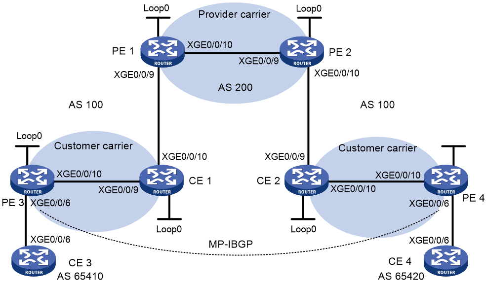
Table 7 Interface and IP address assignment
|
Device |
Interface |
IP address |
Device |
Interface |
IP address |
|
CE 3 |
XGE0/0/6 |
2001:1::1/96 |
CE 4 |
XGE0/0/6 |
2001:2::1/96 |
|
PE 3 |
Loop0 |
1.1.1.9/32 |
PE 4 |
Loop0 |
6.6.6.9/32 |
|
|
XGE0/0/6 |
2001:1::2/96 |
|
XGE0/0/6 |
2001:2::2/96 |
|
|
XGE0/0/10 |
10.1.1.1/24 |
|
XGE0/0/10 |
20.1.1.2/24 |
|
CE 1 |
Loop0 |
2.2.2.9/32 |
CE 2 |
Loop0 |
5.5.5.9/32 |
|
|
XGE0/0/9 |
10.1.1.2/24 |
|
XGE0/0/9 |
21.1.1.2/24 |
|
|
XGE0/0/10 |
11.1.1.1/24 |
|
XGE0/0/10 |
20.1.1.1/24 |
|
PE 1 |
Loop0 |
3.3.3.9/32 |
PE 2 |
Loop0 |
4.4.4.9/32 |
|
|
XGE0/0/9 |
11.1.1.2/24 |
|
XGE0/0/9 |
30.1.1.2/24 |
|
|
XGE0/0/10 |
30.1.1.1/24 |
|
XGE0/0/10 |
21.1.1.1/24 |
Procedure
1. Configure MPLS L3VPN on the provider carrier backbone. Start IS-IS as the IGP, enable LDP on PE 1 and PE 2, and establish an MP-IBGP peer relationship between the PEs:
# Configure PE 1.
<PE1> system-view
[PE1] interface loopback 0
[PE1-LoopBack0] ip address 3.3.3.9 32
[PE1-LoopBack0] quit
[PE1] mpls lsr-id 3.3.3.9
[PE1] mpls ldp
[PE1-ldp] quit
[PE1] isis 1
[PE1-isis-1] network-entity 10.0000.0000.0000.0004.00
[PE1-isis-1] quit
[PE1] interface loopback 0
[PE1-LoopBack0] isis enable 1
[PE1-LoopBack0] quit
[PE1] interface ten-gigabitethernet 0/0/10
[PE1-Ten-GigabitEthernet0/0/10] ip address 30.1.1.1 24
[PE1-Ten-GigabitEthernet0/0/10] isis enable 1
[PE1-Ten-GigabitEthernet0/0/10] mpls enable
[PE1-Ten-GigabitEthernet0/0/10] mpls ldp enable
[PE1-Ten-GigabitEthernet0/0/10] mpls ldp transport-address interface
[PE1-Ten-GigabitEthernet0/0/10] quit
[PE1] bgp 100
[PE1-bgp-default] peer 4.4.4.9 as-number 100
[PE1-bgp-default] peer 4.4.4.9 connect-interface loopback 0
[PE1-bgp-default] address-family vpnv4
[PE1-bgp-default-vpnv4] peer 4.4.4.9 enable
[PE1-bgp-default-vpnv4] quit
[PE1-bgp-default] quit
# Configure PE 2 in the same way that PE 1 is configured. (Details not shown.)
# On PE 1 or PE 2, execute the following commands:
¡ Execute the display mpls ldp peer command to verify that an LDP session in Operational state has been established between PE 1 and PE 2. (Details not shown.)
¡ Execute the display bgp peer vpnv4 command to verify that a BGP peer relationship in Established state has been established between PE 1 and PE 2. (Details not shown.)
¡ Execute the display isis peer command to verify that the IS-IS neighbor relationship has been established between PE 1 and PE 2. (Details not shown.)
2. Configure the customer carrier network. Start IS-IS as the IGP, and enable LDP between PE 3 and CE 1, and between PE 4 and CE 2:
# Configure PE 3.
<PE3> system-view
[PE3] interface loopback 0
[PE3-LoopBack0] ip address 1.1.1.9 32
[PE3-LoopBack0] quit
[PE3] mpls lsr-id 1.1.1.9
[PE3] mpls ldp
[PE3-ldp] quit
[PE3] isis 2
[PE3-isis-2] network-entity 10.0000.0000.0000.0001.00
[PE3-isis-2] quit
[PE3] interface loopback 0
[PE3-LoopBack0] isis enable 2
[PE3-LoopBack0] quit
[PE3] interface ten-gigabitethernet 0/0/10
[PE3-Ten-GigabitEthernet0/0/10] ip address 10.1.1.1 24
[PE3-Ten-GigabitEthernet0/0/10] isis enable 2
[PE3-Ten-GigabitEthernet0/0/10] mpls enable
[PE3-Ten-GigabitEthernet0/0/10] mpls ldp enable
[PE3-Ten-GigabitEthernet0/0/10] mpls ldp transport-address interface
[PE3-Ten-GigabitEthernet0/0/10] quit
# Configure CE 1.
<CE1> system-view
[CE1] interface loopback 0
[CE1-LoopBack0] ip address 2.2.2.9 32
[CE1-LoopBack0] quit
[CE1] mpls lsr-id 2.2.2.9
[CE1] mpls ldp
[CE1-ldp] quit
[CE1] isis 2
[CE1-isis-2] network-entity 10.0000.0000.0000.0002.00
[CE1-isis-2] quit
[CE1] interface loopback 0
[CE1-LoopBack0] isis enable 2
[CE1-LoopBack0] quit
[CE1] interface ten-gigabitethernet 0/0/9
[CE1-Ten-GigabitEthernet0/0/9] ip address 10.1.1.2 24
[CE1-Ten-GigabitEthernet0/0/9] isis enable 2
[CE1-Ten-GigabitEthernet0/0/9] mpls enable
[CE1-Ten-GigabitEthernet0/0/9] mpls ldp enable
[CE1-Ten-GigabitEthernet0/0/9] mpls ldp transport-address interface
[CE1-Ten-GigabitEthernet0/0/9] quit
PE 3 and CE 1 can establish an LDP session and IS-IS neighbor relationship between them.
# Configure PE 4 and CE 2 in the same way that PE 3 and CE 1 are configured. (Details not shown.)
3. Connect the customer carrier and the provider carrier:
# Configure PE 1.
[PE1] ip vpn-instance vpn1
[PE1-vpn-instance-vpn1] route-distinguisher 200:1
[PE1-vpn-instance-vpn1] vpn-target 1:1
[PE1-vpn-instance-vpn1] quit
[PE1] mpls ldp
[PE1-ldp] vpn-instance vpn1
[PE1-ldp-vpn-instance-vpn1] quit
[PE1-ldp] quit
[PE1] isis 2 vpn-instance vpn1
[PE1-isis-2] network-entity 10.0000.0000.0000.0003.00
[PE1-isis-2] address-family ipv4
[PE1-isis-2-ipv4] import-route bgp allow-ibgp
[PE1-isis-2-ipv4] quit
[PE1-isis-2] quit
[PE1] interface ten-gigabitethernet 0/0/9
[PE1-Ten-GigabitEthernet0/0/9] ip binding vpn-instance vpn1
[PE1-Ten-GigabitEthernet0/0/9] ip address 11.1.1.2 24
[PE1-Ten-GigabitEthernet0/0/9] isis enable 2
[PE1-Ten-GigabitEthernet0/0/9] mpls enable
[PE1-Ten-GigabitEthernet0/0/9] mpls ldp enable
[PE1-Ten-GigabitEthernet0/0/9] mpls ldp transport-address interface
[PE1-Ten-GigabitEthernet0/0/9] quit
[PE1] bgp 100
[PE1-bgp-default] ip vpn-instance vpn1
[PE1-bgp-default-vpn1] address-family ipv4 unicast
[PE1-bgp-default-ipv4-vpn1] import-route isis 2
[PE1-bgp-default-ipv4-vpn1] quit
[PE1-bgp-default-vpn1] quit
[PE1-bgp-default] quit
# Configure CE 1.
[CE1] interface ten-gigabitethernet 0/0/10
[CE1-Ten-GigabitEthernet0/0/10] ip address 11.1.1.1 24
[CE1-Ten-GigabitEthernet0/0/10] isis enable 2
[CE1-Ten-GigabitEthernet0/0/10] mpls enable
[CE1-Ten-GigabitEthernet0/0/10] mpls ldp enable
[CE1-Ten-GigabitEthernet0/0/10] mpls ldp transport-address interface
[CE1-Ten-GigabitEthernet0/0/10] quit
PE 1 and CE 1 can establish an LDP session and IS-IS neighbor relationship between them.
# Configure PE 2 and CE 2 in the same way that PE 1 and CE 1 are configured. (Details not shown.)
4. Connect end customers and the customer carrier:
# Configure CE 3.
<CE3> system-view
[CE3] interface ten-gigabitethernet 0/0/6
[CE3-Ten-GigabitEthernet0/0/6] ipv6 address 2001:1::1 96
[CE3-Ten-GigabitEthernet0/0/6] quit
[CE3] bgp 65410
[CE3-bgp-default] peer 2001:1::2 as-number 100
[CE3-bgp-default] address-family ipv6
[CE3-bgp-default-ipv6] peer 2001:1::2 enable
[CE3-bgp-default-ipv6] import-route direct
[CE3-bgp-default-ipv6] quit
[CE3-bgp-default] quit
# Configure PE 3.
[PE3] ip vpn-instance vpn1
[PE3-vpn-instance-vpn1] route-distinguisher 100:1
[PE3-vpn-instance-vpn1] vpn-target 1:1
[PE3-vpn-instance-vpn1] quit
[PE3] interface ten-gigabitethernet 0/0/6
[PE3-Ten-GigabitEthernet0/0/6] ip binding vpn-instance vpn1
[PE3-Ten-GigabitEthernet0/0/6] ipv6 address 2001:1::2 96
[PE3-Ten-GigabitEthernet0/0/6] quit
[PE3] bgp 100
[PE3-bgp-default] ip vpn-instance vpn1
[PE3-bgp-default-vpn1] peer 2001:1::1 as-number 65410
[PE3-bgp-default-vpn1] address-family ipv6 unicast
[PE3-bgp-default-ipv6-vpn1] peer 2001:1::1 enable
[PE3-bgp-default-ipv6-vpn1] quit
[PE3-bgp-default-vpn1] quit
[PE3-bgp-default] quit
# Configure PE 4 and CE 4 in the same way that PE 3 and CE 3 are configured. (Details not shown.)
5. Configure an MP-IBGP peer relationship between the PEs of the customer carrier to exchange the VPN routes of the end customers:
# Configure PE 3.
[PE3] bgp 100
[PE3-bgp-default] peer 6.6.6.9 as-number 100
[PE3-bgp-default] peer 6.6.6.9 connect-interface loopback 0
[PE3-bgp-default] address-family vpnv6
[PE3-bgp-default-af-vpnv6] peer 6.6.6.9 enable
[PE3-bgp-default-af-vpnv6] quit
[PE3-bgp-default] quit
# Configure PE 4 in the same way that PE 3 is configured. (Details not shown.)
Verifying the configuration
1. Display the public network routing table and VPN routing table on the provider carrier PEs, for example, on PE 1:
# Verify that the public network routing table contains only routes of the provider carrier network.
[PE1] display ip routing-table
Destinations : 14 Routes : 14
Destination/Mask Proto Pre Cost NextHop Interface
0.0.0.0/32 Direct 0 0 127.0.0.1 InLoop0
3.3.3.9/32 Direct 0 0 127.0.0.1 InLoop0
4.4.4.9/32 IS_L1 15 10 30.1.1.2 XGE0/0/10
30.1.1.0/24 Direct 0 0 30.1.1.1 XGE0/0/10
30.1.1.0/32 Direct 0 0 30.1.1.1 XGE0/0/10
30.1.1.1/32 Direct 0 0 127.0.0.1 InLoop0
30.1.1.255/32 Direct 0 0 30.1.1.1 XGE0/0/10
127.0.0.0/8 Direct 0 0 127.0.0.1 InLoop0
127.0.0.0/32 Direct 0 0 127.0.0.1 InLoop0
127.0.0.1/32 Direct 0 0 127.0.0.1 InLoop0
127.255.255.255/32 Direct 0 0 127.0.0.1 InLoop0
224.0.0.0/4 Direct 0 0 0.0.0.0 NULL0
224.0.0.0/24 Direct 0 0 0.0.0.0 NULL0
255.255.255.255/32 Direct 0 0 127.0.0.1 InLoop0
# Verify that the VPN routing table contains the internal routes of the customer carrier network.
[PE1] display ip routing-table vpn-instance vpn1
Destinations : 18 Routes : 18
Destination/Mask Proto Pre Cost NextHop Interface
0.0.0.0/32 Direct 0 0 127.0.0.1 InLoop0
1.1.1.9/32 IS_L1 15 20 11.1.1.1 XGE0/0/9
2.2.2.9/32 IS_L1 15 10 11.1.1.1 XGE0/0/9
5.5.5.9/32 BGP 255 10 4.4.4.9 XGE0/0/10
6.6.6.9/32 BGP 255 20 4.4.4.9 XGE0/0/10
10.1.1.0/24 IS_L1 15 20 11.1.1.1 XGE0/0/9
11.1.1.0/24 Direct 0 0 11.1.1.2 XGE0/0/9
11.1.1.0/32 Direct 0 0 11.1.1.2 XGE0/0/9
11.1.1.2/32 Direct 0 0 127.0.0.1 InLoop0
11.1.1.255/32 Direct 0 0 11.1.1.2 XGE0/0/9
20.1.1.0/24 BGP 255 20 4.4.4.9 XGE0/0/10
127.0.0.0/8 Direct 0 0 127.0.0.1 InLoop0
127.0.0.0/32 Direct 0 0 127.0.0.1 InLoop0
127.0.0.1/32 Direct 0 0 127.0.0.1 InLoop0
127.255.255.255/32 Direct 0 0 127.0.0.1 InLoop0
224.0.0.0/4 Direct 0 0 0.0.0.0 NULL0
224.0.0.0/24 Direct 0 0 0.0.0.0 NULL0
255.255.255.255/32 Direct 0 0 127.0.0.1 InLoop0
2. Display the routing table on the customer carrier CEs, for example, on CE 1:
# Verify that the routing table contains the internal routes of the customer carrier network.
[CE1] display ip routing-table
Destinations : 21 Routes : 21
Destination/Mask Proto Pre Cost NextHop Interface
0.0.0.0/32 Direct 0 0 127.0.0.1 InLoop0
1.1.1.9/32 IS_L1 15 10 10.1.1.1 XGE0/0/9
2.2.2.9/32 Direct 0 0 127.0.0.1 InLoop0
5.5.5.9/32 IS_L2 15 74 11.1.1.2 XGE0/0/10
6.6.6.9/32 IS_L2 15 74 11.1.1.2 XGE0/0/10
10.1.1.0/24 Direct 0 0 10.1.1.2 XGE0/0/9
10.1.1.0/32 Direct 0 0 10.1.1.2 XGE0/0/9
10.1.1.2/32 Direct 0 0 127.0.0.1 InLoop0
10.1.1.255/32 Direct 0 0 10.1.1.2 XGE0/0/9
11.1.1.0/24 Direct 0 0 11.1.1.1 XGE0/0/10
11.1.1.0/32 Direct 0 0 11.1.1.1 XGE0/0/10
11.1.1.1/32 Direct 0 0 127.0.0.1 InLoop0
11.1.1.255/32 Direct 0 0 11.1.1.1 XGE0/0/10
20.1.1.0/24 IS_L2 15 74 11.1.1.2 XGE0/0/10
127.0.0.0/8 Direct 0 0 127.0.0.1 InLoop0
127.0.0.0/32 Direct 0 0 127.0.0.1 InLoop0
127.0.0.1/32 Direct 0 0 127.0.0.1 InLoop0
127.255.255.255/32 Direct 0 0 127.0.0.1 InLoop0
224.0.0.0/4 Direct 0 0 0.0.0.0 NULL0
224.0.0.0/24 Direct 0 0 0.0.0.0 NULL0
255.255.255.255/32 Direct 0 0 127.0.0.1 InLoop0
3. Display the public network routing table and VPN routing table on the customer carrier PEs, for example, on PE 3:
# Verify that the public network routing table contains the internal routes of the customer carrier network.
[PE3] display ip routing-table
Destinations : 18 Routes : 18
Destination/Mask Proto Pre Cost NextHop Interface
0.0.0.0/32 Direct 0 0 127.0.0.1 InLoop0
1.1.1.9/32 Direct 0 0 127.0.0.1 InLoop0
2.2.2.9/32 IS_L1 15 10 10.1.1.2 XGE0/0/10
5.5.5.9/32 IS_L2 15 84 10.1.1.2 XGE0/0/10
6.6.6.9/32 IS_L2 15 84 10.1.1.2 XGE0/0/10
10.1.1.0/24 Direct 0 0 10.1.1.1 XGE0/0/10
10.1.1.0/32 Direct 0 0 10.1.1.1 XGE0/0/10
10.1.1.1/32 Direct 0 0 127.0.0.1 InLoop0
10.1.1.255/32 Direct 0 0 10.1.1.1 XGE0/0/10
11.1.1.0/24 IS_L1 15 20 10.1.1.2 XGE0/0/10
20.1.1.0/24 IS_L2 15 84 10.1.1.2 XGE0/0/10
127.0.0.0/8 Direct 0 0 127.0.0.1 InLoop0
127.0.0.0/32 Direct 0 0 127.0.0.1 InLoop0
127.0.0.1/32 Direct 0 0 127.0.0.1 InLoop0
127.255.255.255/32 Direct 0 0 127.0.0.1 InLoop0
224.0.0.0/4 Direct 0 0 0.0.0.0 NULL0
224.0.0.0/24 Direct 0 0 0.0.0.0 NULL0
255.255.255.255/32 Direct 0 0 127.0.0.1 InLoop0
# Verify that the VPN routing table has the remote VPN route.
[PE3] display ipv6 routing-table vpn-instance vpn1
Destinations : 6 Routes : 6
Destination: ::1/128 Protocol : Direct
NextHop : ::1 Preference: 0
Interface : InLoop0 Cost : 0
Destination: 2001:1::/96 Protocol : Direct
NextHop : :: Preference: 0
Interface : XGE0/0/6 Cost : 0
Destination: 2001:1::2/128 Protocol : Direct
NextHop : ::1 Preference: 0
Interface : InLoop0 Cost : 0
Destination: 2001:2::/96 Protocol : BGP4+
NextHop : ::FFFF:6.6.6.9 Preference: 255
Interface : XGE0/0/10 Cost : 0
Destination: FE80::/10 Protocol : Direct
NextHop : :: Preference: 0
Interface : InLoop0 Cost : 0
Destination: FF00::/8 Protocol : Direct
NextHop : :: Preference: 0
Interface : NULL0 Cost : 0
4. Verify that PE 3 and PE 4 can ping each other. (Details not shown.)
5. Verify that CE 3 and CE 4 can ping each other. (Details not shown.)
Example: Configuring multirole host
Network configuration
Configure the multirole host feature to allow Host A to access VPN 1 and VPN 2 and Host B to access only VPN 1.
Figure 10 Network diagram
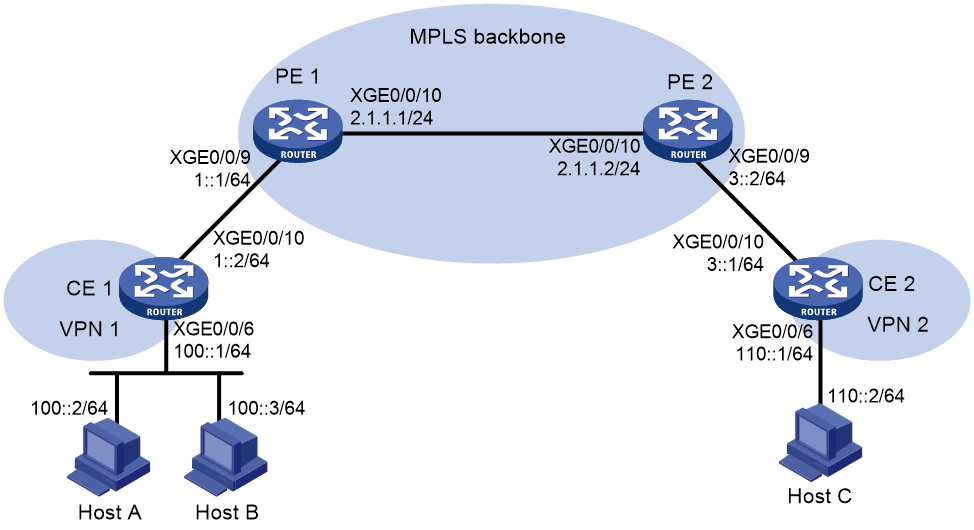
Procedure
1. Configure CE 1:
# Configure IPv6 addresses for interfaces.
<CE1> system-view
[CE1] interface ten-gigabitethernet 0/0/6
[CE1-Ten-GigabitEthernet0/0/6] ipv6 address 100::1 64
[CE1-Ten-GigabitEthernet0/0/6] quit
[CE1] interface ten-gigabitethernet 0/0/10
[CE1-Ten-GigabitEthernet0/0/10] ipv6 address 1::2 64
[CE1-Ten-GigabitEthernet0/0/10] quit
# Configure an IPv6 default route to PE 1.
[CE1] ipv6 route-static :: 0 1::1
2. Configure PE 1:
# Create VPN instances vpn1 and vpn2 for VPN 1 and VPN 2, respectively, and configure different RDs and route targets for the VPN instances.
<PE1> system-view
[PE1] ip vpn-instance vpn1
[PE1-vpn-instance-vpn1] route-distinguisher 100:1
[PE1-vpn-instance-vpn1] vpn-target 100:1 both
[PE1-vpn-instance-vpn1] quit
[PE1] ip vpn-instance vpn2
[PE1-vpn-instance-vpn2] route-distinguisher 100:2
[PE1-vpn-instance-vpn2] vpn-target 100:2 both
[PE1-vpn-instance-vpn2] quit
# Associate VPN instance vpn1 with Ten-GigabitEthernet 0/0/9 (the interface connected to CE 1).
[PE1] interface ten-gigabitethernet 0/0/9
[PE1-Ten-GigabitEthernet0/0/9] ip binding vpn-instance vpn1
[PE1-Ten-GigabitEthernet0/0/9] ipv6 address 1::1 64
[PE1-Ten-GigabitEthernet0/0/9] quit
# Configure an IPv6 static route for VPN 2 to reach Host A and redistribute the route to BGP. This configuration ensures that packets from VPN 2 to Host A can be forwarded through the correct route in the routing table of VPN instance vpn1.
[PE1] ipv6 route-static vpn-instance vpn2 100:: 64 vpn-instance vpn1 1::2
[PE1] bgp 100
[PE1-bgp-default] ip vpn-instance vpn2
[PE1-bgp-default-vpn2] address-family ipv6
[PE1-bgp-default-ipv6-vpn2] import-route static
[PE1-bgp-default-ipv6-vpn2] quit
[PE1-bgp-default-vpn2] quit
[PE1-bgp-default] quit
# Configure PBR to route packets from Host A according to the routing tables of both VPN instances vpn1 and vpn2.
[PE1] acl ipv6 advanced 3001
[PE1-acl-ipv6-adv-3001] rule 0 permit ipv6 vpn-instance vpn1 source 100::2 128
[PE1-acl-ipv6-adv-3001] quit
[PE1] ipv6 policy-based-route policy1 permit node 10
[PE1-policy-based-route] if-match acl 3001
[PE1-policy-based-route] apply access-vpn vpn-instance vpn1 vpn2
[PE1-policy-based-route] quit
# Apply policy policy1 to Ten-GigabitEthernet 0/0/9.
[PE1] interface ten-gigabitethernet 0/0/9
[PE1-Ten-GigabitEthernet0/0/9] ipv6 policy-based-route policy1
3. Configure basic IPv6 MPLS L3VPN. (Details not shown.)
Verifying the configuration
# Verify that Host A can ping Host C, and that Host B cannot ping Host C. (Details not shown.)
Example: Configuring an OSPFv3 sham link
Network configuration
As shown in Figure 11, CE 1 and CE 2 belong to VPN 1. Configure an OSPFv3 sham link between PE 1 and PE 2 so traffic between the CEs is forwarded through the MPLS backbone instead of the backdoor link.
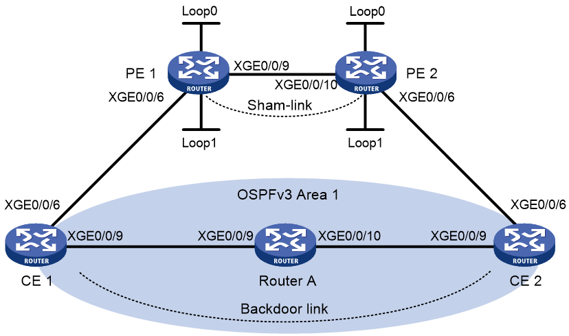
Table 8 Interface and IP address assignment
|
Device |
Interface |
IP address |
Device |
Interface |
IP address |
|
CE 1 |
XGE0/0/6 |
100::1/64 |
CE 2 |
XGE0/0/6 |
120::1/64 |
|
|
XGE0/0/9 |
20::1/64 |
|
XGE0/0/9 |
30::2/64 |
|
PE 1 |
Loop0 |
1.1.1.9/32 |
PE 2 |
Loop0 |
2.2.2.9/32 |
|
|
Loop1 |
3::3/128 |
|
Loop1 |
5::5/128 |
|
|
XGE0/0/6 |
100::2/64 |
|
XGE0/0/6 |
120::2/64 |
|
|
XGE0/0/9 |
10.1.1.1/24 |
|
XGE0/0/10 |
10.1.1.2/24 |
|
Router A |
XGE0/0/10 |
30::1/64 |
|
|
|
|
|
XGE0/0/9 |
20::2/64 |
|
|
|
Procedure
1. Configure OSPFv3 on the customer networks:
# Configure conventional OSPFv3 on CE 1, Router A, and CE 2 to advertise addresses of the interfaces (see Figure 11). (Details not shown.)
# Set the cost value to 2 for both the link between CE 1 and Router A, and the link between CE 2 and Router A. (Details not shown.)
# Execute the display ipv6 routing-table command to verify that CE 1 and CE 2 have learned the route to each other. (Details not shown.)
2. Configure IPv6 MPLS L3VPN on the backbone:
# Configure basic MPLS and MPLS LDP on PE 1 to establish LDP LSPs.
<PE1> system-view
[PE1] interface loopback 0
[PE1-LoopBack0] ip address 1.1.1.9 32
[PE1-LoopBack0] quit
[PE1] mpls lsr-id 1.1.1.9
[PE1] mpls ldp
[PE1-ldp] quit
[PE1] interface ten-gigabitethernet 0/0/9
[PE1-Ten-GigabitEthernet0/0/9] ip address 10.1.1.1 24
[PE1-Ten-GigabitEthernet0/0/9] mpls enable
[PE1-Ten-GigabitEthernet0/0/9] mpls ldp enable
[PE1-Ten-GigabitEthernet0/0/9] quit
# Configure PE 1 to take PE 2 as an MP-IBGP peer.
[PE1] bgp 100
[PE1-bgp-default] peer 2.2.2.9 as-number 100
[PE1-bgp-default] peer 2.2.2.9 connect-interface loopback 0
[PE1-bgp-default] address-family vpnv6
[PE1-bgp-default-vpnv6] peer 2.2.2.9 enable
[PE1-bgp-default-vpnv6] quit
[PE1-bgp-default] quit
# Configure OSPF on PE 1.
[PE1] ospf 1
[PE1-ospf-1] area 0
[PE1-ospf-1-area-0.0.0.0] network 1.1.1.9 0.0.0.0
[PE1-ospf-1-area-0.0.0.0] network 10.1.1.0 0.0.0.255
[PE1-ospf-1-area-0.0.0.0] quit
[PE1-ospf-1] quit
# Configure basic MPLS and MPLS LDP on PE 2 to establish LDP LSPs.
<PE2> system-view
[PE2] interface loopback 0
[PE2-LoopBack0] ip address 2.2.2.9 32
[PE2-LoopBack0] quit
[PE2] mpls lsr-id 2.2.2.9
[PE2] mpls ldp
[PE2-ldp] quit
[PE2] interface ten-gigabitethernet 0/0/10
[PE2-Ten-GigabitEthernet0/0/10] ip address 10.1.1.2 24
[PE2-Ten-GigabitEthernet0/0/10] mpls enable
[PE2-Ten-GigabitEthernet0/0/10] mpls ldp enable
[PE2-Ten-GigabitEthernet0/0/10] quit
# Configure PE 2 to take PE 1 as an MP-IBGP peer.
[PE2] bgp 100
[PE2-bgp-default] peer 1.1.1.9 as-number 100
[PE2-bgp-default] peer 1.1.1.9 connect-interface loopback 0
[PE2-bgp-default] address-family vpnv6
[PE2-bgp-default-vpnv6] peer 1.1.1.9 enable
[PE2-bgp-default-vpnv6] quit
[PE2-bgp-default] quit
# Configure OSPF on PE 2.
[PE2] ospf 1
[PE2-ospf-1] area 0
[PE2-ospf-1-area-0.0.0.0] network 2.2.2.9 0.0.0.0
[PE2-ospf-1-area-0.0.0.0] network 10.1.1.0 0.0.0.255
[PE2-ospf-1-area-0.0.0.0] quit
[PE2-ospf-1] quit
3. Configure PEs to allow CE access:
# Configure PE 1.
[PE1] ip vpn-instance vpn1
[PE1-vpn-instance-vpn1] route-distinguisher 100:1
[PE1-vpn-instance-vpn1] vpn-target 1:1
[PE1-vpn-instance-vpn1] quit
[PE1] interface ten-gigabitethernet 0/0/6
[PE1-Ten-GigabitEthernet0/0/6] ip binding vpn-instance vpn1
[PE1-Ten-GigabitEthernet0/0/6] ipv6 address 100::2 64
[PE1-Ten-GigabitEthernet0/0/6] ospfv3 100 area 1
[PE1-Ten-GigabitEthernet0/0/6] quit
[PE1] ospfv3 100
[PE1-ospfv3-100] router-id 100.1.1.1
[PE1-ospfv3-100] domain-id 10
[PE1-ospfv3-100] quit
[PE1] bgp 100
[PE1-bgp-default] ip vpn-instance vpn1
[PE1-bgp-default-vpn1] address-family ipv6 unicast
[PE1-bgp-default-ipv6-vpn1] import-route ospfv3 100
[PE1-bgp-default-ipv6-vpn1] import-route direct
[PE1-bgp-default-ipv6-vpn1] quit
[PE1-bgp-default-vpn1] quit
[PE1-bgp-default] quit
# Configure PE 2.
[PE2] ip vpn-instance vpn1
[PE2-vpn-instance-vpn1] route-distinguisher 100:2
[PE2-vpn-instance-vpn1] vpn-target 1:1
[PE2-vpn-instance-vpn1] quit
[PE2] interface ten-gigabitethernet 0/0/6
[PE2-Ten-GigabitEthernet0/0/6] ip binding vpn-instance vpn1
[PE2-Ten-GigabitEthernet0/0/6] ipv6 address 120::2 64
[PE2-Ten-GigabitEthernet0/0/6] ospfv3 100 area 1
[PE2-Ten-GigabitEthernet0/0/6] quit
[PE2] ospfv3 100
[PE2-ospfv3-100] router-id 120.1.1.1
[PE2-ospfv3-100] domain-id 10
[PE2-ospfv3-100] quit
[PE2] bgp 100
[PE2-bgp-default] ip vpn-instance vpn1
[PE2-bgp-default-vpn1] address-family ipv6 unicast
[PE2-bgp-default-ipv6-vpn1] import-route ospfv3 100
[PE2-bgp-default-ipv6-vpn1] import-route direct
[PE2-bgp-default-ipv6-vpn1] quit
[PE2-bgp-default-vpn1] quit
[PE2-bgp-default] quit
# Execute the display ipv6 routing-table vpn-instance command on the PEs. Verify that the path to the peer CE is along the OSPFv3 route across the customer networks, instead of the IPv6 BGP route across the backbone. (Details not shown.)
4. Configure a sham link:
# Configure PE 1.
[PE1] interface loopback 1
[PE1-LoopBack1] ip binding vpn-instance vpn1
[PE1-LoopBack1] ipv6 address 3::3 128
[PE1-LoopBack1] quit
[PE1] ospfv3 100
[PE1-ospfv3-100] area 1
[PE1-ospfv3-100-area-0.0.0.1] sham-link 3::3 5::5
[PE1-ospfv3-100-area-0.0.0.1] quit
[PE1-ospfv3-100] quit
# Configure PE 2.
[PE2] interface loopback 1
[PE2-LoopBack1] ip binding vpn-instance vpn1
[PE2-LoopBack1] ipv6 address 5::5 128
[PE2-LoopBack1] quit
[PE2] ospfv3 100
[PE2-ospfv3-100] area 1
[PE2-ospfv3-100-area-0.0.0.1] sham-link 5::5 3::3
[PE2-ospfv3-100-area-0.0.0.1] quit
[PE2-ospfv3-100] quit
Verifying the configuration
# Execute the display ipv6 routing-table vpn-instance command on the PEs to verify the following results (details not shown):
· The path to the peer CE is now along the IPv6 BGP route across the backbone.
· A route to the sham link destination address exists.
# Execute the display ipv6 routing-table command on the CEs. Verify that the next hop of the OSPFv3 route to the peer CE is the interface connected to the PE (Ten-GigabitEthernet 0/0/6). This means that the VPN traffic to the peer CE is forwarded over the backbone. (Details not shown.)
# Verify that a sham link has been established on PEs, for example, on PE 1.
[PE1] display ospfv3 sham-link
OSPFv3 Process 100 with Router ID 100.1.1.1
Sham-link (Area: 0.0.0.1)
Neighbor ID State Instance ID Destination address
120.1.1.1 P-2-P 0 5::5
# Verify that the peer state is Full on PE 1.
[PE1] display ospfv3 sham-link verbose
OSPFv3 Process 100 with Router ID 100.1.1.1
Sham-link (Area: 0.0.0.1)
Source : 3::3
Destination : 5::5
Interface ID: 2147483649
Neighbor ID : 120.1.1.1, Neighbor state: Full
Cost: 1 State: P-2-P Type: Sham Instance ID: 0
Timers: Hello 10, Dead 40, Retransmit 5, Transmit delay 1
Request list: 0 Retransmit list: 0
Example: Configuring BGP AS number substitution
Network configuration
As shown in Figure 12, CE 1 and CE 2 belong to VPN 1, and are connected to PE 1 and PE 2. The two CEs have the same AS number, 600. Configure BGP AS number substitution on the PEs to avoid route loss.
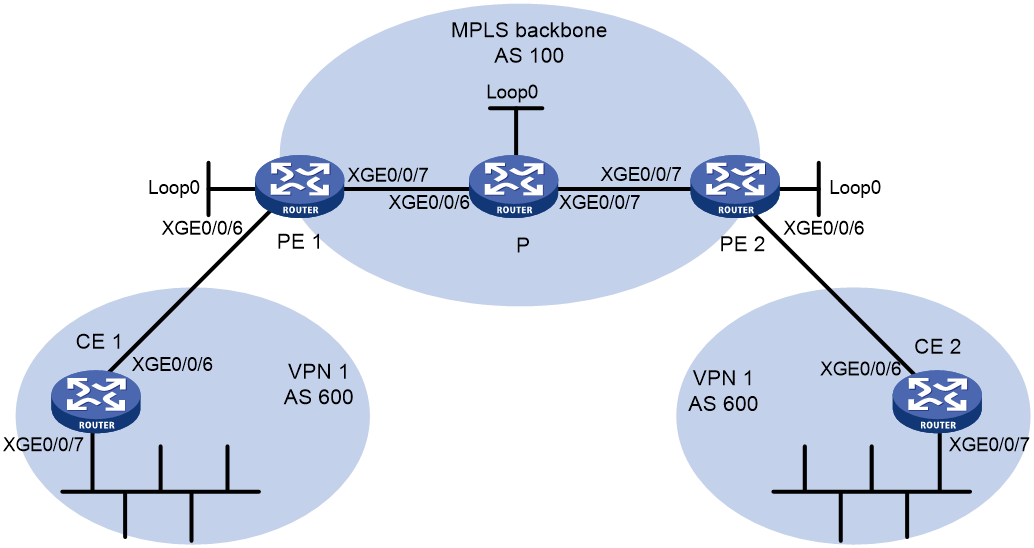
Table 9 Interface and IP address assignment
|
Device |
Interface |
IP address |
Device |
Interface |
IP address |
|
CE 1 |
XGE0/0/6 |
10:1::2/96 |
P |
Loop0 |
2.2.2.9/32 |
|
|
XGE0/0/7 |
100::1/96 |
|
XGE0/0/6 |
20.1.1.2/24 |
|
PE 1 |
Loop0 |
10.1.1.1/32 |
|
XGE0/0/7 |
30.1.1.1/24 |
|
|
XGE0/0/6 |
10:1::1/96 |
PE 2 |
Loop0 |
10.1.1.2/32 |
|
|
XGE0/0/7 |
20.1.1.1/24 |
|
XGE0/0/6 |
10:2::1/96 |
|
CE 2 |
XGE0/0/6 |
10:2::2/96 |
|
XGE0/0/7 |
30.1.1.2/24 |
|
|
XGE0/0/7 |
200::1/96 |
|
|
|
Procedure
1. Configure basic IPv6 MPLS L3VPN:
¡ Configure OSPF on the MPLS backbone to allow the PEs and P device to learn the routes of the loopback interfaces from each other.
¡ Configure basic MPLS and MPLS LDP on the MPLS backbone to establish LDP LSPs.
¡ Establish an MP-IBGP peer relationship between the PEs to advertise VPN IPv6 routes.
¡ Configure the VPN instance of VPN 1 on PE 1 to allow CE 1 to access the network.
¡ Configure the VPN instance of VPN 1 on PE 2 to allow CE 2 to access the network.
¡ Configure BGP as the PE-CE routing protocol, and redistribute routes of the CEs into the PEs.
For more information about basic IPv6 MPLS L3VPN configurations, see "Example: Configuring IPv6 MPLS L3VPNs."
# Execute the display ipv6 routing-table command on CE 2 to verify that CE 2 has not learned the route to the VPN (100::/96) behind CE 1.
<CE2> display ipv6 routing-table
Destinations : 6 Routes : 6
Destination: ::1/128 Protocol : Direct
NextHop : ::1 Preference: 0
Interface : InLoop0 Cost : 0
Destination: 10:2::/96 Protocol : Direct
NextHop : :: Preference: 0
Interface : XGE0/0/6 Cost : 0
Destination: 10:2::2/128 Protocol : Direct
NextHop : ::1 Preference: 0
Interface : InLoop0 Cost : 0
Destination: 200::/96 Protocol : Static
NextHop : :: Preference: 60
Interface : NULL0 Cost : 0
Destination: FE80::/10 Protocol : Direct
NextHop : :: Preference: 0
Interface : NULL0 Cost : 0
Destination: FF00::/8 Protocol : Direct
NextHop : :: Preference: 0
Interface : NULL0 Cost : 0
# Execute the display ipv6 routing-table command on CE 1 to verify that CE 1 has not learned the route to the VPN behind CE 2. (Details not shown.)
# Execute the display ipv6 routing-table vpn-instance command on the PEs. The output shows the route to the VPN behind the peer CE. This example uses PE 2.
<PE2> display ipv6 routing-table vpn-instance vpn1
Destinations : 7 Routes : 7
Destination: ::1/128 Protocol : Direct
NextHop : ::1 Preference: 0
Interface : InLoop0 Cost : 0
Destination: 10:2::/96 Protocol : Direct
NextHop : :: Preference: 0
Interface : XGE0/0/6 Cost : 0
Destination: 10:2::1/128 Protocol : Direct
NextHop : ::1 Preference: 0
Interface : InLoop0 Cost : 0
Destination: 100::/96 Protocol : BGP4+
NextHop : ::FFFF:10.1.1.1 Preference: 255
Interface : XGE0/0/7 Cost : 0
Destination: 200::/96 Protocol : BGP4+
NextHop : 10:2::2 Preference: 255
Interface : XGE0/0/6 Cost : 0
Destination: FE80::/10 Protocol : Direct
NextHop : :: Preference: 0
Interface : NULL0 Cost : 0
Destination: FF00::/8 Protocol : Direct
NextHop : :: Preference: 0
Interface : NULL0 Cost : 0
# Enable BGP update packet debugging on PE 2. The output shows that PE 2 has advertised the route for 100::/96, and the AS_PATH is 100 600.
<PE2> terminal monitor
<PE2> terminal logging level 7
<PE2> debugging bgp update vpn-instance vpn1 10:2::2 ipv6
<PE2> refresh bgp all export ipv6 vpn-instance vpn1
*Jun 13 16:12:52:096 2012 PE2 BGP/7/DEBUG:
BGP_IPV6.vpn1: Send UPDATE to update-group 0 for following destinations:
Origin : Incomplete
AS path : 100 600
Next hop : ::FFFF:10.1.1.1
100::/96,
*Jun 13 16:12:53:024 2012 PE2 BGP/7/DEBUG:
BGP.vpn1: Send UPDATE MSG to peer 10:2::2(IPv6-UNC) NextHop: 10:2::1.
# Execute the display bgp routing-table ipv6 peer received-routes command on CE 2 to verify that CE 2 has not received the route to 100::/96.
<CE2> display bgp routing-table ipv6 peer 10:2::1 received-routes
Total number of routes: 0
2. Configure BGP AS number substitution:
# Configure BGP AS number substitution on PE 1.
<PE1> system-view
[PE1] bgp 100
[PE1-bgp-default] ip vpn-instance vpn1
[PE1-bgp-default-vpn1] peer 10:1::2 substitute-as
[PE1-bgp-default-vpn1] quit
[PE1-bgp-default] quit
# Configure BGP AS number substitution on PE 2.
<PE2> system-view
[PE2] bgp 100
[PE2-bgp-default] ip vpn-instance vpn1
[PE2-bgp-default-vpn1] peer 10:2::2 substitute-as
[PE2-bgp-default-vpn1] quit
[PE2-bgp-default] quit
Verifying the configuration
# The output shows that among the routes advertised by PE 2 to CE 2, the AS_PATH of 100::/96 has changed from 100 600 to 100 100.
*Jun 27 18:07:34:420 2013 PE2 BGP/7/DEBUG:
BGP_IPV6.vpn1: Send UPDATE to peer 10:2::2 for following destinations:
Origin : Incomplete
AS path : 100 100
Next hop : 10:2::1
100::/96,
# Display again the routing information that CE 2 has received, and the routing table. The output shows that CE 2 has learned the route 100::/96.
<CE2> display bgp routing-table ipv6 peer 10:2::1 received-routes
Total number of routes: 1
BGP local router ID is 12.1.1.3
Status codes: * - valid, > - best, d - dampened, h - history,
s - suppressed, S - stale, i - internal, e - external
Origin: i - IGP, e - EGP, ? - incomplete
* >e Network : 100:: PrefixLen : 96
NextHop : 10:2::1 LocPrf :
PrefVal : 0 OutLabel : NULL
MED :
Path/Ogn: 100 100?
<CE2> display ipv6 routing-table
Destinations : 7 Routes : 7
Destination: ::1/128 Protocol : Direct
NextHop : ::1 Preference: 0
Interface : InLoop0 Cost : 0
Destination: 10:2::/96 Protocol : Direct
NextHop : :: Preference: 0
Interface : XGE0/0/6 Cost : 0
Destination: 10:2::2/128 Protocol : Direct
NextHop : ::1 Preference: 0
Interface : InLoop0 Cost : 0
Destination: 100::/96 Protocol : BGP4+
NextHop : 10:2::1 Preference: 255
Interface : XGE0/0/6 Cost : 0
Destination: 200::/96 Protocol : Static
NextHop : :: Preference: 60
Interface : NULL0 Cost : 0
Destination: FE80::/10 Protocol : Direct
NextHop : :: Preference: 0
Interface : NULL0 Cost : 0
Destination: FF00::/8 Protocol : Direct
NextHop : :: Preference: 0
Interface : NULL0 Cost : 0
# Verify that Ten-GigabitEthernet 0/0/7 of CE 1 and Ten-GigabitEthernet 0/0/7 of CE 2 can ping each other. (Details not shown.)
Example: Configuring BGP AS number substitution and SoO attribute
Network configuration
CE 1, CE 2, and CE 3 belong to VPN 1, and are connected to PE1, PE 2, and PE 3. CE 1 and CE 2 reside in the same site. CE1, CE2, and CE 3 all use AS number 600.
To avoid route loss, configure BGP AS number substitution on PEs.
To avoid routing loops, configure the same SoO attribute on PE 1 and PE 2 for CE 1 and CE 2.
Figure 13 Network diagram
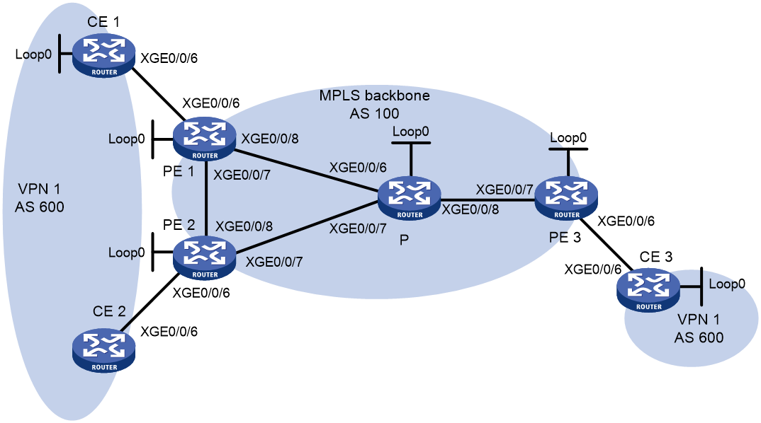
Table 10 Interface and IP address assignment
|
Device |
Interface |
IP address |
Device |
Interface |
IP address |
|
CE 1 |
Loop0 |
100::1/96 |
CE 3 |
Loop0 |
200::1/96 |
|
|
XGE0/0/6 |
10:1::1/96 |
|
XGE0/0/6 |
10:3::1/96 |
|
CE 2 |
XGE0/0/6 |
10:2::1/96 |
PE 2 |
Loop0 |
2.2.2.9/32 |
|
PE 1 |
Loop0 |
1.1.1.9/32 |
|
XGE0/0/6 |
10:2::2/96 |
|
|
XGE0/0/6 |
10:1::2/96 |
|
XGE0/0/7 |
40.1.1.1/24 |
|
|
XGE0/0/7 |
20.1.1.1/24 |
|
XGE0/0/8 |
20.1.1.2/24 |
|
|
XGE0/0/8 |
30.1.1.1/24 |
P |
Loop0 |
3.3.3.9/32 |
|
PE 3 |
Loop0 |
4.4.4.9/32 |
|
XGE0/0/6 |
30.1.1.2/24 |
|
|
XGE0/0/6 |
10:3::2/96 |
|
XGE0/0/7 |
40.1.1.2/24 |
|
|
XGE0/0/7 |
50.1.1.2/24 |
|
XGE0/0/8 |
50.1.1.1/24 |
Procedure
1. Configure basic IPv6 MPLS L3VPN:
¡ Configure OSPF on the MPLS backbone to allow the PEs and P device to learn the routes of the loopback interfaces from each other.
¡ Configure basic MPLS and MPLS LDP on the MPLS backbone to establish LDP LSPs.
¡ Establish an MP-IBGP peer relationship between the PEs to advertise VPN IPv6 routes.
¡ Configure the VPN instance of VPN 1 on PE 1 to allow CE 1 to access the network.
¡ Configure the VPN instance of VPN 1 on PE 2 to allow CE 2 to access the network.
¡ Configure the VPN instance of VPN 1 on PE 3 to allow CE 3 to access the network.
¡ Configure BGP as the PE-CE routing protocol, and redistribute routes of the CEs into the PEs.
For more information about basic MPLS L3VPN configurations, see "Example: Configuring IPv6 MPLS L3VPNs."
2. Configure BGP AS number substitution:
# Configure BGP AS number substitution on PE 1, PE 2, and PE 3. For more information about the configuration, see "Configuring MPLS L3VPN."
# Display routing information on CE 2. The output shows that CE 2 has learned the route 100::/96 from CE 1. A routing loop has occurred because CE 1 and CE 2 reside in the same site.
<CE2> display bgp routing-table ipv6 peer 10:2::2 received-routes
Total number of routes: 2
BGP local router ID is 12.1.1.3
Status codes: * - valid, > - best, d - dampened, h - history,
s - suppressed, S - stale, i - internal, e - external
Origin: i - IGP, e - EGP, ? - incomplete
* >e Network : 100:: PrefixLen : 96
NextHop : 10:2::2 LocPrf :
PrefVal : 0 OutLabel : NULL
MED :
Path/Ogn: 100 100?
* >e Network : 200:: PrefixLen : 96
NextHop : 10:2::2 LocPrf :
PrefVal : 0 OutLabel : NULL
MED :
Path/Ogn: 100 100?
3. Configure BGP SoO attribute:
# On PE 1, configure the SoO attribute as 1:100 for CE 1.
<PE1> system-view
[PE1] bgp 100
[PE1-bgp-default] ip vpn-instance vpn1
[PE1-bgp-default-vpn1] address-family ipv6
[PE1-bgp-default-ipv6-vpn1] peer 10:1::1 soo 1:100
# On PE 2, configure the SoO attribute as 1:100 for CE 2.
[PE2] bgp 100
[PE2-bgp-default] ip vpn-instance vpn1
[PE2-bgp-default-vpn1] address-family ipv6
[PE2-bgp-default-ipv6-vpn1] peer 10:2::1 soo 1:100
Verifying the configuration
# PE 2 does not advertise routes received from CE 1 to CE 2 because the same SoO attribute has been configured. Display the routing table of CE 2. The output shows that the route 100::/96 has been removed.
<CE2> display ipv6 routing-table
Destinations : 4 Routes : 4
Destination: ::1/128 Protocol : Direct
NextHop : ::1 Preference: 0
Interface : InLoop0 Cost : 0
Destination: 10:2::/96 Protocol : Direct
NextHop : :: Preference: 0
Interface : XGE0/0/6 Cost : 0
Destination: 10:2::1/128 Protocol : Direct
NextHop : ::1 Preference: 0
Interface : InLoop0 Cost : 0
Destination: 200::/96 Protocol : Static
NextHop : :: Preference: 60
Interface : NULL0 Cost : 0
