- Table of Contents
- Related Documents
-
| Title | Size | Download |
|---|---|---|
| 01-Hardware Information and Specifications | 996.73 KB |
1 Product models and technical specifications
S6530X-48Y8C and S6530X-48Y8C-G
S6530X-48X8C and S6530X-48X8C-G
S6530X-24Y8C and S6530X-24Y8C-G
S6530X-24X8C and S6530X-24X8C-G
3 Removable components and compatibility matrixes
1 Product models and technical specifications
Product models
Table1-1 Switch series and models
|
Model |
Product code (PID) |
|
|
S6530X switch series |
S6530X-48Y8C |
LS-6530X-48Y8C |
|
S6530X-48X8C |
LS-6530X-48X8C |
|
|
S6530X-24Y8C |
LS-6530X-24Y8C |
|
|
S6530X-24X8C |
LS-6530X-24X8C |
|
|
S6530X-G switch series |
S6530X-48Y8C-G |
LS-6530X-48Y8C-G1 |
|
S6530X-48X8C-G |
LS-6530X-48X8C-G1 |
|
|
S6530X-24Y8C-G |
LS-6530X-24Y8C-G1 |
|
|
S6530X-24X8C-G |
LS-6530X-24X8C-G1 |
Technical specifications
Table1-2 Technical specifications
|
Item |
S6530X-48Y8C S6530X-48Y8C-G |
S6530X-48X8C S6530X-48X8C-G |
S6530X-24Y8C S6530X-24Y8C-G |
S6530X-24X8C S6530X-24X8C-G |
|
Dimensions (H × W × D) |
44 × 440 × 400 mm (1.73 × 17.32 × 15.75 in) |
44 × 440 × 400 mm (1.73 × 17.32 × 15.75 in) |
44 × 440 × 400 mm (1.73 × 17.32 × 15.75 in) |
44 × 440 × 400 mm (1.73 × 17.32 × 15.75 in) |
|
Weight |
≤ 7.6 kg (16.75 lb) |
≤ 7.6 kg (16.75 lb) |
≤ 7.3 kg (16.09 lb) |
≤ 7.3 kg (16.09 lb) |
|
Console port |
1 × serial console port |
|||
|
USB port |
1 |
|||
|
Management Ethernet port |
1 |
|||
|
SFP+ port |
N/A |
48 |
N/A |
24 |
|
SFP28 port |
48 |
N/A |
24 |
N/A |
|
QSFP28 port |
8 |
8 |
8 |
8 |
|
Power supply slot |
2 |
|||
|
Fan tray slot |
5 |
|||
|
Input voltage |
AC input for the PSR250-12A/PSR250-12A1 power supply: · Rated voltage range: 100 VAC to 240 VAC @ 50 Hz or 60 Hz · Max voltage range: 90 VAC to 290 VAC @ 47 Hz to 63 Hz HVDC input for the PSR250-12A/PSR250-12A1 power supply: · Rated voltage: 240 VDC · Max voltage range: 180 VDC to 320 VDC PSR450-12D power supply: · Rated voltage range: –48 VDC to –60 VDC · Max voltage range: –36 VDC to –72 VDC DC power source for the PSR450-12D power supply: –48 VDC power source in the equipment room or an RPS (H3C RPS1600-A) |
|||
|
Minimum power consumption |
Single power input: 76 W Dual power inputs: 83 W |
Single power input: 76 W Dual power inputs: 83 W |
Single power input: 76 W Dual power inputs: 83 W |
Single power input: 76 W Dual power inputs: 83 W |
|
Maximum power consumption |
Single power input: 223 W Dual power inputs: 227 W |
Single power input: 217 W Dual power inputs: 221 W |
Single power input: 188 W Dual power inputs: 193 W |
Single power input: 186 W Dual power inputs: 191 W |
|
Chassis leakage current compliance |
UL62368-1/EN62368-1/IEC62368-1/UL60950-1/IEC60950-1/GB4943.1 |
|||
|
Melting current of power supply fuse |
PSR250-12A/PSR250-12A1 power supply: 6.3 A/250 V PSR450-12D power supply: 20 A/125 V |
|||
|
Operating temperature |
–5°C to +45°C (23°F to 113°F) |
|||
|
Operating humidity |
5% RH to 95% RH, noncondensing |
|||
|
Fire resistance compliance |
UL62368-1/EN62368-1/IEC62368-1/UL60950-1/IEC60950-1/GB4943.1 |
|||
2 Chassis views
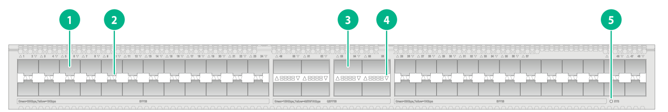
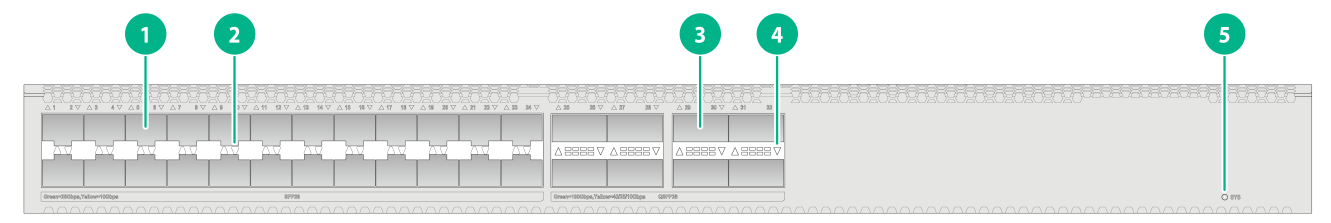
S6530X-48Y8C and S6530X-48Y8C-G
Figure2-1 Front panel
|
(1) SFP28 port |
(2) SFP28 port LED |
|
(3) QSFP28 port |
(4) QSFP28 port LED |
|
(5) System status LED (SYS) |
|

|
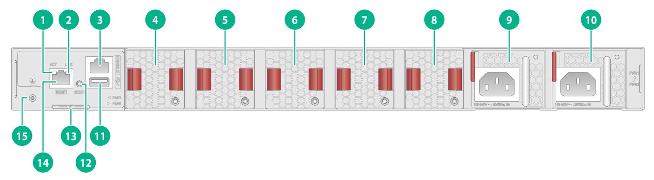
(1) Management Ethernet port LED (ACT) |
(2) Management Ethernet port LED (LINK) |
|
(3) Console port |
(4) Fan tray 1 |
|
(5) Fan tray 2 |
(6) Fan tray 3 |
|
(7) Fan tray 4 |
(8) Fan tray 5 |
|
(9) Power supply 1 |
(10) Power supply 2 |
|
(11) USB port |
(12) Reset button (RESET) |
|
(13) Serial label pull tab |
(14) Management Ethernet port (MGMT) |
|
(15) Grounding screw |
|
The SN serial number and MAC address of the S6530X-48Y8C/S6530X-48Y8C-G switch can be found on the serial label pull tab.
The S6530X-48Y8C/S6530X-48Y8C-G switch came with power supply slot 1 empty and power supply slot 2 installed with a filler panel. You can install one or two power supplies for the switch as required. In Figure2-2, two PSR250-12A1 AC power supplies are installed in the power supply slots.
The S6530X-48Y8C/S6530X-48Y8C-G switch came with five fan tray slots empty. You must install five fan trays of the same model for the switch. In Figure2-2, five LSPM1FANSB-SN fan trays are installed in the fan tray slots.
The S6530X-48Y8C/S6530X-48Y8C-G switch provides a reset button on the rear panel for you to reset the switch.
To use both the console port and USB port on the S6530X-48Y8C/S6530X-48Y8C-G switch, use a small-sized USB drive or a USB extension cable.
The S6530X/S6530X-G switch series supports shipping with fan trays and power supplies installed. For the switch to be shipped with fan trays or power supplies installed, contact the marketing staff.
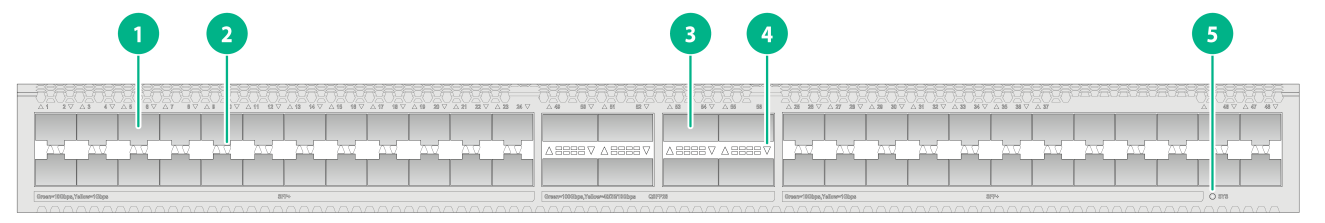
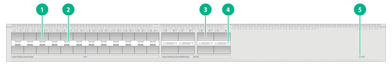
S6530X-48X8C and S6530X-48X8C-G
Figure2-3 Front panel
|
(1) SFP+ port |
(2) SFP+ port LED |
|
(3) QSFP28 port |
(4) QSFP28 port LED |
|
(5) System status LED (SYS) |
|
|
(1) Management Ethernet port LED (ACT) |
(2) Management Ethernet port LED (LINK) |
|
(3) Console port |
(4) Fan tray 1 |
|
(5) Fan tray 2 |
(6) Fan tray 3 |
|
(7) Fan tray 4 |
(8) Fan tray 5 |
|
(9) Power supply 1 |
(10) Power supply 2 |
|
(11) USB port |
(12) Reset button (RESET) |
|
(13) Serial label pull tab |
(14) Management Ethernet port (MGMT) |
|
(15) Grounding screw |
|
The SN serial number and MAC address of the S6530X-48X8C/S6530X-48X8C-G switch can be found on the serial label pull tab.
The S6530X-48X8C/S6530X-48X8C-G switch came with power supply slot 1 empty and power supply slot 2 installed with a filler panel. You can install one or two power supplies for the switch as required. In Figure2-4, two PSR250-12A1 AC power supplies are installed in the power supply slots.
The S6530X-48X8C/S6530X-48X8C-G switch came with five fan tray slots empty. You must install five fan trays of the same model for the switch. In Figure2-4, five LSPM1FANSB-SN fan trays are installed in the fan tray slots.
The S6530X-48X8C/S6530X-48X8C-G switch provides a reset button on the rear panel for you to reset the switch.
To use both the console port and USB port on the S6530X-48X8C/S6530X-48X8C-G switch, use a small-sized USB drive or a USB extension cable.
The S6530X/S6530X-G switch series supports shipping with fan trays and power supplies installed. For the switch to be shipped with fan trays or power supplies installed, contact the marketing staff.
S6530X-24Y8C and S6530X-24Y8C-G
Figure2-5 Front panel
|
(1) SFP28 port |
(2) SFP28 port LED |
|
(3) QSFP28 port |
(4) QSFP28 port LED |
|
(5) System status LED (SYS) |
|

|
(1) Management Ethernet port LED (ACT) |
(2) Management Ethernet port LED (LINK) |
|
(3) Console port |
(4) Fan tray 1 |
|
(5) Fan tray 2 |
(6) Fan tray 3 |
|
(7) Fan tray 4 |
(8) Fan tray 5 |
|
(9) Power supply 1 |
(10) Power supply 2 |
|
(11) USB port |
(12) Reset button (RESET) |
|
(13) Serial label pull tab |
(14) Management Ethernet port (MGMT) |
|
(15) Grounding screw |
|
The SN serial number and MAC address of the S6530X-24Y8C/S6530X-24Y8C-G switch can be found on the serial label pull tab.
The S6530X-24Y8C/S6530X-24Y8C-G switch came with power supply slot 1 empty and power supply slot 2 installed with a filler panel. You can install one or two power supplies for the switch as required. In Figure2-6, two PSR250-12A1 AC power supplies are installed in the power supply slots.
The S6530X-24Y8C/S6530X-24Y8C-G switch came with five fan tray slots empty. You must install five fan trays of the same model for the switch. In Figure2-6, five LSPM1FANSB-SN fan trays are installed in the fan tray slots.
The S6530X-24Y8C/S6530X-24Y8C-G switch provides a reset button on the rear panel for you to reset the switch.
To use both the console port and USB port on the S6530X-24Y8C/S6530X-24Y8C-G switch, use a small-sized USB drive or a USB extension cable.
The S6530X/S6530X-G switch series supports shipping with fan trays and power supplies installed. For the switch to be shipped with fan trays or power supplies installed, contact the marketing staff.
S6530X-24X8C and S6530X-24X8C-G
Figure2-7 Front panel
|
(1) SFP+ port |
(2) SFP+ port LED |
|
(3) QSFP28 port |
(4) QSFP28 port LED |
|
(5) System status LED (SYS) |
|

|
(1) Management Ethernet port LED (ACT) |
(2) Management Ethernet port LED (LINK) |
|
(3) Console port |
(4) Fan tray 1 |
|
(5) Fan tray 2 |
(6) Fan tray 3 |
|
(7) Fan tray 4 |
(8) Fan tray 5 |
|
(9) Power supply 1 |
(10) Power supply 2 |
|
(11) USB port |
(12) Reset button (RESET) |
|
(13) Serial label pull tab |
(14) Management Ethernet port (MGMT) |
|
(15) Grounding screw |
|
The SN serial number and MAC address of the S6530X-24X8C/S6530X-24X8C-G switch can be found on the serial label pull tab.
The S6530X-24X8C/S6530X-24X8C-G switch came with power supply slot 1 empty and power supply slot 2 installed with a filler panel. You can install one or two power supplies for the switch as required. In Figure2-8, two PSR250-12A1 AC power supplies are installed in the power supply slots.
The S6530X-24X8C/S6530X-24X8C-G switch came with five fan tray slots empty. You must install five fan trays of the same model for the switch. In Figure2-8, five LSPM1FANSB-SN fan trays are installed in the fan tray slots.
The S6530X-24X8C/S6530X-24X8C-G switch provides a reset button on the rear panel for you to reset the switch.
To use both the console port and USB port on the S6530X-24X8C/S6530X-24X8C-G switch, use a small-sized USB drive or a USB extension cable.
The S6530X/S6530X-G switch series supports shipping with fan trays and power supplies installed. For the switch to be shipped with fan trays or power supplies installed, contact the marketing staff.
3 Removable components and compatibility matrixes
The switch supports removable components. Table3-1 describes the removable components available for the switch.
Table3-1 Compatibility matrix between switches and removable components
|
FRU model |
S6530X-48Y8C S6530X-48X8C S6530X-24Y8C S6530X-24X8C S6530X-48Y8C-G S6530X-48X8C-G S6530X-24Y8C-G S6530X-24X8C-G |
|
Removable power supplies |
|
|
PSR250-12A |
Supported |
|
PSR250-12A1 |
Supported |
|
PSR450-12D |
Supported |
|
Removable fan trays |
|
|
LSPM1FANSA-SN |
Supported |
|
LSPM1FANSB-SN |
Supported |
The power supplies support asset management. You can use the display device manuinfo command to view the name, sequence number, and vendor of the power supply you have installed on the switch.
The switch provides two power supply slots. One power supply can meet the power requirement of the switch. You can install two power supplies on the switch for 1+1 redundancy. Do not install power supplies of different models on the same switch.
The switch uses removable fan trays. Do not power on the switch if it does not have five fan trays of the same model installed.
Removable power supplies
Table3-2 Power supplies available for the switch
|
Power supply model |
AC or DC input |
Specifications |
|
PSR250-12A PSR250-12A1 |
AC input |
· Rated input voltage range: 100 to 240 VAC @ 50/60 Hz · Max input voltage range: 90 to 290 VAC @ 47 to 63 Hz · Max output power: 250 W |
|
HVDC input |
· Rated input voltage: 240 VDC · Max input voltage range: 180 to 320 VDC · Max output power: 250 W |
|
|
PSR450-12D |
DC input |
· Rated input voltage range: –48 VDC to –60 VDC · Max input voltage range: –36 VDC to –72 VDC · Max output power: 450 W |
Removable fan trays
Table3-3 Fan tray specifications
|
Fan tray model |
Item |
Specifications |
|
· LSPM1FANSA-SN (from the power supply side to the port side) · LSPM1FANSB-SN (from the port side to the power supply side) |
Quantity |
One 40 × 40.6 × 105 mm (1.57 × 1.60 × 4.13 in) fan |
|
Fan speed |
20000 R.P.M |
|
|
Max airflow |
20 CFM (0.57 m3/min) |
|
|
Input voltage |
12 V |
|
|
Power consumption |
9.8 W |
|
|
Documentation reference |
H3C LSPM1FANSA-SN & LSPM1FANSB-SN Fan Trays User Guide |
4 Ports and LEDs
Ports
Console port
Table4-1 Console port specifications
|
Item |
Specification |
|
Connector type |
RJ-45 |
|
Compliant standard |
EIA/TIA-232 |
|
Port transmission rate |
9600 bps (default) to 115200 bps |
|
Services |
· Provides connection to an ASCII terminal · Provides connection to the serial port of a local PC running terminal emulation program |
|
Compatible devices |
All device models |
Management Ethernet port
Table4-2 Management Ethernet port specifications
|
Item |
Specification |
|
Connector type |
RJ-45 |
|
Port transmission rate |
· 10 Mbps, half/full duplex · 100 Mbps, half/full duplex · 1000 Mbps, full duplex · MDI/MDI-X autosensing |
|
Transmission medium |
Category-5 or above twisted pair cable |
|
Max transmission distance |
100 m (328.08 ft) |
|
Compliant standard |
IEEE 802.3i, 802.3u, and 802.3ab |
|
Functions and services |
Switch software and Boot ROM upgrade, network management |
|
Compatible devices |
All device models |
|
Usage guidelines |
Do not forcibly configure a management Ethernet port to operate at 1000 Mbps in full duplex mode. |
USB port
Table4-3 USB port specifications
|
Item |
Specification |
|
Interface type |
USB 2.0 |
|
Compliant standard |
OHC |
|
Port transmission rate |
Uploads and downloads data at a rate up to 480 Mbps |
|
Functions and services |
Accesses the file system on the flash of the switch, for example, to upload or download application and configuration files |
|
Compatible devices |
All device models |
|
|
NOTE: USB devices from different vendors vary in compatibilities and drivers. H3C does not guarantee correct operation of USB devices from other vendors on the switch. If a USB device fails to operate on the switch, replace it with one from another vendor. |
SFP+ port
Table4-4 SFP+ port specifications
|
Item |
Specification |
|
Interface type |
SFP+ port |
|
Compatible transceiver modules and cables |
· 10GE SFP+ transceiver modules and cables in Table4-5, Table4-6, and Table4-7 · GE SFP transceiver modules and cables in Table4-8 |
|
Compatible devices |
S6530X-48X8C, S6530X-24X8C, S6530X-48X8C-G, and S6530X-24X8C-G switches |
|
Restrictions and guidelines |
Follow these restrictions and guidelines when you use the SFP-10GE-T copper transceiver module: · Support for the SFP-10GE-T copper transceiver module depends on the software version. For more information, see the corresponding software release notes. · Do not install 10G copper transceiver modules in adjacent fiber ports and do not install any other modules in ports adjacent to the ports installed with 10G copper transceiver modules. You can install a maximum of 20 copper transceiver modules. · Do not install copper transceiver modules in the four ports adjacent to a 100G port. Follow these restrictions and guidelines when you use the SFP-GE-T or SFP-GE-T-D copper transceiver module: · Support for the SFP-GE-T and SFP-GE-T-D copper transceiver modules depends on the software version. For more information, see the corresponding software release notes. · There are no usage restrictions if you install the LSPM1FANSA-SN fan trays on the switch. Follow these restrictions and guidelines when you use 10G SFP+ transceiver modules with a maximum transmission distance of 80 km (49.71 miles): · Support for the transceiver modules depends on the software version. For more information, see the corresponding software release notes. · If you install the LSPM1FANSA-SN fan trays on the switch and the operating temperature is not higher than 40°C (104°F), there are no usage restrictions. · If you install the LSPM1FANSA-SN fan trays on the device and the operating temperature is above 40°C (104°F), do not install the transceiver modules in adjacent ports. |
Table4-5 10GE SFP+ transceiver modules and copper interface modules available for the SFP+ ports
|
Type |
10GE SFP+ transceiver module |
Central wavelength (nm) |
Connector |
Fiber diameter (µm) |
Modal bandwidth (MHz × km) |
Max transmission distance |
|
SFP+ transceiver modules |
SFP-XG-SX-MM850-D |
850 |
LC |
Multi-mode, 50/125 |
2000 |
300 m (984.25 ft) |
|
500 |
82 m (269.03 ft) |
|||||
|
400 |
66 m (216.54 ft) |
|||||
|
Multi-mode, 62.5/125 |
200 |
33 m (108.27 ft) |
||||
|
160 |
26 m (85.30 ft) |
|||||
|
SFP-XG-LX-SM1310-E |
1310 |
LC |
Single-mode, 9/125 |
N/A |
10 km (6.21 miles) |
|
|
SFP-XG-LX-SM1310 |
1310 |
LC |
Single-mode, 9/125 |
N/A |
10 km (6.21 miles) |
|
|
SFP-XG-LX-SM1310-D |
1310 |
LC |
Single-mode, 9/125 |
N/A |
10 km (6.21 miles) |
|
|
SFP-XG-LH40-SM1550 |
1550 |
LC |
Single-mode, 9/125 |
N/A |
40 km (24.86 miles) |
|
|
SFP-XG-LH40-SM1550-D |
1550 |
LC |
Single-mode, 9/125 |
N/A |
40 km (24.86 miles) |
|
|
SFP-XG-LH80-SM1550 |
1550 |
LC |
Single-mode, 9/125 |
N/A |
80 km (49.71 miles) |
|
|
SFP-XG-LH80-SM1550-D |
1550 |
LC |
Single-mode, 9/125 |
N/A |
80 km (49.71 miles) |
|
|
SFP-XG-LX-SM1270-BIDI |
TX: 1270 RX: 1330 |
LC |
Single-mode, 9/125 |
N/A |
10 km (6.21 miles) |
|
|
SFP-XG-LX-SM1330-BIDI |
TX: 1330 RX: 1270 |
LC |
Single-mode, 9/125 |
N/A |
10 km (6.21 miles) |
|
|
SFP-XG-LH40-SM1270-BIDI |
TX: 1270 RX: 1330 |
LC |
Single-mode, 9/125 |
N/A |
40 km (24.86 miles) |
|
|
SFP-XG-LH40-SM1330-BIDI |
TX: 1330 RX: 1270 |
LC |
Single-mode, 9/125 |
N/A |
40 km (24.86 miles) |
|
|
SFP-XG-LH80-SM1490-BIDI |
TX: 1490 RX: 1550 |
LC |
Single-mode, 9/125 |
N/A |
80 km (49.71 miles) |
|
|
SFP-XG-LH80-SM1550-BIDI |
TX: 1550 RX: 1490 |
LC |
Single-mode, 9/125 |
N/A |
80 km (49.71 miles) |
|
|
Copper transceiver modules |
SFP-10GE-T |
N/A |
RJ-45 |
Category 6a STP or Category 7 STP |
N/A |
30 m (98.43 ft) |
|
|
IMPORTANT: The SFP-XG-LX-SM1270-BIDI and SFP-XG-LX-SM1330-BIDI transceiver modules, SFP-XG-LH40-SM1270-BIDI and SFP-XG-LH40-SM1330-BIDI transceiver modules, and SFP-XG-LH80-SM1490-BIDI and SFP-XG-LH80-SM1550-BIDI transceiver modules must be used in pairs. For example, if one end uses an SFP-XG-LX-SM1270-BIDI transceiver module, the other end must use an SFP-XG-LX-SM1330-BIDI transceiver module. |
Table4-6 SFP+ copper cables available for the SFP+ ports
|
SFP+ copper cable |
Cable length |
|
LSWM1STK |
0.65 m (2.13 ft) |
|
LSWM2STK |
1.2 m (3.94 ft) |
|
LSWM3STK |
3 m (9.84 ft) |
|
LSTM1STK |
5 m (16.40 ft) |
Table4-7 SFP+ fiber cables available for the SFP+ ports
|
SFP+ fiber cable |
Cable length |
|
SFP-XG-D-AOC-7M |
7 m (22.97 ft) |
|
SFP-XG-D-AOC-10M |
10 m (32.81 ft) |
|
SFP-XG-D-AOC-20M |
20 m (65.62 ft) |
Table4-8 GE SFP transceiver modules and cables available for the SFP+ ports
|
GE SFP transceiver module and cable |
Central wavelength (nm) |
Connector |
Cable/Fiber type and diameter (µm) |
Modal bandwidth (MHz × km) |
Max transmission distance |
|
SFP copper transceiver modules |
|||||
|
SFP-GE-T |
N/A |
RJ-45 |
Twisted pair cable |
N/A |
100 m (328.08 ft) |
|
SFP-GE-T-D |
N/A |
RJ-45 |
Twisted pair cable |
N/A |
100 m (328.08 ft) |
|
SFP fiber transceiver modules |
|||||
|
SFP-GE-SX-MM850-A |
850 |
LC |
Multi-mode, 50/125 |
500 |
550 m (1804.46 ft) |
|
400 |
500 m (1640.42 ft) |
||||
|
Multi-mode, 62.5/125 |
200 |
275 m (902.23 ft) |
|||
|
160 |
220 m (721.78 ft) |
||||
|
SFP-GE-SX-MM850-D |
850 |
LC |
Multi-mode, 50/125 |
500 |
550 m (1804.46 ft) |
|
400 |
500 m (1640.42 ft) |
||||
|
Multi-mode, 62.5/125 |
200 |
275 m (902.23 ft) |
|||
|
160 |
220 m (721.78 ft) |
||||
|
SFP-GE-LX-SM1310-A |
1310 |
LC |
Single-mode, 9/125 |
N/A |
10 km (6.21 miles) |
|
Multi-mode, 50/125 |
500 or 400 |
550 m (1804.46 ft) |
|||
|
Multi-mode, 62.5/125 |
500 |
550 m (1804.46 ft) |
|||
|
SFP-GE-LH40-SM1310 |
1310 |
LC |
Single-mode, 9/125 |
N/A |
40 km (24.86 miles) |
|
SFP-GE-LH40-SM1310-D |
1310 |
LC |
Single-mode, 9/125 |
N/A |
40 km (24.86 miles) |
|
SFP-GE-LH40-SM1550 |
1550 |
LC |
Single-mode, 9/125 |
N/A |
40 km (24.86 miles) |
|
SFP-GE-LH80-SM1550 |
1550 |
LC |
Single-mode, 9/125 |
N/A |
80 km (49.71 miles) |
|
SFP-GE-LH80-SM1550-D |
1550 |
LC |
Single-mode, 9/125 |
N/A |
80 km (49.71 miles) |
|
SFP-GE-LH100-SM1550 |
1550 |
LC |
Single-mode, 9/125 |
N/A |
100 km (62.14 miles) |
|
SFP-GE-LX-SM1310-BIDI |
TX: 1310 RX: 1490 |
LC |
Single-mode, 9/125 |
N/A |
10 km (6.21 miles) |
|
SFP-GE-LX-SM1490-BIDI |
TX: 1490 RX: 1310 |
LC |
Single-mode, 9/125 |
N/A |
10 km (6.21 miles) |
|
SFP-GE-LH40-SM1310-BIDI |
TX: 1310 RX: 1550 |
LC |
Single-mode, 9/125 |
N/A |
40 km (24.86 miles) |
|
SFP-GE-LH40-SM1550-BIDI |
TX: 1550 RX: 1310 |
LC |
Single-mode, 9/125 |
N/A |
40 km (24.86 miles) |
|
SFP cable |
|||||
|
SFP-STACK-Kit |
N/A |
N/A |
SFP cable |
N/A |
1.5 m (4.92 ft) |
|
|
IMPORTANT: The SFP-GE-LX-SM1310-BIDI and SFP-GE-LX-SM1490-BIDI transceiver modules and SFP-GE-LH40-SM1310-BIDI and SFP-GE-LH40-SM1550-BIDI transceiver modules must be used in pairs. For example, if one end uses the SFP-GE-LX-SM1310-BIDI transceiver module, the other end must use the SFP-GE-LX-SM1490-BIDI transceiver module. |
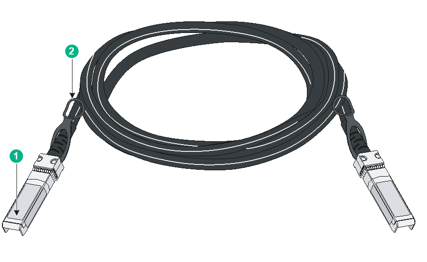
Figure4-1 SFP+ cable

|
(1) Connector |
(2) Pull latch |
|
|
NOTE: The H3C transceiver modules and network cables are subject to change over time. For the most recent list of H3C transceiver modules and cables, contact H3C Support or marketing staff. |
SFP28 port
Table4-9 SFP28 port specifications
|
Item |
Specification |
|
Interface type |
SFP28 port |
|
Compatible transceiver modules and cables |
· SFP28 transceiver modules and cables in Table4-10 and Table4-11 · 10GE SFP+ transceiver modules and cables in Table4-5, Table4-6, and Table4-7 · GE SFP transceiver modules and cables in Table4-8 |
|
Compatible devices |
S6530X-48Y8C, S6530X-24Y8C, S6530X-48Y8C-G, and S6530X-24Y8C-G |
|
Restrictions and guidelines |
Follow these restrictions and guidelines when you use the SFP-10GE-T copper transceiver module: · Support for the SFP-10GE-T copper transceiver module depends on the software version. For more information, see the corresponding software release notes. · Do not install 10G copper transceiver modules in adjacent fiber ports and do not install any other modules in ports adjacent to the ports installed with 10G copper transceiver modules. You can install a maximum of 20 copper transceiver modules. · Do not install copper transceiver modules in the four ports adjacent to a 100G port. Follow these restrictions and guidelines when you use the SFP-GE-T or SFP-GE-T-D copper transceiver module: · Support for the SFP-GE-T and SFP-GE-T-D copper transceiver modules depends on the software version. For more information, see the corresponding software release notes. · There are no usage restrictions if you install the LSPM1FANSA-SN fan trays on the switch. Follow these restrictions and guidelines when you use 10G SFP+ transceiver modules with a maximum transmission distance of 80 km (49.71 miles): · Support for the transceiver modules depends on the software version. For more information, see the corresponding software release notes. · If you install the LSPM1FANSA-SN fan trays on the switch and the operating temperature is not higher than 40°C (104°F), there are no usage restrictions. · If you install the LSPM1FANSA-SN fan trays on the device and the operating temperature is above 40°C (104°F), do not install the transceiver modules in adjacent ports. |
Table4-10 SFP28 transceiver modules available for the SFP28 ports
|
SFP28 transceiver module |
Central wavelength (nm) |
Connector |
Cable/Fiber type and diameter (µm) |
Modal bandwidth (MHz × km) |
Max transmission distance |
|
SFP-25G-SR-MM850 |
850 |
LC |
Multi-mode, 50/125 |
2000 |
70 m (229.66 ft) |
|
4700 |
100 m (328.08 ft) |
||||
|
SFP-25G-LR-SM1310 |
1310 |
LC |
Single-mode, 9/125 |
N/A |
10 km (6.21 miles) |
Table4-11 SFP28 cables available for the SFP28 ports
|
SFP28 cable |
Cable length |
|
SFP-25G-D-CAB-1M |
1 m (3.28 ft) |
|
SFP-25G-D-CAB-3M |
3 m (9.84 ft) |
|
SFP-25G-D-CAB-5M |
5 m (16.40 ft) |
|
(1) Connector |
(2) Pull latch |
|
|
NOTE: The H3C transceiver modules and cables are subject to change over time. For the most recent list of H3C transceiver modules and cables, contact your H3C Support or marketing staff. |
QSFP28 ports
Table4-12 QSFP28 port specifications
|
Item |
Specification |
|
Interface type |
QSFP28 port |
|
Compatible transceiver modules and cables |
· QSFP28 transceiver modules and cables in Table4-13, Table4-14, Table4-15, and Table4-16 · QSFP+ transceiver modules and cables in Table4-17, Table4-18, Table4-19, and Table4-20 |
|
Compatible devices |
All device models |
|
Usage guidelines |
· On an S6530X-48X8C or S6530X-24X8C switch, a QSFP28 port operates at 40 Gbps by default. You can increase the port speed to 100 Gbps by installing a license. To have the port operate at 100 Gbps, active the license by executing the active port basic-license command. For more information about the command, see Ethernet interface commands in the command reference for the switch. · You can install two types of licenses on the S6530X-48X8C or S6530X-24X8C switch to increase the speed of two or four QSFP28 ports to 100 Gbps. · You can install multiple licenses on the S6530X-48X8C or S6530X-24X8C switch and increase the speed of a maximum of eight QSFP28 ports to 100 Gbps. · For more information about licenses, see H3C Switches & Routers Licensing Guide. · When you connect an S6530X-24Y8C, S6530X-24Y8C-G, S6530X-48Y8C, or S6530X-48Y8C-G switch to a device (not an S6530X switch) through a SFP28 port installed with a 25G transceiver module, make sure the two ports on the local and peer ends are in the same FEC mode. |
Table4-13 QSFP28 transceiver modules available for the QSFP28 ports
|
QSFP28 transceiver module |
Central wavelength (nm) |
Connector |
Fiber type and diameter (µm) |
Modal bandwidth (MHz*km) |
Maximum transmission distance |
|
QSFP-100G-SR4-MM850 |
850 |
MPO |
Multi-mode, 50/125 |
2000 |
70 m (229.66 ft) |
|
4700 |
100 m (328.08 ft) |
||||
|
QSFP-100G-eSR4-MM850 |
850 |
MPO |
Multi-mode, 50/125 |
4700 |
300 m (984.25 ft) |
|
QSFP-100G-LR4-WDM1300 |
Four lanes: · 1295.56 · 1300.05 · 1304.58 · 1309.14 |
LC |
Single mode, 9/125 |
N/A |
10 km (6.21 miles) |
|
QSFP-100G-LR4L-WDM1300 |
Four lanes: · 1271 · 1291 · 1311 · 1331 |
LC |
Single mode, 9/125 |
N/A |
2 km (1.24 miles) |
|
QSFP-100G-ER4L-WDM1300 |
Four lanes: · 1295.56 · 1300.05 · 1304.58 · 1309.14 |
LC |
Single mode, 9/125 |
N/A |
40 km (24.86 miles) |
Table4-14 100G QSFP28 fiber cables available for the QSFP28 ports
|
QSFP28 fiber cable |
Cable length |
|
QSFP-100G-D-AOC-7M |
7 m (22.97 ft) |
|
QSFP-100G-D-AOC-10M |
10 m (32.81 ft) |
Table4-15 QSFP28 to SFP28 copper cables available for the QSFP28 ports
|
QSFP28 fiber cable |
Cable length |
|
QSFP-100G-4SFP-25G-CAB-1M |
1 m (3.28 ft) |
|
QSFP-100G-4SFP-25G-CAB-3M |
3 m (9.84 ft) |
|
QSFP-100G-4SFP-25G-CAB-5M |
5 m (16.40 ft) |
Table4-16 100G QSFP28 copper cables available for the QSFP28 ports
|
QSFP28 copper cable |
Cable length |
|
QSFP-100G-D-CAB-1M |
1 m (3.28 ft) |
|
QSFP-100G-D-CAB-3M |
3 m (9.84 ft) |
|
QSFP-100G-D-CAB-5M |
5 m (16.40 ft) |
Table4-17 QSFP+ transceiver modules available for the QSFP28 ports
|
QSFP+ transceiver module |
Central wavelength (nm) |
Connector |
Fiber type and diameter (µm) |
Modal bandwidth (MHz × km) |
Max transmission distance |
|
QSFP-40G-SR4-MM850 |
850 |
MPO |
Multi-mode, 50/125 |
2000 |
100 m (328.08 ft) |
|
4700 |
150 m (492.13 ft) |
||||
|
QSFP-40G-CSR4-MM850 |
850 |
MPO |
Multi-mode, 50/125 |
2000 |
300 m (984.25 ft) |
|
4700 |
400 m (1312.34 ft) |
||||
|
QSFP-40G-BIDI-SR-MM850 |
Two lanes: · 850 · 900 |
LC |
Multi-mode, 50/125 |
2000 |
100 m (328.08 ft) |
|
4700 |
150 m (492.13 ft) |
||||
|
QSFP-40G-LR4-WDM1300 |
Four lanes: · 1271 · 1291 · 1311 · 1331 |
LC |
Single-mode, 9/125 |
N/A |
10 km (6.21 miles) |
|
QSFP-40G-LR4L-WDM1300 |
Four lanes: · 1271 · 1291 · 1311 · 1331 |
LC |
Single-mode, 9/125 |
N/A |
2 km (1.24 miles) |
|
QSFP-40G-ER4-WDM1300 |
Four lanes: · 1271 · 1291 · 1311 · 1331 |
LC |
Single-mode, 9/125 |
N/A |
40 km (24.86 miles) |
Table4-18 40G QSFP+ copper cables available for the QSFP28 ports
|
QSFP+ copper cable |
Max transmission distance |
|
LSWM1QSTK0 |
1 m (3.28 ft) |
|
LSWM1QSTK1 |
3 m (9.84 ft) |
|
LSWM1QSTK2 |
5 m (16.40 ft) |
Table4-19 QSFP+ to SFP+ copper cables available for the QSFP28 ports
|
QSFP+ copper cable |
Max transmission distance |
|
LSWM1QSTK3 |
1 m (3.28 ft) |
|
LSWM1QSTK4 |
3 m (9.84 ft) |
|
LSWM1QSTK5 |
5 m (16.40 ft) |
Table4-20 40G QSFP+ fiber cables available for the QSFP28 ports
|
QSFP+ fiber cable |
Max transmission distance |
|
QSFP-40G-D-AOC-7M |
7 m (22.97 ft) |
|
QSFP-40G-D-AOC-20M |
20 m (65.62 ft) |
Figure4-3 100G QSFP28/40G QSFP+ copper cable
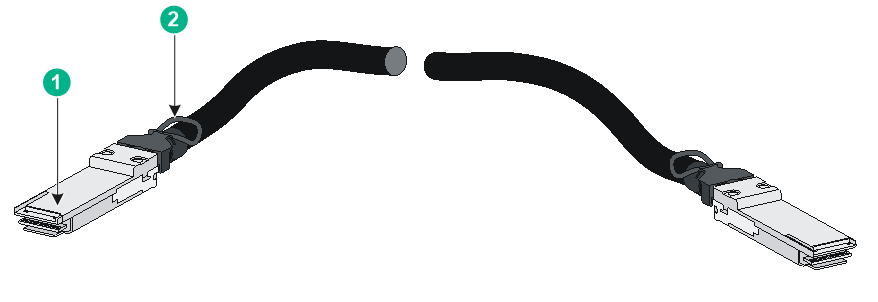
|
(1) Connector |
(2) Pull tab |
|
|
NOTE: The H3C transceiver modules and cables are subject to change over time. For the most recent list of H3C transceiver modules and cables, contact your H3C Support or marketing staff. |
LEDs
System status LED
The system status LED shows the operating status of the switch.
Table4-21 System status LED description
|
LED mark |
Status |
Description |
|
SYS |
Steady green |
The switch has started correctly. |
|
Flashing green (1 Hz) |
The switch is performing power-on self test (POST). |
|
|
Steady red |
The switch has failed the POST or is faulty. |
|
|
Flashing yellow |
The mode LED is used for switch locating. You can configure the mode LED to flash yellow by executing the locator blink command to locate the switch. |
|
|
Off |
The switch is powered off. |
Management Ethernet port LED
Table4-22 Management Ethernet port LED description
|
LED mark |
Status |
Description |
|
LINK |
Off |
No link is present on the port |
|
Steady green |
The port is operating at 10/100/1000 Mbps. |
|
|
ACT |
Off |
The port is not receiving or sending data. |
|
Flashing yellow |
The port is sending or receiving data. |
QSFP28 port LED
Table4-23 QSFP28 port LED description
|
LED status |
Description |
|
Steady green |
A transceiver module or cable has been correctly installed. The port has a link and is operating at 100 Gbps. |
|
Flashing green |
The port is sending or receiving data at 100 Gbps. |
|
Steady yellow |
A transceiver module or cable has been correctly installed. The port has a link and is operating at 10 Gbps, 25 Gbps, or 40 Gbps. |
|
Flashing yellow |
The port is sending or receiving data at 10 Gbps, 25 Gbps, or 40 Gbps. |
|
Off |
No transceiver module or cable has been installed or no link is present on the port. |
SFP28 port LEDs
Table4-24 SFP28 port LED description
|
LED status |
Description |
|
Steady green |
A transceiver module or cable has been correctly installed. The port has a link and is operating at 25 Gbps. |
|
Flashing green |
The port is sending or receiving data at 25 Gbps. |
|
Steady yellow |
A transceiver module or cable has been correctly installed. The port has a link and is operating at 1Gbps or 10 Gbps. |
|
Flashing yellow |
The port is sending or receiving data at 1 Gbps or 10 Gbps. |
|
Off |
No transceiver module or cable has been installed or no link is present on the port. |
SFP+ port LED
Table4-25 SFP+ port LED description
|
SFP+ port LED status |
Description |
|
Steady green |
A transceiver module or cable has been correctly installed. A link is present on the port and the port is operating at 10 Gbps. |
|
Flashing green |
The port is sending or receiving data at 10 Gbps. |
|
Steady yellow |
A transceiver module or cable has been correctly installed. A link is present on the port and the port is operating at 1 Gbps. |
|
Flashing yellow |
The port is sending or receiving data at 1 Gbps. |
|
Off |
No transceiver module or cable has been installed or no link is present on the port. |
Status LED on a power supply
The power supplies each have a LED to indicate the power supply operating status. For more information, see the user manual for the power supply.
Fan tray status LED on a fan tray
The LSPM1FANSA-SN and LSPM1FANSB-SN fan trays each have a LED to indicate the fan tray operating status.
Table4-26 Fan tray status LED description
|
Status |
Description |
|
On |
The fan tray is faulty. |
|
Off |
The fan tray is operating correctly. |
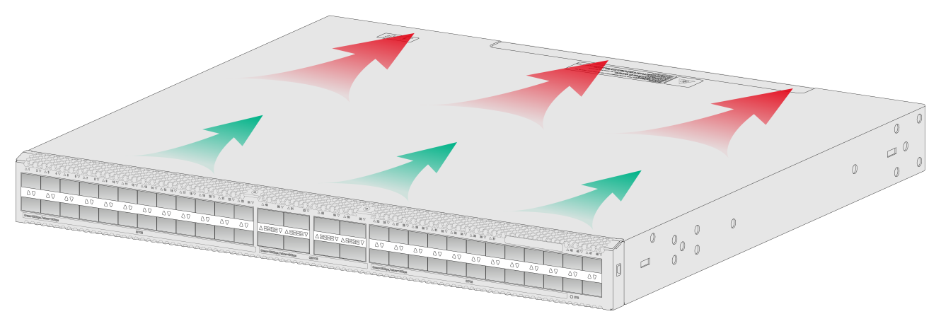
5 Cooling system
To dissipate heat timely and enhance system stability, the switch uses a high-performance cooling system. Consider the site ventilation design when you plan the installation site for the switch.
The switch uses removable fan trays and provides airflow from the port side to the power supply side or from the power supply side to the port side by using different types of fan trays. You must install five fan trays of the same model for the switch. Table5-1 describes the fan trays available for the switch.
Table5-1 Fan trays available for the switch
|
Switch model |
Fan tray model |
Airflow direction |
|
S6530X-48X8C S6530X-48Y8C S6530X-24Y8C S6530X-24X8C S6530X-48X8C-G S6530X-48Y8C-G S6530X-24Y8C-G S6530X-24X8C-G |
LSPM1FANSA-SN |
From the power supply side to the port side |
|
LSPM1FANSB-SN |
From the port side to the power supply side |
Figure5-1 Airflow direction for LSPM1FANSA-SN (S6530X-48Y8C)
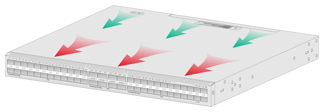
Figure5-2 Airflow direction for LSPM1FANSB-SN (S6530X-48Y8C)