- Table of Contents
- Related Documents
-
| Title | Size | Download |
|---|---|---|
| 02-DetNetOAM configuration | 352.49 KB |
DetNetOAM latency jitter measurement mechanism
Configuring DetNetOAM on an ingress edge node
Configuring DetNetOAM on a transit node or egress edge node
Configuring DetNetOAM probe packets
Binding a DetNet path or path group to a DetNetOAM instance
Configuring the probe interval
Display and maintenance commands for DetNetOAM
DetNetOAM configuration examples
Configuring DetNetOAM
About DetNetOAM
Operations, administration, and maintenance for Deterministic Networking (DetNetOAM) is an active probing technology that ensures deterministic transmission of packets in an SRv6 network. DetNetOAM constructs probe packets simulating the service traffic to detect and calculate the timeslot deviation between adjacent forwarding nodes on the specified DetNet path of the SRv6 network. It then maps the service packets to interface forwarding queues based on the timeslot deviation and works in conjunction with technologies such as network synchronization and DetNet to achieve deterministic transmission of the service packets in the SRv6 network.
Basic DetNetOAM concepts
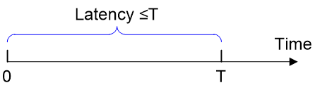
Bounded latency
Bounded latency means having a upper bound T for the latency since a packet is sent from the source end till it is received on the destination end. The latency upper bound T varies by service requirements.
Figure 1 Bounded latency
Bounded jitter
Due to the instability of IP networks, the latency of packets in the same service flow varies, resulting in the latency jitter. Bounded jitter means controlling the latency jitter within an acceptable range. For example, if the latency jitter can be controlled in the range of 0 to Δt , the latency is within the range of [T-Δt/2, T+Δt/2].
Figure 2 Bounded jitter

Deterministic IP networking
Deterministic IP networking is a Layer-3 networking architecture that adopts deterministic IP technology and can implement bounded latency and bounded jitter.
DetNetOAM probe packets
DetNetOAM probe packets are generated by devices for DetNetOAM probing. Devices simulate DetNet flows with upper bound requirements for end-to-end latency and latency jitter and construct probe packets based on the source IP, source port, destination IP, destination port, and DSCP value.
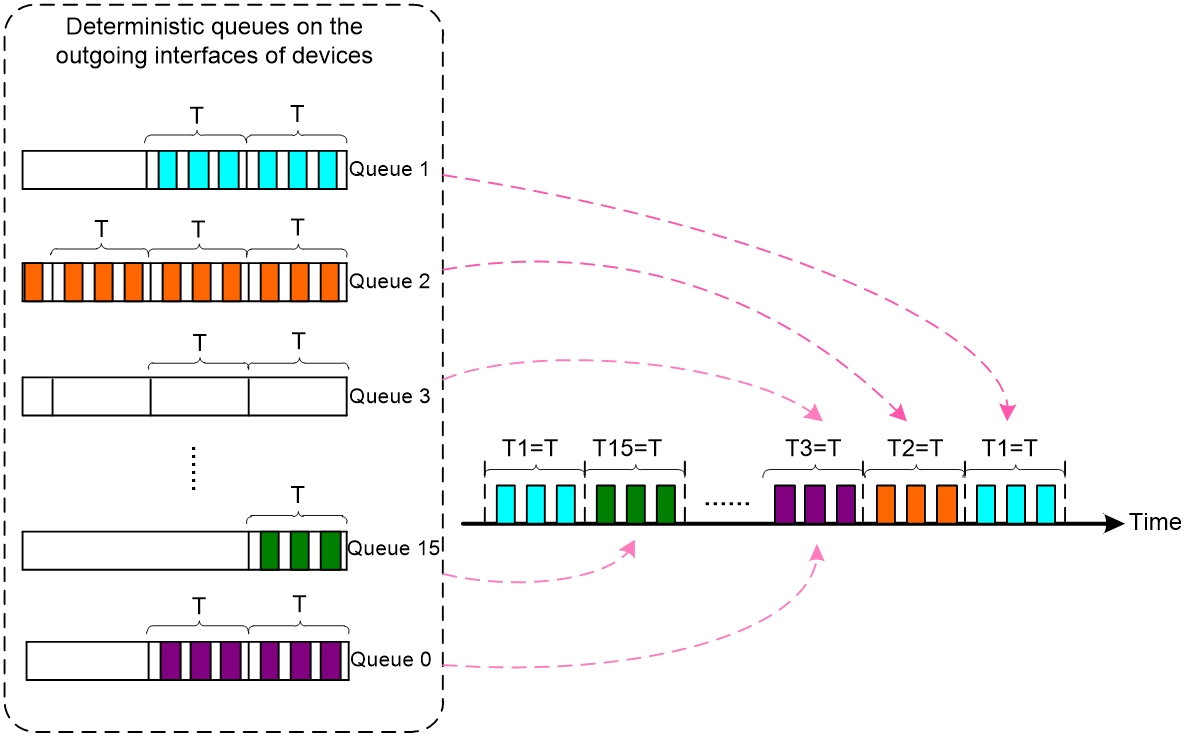
Deterministic queuing
Deterministic queuing is a forwarding mechanism designed to achieve bounded latency and bounded jitter.
The device divides a memory slice on the forwarding chip into 16 queues.
· Queues 1 to 15 are used to forward packets with deterministic transmission requirements.
· Queue 0 is used to forward packets that do not require deterministic transmission.
Each queue take turns to forward packets within its corresponding timeslot (also known as a forwarding cycle). The length of a timeslot is defined in the factory settings. In the current software version, a timeslot is 10 us. If all packets in a queue have been sent before the corresponding timeslot expires, the remaining time in the timeslot will be used to send non-deterministic packets in queue 0. When a timeslot expires, deterministic packets in the next queue will be sent.
As shown in Figure 3, queue 1 corresponds to timeslot T1, queue 2 corresponds to timeslot T2, and so on, with queue 15 corresponding to timeslot T15. Queue 0 is used to send non-deterministic packets. The forwarding chip sends packets in queue 1 to queue 15 in order, with each queue sending packets for a duration of T. As no deterministic packets are sent in queue 3, the device uses the timeslot of queue 3 to send packets from queue 0. After queue 15 sends its packets, queue 1 sends its packets.
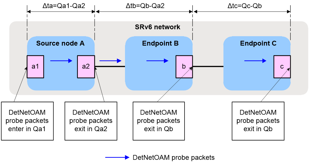
Timeslot deviation
The core function of DetNetOAM is to measure timeslot deviation. Each transit node maps the timeslot deviation to the queues on its output interface to guide packet forwarding.
As shown in Figure 4:
· For an SRv6 source node, DetNetOAM timeslot deviation = incoming queue number for DetNetOAM probe packets to enter the device - outgoing queue number for DetNetOAM probe packets to exit the device.
· For an SRv6 endpoint, DetNetOAM timeslot deviation = outgoing queue number for DetNetOAM probe packets to exit the device - outgoing queue number for DetNetOAM probe packets to exit the upstream device.
Figure 4 DetNetOAM timeslot deviation
Deterministic IP networking
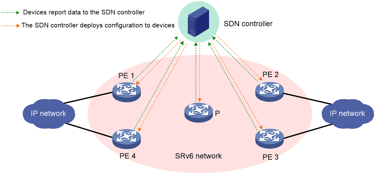
Deterministic IP networking structure
The deterministic IP networking structure mainly includes DetNet devices and the SDN controller, as shown in Figure 5.
· DetNet devices are devices that support DetNet. They will report topology information, bandwidth, latency measurement results, and DetNetOAM probe results to the SDN controller.
· The SDN controller is the control center of the entire deterministic IP network. The controller mainly has the following functions:
¡ Collect network topology and latency information and select paths that meet end-to-end latency requirements for applications.
¡ Collect DetNetOAM probe results and generate a timeslot deviation list in the order based on the position of each device on the SRv6 path.
¡ Summarize the collected results and send them to the source node for route selection and packet encapsulation, thus achieving deterministic forwarding.
Figure 5 Deterministic IP networking structure
Technologies related to deterministic IP networking
The technologies related to deterministic IP networking mainly include:
· PTP and Synchronous Ethernet (SyncE)—To achieve deterministic forwarding and highly precise frequency synchronization between devices, deploy PTP or SyncE in the deterministic IP network. For more information about PTP, see PTP configuration in Network Management and Monitoring Configuration Guide. For more information about SyncE, see network synchronization configuration in Network Management and Monitoring Configuration Guide.
· SRv6—Provides forwarding paths for DetNetOAM probe packets and selects forwarding paths based on SRv6 TE policies. For more information about SRv6, see SRv6 configuration in Segment Routing Configuration Guide. For more information about SRv6 TE policies, see SRv6 TE policy configuration in Segment Routing Configuration Guide.
· DetNet—Controls deterministic IP forwarding, including traffic directing (directing traffic into an SRv6 tunnel), capability set control, and reissuing of timeslot deviation. For more information about DetNet, see DetNet configuration in Deterministic Network Technologies Configuration Guide.
· DetNetOAM—Performs probing for deterministic IP forwarding. After obtaining routing information, DetNetOAM simulates DetNet flows to send probe packets, measures the timeslot deviation between adjacent forwarding devices, and reports the probe results to the controller.
DetNetOAM latency jitter measurement mechanism
Deterministic latency jitter measurement mechanism
Each transit node forwards packets in the timeslot corresponding to the deterministic queue. Unified scheduling is performed for all transit nodes on the path to make sure packets are forwarded within a designated timeslot, thus achieving deterministic transmission of flows in the network.
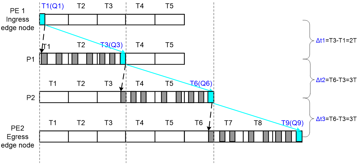
The following example illustrates the design of end-to-end deterministic transmission. As shown in Figure 6, SRv6 selects PE1 -> P1 -> P2 -> PE2 as the forwarding path for a service flow based on latency and bandwidth requirements. Since the path is selected, the latency between nodes on the SRv6 path is deterministic and meets the requirements of the service flow.
1. When the service flow enters the SRv6 network through PE1, PE1 forwards the first packet in queue 1 on its outgoing interface in timeslot T1. Due to network congestion, the service flow might arrive at the downstream node P1 within timeslots T1, T2, or T3. The packets will not arrive at P1 later than T3, because the link is determined and the latency between network nodes is determined when the link bandwidth is not fully occupied. Therefore, the latency jitter of service packets from PE1 to P1 is 0 to 3T, corresponding to a timeslot deviation of 0 to 2T from PE1 to P1.
Use the maximum timeslot deviation of 2T to guide forwarding on P1, which means, the packet sent in queue 1 on PE1 is sent in queue 3 on P1. The first packet arrives at P1 from PE1 is stored on P1 as the first packet in queue 3, waiting to be sent in the queue. The last packet arrives at P1 before T3 expires and can still be sent out as in queue 3 from P1. In this way, all the packets sent out from PE1 in queue 1 are sent out from P1 in queue 3, and the latency jitter of the packets from PE1 to P1 is controlled within 1T.
2. Similarly, packets sent out in queue 3 from P1 might arrive at P2 in T3, T4, T5, or T6, with a slot deviation of 0 to 4T from P1 to P2. Use the maximum slot deviation of 3T to guide forwarding on P2, which means, use queue 6 on P2 to send packets that are sent from P1 in queue 3. In this way, the latency jitter from P1 to P2 can also be controlled within 1T.
3. Similarly, packets sent out from P2 in queue 6 might arrive at PE2 in T6, T7, T8, or T9, with a slot deviation of 0 to 4T from P2 to PE2. Use the maximum slot deviation of 3T to guide forwarding on PE2, which means, use queue 9 on PE2 to send packets that are sent from P2 in queue 6. In this way, the latency jitter from P2 to PE2 can also be controlled within 1T.
As described above, the latency jitter on the egress edge node PE2 is 1T. The latency jitter on the ingress edge node PE1 is also 1T, because a packet might arrive at PE1 at the beginning of T1 or at the end of T1. As a result, end-to-end deterministic transmission technology can control the end-to-end latency jitter within 2T.
Using the maximum timeslot deviation to guide packet forwarding can meet the following requirements:
· The latency jitter of an upstream node on the forwarding path will not affect the latency jitter of the downstream nodes, no matter how many transit nodes are added on the path. The latency jitter on each node will be limited within a timeslot. The latency jitter will not accumulate or spread.
· The egress edge node of a service flow only sends packets within a specific timeslot. In the above example, PE2 sends packets only within T9. The latency jitter on the egress edge node is one timeslot. Plus the latency jitter of one timeslot on the ingress edge node, the deterministic network ultimately controls the end-to-end latency jitter within 2 timeslots.
Figure 6 End-to-end deterministic transmission
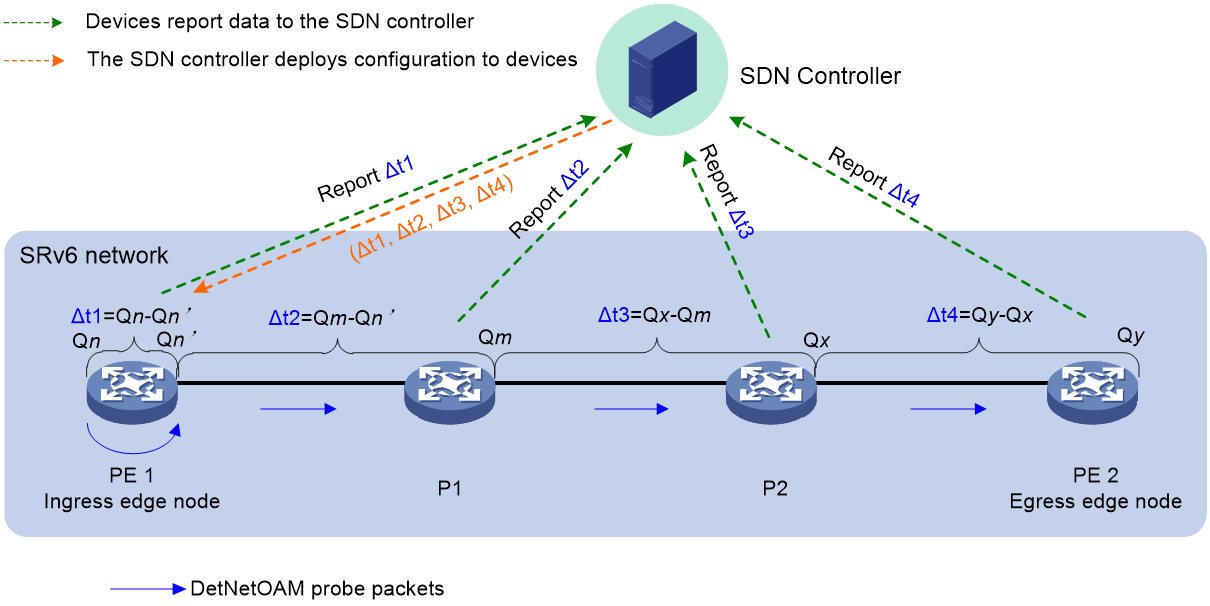
The ingress edge node of an SRv6 path simulates the service flow and constructs DetNetOAM probe packets at the probe interval. The probe interval can be configured by using the period command. Within each interval, DetNetOAM probing is performed for 10 times, and the probe packets are forwarded along the Segment List. Each node on the Segment List calculates the timeslot deviation (Δt1, Δt2, Δt3, and Δt4 in the following figure) between itself and the upstream node, and sends the maximum, minimum, and average values of the timeslot deviation to the controller. The controller takes the maximum value of the timeslot deviation in the probe interval and generates a timeslot deviation list (Δt1, Δt2, Δt3, Δt4) for all nodes on the SRv6 path, and sends the timeslot deviation list to the ingress edge node. The ingress edge node encapsulates the timeslot deviation list in the SRv6 packet header to guide packet forwarding.
DetNetOAM mechanism
Deterministic networking uses the maximum timeslot deviation to guide forwarding and ultimately achieve deterministic latency jitter. DetNetOAM is used to measure the maximum timeslot deviation between adjacent nodes on a forwarding path.
The process of DetNetOAM probing is as follows:
1. The ingress edge node of an SRv6 path simulates the service flow and constructs DetNetOAM probe packets at the configured probe interval. Within each interval, DetNetOAM probing is performed for 10 times, and the probe packets are forwarded along the Segment List.
2. The ingress edge node calculates the timeslot deviation (Δt1 in the following figure) between the incoming interface queue and the outgoing interface queue for probe packets. Each transit node on the Segment List calculates the timeslot deviation (Δt2, Δt3, and Δt4 in the following figure) between itself and the upstream node, and sends the maximum, minimum, and average values of the timeslot deviation to the controller.
3. The controller takes the maximum value of the timeslot deviation in the probe interval and generates a timeslot deviation list (Δt1, Δt2, Δt3, Δt4) for all nodes on the SRv6 path, and sends the timeslot deviation list to the ingress edge node.
4. The ingress edge node encapsulates the timeslot deviation list in the SRv6 packet header to guide packet forwarding.
DetNetOAM probing process
As shown in Figure 8, DetNetOAM probing is performed as follows:
1. On the ingress edge node PE1:
a. The ingress edge node generates DetNetOAM probe packets based on the characteristics of the service flow to simulate the service flow.
b. DetNetOAM probe packets enter the device through the specified incoming interface (which can be configured through the CLI) in a random queue assumed to be Qn.
c. The ingress edge node forwards DetNetOAM probe packets along the specified SRv6 path (which can be configured through the CLI). The probe packets exit in a random queue assumed to be Qn’.
d. The ingress edge node calculates the timeslot deviation Δt1 calculated as Qn’ minus Qn.
e. The ingress edge node encapsulates the outgoing interface queue number Qn’ into DetNetOAM probe packets and sends them to the next node P1.
2. On P1:
a. P1 matches DetNetOAM probe packets based on the configured flow characteristics.
b. P1 decapsulates the DetNetOAM probe packets and obtains the outgoing interface queue Qn’ of the upstream node. Then, it forwards the DetNetOAM probe packets following the SRv6 forwarding process in a random queue assumed to be Qm.
c. P1 calculate the timeslot deviation Δt2 = Qm-Qn’.
d. P1 encapsulates its outgoing interface queue number Qm into the DetNetOAM probe packets and sends them to the next node P2.
3. P2 and PE2 process DetNetOAM probe packets in the same way as P1 does.
As the egress edge node, PE2 reports the DetNetOAM probe results to the controller, and then discards the DetNetOAM probe packets.
4. To simulate service packets and provide accurate probe results, the ingress edge node performs DetNetOAM probing at the specified probe interval. The ingress edge node generates 10 DetNetOAM probe packets and performs DetNetOAM probing for 10 times within each probe interval.
All nodes forward each DetNetOAM probe packet in the same way as a service packet is forwarded and obtains the timeslot deviation. Based on the probe results of 10 probe packets, each node calculates the minimum, maximum, and average values of the timeslot deviation for the node within a probe interval, and reports the timeslot deviation values, interval ID, and node index on the SRv6 path to the controller with Telemetry packets.
The controller generates a timeslot deviation list for nodes in the order specified in the Segment List based on the received probe results, and send the timeslot deviation list to the ingress edge node. The ingress edge node uses the timeslot offset list issued by the controller to calculate the outgoing queue for service packets on each node and guide packet forwarding.
DetNetOAM probing process
Figure 8 SRv6 packet forwarding based on DetNetOAM probe results
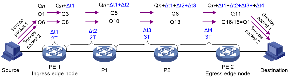
As shown in Figure 8, DetNetOAM probing obtains a maximum timeslot deviation of 2T on the ingress edge node and from PE1 to P1, and a maximum timeslot deviation of 3T from P1 to P2 and from P2 to PE2. The controller issues a timeslot deviation list (2T, 2T, 3T, 3T) to the ingress edge node. Service packets of the deterministic network are forwarded as follows:
1. The administrator completes the configuration of SRv6, SRv6 TE policy, DetNet, and DetNetOAM.
2. The SRv6 TE policy selects an optimal path and use it as the forwarding path for the service packets.
3. The ingress edge node receives a service packet and looks up the routing table based on the destination address to perform SRv6 forwarding using the optimal path.
4. If service packet 1 enters the SRv6 network in queue Q1 of the ingress edge node PE1.
a. According to the timeslot deviation list (2T, 2T, 3T, 3T), PE1 calculates queues Q3, Q5, Q8, and Q11 for the packet to exit PE1, P1, P2, and PE2, respectively.
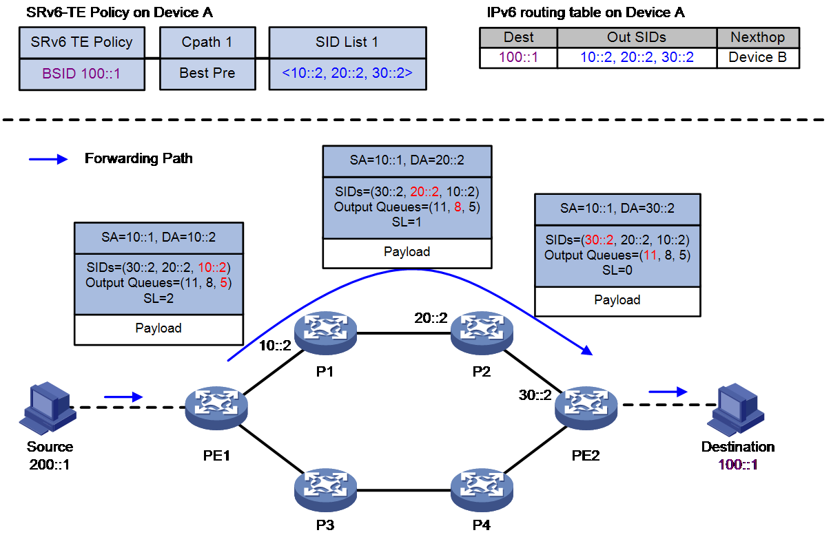
b. PE1 generates the outgoing queue list corresponding to the Segment List (11, 8, 5) and encapsulates the outgoing queue list in the SRv6 packet header of the service packet, as shown in Figure 9.
c. PE1 puts the service packet in queue Q3 for sending it to P1.
5. P1 obtains the queue number for the service packet to exit P1 from the SRv6 packet header and puts the packet in queue Q5 for sending it to P2, as shown in Figure 9.
6. P2 obtains the queue number for the service packet to exit P2 from the SRv6 packet header and puts the packet in queue Q8 for sending it to PE2, as shown in Figure 9.
7. PE2 obtains the queue number for the service packet to exit PE2 from the SRv6 packet header and puts the packet in queue Q11 for sending it to the destination end, as shown in Figure 9.
If service packet 2 enters the SRv6 network in queue Q6 of the ingress edge node PE1, according to the timeslot deviation list (2T, 2T, 3T, 3T), the queues for the packet to exit PE1, P1, P2, and PE2 are Q8, Q10, Q13, and Q1, respectively. A total of 15 deterministic queues exist, thus the queue 3 timeslots after Q13 is Q1.
Figure 9 Srv6 packet encapsulation and forwarding in the DetNet network
DetNetOAM tasks at a glance
Configuring DetNetOAM on an ingress edge node
To configure DetNetOAM on an ingress edge node, perform the following tasks:
2. Creating a DetNetOAM instance
3. Configuring DetNetOAM probe packets
4. Binding a DetNet path or path group to a DetNetOAM instance
5. Configuring the probe interval
Configuring DetNetOAM on a transit node or egress edge node
To configure DetNetOAM on an ingress edge node, perform the following tasks:
Enabling DetNetOAM
1. Enter system view.
system-view
2. Enable DetNetOAM and enter DetNetOAM view. If DetNetOAM has been enabled, enter DetNetOAM view.
detnetoam enable
By default, DetNetOAM is disabled.
Creating a DetNetOAM instance
About this task
A DetNetOAM instance can provide DetNetOAM probing services for only one DetNet flow. To perform DetNetOAM probing for multiple SRv6 DetNet flows, configure multiple DetNetOAM instances on the device as needed.
Procedure
system-view
2. Enter DetNetOAM view.
detnetoam enable
3. Create a DetNetOAM instance and enter its view.
instance instance-name
Configuring DetNetOAM probe packets
About this task
Perform this task to configure parameters for DetNetOAM probe packets. The device constructs DetNetOAM probe packets based on these parameters. As a best practice, configure these parameters according to the parameters of the DetNet flow to be probed. For more information about parameters of DetNet flows, see DetNet configuration in Deterministic Network Technologies Configuration Guide.
Procedure
1. Enter system view.
system-view
2. Enter DetNetOAM view.
detnetoam enable
3. Enter DetNetOAM instance view.
instance instance-name
4. Configure parameters for DetNetOAM probe packets.
IPv4:
flow source-ip src-ip-address destination-ip dest-ip-address source-port src-port-number destination-port dest-port-number [ dscp dscp-value ]
IPv6:
flow source-ipv6 src-ipv6-address destination-ipv6 dest-ipv6-address source-port src-port-number destination-port dest-port-number [ dscp dscp-value ]
By default, no parameters are configured for DetNetOAM probe packets.
If you configure this command multiple times for a DetNetOAM instance, the most recent configuration takes effect.
5. Set the payload size for each probe packet.
data-size size
By default, the payload size is 128 bytes.
Binding a DetNet path or path group to a DetNetOAM instance
About this task
Perform this task to bind an SRv6 path that is used for transmitting a DetNet flow to a DetNetOAM instance.
After you bind an SRv6 path to the DetNetOAM instance, DetNetOAM probing will be performed along the bound path.
Prerequisites
Before performing this task, first configure a DetNet path. For more information about DetNet paths, see DetNet configuration in Deterministic Network Technologies Configuration Guide.
Procedure
1. Enter system view.
system-view
2. Enter DetNetOAM view.
detnetoam enable
3. Enter DetNetOAM instance view.
instance instance-name
4. Bind a DetNet path.
binding-path-id path-id
By default, no path or path group is bound to a DetNetOAM instance.
Configuring the probe interval
About this task
Perform this task to configure the DetNetOAM probe interval. DetNetOAM performs probing according to the probe interval, and updates the timeslot deviation list based on the probing results. This enable devices to adapt to the dynamic changes in the network and achieve deterministic forwarding.
Procedure
1. Enter system view.
system-view
2. Enter DetNetOAM view.
detnetoam enable
3. Enter DetNetOAM instance view.
instance instance-name
4. Configure the probe interval for the DetNetOAM instance.
period period
By default, the probe interval for a DetNetOAM instance is 60 seconds.
Enabling DetNetOAM probing
1. Enter system view.
system-view
2. Enter DetNetOAM view.
detnetoam enable
3. Enter DetNetOAM instance view.
instance instance-name
4. Enable DetNetOAM probing for the DetNetOAM instance.
measure enable
By default, DetNetOAM probing is disabled for a DetNetOAM instance.
Display and maintenance commands for DetNetOAM
Execute display commands in any view.
Table 1 Display and maintenance commands for DetNetOAM
|
Task |
Command |
|
Display DetNetOAM instance information. |
display detnetoam instance [ instance-name ] |
|
Display DetNetOAM probing results in the most recent five probe intervals. |
display detnetoam statistic [ path-id path-id path-hop path-hop ] |
DetNetOAM configuration examples
Example: Configuring DetNetOAM to measure the timeslot deviation for a single path in an SRv6 TE policy network
Network configuration
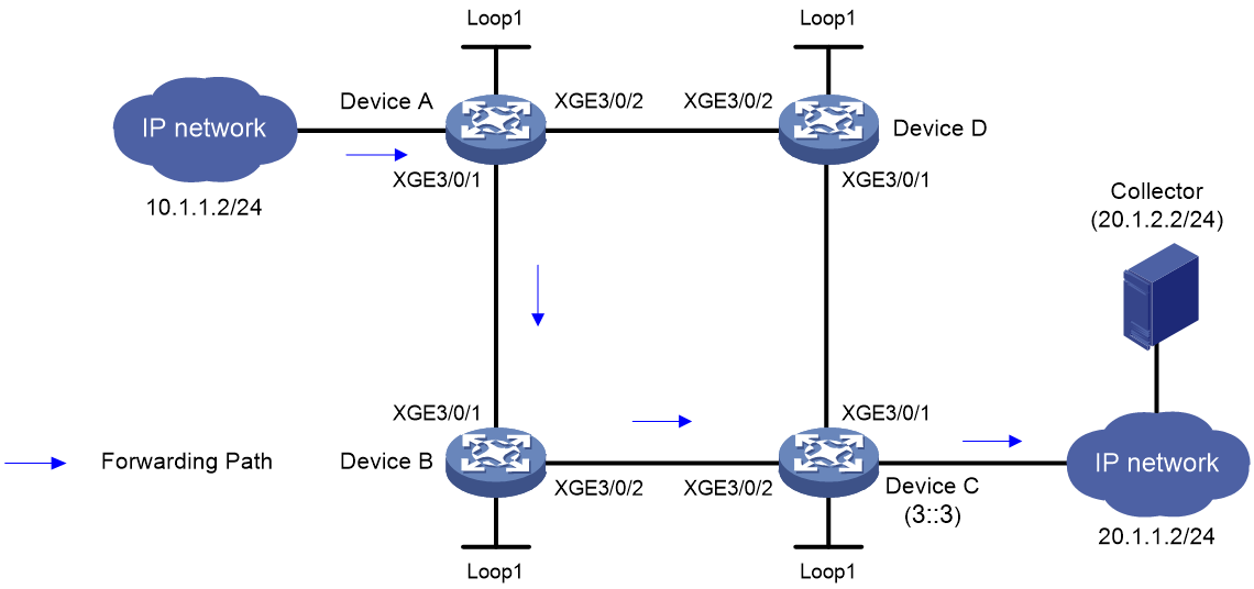
As shown in Figure 10, an SRv6 TE policy is deployed in the IGP network. Perform the following tasks to specify that the service traffic is forwarded sequentially through Device A, Device B, Device C, and Device D:
· Configure IS-IS for Device A to Device D to achieve Layer 3 connectivity.
· Configure an SRv6 TE policy on Device A to specify the forwarding path as Device A -> Device B -> Device C -> Device D.
· Configure DetNetOAM to measure the timeslot deviation between adjacent devices on the forwarding path, and report the timeslot deviation to the controller through gRPC to provide deterministic forwarding services for packets on the path.
Network diagram
Figure 10 Configuring DetNetOAM in an SRv6 TE policy network
Prerequisites
Set up an SRv6 TE policy network. (Details not shown.) For the detailed configuration procedures, see SRv6 TE policy configuration in Segment Routing Configuration Guide.
Configuring Device A
1. Configure gRPC:
# Enable the gRPC service.
<DeviceA> system-view
[DeviceA] grpc enable
# Create sensor group test and configure sensor path detnetoam/measurereports.
[DeviceA] telemetry
[DeviceA-telemetry] sensor-group test
[DeviceA-telemetry-sensor-group-test] sensor path detnetoam/measurereports
[DeviceA-telemetry-sensor-group-test] quit
# Create destination group collector1, and add an IPv4 collector with IP address 20.1.2.2 and port number 50051 to the destination group.
[DeviceA-telemetry] destination-group collector1
[DeviceA-telemetry-destination-group-collector1] ipv4-address 20.1.2.2 port 50051
[DeviceA-telemetry-destination-group-collector1] quit
# Configure subscription A to bind sensor group test with destination group collector1. Set the data collection interval to 20 seconds.
[DeviceA-telemetry] subscription A
[DeviceA-telemetry-subscription-A] sensor-group test sample-interval 20
[DeviceA-telemetry-subscription-A] destination-group collector1
[DeviceA-telemetry-subscription-A] quit
[DeviceA-telemetry] quit
2. # Switch the subcard operating mode to DetNet mode.
[DeviceA] subslot-working-mode slot 18 subslot 1 detnet
Change of the subslot working mode will reboot the subcard. Continue? [Y/N]y
3. Configure DetNet:
# Configure parameters for a DetNet flow.
[DeviceA] detnetip flow 1 source-ip 10.1.1.2 mask 24 destination-ip 20.1.1.2 mask 24 source-port 1000 destination-port 1000
# Configuring a DetNet path.
[DeviceA] detnetip path 1
[DeviceA-detnet-path1] source interface ten-gigabitethernet 3/0/1
[DeviceA-detnet-path1] apply flow 1
[DeviceA-detnet-path1] type srv6
[DeviceA-detnet-path1-srv6] policy color 1 end-point ipv6 3::3
[DeviceA-detnet-path1-srv6] quit
[DeviceA-detnet-path1] quit
4. Configure DetNetOAM:
# Enable DetNetOAM.
[DeviceA] detnetoam enable
# Create DetNetOAM instance a and configure parameters for DetNetOAM probe packets.
[DeviceA-detnetoam] instance a
[DeviceA-detnetoam-instance-a] flow source-ip 10.1.1.2 destination-ip 20.1.1.2 source-port 1000 destination-port 1000
# Bind DetNet path 1 to DetNetOAM instance a.
[DeviceA-detnetoam-instance-a] binding-path-id 1
# Set the probe interval to 10 seconds.
[DeviceA-detnetoam-instance-a] period 10
# Enable DetNetOAM probing.
[DeviceA-detnetoam-instance-a] measure enable
[DeviceA-detnetoam-instance-a] quit
[DeviceA-detnetoam] quit
Configuring Device B
1. Configure gRPC:
Configure gPRC on Device B in the same way as Device A is configured.
2. # Switch the subcard operating mode to DetNet mode.
<DeviceB> system-view
[DeviceB] subslot-working-mode slot 18 subslot 1 detnet
Change of the subslot working mode will reboot the subcard. Continue? [Y/N]y
3. Enable DetNetOAM probing.
[DeviceB] detnetoam enable
[DeviceB-detnetoam] quit
Configuring Device C
1. Configure gRPC:
Configure gPRC on Device B in the same way as Device A is configured.
2. # Switch the subcard operating mode to DetNet mode.
<DeviceC> system-view
[DeviceC] subslot-working-mode slot 18 subslot 1 detnet
Change of the subslot working mode will reboot the subcard. Continue? [Y/N]y
3. Enable DetNetOAM probing.
[DeviceC] detnetoam enable
[DeviceC-detnetoam] quit
Verifying the configuration
1. Display DetNetOAM probing results on Device A.
[DeviceA] display detnetoam statistics
PathID: 1 PathHop: 1
Period ID TimeSlotMax TimeSlotMin TimeSlotAvg
166609117 1 0 0
166609118 0 0 0
166609119 1 0 0
166609120 0 0 0
166609121 0 0 0
2. Display DetNetOAM probing results on Device B.
[DeviceB] display detnetoam statistics
PathID: 1 PathHop: 2
Period ID TimeSlotMax TimeSlotMin TimeSlotAvg
166609117 1 0 0
166609118 1 0 0
166609119 1 0 0
166609120 1 0 0
166609121 1 0 0
3. Display DetNetOAM probing results on Device C.
[ DeviceC] display detnetoam statistics
PathID: 1 PathHop: 3
Period ID TimeSlotMax TimeSlotMin TimeSlotAvg
166609117 1 0 0
166609118 1 0 0
166609119 1 0 0
166609120 1 0 0
166609121 1 0 0
