- Table of Contents
- Related Documents
-
| Title | Size | Download |
|---|---|---|
| 01-DetNet configuration | 252.43 KB |
Deterministic network overview
DetNet end-to-end network architecture
Mechanisms to achieve DetNet QoS
End-to-end deterministic transmission mechanism of RCQF
DetNet forwarding process overview
Restrictions: Hardware compatibility with DetNet
Configuring SRv6 path policy attributes for a DetNet path
Specifying the source interface for a DetNet path
Applying a DetNet path to a DetNet flow for forwarding
Configuring a forwarding timeslot for a DetNet path
Display and maintenance commands for DetNet
Example: Configuring DetNet in an SRv6 TE policy network
Configuring DetNet
About DetNet
Deterministic Networking (DetNet) is a new type of IP network technology that provides deterministic transmission services for IP flows with high real-time requirements, ensuring ultra-low packet loss ratio and bounded end-to-end latency and jitter.
Based on the IETF DetNet standard, H3C proposes an end-to-end deterministic data transmission solution built upon Resilient Cycle Queuing and Forwarding (RCQF).
RCQF is an extension of Cycle Queuing and Forwarding (CQF). RCQF focuses on meeting the low jitter requirement in end-to-end deterministic transmission, and increases the flexibility to make it suitable for wide area networks. It is capable of adapting to various scenarios in terms of the latency, jitter, high bandwidth, large packet length, interface rate, and scenarios only requiring frequency synchronization.
Deterministic network overview
Technical background
Traditional Ethernet transmits data in a best-effort manner, which can only reduce end-to-end latency to tens of milliseconds. However, many emerging applications, such as smart driving, vehicle-to-vehicle communication, smart transportation, industrial control, smart agriculture, remote surgery, autonomous driving, VR games, and other smart services, require end-to-end latency control within several milliseconds, latency jitter control within one millisecond, and reliability control above 99.9999%. Therefore, a new generation network that can provide timely and accurate data transmission is urgently needed.
DetNet is a technology that provides assured service quality for multiple services on top of Ethernet.
Deterministic quality of service (QoS) can provide timely and accurate data transmission service quality. Typical deterministic QoS includes: low latency (upper limit determined), low jitter (upper limit determined), low packet loss ratio (upper limit determined), high bandwidth (upper and lower limits determined).
DetNet aims to build large-scale networks and provide assured QoS. It offers real-time, high-quality, and reliable data transmission services for agriculture, industry, and service sectors, and facilitates the transformation towards high-quality development.
Deterministic network technologies
Deterministic network technologies aim to achieve assured latency, jitter, packet loss ratio, bandwidth, and reliability.
Deterministic network technologies mainly includes:
· Flexible Ethernet (FlexE)—Implements deterministic bandwidth assurance.
· Time-sensitive networking (TSN)—Implements deterministic assurance at the link layer.
· Deterministic networking (DetNet)—Implements deterministic assurance at the network layer.
· Deterministic IP (DIP)—Implements end-to-end deterministic assurance for IP networks.
· Deterministic WiFi (DetWiFi)—Implements deterministic transmission in wireless local area networks.
· 5G deterministic networking (5GDN)—Implements deterministic and differentiated services for 5G networks.
DetNet technology background
With the development of the industrial Internet and the rapid deployment and upgrade of 5G vertical industries (including the Internet, manufacturing, transportation, energy and power, health care, education sectors), a large number of intelligent machines will be involved in networks. Machine-oriented communication will generate many new network functional requirements. The transformation of network service objects and service models has made the assumption that high bandwidth lead to high quality no longer universally applicable. Timely and deterministic data transmission at the network layer has become one of the key requirements for future networks.
The existing IP network cannot provide deterministic end-to-end packet forwarding while supporting massive connections due to its best-effort forwarding mechanism and the presence of microbursts and congestion.
· Connectionless statistical time division multiplexing network: The IP network is a connectionless statistical time division multiplexing network, where packets from different incoming interfaces are sent out based on their arrival time at the output interface queue. Each packet has an equal chance of being scheduled in the output interface queue, which implements efficient utilization of network bandwidth. However, the bandwidth used by the packets is uncertain, which increases the uncertainty of packet forwarding latency.
· Bursty service packets: Various types of service packets need to be carried in the IP network. In live networks, most of the service packets are not sent regularly, which leads to conflicts when multiple service packets are sent at the same time on an outgoing interface. Latency becomes larger as the the conflict of packet transmission becomes more severe and the number of forwarding nodes increases.
· Various latency requirements for industrial Internet services: In the industrial Internet, different service scenarios have different latency requirements. In some remote control scenarios, the network is required to implement ultra-low end-to-end latency and highly accurate jitter control. For example, a servo motor sends control commands with an interval of 250 us. When the network jitter exceeds 250 us, the issue of asynchronous movement between the active robotic arm and the passive robotic arm will occur.
· 5G network access has promoted the latency requirements for various service scenarios: With the rapid development of 5G, the digitalization process in various industries will also advance rapidly. Different industries have different service scenarios, and different scenarios have different requirements for the determinism of forwarding latency. Some service scenarios have higher requirements for the determinism of forwarding latency. For example, the power industry requires a latency of less than 5ms and a jitter of less than 200us for data communication between devices.
DetNet is proposed to provide deterministic transport capability on top of the existing IP network and meet the deterministic requirements of the industrial Internet and 5G vertical industries.
The IETF established the DetNet working group in October 2015. This working group focuses on implementing deterministic data paths on the IP network, which can provide deterministic latency, jitter, zero packet loss, and high reliability for Layer 3 data. DetNet can meet the requirements of professional audio/video, in-vehicle multimedia systems, industrial control systems, smart building automation systems, power and telecommunication systems, and other application domains.
DetNet end-to-end network architecture
H3C DetNet end-to-end network architecture, as shown in Figure 1, includes end systems, SDN controller, and DetNet nodes. Based on different positions on the forwarding plane, DetNet nodes can be divided into three categories: ingress edge nodes, transit nodes, and egress edge nodes.
Figure 1 DetNet end-to-end network architecture
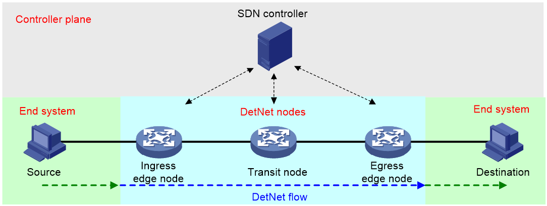
· SDN controller—Collects information including the topology and latency of the DetNet network, calculates the paths that meet the end-to-end latency requirements of the service, and establishes a mapping relationship between DetNet flows and forwarding cycles.
· Ingress edge node—Based on packet characteristics, determines whether a flow between end systems is allowed to enter the DetNet network for deterministic forwarding, and divides the packets that arrive irregularly into different forwarding cycles. The flow entering the DetNet network is called a DetNet flow, which can be defined by the five-tuple of IP packets (source IP address, destination IP address, source port number, destination port number, protocol type) and the DSCP value.
· Transit node and egress edge node—Forwards the incoming packets through its outgoing interface in the timeslot for the corresponding queue
Mechanisms to achieve DetNet QoS
DetNet provides deterministic latency, jitter, zero packet loss, and high reliability for Layer 3 networks through the following mechanisms:
· Congestion protection.
Packet loss issues occur mainly due to congestion in best-effort networks. DetNet achieves ultra-low latency and zero congestion loss through the division of forwarding timeslots, resource reservation (including link bandwidth reservation, node buffer reservation), and packet preemption. DetNet also implement lower latency jitter by controlling the end-to-end latency between the upper and lower limits.
· Reliable delivery.
Another important reason for packet loss in best-effort networks is device or link failure. DetNet ensures reliable delivery of DetNet flows through packet replication and elimination. The ingress edge node sends multiple copies of DetNet flows through multiple paths with packet replication and encoding. Each replicated packet is forwarded to or near its destination. The egress edge node eliminates redundant copies restores the original packets through packet elimination, packet ordering, and data decoding. In this way, DetNet avoids packet loss caused by single-point failures on the path.
· Explicit Routes.
In order to eliminate the impact of protocol convergence time and maintain the stability of forwarding paths, DetNet calculates the optimal path for DetNet flows through specific protocols or centralized control units and uses redundant paths to ensure uninterrupted services in case of individual link failures.
· Elastic scheduling.
DetNet enforces the differentiation of bandwidth resources between DetNet and non-DetNet flows. To maintain high bandwidth usage, DetNet allows the scheduling of idle resources from DetNet flows to non-DetNet flows within each scheduling cycle. The elastic scheduling mechanism of DetNet achieves seamless adjustment between DetNet and non-DetNet resources.
These mechanisms can be applied independently or in combination. Using them in combination can provide the maximum QoS assurance for services with low latency requirements.
End-to-end deterministic transmission mechanism of RCQF
To ensure deterministic latency and jitter in end-to-end transmission, RCQF adopts a cyclic queuing and forwarding mechanism. Each deterministic traffic flow are assigned with a forwarding cycle. In this way, RCQF controls the behavior of each flow to avoid conflicts, reduces queuing latency within nodes, and ultimately achieves deterministic latency.
Figure 2 Queuing and forwarding for end-to-end deterministic transmission
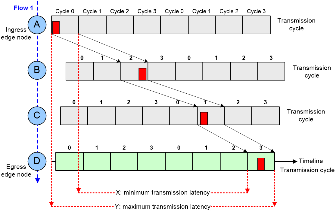
The queuing and forwarding for end-to-end deterministic transmission is implemented as follows:
1. The forwarding path and timing for each deterministic flow is planned. For example, for Flow 1 in Figure 2, the planned forwarding path is node A -> node B -> node C -> node D.
2. All nodes on the packet forwarding path perform accurate frequency synchronization. Then, the timelines on the nodes are divided into equal cycles (with a duration of T).
3. Every pair of adjacent nodes establish a stable cyclic mapping relationship. Then, the controller plane of the DetNet network uniformly schedules the deterministic flows to make sure they are forwarded only within a specific timeslot. For example, a packet sent in cycle 0 from node A will be sent in cycle 2 from node B, as shown in Figure 2. For each pair of adjacent nodes, the difference in the cycle number for each deterministic flow remains fixed, but the exact time at which a packet is sent within the corresponding cycle might vary.
4. All nodes along the path cache, encapsulate, and periodically forward packets of deterministic flows along the predetermined forwarding path based on the established cyclic mapping relationships
In this way, the sending time of a packet at each node on the forwarding path is limited within a specific cycle, and the latency jitter of the packet at that node is bounded. No matter how many nodes exist on the path, the jitter of the previous node will not increase the jitter latency of the subsequent node, but only increase the overall latency of the packet. Each node absorbs the corresponding jitter in time, preventing the overall jitter from accumulating or spreading and ensuring an end-to-end jitter of two cycles (Y-X=2T).
· The minimum transmission latency (X) occurs when the first node sends a packet at the end of a cycle, and the last node sends the packet at the beginning of a cycle.
· The maximum transmission latency (Y) occurs when the first node sends a packet at the beginning of a cycle, and the last node sends the packet at the end of a cycle.
RCQF key features
Accurate frequency synchronization
Highly accurate frequency synchronization is the foundation for deterministic forwarding path measurement and calibration. Deterministic forwarding path requires all forwarding network elements to be based on the same time identifier. Each forwarding network element selects the timing for packet forwarding based on a globally unified time, thus implementing deterministic latency and jitter.
In a DetNet network, after a required clock source is specified, all devices adopt technologies such as Precision Time Protocol (PTP) and Synchronous Ethernet (SyncE) to achieve nanosecond-level frequency synchronization. For more information about PTP, see PTP configuration in Network Management and Monitoring Configuration Guide. For more information about SyncE, see network synchronization configuration in Network Management and Monitoring Configuration Guide.
Measurement and calibration
In a DetNet network, each node on the DetNet path uses technologies such as DetNetOAM to accurately measure the latency and jitter within each node and between uplink and downlink nodes. The measurement results are reported to the SDN controller, which calculates the precise cyclic mapping relationships between nodes and sends the mapping information to the ingress edge node.
The ingress edge node maps different DetNet flows to different interface queues based on the received cyclic mapping information, and identifies the queue mapping information of the path in the packet headers to guide subsequent nodes in forwarding.
For more information about DetNetOAM, see DetNet Configuration Guide.
Deterministic collaboration
Before a DetNet flow is forwarded, the DetNet system plans the DetNet path and reserve all resources along the path for the flow. This process requires collaboration between the SDN controller and DetNet nodes. The process of deterministic collaboration includes the following key steps:
1. Information collection: The SDN controller collects the global topology and device capability information (including the interfaces supporting DetNet, interface bandwidth, number of queues on the interfaces) in the DetNet network, and maintains real-time monitoring of information about the corresponding paths, interfaces, bandwidth, and queues.
2. Service deployment: Configure DetNet forwarding policies for specified DetNet flows on the SDN controller, specifying the network ingress, network egress, DetNet QoS requirements.
3. Explicit route planning: The SDN controller combines collected path status information and measurement to dynamically calculate whether a path exists in the network that meets the requirements, including end-to-end latency and jitter requirements, and whether the remaining bandwidth of each device interface is sufficient. If a path meets the conditions, the SDN controller will plan the corresponding SRv6 explicit route for the DetNet flow. For more information about SRv6, see SRv6 configuration and SRv6 TE policy configuration in Segment Routing Configuration Guide.
4. DetNet configuration issuing: The SDN controller delivers the DetNet flow characteristics, cyclic mapping information, and SRv6 explicit route information to the ingress edge node. After the DetNet flow enters the network, it will be forwarded along the specified path starting from the ingress edge node.
Cyclic mapping
Cycle mapping ensures that multiple data packets of a DetNet flow will be sent from each node within the specified cycle.
1. Equal cycle partitioning: To avoid microbursts caused by statistical time division multiplexing forwarding, it is necessary to control the forwarding behavior of each packet at each hop. It is difficult to limit the time when a packet enters and exits a device to an exact moment, but it is relatively easy to control it within a time period. Therefore, each node can divide its timeline into equal time period of T as the cycle and arrange the cycle for receiving and sending each packet.
2. Edge shaping: The ingress edge node maps packets of different DetNet flows to different interface forwarding queues based on pre-issued flow characteristics and cyclic mapping information. It also adds the cyclic mapping information of the path into the SID list of the SRv6 packet headers.
3. Queue mapping: Each transit node schedules all packets of a DetNet flow received within a cycle from the uplink node based on the cyclic mapping relationships carried in the packets, and forwards them within the specified cycle of the node. Finally, packets are sent from the egress edge node.
Deterministic scheduling
The timeline on each DetNet node is divided into the millisecond-level equal-length cycles. Each DetNet node performs strict cyclic scheduling for DetNet flows, ensuring that each packet is queued and forwarded within the specified cycle.
In a cycle, only the corresponding queue will be opened, and the packets in the queue will be sent. Other queues are closed and can only receive packets.
DetNet forwarding process overview
Figure 3 shows the overall forwarding process of a DetNet flow in a DetNet network.
Figure 3 DetNet forwarding process
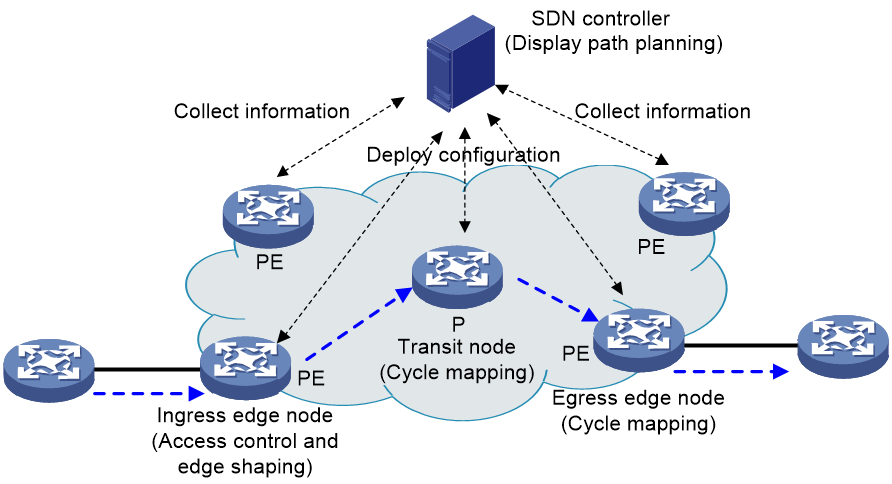
1. In a DetNet network, all devices adopt technologies such as PTP and SyncE to achieve nanosecond-level frequency synchronization.
2. Each node measures the latency and jitter within a single node and between the uplink and downlink nodes accurately through technologies such as DetNetOAM.
3. The SDN controller calculates the SRv6 explicit routes and queue mapping information that meet the DetNet requirement for latency based on the configured policies, and then issues the information to the ingress edge node. For networks that do not support SDN controllers, DetNet flows and DetNet paths can be manually configured on the ingress edge node.
4. The ingress edge node identifies and filters packets incoming through a specified interface based on flow characteristics. It then encapsulates the packets with SRv6, and appends the SID list with the cycle attributes of each transit node in the SRH header. When DetNet flows exceed the reserved bandwidth of the interface, the ingress edge node discards packets that exceed the bandwidth and does not provide deterministic transmission assurance.
5. The encapsulated data packets are shaped on the ingress edge node, enter the corresponding queue and are forwarded within the specified cycle.
6. When the data packets arrive enters a downlink node, the node puts the packets in the corresponding queue based on the cycle attributes carried in the packet headers, and then waits for cyclic scheduling and forwarding.
Significance of DetNet
Promoting the development of the industrial Internet
DetNet networks implement deterministic forwarding with bounded jitter and bounded latency. This not only ensures timely and accurate control of industrial control services in current production networks, but also provides microsecond-level latency and jitter assurance for future industrial automation, industrial teleoperation, holographic communication, vehicle-road coordination, and other services, promoting smart manufacturing and industrial digitization.
Accelerating industry upgrades
DetNet networks can meet differentiated requirements for latency and jitter in various industry scenarios. The large-scale deployment of DetNet and other new technologies, such as SDN/NFV, big data, and artificial intelligence, will makes networks flexible, secure, and reliable. This will integrate wired and wireless networks, IT/OT convergence, and provide multidimensionally visual, secure, reliable, and intelligent network services. It can accelerate comprehensive industrial upgrades in manufacturing, logistics, transportation, film and television, health care, agriculture and animal husbandry, and service sectors.
Restrictions: Hardware compatibility with DetNet
Only MIC-CQ1LF-M and MIC-XP10L-M interface modules support this feature.
In SRv6 networks, only SRv6 TE supports DetNet. Do not deploy DetNet in SRv6 BE scenarios, because SRv6 BE does not support DetNet.
Protocols and standards
· RFC 8557: Deterministic Networking Problem Statement
· RFC 8578: Deterministic Networking Use Cases
· RFC 8655: Deterministic Networking Architecture
· RFC 8938: Deterministic Networking (DetNet) Data Plane Framework
· RFC 8939: Deterministic Networking (DetNet) Data Plane: IP
· RFC 8964: Deterministic Networking (DetNet) Data Plane: MPLS
· RFC 9016: Flow and Service Information Model for Deterministic Networking (DetNet)
· RFC 9023: Deterministic Networking (DetNet) Data Plane: IP over IEEE 802.1 Time-Sensitive Networking (TSN)
· RFC 9024: Deterministic Networking (DetNet) Data Plane: IEEE 802.1 Time-Sensitive Networking over MPLS
· RFC 9025: Deterministic Networking (DetNet) Data Plane: MPLS over UDP/IP
· RFC 9037: Deterministic Networking (DetNet) Data Plane: MPLS over IEEE 802.1 Time-Sensitive Networking (TSN)
· RFC 9055: Deterministic Networking (DetNet) Security Considerations
· RFC 9056: Deterministic Networking (DetNet) Data Plane: IP over MPLS
DetNet tasks at a glance
To configure DetNet in a network not supporting the SDN controller, perform the following tasks on the ingress edge node:
b. Configuring SRv6 path policy attributes for a DetNet path
c. Specifying the source interface for a DetNet path
d. Applying a DetNet path to a DetNet flow for forwarding
e. Configuring a forwarding timeslot for a DetNet path
Prerequisites for DetNet
As a best practice, configure DetNetOAM to obtain timely packet forwarding timeslot information for subsequent DetNet configuration. For more information about DetNetOAM, see DetNetOAM configuration in DetNet Configuration Guide.
Make sure the corresponding SRv6 TE policy exists on the ingress edge node of the specified DetNet path, and the transmit nodes support SRv6 forwarding. For more information about SRv6 TE policies, see SRv6 TE policy configuration in Segment Routing Configuration Guide.
DetNet requires high-performance hardware support. When configure the SRv6 TE policy for a DetNet path, make sure all interfaces along the path support DetNet.
Configuring a DetNet flow
About this task
Perform this task to configure parameters for a DetNet flow, including the flow ID, source address, destination address, source port, destination port, protocol type, and DSCP value. If you do not configure a parameter for the DetNet flow, the device does not use that characteristic to filter the flow entering the corresponding DetNet path.
Restrictions and guidelines
Perform this task only on the ingress edge node of a DetNet path.
Procedure
1. Enter system view.
system-view
2. Configure parameters for a DetNet flow.
detnetip flow flow-id { { destination-ip ipv4-address mask mask-length | destination-ipv6 ipv6-address prefix prefix-length } | destination-port port-number | dscp dscp-value | protocol protocol-value | { source-ip ipv4-address mask mask-length | source-ipv6 ipv6-address prefix prefix-length } | source-port port-number }*
By default, no parameters are configured for a DetNet flow.
Configuring a DetNet path
Creating a DetNet path
About this task
A path ID uniquely identifies a DetNet path. In DetNet path view, you can configure parameters for a DetNet path to define the forwarding of DetNet flows to which the path is applied, including the supported network type, source interface, path policy, and forwarding timeslot.
Restrictions and guidelines
Perform this task only on the ingress edge node of a DetNet path.
Procedure
1. Enter system view.
system-view
2. Create a DetNet path and enter its view, or enter the view of an existing DetNet path.
detnetip path path-id
By default, no DetNet paths exist.
Configuring SRv6 path policy attributes for a DetNet path
About this task
Currently, DetNet paths only support the SRv6 type. After entering the DetNet path view of the specified type, you can configure the corresponding network parameters for the DetNet path, including the Color value and IPv6 address of the destination endpoint. After you configure the path policy attributes for a DetNet path, if the corresponding SRv6 TE policy exists on the current node, the DetNet path will automatically take effect for packet forwarding.
Restrictions and guidelines
Perform this task only on the ingress edge node of a DetNet path.
You cannot configure the same policy attributes for different DetNet paths. The pair of color and endpoint IP address specified for a DetNet path must be unique.
Procedure
1. Enter system view.
system-view
2. Enter DetNet path view.
detnetip path path-id
3. Specify a path type for the DetNet path and enter the DetNet path view of the specified type.
type srv6
By default, no path type is specified for a DetNet path.
4. Configure path policy attributes.
policy color color-value end-point ipv6 ipv6-address
By default, no path policy attributes are configured for an SRv6 DetNet path.
Specifying the source interface for a DetNet path
About this task
Perform this task to specify a source interface for packets to enter a DetNet path. If the source interface is not specified. the path will not take effect.
Restrictions and guidelines
Perform this task only on the ingress edge node of a DetNet path.
Make sure the specified source interface has DetNet capability. You can use the display detnetip capability command to view DetNet capability information about an interface.
Procedure
1. Enter system view.
system-view
2. Enter DetNet path view.
detnetip path path-id
3. Specify the source interface for the DetNet network path.
source interface interface-type interface-number
By default, no source interface is specified for a DetNet path.
Applying a DetNet path to a DetNet flow for forwarding
About this task
Perform this task to apply a DetNet path to a DetNet flow, and the flow will be automatically forwarded along the path.
You can apply a DetNet path to multiple DetNet flows.
Procedure
1. Enter system view.
system-view
2. Enter DetNet path view.
detnetip path path-id
3. Apply the DetNet path to a DetNet flow for forwarding.
apply flow flow-id
By default, a DetNet path is not applied to any DetNet flows.
Configuring a forwarding timeslot for a DetNet path
About this task
Use this command to specify a queue for the outgoing interface on each node of a DetNet path. After the configuration, each node will forward the incoming packets through its outgoing interface in the timeslot for the corresponding queue.
In most cases, the SDN controller performs parameter detection and latency deviation calculation for a DetNet path, and then automatically deploys the forwarding timeslot configuration to the ingress edge node of the path. Manual configuration through the CLI is usually used for debugging.
Restrictions and guidelines
You must configure the forwarding timeslot for each node in the forwarding order of a path, which starts from the ingress edge node and ends at the egress edge node.
To add transit nodes, perform one of the following tasks:
· Delete the forwarding timeslot configuration for all existing nodes after the new nodes, and then configure a forwarding timeslot for each node starting from the new node closest to the ingress edge node.
· Execute the undo timeslot command to delete the forwarding timeslot configuration for all nodes on the path, and then configure a forwarding timeslot for each node in the planned forwarding order.
Procedure
1. Enter system view.
system-view
2. Enter DetNet path view.
detnetip path path-id
3. Configure a forwarding timeslot for a node on a DetNet path.
timeslot hop hop-index value value
By default, the forwarding timeslot is not configured for a node on a DetNet path.
Execute this command multiple times to configure a forwarding timeslot for each node in the forwarding order of a path.
Display and maintenance commands for DetNet
Execute display commands in any view.
Table 1 Display and maintenance commands for DetNet
|
Task |
Command |
|
Display DetNet capability information of an interface |
display detnetip capability interface interface-type interface-number |
|
Display DetNet flow information. |
display detnetip flow [ id flow-id ] |
|
Display DetNet path information. |
display detnetip path [ id path-id ] |
DetNet configuration examples
Example: Configuring DetNet in an SRv6 TE policy network
Network configuration
As shown in Figure 4, an SRv6 TE policy is deployed in the IGP network. Perform the following tasks to specify that the service traffic is forwarded sequentially through Device A, Device B, Device C, and Device D:
· Configure IS-IS for Device A to Device D to achieve Layer 3 connectivity.
· Configure an SRv6 TE policy and enable DetNet on Device A to specify the forwarding path as Device A -> Device B -> Device C -> Device D.
· On the forwarding path, specify queue 2 for the outgoing interface on the ingress edge node Device A whose node index is 1, queue 5 for the outgoing interface on Device B whose node index is 2, queue 8 for the outgoing interface on Device C whose index is 3, and queue 10 for the outgoing interface on Device D whose index is 4.
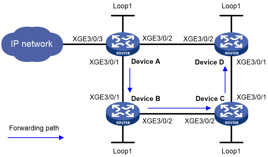
Table 2 Interface and IP address assignment
|
Device |
Interface |
IP address |
Device |
Interface |
IP address |
|
Device A |
Loop1 |
1::1/128 |
Device B |
Loop1 |
2::2/128 |
|
XGE3/0/1 |
1000::1/64 |
XGE3/0/1 |
1000::2/64 |
||
|
XGE3/0/2 |
4000::1/64 |
XGE3/0/2 |
2000::2/64 |
||
|
Device C |
Loop1 |
3::3/128 |
Device D |
Loop1 |
4::4/128 |
|
XGE3/0/1 |
3000::3/64 |
XGE3/0/1 |
3000::4/64 |
||
|
XGE3/0/2 |
2000::3/64 |
XGE3/0/2 |
4000::4/64 |
Prerequisites
1. Configure IPv6 addresses and prefix lengths for interfaces as shown in Table 2. (Details not shown.)
2. Configure an SRv6 TE policy:
¡ Configure Device A:
# Configure the SID list.
<DeviceA> system-view
[DeviceA] segment-routing ipv6
[DeviceA-segment-routing-ipv6] encapsulation source-address 1::1
[DeviceA-segment-routing-ipv6] locator a ipv6-prefix 5000:: 64 static 32 args 8
[DeviceA-segment-routing-ipv6-locator-a] opcode 1 end no-flavor
[DeviceA-segment-routing-ipv6-locator-a] quit
[DeviceA-segment-routing-ipv6] traffic-engineering
[DeviceA-srv6-te] srv6-policy locator a
[DeviceA-srv6-te] segment-list s1
[DeviceA-srv6-te-sl-s1] index 10 ipv6 6000::100
[DeviceA-srv6-te-sl-s1] index 20 ipv6 7000::100
[DeviceA-srv6-te-sl-s1] index 30 ipv6 8000::100
[DeviceA-srv6-te-sl-s1] quit
# Create an SRv6 TE policy and configure SRv6 TE policy attributes.
[DeviceA-srv6-te] policy p1
[DeviceA-srv6-te-policy-p1] binding-sid ipv6 5000::200
[DeviceA-srv6-te-policy-p1] color 10 end-point ipv6 4::4
[DeviceA-srv6-te-policy-p1] candidate-paths
[DeviceA-srv6-te-policy-p1-path] preference 10
[DeviceA-srv6-te-policy-p1-path-pref-10] explicit segment-list s1
[DeviceA-srv6-te-policy-p1-path-pref-10] quit
[DeviceA-srv6-te-policy-p1-path] quit
[DeviceA-srv6-te-policy-p1] quit
[DeviceA-srv6-te] quit
[DeviceA-segment-routing-ipv6] quit
# Configure IS-IS to achieve network layer communication and set the cost type as wide.
[DeviceA] isis 1
[DeviceA-isis-1] network-entity 00.0000.0000.0001.00
[DeviceA-isis-1] cost-style wide
[DeviceA-isis-1] address-family ipv6 unicast
[DeviceA-isis-1-ipv6] segment-routing ipv6 locator a
[DeviceA-isis-1-ipv6] quit
[DeviceA-isis-1] quit
[DeviceA] interface ten-gigabitethernet 3/0/1
[DeviceA-Ten-GigabitEthernet3/0/1] isis ipv6 enable 1
[DeviceA-Ten-GigabitEthernet3/0/1] quit
[DeviceA] interface ten-gigabitethernet 3/0/2
[DeviceA-Ten-GigabitEthernet3/0/2] isis ipv6 enable 1
[DeviceA-Ten-GigabitEthernet3/0/2] quit
[DeviceA] interface loopback 1
[DeviceA-LoopBack1] isis ipv6 enable 1
[DeviceA-LoopBack1] quit
¡ Configure Device B:
# Configure the SRv6 End.SID.
<DeviceB> system-view
[DeviceB] segment-routing ipv6
[DeviceB-segment-routing-ipv6] locator b ipv6-prefix 6000:: 64 static 32 args 8
[DeviceB-segment-routing-ipv6-locator-b] opcode 1 end no-flavor
[DeviceB-segment-routing-ipv6-locator-b] quit
[DeviceB-segment-routing-ipv6] quit
# Configure IS-IS to achieve network layer communication and set the cost type as wide.
[DeviceB] isis 1
[DeviceB-isis-1] network-entity 00.0000.0000.0002.00
[DeviceB-isis-1] cost-style wide
[DeviceB-isis-1] address-family ipv6 unicast
[DeviceB-isis-1-ipv6] segment-routing ipv6 locator b
[DeviceB-isis-1-ipv6] quit
[DeviceB-isis-1] quit
[DeviceB] interface ten-gigabitethernet 3/0/1
[DeviceB-Ten-GigabitEthernet3/0/1] isis ipv6 enable 1
[DeviceB-Ten-GigabitEthernet3/0/1] quit
[DeviceB] interface ten-gigabitethernet 3/0/2
[DeviceB-Ten-GigabitEthernet3/0/2] isis ipv6 enable 1
[DeviceB-Ten-GigabitEthernet3/0/2] quit
[DeviceB] interface loopback 1
[DeviceB-LoopBack1] isis ipv6 enable 1
[DeviceB-LoopBack1] quit
¡ Configure Device C:
# Configure the SRv6 End.SID.
<DeviceC> system-view
[DeviceC] segment-routing ipv6
[DeviceC-segment-routing-ipv6] locator c ipv6-prefix 7000:: 64 static 32 args 8
[DeviceC-segment-routing-ipv6-locator-c] opcode 1 end no-flavor
[DeviceC-segment-routing-ipv6-locator-c] quit
[DeviceC-segment-routing-ipv6] quit
# Configure IS-IS to achieve network layer communication and set the cost type as wide.
[DeviceC] isis 1
[DeviceC-isis-1] network-entity 00.0000.0000.0003.00
[DeviceC-isis-1] cost-style wide
[DeviceC-isis-1] address-family ipv6 unicast
[DeviceC-isis-1-ipv6] segment-routing ipv6 locator c
[DeviceC-isis-1-ipv6] quit
[DeviceC-isis-1] quit
[DeviceC] interface ten-gigabitethernet 3/0/1
[DeviceC-Ten-GigabitEthernet3/0/1] isis ipv6 enable 1
[DeviceC-Ten-GigabitEthernet3/0/1] quit
[DeviceC] interface ten-gigabitethernet 3/0/2
[DeviceC-Ten-GigabitEthernet3/0/2] isis ipv6 enable 1
[DeviceC-Ten-GigabitEthernet3/0/2] quit
[DeviceC] interface loopback 1
[DeviceC-LoopBack1] isis ipv6 enable 1
[DeviceC-LoopBack1] quit
¡ # Configure Device D:
# Configure the SRv6 End.SID.
<DeviceD> system-view
[DeviceD] segment-routing ipv6
[DeviceD-segment-routing-ipv6] locator d ipv6-prefix 8000:: 64 static 32 args 8
[DeviceD-segment-routing-ipv6-locator-d] opcode 1 end no-flavor
[DeviceD-segment-routing-ipv6-locator-d] quit
[DeviceD-segment-routing-ipv6] quit
# Configure IS-IS to achieve network layer communication and set the cost type as wide.
[DeviceD] isis 1
[DeviceD-isis-1] network-entity 00.0000.0000.0004.00
[DeviceD-isis-1] cost-style wide
[DeviceD-isis-1] address-family ipv6 unicast
[DeviceD-isis-1-ipv6] segment-routing ipv6 locator d
[DeviceD-isis-1-ipv6] quit
[DeviceD-isis-1] quit
[DeviceD] interface ten-gigabitethernet 3/0/1
[DeviceD-Ten-GigabitEthernet3/0/1] isis ipv6 enable 1
[DeviceD-Ten-GigabitEthernet3/0/1] quit
[DeviceD] interface ten-gigabitethernet 3/0/2
[DeviceD-Ten-GigabitEthernet3/0/2] isis ipv6 enable 1
[DeviceD-Ten-GigabitEthernet3/0/2] quit
[DeviceD] interface loopback 1
[DeviceD-LoopBack1] isis ipv6 enable 1
[DeviceD-LoopBack1] quit
Procedure
# Create a DetNet flow and configure the flow ID as 10, the destination IPv6 address as AD80::ABAA:0000:00C2:0002, and the IPv6 prefix length as 112.
[DeviceA] detnetip flow 10 destination-ipv6 AD80::ABAA:0000:00C2:0002 prefix 112
# Create a DetNet path with path ID 10 and enter its view.
[DeviceA] detnetip path 10
# Specify the path type as SRv6 for the DetNet path, and enter SRv6 DetNet path view.
[DeviceA-detnet-path10] type srv6
# Configure the Color value as 10 and the destination endpoint (Device D) IPv6 address as 4::4 for the SRv6 DetNet path.
[DeviceA-detnet-path10-srv6] policy color 10 end-point ipv6 4::4
[DeviceA-detnet-path10-srv6] quit
# Specify the source interface as Ten-GigabitEthernet3/0/3 for the DetNet path.
[DeviceA-detnet-path10] source interface ten-gigabitethernet 3/0/3
# Apply the DetNet path to DetNet flow 10.
[DeviceA-detnet-path10] apply flow 10
# Configure forwarding timeslots for nodes on the DetNet path: Specify queue 2 for the outgoing interface on the ingress edge node whose node index is 1, queue 5 for the outgoing interface on node 2, queue 8 for the outgoing interface on node 3, and queue 10 for the outgoing interface on node 4.+
[DeviceA-detnet-path10] timeslot hop 1 value 2
[DeviceA-detnet-path10] timeslot hop 2 value 5
[DeviceA-detnet-path10] timeslot hop 3 value 8
[DeviceA-detnet-path10] timeslot hop 4 value 10
[DeviceA-detnet-path10] quit
[DeviceA] quit
Verifying the configuration
<DeviceA> display detnetip path id 10
DetNet IP path information:
path id : 10
type : SRv6
source-interface : Ten-GigabitEthernet3/0/3
policy color : 10
end-point : 4::4
flow list : 10
timeslot : 2,5,8,10
