- Table of Contents
-
- 16-BRAS Services Configuration Guide
- 00-Preface
- 01-AAA configuration
- 02-ANCP configuration
- 03-PPP configuration
- 04-Value-added services configuration
- 05-DHCP configuration
- 06-DHCPv6 configuration
- 07-User profile configuration
- 08-Connection limit configuration
- 09-L2TP configuration
- 10-PPPoE configuration
- 11-IPoE configuration
- 12-802.1X configuration
- 13-UCM configuration
- Related Documents
-
| Title | Size | Download |
|---|---|---|
| 09-L2TP configuration | 682.39 KB |
Contents
L2TP tunnel establishment process
L2TP session establishment process
L2TP tunneling modes and L2TP user onboarding process
Restrictions and guidelines: L2TP configuration
Configuring basic L2TP capabilities
Configuring an LAC to initiate tunneling requests for a user
Configuring the source IP address of L2TP tunnel packets
Configuring each L2TP user to use an L2TP tunnel exclusively
Enabling transferring AVP data in hidden mode
Configuring AAA authentication on an LAC
Configuring an LAC to automatically establish an L2TP tunnel
Configuring the polling feature
Restoring the default settings for a virtual PPP interface
Configuring the time for which an LAC locks LNSs
Configuring an LNS to accept L2TP tunneling requests from an LAC
Configuring user authentication on an LNS
Configuring AAA authentication on an LNS
Setting the maximum number of ICRQ packets that the LNS can process per second
Setting the numbers of SCCRQ packets that the LNS can process per second
Enabling link compensation for an L2TP LNS
Configuring optional L2TP parameters
Configuring L2TP tunnel authentication
Setting the DSCP value of L2TP packets
Assigning a tunnel peer to a VPN
Setting the receiving window size for an L2TP tunnel
Setting the sending window size for an L2TP tunnel
Specifying an L2TP tunnel ID range
Configuring L2TP tunnel alarms
Setting the online L2TP session count alarm thresholds on the device
Enabling SNMP notifications for L2TP session addition failure
Display and maintenance commands for L2TP
Example: Configuring a client-initiated L2TP tunnel
Example: Configuring an LAC-auto-initiated L2TP tunnel
Example: Configuring L2TP tunneling switching
Configuring L2TP
About L2TP
The Layer 2 Tunneling Protocol (L2TP) is a Virtual Private Dialup Network (VPDN) tunneling protocol. L2TP sets up point-to-point tunnels across a public network (for example, the Internet) and transmits encapsulated PPP frames (L2TP packets) over the tunnels. With L2TP, remote users can access the private networks through L2TP tunnels after connecting to a public network by using PPP.
As a Layer 2 VPN technology, L2TP provides a secure, cost-effective solution for remote users to access private networks.
Typical L2TP networking
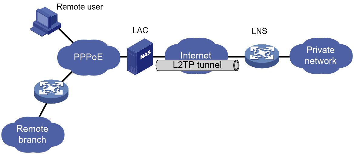
As shown in Figure 1, a typical L2TP network has the following components:
· Remote system—A remote system is usually a remote user's host or a remote branch's device that needs to access the private network.
· LAC—An L2TP access concentrator (LAC) is both PPP and L2TP capable. It is usually a network access server (NAS) located at a local ISP, which provides access services mainly for PPP users.
An LAC is an endpoint of an L2TP tunnel and lies between an LNS and a remote system. It encapsulates packets received from a remote system by using L2TP and then sends the encapsulated packets to the LNS. It decapsulates packets received from the LNS and then sends the decapsulated packets to the intended remote system.
· LNS—An L2TP network server (LNS) is both PPP and L2TP capable. It is usually an edge device on an enterprise network.
An LNS is the other endpoint of an L2TP tunnel. It is the logical termination point of a PPP session tunneled by the LAC. L2TP extends the termination point of a PPP session from a NAS to an LNS by establishing a tunnel.
L2TP message packets
L2TP message types and encapsulation structures
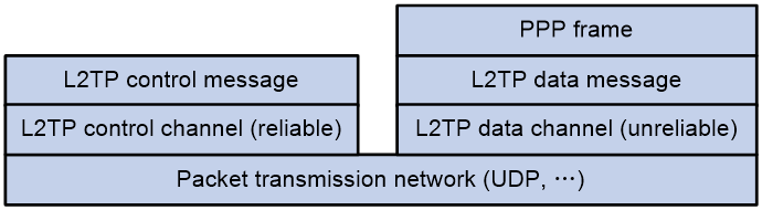
As shown in Figure 2, the L2TP protocol defines two types of messages: L2TP control messages and L2TP data messages.
· Control message—Used to establish, maintain, and tear down L2TP tunnels and sessions. Control messages are transmitted over a reliable control channel, which supports flow control and congestion control.
· Data messages—Used to encapsulate PPP frames. Data messages are transmitted over an unreliable data channel and are not retransmitted when packet loss occurs. Data messages can use sequence numbers to reorder packets that are disordered during transport.
Figure 2 L2TP protocol structure diagram
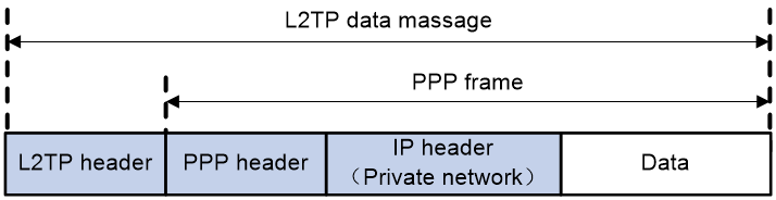
As shown in Figure 3, L2TP control messages and L2TP data messages are both encapsulated in UDP packets.
Figure 3 L2TP message encapsulation structure diagram
![]()
The L2TP data message format is as shown in Table 1.
Table 1 L2TP data message format
L2TP packet header
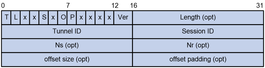
The control messages and data messages of L2TP use the same L2TP packet header format as shown in Figure 4. For the meaning of each field in the L2TP packet header, see Table 2.
Figure 4 L2TP packet header format
|
|
NOTE: · A field with the opt tag in the L2TP packet header means the field is optional in data messages and required in control messages. · The L2TP packet header contains the tunnel ID and session ID, which are allocated by the peer to identify different tunnels and sessions. Packets with the same tunnel ID but different session IDs will be multiplexed on the same tunnel. |
Table 2 Fields in the L2TP packet header
|
Field |
Description |
Value requirement |
|
T |
Type. The value of 0 indicates data message, and the value of 1 indicates control message. |
The value must be 1 in a control message. |
|
L |
Indicates whether the length field is present. The value of 1 indicates the presence of the length field in the packet header. |
The value must be 1 in a control message. |
|
x |
Reserved bits. |
N/A |
|
S |
Indicates whether the sequence fields are present. The value of 1 indicates the presence of the Ns and Nr fields in the packet header. |
The value must be 1 in a control message. |
|
O |
The value of 1 indicates that the offset size field exists in the packet header. |
The value must be 0 in a control message. |
|
P |
Priority, used only for data messages. |
The value must be 0 in a control message. |
|
Ver |
Version number. |
The value for the L2TPv2 protocol is 2. |
|
Length |
Total length of the message, measured in bytes. |
N/A |
|
Tunnel ID |
Tunnel ID, which has local significance only. |
Hello control messages have global significance, and their tunnel ID must be 0. |
|
Session ID |
Session ID, which has local significance only. |
N/A |
|
Ns |
Sequence number of the current message. |
N/A |
|
Nr |
Sequence number expected in the next control message to be received. |
In data messages, this field is reserved. |
|
offset size |
Offset value, indicating the start position of the payload data. |
N/A |
|
offset padding |
Padding bits. |
N/A |
L2TP data packet structure
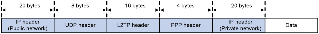
As shown in Figure 5, the user PPP packet (with the source IP packet header and PPP packet header) carries the following protocol headers when transmitted in the public network as an IP packet:
· One L2TP packet header (16 bytes)
· One UDP packet header (8 bytes)
· One new IP packet header (20 bytes), which indicates the source address and destination address of the L2TP tunnel.
Figure 5 L2TP data packet format
An LAC encapsulates a received PPP packet as follows:
1. First, encapsulates it with the L2TP packet header.
2. Then, encapsulates the UDP packet header.
3. Then, encapsulates the new IP header and sends the packet out the interface connected to the public network. The new IP header's address is the IP address of the tunnel destination.
An LNS processes the packet as follows after receiving the packet from the interface connected to the public network:
1. Removes the IP header and UDP header, and sends the packet to the L2TP protocol module.
2. The L2TP protocol removes the L2TP protocol header and PPP header, restores the packet to the user IP packet, and sends the packet to the internal server in the private network.
|
|
NOTE: · L2TP does not support data fragmentation. After an L2TP packet is encapsulated with an IP header, the IP packet can be fragmented as required. When multiple paths exist between an LAC and LNS, a fragmented packet might fail to be reassembled on the LAC. To ensure that no packet is fragmented, make sure the size of the encapsulated IP packet is not greater than the MTU of the actual physical interface. · As a best practice to avoid fragmentation of encapsulated packets when L2TP carries only TCP services, preferentially use the tcp modify-mss command in system view to configure a small TCP MSS. · When L2TP carries multiple services such as TCP and UDP, make sure the MTU configured for the VT interface on the LNS is equal to or less than the MTU of the actual interface connecting the LNS to the LAC minus 48 as a best practice. If mandatory LCP renegotiation is not configured on the LNS, the MTU configuration for a VT interface does not take effect. To configure the MTU for a VT interface, you must also configure mandatory LCP renegotiation on the LNS. |
L2TP tunnel and session
An L2TP tunnel is a virtual point-to-point connection between an LAC and an LNS. Multiple L2TP tunnels can be established between an LNS and an LAC. An L2TP tunnel can carry one or more L2TP sessions. Each L2TP session corresponds to a PPP session and is multiplexed on an L2TP tunnel. An L2TP session is established between the LAC and LNS when an end-to-end PPP session is established between a remote system and the LNS. Data frames for the PPP session are transmitted over the tunnel between the LAC and LNS.
L2TP tunnel establishment process
L2TP tunnel messages
Messages involved in L2TP tunnel establishment include:
· SCCRQ— Start-Control-Connection-Request, used to request the establishment of an L2TP tunnel to the peer.
· SCCRP—Start-Control-Connection-Reply, used to inform the peer that this end has received the peer's SCCRQ message and allows the establishment of the L2TP tunnel.
· SCCCN—Start-Control-Connection-Connected, used to inform the peer that this end has received the SCCRP messages from the peer and has completed the establishment of the tunnel.
· StopCCN—Stop-Control-Connection-Notification, used to notify the peer to tear down the L2TP tunnel.
· Hello—Used to detect the connectivity of the tunnel.
· ZLB—Zero-Length Body. If the local queue has no messages to send, the local end sends a ZLB message to the peer. During the L2TP tunnel teardown process, the sender must send a StopCCN message, and the receiver sends a ZLB message. A ZLB message only has an L2TP header and has no payload part.
L2TP tunnel establishment
The establishment of an L2TP tunnel precedes that of an L2TP session. An L2TP session can be established only when an L2TP tunnel has been successfully established. The L2TP tunnel establishment process is as shown in Figure 6.
Figure 6 Three-way handshake for L2TP tunnel establishment

The basic process of L2TP tunnel establishment is as follows:
1. Once the LAC and LNS can reach each other at Layer 3, the LAC sets the corresponding AVPs and sends an SCCRQ packet to the LNS to request the establishment of an L2TP tunnel.
2. Upon receiving the SCCRQ packet from the LAC, the LNS sends an SCCRP packet to the LAC if the LNS agrees to establish the tunnel based on the AVPs included in the SCCRQ packet.
3. After receiving the SCCRP packet from the LNS, the LAC extracts tunnel information from the SCCRP packet and sends an SCCCN packet to the LNS, indicating successful L2TP tunnel establishment.
L2TP tunnel authentication process
Tunnel authentication and tunnel establishment are performed simultaneously rather than separately.
The tunnel authentication process is as follows:
1. First, when an LAC sends an SCCRQ packet to an LNS, the LAC generates a random string as its own CHAP Challenge (the field carried by SCCRQ) and sends the string to the LNS.
2. After receiving the SCCRQ packet, the LNS generates a 16-byte Response by using the CHAP Challenge sent by the LAC side and the password configured on the LNS. The LNS also generates a random string (LNS CHAP Challenge) and sends this random string and Response together in the SCCRQ packet to the LAC.
3. The LAC authenticates the LNS after receiving the SCCRQ packet.
¡ The LAC uses its CHAP Challenge and the password configured on the LAC to generate a new 16-byte string.
¡ The LAC compares the newly generated string with the LNS CHAP Response carried in the SCCRQ packet received from the LNS. If they match, the tunnel will pass authentication. If they do not match, the tunnel will be torn down.
4. If authentication succeeds, the LAC sends its CHAP Response in the SCCCN packet to the LNS.
5. After receiving the SCCCN packet, the LNS also performs authentication as follows:
¡ The LNS uses its CHAP Challenge and the locally configured password to generate a 16-byte string.
¡ The LNS compares the string with the LAC CHAP Response in the received SCCCN packet. If they match, authentication will succeed. If they do not match, the tunnel will be torn down.
Maintenance of an L2TP tunnel
As shown in Figure 7, L2TP uses Hello packets to detect the connectivity of a tunnel. The LAC and LNS periodically send Hello packets to each other, and the receiver responds upon receiving the Hello packets. When the LAC or LNS does not receive a Hello response from the peer within the specified interval, it resends the Hello packet. If no response is received after five attempts, the L2TP tunnel is considered disconnected.
Figure 7 Maintenance of an L2TP tunnel

|
|
NOTE: · By default, the Hello packets are sent every 60 seconds. The Hello interval can be manually configured by using the tunnel timer hello command. · The LAC and LNS can set different Hello intervals. |
Teardown of an L2TP tunnel
As shown in Figure 8, either the LAC or LNS can initiate the teardown of an L2TP tunnel. The initiator notifies the peer to tear down the L2TP tunnel by sending a StopCCN message to the peer. Upon receiving the StopCCN message, the peer responds with a ZLB ACK message and maintains the L2TP tunnel for a certain period of time to prevent the loss of the ZLB ACK message.
Figure 8 Teardown of an L2TP tunnel

L2TP session establishment process
L2TP session messages
During the L2TP session establishment process, the messages involved include:
· ICRQ—Incoming Call Request. Only the LAC will send this message. Whenever a user's call request is detected, the LAC sends an ICRQ message to the LNS to request establishing an L2TP session. The ICRQ message carries session parameters.
· ICRP—Incoming-Call-Reply. Only the LNS will send this message. When the LNS receives an ICRQ message from an LAC, the LNS replies with an ICRP message to allow establishing the L2TP session.
· ICCN—Incoming-Call-Connected. Only the LAC will send this message. After receiving an ICRP message from an LNS, an LAC replies with an ICCN message to notify the LNS to establish an L2TP session.
· CDN—Call-Disconnect-Notify. This message is used to notify the peer to tear down the L2TP session and inform the peer end of the teardown reason.
· ZLB—Zero-Length Body. If the local queue has no messages to send, the local end sends a ZLB message to the peer. During the teardown process of the L2TP session, sending a ZLB messages also indicates receiving a CDN message. A ZLB message only has an L2TP header and has no payload part.
L2TP session establishment
After the L2TP tunnel is successfully established, the LAC sends an L2TP session establishment request to the LNS once it detects a user call. The L2TP session establishment process is as shown in Figure 9.
Figure 9 L2TP session establishment process
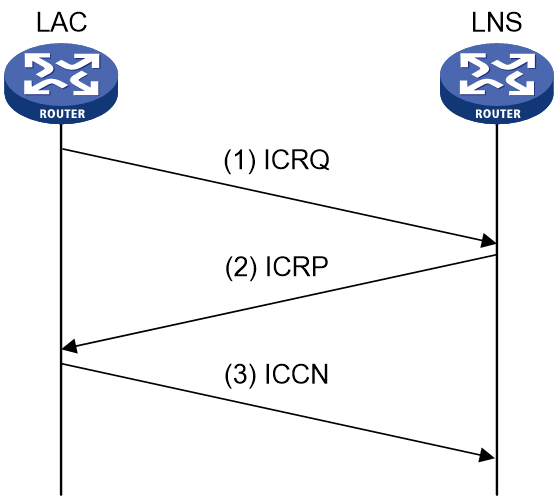
The basic process of establishing an L2TP session is as follows:
1. After the L2TP tunnel is successfully established, the LAC sends an ICRQ message to the LNS to request establishing an L2TP session upon detecting a user call.
2. After receiving the ICRQ from the LAC, the LNS sends an ICRP to the LAC to allow L2TP session establishment.
3. After receiving the ICRP message from the LNS, the LAC replies to the LNS with an ICCN message, indicating that the LAC has responded to the user call and notifying the LNS to establish the L2TP session.
L2TP session teardown
As shown in Figure 10, either the LAC or the LNS can initiate teardown of the L2TP session. The initiator notifies the peer to tear down the L2TP session by sending a CDN message to the peer. The peer responds with a ZLB ACK message upon receiving the CDN message.
Figure 10 L2TP session teardown

L2TP tunneling modes and L2TP user onboarding process
L2TP tunneling modes include NAS-initiated, client-initiated, and LAC-auto-initiated.
NAS-initiated tunneling mode
As shown in Figure 11, a remote system dials in to the LAC through a PPPoE network. The LAC initiates a tunneling request to the LNS over the Internet.
Figure 11 NAS-initiated tunneling mode
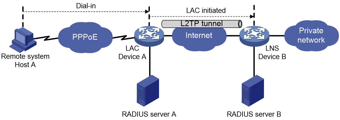
A NAS-initiated tunnel has the following characteristics:
· The remote system only needs to support PPP, and it does not need to support L2TP.
· Authentication and accounting of the remote system can be implemented on the LAC or LNS.
Figure 12 NAS-initiated tunnel establishment process
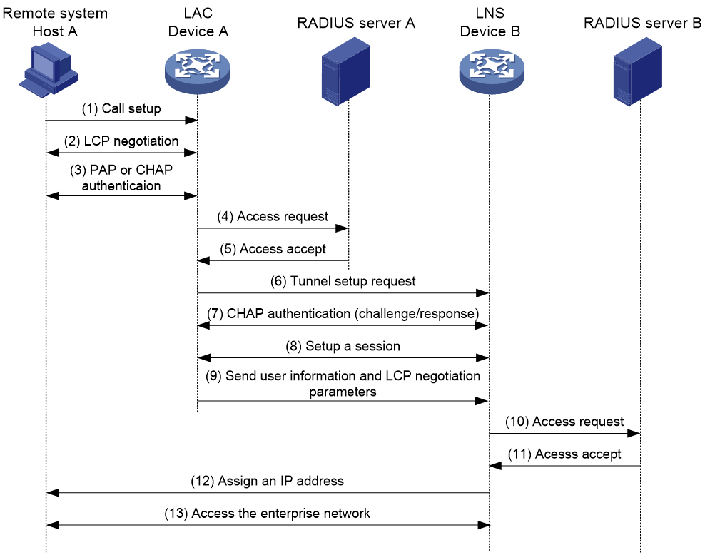
As shown in Figure 12, the following workflow is used to establish a NAS-initiated tunnel:
1. A remote system (Host A) initiates a PPP connection to the LAC (Device A).
2. The remote system and LAC perform PPP LCP negotiation.
3. The LAC authenticates PPP user information of Host A by using PAP or CHAP.
4. The LAC sends the authentication information (username and password) to its RADIUS server (RADIUS server A) for authentication.
5. RADIUS server A authenticates the user and returns the result.
6. The LAC initiates an L2TP tunneling request to the LNS (Device B) when the following conditions exist:
¡ The user passes the authentication.
¡ The user is determined to be an L2TP user according to the username or the ISP domain to which the user belongs.
7. If tunnel authentication is needed, the LAC and LNS send CHAP challenge messages to authenticate each other before successfully establishing an L2TP tunnel.
8. The LAC and LNS negotiate to establish L2TP sessions.
9. The LAC sends PPP user information and PPP negotiation parameters to the LNS.
10. The LNS sends the authentication information to its RADIUS server (RADIUS server B) for authentication.
11. RADIUS server B authenticates the user and returns the result.
12. If the user passes the authentication, the LNS assigns a private IP address to the remote system (Host A).
13. The PPP user can access internal resources of the enterprise.
In steps 12 and 13, the LAC forwards packets for the remote system and LNS. Host A and LAC exchange PPP frames, and the LAC and LNS exchange L2TP packets.
Client-initiated tunneling mode
As shown in Figure 13, a remote system running L2TP (LAC client) has a public IP address to communicate with the LNS through the Internet. The LAC client can directly initiate a tunneling request to the LNS without any dedicated LAC devices.
Figure 13 Client-initiated tunneling mode
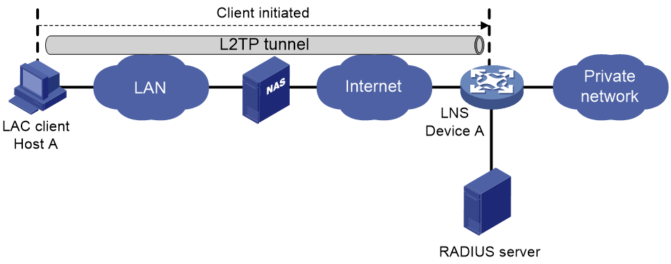
A client-initiated tunnel has the following characteristics:
· A client-initiated tunnel has higher security because it is established between a remote system and the LNS.
· The remote system must support L2TP and be able to communicate with the LNS. This causes poor expandability.
As shown in Figure 14, the workflow for establishing a client-initiated tunnel is similar to that for establishing a NAS-initiated tunnel. (Details not shown.)
Figure 14 Client-initiated tunnel establishment process

LAC-auto-initiated tunneling mode
In NAS-initiated mode, a remote system must successfully dial in to the LAC through PPPoE.
In LAC-auto-initiated mode, you can use the l2tp-auto-client command on the LAC to trigger the LAC to initiate a tunneling request to the LNS. When a remote system accesses the private network, the LAC forwards data through the L2TP tunnel.
Figure 15 LAC-auto-initiated tunneling mode

An LAC-auto-initiated tunnel has the following characteristics:
· The connection between a remote system and the LAC is not confined to a dialup connection and can be any IP-based connection.
· An L2TP session is established immediately after an L2TP tunnel is established. Then, the LAC and LNS, acting as the PPPoE client and PPPoE server, respectively, perform PPP negotiation.
· The LNS assigns a private IP address to the LAC instead of to the remote system.
As shown in Figure 16, the workflow for establishing an LAC-auto-initiated tunnel is similar to that for establishing a NAS-initiated tunnel. (Details not shown.)
Figure 16 Establishment process for LAC-auto-initiated tunnels

L2TP features
· Flexible identity authentication mechanism and high security—L2TP by itself does not provide security for connections. However, it has all the security features of PPP and allows for PPP authentication (CHAP or PAP).
L2TP can also cooperate with IPsec to improve security for tunneled data.
· Multiprotocol transmission—L2TP tunnels PPP frames, which can be used to encapsulate packets of multiple network layer protocols.
· RADIUS authentication—An LAC or LNS can send the username and password of a remote user to a RADIUS server for authentication.
· Private address allocation—An LNS can dynamically allocate private addresses to remote users. This facilitates address allocation for private internets (RFC 1918) and improves security.
· Flexible accounting—Accounting can be simultaneously performed on the LAC and LNS. This allows bills to be generated on the ISP side and charging and auditing to be processed on the enterprise gateway. L2TP can provide accounting data, including inbound and outbound traffic statistics (in packets and bytes) and the connection's start time and end time. The AAA server uses these data for flexible accounting.
· Reliability—L2TP supports LNS backup. When the connection to the primary LNS is torn down, an LAC can establish a new connection to a secondary LNS. This redundancy enhances the reliability of L2TP services.
· Issuing tunnel attributes by RADIUS server to LAC—In NAS-initiated mode, the tunnel attributes can be issued by the RADIUS server to the LAC. For the LAC to receive these attributes, enable L2TP and configure remote AAA authentication for PPP users on the LAC.
When an L2TP user dials in to the LAC, the LAC as the RADIUS client sends the user information to the RADIUS server. The RADIUS server authenticates the PPP user, returns the result to the LAC, and issues L2TP tunnel attributes for the PPP user to the LAC. The LAC then sets up an L2TP tunnel and sessions based on the issued L2TP tunnel attributes.
Table 3 Major tunnel attributes that can be issued by the RADIUS server
|
Attribute number |
Attribute name |
Description |
|
64 |
Tunnel-Type |
Tunnel type, which can only be L2TP. |
|
65 |
Tunnel-Medium-Type |
Transmission medium type for the tunnel, which can only be IPv4. |
|
66 |
Tunnel-Client-Endpoint |
Tunnel source IP address. |
|
67 |
Tunnel-Server-Endpoint |
IP address of the LNS. |
|
69 |
Tunnel-Password |
Key used to authenticate a peer of the tunnel. |
|
81 |
Tunnel-Private-Group-Id |
Group ID for the tunnel. The LAC sends this value to the LNS for the LNS to perform an operation accordingly. |
|
82 |
Tunnel-Assignment-Id |
Assignment ID for the tunnel. It is used to indicate the tunnel to which a session is assigned. L2TP users with the same Tunnel-Assignment-Id, Tunnel-Server-Endpoint, and Tunnel-Password attributes share an L2TP tunnel. |
|
83 |
Tunnel-Preference |
Tunnel preference. It is used to indicate the preference of a tunnel. A smaller value means a higher preference. |
|
90 |
Tunnel-Client-Auth-Id |
Tunnel name on the LAC. It is used to indicate the local tunnel. |
A RADIUS server-issued tunnel can be set up only when the RADIUS server issues attribute 64 (Tunnel-Type) with the tunnel type as L2TP.
When RADIUS is used to authorize tunnel attributes and set up tunnels, the following rules apply:
¡ If the RADIUS-issued tunnel attributes are the same as the tunnel attributes manually configured on the LAC, the RADIUS-issued attributes apply.
¡ If the RADIUS server has not issued some tunnel attributes, the manually configured tunnel attributes apply.
¡ If the RADIUS server has issued attributes 83 (Tunnel-Preference) to LNS IPs, the LAC tries to establish connections to LNSs in descending order of preference until a connection is successfully established. If multiple LNSs have the same preference, the LAC establishes tunnels to these LNSs in load sharing mode.
¡ The RADIUS server supports issuing multiple groups of different attributes to a LAC. For example, the RADIUS server can issue different tunnel passwords to different LNS IPs for tunnel establishment.
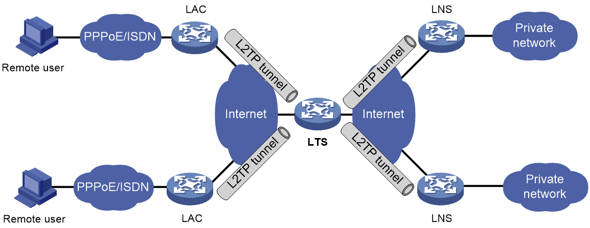
· L2TP tunnel switching—Also called multihop L2TP tunneling. As shown in Figure 17, the Layer 2 tunnel switch (LTS) terminates L2TP packets from each LAC as an LNS. It then sends these packets to a destination LNS as an LAC.
L2TP tunnel switching has the following features:
¡ Simplified configuration and deployment—When LACs and LNSs are in different management domains:
- All LACs consider the LTS as an LNS and do not need to differentiate LNSs on the network.
- All LNSs consider the LTS as an LAC and are not affected by the addition or deletion of LACs.
¡ L2TP tunnel sharing—Different users can share the same L2TP tunnel between the LAC and the LTS. The LTS distributes data of different users to different LNSs.
Figure 17 L2TP tunnel switching network diagram
Protocols and standards
· RFC 1661, The Point-to-Point Protocol (PPP)
· RFC 1918, Address Allocation for Private Internets
· RFC 2661, Layer Two Tunneling Protocol "L2TP"
· RFC 2868, RADIUS Attributes for Tunnel Protocol Support
Restrictions and guidelines: L2TP configuration
In standard system operating mode, this feature is available only for the following cards:
Table 4 Card information
|
Card category |
Cards |
|
CSPEX |
CSPEX-1304S, CSPEX-1404S, CSPEX-1504S |
In SDN-WAN system operating mode, this feature is not supported.
Suppose an LAC is configured with both the NAS-initiated and LAC-auto-initiated tunneling modes. If the ppp authentication-mode command is executed on a virtual PPP interface on the LAC to authenticate the LNS, make sure usernames configured by using the following methods are different:
· Username configured by using the user fullusername command in L2TP group view on the LAC. (NAS-initiated mode.)
· Username configured by using the ppp pap local-user or ppp chap user command on a VT interface on the LNS (username that the LNS as the suppliant sends to the LAC as the authenticator).
Otherwise, L2TP cannot operate properly.
L2TP tasks at a glance
LAC tasks at a glance
To configure an LAC, complete the following tasks:
1. Configuring basic L2TP capabilities
¡ Configuring an LAC to initiate tunneling requests for a user
This task is required for NAS-initiated mode and unnecessary for LAC-auto-initiated mode.
¡ Configuring the source IP address of L2TP tunnel packets
¡ (Optional.) Configuring each L2TP user to use an L2TP tunnel exclusively
¡ (Optional.) Enabling transferring AVP data in hidden mode
¡ Configuring AAA authentication on an LAC
This task is required for NAS-initiated mode and unnecessary for LAC-auto-initiated mode.
¡ Configuring an LAC to automatically establish an L2TP tunnel
This task is required for NAS-initiated mode and unnecessary for LAC-auto-initiated mode.
¡ (Optional.) Configuring the polling feature
¡ (Optional.) Restoring the default settings for a virtual PPP interface
¡ (Optional.) Configuring the time for which an LAC locks LNSs
¡ (Optional.) Configuring the maximum value supported by the Connect Speed field in the ICCN messages sent by the LAC
3. (Optional.) Configuring optional L2TP parameters
¡ Configuring L2TP tunnel authentication
¡ Setting the DSCP value of L2TP packets
¡ Setting the TSA ID of the LTS
¡ Setting the receiving window size for an L2TP tunnel
¡ Setting the sending window size for an L2TP tunnel
¡ Specifying an L2TP tunnel ID range
¡ Configuring L2TP tunnel alarms
4. (Optional.) Setting the online L2TP session count alarm thresholds on the device
5. (Optional.) Enabling SNMP notifications for L2TP session addition failure
LNS tasks at a glance
1. Configuring basic L2TP capabilities
¡ Configuring an LNS to accept L2TP tunneling requests from an LAC
¡ (Optional.) Configuring user authentication on an LNS
¡ (Optional.) Configuring AAA authentication on an LNS
¡ (Optional.) Setting the maximum number of ICRQ packets that the LNS can process per second
¡ (Optional.) Setting the numbers of SCCRQ packets that the LNS can process per second
¡ (Optional.) Enabling link compensation for an L2TP LNS
3. (Optional.) Configuring optional L2TP parameters
¡ Configuring L2TP tunnel authentication
¡ Setting the DSCP value of L2TP packets
¡ Setting the TSA ID of the LTS
¡ Setting the receiving window size for an L2TP tunnel
¡ Setting the sending window size for an L2TP tunnel
¡ Specifying an L2TP tunnel ID range
¡ Configuring L2TP tunnel alarms
4. (Optional.) Setting the online L2TP session count alarm thresholds on the device
5. (Optional.) Enabling SNMP notifications for L2TP session addition failure
Prerequisites for L2TP
When you configure L2TP, perform the following tasks:
1. Determine the network devices needed according to the networking environment.
¡ For NAS-initiated mode and LAC-auto-initiated mode, configure both the LAC and the LNS.
¡ For client-initiated mode, you only need to configure the LNS.
2. Configure the devices based on the intended role (LAC or LNS) on the network.
Configuring basic L2TP capabilities
About this task
Basic L2TP capability configuration includes the following tasks:
· Enabling L2TP—L2TP must be enabled for L2TP configurations to take effect.
· Creating an L2TP group—An L2TP group is intended to represent a group of parameters. This enables not only flexible L2TP configuration on devices, but also one-to-one and one-to-many networking applications for LACs and LNSs. An L2TP group has local significance only. However, the relevant settings of the L2TP groups on the LAC and LNS must match. For example, the local tunnel name configured on the LAC must match the tunnel peer name configured on the LNS.
· Configuring the local tunnel name—The local tunnel name identifies the tunnel at the local end during tunnel negotiation between an LAC and an LNS.
Restrictions and guidelines
A tunnel to an LNS from an LAC is established by using one of the following methods:
· Method 1: Execute the l2tp-group group-number mode lac command to create an L2TP group. This method is supported by the NAS-Initiated and LAC-Auto-Initiated modes.
· Method 2: The RADIUS server issues tunnel attributes to the LAC directly. This method is supported only by the NAS-Initiated mode.
In NAS-Initiated mode, if both methods are used, method 2 takes priority.
· If the RADIUS server issues attribute 64 (tunnel-type) to the LAC and the tunnel type is L2TP, the following rules apply when the L2TP tunnel is established:
¡ If a tunnel attribute issued by the RADIUS server is also configured at the CLI, the tunnel attribute issued by the RADIUS server applies.
¡ If a tunnel attribute is not issued by the RADIUS server, the tunnel attribute configured at the CLI on the LAC applies.
· If the RADIUS server does not issue attribute 64 (tunnel-type) to the LAC, the settings manually configured at the CLI on the LAC apply.
· If the RADIUS server issues attribute 64 (tunnel-type) to the LAC but the tunnel type is not L2TP, the L2TP tunnel cannot be established.
Procedure
1. Enter system view.
system-view
2. Enable L2TP.
l2tp enable
By default, L2TP is disabled.
3. Create an L2TP group, specify its mode, and enter its view.
l2tp-group group-number [ group-name group-name ] mode { lac | lns }
Specify the mode as lac on the LAC side and as lns on the LNS side.
4. Specify the local tunnel name.
tunnel name name
By default, the device name is used.
The local tunnel name configured on the LAC must match the tunnel peer name configured on the LNS.
Configuring an LAC
Configuring an LAC to initiate tunneling requests for a user
About this task
This task configures an LAC to initiate tunneling requests to an LNS for a user. When the PPP user information matches the specified user, the LAC determines that the PPP user is an L2TP user and initiates tunneling requests to the LNS.
You can specify a user by configuring one of the following items:
· L2TP group specified for the domain—If an L2TP group is specified by using the l2tp-group command in the ISP domain of PPP users, users in the ISP domain are all considered as L2TP users. After a user passes authentication, the user can initiate tunneling requests to the LNS.
· Fully qualified name—The LAC initiates tunneling requests to the LNS only if the username of a PPP user matches the configured fully qualified name.
· Domain name—The LAC initiates tunneling requests to the LNS only if the ISP domain name of a PPP user matches the configured domain name.
Restrictions and guidelines
When a user dials to a LAC and passes authentication, the LAC processes the user as follows:
· If the ISP domain of the dialup user has been configured with an L2TP group by using the l2tp-group command, all users in the ISP domain are considered as L2TP users. After a user passes authentication, the user initiates tunneling requests to the LNS.
· If the ISP domain of the dialup user is not configured with an L2TP group by using the l2tp-group command, the following rules apply:
¡ The LAC compares the username of the dialup user with the full usernames configured by using the fullusername user-name command for all L2TP groups on the LAC. If the username matches the full username of an L2TP group, the user uses the L2TP group to initiate tunneling requests.
¡ If the username does not match the full username of any L2TP group, the LAC compares the ISP domain name of the dialup user with the domain names configured by using the domain domain-name command for all L2TP groups on the LAC. If the ISP domain name matches the domain name of an L2TP group, the user uses the L2TP group to initiate tunneling requests. If no matching domain name is found, the user cannot initiate tunneling requests.
The ISP domain name is selected in the following order for a dialup user:
1. AAA-authorized ISP domain name. If the AAA-authorized ISP domain name does not match the domain name of any L2TP group on the LAC, proceed with the following steps.
2. ISP domain name used in PPP authentication. For how an ISP domain is selected in PPP authentication, see “Configuring PPP.”
¡ If the domain name used in PPP authentication is a forced PPP authentication domain name but the domain name does not match the domain name of any L2TP group on the LAC, the following rules apply:
- If the username carries a domain name, the LAC compares the domain name in the username with the domain names of all L2TP groups on the LAC. If the domain name of an L2TP group is matched, the user uses the L2TP group to initiate tunneling requests.
- If no match is found, the user cannot initiate tunneling requests.
- If the username does not carry a domain name, the user cannot initiate tunneling requests.
¡ If the domain name used in PPP authentication is the domain name carried in the username, non-forced PPP authentication domain name, or AAA-authorized domain name, the LAC compares the used domain name with the domain names of all L2TP groups on the LAC.
- If the used domain name matches the domain name of an L2TP group, the user users the L2TP group to initiate tunneling requests.
- If the used domain does not match the domain name of any L2TP group, the user cannot initiate tunneling requests.
The domain name and full username of an L2TP group must be unique among all L2TP groups.
If the l2tp-user radius-force command has not been executed in the ISP domain of users, the following rules apply:
· If the RADIUS server has issued attribute 64 (tunnel-type) to a user and the tunnel type is L2TP, the following rules apply when an L2TP tunnel is established:
¡ The tunnel attribute issued by the RADIUS server is preferentially used.
¡ If a tunnel attribute is not issued by the RADIUS server, an L2TP group is selected in the following order to use its attributes:
- L2TP group (attribute 183, H3C-Tunnel-Group-Name) authorized by RADIUS.
- L2TP group specified in an ISP domain by using the l2tp-group command in ISP domain view.
- L2TP group configured by using the l2tp-group command in system view matched by username or domain name.
- Default L2TP group configured by using the default-lac-group enable command in L2TP group view.
· If the RADIUS server does not issue attribute 64 to the user, the device uses settings in a selected L2TP group for establishing a tunnel. An L2TP group is selected in the following order:
a. L2TP group (attribute 183, H3C-Tunnel-Group-Name) authorized by RADIUS.
b. L2TP group specified in an ISP domain by using the l2tp-group command.
c. L2TP group configured in system view by using the l2tp-group command matched by username or domain name.
If the l2tp-user radius-force command has been executed in the ISP domain of users, a PPP user is considered an L2TP user and processed only when the RADIUS server issues attribute 64 (tunnel-type) to the user and the tunnel type is L2TP. In this case, L2TP tunnel attributes are selected in the following order:
· The tunnel attribute issued by the RADIUS server is preferentially used.
· If a tunnel attribute is not issued by the RADIUS server, an L2TP group is selected in the following order to use its attributes:
¡ L2TP group (attribute 183, H3C-Tunnel-Group-Name) issued by RADIUS.
¡ L2TP group specified in an ISP domain by using the l2tp-group command in ISP domain view.
¡ L2TP group configured in system view by using the l2tp-group command in system view matched by username or domain name.
¡ Default L2TP group configured by using the default-lac-group enable command in L2TP group view.
For more information about the l2tp-user radius-force command and the l2tp-group command in ISP domain view, see AAA in BRAS Services Command Reference.
Procedure
1. Enter system view.
system-view
2. Initiate tunneling requests to the LNS. Choose at least one of the following tasks:
¡ Configure the LAC to initiate tunneling requests for a user.
Enter the view of an L2TP group in LAC mode.
l2tp-group group-number [ group-name group-name ] [ mode lac ]
Configure the LAC to initiate tunneling requests for a user.
user { domain domain-name | fullusername user-name }
By default, an LAC does not initiate tunneling requests for any users.
¡ Specify the L2TP group used by L2TP users in an ISP domain.
Enter ISP domain view.
domain name isp-name
Specify the L2TP group used by L2TP users in the ISP domain.
l2tp-group { group-name group-name | group-number group-number }
By default, no L2TP group is specified for L2TP users in an ISP domain.
With this command executed in an ISP domain, all users in the ISP domain are considered as L2TP users. After a user passes authentication, the user initiates tunneling requests to the LNS.
¡ Configure an L2TP group as the default L2TP group:
- Enter L2TP group (LAC mode) view.
l2tp-group group-number [ group-name group-name ] [ mode lac ]
- Configure the L2TP group as the default L2TP group.
default-lac-group enable
By default, an L2TP group is not the default L2TP group.
If the RADIUS server issues tunnel attributes to the LAC directly to create a tunnel, the default L2TP group role takes effect. If L2TP tunnels are established in any other method, the default L2TP group role does not take effect.
If the RADIUS server issues tunnel attributes to the LAC directly to create a tunnel, use the default L2TP group for the following purposes:
- Supplement tunnel attributes for the users that do not match any other L2TP groups if the RADIUS server does not issue all required tunnel attributes.
- Supplement tunnel attributes for users in different authentication domains or authorization domains to simplify configuration.
Specifying LNS IP addresses
About this task
You can specify up to five LNS IP addresses for an LAC. An LAC can operate in master/backup mode or load sharing mode.
· Master/backup mode—When the lns-ip command is executed to configure multiple LNS addresses, the LAC tries to establish a connection to an LNS in the LNS address configuration order until a connection to an LNS is successfully established. The LNS that successfully establishes a connection is called the master LNS, and the other LNSs are backup LNSs. An LAC tries to establish a connection to a backup LNS until the master LNS fails.
· Load sharing mode—When the lns-ip command is executed to configure multiple LNS addresses, the LAC distributes the L2TP services among the specified LNSs according to their weights.
Procedure
1. Enter system view.
system-view
2. Enter the view of an L2TP group in LAC mode.
l2tp-group group-number [ group-name group-name ] [ mode lac ]
3. (Optional.) Configure the LAC to operate in load sharing mode.
tunnel load-sharing
By default, an LAC operates in master/backup mode.
When a single LNS cannot meet large L2TP service requirements, you can configure the LAC to operate in load sharing mode for performance and reliability.
4. Specify LNS IP addresses.
lns-ip { ip-address [ weight lns-weight ] }&<1-5>
By default, no LNS IP addresses are specified.
The weight parameter configuration takes effect only when the LAC operates in load sharing mode.
Configuring the source IP address of L2TP tunnel packets
About this task
The L2TP tunnel source IP address configured on an LAC is used as the source IP address of L2TP tunnel packets.
Restrictions and guidelines
For high availability, as a best practice, use the IP address of a loopback interface as the source IP address of L2TP tunnel packets on the LAC. If equal cost routing paths exist between the LAC and LNS, you must use the IP address of a loopback interface as the source IP address of L2TP tunnel packets. To do so, use the source-ip command or use the RADIUS server to assign a loopback interface address.
Procedure
1. Enter system view.
system-view
2. Enter the view of an L2TP group in LAC mode.
l2tp-group group-number [ group-name group-name ] [ mode lac ]
3. Configure the source IP address of L2TP tunnel packets.
source-ip ip-address
By default, the source IP address of L2TP tunnel packets is the IP address of the egress interface.
Configuring each L2TP user to use an L2TP tunnel exclusively
About this task
By default, an L2TP tunnel can be used by multiple L2TP users. After this feature is configured for an L2TP group, each L2TP user in the group uses an L2TP tunnel exclusively.
Restrictions and guidelines
Only LACs support this feature.
Procedure
1. Enter system view.
system-view
2. Enter the view of an L2TP group in LAC mode.
l2tp-group group-number [ group-name group-name ] mode lac
3. Configure each L2TP user to use an L2TP tunnel exclusively.
tunnel-per-user
By default, an L2TP tunnel can be used by multiple L2TP users.
Enabling transferring AVP data in hidden mode
About this task
L2TP uses Attribute Value Pairs (AVPs) to transmit tunnel negotiation parameters, session negotiation parameters, and user authentication information. Transferring AVP data in hidden mode can hide sensitive AVP data such as user passwords. This feature encrypts AVP data with the key configured by using the tunnel password command before transmission.
Restrictions and guidelines
This configuration takes effect only when the tunnel authentication feature is enabled. For more information about configuring tunnel authentication, see "Configuring L2TP tunnel authentication."
Procedure
1. Enter system view.
system-view
2. Enter the view of an L2TP group in LAC mode.
l2tp-group group-number [ group-name group-name ] [ mode lac ]
3. Enable transferring AVP data in hidden mode.
tunnel avp-hidden
By default, AVP data is transferred in plain text.
Configuring AAA authentication on an LAC
You can configure AAA authentication on an LAC to authenticate the remote dialup users and initiate a tunneling request only for qualified users. A tunnel will not be established for unqualified users.
The device supports both local AAA authentication and remote AAA authentication.
· For local AAA authentication, create a local user and configure a password for each remote user on the LAC. The LAC then authenticates a remote user by matching the provided username and password with those configured locally.
· For remote AAA authentication, configure the username and password of each user on the RADIUS/HWTACACS server. The LAC then sends the remote user's username and password to the server for authentication.
For more information about configuring AAA authentication, see BRAS Services Configuration Guide.
To enable AAA authentication on an LAC, you also need to configure PAP or CHAP authentication for PPP users on the user access interfaces. For information about configuring PAP or CHAP, see "Configuring PPP."
Configuring an LAC to automatically establish an L2TP tunnel
1. Enter system view.
system-view
2. Create a virtual PPP interface and enter its view.
interface virtual-ppp interface-number
3. Configure the IP address of the virtual PPP interface. Choose one of the following tasks:
¡ Assign an IP address to the virtual PPP interface.
ip address address mask
By default, no IP address is configured.
¡ Enable IP address negotiation on the virtual PPP interface.
ip address ppp-negotiate
By default, IP address negotiation on a virtual PPP interface is disabled.
¡ Configure the virtual PPP interface as IP unnumbered to borrow an IP address from the specified interface
ip address unnumbered interface interface-type interface-number
By default, a virtual PPP interface does not borrow IP addresses from other interfaces.
For more information about this command, see IP addressing in Layer 3—IP Services Command Reference.
4. Configure the peer to be authenticated.
Use the ppp pap or ppp chap command to specify the PPP authentication method and configure the username and password of the PPP user. The LNS then authenticates the PPP user. For more information, see "Configuring PPP."
5. (Optional.) Set the description for the interface.
description text
By default, the description of an interface is in the format of interface-name Interface, for example, Virtual-PPP254 Interface.
6. (Optional.) Set the MTU size of the interface.
mtu size
The default setting is 1500 bytes.
7. (Optional.) Set the expected bandwidth for the interface.
bandwidth bandwidth-value
By default, the expected bandwidth (in kbps) is interface baudrate divided by 1000.
8. (Optional.) Bring up the interface.
undo shutdown
By default, an interface is up.
9. Configure the LAC to automatically establish an L2TP tunnel with the LNS.
l2tp-auto-client l2tp-group group-number
By default, an LAC does not establish an L2TP tunnel.
An L2TP tunnel automatically established in LAC-auto-initiated mode exists until you remove the tunnel by using the undo l2tp-auto-client or reset l2tp tunnel command.
Configuring the polling feature
About this task
The polling feature checks L2TP link state.
On an interface that uses L2TP encapsulation, the link layer sends keepalives at keepalive intervals to detect the availability of the peer. If the interface fails to receive keepalives when the keepalive retry limit is reached, it tears down the link and reports a link layer down event.
To set the keepalive retry limit, use the timer-hold retry command.
The keepalive interval of 0 disables sending of keepalives.
Restrictions and guidelines
On a slow link, increase the keepalive interval to prevent false shutdown of the interface. This situation might occur when keepalives are delayed because a large packet is being transmitted on the link.
The keepalive interval must be smaller than the negotiation timeout time.
Procedure
1. Enter system view.
system-view
2. Enter virtual PPP interface view.
interface virtual-ppp interface-number
3. Set the keepalive interval.
timer-hold seconds
The default setting is 10 seconds.
4. Set the keepalive retry limit.
timer-hold retry retries
The default setting is 5.
Restoring the default settings for a virtual PPP interface
Restrictions and guidelines
The default command might interrupt ongoing network services. Make sure you are fully aware of the impact of this command when you execute it on a live network.
The default command might fail to restore the default settings for some commands for reasons such as command dependencies or system restrictions. Use the display this command in interface view to identify these commands. Use the undo forms of these commands or follow the command reference to individually restore their default settings. If your restoration attempt still fails, follow the error message instructions to resolve the problem.
Procedure
1. Enter system view.
system-view
2. Enter virtual PPP interface view.
interface virtual-ppp interface-number
3. Restore the default settings for the interface.
default
Configuring the time for which an LAC locks LNSs
Restrictions and guidelines
If a LAC fails to establish an L2TP tunnel to an LNS, the LAC will lock the LNS for a period of time. Within the locking period, the LAC will not try to establish an L2TP tunnel to the LNS. After the locking period times out, the LAC will try to establish an L2TP tunnel to the LNS again.
This feature takes effect only on newly locked LNSs and does not affect LNSs that have already been locked.
Procedure
1. Enter system view.
system-view
2. Configure the time for which a LAC locks LNSs.
l2tp aging seconds
By default, a LAC locks LNSs for 300 seconds.
Configuring the maximum value supported by the Connect Speed field in the ICCN messages sent by the LAC
About this task
Application scenarios
By default, when an L2TP user access interface (for example, a Layer 3 Ethernet interface through which the user comes online) has bandwidth less than 4 Gbps, the Connect Speed field in the Incoming Call Connected (ICCN) messages sent by the LAC will take the value of the L2TP user access interface bandwidth. When an L2TP user access interface has bandwidth of 4 Gbps or higher, the Connect Speed field in the ICCN messages will be fixed at 4294967295 bps.
When an H3C device acts as an LAC and a third-party device acts as an LNS, the maximum value of the Connect Speed field supported by the third-party LNS might be less than a certain value. To ensure successful interoperation between the third-party LNS and the H3C LAC, you must configure the maximum value supported by the Connect Speed field in the ICCN messages on the H3C LAC as the maximum value supported by the LNS.
Operating mechanism
When you use this command to configure the maximum value supported by the Connect Speed field in ICCN messages, the device follows these processing principles:
· If the bandwidth of the L2TP user access interface is less than or equal to the value specified for the max-connect-speed-value argument, the Connect Speed field in the ICCN messages will be set to the bandwidth value of the L2TP user access interface.
· If the bandwidth of the L2TP user access interface exceeds the value specified for the max-connect-speed-value argument, the Connect Speed field in the ICCN message will be set to the value specified for the max-connect-speed-value argument.
Procedure
1. Enter system view.
system-view
2. Enter the view of an L2TP group in LAC mode.
l2tp-group group-number [ group-name group-name ] [ mode lac ]
3. Configure the maximum value supported by the Connect Speed field in the ICCN messages sent by the LAC.
iccn max-connect-speed max-connect-speed-value
By default, the Connect Speed field in ICCN messages supports a maximum value of 4294967295 bps.
Configuring an LNS
Creating a VT interface
After an L2TP session is established, a PPP session is needed for data exchange with the peer. The system will dynamically create PPP sessions based on the parameters of the virtual template (VT) interface. To configure an LNS, first create a VT interface and configure the following parameters for it:
· Interface IP address.
· Authentication mode for PPP users.
· IP addresses allocated by the LNS to PPP users.
For information about configuring VT interfaces, see PPP configuration in BRAS Services Configuration Guide and IP addressing in Layer 3—IP Services Configuration Guide.
Configuring an LNS to accept L2TP tunneling requests from an LAC
About this task
When receiving a tunneling request, an LNS performs the following operations:
· Determines whether to accept the tunneling request by checking whether the name of the tunnel peer (LAC) matches the one configured.
· Determines the VT interface to be used for creating the PPP session.
Procedure
1. Enter system view.
system-view
2. Enter the view of an L2TP group in LNS mode.
l2tp-group group-number [ group-name group-name ] [ mode lns ]
3. Configure the LNS to accept tunneling requests from an LAC and specify the VT interface to be used for tunnel setup.
¡ If the L2TP group number is 1:
allow l2tp virtual-template virtual-template-number [ local ip-address | remote remote-name ] [ domain domain-name ]
¡ If the L2TP group number is not 1:
allow l2tp virtual-template virtual-template-number { local ip-address | remote remote-name } [ domain domain-name ]
By default, an LNS denies tunneling requests from any LAC.
Configuring user authentication on an LNS
About this task
An LNS can be configured to authenticate a user that has passed authentication on the LAC to increase security. In this case, the user is authenticated once on the LAC and once on the LNS. An L2TP tunnel can be established only when both authentications succeed.
An LNS provides the following authentication methods in ascending order of priority:
· Proxy authentication—The LNS uses the LAC as an authentication proxy. The LAC sends the LNS all user authentication information from users and the authentication method configured on the LAC itself. The LNS then checks the user validity according to the received information and the locally configured authentication method.
· Mandatory CHAP authentication—The LNS uses CHAP authentication to reauthenticate users who have passed authentication on the LAC.
· LCP renegotiation—The LNS ignores the LAC proxy authentication information and performs a new round of LCP negotiation with the user.
The LNS chooses an authentication method depending on your configuration.
· If you configure both LCP renegotiation and mandatory CHAP authentication, the LNS uses LCP renegotiation.
· If you configure only mandatory CHAP authentication, the LNS performs CHAP authentication for users after proxy authentication succeeds.
· If you configure neither LCP renegotiation nor mandatory CHAP authentication, the LNS uses the LAC for proxy authentication.
Restrictions and guidelines for user authentication on an LNS
The mandatory CHAP authentication and LCP renegotiation methods are effective only on NAS-initiated L2TP tunnels.
For mandatory CHAP authentication to take effect, you must also configure CHAP authentication for the PPP user on the VT interface of the LNS.
For the LNS not to accept LCP negotiation parameters, configure this feature to perform a new round of LCP negotiation between the LNS and the user. In this case, the LNS authenticates the user by using the authentication method configured on the corresponding VT interface.
Configuring mandatory CHAP authentication
1. Enter system view.
system-view
2. Enter the view of an L2TP group in LNS mode.
l2tp-group group-number [ group-name group-name ] [ mode lns ]
3. Configure mandatory CHAP authentication.
mandatory-chap
By default, CHAP authentication is not performed on an LNS.
Some users might not support the authentication on the LNS. In this situation, do not enable this feature, because CHAP authentication on the LNS will fail.
4. Return to system view.
quit
5. Enter VT interface view and set the authentication type of PPP users to CHAP.
For more information about VT interfaces, see "Configuring PPP."
Configuring LCP renegotiation
1. Enter system view.
system-view
2. Enter the view of an L2TP group in LNS mode.
l2tp-group group-number [ group-name group-name ] [ mode lns ]
3. Configure the LNS to perform LCP renegotiation with users.
mandatory-lcp
By default, an LNS does not perform LCP renegotiation with users.
This command is effective only on NAS-initiated L2TP tunnels.
If you enable LCP renegotiation but configure no authentication for the corresponding VT interface, the LNS does not perform an additional authentication for users.
Configuring AAA authentication on an LNS
After you configure AAA authentication on an LNS, the LNS can authenticate the usernames and passwords of remote access users. If a user passes AAA authentication, the user can communicate with the LNS to access the private network.
Configure AAA authentication on the LNS in one of the following cases:
· LCP renegotiation is not configured in NAS-initiated mode.
· The VT interface is configured with PPP user authentication and LCP renegotiation is configured in NAS-initiated mode.
· The VT interface is configured with PPP user authentication in client-initiated mode or LAC-auto-initiated mode.
LNS side AAA configurations are similar to those on an LAC (see "Configuring AAA authentication on an LAC").
Setting the maximum number of ICRQ packets that the LNS can process per second
Restrictions and guidelines
To avoid device performance degradation and make sure the LNS can processes ICRQ requests correctly, use this feature to adjust the ICRQ packet processing rate limit.
Procedure
1. Enter system view.
system-view
2. Set the maximum number of ICRQ packets that the LNS can process per second.
l2tp icrq-limit number
By default, the maximum number of ICRQ packets that the LNS can process per second is not limited.
Setting the numbers of SCCRQ packets that the LNS can process per second
Restrictions and guidelines
If multiple LACs are connected to one LNS, the LACs might send L2TP tunnel establishment requests at the same time. A large number of session establishment requests are also sent through each tunnel. In this case, you can specify the maximum number and minimum number of SCCRQ packets that the LNS can process per second.
· If the maximum number is too large, the LNS device performance is affected, and users cannot come online because the LNS fails to process request packets timely.
· If the minimum number is too small, users cannot come online because a large number of request packets cannot be processed timely.
To avoid device performance degradation and ensure that the LNS can process SCCRQ requests correctly, set the maximum number and minimum number according to the actual conditions.
With this feature configured, the device increase the number of SCCRQ packets processed per second gradually from the minimum number to the maximum number through a certain algorithm rather than immediately uses the maximum number for rate limiting. Before the number of SCCRQ packets processed per second reaches the maximum number, SCCRQ packets might be dropped even when the number of SCCRQ packets received per second is smaller than the maximum number.
Procedure
1. Enter system view.
system-view
2. Set the maximum number and minimum number of SCCRQ packets that the LNS can process per second.
l2tp sccrq-limit max-number [ minimum min-number ]
By default, the maximum number and minimum number of SCCRQ packets that the LNS can process per second are not limited.
Enabling link compensation for an L2TP LNS
About this task
By default, the device collects L2TP packet statistics based on the actual length of L2TP packets.
To exclude certain fields in packets from statistics for accounting in some scenarios, configure this feature.
With this feature configured, the device will subtract a specified number of bytes from each L2TP packet before collecting statistics.
Procedure
1. Enter system view.
system-view
2. Enable the link compensation feature for the L2TP LNS.
l2tp lns-link-adjustment { downlink downlink-adjust-value | uplink uplink-adjust-value }
By default, the link compensation feature is disabled on an L2TP LNS.
Configuring optional L2TP parameters
Configuring L2TP tunnel authentication
About this task
Tunnel authentication allows the LAC and LNS to authenticate each other. Either the LAC or the LNS can initiate a tunnel authentication request.
You can enable tunnel authentication on both sides or either side.
To ensure a successful tunnel establishment when tunnel authentication is enabled on both sides or either side, set the same non-null key on the LAC and the LNS. To set the tunnel authentication key, use the tunnel password command.
When neither side is enabled with tunnel authentication, the key settings of the LAC and the LNS do not affect the tunnel establishment.
Restrictions and guidelines
To ensure tunnel security, enable tunnel authentication.
Modifying the tunnel authentication key does not affect the normal communication of current tunnels. The tunnel authentication key change takes effect at next tunnel establishment.
Procedure
1. Enter system view.
system-view
2. Enter L2TP group view.
l2tp-group group-number [ group-name group-name ] [ mode { lac | lns } ]
3. Enable L2TP tunnel authentication.
tunnel authentication
By default, L2TP tunnel authentication is enabled.
4. Set the tunnel authentication key.
tunnel password { cipher | simple } string
By default, no key is set.
Setting the Hello interval
About this task
To check the connectivity of a tunnel, the LAC and LNS periodically send each other Hello packets. At receipt of a Hello packet, the LAC or LNS returns a response packet. If the LAC or LNS receives no response packets from the peer within the Hello interval, it retransmits the Hello packet. If it receives no response packets from the peer after transmitting the Hello packet eight times, it considers the L2TP tunnel to be down.
Procedure
1. Enter system view.
system-view
2. Enter L2TP group view.
l2tp-group group-number [ group-name group-name ] [ mode { lac | lns } ]
3. Set the Hello interval.
tunnel timer hello hello-interval
The default setting is 60 seconds.
Setting the DSCP value of L2TP packets
About this task
The DSCP field is the first 6 bits of the IP ToS byte. This field marks the priority of IP packets for forwarding. This feature sets the DSCP value for the IP packet when L2TP encapsulates a PPP frame into an IP packet.
Procedure
1. Enter system view.
system-view
2. Enter L2TP group view.
l2tp-group group-number [ group-name group-name ] [ mode { lac | lns } ]
3. Set the DSCP value of L2TP packets.
ip dscp dscp-value
The default setting is 0.
Assigning a tunnel peer to a VPN
About this task
By default, the device transmits L2TP control messages and data messages over the public network. With this feature, the device transmits them in a VPN by searching the routing table in the VPN.
Restrictions and guidelines
In standard system operating mode, this feature is available only for the following cards:
Table 5 Card information
|
Card category |
Cards |
|
CSPEX |
CSPEX-1304S, CSPEX-1404S, CSPEX-1504S |
In SDN-WAN system operating mode, this feature is not supported.
When one L2TP endpoint is in a VPN, assign the peer endpoint to the VPN for correct packet forwarding between the two endpoints.
The tunnel peer and the physical port connecting to the tunnel peer must belong to the same VPN. The VPN to which this physical port belongs is configured by using the ip binding vpn-instance command.
Procedure
1. Enter system view.
system-view
2. Enter L2TP group view.
l2tp-group group-number [ group-name group-name ] [ mode { lac | lns } ]
3. Assign the tunnel peer to a VPN.
vpn-instance vpn-instance-name
By default, a tunnel peer belongs to the public network.
Setting the TSA ID of the LTS
About this task
To detect loops, the LTS compares the configured TSA ID with each TSA ID AVP in a received ICRQ packet.
· If a match is found, a loop exists. The LTS immediately tears down the session.
· If no match is found, the LTS performs the following operations:
¡ Encapsulates the configured TSA ID into a new TSA ID AVP.
¡ Appends it to the packet.
¡ Sends the packet to the next hop LTS.
Restrictions and guidelines
To avoid loop detection errors, make sure the TSA ID of each LTS is unique.
Procedure
1. Enter system view.
system-view
2. Set the TSA ID of the LTS and enable L2TP loop detection on the LTS.
l2tp tsa-id tsa-id
By default, the TSA ID of the LTS is not configured, and L2TP loop detection is disabled on the LTS.
Setting the receiving window size for an L2TP tunnel
About this task
To enable the device to process a larger number of disordered packets, use this command to enlarge the receiving window size for an L2TP tunnel.
The device uses a receiving window to reorder disordered packets based on packet sequence numbers.
If the sequence number of a packet is within the receiving window but does not equal the minimum value of the window, the device performs the following operations:
1. The device buffers the packet.
2. The minimum value and maximum value of the receiving window increment by one.
3. The device continues to check the next arriving packet.
If the sequence number of a packet equals the minimum value of the receiving window, the device performs the following operations:
1. The device processes the packet.
2. The minimum value and maximum value of the receiving window increment by one.
3. The device checks buffered packets for a packet with the sequence number equal to the new minimum value of the receiving window.
4. If no required packet is found, the device checks the next arriving packet.
If the sequence number of a packet is not within the receiving window, the device drops the packet.
Restrictions and guidelines
In the L2TP tunnel establishment process, the device uses the value specified in L2TP group view as the receiving window size.
Changing the receiving window size after an L2TP tunnel is established does not affect the established L2TP tunnel.
Procedure
1. Enter system view.
system-view
2. Enter L2TP group view.
l2tp-group group-number [ group-name group-name ] [ mode { lac | lns } ]
3. Set the receiving window size for the L2TP group.
tunnel window receive size
By default, the receiving window size for an L2TP tunnel is 1024.
Setting the sending window size for an L2TP tunnel
About this task
The packet processing capability of a peer end might mismatch the receiving window size of the peer end in some networks. For example, the actual packet processing capability of the peer end is 10, but the receiving window size of the peer end is 20. To ensure stable L2TP services, you can adjust the sending window size for the device to match the actual packet processing capability of the peer end.
Restrictions and guidelines
The sending window size set in L2TP group view is obtained in the L2TP tunnel establishment process.
· If the sending window size is 0, the device uses the default sending window size.
· If the sending window size is not 0, the device uses the specified value as the sending window size.
Changing the sending window size after an L2TP tunnel is established does not affect the established L2TP tunnel.
Procedure
1. Enter system view.
system-view
2. Enter L2TP group view.
l2tp-group group-number [ group-name group-name ] [ mode { lac | lns } ]
3. Set the sending window size for the L2TP group.
tunnel window send size
By default, the sending window size for an L2TP tunnel is 0, which means using the value of the receiving window size carried in messages sent by the peer end in the tunnel establishment process. If the messages from the peer end carry no receiving window size in the tunnel establishment process, the sending window size for the device is 4.
Specifying an L2TP tunnel ID range
About this task
Restrictions and guidelines
You cannot change the L2TP tunnel ID range for an LAC when it has an L2TP tunnel.
Procedure
1. Enter system view.
system-view
2. Specify an L2TP tunnel ID range.
l2tp tunnel-id low-id high-id
By default, the L2TP tunnel ID is in the range of 1 to 65535.
Configuring L2TP tunnel alarms
About this task
With L2TP tunnel alarms enabled, the device outputs traps when L2TP tunnels come up or go down.
To send the traps to an NMS correctly, you must also configure SNMP as described in Network Management and Monitoring Configuration Guide.
Restrictions and guidelines
L2TP tunnel alarms are resource-intensive. Before you set up or delete L2TP tunnels, disable L2TP tunnel alarms as a best practice to ensure device performance.
Procedure
1. Enter system view.
system-view
2. Enter L2TP group view.
l2tp-group group-number [ group-name group-name ] [ mode { lac | lns } ]
3. Enable L2TP tunnel alarms.
tunnel-alarm enable
By default, L2TP tunnel alarms are enabled.
Setting the online L2TP session count alarm thresholds on the device
About this task
(In standalone mode.) The online L2TP session count on the device refers to the total number of online L2TP sessions on the device.
(In IRF mode.) The online L2TP session count on the device refers to the total number of online L2TP sessions on the whole IRF system.
You can use this feature to set the upper alarm threshold and lower alarm threshold for the online L2TP session count. When the online L2TP session count exceeds the upper alarm threshold or drops below the lower threshold, an alarm is triggered automatically. Then, the administrator can promptly know the online user conditions of the network. Additionally, the administrator can use the display l2tp session statistics command to view the total number of online L2TP sessions.
Suppose the maximum number of online L2TP sessions allowed on the device is a, the upper alarm threshold is b, and the lower alarm threshold is c. The following rules apply:
· When the online L2TP session count exceeds a×b or drops below a×c, the corresponding alarm information is output.
· When the online L2TP session count returns between the upper alarm threshold and lower alarm threshold, the alarm clearing information is output.
In some special cases, the online L2TP session count frequently changes in the critical range, which causes frequently output of alarm information and alarm clearing information. To avoid this problem, the system introduces a buffer area when the online L2TP session count recovers from the upper or lower threshold. The buffer area size is 10% of the difference between the upper threshold and the lower threshold. Suppose the buffer area size is d. Then, d=a×(b-c)÷10. When the online L2TP session count drops below a×b-d or exceeds a×c+d, the alarm information is output.
For example, suppose a is 1000, b is 80%, and c is 20%. Then, d= a×(b-c)÷10=1000×(80%-20%)÷10=1000×60%÷10=600÷10=60.
· When the online L2TP session count exceeds the upper threshold a×b=1000×80%=800, the upper threshold alarm is output. When the online L2TP session count restores to be smaller than a×b-d=800-60=740, the alarm clearing information is output.
· When the online L2TP session count drops below the lower threshold a×c=1000×20%=200, the lower threshold alarm is output. When the online L2TP session count restores to be greater than a×c+d=200+60=260, the alarm clearing information is output.
The upper threshold alarm information output and the alarm clearing information output both contain logs and traps. For traps to be correctly sent to the NMS host, you must execute the snmp-agent trap enable user-warning-threshold command in addition to configuring the SNMP alarm feature correctly.
Restrictions and guidelines
The upper alarm threshold must be greater than the lower alarm threshold.
Procedure
1. Enter system view.
system-view
2. Configure the upper and lower online L2TP session count alarm thresholds on the device.
l2tp session-threshold { lower-limit lower-limit-value | upper-limit upper-limit-value }
By default, the upper online L2TP session count alarm threshold is 100, and the lower online L2TP session count alarm threshold is 0.
3. Enable the device-level user count trap feature.
snmp-agent trap enable user-warning-threshold
By default, the device-level user count trap feature is disabled.
For more information about this command, see BRAS Services Command Reference.
Enabling SNMP notifications for L2TP session addition failure
About this task
With SNMP notifications enabled for L2TP session addition failure, when an L2TP session fails to be added on the device (for example, because the number of existing L2TP sessions has exceeded the maximum value allowed), traps will be generated. The generated traps are sent to the SNMP module of the device. You can specify how the traps are output through setting the trap output parameters in SNMP. For more information about traps, see SNMP configuration in Network Management and Monitoring Configuration Guide.
Restrictions and guidelines
Both the snmp-agent trap l2tp command and the snmp-agent trap enable l2tp add-session-failed command can enable SNMP notifications for L2TP session addition failure.
Procedure
1. Enter system view.
system-view
2. Enable SNMP notifications for L2TP session addition failure.
snmp-agent trap enable l2tp [ add-session-failed ]
By default, the SNMP notifications are disabled for L2TP session addition failure.
Display and maintenance commands for L2TP
Execute display commands in any view and reset commands in user view.
|
Task |
Command |
|
Display information about a BAS interface. |
display interface [ bas-interface [ interface-number ] ] [ brief [ description | down ] ] |
|
Display information about virtual PPP interfaces. |
display interface [ virtual-ppp [ interface-number ] ] [ brief [ description | down ] ] |
|
Display information about locked LNSs. |
display l2tp aging |
|
Display L2TP protocol packet statistics. |
display l2tp control-packet statistics [ summary | tunnel [ tunnel-id ] ] |
|
Display the packet rate limit configuration on the LNS. |
display l2tp packet-limit configuration |
|
Display the packet rate limit statistics on the LNS. |
display l2tp packet-limit statistics |
|
Display L2TP session information. |
display l2tp session [ [ lac | lns ] [ [ local-address local-address | tunnel-id tunnel-id [ session-id session-id ] ] * | remote-address remote-address | username username ] ] [ statistics | verbose ] |
|
Display information about temporary L2TP sessions. |
display l2tp session temporary |
|
Display L2TP statistics. |
In standalone mode: display l2tp statistics { { all | failure-reason } [ slot slot-number ] } In IRF mode: display l2tp statistics { { all | failure-reason } [ chassis chassis-number slot slot-number ] } |
|
Display L2TP tunnel information. |
display l2tp tunnel [ [ lac | lns ] [ group-name group-name | group-number group-number | [ local-address local-address | tunnel-id tunnel-id ] * | remote-address remote-address | tunnel-name remote-name ] ] [ statistics | verbose ] |
|
Display information about L2TP groups. |
display l2tp-group [ group-number | group-name group-name ] [ verbose ] |
|
Clear the statistics for virtual PPP interfaces. |
reset counters interface [ virtual-ppp [ interface-number ] ] |
|
Clear the locking state of LNSs. |
reset l2tp aging [ ip-address ] |
|
Clear L2TP protocol packet statistics. |
reset l2tp control-packet statistics [ summary | tunnel [ tunnel-id ] ] |
|
Clear packet rate limit statistics on the LNS. |
reset l2tp packet-limit statistics |
|
Reset L2TP statistics. |
In standalone mode: reset l2tp statistics { { all | failure-reason } [ slot slot-number ] } In IRF mode: reset l2tp statistics { { all | failure-reason } [ chassis chassis-number slot slot-number ] } |
|
Disconnect an L2TP tunnel. |
reset l2tp tunnel [ [ local-address local-address | tunnel-id tunnel-id ] * | tunnel-name remote-name ] |
L2TP configuration examples
Example: Configuring a NAS-initiated L2TP tunnel for dual-stack users (prefixes assigned by ND prefix pool)
Network configuration
As shown in Figure 18, a dual-stack PPP user is connected to an LNS through an LAC. The LNS allocates IPv6 addresses to hosts through ND.
Set up an L2TP tunnel between the LAC and LNS to allow the PPP user to access the corporate network.
In this scenario, a host obtains an IPv6 address prefix through the ND RA packets, and obtains an IPv6 interface ID through IPv6CP negotiation. An IPv6 global unicast address is generated based on the IPv6 address prefix and IPv6 interface ID. The IPv6 address prefix in the RA packets is obtained from the ND prefix pool.

Prerequisites
Configure IP addresses for interfaces, and make sure devices can reach each other at Layer 3. (Details not shown.)
Procedure
1. Configure the LAC:
# Create a local user named user1, set the password, and enable the PPP service.
<LAC> system-view
[LAC] local-user user1 class network
[LAC-luser-network-user1] password simple 123456TESTplat&!
[LAC-luser-network-user1] service-type ppp
[LAC-luser-network-user1] quit
# Configure local AAA for PPP users in ISP domain dm1.
[LAC] domain name dm1
[LAC-isp-dm1] authentication ppp local
[LAC-isp-dm1] accounting ppp local
[LAC-isp-dm1] authorization ppp local
[LAC-isp-dm1] quit
# Configure CHAP authentication on interface Virtual-Template 1.
[LAC] interface virtual-template 1
[LAC-Virtual-Template1] ppp authentication-mode chap domain dm1
[LAC-Virtual-Template1] quit
# Enable the PPPoE server on Ten-GigabitEthernet 3/1/2, and bind the interface to interface Virtual-Template 1.
[LAC] interface ten-gigabitethernet 3/1/2
[LAC-Ten-GigabitEthernet3/1/2] pppoe-server bind virtual-template 1
[LAC-Ten-GigabitEthernet3/1/2] quit
# Enable L2TP.
[LAC] l2tp enable
# Create L2TP group 1 in LAC mode.
[LAC] l2tp-group 1 mode lac
# Configure the local tunnel name as LAC.
[LAC-l2tp1] tunnel name LAC
# Specify PPP user user1 as the condition for the LAC to initiate tunneling requests.
[LAC-l2tp1] user fullusername user1
# Specify the LNS IP address as 1.1.2.2.
[LAC-l2tp1] lns-ip 1.1.2.2
# Enable tunnel authentication, and specify the tunnel authentication key as 123456TESTplat&!.
[LAC-l2tp1] tunnel authentication
[LAC-l2tp1] tunnel password simple 123456TESTplat&!
# Configure the source IP address used for establishing L2TP tunnels as 11.1.1.1.
[LAC-l2tp1] source-ip 11.1.1.1
[LAC-l2tp1] quit
2. Configure the LNS:
# Create a local user named user1, set the password, and enable the PPP service.
<LNS> system-view
[LNS] local-user user1 class network
[LNS-luser-network-user1] password simple 123456TESTplat&!
[LNS-luser-network-user1] service-type ppp
[LNS-luser-network-user1] quit
# Enable DHCP.
[LNS] dhcp enable
# Configure local BAS IP address pool pool1.
[LNS] ip pool pool1 bas local
[LNS-ip-pool-pool1] gateway 192.168.0.1 24
[LNS-ip-pool-pool1] dns-list 8.8.8.8
# Exclude IP address 192.168.0.1 from dynamic address allocation in the address pool.
[LNS-ip-pool-pool1] forbidden-ip 192.168.0.1
[LNS-ip-pool-pool1] quit
# Configure prefix pool 1 that contains prefix 2003::/32 and specify the length of prefixes to be assigned as 64. Prefix pool 1 can assign 4294967296 prefixes in the range of 2003::/64 to 2003:0:FFFF:FFFF::/64.
[LNS] ipv6 dhcp prefix-pool 1 prefix 2003::/32 assign-len 64
# Create IPv6 address pool pool1, and reference prefix pool 1.
[LNS] ipv6 pool pool1
[LNS-ipv6-pool-pool1] prefix-pool 1 export-route
[LNS-ipv6-pool-pool1] quit
# Configure Virtual-Template 1 to use CHAP for authenticating the peer.
[LNS] interface virtual-template 1
[LNS-Virtual-Template1] ppp authentication-mode chap domain dm1
# Disable RA message suppression and configure the interface to automatically generate a link-local address.
[LNS-Virtual-Template1] undo ipv6 nd ra halt
[LNS-Virtual-Template1] ipv6 address auto link-local
[LNS-Virtual-Template1] quit
# Configure local AAA for PPP users and authorize an IPv4 address pool, ND prefix pool, and IPv6 DNS address pool to users in ISP domain dm1.
[LNS] domain name dm1
[LNS-isp-dm1] authentication ppp local
[LNS-isp-dm1] accounting ppp local
[LNS-isp-dm1] authorization ppp local
[LNS-isp-dm1] authorization-attribute ip-pool pool1
[LNS-isp-dm1] authorization-attribute ipv6-nd-prefix-pool pool1
[LNS-isp-dm1] authorization-attribute primary-dns ipv6 8::8
[LNS-isp-dm1] quit
# Enable L2TP.
[LNS] l2tp enable
# Create L2TP group 1 in LNS mode.
[LNS] l2tp-group 1 mode lns
# Configure the local tunnel name as LNS.
[LNS-l2tp1] tunnel name LNS
# Specify Virtual-Template 1 for receiving calls from LAC.
[LNS-l2tp1] allow l2tp virtual-template 1 remote LAC
# Enable tunnel authentication, and specify the tunnel authentication key as 123456TESTplat&!.
[LNS-l2tp1] tunnel authentication
[LNS-l2tp1] tunnel password simple 123456TESTplat&!
[LNS-l2tp1] quit
3. On the remote system, enter user1 as the username and 123456TESTplat&! as the password in the dialup network window to dial a PPPoE connection.
Verifying the configuration
# After the dialup connection is established, use the display access-user command to display the online user information.
[LNS] display access-user
UserID Interface IP address MAC address S-/C-VLAN
Username Access type
IPv6 address
0x14 BAS0 192.168.0.2 - -/-
user1 LNS
2003::3001
# After the dialup connection is established, the remote system obtains IP address 192.168.0.2 and can ping the private IP address of the LNS (192.168.0.1).
# On the LNS, use the display l2tp tunnel command to check the established L2TP tunnels.
[LNS] display l2tp tunnel
LocalTID RemoteTID State Sessions RemoteAddress RemotePort
RemoteName
196 3542 Established 1 11.1.1.1 1701
LAC
# On the LNS, use the display l2tp session command to check the established L2TP sessions.
[LNS] display l2tp session
LocalSID RemoteSID LocalTID State
Username
2041 64 196 Established
user1
Example: Configuring a client-initiated L2TP tunnel
Network configuration
As shown in Figure 19, a PPP user directly initiates a tunneling request to the LNS to access the corporate network.

Prerequisites
Configure IP addresses for interfaces, and make sure devices can reach each other at Layer 3. (Details not shown.)
Procedure
1. Configure the LNS:
# Create a local user named user1, set the password, and enable the PPP service.
<LNS> system-view
[LNS] local-user user1 class network
[LNS-luser-network-user1] password simple 123456TESTplat&!
[LNS-luser-network-user1] service-type ppp
[LNS-luser-network-user1] quit
# Enable DHCP.
[LNS] dhcp enable
# Configure local BAS IP address pool pool1.
[LNS] ip pool pool1 bas local
[LNS-ip-pool-pool1] gateway 192.168.0.1 24
[LNS-ip-pool-pool1] dns-list 8.8.8.8
# Exclude IP address 192.168.0.1 from dynamic address allocation in the address pool.
[LNS-ip-pool-pool1] forbidden-ip 192.168.0.1
[LNS-ip-pool-pool1] quit
# Configure local AAA for PPP users and authorize an address pool to users in ISP domain dm1.
[LNS] domain name dm1
[LNS-isp-dm1] authentication ppp local
[LNS-isp-dm1] accounting ppp local
[LNS-isp-dm1] authorization ppp local
[LNS-isp-dm1] authorization-attribute ip-pool pool1
[LNS-isp-dm1] quit
# Create Virtual-Template 1, and specify its PPP authentication mode as CHAP.
[LNS] interface virtual-template 1
[LNS-Virtual-Template1] ppp authentication-mode chap domain dm1
[LNS-Virtual-Template1] quit
# Enable L2TP.
[LNS] l2tp enable
# Create L2TP group 1 in LNS mode.
[LNS] l2tp-group 1 mode lns
# Configure the local tunnel name as LNS.
[LNS-l2tp1] tunnel name LNS
# Specify Virtual-Template 1 for receiving calls.
[LNS-l2tp1] allow l2tp virtual-template 1
# Disable tunnel authentication.
[LNS-l2tp1] undo tunnel authentication
[LNS-l2tp1] quit
2. Configure the remote host:
# Configure the IP address of the remote host as 2.1.1.1, and configure a route to the LNS (1.1.2.2).
# Create a virtual private L2TP network connection by using the Windows system, or install the L2TP LAC client software.
# Complete the following configuration procedure (the procedure depends on the client software):
¡ Specify the PPP username as user1 and the password as 123456TESTplat&!.
¡ Specify the Internet interface address of the security gateway as the IP address of the LNS. In this example, the Ethernet interface for the tunnel on the LNS has an IP address of 1.1.2.2.
¡ Modify the connection attributes: set the protocol to L2TP, the encryption attribute to customized, and the authentication mode to CHAP.
Verifying the configuration
# On the remote host, initiate the L2TP connection. After the dialup connection is established, use the display access-user command to display the online user information.
[LNS] display access-user
UserID Interface IP address MAC address S-/C-VLAN
Username Access type
IPv6 address
0x14 BAS0 192.168.0.2 - -/-
user1 LNS
-
# After the connection is established, the remote host obtains IP address 192.168.0.2 and can ping the private IP address of the LNS (192.168.0.1).
# On the LNS, use the display l2tp session command to check the established L2TP session.
[LNS] display l2tp session
LocalSID RemoteSID LocalTID State
Username
89 36245 10878 Established
N/A
# On the LNS, use the display l2tp tunnel command to check the established L2TP tunnel.
[LNS] display l2tp tunnel
LocalTID RemoteTID State Sessions RemoteAddress RemotePort
RemoteName
10878 21 Established 1 2.1.1.1 1701
PC
Example: Configuring an LAC-auto-initiated L2TP tunnel
Network configuration
As shown in Figure 20, configure the LAC to establish an L2TP tunnel with the LNS in LAC-auto-initiated mode. When the PPP user initiates a connection, it uses the established tunnel to access the corporate network.

Prerequisites
Configure IP addresses for interfaces, and make sure devices can reach each other at Layer 3. (Details not shown.)
Procedure
1. Configure the LAC:
# Enable L2TP.
<LAC> system-view
[LAC] l2tp enable
# Create L2TP group 1 in LAC mode.
[LAC] l2tp-group 1 mode lac
# Configure the local tunnel name as LAC, and specify the IP address of the tunnel peer (LNS).
[LAC-l2tp1] tunnel name LAC
[LAC-l2tp1] lns-ip 3.3.3.2
# Enable tunnel authentication, and configure the authentication key as 123456TESTplat&!.
[LAC-l2tp1] tunnel authentication
[LAC-l2tp1] tunnel password simple 123456TESTplat&!
[LAC-l2tp1] quit
# Create Virtual-PPP 1. Configure its username and password as user1 and 123456TESTplat&! and PPP authentication as PAP.
[LAC] interface virtual-ppp 1
[LAC-Virtual-PPP1] ip address ppp-negotiate
[LAC-Virtual-PPP1] ppp pap local-user user1 password simple 123456TESTplat&!
[LAC-Virtual-PPP1] quit
# Configure a static route so that packets destined for the corporate network will be forwarded through the L2TP tunnel.
[LAC] ip route-static 10.1.0.0 16 virtual-ppp 1
# Trigger the LAC to establish an L2TP tunnel with the LNS.
[LAC] interface virtual-ppp 1
[LAC-Virtual-PPP1] l2tp-auto-client l2tp-group 1
[LAC-Virtual-PPP1] quit
2. Configure the LNS:
# Create a local user named user1, set the password, and enable the PPP service.
<LNS> system-view
[LNS] local-user user1 class network
[LNS-luser-network-user1] password simple 123456TESTplat&!
[LNS-luser-network-user1] service-type ppp
[LNS-luser-network-user1] quit
# Create Virtual-Template 1, and specify its PPP authentication mode as PAP.
[LNS] interface virtual-template 1
[LNS-Virtual-Template1] ppp authentication-mode pap domain dm1
[LNS-Virtual-Template1] quit
# Enable DHCP.
[LNS] dhcp enable
# Configure local BAS IP address pool pool1.
[LNS] ip pool pool1 bas local
[LNS-ip-pool-pool1] gateway 192.168.0.1 30
[LNS-ip-pool-pool1] dns-list 8.8.8.8
# Exclude IP address 192.168.0.1 from dynamic address allocation in the address pool.
[LNS-ip-pool-pool1] forbidden-ip 192.168.0.1
[LNS-ip-pool-pool1] quit
# Configure local AAA for PPP users and authorize an address pool to users in ISP domain dm1.
[LNS] domain name dm1
[LNS-isp-dm1] authentication ppp local
[LNS-isp-dm1] accounting ppp local
[LNS-isp-dm1] authorization ppp local
[LNS-isp-dm1] authorization-attribute ip-pool pool1
[LNS-isp-dm1] quit
# Enable L2TP, and create L2TP group 1 in LNS mode.
[LNS] l2tp enable
[LNS] l2tp-group 1 mode lns
# Configure the local tunnel name as LNS, and specify Virtual-Template 1 for receiving tunneling requests from an LAC.
[LNS-l2tp1] tunnel name LNS
[LNS-l2tp1] allow l2tp virtual-template 1 remote LAC
# Enable tunnel authentication, and configure the authentication key as 123456TESTplat&!.
[LNS-l2tp1] tunnel authentication
[LNS-l2tp1] tunnel password simple 123456TESTplat&!
[LNS-l2tp1] quit
# Configure a static route whose next hop address is 192.168.0.2 (IP address that the LNS assigns to Virtual-PPP 1 of the LAC) so that packets destined for the PPP user will be forwarded through the L2TP tunnel.
[LNS] ip route-static 10.2.0.0 16 192.168.0.2
3. On the remote host, configure the LAC as the gateway.
Verifying the configuration
# On the LNS, use the display l2tp session command to display the established L2TP session.
[LNS] display l2tp session
LocalSID RemoteSID LocalTID State
Username
21409 3395 4501 Established
N/A
# On the LNS, use the display l2tp tunnel command to display the established L2TP tunnel.
[LNS] display l2tp tunnel
LocalTID RemoteTID State Sessions RemoteAddress RemotePort
RemoteName
4501 524 Established 1 3.3.3.1 1701
LAC
# On the LNS, verify that you can ping 10.2.0.1, a private network address on the LAC side. This indicates that hosts on 10.2.0.0/16 and those on 10.1.0.0/16 can communicate with each other through the L2TP tunnel.
[LNS] ping -a 10.1.0.1 10.2.0.1
Ping 10.2.0.1 (10.2.0.1): 56 data bytes, press CTRL+C to break
56 bytes from 10.2.0.1: icmp_seq=0 ttl=128 time=1.000 ms
56 bytes from 10.2.0.1: icmp_seq=1 ttl=128 time=1.000 ms
56 bytes from 10.2.0.1: icmp_seq=2 ttl=128 time=1.000 ms
56 bytes from 10.2.0.1: icmp_seq=3 ttl=128 time=1.000 ms
56 bytes from 10.2.0.1: icmp_seq=4 ttl=128 time=1.000 ms
--- Ping statistics for 10.2.0.1 ---
5 packet(s) transmitted, 5 packet(s) received, 0.0% packet loss
round-trip min/avg/max/std-dev = 1.000/1.000/1.000/0.000 ms
Example: Configuring L2TP tunneling switching
Network configuration
As shown in Figure 21, set up an L2TP tunnel between the LAC and LTS and an L2TP tunnel between the LTS and LNS to allow the PPP user to access the corporate network.

Prerequisites
Configure IP addresses for interfaces, and make sure devices can reach each other at Layer 3. (Details not shown.)
Procedure
1. Configure the LAC:
# Create a local user named user1, set the password, and enable the PPP service.
<LAC> system-view
[LAC] local-user user1 class network
[LAC-luser-network-user1] password simple 123456TESTplat&!
[LAC-luser-network-user1] service-type ppp
[LAC-luser-network-user1] quit
# Configure local AAA for PPP users in ISP domain dm1.
[LAC] domain name dm1
[LAC-isp-dm1] authentication ppp local
[LAC-isp-dm1] accounting ppp local
[LAC-isp-dm1] authorization ppp local
[LAC-isp-dm1] quit
# Configure CHAP authentication on interface Virtual-Template 1.
[LAC] interface virtual-template 1
[LAC-Virtual-Template1] ppp authentication-mode chap domain dm1
[LAC-Virtual-Template1] quit
# Enable the PPPoE server on Ten-GigabitEthernet 3/1/1, and bind the interface to interface Virtual-Template 1.
[LAC] interface ten-gigabitethernet 3/1/1
[LAC-Ten-GigabitEthernet3/1/1] pppoe-server bind virtual-template 1
[LAC-Ten-GigabitEthernet3/1/1] quit
# Enable L2TP.
[LAC] l2tp enable
# Create L2TP group 1 in LAC mode.
[LAC] l2tp-group 1 mode lac
# Configure the local tunnel name as LAC.
[LAC-l2tp1] tunnel name LAC
# Specify PPP user user1 as the condition for the LAC to initiate tunneling requests.
[LAC-l2tp1] user fullusername user1
# Specify the LNS IP address as 3.3.3.2.
[LAC-l2tp1] lns-ip 3.3.3.2
# Enable tunnel authentication, and specify the tunnel authentication key as 123456TESTplat&!.
[LAC-l2tp1] tunnel authentication
[LAC-l2tp1] tunnel password simple 123456TESTplat&!
[LAC-l2tp1] quit
2. Configure the LTS:
# Create a local user named user1, set the password, and enable the PPP service.
<LTS> system-view
[LTS] local-user user1 class network
[LTS-luser-network-user1] password simple 123456TESTplat&!
[LTS-luser-network-user1] service-type ppp
[LTS-luser-network-user1] quit
# Configure local AAA for PPP users in ISP domain dm1.
[LTS] domain name dm1
[LTS-isp-dm1] authentication ppp local
[LTS-isp-dm1] accounting ppp local
[LTS-isp-dm1] authorization ppp local
[LTS-isp-dm1] quit
# Configure CHAP authentication on interface Virtual-Template 1.
[LTS] interface virtual-template 1
[LTS-Virtual-Template1] ppp authentication-mode chap domain dm1
[LTS-Virtual-Template1] quit
# Enable L2TP.
[LTS] l2tp enable
# Create L2TP group 1 in LAC mode.
[LTS] l2tp-group 1 mode lns
# Configure the local tunnel name as LTS.
[LTS-l2tp1] tunnel name LTS
# Specify Virtual-Template 1 for receiving calls from LAC.
[LTS-l2tp1] allow l2tp virtual-template 1 remote LAC
# Enable tunnel authentication, and specify the tunnel authentication key as 123456TESTplat&!.
[LTS-l2tp1] tunnel authentication
[LTS-l2tp1] tunnel password simple 123456TESTplat&!
[LTS-l2tp1] quit
# Create L2TP group 11 in LAC mode.
[LTS] l2tp-group 11 mode lac
# Configure the local tunnel name as LTS.
[LAC-l2tp11] tunnel name LTS
# Specify PPP user user1 as the condition for the LAC to initiate tunneling requests to the LNS.
[LTS-l2tp11] user fullusername user1
# Specify the LNS IP address as 5.5.5.2.
[LTS-l2tp11] lns-ip 5.5.5.2
# Enable tunnel authentication, and specify the tunnel authentication key as 123456TESTplat&!.
[LTS-l2tp11] tunnel authentication
[LTS-l2tp11] tunnel password simple 123456TESTplat&!
[LTS-l2tp11] quit
3. Configure the LNS:
# Create a local user named user1, set the password, and enable the PPP service.
<LNS> system-view
[LNS] local-user user1 class network
[LNS-luser-network-user1] password simple 123456TESTplat&!
[LNS-luser-network-user1] service-type ppp
[LNS-luser-network-user1] quit
# Enable DHCP.
[LNS] dhcp enable
# Configure local BAS IP address pool pool1.
[LNS] ip pool pool1 bas local
[LNS-ip-pool-pool1] gateway 192.168.0.1 24
[LNS-ip-pool-pool1] dns-list 8.8.8.8
# Exclude IP address 192.168.0.1 from dynamic address allocation in the address pool.
[LNS-ip-pool-pool1] forbidden-ip 192.168.0.1
[LNS-ip-pool-pool1] quit
# Configure local AAA for PPP users and authorize an address pool to users in ISP domain dm1.
[LNS] domain name dm1
[LNS-isp-dm1] authentication ppp local
[LNS-isp-dm1] accounting ppp local
[LNS-isp-dm1] authorization ppp local
[LNS-isp-dm1] authorization-attribute ip-pool pool1
[LNS-isp-dm1] quit
# Create Virtual-Template 1, and specify its PPP authentication mode as CHAP.
[LNS] interface virtual-template 1
[LNS-Virtual-Template1] ppp authentication-mode chap domain dm1
[LNS-Virtual-Template1] quit
# Enable L2TP.
[LNS] l2tp enable
# Create L2TP group 1 in LNS mode.
[LNS] l2tp-group 1 mode lns
# Configure the local tunnel name as LNS.
[LNS-l2tp1] tunnel name LNS
# Specify Virtual-Template 1 for receiving calls from LTS.
[LNS-l2tp1] allow l2tp virtual-template 1 remote LTS
# Enable tunnel authentication, and specify the tunnel authentication key as aabbcc.
[LNS-l2tp1] tunnel authentication
[LNS-l2tp1] tunnel password simple 123456TESTplat&!
[LNS-l2tp1] quit
4. On the remote system, enter user1 as the username and 123456TESTplat&! as the password in the dialup network window to dial a PPPoE connection.
Verifying the configuration
· On the LNS:
# After the dialup connection is established, use the display access-user command to display the online user information.
[LNS] display access-user
UserID Interface IP address MAC address S-/C-VLAN
Username Access type
IPv6 address
0x14 BAS0 192.168.0.2 - -/-
user1 LNS
-
# After the dialup connection is established, the remote system obtains IP address 192.168.0.2.
# On the LNS, use the display l2tp tunnel command to check the established L2TP tunnels.
[LNS] display l2tp tunnel
LocalTID RemoteTID State Sessions RemoteAddress RemotePort
RemoteName
35048 36940 Established 1 5.5.5.1 1701
LTS
# On the LNS, use the display l2tp session command to check the established L2TP sessions.
[LNS] display l2tp session
LocalSID RemoteSID LocalTID State
Username
38563 36103 35048 Established
user1
· On the LTS:
# Display L2TP tunnel information on the LTS.
[LTS] display l2tp tunnel
LocalTID RemoteTID State Sessions RemoteAddress RemotePort
RemoteName
11828 53339 Established 1 3.3.3.1 1701
LAC
36940 35048 Established 1 5.5.5.2 1701
LNS
# Display the L2TP sessions established on the LTS.
[LTS] display l2tp session
LocalSID RemoteSID LocalTID State
Username
46605 35207 11828 Established
user1
36103 38563 36940 Established
user1
· On the LAC:
# Display L2TP tunnel information on the LAC.
[LAC] display l2tp tunnel
LocalTID RemoteTID State Sessions RemoteAddress RemotePort
RemoteName
53339 11828 Established 1 3.3.3.2 1701
LTS
# Display the L2TP sessions established on the LAC.
[LAC] display l2tp session
LocalSID RemoteSID LocalTID State
Username
35207 46605 53339 Established
user1
