- Table of Contents
-
- 16-BRAS Services Configuration Guide
- 00-Preface
- 01-AAA configuration
- 02-ANCP configuration
- 03-PPP configuration
- 04-Value-added services configuration
- 05-DHCP configuration
- 06-DHCPv6 configuration
- 07-User profile configuration
- 08-Connection limit configuration
- 09-L2TP configuration
- 10-PPPoE configuration
- 11-IPoE configuration
- 12-802.1X configuration
- 13-UCM configuration
- Related Documents
-
| Title | Size | Download |
|---|---|---|
| 03-PPP configuration | 395.39 KB |
Contents
PPP link establishment process
Restoring the default settings for the VT interface
Configuring PPP authentication
Configuring PAP authentication
Configuring CHAP authentication
Configuring MS-CHAP or MS-CHAP-V2 authentication
Configuring the polling feature
Enabling fast reply for keepalive packets
Configuring the PPP negotiation timeout time
Configuring IPv4 address negotiation on the client
Configuring IPv4 address negotiation on the server
Configuring IPv6 address negotiation on the server
Configuring DNS server IP address negotiation on the client
Configuring DNS server IP address negotiation on the server
Configuring magic number check for PPP
Enabling MRU check for PPP packets
Enabling per-username PPP user blocking
Configuration per-MAC PPP user blocking
Setting the online PPP session count alarm thresholds on the device
Display and maintenance commands for PPP
Configuring PPP
PPP in this chapter serves only PPPoE and L2TP applications. For more information about PPPoE and L2TP, see “Configuring PPPoE” and “Configuring L2TP.”
About PPP
Point-to-Point Protocol (PPP) is a point-to-point link layer protocol. It provides user authentication, supports synchronous/asynchronous communication, and allows for easy extension.
PPP protocols
PPP includes the following protocols:
· Link control protocol (LCP)—Establishes, tears down, and monitors data links.
· Network control protocol (NCP)—Negotiates the packet format and type for data links.
· Authentication protocols—Authenticate users. Protocols include the following:
¡ Password Authentication Protocol (PAP).
¡ Challenge Handshake Authentication Protocol (CHAP).
¡ Microsoft CHAP (MS-CHAP).
¡ Microsoft CHAP Version 2 (MS-CHAP-V2).
Basic concepts of PPP
Basic architecture of PPP
The PPP protocol is in the data link layer of TCP/IP. It is mainly used to support full-duplex synchronous and asynchronous links for point-to-point data transmission.
Figure 1 Position of PPP in the protocol stack
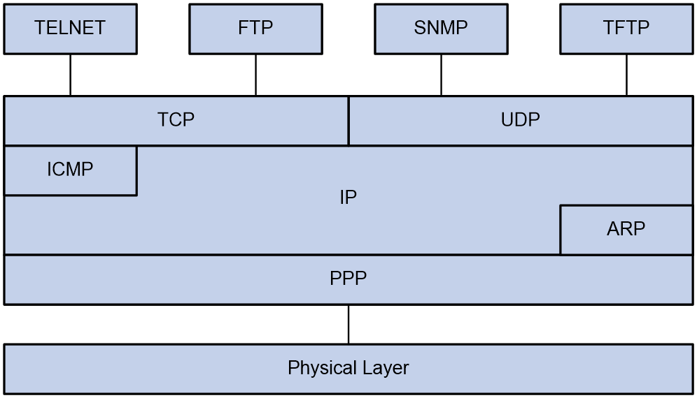
PPP mainly contains the following protocol families:
· Link Control Protocol (LCP) family—Mainly used to establish, terminate, and monitor a PPP data link.
· Network Control Protocol (NCP) family—Mainly used to negotiate the format and type of data packets transmitted on a data link.
· PPP extension protocol family—Mainly used to provide further support for PPP functionality. For example, PPP provides authentication protocols CHAP and PAP for network security.
Frame format of PPP packet encapsulation
The PPP packet encapsulation format is as shown in Figure 2.
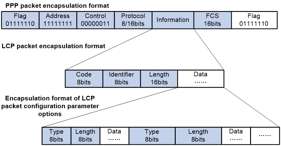
The fields are described as follows:
· Flag field
The flag field identifies the start and end of a physical frame, and this byte is 0x7E.
· Address field
The address field can uniquely identify the peer end. The PPP protocol is used on point-to-point links, so two communicating devices interconnected by using the PPP protocol do not need to know each other's data link layer address. According to the protocol, the byte is filled with the all-1 broadcast address, which has no practical meaning for the PPP protocol.
· Control field
The default value for this field is 0x03, indicating unnumbered frame. By default, PPP does not use sequence numbers and acknowledgment mechanism to achieve reliable transmission.
The address and control fields together identify this packet as a PPP packet. Therefore, the PPP packet header is FF03.
· Protocol field
The protocol field distinguishes the packet types carried in the information field of PPP frames.
The contents of the protocol field must conform to the provisions of the address extension mechanism provided by ISO 3309. The mechanism specifies that the contents filled in the protocol field must be odd, which means the lowest significant bit in the lowest significant byte should be 1 and the lowest significant bit in the highest significant byte should be 0.
If the protocol field of the PPP frame sent by the sender does not meet the preceding requirements, the receiver will consider this frame unrecognizable. The receiver sends a Protocol-Reject packet to the sender, including the rejected protocol number at the end of the packet.
Table 1 Common protocol codes
|
Protocol code |
Protocol type |
|
0021 |
Internet Protocol |
|
002b |
Novell IPX |
|
002d |
Van Jacobson Compressed TCP/IP |
|
002f |
Van Jacobson Uncompressed TCP/IP |
|
8021 |
Internet Protocol Control Protocol |
|
802b |
Novell IPX Control Protocol |
|
8031 |
Bridging NC |
|
C021 |
Link Control Protocol |
|
C023 |
Password Authentication Protocol |
|
C223 |
Challenge Handshake Authentication Protocol |
· Information field
The maximum length of the information field is 1500 bytes, including the content of the padding field. The maximum length of the information field is called the Maximum Receive Unit (MRU). The default MRU is 1500 bytes. In actual applications, you can negotiate the MRU as needed.
If the information field length is insufficient, it can be padded, which is not required. If padding is applied, both ends of the communication must be able to distinguish between the padded information and the actual information that needs to be transmitted to communicate properly.
· FCS field
The main purpose of the FCS field is to check the correctness of PPP frame transmission.
Introducing some transmission assurance mechanisms into the frame will introduce more overhead, which might increase the latency of application layer interaction.
Frame format of LCP packet encapsulation
The LCP packet encapsulation format is as shown in Figure 2.
During the link establishment phase, the PPP protocol establishes and negotiates the link through LCP packets. At this time, an LCP packet is encapsulated as the payload of PPP in the information field of the PPP frame, and the protocol field of the PPP frame is padded with a fixed value of 0xC021.
During the entire process of link establishment, the content of the information field is variable, including many types of packets. These packets also need to be distinguished through the corresponding fields.
· Code field
The code field is one byte long and is mainly used to identify the type of LCP data packets.
During the link establishment phase, the receiver receives the LCP data packets. When the value of their code field is invalid, the receiver will send a Code-Reject packet to the peer end.
Table 2 Common code values
|
Code value |
Packet type |
|
0x01 |
Configure-Request |
|
0x02 |
Configure-Ack |
|
0x03 |
Configure-Nak |
|
0x04 |
Configure-Reject |
|
0x05 |
Terminate-Request |
|
0x06 |
Terminate-Ack |
|
0x07 |
Code-Reject |
|
0x08 |
Protocol-Reject |
|
0x09 |
Echo-Request |
|
0x0A |
Echo-Reply |
|
0x0B |
Discard-Request |
|
0x0C |
Reserved |
· Identifier field
The identifier field is 1 byte long, and it is used to match requests and replies. When the identifier field value of a packet is illegal, the packet will be dropped.
Typically, the ID of a Configure-Request packet starts at 0x01 and increases gradually by 1. When the peer end receives the Configure-Request packet, the ID in the response packet must be the same as the ID in the received packet no matter what kind of packet is used to respond.
· Length field
The value of the length field is the total number of bytes in the LCP packet. It is the sum of the lengths of the four fields: code, identifier, length, and data fields.
Bytes beyond the number indicated by the length field will be treated as padded bytes and ignored, and the content of the length field cannot exceed the MRU.
· Data field
The data field contains the content of the negotiation packet, including the following fields.
¡ The type field indicates the negotiation option type.
¡ The length field indicates the negotiation option length, which is the total length of the data field, including type, length, and data.
¡ The data field contains details of the negotiation option.
Table 3 Common negotiation type values in the type field
|
Negotiation type value |
Negotiation packet type |
|
0x01 |
Maximum-Receive-Unit |
|
0x02 |
Async-Control-Character-Map |
|
0x03 |
Authentication-Protocol |
|
0x04 |
Quality-Protocol |
|
0x05 |
Magic-Number |
|
0x06 |
RESERVED |
|
0x07 |
Protocol-Field-Compression |
|
0x08 |
Address-and-Control-Field-Compression |
PPP link establishment process
Basic process
Figure 3 shows the PPP link establishment process.
Figure 3 PPP link establishment process
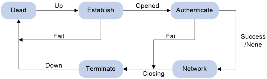
1. Initially, PPP is in Link Dead phase. After the physical layer goes up, PPP enters the Link Establishment phase (Establish).
2. In the Link Establishment phase, the LCP negotiation is performed. The LCP configuration options include Authentication-Protocol, Async-Control-Character-Map (ACCM), Maximum-Receive-Unit (MRU), Magic-Number, Protocol-Field-Compression (PFC), Address-and-Control-Field-Compression (ACFC), and MP.
¡ If the negotiation fails, LCP reports a Fail event, and PPP returns to the Dead phase.
¡ If the negotiation succeeds, LCP enters the Opened state and reports an Up event, indicating that the underlying layer link has been established. At this time, the PPP link is not established for the network layer, and network layer packets cannot be transmitted over the link.
3. If authentication is configured, the PPP link enters the Authentication phase, where PAP, CHAP, MS-CHAP, or MS-CHAP-V2 authentication is performed.
¡ If the client fails to pass the authentication, LCP reports a Fail event and enters the Link Termination phase. In this phase, the link is torn down and LCP goes down.
¡ If the client passes the authentication, LCP reports a Success event.
4. If a network layer protocol is configured, the PPP link enters the Network-Layer Protocol phase for NCP negotiation, such as IPCP negotiation and IPv6CP negotiation.
¡ If the NCP negotiation succeeds, the link goes up and becomes ready to carry negotiated network-layer protocol packets.
¡ If the NCP negotiation fails, NCP reports a Down event and enters the Link Termination phase.
If the interface is configured with an IP address, the IPCP negotiation is performed. IPCP configuration options include IP addresses and DNS server IP addresses. After the IPCP negotiation succeeds, the link can carry IP packets.
5. After the NCP negotiation is performed, the PPP link remains active until either of the following events occurs:
¡ Explicit LCP or NCP frames close the link.
¡ Some external events take place (for example, the intervention of a user).
Dead phase (physical-layer not ready phase)
The dead phase is also known as the physical-layer not ready phase. A PPP link necessarily begins and ends with this phase.
When both ends of the communication detect the physical line activation (usually the carrier signal on the link), they will transition from the dead phase to link establishment phase.
The link will return to the physical-layer not ready phase after it is disconnected.
Establish phase (link establishment phase)
During the establish phase, a PPP link undergoes LCP negotiation. The negotiation content includes options such as single-link PPP (SP) or multilink PPP (MP), maximum receive unit (MRU), authentication method, and magic number. When the exchange of configuration packets is completed, the link will proceed to the next phase.
|
|
NOTE: After the link is established, the next phase can be selected based on the configuration of the devices at both ends of the link. The next phase can be either the authentication phase or the network layer protocol phase. This selection depends on the configuration made by the user on the devices at both ends of the link. |
During the establish phase, the LCP state machine will undergo the following changes.
· When the link is in physical-layer not ready phase, the LCP state machine is in the Initial or Starting state. When the physical layer detects that the link is available, it will send an Up event to the link layer. Upon receiving this event, the link layer will change the LCP state machine from the current state to Request-Sent state. Then, LCP will take corresponding actions to send a Configure-Request packet to configure the data link.
· If the local device receives the Configure-Ack packet first, the LCP state machine will change from Request-Sent state to Ack-Received state. After the local end sends the Configure-Ack packet to the peer end, the LCP state machine will change from Ack-Received state to Open state.
· If the local device sends a Configure-Ack packet to the peer end first, the LCP state machine will change from Request-Sent state to Ack-Sent state. After the local end receives the Configure-Ack packet from the peer end, the LCP state machine will change from Ack-Sent state to Open state.
· Once the LCP state machine enters Open state, the link completes the current negotiation phase and proceeds to the next phase.
Authenticate phase (authentication phase)
By default, a PPP link does not perform authentication. If authentication is required, the authentication protocol must be specified during the link establishment phase.
PPP provides two authentication methods: Password Authentication Protocol (PAP) and Challenge Handshake Authentication Protocol (CHAP).
|
|
NOTE: PPP authentication methods include one-way authentication and two-way authentication. · One-way authentication refers to one end acting as the authenticator and the other end as the authenticatee. · Two-way authentication is a simple overlay of one-way authentication, where both ends act as both the authenticator and the authenticatee. |
PAP authentication process
PAP authentication is two-way handshake authentication, and uses simple passwords.
The process of PAP authentication is shown in Figure 4.
Figure 4 PAP authentication process

1. The authenticatee sends the local username and password to the authenticator.
2. The authenticator checks the local user table to identify whether the authenticatee's username exists.
¡ If yes, the authenticator identifies whether the password is correct.
- If the password is correct, the authentication will succeed.
- If the password is incorrect, the authentication will fail.
¡ If not, the authentication will fail.
Frame format of a PAP authentication packet
A PAP packet is encapsulated with a protocol field of 0xC023 in the information field of the PPP data link layer frame. The frame format of a PAP packet is as shown in Figure 5.
Figure 5 Frame format of a PAP authentication packet
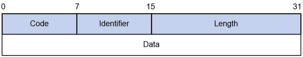
In the frame format of a PAP authentication packet, the meaning of each field is described in Table 4.
Table 4 Fields in the frame format of a PAP authentication packet
|
Field |
Length (bytes) |
|
Code |
1 |
|
Identifier |
1 |
|
Length |
2 |
|
Data |
0 or more bytes |
CHAP authentication process
CHAP authentication is a three-way handshake authentication protocol. CHAP transmits only the username rather than the user password over the network, so it is more secure than PAP.
The authentication process of CHAP is as shown in Figure 6.
Figure 6 CHAP authentication process

The CHAP one-way authentication process supports two cases: the authenticator has configured a username and the authenticator has not configured a username. As a best practice, use the method of configuring the username on the authenticator, so that the username of the authenticator can be confirmed.
· Authentication process when the authenticator has configured a username
a. The authenticator initiates the authentication request, constructs a packet containing a random number, and at the same time sends the local username to the authenticatee. (Challenge.)
b. When the authenticatee receives the authentication request from the authenticator, the authenticatee first identifies whether a CHAP password is configured on the local interface.
- If the interface is configured with a CHAP password, the authenticatee uses the hash algorithm to calculate a hash value based on the packet ID, CHAP password, and random number in the packet. Then, the authenticatee sends the obtained hash value and the username of the authenticatee back to the authenticator. (Response.)
- If the interface is not configured with a CHAP password, the authenticatee searches for the password corresponding to the user in the local user table based on the authenticator username in the packet. The authenticatee uses the hash algorithm to calculate a hash value based on the packet ID, user password, and the random number in the packet, and sends the obtained hash value and the username of the authenticatee back to the authenticator. (Response).
c. The authenticator first looks up the password corresponding to the user in the local end based on the username of the authenticatee in the received packet. Then, the authenticator uses the hash algorithm to calculate a hash value based on the packet ID, the password of the authenticatee, and the random number in the Challenge packet, and compares the obtained hash value with the hash value in the Response packet. If the comparison result is consistent, the authentication succeeds. If the comparison result is inconsistent, the authentication fails.
· Authentication process when the authenticator has not configured a username
d. The authenticator initiates an authentication request, and sends a packet containing a random number to the authenticatee. (Challenge.)
e. After receiving the authentication request from the authenticator, the authenticatee uses the hash algorithm to calculate a hash value based on the packet ID, configured CHAP password, and random number in the packet. Then, the authenticatee sends the obtained hash value and its own username back to the authenticator. (Response).
f. The authenticator first looks up the password corresponding to the username of the authenticatee in the local send based on the received packet. Then, the authenticator calculates the hash value by using a hash algorithm based on the packet ID, the password of the authenticatee, and the random number in the packet, and compares it with the hash value in the Response packet. If the comparison result is consistent, the authentication succeeds. If the comparison result is inconsistent, the authentication fails.
Frame format of a CHAP authentication packet
A CHAP packet is encapsulated with a protocol field of 0xC223 in the information field of the PPP data link layer frame. The frame format of a CHAP packet is as shown in Figure 7.
Figure 7 Frame format of a CHAP authentication packet

In the frame format of a CHAP authentication packet, the meaning of each field is described in Table 5.
Table 5 Fields in the frame format of a CHAP authentication packet
|
Field |
Length (bytes) |
|
Code |
1 |
|
Identifier |
1 |
|
Length |
2 |
|
Data |
0 or more bytes |
|
|
NOTE: The differences between CHAP and PAP authentication methods are as follows: · PAP authentication involves sending a simple password on the link. After the PPP link is established, the authenticatee continuously sends the username and password on the link until the authentication process ends. Therefore, PAP authentication is not very secure. When the security requirements are not high in practical applications, you can use PAP authentication to establish a PPP connection. · In CHAP authentication, the authentication protocol is a three-way handshake authentication protocol. CHAP transmits only the username rather than the user password over the network, so it is more secure than PAP. When the security requirements are high in practical applications, you can use CHAP authentication to establish a PPP connection. |
Network phase (network layer protocol phase)
After PPP completes the previous phase, PPP selects and configures a network layer protocol and negotiates network layer parameters through NCP negotiation. Each NCP protocol can be enabled and disabled at any time. When the state machine of an NCP protocol becomes Open, PPP can begin network layer data transmission on the link.
Terminate phase (link termination phase)
PPP can terminate the link at any time. When the carrier is lost, authentication fails, or the administrator manually closes the link, the link will be terminated.
PPP authentication
PPP supports the following authentication methods:
PAP
PAP is a two-way handshake authentication protocol using the username and password. PAP sends username/password pairs in plain text over the network. If authentication packets are intercepted in transit, network security might be threatened. For this reason, it is suitable only for low-security environments.
CHAP
CHAP is a three-way handshake authentication protocol.
CHAP transmits usernames but not passwords over the network. It transmits the result calculated from the password and random packet ID by using the MD5 algorithm. CHAP is more secure than PAP.
MS-CHAP
MS-CHAP is a three-way handshake authentication protocol. MS-CHAP differs from CHAP in that MS-CHAP provides authentication retry. If the peer fails authentication, it is allowed to retransmit authentication information to the authenticator for reauthentication. The authenticator allows a peer to retransmit a maximum of three times.
MS-CHAP-V2
MS-CHAP-V2 is a three-way handshake authentication protocol.
MS-CHAP-V2 differs from CHAP as follows:
· MS-CHAP-V2 provides two-way authentication by piggybacking a peer challenge on the Response packet and an authenticator response on the Acknowledge packet.
· MS-CHAP-V2 supports authentication retry. If the peer fails authentication, it is allowed to retransmit authentication information to the authenticator for reauthentication. The authenticator allows a peer to retransmit a maximum of three times.
· MS-CHAP-V2 supports password change. If the peer fails authentication because of an expired password, it will send the new password entered by the user to the authenticator for reauthentication.
PPP for IPv4
On IPv4 networks, PPP negotiates the IP address and DNS server address during IPCP negotiation.
IP address negotiation
IP address negotiation enables one end to assign an IP address to the other.
An interface can act as a client or a server during IP address negotiation:
· Client—Obtains an IP address from the server. Use the client mode when the device accesses the Internet through an ISP.
· Server—Assigns an IP address to the client. Before you configure the IP address of the server, you must perform one of the following tasks:
¡ Configure a local address pool and associate the pool with the ISP domain.
¡ Specify an IP address pool for the client on the interface.
When IP address negotiation is enabled on a client, the server selects an IP address for the client in the following sequence:
1. If the AAA server configures an IP address or address pool for the client, the server selects that IP address or an IP address from the pool. The IP address or address pool is configured on the AAA server instead of the PPP server. For information about AAA, see BRAS Services Configuration Guide.
2. If an address pool is associated with the ISP domain used during client authentication, the server selects an IP address from the pool.
3. If an IP address pool is specified for the client on the interface of the server, the server selects that IP address or an IP address from that pool.
DNS server address negotiation
IPCP negotiation can determine the DNS server IP address. The device can only act as the server to assign the DNS server IP address to the clients.
PPP for IPv6
On IPv6 networks, PPP negotiates only the IPv6 interface identifier instead of the IPv6 address and IPv6 DNS server address during IPv6CP negotiation. PPP users have to obtain IPv6 global unicast addresses and IPv6 DNS server addresses by using ND or DHCPv6 protocols.
IPv6 address assignment
A host can get an IPv6 global unicast address through the following methods:
· NDRA—The host obtains an IPv6 prefix in an RA message. The host then generates an IPv6 global unicast address by combining the IPv6 prefix and the negotiated IPv6 interface identifier. The IPv6 prefix in the RA message is determined in the following sequence:
a. IPv6 prefix authorized by an AAA server through the Framed-IPv6-Prefix attribute.
b. IPv6 prefix authorized in an ISP domain.
c. Prefix in the ND prefix pool authorized in an ISP domain.
d. Prefix in the 128-bit IPv6 global unicast address authorized by an AAA server through the Framed-IPv6-Address attribute. If an interface identifier has been authorized by an AAA server through the Framed-Interface-Id attribute, skip this step and go to step f.
e. Prefix in the 128-bit IPv6 global unicast address authorized by using the authorization-attribute ipv6 command in local user view. If an interface identifier has been authorized by an AAA server through the Framed-Interface-Id attribute, skip this step and go to step f.
f. RA prefix configured on the interface.
g. Prefix in the IPv6 global unicast address configured on the interface.
|
|
NOTE: The method of authorizing an ND prefix pool in an ISP domain applies to the scenario of one prefix per user. In this scenario, each user has an exclusive IPv6 prefix. Other methods apply to the prefix sharing scenario, in which multiple users can share the same IPv6 prefix. |
The negotiated IPv6 interface identifiers are determined in the following sequence:
a. Interface identifier authorized by an AAA server through the Framed-Interface-Id attribute.
b. Interface identifier in the 128-bit IPv6 global unicast address authorized by an AAA server through the Framed-IPv6-Address attribute. If an IPv6 prefix has been authorized by an AAA server through the Framed-IPv6-Prefix attribute, skip this step and go to step d.
c. Interface identifier in the 128-bit IPv6 global unicast address authorized by using the authorization-attribute ipv6 command in local user view. If an IPv6 prefix has been authorized by an AAA server through the Framed-IPv6-Prefix attribute, skip this step and go to step d.
d. Interface identifier automatically generated for the PPP user when the ipv6cp assign-interface-id command is executed in an ISP domain.
e. Non-zero interface identifier that is carried by the user and does not conflict with any other interface identifier.
f. Interface identifier automatically generated for the PPP user when the interface identifier carried by the user is invalid.
The ND prefix pool authorized by AAA and the IA_NA method are mutually exclusive. For information about the ND protocol, see Layer 3—IP Services Configuration Guide.
· DHCPv6 (IA_NA)—The host requests an IPv6 global unicast address through DHCPv6. The server assigns an IPv6 address to the host from the address pool authorized by AAA. If no AAA-authorized address pool exists, DHCPv6 uses the address pool that matches the server's IPv6 address to assign an IPv6 address to the host. For information about DHCPv6, see BRAS Services Configuration Guide.
After an IPv6 address pool is authorized to users, IA_NA also supports authorizing the specified 128-bit IPv6 global unicast addresses to PPP users through the following methods:
¡ Authorizing 128-bit IPv6 global unicast addresses by an AAA server through the Framed-IPv6-Address attribute.
¡ Authorizing 128-bit IPv6 global unicast addresses by using the authorization-attribute ipv6 command in local user view.
Make sure the 128-bit IPv6 global unicast addresses authorized by using the two methods above are within the authorized IPv6 address pool. Otherwise, the 128-bit IPv6 global unicast addresses authorized by using the two methods above are not used, and IPv6 addresses in the IPv6 address pool are randomly allocated to users.
· DHCPv6 (IA_PD)—A client-side device requests prefixes through DHCPv6 and assigns them to downstream hosts. The hosts then use the prefixes to generate global IPv6 addresses. This method uses the same principle of selecting address pools as the DHCPv6 (IA_NA) method.
The device can assign a host an IPv6 address in either of the following ways:
· When the host connects to the device directly or through a bridge device, the device can use the NDRA method or the IA_NA method.
· When the host accesses the device through a router, the device can use the IA_PD method to assign an IPv6 prefix to the router. The router assigns the prefix to the host to generate an IPv6 global unicast address.
· You can use the NDRA+IA_PD combination or the IA_NA+IA_PD combination as needed to meet address assignment requirements in different scenarios.
IPv6 DNS server address assignment
On IPv6 networks, two methods are available for the IPv6 DNS server address assignment:
· The client obtains the IPv6 DNS server address from the DNS server options carried in ND RA packets. The DNS server option carried in RA packets can be authorized by AAA or configured by using the ipv6 nd ra dns server command on an interface. If both the IPv6 DNS server option authorized by AAA and the IPv6 DNS server option configured on an interface are available, the RA packets carry both options, with the AAA-authorized one in the front. If the two options conflict, the AAA-authorized one applies. For more information about the ipv6 nd ra dns server command, see Layer 3—IP Services Command Reference.
· The DHCPv6 client requests an IPv6 DNS server address from the DHCPv6 server.
Protocols and standards
RFC 1661: The Point-to-Point Protocol (PPP)
PPP tasks at a glance
To configure PPP, perform the following tasks:
¡ Restoring the default settings for the VT interface
In a PPPoE or L2TP network, you must configure VT interfaces. For more information about PPPoE and L2TP, see BRAS Services Configuration Guide.
2. Configuring PPP authentication
Choose one of the following tasks:
¡ Configuring PAP authentication
¡ Configuring CHAP authentication
¡ Configuring MS-CHAP or MS-CHAP-V2 authentication
Configure PPP authentication for high-security environments.
3. (Optional.) Configuring the polling feature
4. (Optional.) Configuring a VT interface not to perform keepalive detection when the uplink traffic of PPP users is updated
5. (Optional.) Enabling fast reply for keepalive packets
6. (Optional.) Configuring PPP negotiation
¡ Configuring the PPP negotiation timeout time
¡ Configuring IPv4 address negotiation on the client
¡ Configuring IPv4 address negotiation on the server
¡ Configuring IPv6 address negotiation on the server
¡ Configuring DNS server IP address negotiation on the client
¡ Configuring DNS server IP address negotiation on the server
7. (Optional.) Configuring magic number check for PPP
8. (Optional.) Enabling MRU check for PPP packets
9. (Optional.) Specifying that PPP users cannot come online successfully if the online requests do not carry usernames
10. (Optional.) Enabling PPP user blocking
¡ Enabling per-username PPP user blocking
¡ Configuration per-MAC PPP user blocking
11. (Optional.) Setting the online PPP session count alarm thresholds on the device
Configuring a VT interface
Creating a VT interface
About VT interfaces
Virtual-template (VT) interfaces are logical interfaces manually created on devices. A VT interface can implement the functionality of a physical WAN interface with PPP encapsulation enabled. For a VT interface to operate normally, you must bind it to a physical interface.
In PPPoE and L2TP applications, you can use VT interfaces to implement related functions of PPP. For more information about PPPoE and L2TP, see "Configuring PPPoE" and "Configuring L2TP."
Procedure
1. Enter system view.
system-view
2. Create a VT interface and enter its view.
interface virtual-template number
3. (Optional.) Set the interface description.
description text
By default, the description of a VT interface is interface name Interface, for example, Virtual-Template1 Interface.
4. (Optional.) Set the MTU size of the interface.
mtu size
By default, the MTU of a VT interface varies by interface type.
5. (Optional.) Set the expected bandwidth of the VT interface.
bandwidth bandwidth-value
By default, the expected bandwidth (in kbps) is the interface baud rate divided by 1000.
Restoring the default settings for the VT interface
Restrictions and guidelines
The default command might interrupt ongoing network services. Make sure you are fully aware of the impact of this command when you execute it on a live network.
The default command might fail to restore the default settings for some commands for reasons such as command dependencies or system restrictions. Use the display this command in interface view to identify these commands. Use the undo forms of these commands or follow the command reference to individually restore their default settings. If your restoration attempt still fails, follow the error message instructions to resolve the problem.
Procedure
1. Enter system view.
system-view
2. Enter VT interface view.
interface virtual-template number
3. Restore the default settings for the interface.
default
Configuring PPP authentication
About PPP authentication
You can configure several authentication modes simultaneously. In LCP negotiation, the authenticator negotiates with the peer in the sequence of configured authentication modes until the LCP negotiation succeeds. If the response packet from the peer carries a recommended authentication mode, the authenticator directly uses the authentication mode if it finds the mode configured.
Configuring PAP authentication
Restrictions and guidelines for PAP authentication
For local AAA authentication, the username and password of the peer must be configured on the authenticator.
For remote AAA authentication, the username and password of the peer must be configured on the remote AAA server.
The username and password configured for the peer must be the same as those configured on the peer by using the ppp pap local-user command.
Configuring the authenticator
1. Enter system view.
system-view
2. Enter interface view.
interface virtual-template interface-number
3. Configure the authenticator to authenticate the peer by using PAP.
ppp authentication-mode pap [ domain { isp-name | default enable isp-name } ]
By default, PPP authentication is disabled.
4. Configure local or remote AAA authentication.
For information about AAA, see BRAS Services Configuration Guide.
Configuring the peer
1. Enter system view.
system-view
2. Enter interface view.
interface virtual-ppp interface-number
3. Configure the PAP username and password sent from the peer to the authenticator when the peer is authenticated by the authenticator by using PAP.
ppp pap local-user username password { cipher | simple } string
By default, when being authenticated by the authenticator by using PAP, the peer sends null username and password to the authenticator.
For security purposes, the password specified in plaintext form and ciphertext form will be stored in encrypted form.
Configuring CHAP authentication
Restrictions and guidelines
For local AAA authentication, the username and password of the peer must be configured on the authenticator.
For remote AAA authentication, the username and password of the peer must be configured on the remote AAA server.
The username and password configured for the peer must meet the following requirements:
· The username configured for the peer must be the same as that configured on the peer by using the ppp chap user command.
· The password configured for the peer must be the same as that configured on the peer by using the ppp chap password command.
Configuring the authenticator
1. Enter system view.
system-view
2. Enter interface view.
interface virtual-template interface-number
3. Configure the authenticator to authenticate the peer by using CHAP.
ppp authentication-mode chap [ domain { isp-name | default enable isp-name } ]
By default, PPP authentication is disabled.
4. Configure local or remote AAA authentication.
For information about AAA, see BRAS Services Configuration Guide.
Configuring the peer
1. Enter system view.
system-view
2. Enter interface view.
interface virtual-ppp interface-number
3. Configure a username for the CHAP peer.
ppp chap user username
The default setting is null.
4. Set the CHAP authentication password.
ppp chap password { cipher | simple } string
The default setting is null.
For security purposes, the password specified in plaintext form and ciphertext form will be stored in encrypted form.
Configuring MS-CHAP or MS-CHAP-V2 authentication
Restrictions and guidelines for MS-CHAP or MS-CHAP-V2 authentication
The device can only act as an authenticator for MS-CHAP or MS-CHAP-V2 authentication.
L2TP supports only MS-CHAP authentication.
MS-CHAP-V2 authentication supports password change only when using RADIUS.
As a best practice, do not set the authentication method for PPP users to none when MS-CHAP-V2 authentication is used.
For local AAA authentication, the username and password of the peer must be configured on the authenticator. For remote AAA authentication, the username and password of the peer must be configured on the remote AAA server. The username and password of the peer configured on the authenticator or remote AAA server must be the same as those configured on the peer.
Procedure
1. Enter system view.
system-view
2. Enter interface view.
interface virtual-template interface-number
3. Configure the authenticator to authenticate the peer by using MS-CHAP or MS-CHAP-V2.
ppp authentication-mode { ms-chap | ms-chap-v2 } [ domain { isp-name | default enable isp-name } ]
By default, PPP authentication is disabled.
4. Configure local or remote AAA authentication.
For information about AAA, see BRAS Services Configuration Guide.
Configuring the polling feature
About this task
The polling feature checks PPP link state.
On an interface that uses PPP encapsulation, the link layer sends keepalive packets at keepalive intervals to detect the availability of the peer. If the interface has received no response to keepalive packets when the keepalive retry limit is reached, it determines that the link has failed and reports a link layer down event.
To set the keepalive retry limit, use the timer-hold retry command.
The value 0 disables an interface from sending keepalive packets. In this case, the interface can respond to keepalive packets from the peer.
Restrictions and guidelines
On a slow link, increase the keepalive interval to prevent false shutdown of the interface. This situation might occur when keepalive packets are delayed because a large packet is being transmitted on the link.
The keepalive interval must be smaller than the negotiation timeout time.
Procedure
1. Enter system view.
system-view
2. Enter interface view.
interface interface-type interface-number
3. Set the keepalive interval.
timer-hold seconds
By default, the keepalive interval is 10 seconds for a POS or serial interface and 60 seconds for a virtual-PPP interface.
4. Set the keepalive retry limit.
timer-hold retry retries
By default, the keepalive retry limit is 5 for a POS or serial interface and 3 for a virtual-PPP interface.
Configuring a VT interface not to perform keepalive detection when the uplink traffic of PPP users is updated
About this task
If the configured keepalive interval (timer-hold seconds) or keepalive retry limit (timer-hold retry retries) is small, users might go offline because the interface cannot receive keepalive packets from the peer when congestion occurs in the network. To prevent keepalive packets from making the congestion deteriorate or causing users to frequently go offline, configure this feature.
With this feature configured, if the uplink traffic of PPP users is updated within a keepalive interval, the keepalive timer is reset, and online detection will not be performed. Otherwise, keepalive packets are sent to detect online users after the keepalive interval expires. For example, suppose you set the keepalive interval to 10 seconds by using the timer-hold command. If uplink traffic of PPP users is updated at the 5th second, the keepalive timer is reset. In this way, the sending of keepalive packets is delayed. If uplink traffic is updated within the next keepalive interval (10 seconds), the keepalive timer is reset again.
Restrictions and guidelines
To balance the overall device performance and ensure that the device operates at the best performance, the device uses the periodical statistics collection mechanism to collect user traffic update conditions. When a large number of users are online, you can configure the device to reset the keepalive timer and not to perform keepalive detection if the uplink traffic of a user is updated within one keepalive interval. In this case, as a best practice, increase the keepalive interval by using the timer-hold seconds command. If you do not do that, when the traffic of some users is updated within one keepalive interval, the device might fail to timely collect traffic update conditions of these users. As a result, the device considers that the traffic is not updated for these users, and sends detection packets to these users.
Procedure
1. Enter system view.
system-view
2. Enter VT interface view.
interface virtual-template number
3. Configure the VT interface not to perform keepalive detection when the uplink traffic of PPP users is updated.
ppp keepalive datacheck
By default, keepalive packets are sent to detect online users after the keepalive interval expires no matter whether the uplink traffic of PPP users is updated within a keepalive interval.
Enabling fast reply for keepalive packets
About this task
This feature allows the hardware to automatically identify and reply to incoming keepalive requests, which can prevent DDoS attacks.
Restrictions and guidelines
In standard system operating mode, this feature is available only for the following cards and takes effect only on keepalive packets received on Ethernet links.
Table 6 Card information
|
Card category |
Cards |
|
CSPEX |
CSPEX-1304S, CSPEX-1404S, CSPEX-1504S |
In SDN-WAN system operating mode, this feature is not supported.
Procedure
1. Enter system view.
system-view
2. Enable fast reply for keepalive packets.
In standalone mode:
ppp keepalive fast-reply enable slot slot-number
In IRF mode:
ppp keepalive fast-reply enable chassis chassis-number slot slot-number
By default, fast reply is enabled for keepalive packets.
Configuring PPP negotiation
Configuring the PPP negotiation timeout time
About this task
The device starts the PPP negotiation timeout timer after sending a packet. If no response is received before the timer expires, the device sends the packet again.
Restrictions and guidelines
If two ends of a PPP link vary greatly in the LCP negotiation packet processing rate, configure the delay timer on the end with a higher processing rate. The LCP negotiation delay timer prevents frequent LCP negotiation packet retransmission. After the physical layer comes up, PPP starts LCP negotiation when the delay timer expires. If PPP receives LCP negotiation packets before the delay timer expires, it starts LCP negotiation immediately.
Procedure
1. Enter system view.
system-view
2. Enter interface view.
interface interface-type interface-number
3. (Optional.) Configure the LCP negotiation delay timer.
ppp lcp delay milliseconds
By default, PPP starts LCP negotiation after the physical layer comes up.
4. Configure the negotiation timeout time.
ppp timer negotiate seconds
The default setting is 3 seconds.
Configuring IPv4 address negotiation on the client
1. Enter system view.
system-view
2. Enter interface view.
interface virtual-ppp interface-number
3. Enable IP address negotiation.
ip address ppp-negotiate
By default, IP address negotiation is not enabled.
If you execute this command and the ip address command multiple times, the most recent configuration takes effect. For more information about the ip address command, see Layer 3—IP Services Command Reference.
Configuring IPv4 address negotiation on the server
About this task
Configure the server to assign an IP address to a client by using the following methods:
· Method 1: Specify an address pool on the server interface.
· Method 2: Associate an address pool with an ISP domain.
· Method 3: Authorize an IP address to a client by using the AAA server.
Restrictions and guidelines for IP address negotiation on the server
For clients requiring no authentication, you can use method 1.
For clients requiring authentication, you can use one or more of the three methods. When multiple methods are configured, method 3 takes precedence over method 2, and method 2 takes precedence over method 1.
When you use method 4, enable DHCP on the AAA server by using the dhcp enable command and authorize an IP address to the client. For more information about the dhcp enable command, see BRAS Services Command Reference.
Specifying an IP address pool on the server interface
1. Enter system view.
system-view
2. Configure DHCP.
¡ If the server acts as a DHCP server, perform the following tasks:
- Configure the DHCP server.
- Configure an IP address pool on the server.
¡ If the server acts as a DHCP relay agent, perform the following tasks:
- Configure the DHCP relay agent on the server.
- Configure an IP address pool on the remote DHCP server.
- Enable the DHCP relay agent to record relay entries.
- Configure a DHCP relay address pool.
For information about configuring a DHCP server and a DHCP relay agent, see BRAS Services Configuration Guide.
3. Enter interface view.
interface virtual-template interface-number
4. Configure the interface to assign an IP address from the configured IP address pool to the peer.
remote address pool pool-name
By default, an interface does not assign an IP address to the peer.
5. (Optional.) Configure the method of generating DHCP client IDs when PPP users act as DHCP clients.
remote address dhcp client-identifier { { callingnum | username } [ session-info ] | session-info }
By default, the method of generating DHCP client IDs when PPP users act as DHCP clients is not configured.
When DHCP client IDs are generated based on PPP usernames, make sure different users use different PPP usernames to come online.
6. Configure an IP address for the interface.
ip address ip-address
By default, no IP address is configured on an interface.
Associating an IP address pool with an ISP domain
1. Enter system view.
system-view
2. Configure DHCP.
¡ If the server acts as a DHCP server, perform the following tasks:
- Configure the DHCP server.
- Configure an IP address pool on the server.
¡ If the server acts as a DHCP relay agent, perform the following tasks:
- Configure the DHCP relay agent on the server.
- Configure an IP address pool on the remote DHCP server.
- Enable the DHCP relay agent to record relay entries.
- Configure a DHCP relay address pool.
For information about configuring a DHCP server and a DHCP relay agent, see BRAS Services Configuration Guide.
3. Enter ISP domain view.
domain name isp-name
4. Associate the ISP domain with the configured IP address pool or DHCP relay address pool for address assignment.
authorization-attribute ip-pool pool-name
By default, no IP address pool or DHCP relay address pool is associated.
For more information about this command, see BRAS Services Command Reference.
5. Return to system view.
quit
6. Enter interface view.
interface interface-type interface-number
7. (Optional.) Configure the method of generating DHCP client IDs when PPP users act as DHCP clients.
remote address dhcp client-identifier { { callingnum | username } [ session-info ] | session-info }
By default, the method of generating DHCP client IDs when PPP users act as DHCP clients is not configured.
When DHCP client IDs are generated based on PPP usernames, make sure different users use different PPP usernames to come online.
8. Configure an IP address for the interface.
ip address ip-address
By default, no IP address is configured on an interface.
Configuring IPv6 address negotiation on the server
Assigning an IPv6 address by using the NDRA method
1. Enter VT interface view.
interface virtual-template interface-number
2. Enable the interface to advertise RA messages.
undo ipv6 nd ra halt
3. Configure the prefix information in RA messages on the interface.
ipv6 nd ra prefix { ipv6-prefix prefix-length | ipv6-prefix/prefix-length } [ valid-lifetime preferred-lifetime [ no-autoconfig | off-link ] * ]
The IPv6 prefix in the RA message is determined in the following sequence:
¡ IPv6 prefix authorized by AAA.
¡ Prefix in the ND prefix pool authorized by AAA.
¡ RA prefix configured on the interface.
¡ Prefix of the IPv6 global unicast address configured on the interface.
If the ipv6 nd ra prefix command is executed on both a user access interface and the VT interface bound to the interface, the command takes effect only on the VT interface.
4. Set the other stateful configuration flag (O) to 1 in RA advertisements to be sent.
ipv6 nd autoconfig other-flag
You can also execute this command in ISP domain view. Execute this command in at least one of ISP domain view and interface view.
5. Return to system view.
quit
6. Enter user access interface view.
interface interface-type interface-number
7. Configure the interface to automatically generate a link-local address.
ipv6 address auto link-local
8. Enable the interface to advertise RA messages.
undo ipv6 nd ra halt
9. Enable the DHCPv6 server.
ipv6 dhcp select server
10. Return to system view.
quit
11. Create an ISP domain and enter its view.
domain name isp-name
12. Configure an IPv6 prefix authorized to the user in the ISP domain.
authorization-attribute ipv6-prefix ipv6-prefix prefix-length
Assigning an IPv6 address by using the IA_NA method
1. Enter VT interface view.
interface virtual-template interface-number
2. Enable the interface to advertise RA messages.
undo ipv6 nd ra halt
3. Set the managed address configuration flag (M) to 1 in RA advertisements to be sent.
ipv6 nd autoconfig managed-address-flag
You can also execute this command in ISP domain view. Execute this command in at least one of ISP domain view and interface view.
4. Set the other stateful configuration flag (O) to 1 in RA advertisements to be sent.
ipv6 nd autoconfig other-flag
You can also execute this command in ISP domain view. Execute this command in at least one of ISP domain view and interface view.
5. Return to system view.
quit
6. Enter user access interface view.
interface interface-type interface-number
7. Configure the interface to automatically generate a link-local address.
ipv6 address auto link-local
8. Enable the interface to advertise RA messages.
undo ipv6 nd ra halt
9. Enable the DHCPv6 server.
ipv6 dhcp select server
10. Return to system view.
quit
11. Configure an IPv6 address pool and configure an ISP domain to authorize the address pool to users.
For more information, see BRAS Services Configuration Guide.
Assigning an IPv6 address by using the IA_PD method
1. Enter user access interface view.
interface interface-type interface-number
2. Configure the interface to automatically generate a link-local address.
ipv6 address auto link-local
3. Enable the interface to advertise RA messages.
undo ipv6 nd ra halt
4. Enable the DHCPv6 server.
ipv6 dhcp select server
5. Return to system view.
quit
6. Create a prefix pool and specify the prefix and the assigned prefix length for the pool.
ipv6 dhcp prefix-pool prefix-pool-number prefix prefix/prefix-len assign-len assign-len
7. Create an IPv6 address pool and enter its view.
For more information, see BRAS Services Configuration Guide.
8. Apply a prefix pool to the IPv6 address pool, so the DHCPv6 server can dynamically select a prefix from the prefix pool for the client.
prefix-pool prefix-pool-number [ preferred-lifetime preferred-lifetime valid-lifetime valid-lifetime ] [ export-route [ preference preference | tag tag ] * ]
9. Return to system view.
quit
10. Create an ISP domain and enter its view.
domain name isp-name
11. Configure the user authorization attribute in the ISP domain.
authorization-attribute ipv6-pool pool-name
Configuring a BRAS to allow a remote user to come online by using a self-configured static IP address
About this task
By default, a PPPoE user must use an IP address dynamically allocated by the BRAS (PPPoE server) or authorized by the AAA server during the onboarding process, and a BRAS does not allow a user to come online by using a self-configured static IP address.
On some networks, for a user to come online by using a self-configured static IP address, you can configure this feature on the BRAS. With this feature configured, a BRAS to allow a remote user to come online by using a self-configured static IP address. After the user passes authentication and comes online, the BRAS will maintain session information for the user based on the static IP address.
Restrictions and guidelines
This feature applies to only PPPoE users in the BRAS access scenario.
To avoid IP conflicts between users, plan the IP addresses reasonably. Make sure the dynamically allocated IP addresses do not contain static IP addresses used by access users and the static IP address of each access user is unique. If you cannot do that, the user cannot come online in the IPv4 or IPv6 protocol stack because of IP address conflicts.
When you configure this feature on an IPv4 network, follow these restrictions and guidelines:
· You must use an IP address pool to deploy the gateway address information to the address management module. For example, specify the export-route keyword when executing the gateway-list command in a common IP address pool. Also, you must authorize the IP address pool in the authentication domain of the user.
· You can specify the DNS server address for users in the authorized IP address pool.
When you configure this feature on an IPv6 network, follow these restrictions and guidelines:
· For the access interface of an IPv6 static user, do not configure NDRA initiation on the interface. If both NDRA initiation and IPv6 static user access are configured on an interface, only the NDRA initiation method takes effect.
· To prevent an IPv6 static user from failing to come online because the NDRA initiation method is mistakenly configured, as a best practice, execute the ipv6 nd autoconfig managed-address-flag command to prevent the IPv6 static user from coming online through NDRA initiation on at least one of the VT interface of the IPv6 static user and the authentication domain of the user.
· For the access interface of an IPv6 static user, if you also configure the IA_NA initiation method on the interface, some endpoints will first obtain addresses through IA_NA initiation. After the endpoints obtain addresses through IA_NA initiation, the static addresses configured for the endpoints will not take effect. Therefore, as a best practice, execute the undo ipv6 dhcp select command on the access interfaces of an IPv6 static user to prevent the IPv6 static user from obtaining an address through IA_NA. (The default configuration.)
· The IPv6 DNS server address of a user must be manually configured, and cannot be obtained through any other method (for example, DHCPv6).
Procedure
1. Enter system view.
system-view
2. Enter interface view.
interface interface-type interface-number
3. Configure the BRAS to allow a remote user to come online by using a self-configured static IP address.
ppp accept remote-ip-address
By default, a BRAS does not allow a remote user to come online by using a self-configured static IP address.
4. Configure the BRAS to allow a remote user to come online by using a self-configured static IPv6 global unicast address.
ppp accept remote-ipv6-address
By default, a BRAS does not allow a remote user to come online by using a self-configured static IPv6 global unicast address.
Enabling IP segment match
About this task
This feature enables the local interface to check whether its IP address and the IP address of the remote interface are in the same network segment. If they are not, IPCP negotiation fails.
Procedure
1. Enter system view.
system-view
2. Enter interface view.
interface interface-type interface-number
3. Enable IP segment match.
ppp ipcp remote-address match
By default, this feature is disabled.
Configuring DNS server IP address negotiation on the client
About this task
During PPP negotiation, the server will assign a DNS server IP address only for a client configured with the ppp ipcp dns request command. For some special devices to forcibly assign DNS server IP addresses to clients that do not initiate requests, configure the ppp ipcp dns admit-any command on these devices.
Procedure
1. Enter system view.
system-view
2. Enter interface view.
interface interface-type interface-number
3. Enable the device to request the peer for a DNS server IP address.
ppp ipcp dns request
By default, a client does not request its peer for a DNS server IP address.
4. Configure the device to accept the DNS server IP addresses assigned by the peer even though it does not request the peer for the DNS server IP addresses.
ppp ipcp dns admit-any
By default, a device does not accept the DNS server IP addresses assigned by the peer if it does not request the peer for the DNS server IP addresses.
This command is not necessary if the ppp ipcp dns request command is configured.
Configuring DNS server IP address negotiation on the server
1. Enter system view.
system-view
2. Enter interface view.
interface interface-type interface-number
3. Specify the primary and secondary DNS server IP addresses to be allocated to the peer in PPP negotiation.
ppp ipcp dns primary-dns-address [ secondary-dns-address ]
By default, a device does not allocate DNS server IP addresses to its peer if the peer does not request them.
After this command is configured, the server allocate DNS server IP addresses to a client that initiates requests.
Configuring magic number check for PPP
About this task
In the PPP link establishment process, the magic number is negotiated. After the negotiation, both the local end and the peer end save their magic numbers locally.
The local end sends Echo-Request packets carrying its own magic number. When magic number check is enabled on both the local end and the peer end, the peer end will compare its own magic number with the magic number in the received Echo-Request packets. If they are the same, the link status is considered as normal, and the peer end replies with Echo-Reply packets carrying its own magic number. The local end also compares its own magic number with the magic number carried in the received Echo-Reply packets.
A link is disconnected and LCP negotiation is restarted when either of the following events occurs on either end:
· When fast reply for keepalive packets is enabled:
¡ The magic number check fails for five Echo-Request packets in total.
¡ The magic number check fails for five consecutive Echo-Reply packets.
· When fast reply for keepalive packets is disabled, the magic number check fails for five consecutive Echo-Request or Echo-Reply packets.
Only the end with magic number check enabled can check the magic number in received Echo-Request or Echo-Reply packets.
Procedure
1. Enter system view.
system-view
2. Enter interface view.
interface interface-type interface-number
3. Enable magic number check for PPP.
ppp magic-number-check
By default, magic number check is disabled for PPP.
Enabling MRU check for PPP packets
About this task
In PPP Link Establishment phase, the Maximum-Receive-Unit (MRU) value is negotiated in the LCP negotiation. When the MTUs of interfaces on the two end of a link are different, PPP uses the smaller MTU as the link MRU.
By default, the device does not perform MRU check if the MTU in a received PPP packet is larger than the negotiated MRU. With MRU check enabled, the device discards a received PPP packet if the MTU in the packet is larger than the negotiated MRU.
Restrictions and guidelines
As a best practice to enhance system security, enable MRU check. Otherwise, a fake peer might attack the device by sending a large number of PPP packets with MTUs larger than the negotiated MRU.
Procedure
1. Enter system view.
system-view
2. Enable MRU check for PPP packets.
ppp mru-check enable
By default, MRU check for PPP packets is disabled.
Specifying that PPP users cannot come online successfully if the online requests do not carry usernames
About this task
The username format is userid@isp-name. A username is considered as empty when both the user ID and ISP domain name are empty. If the user ID is empty but the ISP domain name is not empty, the username is considered as non-empty.
By default, when PPP user online requests do not carry the usernames (the usernames are empty), the following rules apply:
· For PPPoE users, the user MAC addresses in the requests are used as the usernames.
· For L2TP users, the calling numbers in the requests are used as the usernames.
If the network environment needs strictly checking the username validity, you can configure this feature. With this feature configured, when the device receives online requests without usernames from PPPoE or L2TP users, the device does not use the user MAC addresses or calling numbers in the requests as usernames for AAA authentication, and the device directly returns authentication failure to users.
Restrictions and guidelines
When the device uses the user MAC addresses or calling numbers in the requests as the usernames for AAA authentication, neither the contents nor the format of the information will be modified.
Procedure
1. Enter system view.
system-view
2. Enter VT interface view.
interface virtual-template number
3. Specify that PPP users cannot come online successfully if the online requests do not carry usernames on the VT interface.
ppp username check
By default, PPP users can come online successfully if the online requests do not carry usernames.
Enabling PPP user blocking
Enabling per-username PPP user blocking
About this task
This feature blocks a PPP user for a period if the user fails authentication consecutively for the specified number of times within the detection period. This feature helps prevent illegal users from using the method of exhaustion to obtain the password, and reduces authentication packets sent to the authentication server. Packets from the blocked users will be discarded during the blocking period, and will be processed when the blocking period expires.
Restrictions and guidelines
This feature uniquely identifies a blocked user by username and ISP domain name.
This feature identify users by username and domain name. Users that have the same username but belong to different domains are processes as different users.
Procedure
1. Enter system view.
system-view
2. Enable PPP user blocking.
ppp authentication chasten auth-failure auth-period blocking-period
By default, a PPP user will be blocked for 300 seconds if the user fails authentication consecutively for six times within 60 seconds.
Configuration per-MAC PPP user blocking
About this task
In addition to the per-username PPP user blocking, you can configure per-MAC PPP user blocking. This feature blocks PPP users using the same MAC address for a period if these users fail authentication consecutively for the specified number of times within the detection period. This feature helps prevent illegal users from using the method of exhaustion to obtain the password, and reduces authentication packets sent to the authentication server. Packets from the blocked users will be discarded during the blocking period, and will be processed when the blocking period expires. Packets from the blocked MAC address will be processed when the blocking period expires.
Compared with the per-username PPP user blocking, per-MAC PPP user blocking can effectively avoid issues that the username is automatically changed and one account establishes multiple sessions. Additionally, the two features can cooperate to perform attack prevention for PPP users in different perspectives.
Restrictions and guidelines
This feature uniquely identifies a blocked user by its MAC address, inner VLAN, outer VLAN, and access interface.
For PPP users that use the same MAC address but are in different VLANs or use different access interfaces, the device will collect authentication failure statistics for them and block them separately.
Procedure
1. Enter system view.
system-view
2. Enable per-MAC PPP user blocking.
ppp authentication chasten per-mac [ multi-sessions ] auth-failure auth-period blocking-period
By default, a PPP user will be blocked for 300 seconds if the user fails authentication consecutively for six times within 60 seconds.
When a MAC address can establish more than one PPP session, to enable per-MAC PPP user blocking, you must specify the multi-sessions keyword.
Setting the online PPP session count alarm thresholds on the device
About this task
(In standalone mode.) The online PPP session count on the device refers to the total number of online PPP sessions on the device.
(In IRF mode.) The online PPP session count on the device refers to the total number of online PPP sessions on the whole IRF system.
You can use this command to set the upper alarm threshold and lower alarm threshold for the PPP session count. When the PPP session count exceeds the upper alarm threshold or drops below the lower threshold, an alarm is triggered automatically. Then, the administrator can promptly know the online user conditions of the network. Additionally, the administrator can use the display access-user command to view the total number of online PPP sessions.
The user session count alarm function counts only PPPoE user sessions that occupy session resources. Either a single-stack PPPoE user or dual-stack PPPoE user occupies one session resource.
Suppose the maximum number of online PPP sessions allowed is a, the upper alarm threshold is b, and the lower alarm threshold is c. The following rules apply:
· When the online PPP session count exceeds a×b or drops below a×c, the corresponding alarm information is output.
· When the online PPP session count returns between the upper alarm threshold and lower alarm threshold, the alarm clearing information is output.
In some special cases, the online PPP session count frequently changes in the critical range, which causes frequent output of alarm information and alarm clearing information. To avoid this problem, the system introduces a buffer area when the online PPP session count recovers from the upper or lower threshold. The buffer area size is 10% of the difference between the upper threshold and the lower threshold. Suppose the buffer area size is d. Then, d=a×(b-c)÷10. When the online PPP session count drops below a×b-d or exceeds a×c+d, the alarm clearing information is output.
For example, suppose a is 1000, b is 80%, and c is 20%. Then, d= a×(b-c)÷10=1000×(80%-20%)÷10=1000×60%÷10=600÷10=60.
When the online PPP session count exceeds the upper threshold a×b=1000×80%=800, the upper threshold alarm is output. When the online PPP session count restores to be smaller than a×b-d=800-60=740, the alarm clearing information is output.
When the online PPP session count drops below the lower threshold a×c=1000×20%=200, the lower threshold alarm is output. When the online PPP session count restores to be greater than a×c+d=200+60=260, the alarm clearing information is output.
The upper threshold alarm information output and the alarm clearing information output both contain logs and traps. For traps to be correctly sent to the NMS host, you must execute the snmp-agent trap enable user-warning-threshold command in addition to configuring the SNMP alarm feature correctly.
Restrictions and guidelines
The upper alarm threshold must be greater than the lower alarm threshold.
Procedure
1. Enter system view.
system-view
2. Configure the upper and lower online PPP session count alarm thresholds on the device.
ppp session-threshold { lower-limit lower-limit-value | upper-limit upper-limit-value }
By default, the upper online PPP session count alarm threshold is 100, and the lower online PPP session count alarm threshold is 0.
3. Enable the device-level user count trap feature.
snmp-agent trap enable user-warning-threshold
By default, the device-level user count trap feature is disabled.
For more information about this command, see BRAS Services Command Reference.
Display and maintenance commands for PPP
Execute display commands in any view and reset commands in user view.
|
Task |
Command |
|
Display information about VT interfaces. |
display interface [ virtual-template [ interface-number ] ] [ brief [ description | down ] ] |
|
Display per-MAC blocking information about PPP users. |
display ppp chasten per-mac { auth-failed | blocked } [ mac mac-address ] [ interface interface-type interface-number ] |
|
Display blocking information about PPP users. |
display ppp chasten user { auth-failed | blocked } [ username user-name ] |
|
Display statistics about PPP user blocking. |
display ppp chasten statistics |
|
Display the packet loss ratio statistics for the PPP user detection packets. |
In standalone mode: display ppp keepalive packet-loss-ratio [ interface interface-type interface-number [ s-vlan svlan-id ] ] [ slot slot-number ] In IRF mode: display ppp keepalive packet-loss-ratio [ interface interface-type interface-number [ s-vlan svlan-id ] ] [ chassis chassis-number slot slot-number ] |
|
Display PPP negotiation packet statistics. |
In standalone mode: display ppp packet statistics [ slot slot-number ] In IRF mode: display ppp packet statistics [ chassis chassis-number slot slot-number ] |
|
Unblock PPP users. |
reset ppp chasten blocked-user [ username user-name ] |
|
Unblock PPP users blocked by per-MAC PPP user blocking. |
reset ppp chasten per-mac blocked [ mac mac-address [ s-vlan vlan-id [ c-vlan vlan-id ] ] ] [ interface interface-type interface-number ] |
|
Clear the packet loss ratio statistics for the PPP user detection packets on the device. |
In standalone mode: reset ppp keepalive packet-loss-ratio [ interface interface-type interface-number ] [ slot slot-number ] In IRF mode: reset ppp keepalive packet-loss-ratio [ interface interface-type interface-number ] [ chassis chassis-number slot slot-number ] |
|
Clear PPP negotiation packet statistics. |
In standalone mode: reset ppp packet statistics [ slot slot-number ] In IRF mode: reset ppp packet statistics [ chassis chassis-number slot slot-number ] |
