- Table of Contents
- Related Documents
-
| Title | Size | Download |
|---|---|---|
| 05-Server load balancing configuration | 1.32 MB |
Configuring server load balancing
Server load balancing tasks at a glance
Relationship between configuration items
Adding and configuring a server farm member
Configuring scheduling algorithms for a server farm
Setting the availability criteria
Enabling the slow online feature
Configuring intelligent monitoring
Configuring the action to take when a server farm is busy
Specifying a fault processing method
Creating a real server and specifying a server farm
Specifying an IP address, domain name, and port number
Configuring the bandwidth and connection parameters
Enabling the slow shutdown feature
Enabling the slow offline feature
Virtual server tasks at a glance for Layer 4 server load balancing
Virtual server tasks at a glance for Layer 7 server load balancing
Configuring a TCP virtual server to operate at Layer 7
Specifying the VSIP and port number
Configuring the bandwidth and connection parameters
Enabling per-packet load balancing for UDP traffic
Configuring the HTTP redirection feature
Configuring the MySQL database version
Specifying the login username and password of the MySQL database
Enabling read/write separation for the MySQL database
Specifying a parameter profile
Specifying a protection policy
Applying an LB connection limit policy
Specifying a DPI application profile
Configuring external link proxy
Specifying a cluster traffic group for a virtual server
Enabling IP address advertisement for a virtual server
Specifying an interface for sending gratuitous ARP packets and ND packets
Enabling immediate TCP connection interruption upon virtual server unavailability
Inserting client source IP address into the X-Forwarded-For field
Enabling proxy protocol for a TCP virtual server
Configuring the content to be output by using the fast log output feature
Creating a match rule that references an LB class
Creating a source IP address match rule
Creating an interface match rule
Creating a user group match rule
Creating a TCP payload match rule
Creating an application ID match rule
Creating a destination realm match rule
Creating an HTTP content match rule
Creating an HTTP cookie match rule
Creating an HTTP header match rule
Creating an HTTP URL match rule
Creating an HTTP method match rule
Creating an HTTP version match rule
Creating a MySQL statement match rule
Creating a RADIUS attribute match rule
Configuring a forwarding LB action
Configuring a modification LB action
Specifying a response file for matching HTTP requests
Specifying a response file used upon load balancing failure
About configuring an LB policy
Specifying the default LB action
Licensing requirements for sticky groups
Sticky group tasks at a glance
Configuring address- and port-type stickiness
Configuring Diameter stickiness
Configuring the timeout timer for sticky entries
Configuring the match scope for sticky entries
Ignoring the limits for sessions that match sticky entries
Enabling stickiness-over-busyness
Configuring a parameter profile
Licensing requirements for parameter profiles
Parameter profile tasks at a glance
Configuring the ToS field in IP packets sent to the client
Configuring TCP connection parameters
Setting the MSS for the LB device
Configuring parameters for the specified TCP options
Checking the TCP checksum of a received packet
Configuring the TCP option for SNAT
Configuring the threshold for triggering SYN Cookie protection
Configuring the TCP payload match parameters
Configuring Diameter capability exchange
Configuring Diameter message retransmission
Enabling load balancing for each HTTP request
Configuring connection reuse between the LB device and the server
Modifying the header in each HTTP request or response
Disabling case sensitivity matching for HTTP
Configuring the maximum length to parse the HTTP content
Configuring secondary cookie parameters
Specifying the action to take when the header of an HTTP packet exceeds the maximum length
Configuring the maximum size of the HTTP content
Configuring the cookie encryption feature
Configuring the HTTP compression feature
Configuring the HTTP statistics feature
Configuring an HTTP2.0 parameter profile
Configuring a protection policy
About configuring a protection policy
Protection policy tasks at a glance
Configuring HTTP slow attack protection
Configuring a protection action
Configuring an LB probe template
About configuring an LB probe template
Configuring a TCP-RST LB probe template
Configuring a TCP zero-window LB probe template
Configuring an HTTP passive LB probe template
Configuring a custom-monitoring LB probe template
Configuring a SNAT global policy
About configuring a SNAT global policy
NAT global policy tasks at a glance
Configure a translation mode for the SNAT global policy
Setting the priority of the SNAT global policy
Specifying a source IP address object group for address translation
Specifying a destination IP address object group for address translation
Specifying a service object group for address translation
Enabling the SNAT global policy
Configuring an LB connection limit policy
Specifying an action to take on the Timestamps option in TCP packet headers
Configuring recording of health monitoring failures
Configuring the cache limit for SSL performance optimization
Performing a load balancing test
About performing a load balancing test
Performing an IPv4 load balancing test
Performing an IPv6 load balancing test
Enabling load balancing logging
Enabling load balancing basic logging
Configuring server load balancing
About server load balancing
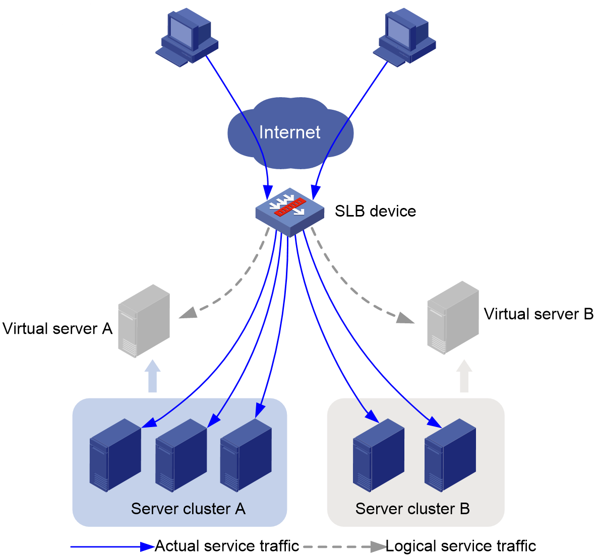
In the enterprise or large data center scenario, multiple servers are required to provide services. Server load balancing (SLB) appropriately distributes user traffic to multiple servers for processing to improve server resource utilization and user experience.
As shown in Figure 1, you can configure SLB by creating a virtual server with multiple real servers and advertising the virtual server IP address. When user traffic accesses the virtual server, SLB assigns the optimal server resources to user traffic based on the predefined scheduling algorithm and LB policy settings.
Figure 1 Server load balancing diagram
Basic concepts
· Virtual server—A logical entity used by the SLB device to provide services. It is uniquely identified by a protocol type, IP address, and port number. The SLB device performs load balancing for only the received packets matching a virtual server.
· Real server—A physical server that is responsible to respond and process user requests.
· Server farm—A cluster that contains multiple real servers to provide services.
SLB workflow
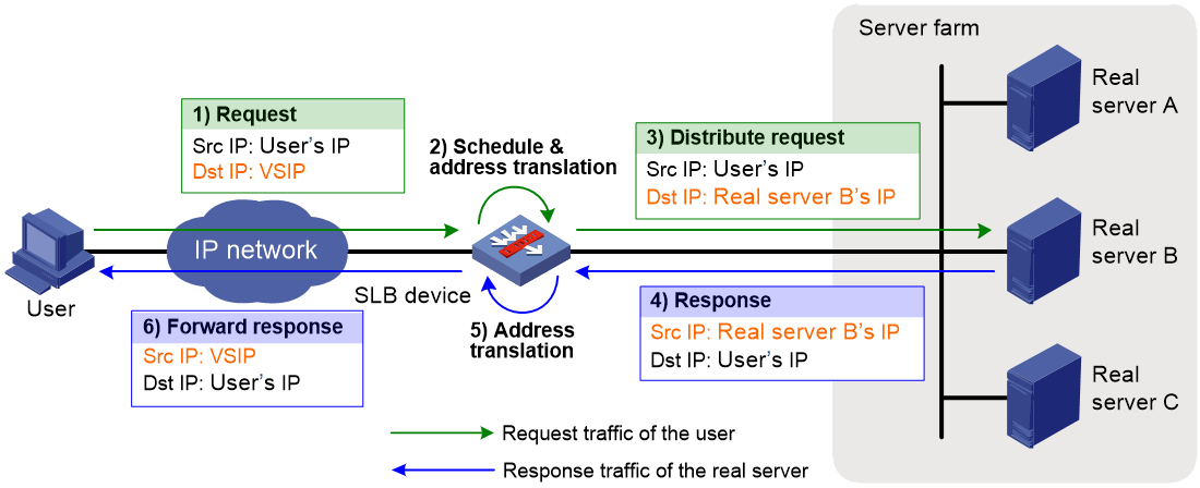
As shown in Figure 2, SLB works as follows:
1. The user sends a request to the SLB device. The user's IP address is the source IP address and the virtual server IP address (VSIP) is the destination IP address.
2. The SLB device calculates a real server based on the predefined health monitoring, sticky method, LB policy, and scheduling algorithm settings. Then, the SLB device sets the destination IP address of the request to the IP address of the calculated real server.
3. The SLB device forwards the request to the real server. The user's IP address is the source IP address and the IP address of the real server is the destination IP address.
4. The real server receives and processes the request, and then sends a response. The IP address of the real server is the source IP address and the user's IP address is the destination IP address.
5. The SLB device receives the response and sets the source IP address to the VSIP.
6. The SLB device forwards the request to the user with the VSIP as the source IP address and the user's IP address as the destination IP address.
Server load balancing types
Server load balancing is classified into Layer 4 server load balancing and Layer 7 server load balancing.
· Layer 4 server load balancing—Identifies network layer and transport layer information, and is implemented based on streams. It distributes packets in the same stream to the same server. Layer 4 server load balancing cannot distribute Layer 7 services based on contents.
· Layer 7 server load balancing—Identifies network layer, transport layer, and application layer information, and is implemented based on contents. It analyzes packet contents, distributes packets one by one based on the contents, and distributes connections to the specified server according to the predefined policies. Layer 7 server load balancing applies load balancing services to a large scope.
Scheduling algorithms
The device distributes user requests to real servers based on the specified scheduling rules and algorithms. The scheduling algorithm configured for a server farm calculates the real servers for processing user requests based on the factors such as device load and requested feature, implementing appropriate resource allocation and efficient task processing. Different scheduling algorithms are applicable to different scenarios. You must select the most appropriate scheduling algorithm based on the application requirements and system features to achieve performance optimization. SLB supports the following scheduling algorithms:
Random algorithm
This algorithm randomly assigns user requests to real servers. After a period of time, the number of connections on each real server is roughly the same.
Use the random algorithm in the scenarios where the real servers have similar performance and each flow has roughly the same service load, such as DNS and HTTP.
Weighted round robin algorithm
You can configure a weight for each real server that participates in scheduling. This algorithm assigns connections to real servers based on their weight values. A real server with a greater weight value is assigned more connections.
Use the weighted round robin algorithm in the scenarios where service hosts have different performances but the flows have similar service load.
Hash algorithms
Based on different packet information, SLB supports the source IP address hash algorithm, source IP address and port number hash algorithm, destination IP address hash algorithm, and HTTP hash algorithm.
· Source IP address hash algorithm—Applies to a scenario where user requests with the same source IP address need to be distributed to the same real server. Typically the application has specific requirements on the source IP address of requests. SLB supports the following source IP address hash algorithms:
¡ Common source IP address hash algorithm.
¡ Source IP address CARP hash algorithm—The Cache Array Routing Protocol (CARP) hash algorithm is an enhancement to the hash algorithm. Compared with the common source IP address hash algorithm, the source IP address CARP hash algorithm can better ensure persistence of traffic scheduling and the smallest load changes on all available real servers.
· Source IP address and port number hash algorithm—Applies to a scenario where user requests with the same source IP address and port number need to be distributed to the same real server. Typically the application has specific requirements on the source IP address and port number of requests. SLB supports the following source IP address and port number hash algorithms:
¡ Common source IP address and port number hash algorithm.
¡ Source IP address and port number CARP hash algorithm—The CARP hash algorithm is an enhancement to the hash algorithm. Compared with the common source IP address and port number hash algorithm, the source IP address and port number CARP hash algorithm can better ensure persistence of traffic scheduling and the smallest load changes on all available real servers.
· Destination IP address hash algorithm—Distributes user requests to different real servers according to the destination IP address of the user requests. This algorithm applies to a scenario where a client needs to communicate with a real server repeatedly. SLB supports the following destination IP address hash algorithms:
¡ Common destination IP address hash algorithm.
¡ Destination IP address CARP hash algorithm—The CARP hash algorithm is an enhancement to the hash algorithm. Compared with the common destination IP address hash algorithm, the destination IP address CARP hash algorithm can better ensure persistence of traffic scheduling and the smallest load changes on all available real servers.
· HTTP hash algorithm—This algorithm distributes user requests with the same HTTP payload to the same real server.
Based on algorithm implementation, SLB supports the common hash algorithm and CARP hash algorithm.
The CARP hash algorithm is an enhancement to the common hash algorithm. In the real server failure and server farm expansion scenarios, compared with the common hash algorithm, the CARP hash algorithm can better ensure the smallest load changes on all available real servers and persistence of traffic scheduling.
· If a real server fails to provide services, the requests previously assigned to this real server will be assigned to other available real servers in the server farm. The requests previously sent to the normal real servers will be assigned based on the specified scheduling algorithm as follows:
¡ Common IP address hash algorithm—Reassigns the requests to all real servers in the server farm based on the source IP address, source IP address and port number, destination IP address, or HTTP payload. All access traffic requires reassignment, which affects user experience.
¡ IP address CARP hash algorithm—Continues to assign the requests to the original real servers. This algorithm reassigns only the access traffic of the failed real server. Access traffic of normal real servers in the server farm is not affected.
· When you add new real servers to a server farm, the original requests will be assigned to real servers based on the specified scheduling algorithm as follows:
¡ Common IP address hash algorithm—Reassigns the requests to all real servers (including the newly added and existing real servers) in the server farm based on the source IP address, source IP address and port number, destination IP address, or HTTP payload. All access traffic requires reassignment, which affects user experience.
¡ IP address CARP hash algorithm—Assigns a small portion of the requests to the newly added real servers, and assigns most requests to the existing real servers. This algorithm can better ensure access experience of users.
Dynamic feedback algorithm
This algorithm calculates load weight values by using the memory, CPU, and disk usage of the real servers. The less the load, the greater the weight value. A real server with a greater weight value is assigned more connections.
This algorithm can take effect only if you specify an SNMP-DCA NQA template. If the SNMP-DCA NQA probe template is not specified, the non-weighted round robin algorithm is used for scheduling. The SNMP-DCA NQA probe template sends query packets to the real server to obtain resource usage information, such as CPU, memory, and disk. The dynamic feedback algorithm calculates the load capacity weight for a real server based on the resource usage obtained through the NQA probe template. For more information about NQA templates, see NQA configuration in Network Management and Monitoring Configuration Guide.
Use the dynamic feedback algorithm in the scenarios where the real servers have different performances and the service load and processing time of each flow lack a specific pattern.
Weighted least connection algorithm
You can configure a weight for each real server that participates in scheduling. The weight reflects the processing capability or performance of the real servers. This algorithm always assigns user requests to the real server with the fewest number of weighted active connections (the total number of active connections of the real server divided by weight).
Use the weighted least connection algorithm in the scenarios where the real servers have similar performance but each flow has a different service load and processing time, such as FTP.
Least time algorithm
The least time algorithm calculates load weight values by using the response time of the real servers. The shorter the response time, the greater the weight value. A real server with a greater weight value is assigned more connections.
Use the least time algorithm in the scenarios where the real servers have similar performance, but each flow has a large service load and long processing time.
Bandwidth algorithm
This algorithm distributes user requests to real servers according to the weights and remaining bandwidth of real servers.
Maximum bandwidth algorithm
This algorithm distributes user requests always to an idle real server that has the largest remaining bandwidth.
Health monitoring
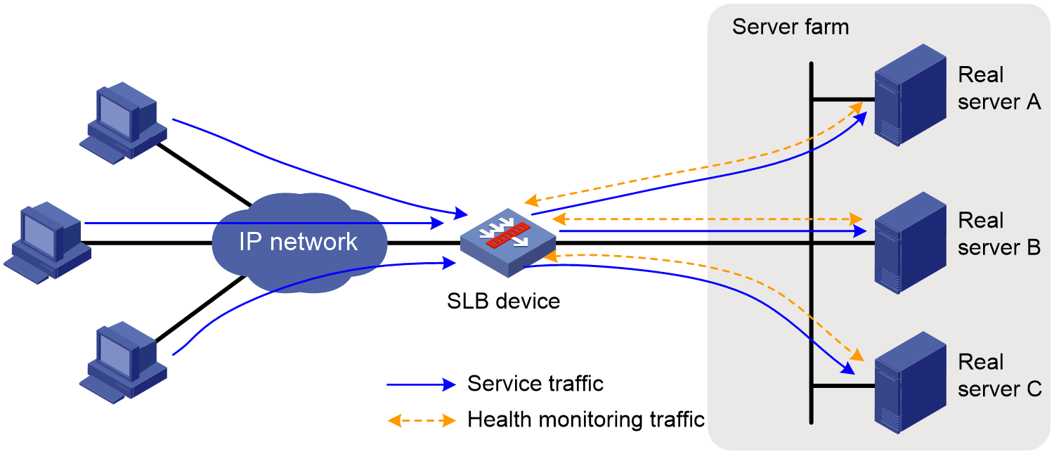
Health monitoring periodically detects the state of real servers to make sure they can provide services correctly. The SLB device actively sends probe packets to the real servers to detect their states in real time. This can avoid assigning traffic to faulty real servers, which results in service interruption.
As shown in Figure 3, if the SLB device detects that all real servers are in normal state, it assigns client traffic to each real server based on the scheduling algorithm. (In this example, the same weight value is configured for all real servers, and the weighted round robin algorithm is used.)
Figure 3 Health monitoring diagram (all real servers are in normal state)
As shown in Figure 4, upon detecting a real server failure, the SLB device immediately stops assigning traffic to the real server, and schedules traffic to other real servers in normal state.
Figure 4 Health monitoring diagram (a real server becomes faulty)
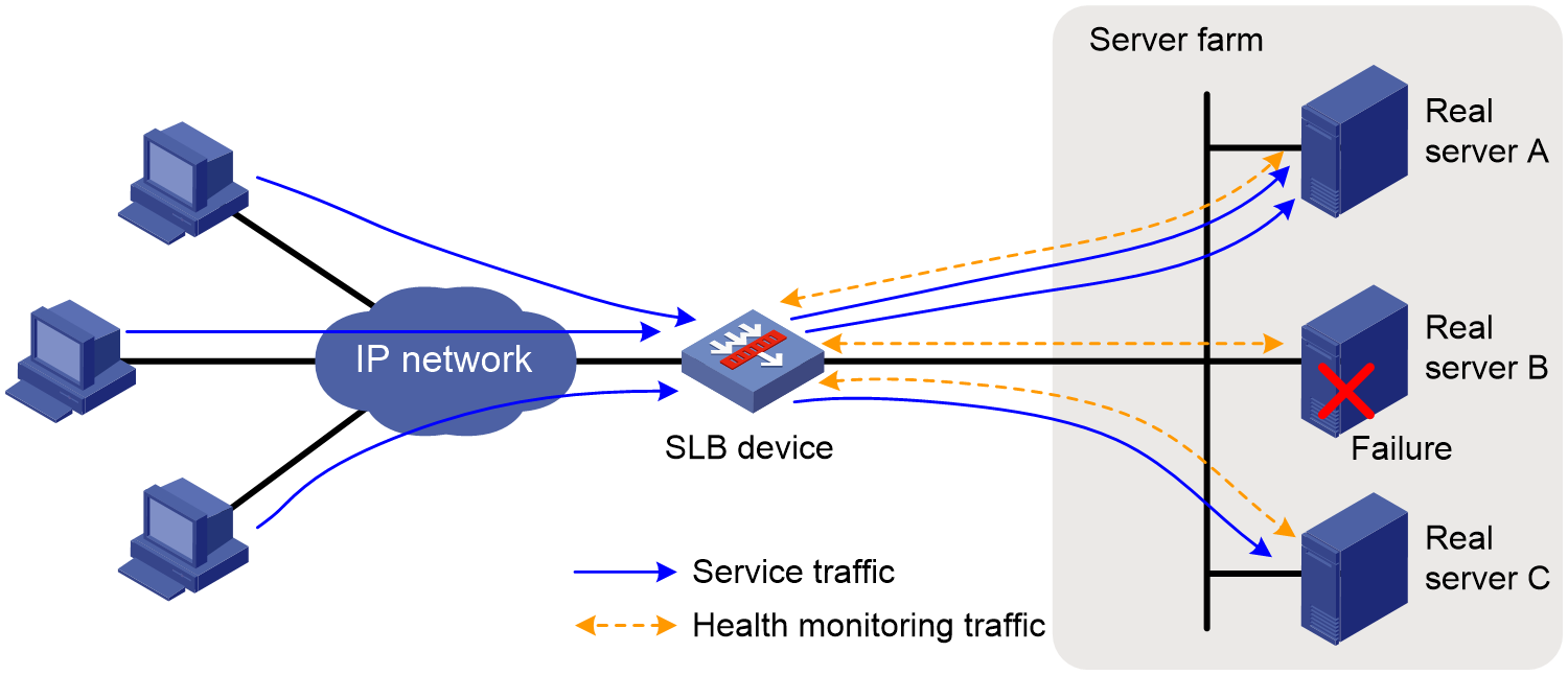
After a period of time, if the faulty server returns to normal status, the device will update the server's health monitoring state, allowing it to participate in scheduling again.
You can specify an LB template or NQA template for health monitoring. For information about LB templates, see "Configuring an LB probe template." For information about NQA templates, see NQA configuration in Network Management and Monitoring Configuration Guide.
LB policies
LB policies determine how to assign client request traffic to the actual service farms. You can select the appropriate LB policy and LB algorithm to achieve optimal load balancing results. The LB policy assigns user traffic that meets specific rules to the specified server farm. The scheduling algorithm selects the optimal real server within the server farm.
An LB policy associates a class with an action to guide packet forwarding. In an LB policy, you can configure an action for packets matching the specified class to implement load balancing in a more flexible way.
LB classes
You can specify multiple LB classes for an LB policy. Packets match the LB classes in the order the LB classes are configured.
· For an LB class of the match-any type, the specified action is taken on the packets when they match any rule. If no rule is matched, no action is taken.
· For an LB class of the match-all type, the specified action is taken only when the packets match all rules.
LB actions
LB actions include the following modes:
· Forwarding mode—Determines whether and how to forward packets. If no forwarding action is specified, packets are dropped.
· Modification mode—Modifies packets. To prevent the device from dropping the modified packets, the modification action must be used together with a forwarding action.
· Response mode—Responds to client HTTP requests by using a file.
To drop matching packets, create an LB action without specifying any of the previous action modes.
Sticky groups
A sticky group uses a sticky method to distribute similar sessions to the same real server according to sticky entries. It ensures continuous user access and reduces repeated calculations of scheduling algorithms, enhancing forwarding efficiency.
A typical application scenario is as follows: For specific services, the server saves user information after the first request to reduce the response time for consecutive requests. In this case, as a best practice, configure a sticky group to always assign requests from the same user to the same real server.
A sticky group processes packets as follows:
1. The device assigns the first packet of a session to a real server according to the scheduling algorithm. In addition, the device generates a sticky entry according to the sticky method.
2. Upon receiving subsequent packets of the session, the device assigns them the same real server according the sticky entry.
SLB deployment modes
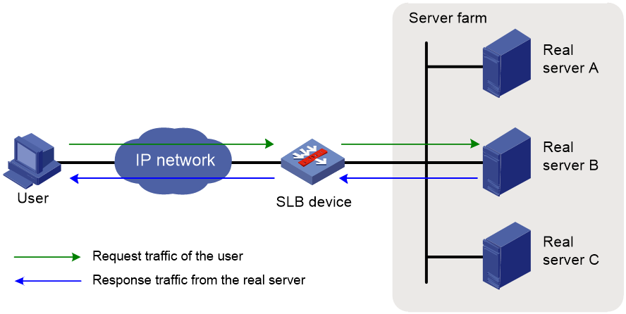
Gateway mode
As shown in Figure 5, in the gateway mode, the SLB device is directly connected to the real servers and processes both of the requests and responses. When the SLB device receives a user request, it uses the predefined health monitoring, sticky method, LB policy, and scheduling algorithm settings to calculate a real server for distributing the request. Then, the SLB device sets the destination IP address of the request to the IP address of the calculated real server. When the SLB device receives a response from the real server, it sets the source IP address to the VSIP.
Gateway-mode SLB requires you to configure the default gateway or a static route for the real server. The real server can then send packets destined to the user through the SLB device.
The gateway mode typically applies to small networks, because the deployment of the SLB device changes the network topology.
Figure 5 Gateway-mode SLB deployment
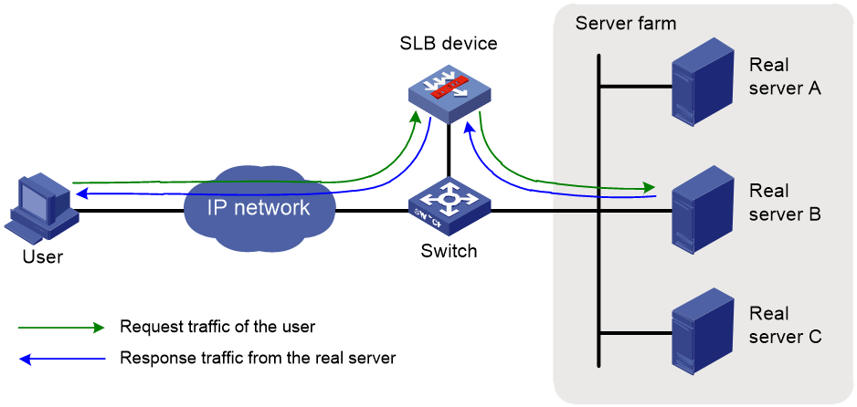
Indirect mode
As shown in Figure 6, in the indirect mode, the SLB device is attached to the core switch and processes both of the requests and responses.
When the SLB device receives a user request, it uses the predefined health monitoring, sticky method, LB policy, and scheduling algorithm settings to calculate a real server for distributing the request. Then, the SLB device sets the destination IP address of the request to the IP address of the calculated real server. When the SLB device receives a response from the real server, it sets the source IP address to the VSIP.
Indirect-mode SLB requires you to configure the default gateway or a static route for the real server. The real server can then send packets destined to the user through the core switch to which the SLB device is attached.
The indirect mode is more flexible, because the SLB device deployment does not change the network topology.
Figure 6 Indirect-mode SLB deployment
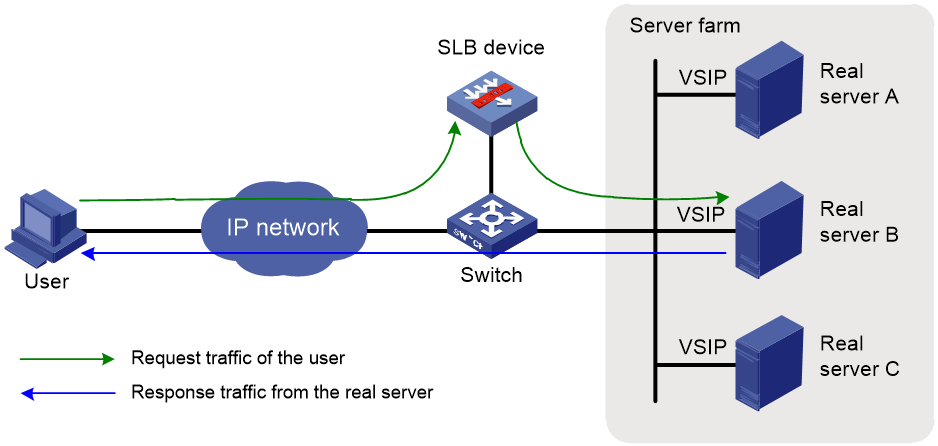
Triangle mode
As shown in Figure 7, in the triangle mode, the SLB device is attached to the core switch and processes only user requests. The SLB device does not process the responses from the real servers. When the SLB device receives a request from the user, it uses the predefined health monitoring, sticky method, LB policy, and scheduling algorithm settings to calculate a real server for distributing the request. Then, the SLB device distributes the request to the calculated real server, with the VSIP as the destination IP address but the MAC address of the real server as the destination MAC address. When the real server receives the request, it processes the request and sends a response directly to the user, with the VSIP as the source IP address and the user's IP address as the destination IP address.
Triangle-mode server load balancing requires configuring the default gateway or a static route for the real server to send packets destined to the user through the gateway. In addition, you must configure the VSIP for the loopback interface on each real server.
The triangle mode is flexible, because the SLB device deployment does not change the network topology. It typically applies to the scenarios with heavy traffic, such as video services, because the response traffic does not go through the SLB device.
Figure 7 Triangle-mode SLB deployment
Server load balancing tasks at a glance
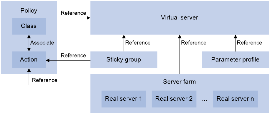
Relationship between configuration items
Figure 8 shows the relationship between the following configuration items:
· Server farm—A collection of real servers that contain similar content. A sever farm can be referenced by a virtual server or an LB action.
· Real server—An entity on the LB device to process user services.
· Virtual server—A virtual service provided by the LB device to determine whether to perform load balancing for packets received on the LB device. Only the packets that match a virtual server are load balanced.
· LB class—Classifies packets to implement load balancing based on packet type.
· LB action—Drops, forwards, or modifies packets.
· LB policy—Associates an LB class with an LB action. An LB policy can be referenced by a virtual server.
· Sticky group—Uses a sticky method to distribute similar sessions to the same real server. A sticky group can be referenced by a virtual server or an LB action.
· Parameter profile—Defines advanced parameters to process packets. A parameter profile can be referenced by a virtual server.
Figure 8 Relationship between the main configuration items
Tasks at a glance
To configure server load balancing, perform the following tasks:
3. Configuring a virtual server
4. (Optional.) Configuring an LB policy
5. (Optional.) Configuring a sticky group
6. (Optional.) Configuring templates and policies
¡ Configuring a parameter profile
¡ Configuring a protection policy
¡ Configuring an LB probe template
¡ Configuring an LB connection limit policy
7. (Optional.) Configuring a SNAT global policy
8. (Optional.) Configuring the ALG feature
9. (Optional.) Reloading a response file
10. (Optional.) Specifying an action to take on the Timestamps option in TCP packet headers
11. (Optional.) Configuring recording of health monitoring failures
12. (Optional.) Configuring the cache limit for SSL performance optimization
13. (Optional.) Performing a load balancing test
14. (Optional.) Configuring SNMP notifications and logging for load balancing
¡ Enabling load balancing logging
Configuring a server farm
You can add real servers that contain similar content to a server farm to facilitate management.
Server farm tasks at a glance
The server farm configuration tasks for Layer 4 and Layer 7 server load balancing are the same.
To configure a server farm, perform the following tasks:
2. (Optional.) Adding and configuring a server farm member
3. Configuring scheduling algorithms for a server farm
4. Configuring NAT
Choose the following tasks as needed:
¡ Configuring indirect-mode NAT
5. Setting the availability criteria
6. (Optional.) Enabling the slow online feature
7. (Optional.) Configuring health monitoring
8. (Optional.) Configuring custom monitoring
9. (Optional.) Configuring intelligent monitoring
10. (Optional.) Configuring the action to take when a server farm is busy
11. (Optional.) Specifying a fault processing method
Creating a server farm
1. Enter system view.
system-view
2. Create a server farm and enter server farm view.
server-farm server-farm-name
3. (Optional.) Configure a description for the server farm.
description text
By default, no description is configured for the server farm.
Adding and configuring a server farm member
About this task
Perform this task to create a server farm member or add an existing real server as a server farm member in server farm view. You can also specify a server farm for a real server in real server view to achieve the same purpose (see "Creating a real server and specifying a server farm").
After adding a server farm member, you can configure the following parameters and features for the real server in the server farm:
· Weight.
· Priority.
· Connection limits.
· Health monitoring.
· Slow shutdown.
· Slow offline.
The member-based scheduling algorithm selects the best real server based on these configurations.
The slow shutdown and slow offline features do not terminate existing connections and wait them to age out. The slow shutdown feature does not create new connections, and the slow offline feature creates connections for traffic that matches an exiting sticky entry and continues to perform health monitoring on the server farm member.
Restrictions and guidelines
Use the slow shutdown feature before you maintain or upgrade a server farm member to avoid bad user experience caused by sudden disconnections. Use the slow offline feature if you want to remove a server farm member and then add it again at a later time. With the slow offline feature, you can also monitor the state of the server farm member in real time.
The slow shutdown and slow offline features are mutually exclusive. A subsequently configured feature overwrites the previously configured feature.
For the slow shutdown or slow offline feature to take effect, you must execute the shutdown command after enabling that feature.
If you execute only the shutdown command, existing connections are terminated immediately.
Adding a server farm member
1. Enter system view.
system-view
2. Enter server farm view.
server-farm server-farm-name
3. Create and add a server farm member and enter server farm member view.
real-server real-server-name port port-number
If the real server already exists, the command adds the existing real server as a server farm member.
If you configure a domain name on a real server and receive the domain name resolution result, the server farm will automatically reference the temporary server farm members corresponding to the domain name resolution result after referencing the real server. The name of a temporary member is in the auto_IP address form, for example, auto_1.1.1.1.
4. (Optional.) Configure a description for the server farm member.
description text
By default, no description is configured for the server farm member.
Setting the weight and priority of the server farm member
1. Enter system view.
system-view
2. Enter server farm view.
server-farm server-farm-name
3. Enter server farm member view.
real-server real-server-name port port-number
4. Set the weight of the server farm member.
weight weight-value
The default setting is 100.
5. Set the priority of the server farm member.
priority priority
The default setting is 4.
Setting the connection limits of the server farm member
1. Enter system view.
system-view
2. Enter server farm view.
server-farm server-farm-name
3. Enter server farm member view.
real-server real-server-name port port-number
4. Set the connection rate of the server farm member.
rate-limit connection connection-number
The default setting is 0 (the connection rate is not limited).
5. Set the maximum number of connections allowed for the server farm member.
connection-limit max max-number
The default setting is 0 (the maximum number of connections is not limited).
6. Set the maximum number of HTTP requests per second for the server farm member.
rate-limit http-request request-number
The default setting is 0 (the maximum number of HTTP requests per second is not limited).
Configuring health monitoring for the server farm member
1. Enter system view.
system-view
2. Enter server farm view.
server-farm server-farm-name
3. Enter server farm member view.
real-server real-server-name port port-number
4. Specify a health monitoring method for the server farm member.
probe template-name [ nqa-template-port ]
By default, no health monitoring method is specified for the server farm member.
You can specify an NQA template for health monitoring. For information about NQA templates, see NQA configuration in Network Management and Monitoring Configuration Guide.
5. Specify the health monitoring success criteria for the server farm member.
success-criteria { all | at-least min-number }
By default, health monitoring succeeds only when all the specified health monitoring methods succeed.
6. (Optional.) Enable health monitoring logging for the server farm member.
probe log enable
By default, health monitoring logging is enabled for a server farm member.
Configuring custom monitoring
1. Enter system view.
system-view
2. Enter server farm view.
server-farm server-farm-name
3. Enter server farm member view.
real-server real-server-name port port-number
4. Specify a custom-monitoring LB probe template for the server farm member.
probe-template external-monitor template-name
By default, no custom-monitoring LB probe template is specified for a server farm member.
Enabling the slow shutdown feature for the server farm member
1. Enter system view.
system-view
2. Enter server farm view.
server-farm server-farm-name
3. Enter server farm member view.
real-server real-server-name port port-number
4. Enable the slow shutdown feature for the server farm member.
slow-shutdown enable
By default, the slow shutdown feature is disabled.
5. Shut down the server farm member.
shutdown
By default, the server farm member is activated.
Enabling the slow offline feature for the server farm member
1. Enter system view.
system-view
2. Enter server farm view.
server-farm server-farm-name
3. Enter server farm member view.
real-server real-server-name port port-number
4. Enable the slow offline feature for the server farm member.
slow-offline enable
By default, the slow offline feature is disabled.
5. Shut down the server farm member.
shutdown
By default, the server farm member is activated.
Associating a variable with the server farm member
1. Enter system view.
system-view
2. Enter server farm view.
server-farm server-farm-name
3. Enter server farm member view.
real-server real-server-name port port-number
4. Associate a variable with the server farm member.
variable variable-name value value
By default, no variable is associated with a server farm member.
By using a TCP payload rewrite LB action, you can replace the specified content in a TCP payload with the variable associated with the server farm member.
Configure the action on packets when all server farm members are unavailable
1. Enter system view.
system-view
2. Enter server farm view.
server-farm server-farm-name
3. Enable the device to forward packets to the last selected server farm member when all server farm members are unavailable.
all-service-down action forward
By default, the device drops packets when all server farm members are unavailable.
This command takes effect only when the server farm is referenced by a TCP virtual server operating in Layer 7.
Configuring scheduling algorithms for a server farm
The LB device calculates the real servers to process user requests based on the specified scheduling algorithm. For more information about scheduling algorithms, see "Scheduling algorithms."
The weighted least connection algorithm and lease time algorithm can be classified into the following types based on the calculation scope:
· Scheduling algorithms based on real servers—The algorithms use the performance parameters of the real servers and the weight values configured in real server view.
· Scheduling algorithms based on server farm members—The algorithms use the performance parameters of the server farm members and the weight values configured in server farm member view.
Procedure
1. Enter system view.
system-view
2. Enter server farm view.
server-farm server-farm-name
3. Specify a scheduling algorithm for the server farm.
¡ Specify a real server-based scheduling algorithm.
predictor { dync-round-robin | least-connection | least-time | { bandwidth | max-bandwidth } [ inbound | outbound ] }
¡ Specify a server farm member-based scheduling algorithm.
predictor hash [ carp ] address { destination | source | source-ip-port } [ mask mask-length ] [ prefix prefix-length ]
predictor hash [ carp ] http [ offset offset ] [ start start-string ] [ [ end end-string ] | [ length length ] ]
predictor { least-connection member [ slow-online ] | random | round-robin }
By default, the scheduling algorithm for the server farm is weighted round robin.
4. Specify the number of real servers to participate in scheduling.
selected-server min min-number max max-number
By default, the real servers with the highest priority participate in scheduling.
Configuring indirect-mode NAT
Restrictions and guidelines
Indirect-mode NAT configuration requires disabling NAT for the server farm.
Procedure
1. Enter system view.
system-view
2. Enter server farm view.
server-farm server-farm-name
3. Disable NAT for the server farm.
transparent enable
By default, NAT is enabled for a server farm.
If the server farm is referenced by a virtual server of the HTTP type, the NAT feature takes effect even if it is disabled.
Configuring NAT-mode NAT
About this task
The NAT-mode NAT configuration varies by NAT mode.
· For DNAT mode, you only need to enable NAT for the server farm.
· For SNAT mode and DNAT + SNAT mode, you must configure one of the following translation modes in server farm view:
¡ Automatic mapping—Translates the source IP address into the IP address of the interface connecting to the real servers.
¡ TCP option—Translates the source IP address into the IP address carried in the TCP option field of packets. For this mode, you must configure the TCP option for address translation (see "Configuring the TCP option for SNAT").
¡ SNAT address pool—Translates the source IP address into an IP address in the specified SNAT address pool.
When multiple service modules are installed on the device, address conflicts might occur among the service modules. To solve this problem, you can split a SNAT address pool by using the following methods:
· Address-based splitting—Evenly divides IP addresses in the address pool among failover groups. Each failover group uses a unique subset of the IP addresses in the address pool.
· Port-based splitting—Evenly divides port numbers in the address pool among failover groups. Each failover group uses the full set of the IP addresses in the address pool, with a different set of port numbers.
· Failover group-based splitting—Uses an IP address range in an address pool only for a specific failover group. When you configure an IP address range for an address pool, you can specify the failover group to use that IP address range.
For more information about failover groups, see failover group configuration in High Availability Configuration Guide.
1. The MAC address of the corresponding interface is used.
Restrictions and guidelines
An SNAT address pool can have multiple address ranges. Each address range can have a maximum of 256 IPv4 addresses or 10000 IPv6 addresses. No overlapping IPv4 or IPv6 addresses are allowed in the same SNAT address pool or different SNAT address pools.
For the TCP option mode, you must insert the IP address used to replace the source IP address into the specified TCP option.
If the addresses in an SNAT address pool are in the same network segment as the IP address of the interface connect the device to the server, you must specify an interface for sending gratuitous ARP or ND packets.
Configuring DNAT
1. Enter system view.
system-view
2. Enter server farm view.
server-farm server-farm-name
3. Enable NAT for the server farm.
undo transparent enable
By default, NAT is enabled for a server farm.
If the server farm is referenced by a virtual server of the HTTP type, the NAT feature takes effect even if it is disabled.
Configuring SNAT and DNAT+SNAT
1. Enter system view.
system-view
2. (Optional.) Configure a SNAT address pool.
a. Create a SNAT address pool and enter SNAT address pool view.
loadbalance snat-pool pool-name
b. (Optional.) Configure a description for the SNAT address pool.
description text
By default, no description is configured for a SNAT address pool.
c. Specify an address range for the SNAT address pool.
IPv4:
ip range start start-ipv4-address end end-ipv4-address
IPv6:
ipv6 range start start-ipv6-address end end-ipv6-address
By default, no address range is specified for a SNAT address pool.
This step is required for the SNAT address pool translation mode.
d. (Optional.) Specify a VRRP group for the SNAT address pool.
vrrp [ ipv6 ] vrid virtual-router-id interface interface-type interface-number
By default, an SNAT address pool is not bound to any VRRP group.
An SNAT address pool can be bound to a maximum of one IPv4 VRRP group and a maximum of one IPv6 VRRP group.
e. (Optional.) Specify a cluster traffic group for the SNAT address pool.
traffic-group traffic-group-id
By default, an SNAT address pool is not bound to any cluster traffic group.
To bind an SNAT address pool to a cluster traffic group, make sure the current device has been added to traffic group. For more information about traffic groups, see RBM configuration in High Availability Configuration Guide.
3. (Optional.) Specify an interface for sending gratuitous ARP packets and ND packets.
arp-nd interface interface-type interface-number
By default, no interface is specified for sending gratuitous ARP packets and ND packets.
4. Return to system view.
quit
5. Enter server farm view.
server-farm server-farm-name
6. Enable NAT for the server farm.
undo transparent enable
By default, NAT is enabled for a server farm.
If a server farm is referenced by a virtual server of the HTTP type, the NAT feature takes effect even when it is disabled.
7. Configure a translation mode.
¡ Configure the automatic mapping mode.
snat-mode auto-map
¡ Configure the TCP option mode.
snat-mode tcp-option
¡ Configure the SNAT address pool mode.
snat-pool pool-name
By default, no translation mode is configured.
Setting the availability criteria
About this task
Perform this task to set the criteria (lower percentage and higher percentage) to determine whether a server farm is available. This helps implement traffic switchover between the master and backup server farms.
· When the number of available real servers to the total number of real servers in the master server farm is smaller than the lower percentage, traffic is switched to the backup server farm.
· When the number of available real servers to the total number of real servers in the master server farm is greater than the upper percentage, traffic is switched back to the master server farm.
Procedure
1. Enter system view.
system-view
2. Enter server farm view.
server-farm server-farm-name
3. Set the criteria to determine whether the server farm is available.
activate lower lower-percentage upper upper-percentage
By default, when a minimum of one real server is available, the server farm is available.
Enabling the slow online feature
About this task
The real servers newly added to a server farm might not be able to immediately process large numbers of services assigned by the LB device. To resolve this issue, enable the slow online feature for the server farm. The feature uses the standby timer and ramp-up timer. When the real servers are brought online, the LB device does not assign any services to the real servers until the standby timer expires.
When the standby timer expires, the ramp-up timer starts. During the ramp-up time, the LB device increases the service amount according to the processing capability of the real servers, until the ramp-up timer expires.
Procedure
1. Enter system view.
system-view
2. Enter server farm view.
server-farm server-farm-name
3. Enable the slow online feature for the server farm.
slow-online [ standby-time standby-time ramp-up-time ramp-up-time ]
By default, the slow online feature is disabled for the server farm.
Configuring health monitoring
About this task
Perform this task to enable health monitoring to detect the availability of real servers.
Restrictions and guidelines
The health monitoring configuration in server farm view takes effect on all members in the server farm. The health monitoring configuration in server farm member view takes effect only on the member. The health monitoring configuration in real server view takes effect only on the real server. The health monitoring configuration in server farm member view has the same priority with that in real server view, and the configuration in both views takes precedence over the configuration in server farm view. As a best practice, configure health monitoring in server farm view.
You can specify an NQA template for health monitoring. For information about NQA templates, see NQA configuration in Network Management and Monitoring Configuration Guide.
Procedure
1. Enter system view.
system-view
2. Enter server farm view.
server-farm server-farm-name
3. Specify a health monitoring method for the server farm.
probe template-name [ nqa-template-port ]
By default, no health monitoring method is specified for the server farm.
4. Specify the health monitoring success criteria for the server farm.
success-criteria { all | at-least min-number }
By default, health monitoring succeeds only when all the specified health monitoring methods succeed.
Configuring intelligent monitoring
About this task
Intelligent monitoring identifies the health of server farm members by counting the number of URL errors in HTTP responses or the number of RST packets or zero-window packets sent by each server farm member. Upon packet threshold violation, a protection action is taken. This feature is implemented by referencing a TCP-RST, TCP zero-window, or HTTP passive LB probe template in server farm view.
You can use the following methods to recover a server farm member placed in Auto shutdown state by this feature:
· Set the automatic recovery time in server farm view for the server farm member to automatically recover.
· Manually recover the server farm member.
If health monitoring manual recovery is enabled, when a server farm member passes a health check, it will not automatically return to normal state. You need to manually restore it to normal state in server farm member view.
Restrictions and guidelines
A real server that is shut down or placed in busy state due to packet threshold violation will be restored to the normal state immediately when the referenced probe template is deleted.
If the upper limit of URL error times is reached, the real server is automatically shut down. When the HTTP passive probe template is deleted, the real server is restored to normal state immediately.
Prerequisites
Before configuring this feature, configure an LB probe template (see "Configuring an LB probe template").
Specifying an LB probe template for a server farm
1. Enter system view.
system-view
2. Enter server farm view.
server-farm server-farm-name
3. Specify an LB probe template for the server farm.
probe-template { http-passive | tcp-rst | tcp-zero-window | database { antdb | mysql | oracle } template-name
By default, no LB probe template is specified for a server farm.
4. (Optional.) Set the automatic recovery time.
auto-shutdown recovery-time recovery-time
By default, the automatic recovery time is 0 seconds, which means that a server farm member placed in Auto shutdown state does not automatically recover.
5. (Optional.) Enable health monitoring manual recovery.
manual-recover enable
By default, health monitoring manual recovery is disabled.
Manually recovering a real server
1. Enter system view.
system-view
2. Enter real server view.
real-server real-server-name
3. Manually recover the real server.
recover-to-active
Manually recovering a server farm member
1. Enter system view.
system-view
2. Enter server farm view.
server-farm server-farm-name
3. Enter server farm member view.
real-server real-server-name port port-number
4. Manually recover the server farm member.
recover-to-active
Configuring custom monitoring
About this task
This feature allows you to use a custom script file to monitor the state of server farm members.
Restrictions and guidelines
You can configure this feature for all server farm members in server farm view or for a single server farm member in server farm member view. If you configure this feature in both server farm view and server farm member view, the configuration in server farm member view takes effect.
Prerequisites
Before configuring this feature, configure the LB probe template (see "Configuring an LB probe template").
Procedure
1. Enter system view.
system-view
2. Enter server farm view.
server-farm server-farm-name
3. Specify a custom-monitoring LB probe template for the server farm.
probe-template external-monitor template-name
By default, no custom-monitoring LB probe template is specified for a server farm.
Configuring the action to take when a server farm is busy
About this task
A server farm is considered busy when all its real servers are busy. You can configure one of the following actions:
· drop—Stops assigning client requests to a server farm. If the LB policy for the server farm contains the action of matching the next rule, the device compares client requests with the next rule. Otherwise, the device drops the client requests.
· enqueue—Stops assigning client requests to a server farm and assigns new client requests to a wait queue. New client requests will be dropped when the queue length exceeds the configured length. Client requests already in the queue will be aged out when the configured timeout time expires.
· force—Forcibly assigns client requests to all real servers in the server farm.
The device determines whether a real server is busy based on the following factors:
· Maximum number of connections.
· Maximum number of connections per second.
· Maximum number of HTTP requests per second.
· Maximum bandwidth.
· SNMP-DCA probe result.
Procedure
1. Enter system view.
system-view
2. Enter server farm view.
server-farm server-farm-name
3. Configure the action to take when the server farm is busy.
busy-action { drop | enqueue length length timeout timeout-value | force }
The default action is drop.
Specifying a fault processing method
About this task
Perform this task to specify one of the following fault processing methods for a server farm when a real server fails:
· Keep—Does not actively terminate the connection with the failed real server. Keeping or terminating the connection depends on the timeout mechanism of the protocol.
· Reschedule—Redirects the connection to another available real server in the server farm.
· Reset—Terminates the connection with the failed real server by sending RST packets (for TCP packets) or ICMP unreachable packets (for other types of packets).
Procedure
1. Enter system view.
system-view
2. Enter server farm view.
server-farm server-farm-name
3. Specify a fault processing method for the server farm.
fail-action { keep | reschedule | reset }
By default, the fault processing method is keep. All available connections are kept.
Configuring a real server
A real server is an entity on the LB device to process user services. A real server can belong to multiple server farms. A server farm can have multiple real servers.
Real server tasks at a glance
The real server configuration tasks for Layer 4 and Layer 7 server load balancing are the same.
To configure a real server, perform the following tasks:
1. Creating a real server and specifying a server farm
2. Specifying an IP address, domain name, and port number
3. Setting a weight and priority
4. (Optional.) Configuring the bandwidth and connection parameters
5. (Optional.) Configuring health monitoring
6. (Optional.) Configuring custom monitoring
7. (Optional.) Enabling the slow shutdown feature
8. (Optional.) Enabling the slow offline feature
Creating a real server and specifying a server farm
1. Enter system view.
system-view
2. Create a real server and enter real server view.
real-server real-server-name
3. (Optional.) Configure a description for the real server.
description text
By default, no description is configured for the real server.
4. Specify a server farm for the real server.
server-farm server-farm-name
By default, the real server does not belong to any server farms.
Specifying an IP address, domain name, and port number
1. Enter system view.
system-view
2. Enter real server view.
real-server real-server-name
3. Specify an IP address or domain name for the real server. Choose one option as needed:
¡ Specify an IP address for the real server.
IPv4:
ip address ipv4-address
IPv6:
ipv6 address ipv6-address
By default, no IP address is specified for the real server.
¡ Specify a domain name for the real server.
domain-name domain-name
By default, no domain name is specified for the real server.
4. Specify the port number for the real server.
port port-number
By default, the port number of the real server is 0. Packets use their respective port numbers.
Setting a weight and priority
About this task
Perform this task to set a weight for scheduling algorithms of a real server, and the scheduling priority in the server farm for the server.
Procedure
1. Enter system view.
system-view
2. Enter real server view.
real-server real-server-name
3. Set a weight for the real server.
weight weight-value
By default, the weight of the real server is 100.
4. Set a priority for the real server.
priority priority
By default, the priority of the real server is 4.
Configuring the bandwidth and connection parameters
About this task
This task allows you to configure the following parameters:
· Maximum bandwidth.
· Maximum number of connections.
· Maximum number of connections per second.
· Maximum number of HTTP requests per second.
If any of the preceding thresholds is exceeded, the real server is placed in busy state.
Procedure
1. Enter system view.
system-view
2. Enter real server view.
real-server real-server-name
3. Set the maximum bandwidth for the real server.
rate-limit bandwidth [ inbound | outbound ] bandwidth-value kbps
By default, the maximum bandwidth, inbound bandwidth, and outbound bandwidth are 0 for the real server. The bandwidths are not limited.
4. Set the maximum number of connections for the real server.
connection-limit max max-number
By default, the maximum number of connections is 0 for the real server. The number is not limited.
5. Set the maximum number of connections per second for the real server.
rate-limit connection connection-number
By default, the maximum number of connections per second is 0 for the real server. The number is not limited.
6. Set the maximum number of HTTP requests per second for the real server.
rate-limit http-request request-number
By default, the maximum number of HTTP requests per second is 0 for the real server. The number is not limited.
Configuring health monitoring
About this task
Perform this task to enable health monitoring to detect the availability of a real server.
Restrictions and guidelines
The health monitoring configuration in server farm view takes effect on all members in the server farm. The health monitoring configuration in server farm member view takes effect only on the member. The health monitoring configuration in real server view takes effect only on the real server. The health monitoring configuration in server farm member view has the same priority with that in real server view, and the configuration in both views takes precedence over the configuration in server farm view. As a best practice, configure health monitoring in server farm view.
The health monitoring result of a real server affects the usage of server farm member, but the health monitoring result of a server farm member do not affect the usage of real server.
Procedure
1. Enter system view.
system-view
2. Enter real server view.
real-server real-server-name
3. Specify a health monitoring method for the real server.
probe template-name [ nqa-template-port ]
By default, no health monitoring method is specified for the real server.
4. Specify the health monitoring success criteria for the real server.
success-criteria { all | at-least min-number }
By default, the health monitoring succeeds only when all the specified health monitoring methods succeed.
5. Return to system view.
quit
6. (Optional.) Enable health monitoring logging for the real server.
probe log enable
By default, health monitoring logging is enabled for a real server.
Configuring custom monitoring
About this task
This feature allows you to use a custom script file to monitor the state of real servers.
Prerequisites
Before configuring this feature, configure the LB probe template (see "Configuring an LB probe template").
Procedure
1. Enter system view.
system-view
2. Enter real server view.
real-server real-server-name
3. Specify a custom-monitoring LB probe template for the real server.
probe-template external-monitor template-name
By default, no custom-monitoring LB probe template is specified for a real server.
Enabling the slow shutdown feature
About this task
The shutdown command immediately terminates existing connections of a real server. The slow shutdown feature ages out the connections, and does not establish new connections.
Restrictions and guidelines
Use this feature before you maintain or upgrade a server farm member to avoid bad user experience caused by sudden disconnections.
To enable the slow shutdown feature for a real server, you must execute the slow-shutdown enable command and then the shutdown command. If you execute the shutdown command and then the slow-shutdown enable command, the slow shutdown feature does not take effect and the real server is shut down.
This feature and the slow offline feature are mutually exclusive. A subsequently configured feature overwrites the previously configured feature.
Procedure
1. Enter system view.
system-view
2. Enter real server view.
real-server real-server-name
3. Enable the slow shutdown feature for the real server.
slow-shutdown enable
By default, the slow shutdown feature is disabled.
4. Shut down the real server.
shutdown
By default, the real server is activated.
Enabling the slow offline feature
About this task
The slow offline feature processes traffic of existing connections and creates connections for traffic that matches an existing sticky entry. This feature also allows the device to continue health monitoring on the real server.
Restrictions and guidelines
Use this feature if you want to remove a server farm member and then add it again at a later time..
To enable the slow offline feature for a real server, you must execute the slow-offline enable command and then the offline command. If you execute the offline command and then the slow-offline enable command, the slow offline feature does not take effect and the real server is shut down.
This feature and the slow shutdown feature are mutually exclusive. A subsequently configured feature overwrites the previously configured feature.
Procedure
1. Enter system view.
system-view
2. Enter real server view.
real-server real-server-name
3. Enable the slow offline feature for the real server.
slow-offline enable
By default, the slow offline feature is disabled.
4. Shut down the real server.
offline
By default, the real server is activated.
Configuring a virtual server
A virtual server is a virtual service provided by the LB device to determine whether to perform load balancing for packets received on the LB device. Only the packets that match a virtual server are load balanced.
Restrictions and guidelines
If both the "Specifying server farms" and "Specifying an LB policy" tasks are configured, packets are processed by the LB policy first. If the processing fails, the packets are processed by the specified server farms.
Virtual server tasks at a glance for Layer 4 server load balancing
1. Configuring basic virtual server functions
b. Specifying the VSIP and port number
2. Configuring a packet processing policy
Choose one of the following tasks:
3. (Optional.) Configuring the bandwidth and connection parameters
4. (Optional.) Enabling per-packet load balancing for UDP traffic
5. (Optional.) Specifying a profile or policy
¡ Specifying a parameter profile
¡ Applying an LB connection limit policy
¡ Specifying a DPI application profile
6. (Optional.) Improving network reliability
¡ Specifying a cluster traffic group for a virtual server
¡ Enabling IP address advertisement for a virtual server
7. (Optional.) Specifying an interface for sending gratuitous ARP packets and ND packets
8. (Optional.) Enabling immediate TCP connection interruption upon virtual server unavailability
Virtual server tasks at a glance for Layer 7 server load balancing
1. Configuring basic virtual server functions
b. Configuring a TCP virtual server to operate at Layer 7
c. Specifying the VSIP and port number
2. Configuring a packet processing policy
Choose one of the following tasks:
3. (Optional.) Configuring the bandwidth and connection parameters
4. (Optional.) Configuring the HTTP redirection feature
5. (Optional.) Configuring MySQL database information
¡ Configuring the MySQL database version
¡ Specifying the login username and password of the MySQL database
¡ Enabling read/write separation for the MySQL database
6. (Optional.) Specifying a profile or policy
¡ Specifying a parameter profile
¡ Specifying a protection policy
¡ Applying an LB connection limit policy
¡ Specifying a DPI application profile
7. (Optional.) Configuring external link proxy
8. (Optional.) Improving network reliability
¡ Specifying a cluster traffic group for a virtual server
¡ Enabling IP address advertisement for a virtual server
9. (Optional.) Specifying an interface for sending gratuitous ARP packets and ND packets
10. (Optional.) Enabling immediate TCP connection interruption upon virtual server unavailability
11. (Optional.) Inserting client source IP address into the X-Forwarded-For field
12. (Optional.) Enabling proxy protocol for a TCP virtual server
13. (Optional.) Configuring the content to be output by using the fast log output feature
Creating a virtual server
About this task
The virtual server types of Layer 4 server load balancing include IP, TCP, and UDP.
The virtual server types of Layer 7 server load balancing include Diameter, fast HTTP, HTTP, MySQL, RADIUS, TCP-based SIP, and UDP-based SIP.
Restrictions and guidelines
Do not use fast HTTP virtual servers together with the TCP client verification feature. For more information the TCP client verification feature, see attack detection and prevention configuration in Security Configuration Guide.
Creating a virtual server for Layer 4 server load balancing
1. Enter system view.
system-view
2. Create an IP, TCP, or UDP virtual server and enter virtual server view.
virtual-server virtual-server-name type { ip | tcp | udp }
When you create a virtual server, you must specify the virtual server type. You can enter an existing virtual server view without specifying the virtual server type. If you specify the virtual server type when entering an existing virtual server view, the virtual server type must be the one specified when you create the virtual server.
3. (Optional.) Configure a description for the virtual server.
description text
By default, no description is configured for the virtual server.
Creating a virtual server for Layer 7 server load balancing
1. Enter system view.
system-view
2. Create a Diameter, fast HTTP, RADIUS, HTTP, MySQL, TCP-based SIP, or UDP-based SIP virtual server and enter virtual server view.
virtual-server virtual-server-name type { diameter | fast-http | http | mysql | radius | sip-tcp | sip-udp }
When you create a virtual server, you must specify the virtual server type. You can enter an existing virtual server view without specifying the virtual server type. If you specify the virtual server type when entering an existing virtual server view, the virtual server type must be the one specified when you create the virtual server.
3. (Optional.) Configure a description for the virtual server.
description text
By default, no description is configured for the virtual server.
Configuring a TCP virtual server to operate at Layer 7
Restrictions and guidelines
For a TCP virtual server to operate at Layer 7, you must specify a non-zero port number for the virtual server. For more information, see "Specifying the VSIP and port number".
Procedure
1. Enter system view.
system-view
2. Enter TCP virtual server view.
virtual-server virtual-server-name
3. Configure the TCP virtual server to operate at Layer 7.
application-mode enable
By default, a TCP virtual server operates at Layer 4.
Specifying the VSIP and port number
Restrictions and guidelines
Do not specify the same VSIP and port number for virtual servers of the Diameter, fast HTTP, HTTP, MySQL, IP, RADIUS, TCP-based SIP, and TCP types.
Do not specify the same VSIP and port number for virtual servers of the UDP and UDP-based SIP, types.
You can configure an IP address range or multiple individual IP addresses for a virtual server. When you configure an IP address range and execute this command multiple times, the most recent configuration takes effect. A virtual server supports either IP address range or individual IP addresses, but not both.
For a UDP SIP virtual server with port number 5060, when you enable per-packet load balancing for UDP traffic by using the udp per-packet command and enable SIP load balancing ALG by using the loadbalance alg sip command, the device does not support processing multiple IP addresses. Therefore, configure only one VSIP as a best practice.
If the virtual server IP address is in the same network segment as the IP address of an interface connected to a client, you must perform the following tasks:
· Set the IPv4 subnet mask length to 32 or IPv6 prefix length to 128 for the virtual server IP address.
· Specify an interface for sending gratuitous ARP or ND packets.
Specifying the VSIP and port number for Layer 4 server load balancing
1. Enter system view.
system-view
2. Enter IP, TCP, or UDP virtual server view.
virtual-server virtual-server-name
3. Specify the VSIP for the virtual server.
IPv4:
virtual ip address ipv4-address [ mask-length | mask ]
IPv6:
virtual ipv6 address ipv6-address [ prefix-length ]
By default, no IP address is specified for the virtual server.
4. Specify the port number for the virtual server.
port { port-number [ to port-number ] } &<1-n>
By default, the port number is 0 (meaning any port number) for the virtual server of the IP, TCP, or UDP type.
Specifying the VSIP and port number for Layer 7 server load balancing
1. Enter system view.
system-view
2. Enter Diameter, fast HTTP, HTTP, MySQL, RADIUS, TCP-based SIP, or UDP-based SIP virtual server view.
virtual-server virtual-server-name
3. Specify the VSIP for the virtual server.
IPv4:
virtual ip address ipv4-address [ mask-length | mask ]
IPv6:
virtual ipv6 address ipv6-address [ prefix-length ]
By default, no IP address is specified for the virtual server.
4. Specify the port number for the virtual server.
port { port-number [ to port-number ] } &<1-n>
By default:
¡ The port number is 3868 for the virtual server of the Diameter type.
¡ The port number is 80 for the virtual server of the fast HTTP or HTTP type.
¡ The port number is 3306 for the virtual server of the MySQL type.
¡ The port number is 0 (meaning any port number) for the virtual server of the RADIUS type.
¡ The port number is 5060 for the virtual server of the SIP type.
If the virtual server has referenced an SSL policy, you must specify a non-default port number (typically 443) for the virtual server.
Specifying server farms
About this task
When the primary server farm is available (contains available real servers), the virtual server forwards packets through the primary server farm. When the primary server farm is not available, the virtual server forwards packets through the backup server farm.
If you specify both a primary sticky group and a backup sticky group, the device generates both primary and backup sticky entries. When the device fails to find a matching primary sticky entry for packets, it searches the backup sticky entries for a match.
Restrictions and guidelines
The device generates backup sticky entries for only the following sticky group combinations:
· RADIUS-type primary sticky group and port-address-type backup sticky group.
· HTTP cookie-type primary sticky group and port-address-type backup sticky group.
· HTTP cookie-type primary sticky group and HTTP passive-type backup sticky group.
Procedure
1. Enter system view.
system-view
2. Enter virtual server view.
virtual-server virtual-server-name
3. Specify server farms.
default server-farm server-farm-name [ backup backup-server-farm-name ] [ sticky sticky-name [ backup backup-sticky-name ] ]
By default, no server farm is specified for the virtual server.
This command is not supported by virtual servers of the Diameter type.
Specifying an LB policy
About this task
By referencing an LB policy, the virtual server load balances matching packets based on the packet contents.
Procedure
1. Enter system view.
system-view
2. Enter virtual server view.
virtual-server virtual-server-name
3. Specify an LB policy for the virtual server.
lb-policy policy-name
By default, the virtual server does not reference any LB policies.
A virtual server can only reference a policy of the specified type. For example, a virtual server of the Diameter type can only reference a policy of the Diameter type. A virtual server of the fast HTTP or HTTP type can reference a policy of the generic type or HTTP type. A virtual server of the IP, SIP, TCP, or UDP type can only reference a policy of the generic type. A virtual server of the MySQL type can reference a policy of the generic or MySQL type. A virtual server of the RADIUS type can reference a policy of the generic or RADIUS type.
Configuring the bandwidth and connection parameters
1. Enter system view.
system-view
2. Enter virtual server view.
virtual-server virtual-server-name
3. Set the maximum bandwidth for the virtual server.
rate-limit bandwidth [ inbound | outbound ] bandwidth-value kbps
By default, the maximum bandwidth, inbound bandwidth, and outbound bandwidth are 0 for the virtual server. The bandwidths are not limited.
This command is not supported by virtual servers of the Diameter type.
4. Set the maximum number of connections for the virtual server.
connection-limit max max-number
By default, the maximum number of connections is 0 for the virtual server. The number is not limited.
5. Set the maximum number of connections per second for the virtual server.
rate-limit connection connection-number
By default, the maximum number of connections per second is 0 for the virtual server. The number is not limited.
Enabling per-packet load balancing for UDP traffic
About this task
By default, the LB device distributes traffic matching the virtual server according to application type. Traffic of the same application type is distributed to one real server. Perform this task to enable the LB device to distribute traffic matching the virtual server on a per-packet basis.
Procedure
1. Enter system view.
system-view
2. Enter UDP-based SIP or UDP virtual server view.
virtual-server virtual-server-name
3. Enable per-packet load balancing for UDP traffic for the virtual server.
udp per-packet
By default, per-packet load balancing for UDP traffic is disabled for the virtual server.
Configuring the HTTP redirection feature
About this task
This feature redirects all HTTP request packets matching a virtual server to the specified URL.
Procedure
1. Enter system view.
system-view
2. Enter HTTP virtual server view.
virtual-server virtual-server-name
3. Enable the redirection feature and specify a redirection URL for the virtual server.
redirect relocation relocation
By default, the redirection feature is disabled for the virtual server.
4. Specify the redirection status code that the LB device returns to a client.
redirect return-code { 301 | 302 | 307 }
By default, the redirection status code that the LB device returns to a client is 302.
This command takes effect only when the redirection feature is enabled for the virtual server.
Configuring the MySQL database version
1. Enter system view.
system-view
2. Enter MySQL virtual server view.
virtual-server virtual-server-name
3. Configure the MySQL database version.
version { 5.0 | 5.1 | 5.5 | 5.6 | 5.7 }
By default, the MySQL database version is 5.6.
Specifying the login username and password of the MySQL database
About this task
Perform this task to specify the username and password used by the device to authenticate clients on behalf of the MySQL server. The specified username and password must be the same as the actual login username and password of the MySQL server.
Procedure
1. Enter system view.
system-view
2. Enter MySQL virtual server view.
virtual-server virtual-server-name
3. Specify the username and password used to log in to the MySQL database.
username username [ password { cipher | simple } string ]
By default, the username and password is not specified.
Enabling read/write separation for the MySQL database
About this task
This feature allows read commands and write commands to be executed by the read server farm and write server farm, respectively, which helps reduce the impact of concurrent read/write requests on database performance.
Procedure
1. Enter system view.
system-view
2. Enter MySQL virtual server view.
virtual-server virtual-server-name
3. Enable read/write separation for the MySQL database.
readwirte-separation read-server-farm read-server-farm-name [ read-sticky-group read-sticky-group-name ] write-server-farm write-sever-farm-name [ write-sticky-group write-sticky-group-name ]
By default, read/write separation is disabled for the MySQL database.
Specifying a sticky group
About this task
You can specify a sticky group in the following ways:
· Specify a sticky group for a default server farm in virtual server view.
· Specify a sticky group for a server farm in LB action view.
· Specify a sticky group for a virtual server in virtual server view.
The sticky group specified for a virtual server in virtual server view has the highest priority.
Procedure
1. Enter system view.
system-view
2. Enter HTTP virtual server view.
virtual-server virtual-server-name
3. Specify a sticky group for the virtual server.
sticky sticky-name
By default, no sticky group is specified for a virtual server.
Specifying a parameter profile
About this task
You can configure advanced parameters through a parameter profile. The virtual server references the parameter profile to analyze, process, and optimize service traffic.
Specifying a parameter profile for Layer 4 server load balancing
1. Enter system view.
system-view
2. Enter IP, TCP, or UDP virtual server view.
virtual-server virtual-server-name
3. Specify a parameter profile for the virtual server.
parameter { ip | tcp } profile-name [ client-side | server-side ]
By default, the virtual server does not reference any parameter profiles.
TCP virtual servers can only use a TCP parameter profile. IP virtual servers and UDP virtual servers can only use an IP parameter profile. Only TCP parameter profiles support the client-side and server-side keywords.
Specifying a parameter profile for Layer 7 server load balancing
1. Enter system view.
system-view
2. Enter Diameter, fast HTTP, HTTP, MySQL, RADIUS, TCP-based SIP, or UDP-based SIP virtual server view.
virtual-server virtual-server-name
3. Specify a parameter profile for the virtual server.
parameter { diameter-session | http | http-compression | http-statistics | ip | mysql | oneconnect | tcp-application } profile-name
parameter tcp profile-name [ client-side | server-side ]
By default, the virtual server does not reference any parameter profiles.
Only Diameter virtual servers support Diameter session parameter profiles. Only fast HTTP and HTTP virtual servers support HTTP parameter profiles. Only HTTP virtual servers support HTTP-compression, HTTP-statistics, and OneConnect parameter profiles. Only MySQL virtual servers support MySQL parameter profiles. Only Diameter, fast HTTP, HTTP, and MySQL virtual servers support client-side TCP parameter profiles. Only fast HTTP, HTTP, and MySQL virtual servers support server-side TCP parameter profiles. Only TCP virtual servers operating at Layer 7 support TCP-application parameter profiles.
Specifying a protection policy
About this task
Perform this task to protect the specified URLs in order to protect the LB device and internal servers.
Procedure
1. Enter system view.
system-view
2. Enter HTTP virtual server view.
virtual-server virtual-server-name
3. Specify a protection policy for the virtual server.
protection-policy http policy-name
By default, no protection policy is specified for a virtual server.
Applying an LB connection limit policy
About this task
Perform this task to limit the number of connections accessing the real server.
Procedure
1. Enter system view.
system-view
2. Enter virtual server view.
virtual-server virtual-server-name
3. Apply an LB connection limit policy to the virtual server.
lb-limit-policy policy-name
By default, no LB connection limit policies are applied to the virtual server.
Specifying an SSL policy
About this task
Specifying an SSL client policy enables the LB device (SSL client) to send encrypted traffic to an SSL server.
Specifying an SSL server policy enables the LB device (SSL server) to send encrypted traffic to an SSL client.
Procedure
1. Enter system view.
system-view
2. Enter Diameter, TCP or HTTP virtual server view.
virtual-server virtual-server-name
3. Specify an SSL client policy for the virtual server.
ssl-client-policy policy-name
By default, the virtual server does not reference any SSL client policies.
Virtual servers of the Diameter type, TCP type, and fast HTTP type do not support this command.
4. Specify an SSL server policy for the virtual server.
ssl-server-policy policy-name [ sni server-name ]
By default, the virtual server does not reference any SSL server policies.
The virtual servers of the fast HTTP type do not support this command.
Specifying a DPI application profile
About this task
This task allows you to perform DPI on traffic of a virtual server, including IPS, anti-virus, and WAF. DPI helps you identify network attacks and security risks to secure the LB device and internal servers. For more information about DPI application profiles, see DPI engine in DPI Configuration Guide.
Procedure
1. Enter system view.
system-view
2. Enter IP, TCP, UDP, or HTTP virtual server view.
virtual-server virtual-server-name
3. Specify a DPI application profile for the virtual server.
dpi-app-profile dpi-app-profile-name
By default, a virtual server does not reference any DPI application profiles.
Configuring external link proxy
About this task
An IPv6 website (typically a portal website) might contain links to other websites (external links) that do not support IPv6. IPv6 clients attempting to access the external links might experience slow loading, page error, or even access failure.
The external link proxy feature was introduced to address this issue. An LB device can operate as an external link proxy to request IPv4 resources on behalf of IPv6 clients. This feature helps users make the IPv4-to-IPv6 network transition smooth, and the transparent working process of the proxy effectively ensures user experience.
Working mechanism
To access a website containing an IPv4 external link, an IPv6-only client sends a DNS request to the local DNS server for resolving the associated domain name. Without external link proxy configured, the domain name resolution will fail, and the IPv6 client cannot access the resource associated with the external link.
With external link proxy configured, the LB device returns an external link rewrite script file when responding to the access request from the IPv6 client. The client executes the script file, modifies the external link domain name, and then sends another DNS request containing the modified domain name. The local DNS server queries the modified domain name and redirects the request to the LB device. The LB device will request the external link resource on behalf of the IPv6 client and return the resource to the client.
Figure 9 External link proxy working mechanism
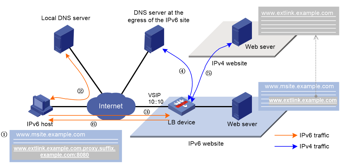
As shown in Figure 9, the working mechanism of external link proxy is as follows:
1. The IPv6 host executes the script file, and modifies the external link domain name as http://www.extlink.example.com.proxy.suffix.example.com.
2. The IPv6 host sends a DNS request to the local DNS server to query the domain name http://www.extlink.example.com.proxy.suffix.example.com. Based on the query result, the local DNS server notifies the IPv6 host of the LB device as the authoritative DNS server.
3. The IPv6 host sends a DNS request to the LB device to query the domain name http://www.extlink.example.com.proxy.suffix.example.com.
4. Upon receiving the DNS request, the LB device sends a DNS request to the DNS server to query the IPv4 address associated with the original domain name http://www.extlink.example.com.
5. The LB device obtains the resource associated with the external link based on the IPv4 address.
6. The LB device sends the obtained resource to the IPv6 host.
Rewriting the domain name
When the LB device detects an external link in the HTTP response from the server, it returns a script file for rewriting the external link. The client executes the script file and adds the specified parameters to the domain name of the external link. The parameters include the URI, domain name suffix, and virtual server port number. Upon receiving a DNS request containing the modified domain name, the LB device will request the associated IPv4 resource on behalf of the IPv6 client.
The format of the domain name after rewrite is protocol type://original domain name+URI+domain name suffix+:virtual server port number. The protocol type can be HTTP or HTTPS.
Suppose the protocol type is HTTP, domain name of the original external link is www.example.com, URI is proxy, domain name suffix is example.com, and virtual server port number is 8080. The external link domain name after rewrite is http://www.example.com.proxy.example.com:8080.
The device supports loading a custom script file for rewriting external links. If no custom script file is loaded, the default script file applies.
Restrictions and guidelines
Before configuring this feature, contact the server provider to configure the LB device as the authoritative DNS server on the local DNS server. This configuration enables the local DNS server to redirect DNS requests to the LB device for resolving modified domain names.
You must use the loadbalance dns-server command to specify a DNS server on the LB device to resolve original external link domain names. For more information about DNS server configuration, see "Configuring transparent DNS proxy."
If DNS packet link selection is performed by inbound link load balancing, make sure the domain name suffixes in DNS mappings are the same as those on the external link proxy.
Make sure the script file format is supported by the client browser. As a best practice, use the JS script file.
Make sure the name of the external link rewrite file is different from the response file for HTTP requests.
Procedure
1. Enter system view.
system-view
2. Enter HTTP virtual server view.
virtual-server virtual-server-name
3. Configure the URI for external link proxy.
external-link inject-uri string
By default, no URI is configured for external link proxy.
A URI is used to identify whether the domain name in a DNS request has been rewritten.
4. Configure the domain name suffix for external link proxy.
external-link inject-domain-suffix domain-suffix
By default, no domain name suffix is configured for external link proxy.
5. (Optional.) Specify the SNAT address pool for external link proxy.
external-link snat-pool pool-name
By default, no SNAT address pool is specified for external link proxy. The LB device uses the IP address of the output interface to the server as the client IP address.
Upon receiving a DNS request containing a modified domain name, the LB device extracts the original domain name and chooses an IP address from the specified SNAT pool. The LB device uses this IP address as the client IP address to initiate a request on behalf of the IPv6 client.
6. (Optional.) Add a domain name to the whitelist for external link proxy.
external-link inject-uri string
By default, no domain names are added to the whitelist for external link proxy.
The LB device does not rewrite the external links containing any domain names in the whitelist.
7. Enable external link proxy.
external-link proxy enable
By default, external link proxy is disabled.
8. Return to system view.
quit
9. (Optional.) Load an external link rewrite file.
loadbalance reload external-link file filename
By default, the default external link rewrite file is used.
If the file content has changed, you must reload the external link rewrite file to ensure it is effective.
Specifying a cluster traffic group for a virtual server
About this task
In a cluster network, a traffic group is the basic logical unit for processing services in the cluster. You can specify a cluster traffic group for a virtual server to enable the cluster traffic group to process the packets matching the virtual server. For more information about traffic groups, see RBM configuration in High Availability Configuration Guide.
Restrictions and guidelines
To specify a cluster traffic group for a virtual server, make sure the current device has been added to the traffic group.
Different types of virtual servers can use the same cluster traffic group.
If you execute this command multiple times, the most recent configuration takes effect.
Procedure
1. Enter system view.
system-view
2. Enter virtual server view.
virtual-server virtual-server-name
3. Specify a cluster traffic group for the virtual server.
traffic-group traffic-group-id
By default, no cluster traffic group is specified for a virtual server.
Enabling IP address advertisement for a virtual server
About this task
This feature can implement load balancing among data centers in a disaster recovery network. You must enable IP address advertisement for a virtual server on the LB device in each data center.
After this feature is configured, the device advertises the IP address of the virtual server to OSPF for route calculation. When the service of a data center switches to another data center, the traffic to the virtual server can also be switched to that data center. For information about OSPF, see Network Connectivity Configuration Guide.
Procedure
1. Enter system view.
system-view
2. Enter virtual server view.
virtual-server virtual-server-name
3. Enable IP address advertisement for the virtual server.
route-advertisement enable
By default, IP address advertisement is disabled for a virtual server.
Specifying an interface for sending gratuitous ARP packets and ND packets
About this task
Perform this task to specify an interface from which gratuitous ARP packets and ND packets are sent out. For information about gratuitous ARP, see ARP configuration in Network Connectivity Configuration Guide. For information about ND, see IPv6 basics configuration in Network Connectivity Configuration Guide.
If the virtual server IP address is in the same network segment as the IP address of an interface connected to a client, you must perform the following tasks:
· Set the IPv4 subnet mask length to 32 or IPv6 prefix length to 128 for the virtual server IP address.
· Specify an interface for sending gratuitous ARP or ND packets.
Procedure
1. Enter system view.
system-view
2. Enter virtual server view.
virtual-server virtual-server-name
3. Specify an interface for sending gratuitous ARP packets and ND packets.
arp-nd interface interface-type interface-number
By default, no interface is specified for sending gratuitous ARP packets and ND packets.
Enabling immediate TCP connection interruption upon virtual server unavailability
About this task
After you enable this feature for a virtual server, if the virtual server is unavailable, a SYN packet from a client will be immediately responded to with an RST packet.
Procedure
1. Enter system view.
system-view
2. Enter virtual server view.
virtual-server virtual-server-name
3. Enable immediate TCP connection interruption upon virtual server unavailability.
service-down-action reset
By default, immediate TCP connection interruption upon virtual server unavailability is disabled.
Inserting client source IP address into the X-Forwarded-For field
About this task
After you enable this feature, when the device receives a request packet from a client, it will insert the client source IP address into the X-Forwarded-For field in the HTTP packet extended header.
Procedure
1. Enter system view.
system-view
2. Enter HTTP virtual server view.
virtual-server virtual-server-name
3. Enable the device to insert client source IP address into the X-Forwarded-For field.
insert-xff enable
By default, the device does not insert client source IP address into the X-Forwarded-For field.
Enabling proxy protocol for a TCP virtual server
About this task
After you configure this feature, the device uses the proxy protocol to transparently transmit the real source IP address information to the back-end real server.
Restrictions and guidelines
If you do not specify a proxy protocol version when configuring this feature, version 1 is used by default. Before configuring this feature, make sure that the back-end real server supports the specified proxy protocol version. If the back-end real server does not support the specified proxy protocol version, the device and the real server cannot establish a connection.
Only Layer 7 TCP virtual servers support this feature.
Procedure
1. Enter system view.
system-view
2. Enter TCP virtual server view.
virtual-server virtual-server-name
3. Enable proxy protocol for the TCP virtual server.
proxy-protocol enable [ v1 | v2 ]
By default, proxy protocol is disabled for a TCP virtual server.
Configuring the content to be output by using the fast log output feature
About this task
Perform this task to configure the LB-related content to be output to the log host by using the fast log output feature. For information about the fast log output feature, see Network Management and Monitoring Configuration Guide.
Prerequisites
Before performing this task, you must enable fast log output for load balancing and configure fast log output parameters.
Procedure
1. Enter system view.
system-view
2. Enter HTTP virtual server view.
virtual-server virtual-server-name
3. Configure the content to be output by using the fast log output feature.
customlog content content-value
By default, no content is output by using the fast log output feature.
Enabling a virtual server
About this task
After you configure a virtual server, you must enable the virtual server to for it to work.
Procedure
1. Enter system view.
system-view
2. Enter virtual server view.
virtual-server virtual-server-name
3. Enable the virtual server.
service enable
By default, the virtual server is disabled.
Configuring an LB class
An LB class classifies packets by comparing packets against specific rules. Matching packets are further processed by LB actions. You can create a maximum of 65535 rules for an LB class.
LB class tasks at a glance
To configure an LB class, perform the following tasks:
1. Configuring a generic LB class
b. Creating a match rule
Choose the following tasks as needed:
- Creating a match rule that references an LB class
- Creating a source IP address match rule
- Creating an interface match rule
- Creating a user group match rule
- Creating a TCP payload match rule
2. Configuring a Diameter LB class
b. Creating a match rule
Choose the following tasks as needed:
- Creating a match rule that references an LB class
- Creating an application ID match rule
- Creating a destination realm match rule
3. Configuring an HTTP LB class
b. Creating a match rule
Choose the following tasks as needed:
- Creating a match rule that references an LB class
- Creating a source IP address match rule
- Creating an interface match rule
- Creating a user group match rule
- Creating an HTTP content match rule
- Creating an HTTP cookie match rule
- Creating an HTTP header match rule
- Creating an HTTP URL match rule
- Creating an HTTP method match rule
- Creating an HTTP version match rule
- Creating a RADIUS attribute match rule
4. Configuring a MySQL LB class
b. Configuring a match rule
Choose the following tasks as needed:
- Creating a match rule that references an LB class
- Creating a source IP address match rule
- Creating a MySQL statement match rule
5. Configuring a RADIUS LB class
b. Creating a match rule
Choose the following tasks as needed:
- Creating a match rule that references an LB class
- Creating a source IP address match rule
- Creating a RADIUS attribute match rule
Creating an LB class
Creating an LB class for Layer 4 server load balancing
1. Enter system view.
system-view
2. Create a generic LB class, and enter LB class view.
loadbalance class class-name type generic [ match-all | match-any ]
When you create an LB class, you must specify the class type. You can enter an existing LB class view without specifying the class type. If you specify the class type when entering an existing LB class view, the class type must be the one specified when you create the LB class.
3. (Optional.) Configure a description for the LB class.
description text
By default, no description is configured for the LB class.
Creating an LB class for Layer 7 server load balancing
1. Enter system view.
system-view
2. Create a Diameter, HTTP, MySQL, or RADIUS LB class, and enter LB class view.
loadbalance class class-name type { diameter | http | mysql | radius } [ match-all | match-any ]
When you create an LB class, you must specify an class type. You can enter an existing LB class view without specifying the class type. If you specify the class type when entering an existing LB class view, the class type must be the one specified when you create the LB class.
3. (Optional.) Configure a description for the LB class.
description text
By default, no description is configured for the LB class.
Creating a match rule that references an LB class
1. Enter system view.
system-view
2. Enter LB class view.
loadbalance class class-name
3. Create a match rule that references an LB class.
match [ match-id ] class class-name
Creating a source IP address match rule
1. Enter system view.
system-view
2. Enter LB class view.
loadbalance class class-name
3. Create a source IP address match rule.
match [ match-id ] source { ip address ipv4-address [ mask-length | mask ] | ipv6 address ipv6-address [ prefix-length ] }
Creating an ACL match rule
1. Enter system view.
system-view
2. Enter LB class view.
loadbalance class class-name
3. Create an ACL match rule.
match [ match-id ] acl [ ipv6 ] { acl-number | name acl-name }
Creating an interface match rule
1. Enter system view.
system-view
2. Enter generic or HTTP LB class view.
loadbalance class class-name
3. Create an interface match rule.
match [ match-id ] interface interface-type interface-number
Creating a user match rule
1. Enter system view.
system-view
2. Enter generic or HTTP LB class view.
loadbalance class class-name
3. Create a user match rule.
match [ match-id ] [ identity-domain domain-name ] user user-name
Creating a user group match rule
1. Enter system view.
system-view
2. Enter generic or HTTP LB class view.
loadbalance class class-name
3. Create a user group match rule.
match [ match-id ] [ identity-domain domain-name ] user-group user-group-name
Creating a TCP payload match rule
About this task
The device takes the corresponding LB action on TCP packets matching a TCP payload match rule. If you specify the not keyword for a TCP payload match rule, the device takes the corresponding LB action on TCP packets not matching the TCP payload match rule.
Procedure
1. Enter system view.
system-view
2. Enter generic LB class view.
loadbalance class class-name
3. Create a TCP payload match rule.
match [ match-id ] payload payload [ case-insensitive ] [ not ]
Creating an application ID match rule
About this task
The device takes the corresponding LB action on Diameter messages matching an application ID match rule.
Restrictions and guidelines
The specified application ID must be an application ID defined in the Diameter Base Protocol and its extension protocols. If the specified application ID does not exist, the rule does not take effect.
Procedure
1. Enter system view.
system-view
2. Enter Diameter LB class view.
loadbalance class class-name
3. Create an application ID match rule.
match [ match-id ] application-id [ application-id | all ]
Creating a destination realm match rule
About this task
If a Diameter LB class is configured with a destination realm name match rule, the corresponding LB action will be performed after the traffic matches the specified destination realm name. If the specified destination realm name does not exist, the rule does not take effect.
Procedure
1. Enter system view.
system-view
2. Enter Diameter LB class view.
loadbalance class class-name
3. Create a destination realm match rule.
match [ match-id ] destination-realm realm-name
Creating an HTTP content match rule
1. Enter system view.
system-view
2. Enter HTTP LB class view.
loadbalance class class-name
3. Create an HTTP content match rule.
match [ match-id ] content content [ offset offset ]
This command is not supported by virtual servers of the fast HTTP type.
Creating an HTTP cookie match rule
1. Enter system view.
system-view
2. Enter HTTP LB class view.
loadbalance class class-name
3. Create an HTTP cookie match rule.
match [ match-id ] cookie cookie-name value value
Creating an HTTP header match rule
1. Enter system view.
system-view
2. Enter HTTP LB class view.
loadbalance class class-name
3. Create an HTTP header match rule.
match [ match-id ] header header-name value value
Creating an HTTP URL match rule
1. Enter system view.
system-view
2. Enter HTTP LB class view.
loadbalance class class-name
3. Create an HTTP URL match rule.
match [ match-id ] url url
Creating an HTTP method match rule
1. Enter system view.
system-view
2. Enter HTTP LB class view.
loadbalance class class-name
3. Create an HTTP method match rule.
match [ match-id ] method { ext ext-type | rfc rfc-type }
Creating an HTTP version match rule
1. Enter system view.
system-view
2. Enter HTTP LB class view.
loadbalance class class-name
3. Create an HTTP method match rule.
match [ match-id ] version { 1.0 | 1.1 | 2.0 }
Creating a MySQL statement match rule
1. Enter system view.
system-view
2. Enter MySQL LB class view.
loadbalance class class-name
3. Create a MySQL statement match rule.
match [ match-id ] sql sql [ case-insensitive ] [ not ]
Creating a RADIUS attribute match rule
1. Enter system view.
system-view
2. Enter RADIUS LB class view.
loadbalance class class-name
3. Create a RADIUS attribute match rule.
match [ match-id ] radius-attribute { code attribute-code | user-name } value attribute-value
Configuring an LB action
About LB action modes
LB actions include the following modes:
· Forwarding mode—Determines whether and how to forward packets. If no forwarding action is specified, packets are dropped.
· Modification mode—Modifies packets. To prevent the LB device from dropping the modified packets, the modification action must be used together with a forwarding action.
· Response mode—Responds to client requests by using a file.
If you create an LB action without specifying any of the previous action modes, packets are dropped.
Restrictions and guidelines
For Layer 4 server load balancing, the following configurations are mutually exclusive:
· Configure the forwarding mode.
· Specify server farms.
For Layer 7 server load balancing, any two of the following configurations are mutually exclusive:
· Specify server farms.
· Configure the redirection feature.
· Specify a response file for matching HTTP requests.
For Layer 7 server load balancing, the following configurations are also mutually exclusive:
· Match the next rule upon failure to find a real server.
· Specify a response file used upon load balancing failure.
LB action tasks at a glance
To configure an LB action, perform the following tasks:
1. Configuring a generic LB action
b. (Optional.) Configuring a forwarding LB action
- Configuring the forwarding mode
You can configure only one of the "Configuring the forwarding mode", "Specifying server farms", and "Closing TCP connections" tasks.
- (Optional.) Matching the next rule upon failure to find a real server
- (Optional.) Closing TCP connections upon failure to find a real server
c. (Optional.) Configuring a modification LB action
Choose the following tasks as needed:
- Configuring the ToS field in IP packets sent to the server
2. Configuring a Diameter LB action
b. (Optional.) Configuring a forwarding LB action
You can configure only one of the "Specifying server farms" and "Closing TCP connections" tasks.
- (Optional.) Matching the next rule upon failure to find a real server
c. (Optional.) Configuring a modification LB action
Choose the following tasks as needed:
- Configuring the ToS field in IP packets sent to the server
- Specifying a parameter profile
- Specifying an SSL client policy
3. Configuring an HTTP LB action
b. (Optional.) Configuring a forwarding LB action
You can configure only one of the "Specifying server farms" and "Closing TCP connections" tasks.
- (Optional.) Matching the next rule upon failure to find a real server
- (Optional.) Closing TCP connections upon failure to find a real server
c. (Optional.) Configuring a modification LB action
Choose the following tasks as needed:
- Configuring the ToS field in IP packets sent to the server
- Rewriting the URL in the Location header of HTTP responses from the server
- Rewriting the content in the Location header of HTTP responses from the server
- Specifying an SSL client policy
- Rewriting the content of HTTP responses
- Configuring the HTTP redirection feature
d. (Optional.) Configuring a response LB action
- Specifying a response file for matching HTTP requests
- Specifying a response file used upon load balancing failure
e. (Optional.) Enabling external link proxy
4. Configuring a RADIUS LB action
b. (Optional.) Configuring a forwarding LB action
- Matching the next rule upon failure to find a real server
c. (Optional.) Configuring a modification LB action
- Configuring the ToS field in IP packets sent to the server
Creating an LB action
Creating an LB action for Layer 4 server load balancing
1. Enter system view.
system-view
2. Create a generic LB action, and enter LB action view.
loadbalance action action-name type generic
When you create an LB action, you must specify the action type. You can enter an existing LB action view without specifying the action type. If you specify the action type when entering an existing LB action view, the action type must be the one specified when you create the LB action.
3. (Optional.) Configure a description for the LB action.
description text
By default, no description is configured for the LB action.
Creating an LB action for Layer 7 server load balancing
1. Enter system view.
system-view
2. Create a Diameter, HTTP or RADIUS LB action, and enter LB action view.
loadbalance action action-name type { diameter | http | radius }
When you create an LB action, you must specify the action type. You can enter an existing LB action view without specifying the action type. If you specify the action type when entering an existing LB action view, the action type must be the one specified when you create the LB action.
3. (Optional.) Configure a description for the LB action.
description text
By default, no description is configured for the LB action.
Configuring a forwarding LB action
About this task
Three forwarding LB action types are available:
· Forward—Forwards matching packets.
· Specify server farms—When the primary server farm is available (contains available real servers), the primary server farm is used to guide packet forwarding. When the primary server farm is not available, the backup server farm is used to guide packet forwarding.
· Close TCP connections—Closes TCP connections matching the LB policy by sending FIN or RST packets.
· Match the next rule upon failure to find a real server—If the device fails to find a real server according to the LB action, it matches the packet with the next rule in the LB policy.
· Close TCP connections upon failure to find a real server—Closes TCP connections matching the LB policy by sending FIN or RST packets if the device fails to find a real server according to the LB action.
Configuring the forwarding mode
1. Enter system view.
system-view
2. Enter generic LB action view.
loadbalance action action-name
3. Configure the forwarding mode.
forward all
By default, the forwarding mode is to discard packets.
Specifying server farms
1. Enter system view.
system-view
2. Enter LB action view.
loadbalance action action-name
3. Specify server farms.
server-farm server-farm-name [ backup backup-server-farm-name ] [ sticky sticky-name [ backup backup-sticky-name ] ]
By default, no server farm is specified.
The device generates backup sticky entries for only the following sticky group combinations:
¡ RADIUS-type primary sticky group and port-address-type backup sticky group.
¡ HTTP cookie-type primary sticky group and port-address-type backup sticky group.
¡ HTTP cookie-type primary sticky group and HTTP passive-type backup sticky group.
Closing TCP connections
1. Enter system view.
system-view
2. Enter Diameter, generic, or HTTP LB action view.
loadbalance action action-name
3. Configure the method of closing TCP connections.
tcp-close { fin | rst }
By default, FIN packets are sent to close TCP connections.
Matching the next rule upon failure to find a real server
1. Enter system view.
system-view
2. Enter LB action view.
loadbalance action action-name
3. Match the next rule upon failure to find a real server.
fallback-action continue
By default, packets are discarded when no real servers are available for the current LB action.
Closing TCP connections upon failure to find a real server
1. Enter system view.
system-view
2. Enter generic or HTTP LB action view.
loadbalance action action-name
3. Configure the method of closing TCP connections upon failure to find a real server.
fallback-action close { fin | rst }
By default, packets are dropped when no real servers are available for the current LB action.
Configuring a modification LB action
Configuring the ToS field in IP packets sent to the server
1. Enter system view.
system-view
2. Enter LB action view.
loadbalance action action-name
3. Configure the ToS field in IP packets sent to the server.
set ip tos tos-number
By default, the ToS field in IP packets sent to the server is not changed.
Rewriting the TCP payload
1. Enter system view.
system-view
2. Enter TCP LB action view.
loadbalance action action-name
3. Rewrite the TCP payload.
payload rewrite { both | request | response } value value replace replace-string
By default, the TCP payload is not rewritten.
Only Layer 7 TCP virtual servers can reference an LB policy that contains this action.
Specifying a parameter profile
1. Enter system view.
system-view
2. Enter Diameter LB action view.
loadbalance action action-name
3. Specify a parameter profile.
parameter { diameter-session | tcp } profile-name [ server-side ]
By default, no parameter profile is specified.
Use this command to specify a Diameter session parameter profile to process the traffic forwarded to the server farm. Use this command to specify a TCP parameter profile to process and optimize the TCP connections established between the device and the server.
Handling the HTTP header
1. Enter system view.
system-view
2. Enter HTTP LB action view.
loadbalance action action-name
3. Delete an HTTP header.
header delete { both | request | response } name header-name
By default, the HTTP header is not deleted.
The device deletes the specified header from HTTP packets.
4. Insert an HTTP header.
header insert { both | request | response } name header-name value value [ encode { base64 | url } ]
By default, the HTTP header is not inserted.
The device inserts the specified header into HTTP packets.
5. Rewrite an HTTP header.
header rewrite { both | request | response } name header-name value value replace replace [ encode { base64 | url } ]
By default, the HTTP header is not rewritten.
The device rewrites the specified content of the matching header in HTTP packets as new content.
6. Rewrite the URL in HTTP requests.
header rewrite request url value value replace replace [ encode { base64 | url } ]
By default, the URL in HTTP requests is not rewritten.
Rewriting the URL in the Location header of HTTP responses from the server
1. Enter system view.
system-view
2. Enter HTTP LB action view.
loadbalance action action-name
3. Rewrite the URL in the Location header of HTTP responses from the server.
ssl url rewrite location location [ clearport clear-port ] [ sslport ssl-port ]
By default, the URL in the Location header of HTTP responses from the server is not rewritten.
If the Location header of an HTTP response packet contains the specified URL and HTTP port number, the system rewrites HTTP in the URL to HTTPS and rewrites the HTTP port number to an SSL port number.
Rewriting the content in the Location header of HTTP responses from the server
1. Enter system view.
system-view
2. Enter HTTP LB action view.
loadbalance action action-name
3. Rewrite the content in the Location header of HTTP responses from the server.
location rewrite match regex match-pattern replace replace-string
By default, the content in the Location header of HTTP responses from the server is not rewritten.
If the HTTP response contains 302 redirect and matches the regular expression of the specified Location header, the system will rewrite the content in the Location header to replace-value based on the the matched match-pattern.
As a best practice, configure a maximum of 16 rules for an HTTP LB action. If you execute this command multiple times to rewrite the same Location header content, the most recent configuration takes effect.
If this feature is configured multiple times to rewrite the same content of the Location header, the most recent configuration takes effect.
Redirection of the Location header is executed after SSL URL redirection rewrite. The system rewrites the Location header content after matching the SSL URL rewrite result.
Specifying an SSL client policy
1. Enter system view.
system-view
2. Enter Diameter or HTTP LB action view.
loadbalance action action-name
3. Specify an SSL client policy for the LB action.
ssl-client-policy policy-name
By default, the LB action does not reference any SSL client policies.
Specifying an SSL client policy enables the LB device (SSL client) to send encrypted traffic to an SSL server.
Rewriting the content of HTTP responses
1. Enter system view.
system-view
2. Enter HTTP LB action view.
loadbalance action action-name
3. Rewrite the content of HTTP responses.
content rewrite value value replace replace
By default, the content of HTTP responses is not rewritten.
Configuring the HTTP redirection feature
1. Enter system view.
system-view
2. Enter HTTP LB action view.
loadbalance action action-name
3. Enable the HTTP redirection feature and specify a redirection URL for the LB action.
redirect relocation relocation
By default, the HTTP redirection feature is disabled for an LB action.
This feature redirects all HTTP request packets matching an LB action to the specified URL.
4. Specify the redirection status code that the LB device returns to a client.
redirect return-code { 301 | 302 | 307 }
By default, the redirection status code that the LB device returns to a client is 302.
This command takes effect only when the HTTP redirection feature is enabled for an LB action.
Specifying a response file for matching HTTP requests
About this task
If the URL path in a client request matches the specified URL path, the device responds to the request by using an uncompressed file.
If the URL path in a client request matches the specified working path plus a relative path in the specified zip file, the device responds to the request by using the file in the zip file.
If you configure both an uncompressed file and a compressed file for the same URL path, the uncompressed file is used to respond to matching HTTP requests.
Procedure
1. Enter system view.
system-view
2. Enter HTTP LB action view.
loadbalance action action-name
3. Specify a response file for matching HTTP requests.
response { url url file filename | workpath workpath zip-file zip-filename }
By default, no response file is specified for HTTP requests.
Specifying a response file used upon load balancing failure
About this task
This feature enables the device to respond to client requests when the device fails to find an available real server or fails to find the response file specified in the response command.
Restrictions and guidelines
The response file specified in this feature must contain a complete HTTP packet and cannot contain only the HTTP content.
Procedure
1. Enter system view.
system-view
2. Enter HTTP LB action view.
loadbalance action action-name
3. Specify a response file used upon load balancing failure.
fallback-action response raw-file raw-filename
By default, packets are discarded upon load balancing failure.
Enabling external link proxy
About this task
To perform external link proxy for a traffic class instead of all traffic of a virtual server, enable external link proxy in an HTTP LB action. Additionally, configure external link proxy parameters in the view of the virtual server (see "Configuring external link proxy") and specify the LB policy for the virtual server.
The external link proxy action is first taken when the following actions are also configured:
· A forwarding LB action (see "Configuring a forwarding LB action").
· HTTP redirection action (see "Configuring the HTTP redirection feature").
· Specifying a response file for matching HTTP requests (see "Specifying a response file for matching HTTP requests").
· Specifying a response file used upon load balancing failure (see "Specifying a response file used upon load balancing failure").
Procedure
1. Enter system view.
system-view
2. Enter HTTP LB action view.
loadbalance action action-name
3. Enable external link proxy.
external-link proxy enable
By default, external link proxy is disabled.
Configuring an LB policy
About configuring an LB policy
An LB policy associates an LB class with an LB action to guide packet forwarding. In an LB policy, you can configure an LB action for packets matching the specified LB class, and configure the default action for packets matching no LB class.
You can specify multiple LB classes for an LB policy. Packets match the LB classes in the order the LB classes are configured. If an LB class is matched, the specified LB action is performed. Therefore, when multiple LB classes overlap, place the more detailed LB classes at the front and the general ones at the back. If no LB class is matched, the default LB action is performed.
LB policy tasks at a glance
The LB policy configuration tasks for Layer 4 and Layer 7 server load balancing are the same.
To configure an LB policy, perform the following tasks:
3. Specifying the default LB action
Creating an LB policy
Creating an LB policy for Layer 4 server load balancing
1. Enter system view.
system-view
2. Create a generic LB policy, and enter LB action view.
loadbalance policy policy-name type generic
When you create an LB policy, you must specify the policy type. You can enter an existing LB policy view without specifying the policy type. If you specify the policy type when entering an existing LB policy view, the policy type must be the one specified when you create the LB policy.
3. (Optional.) Configure a description for the LB policy.
description text
By default, no description is configured for the LB policy.
Creating an LB policy for Layer 7 server load balancing
1. Enter system view.
system-view
2. Create a Diameter, HTTP, or RADIUS LB policy, and enter LB policy view.
loadbalance policy policy-name type { diameter | http | mysql | radius }
When you create an LB policy, you must specify the policy type. You can enter an existing LB policy view without specifying the policy type. If you specify the policy type when entering an existing LB policy view, the policy type must be the one specified when you create the LB policy.
3. (Optional.) Configure a description for the LB policy.
description text
By default, no description is configured for the LB policy.
Specifying an LB action
Restrictions and guidelines
A generic LB policy can reference only generic LB classes and generic LB actions. An HTTP LB policy can reference HTTP or generic LB classes and LB actions. A MySQL LB policy can reference MySQL or generic LB classes and generic LB actions. A RADIUS LB policy can reference RADIUS or generic LB classes and LB actions.
Procedure
1. Enter system view.
system-view
2. Enter LB policy view.
loadbalance policy policy-name
3. Specify an LB action for the specified LB class.
class class-name [ insert-before before-class-name | insert-after [ after-class-name ] ] action action-name
By default, no LB action is specified for any LB classes.
You can specify the same LB action for different LB classes.
Specifying the default LB action
Restrictions and guidelines
A generic LB policy can only reference generic LB actions. This rule does not apply to HTTP LB policies.
Procedure
1. Enter system view.
system-view
2. Enter LB policy view.
loadbalance policy policy-name
3. Specify the default LB action.
default-class action action-name
By default, no default LB action is specified.
Configuring a sticky group
A sticky group is a technique that optimizes traffic distribution and enhances processing efficiency. It distributes traffic with the same attributes to the same real server, ensuring continuity of user sessions and reduces repeated calculations of scheduling algorithms.
When a device receives an access request with specific attributes for the first time, it generates a sticky entry based on the configured sticky method. Before this sticky entry ages, the device uses it to directly forward subsequent requests from the same user to the previously selected real server without performing repeated scheduling algorithm calculations.
For example, on a shopping website, each user generates multiple requests when they browse products, add items to the cart, and check out. If each request is processed by a different server, data inconsistency issues might occur with multiple accesses. Using a sticky group can ensure that all requests from the same user are processed by the same server, which helps ensure data consistency and smooth user experience.
The device processes user requests as follows:
1. Upon receiving a user request with certain attributes, the device assigns the request to a real server according to the scheduling algorithm, and generates a sticky entry.
2. Before the sticky entry ages, if the device receives a user request with the same attributes again, it directly forwards the request to the previously selected real server without performing repeated scheduling calculations.
A sticky method serves as the basis for generating sticky entries. You can specify a sticky method in a sticky group as needed.
Restrictions and guidelines
To have a configured sticky group take effect, perform any of the following operations:
· In virtual server view, specify the sticky group for the default server farm. For more information, see "Specifying server farms."
· In LB action view, specify the sticky group for a server farm. For more information, see "Specifying server farms."
· In HTTP virtual server view, specify the HTTP cookie sticky group. For more information, see "Specifying a sticky group."
The sticky group specified for the virtual server has the highest priority. The devices generates sticky entries preferentially based on the sticky group specified for the virtual server.
You can specify both a primary sticky group and a backup sticky group for a server farm. The device generates both primary and backup sticky entries based on two sticky groups. When new traffic fails to match the primary sticky entry, the device uses the backup sticky entry to match traffic.
If a backup sticky group is configured, the device generates backup sticky entries for only the following sticky group combinations:
· RADIUS-type primary sticky group and address- and port-type backup sticky group.
· HTTP cookie-type primary sticky group and address- and port-type backup sticky group.
· HTTP cookie-type primary sticky group and HTTP passive-type backup sticky group.
Licensing requirements for sticky groups
You must install a license before you can use the Diameter, HTTP content, HTTP cookie, HTTP header, HTTP passive, HTTP payload, RADIUS/SIP/SSL/TCP payload, or UDP passive sticky group. For more information about licenses, see license management in Fundamentals Configuration Guide.
Sticky group tasks at a glance
2. Configuring stickiness
Choose the following tasks as needed, and configure a minimum of one sticky method for a sticky group.
¡ Configuring address- and port-type stickiness
¡ Configuring RADIUS stickiness
¡ Configuring Diameter stickiness
3. (Optional.) Configuring the timeout timer for sticky entries
4. (Optional.) Configuring the match scope for sticky entries
5. (Optional.) Ignoring the limits for sessions that match sticky entries
6. (Optional.) Enabling stickiness-over-busyness
Creating a sticky group
About this task
Before configuring a sticky group, you must first create the sticky group. The device supports creating the following types of sticky groups:
· Layer 4 server load balancing—Address- and port-type sticky group.
· Layer 7 server load balancing—Diameter, HTTP entity, HTTP cookie, HTTP header, HTTP passive, HTTP/UDP payload, RADIUS, SIP, SSL, TCP payload, and UDP passive sticky group.
Restrictions and guidelines
When you create a sticky group, you must specify the group type. You can enter an existing sticky group view without specifying the group type. If you specify the group type when entering an existing sticky group view, the group type must be the one specified when you create the sticky group.
Creating a sticky group for Layer 4 server load balancing
1. Enter system view.
system-view
2. Create an address- and port-type sticky group and enter sticky group view.
sticky-group group-name type address-port
3. (Optional.) Configure a description for the sticky group.
description text
By default, no description is configured for the sticky group.
Creating a sticky group for Layer 7 server load balancing
1. Enter system view.
system-view
2. Create a sticky group of the Diameter, HTTP content, HTTP cookie, HTTP header, HTTP/UDP payload, RADIUS, SIP, or SSL type and enter sticky group view.
sticky-group group-name type { diameter | http-content | http-cookie | http-header | http-passive | payload | radius | sip | ssl | tcp-payload | udp-passive }
3. (Optional.) Configure a description for the sticky group.
description text
By default, no description is configured for the sticky group.
Configuring address- and port-type stickiness
About this task
The device generates sticky entries based on the source IP address, source port, destination IP address, or destination port of user requests.
Procedure
1. Enter system view.
system-view
2. Enter address- and port-type sticky group view.
sticky-group group-name [ type address-port ]
When you create a sticky group, you must specify the group type. You can enter an existing sticky group view without specifying the group type. If you specify the group type when entering an existing sticky group view, the group type must be the one specified when you create the sticky group.
3. Configure the IP sticky method.
IPv4:
ip [ port ] { both | destination | source } [ mask mask-length ]
IPv6:
ipv6 [ port ] { both | destination | source } [ prefix prefix-length ]
By default, no IP sticky method is configured.
Configuring TCP stickiness
About this task
The device generates sticky entries based on specified portion of the TCP payload. This method allows the device to identify and obtain information from specific data segments in TCP flows and maintain session continuity based on that information.
Procedure
1. Enter system view.
system-view
2. Enter sticky group view.
sticky-group group-name [ type tcp-payload ]
When you create a sticky group, you must specify the group type. You can enter an existing sticky group view without specifying the group type. If you specify the group type when entering an existing sticky group view, the group type must be the one specified when you create the sticky group.
3. Configure the TCP payload sticky method.
payload [ offset offset ] [ start start-string ] [ end end-string | length length ]
By default, no TCP sticky method is configured.
Configuring UDP stickiness
About this task
The UDP sticky method generates sticky entries based on the payload of UDP request or response packets to ensure user session continuity. You can configure the following UDP sticky methods:
· UDP payload sticky method—The device generates sticky entries based on the specified portion of the payload in the UDP request packet. This method allows the device to identify and obtain information from specific data segments in UDP flows and maintain session continuity based on that information.
· UDP passive sticky method—After you configure the UDP passive sticky method, the device performs the following operations in sequence:
¡ Processes the response packet—When the device receives a UDP response packet for the first time, the system obtains the payload information from the UDP response packet based on the configuration of the payload get command. It uses this information to generate a sticky entry that record specific payload attributes for identifying traffic with the same attributes.
¡ Matches and forwards request packets—For subsequent UDP request packets received, the device obtains the specified payload information from the packets based on the configuration of the payload match command. If the payload information matches the information in the sticky entry, the devices forwards the request to the corresponding real server based on the sticky entry.
The UDP passive sticky method ensures that the device can continuously forward all requests associated with a specific session to the same server, thereby maintaining session continuity and data consistency.
Restrictions and guidelines
The UDP passive sticky method requires configuring both get and match commands.
Configuring a UDP payload sticky group
1. Enter system view.
system-view
2. Enter the UDP payload sticky group view.
sticky-group group-name [ type payload ]
When you create a sticky group, you must specify the group type. You can enter an existing sticky group view without specifying the group type. If you specify the group type when entering an existing sticky group view, the group type must be the one specified when you create the sticky group.
3. Configure the UDP payload sticky method.
payload [ offset offset ] [ start start-string ] [ end end-string | length length ]
By default, the UDP payload sticky method is not configured.
Configuring a UDP passive sticky group
1. Enter system view.
system-view
2. Enter UDP passive sticky group view.
sticky-group group-name [ type udp-passive ]
When you create a sticky group, you must specify the group type. You can enter an existing sticky group view without specifying the group type. If you specify the group type when entering an existing sticky group view, the group type must be the one specified when you create the sticky group.
3. Configure the UDP passive sticky method.
payload get [ offset offset ] [ start start-string ] [ end end-string | length length ]
payload match [ offset offset ] [ start start-string ] [ end end-string | length length ]
By default, no UDP passive sticky method is configured.
Configuring HTTP stickiness
About this task
The HTTP sticky method generates sticky entries based on different portions of HTTP packets to ensure session continuity. These portions include the HTTP request header, HTTP request entity, HTTP cookie, HTTP payload, HTTP response header, and HTTP response entity. You can configure the following sticky methods:
· HTTP header sticky method—Generates sticky entries based on the header information of HTTP requests, such as the Request-Method and custom header fields. This method ensures that all client requests with the same header value are forwarded to the same real server.
For example, you can use the Request-Method field to generate sticky entries. HTTP request methods, such as GET, POST, PUT, and DELETE, define the actions to be executed on a given resource. The device can generate sticky entries based on different request methods, and forward all requests with the same method to the same server.
For example, a GET request consumes less server performance, while a POST request involves data writing and complex backend logic. Under these circumstances, you can forward all GET requests to servers with lower processing capabilities, while directing POST requests to servers with more resources. This optimizes server load balancing based on the performance of real servers.
· HTTP entity sticky method—Generates sticky entries based on the entity portion of HTTP requests (request body). This method applies to the POST and PUT requests.
· HTTP cookie sticky method—Uses cookie information in HTTP requests to generate sticky entries. The device supports the following operations:
¡ Cookie get—Obtains specific cookie information from HTTP packets and generates sticky entries based on the cookie information. The server sets cookies by using the Set-Cookie field, the client browser stores these cookies and send them back to the server in subsequent requests, and the SLB device intercepts the cookies in requests to maintain session continuity between the user and the server.
¡ Cookie insert—Implements stickiness by modifying the actual server response. After the SLB device selects a real server to process user requests for the first time, it inserts a special Set-Cookie field into the HTTP response from that server. This field contains a unique identifier pointing to the real server.
¡ Cookie rewrite—Implements stickiness by modifying the actual server response. The device modifies the existing Set-Cookie header field in the HTTP response from the real server for storing the updated cookie on the client. After the SLB device selects a real server to process user requests for the first time, it modifies the cookie value or other attributes based on preconfigured rules. For example, an administrator can add the HttpOnly attribute to all Set-Cookie header fields. When the client stores this cookie, it cannot be accessed through the client JavaScript, which enhances session security.
· HTTP payload sticky method—This method is similar to the HTTP entity sticky method but applies more broadly to the payload of HTTP requests, including the URL, HTTP header, and body content. This method generates sticky entries based on the specified content of the entire HTTP request.
· HTTP passive sticky methods—Include HTTP header passive sticky method and HTTP entity passive sticky method.
¡ HTTP header passive sticky method—Creates a sticky entry based on the HTTP header information in the received HTTP response. This method enables the real server to determine the target real server for subsequent requests based on the returned response header. The method is applicable to the scenarios where the HTTP response header contains session control information, such as session ID included in the Set-Cookie header.
¡ HTTP entity passive sticky method—Uses the information in the response entity (body of the response packet) to generate sticky entries. This method applies when the HTTP response packet contains critical session information, such as dynamically generated tokens.
After you configure the HTTP passive sticky method, the device generates sticky entries by obtaining specific character strings from the header or entity of HTTP response packets based on the header get or content get command. For all subsequent HTTP requests received, the device uses the header match or content match command to obtain the specified field from the header or entity of the HTTP request packets. If this field matches a sticky entry, the device forwards the request according to that entry.
Both the HTTP passive header sticky method and the HTTP entity passive sticky method involve the get and match commands. Follow these guidelines when you configure the commands:
· Use n get commands to obtain n character strings. Any 1 to n of these strings can be combined in ID order to form 2n-1 character strings. If the character string obtained from the match command matches any of these combinations, the match is successful.
· Use n match commands to obtain n character strings, which are combined in ID order to create one character string for matching.
Assume that three get commands with IDs 1, 2, and 3 are configured. The device can obtain character strings a, b, and c from the HTTP response packet header. It then combines these strings to form seven character strings, namely a, b, c, ab, ac, bc, and abc, and generates seven sticky entries. In addition, three match commands with IDs 2, 3, and 4 are configured. After the device receives an HTTP request, if it obtains character strings a, b, and c based on these rules, and the combined string abc matches the string abc obtained through the get command, the HTTP request successfully matches the sticky entry and is forwarded according to the sticky entry.
Restrictions and guidelines
When you create a sticky group, you must specify the group type. You can enter an existing sticky group view without specifying the group type. If you specify the group type when entering an existing sticky group view, the group type must be the one specified when you create the sticky group.
The HTTP passive sticky method requires configuring both the get and match commands to create and match sticky entries.
For the same HTTP passive sticky group, you can configure a maximum of four get commands to obtain four specific character strings from the HTTP response packets. Similarly, you can configure a maximum of to four match commands to obtain four specific character strings from the HTTP request packets.
Configuring an HTTP header sticky group
1. Enter system view.
system-view
2. Enter HTTP header sticky group view.
sticky-group group-name [ type http-header ]
3. Configure the HTTP header sticky method.
header { { { host | name header-name | url } [ offset offset ] [ start start-string] [ end end-string | length length ] } | request-method | version }
By default, the HTTP header sticky method is not configured.
Configuring an HTTP entity sticky group
system-view
2. Enter HTTP entity sticky group view.
sticky-group group-name [ type http-content ]
3. Configure the HTTP content sticky method.
content [ offset offset ] [ start start-string ] [ end end-string | length length ]
By default, no HTTP content sticky method is configured.
This command is not supported by the virtual servers of the fast HTTP type.
Configuring an HTTP cookie sticky group
1. Enter system view.
system-view
2. Enter HTTP cookie sticky group view.
sticky-group group-name [ type http-cookie ]
3. Configure the HTTP cookie sticky method.
cookie { get name cookie-name [ offset offset ] [ start start-string] [ end end-string | length length ] | { insert [ name cookie-name ] [ domain domain-name ] [ path path ] [ httponly ] [ secure ] | rewrite [ name cookie-name ] [ httponly ] [ secure ] }
By default, the HTTP cookie sticky method is not configured.
4. (Optional.) Specify the name of the secondary cookie to be searched in the URI.
cookie secondary name value
By default, the name of the secondary cookie to be searched in the URI is not specified.
5. (Optional.) Enable checking for all packets.
check all-packet
By default, the checking for all packets is disabled.
Configuring an HTTP payload sticky group
1. Enter system view.
system-view
2. Enter HTTP payload sticky group view.
sticky-group group-name [ type payload ]
3. Configure the HTTP payload sticky method.
payload [ offset offset ] [ start start-string ] [ end end-string | length length ]
By default, the HTTP payload sticky method is not configured.
This command is not supported by the virtual servers of the fast HTTP type.
Configuring an HTTP passive sticky group
1. Enter system view.
system-view
2. Enter HTTP passive sticky group view.
sticky-group group-name [ type http-passive ]
3. Configure HTTP passive sticky methods. Choose the options to configure as needed:
¡ Configure the HTTP header passive sticky method.
header get id name header-name start start-string { end end-string | length length }
header match id { name header-name | url } start start-string { end end-string | length length }
By default, the HTTP header passive sticky method is not configured.
¡ Configure the HTTP entity passive sticky method.
content get id start start-string { end end-string | length length }
content match id start start-string { end end-string | length length }
By default, the HTTP entity passive sticky method is not configured.
4. (Optional.) Enable checking for all packets.
check all-packet
By default, the checking for all packets is disabled.
Configuring RADIUS stickiness
About this task
The device can generate sticky entries based on RADIUS attributes. When the device receives a RADIUS request, it checks the RADIUS attribute value. If the request matches a sticky entry, the device forwards the request to the RADIUS server recorded in the sticky entry for processing.
For example, employees who often work remotely or travel for business might need to frequently connect to and disconnect from the company's VPN service. Generating sticky entries with User-Name as the key attribute can ensure that all RADIUS requests based on the same username are forwarded to the RADIUS server that initially processed the user's request. This can enhance the efficiency and consistency of the authentication process.
Procedure
1. Enter system view.
system-view
2. Enter RADIUS sticky group view.
sticky-group group-name [ type radius ]
When you create a sticky group, you must specify the group type. You can enter an existing sticky group view without specifying the group type. If you specify the group type when entering an existing sticky group view, the group type must be the one specified when you create the sticky group.
3. Configure the RADIUS attribute sticky method.
radius-attribute { code attribute-code | framed-ip-address | user-name }
By default, no RADIUS attribute sticky method is configured.
Configuring Diameter stickiness
About this task
The Diameter attribute sticky methods apply only to Diameter messages.
Perform this task to configure the device to generate a sticky entry based on the specified Diameter attribute in a Diameter request. Subsequent requests that match the sticky entry are forwarded according to the sticky entry.
Restrictions and guidelines
Common Diameter attribute codes include:
· 258—Auth-Application-Id.
· 259—Acct-Application-Id.
· 263—Session-Id.
· 264—Origin-Host.
· 283—Destination-Realm.
· 293—Destination-Host.
· 296—Origin-Realm.
· 443—Subscription-Id.
· 444—Subscription-Id-Data.
You can configure only one Diameter attribute sticky method for a Diameter sticky group. If you perform this task multiple times, the most recent configuration takes effect.
Procedure
1. Enter system view.
system-view
2. Enter Diameter sticky group view.
sticky-group group-name [ type diameter ]
When you create a sticky group, you must specify the group type. You can enter an existing sticky group view without specifying the group type. If you specify the group type when entering an existing sticky group view, the group type must be the one specified when you create the sticky group.
3. Configure the Diameter sticky method.
diameter-attribute { code attribute-code [ index index-value ] } &<1-4>
By default, no Diameter sticky method is configured.
When the type of the AVP specified by the attribute-code argument is Grouped, which indicates that the attribute is an AVP sequence, you must also specify the index value of the attribute in the AVP sequence. If you do not specify the index-value argument, the index value takes 0.
Configuring SIP stickiness
About this task
SIP stickiness allows the device to generate sticky entries based on the Call ID header field in SIP messages. Packets with the same call ID are assigned to the same real server.
Procedure
1. Enter system view.
system-view
2. Enter SIP sticky group view.
sticky-group group-name [ type sip ]
When you create a sticky group, you must specify the group type. You can enter an existing sticky group view without specifying the group type. If you specify the group type when entering an existing sticky group view, the group type must be the one specified when you create the sticky group.
3. Configure the SIP call ID sticky method.
header call-id
By default, no SIP call ID sticky method is configured.
Configuring SSL stickiness
About this task
SSL stickiness ensures session consistency for SSL/TLS encrypted connections based on SSL session ID. The sticky method based on SSL session ID allows the system to identify and reuse existing sessions with the same session ID, avoiding repeated handshake processes. This reduces latency, improves efficiency, and enhances connection security.
Procedure
1. Enter system view.
system-view
2. Enter SSL sticky group view.
sticky-group group-name [ type ssl ]
When you create a sticky group, you must specify the group type. You can enter an existing sticky group view without specifying the group type. If you specify the group type when entering an existing sticky group view, the group type must be the one specified when you create the sticky group.
3. Configure the SSL sticky method based on SSL session ID.
ssl session-id
By default, no SSL sticky method is configured.
Configuring the timeout timer for sticky entries
About this task
This feature allows you to flexibly adjust the timeout timer for sticky entries. The timeout timer defines the maximum time a sticky entry can remain active before it is automatically removed. A correct timeout timer configuration can ensure session persistence while avoiding resource waste and potential performance bottlenecks.
Different types of sticky groups might require various timeout timer settings. For applications that require state persistence for a long time, such as HTTP cookie, set a longer timeout timer. For services that require quick state updates, such as the Diameter protocol, set a shorter timeout timer.
Procedure
1. Enter system view.
system-view
2. Enter sticky group view.
sticky-group group-name [ type { address-port | diameter | http-content | http-cookie | http-header | http-passive | payload | radius | sip | ssl | tcp-payload | udp-passive } ]
When you create a sticky group, you must specify the group type. You can enter an existing sticky group view without specifying the group type. If you specify the group type when entering an existing sticky group view, the group type must be the one specified when you create the sticky group.
3. Configure the timeout timer for sticky entries.
timeout { indefinite | timeout-value }
By default, the timeout timer for sticky entries is 86400 seconds for sticky groups of the HTTP cookie, HTTP passive, and UDP passive types, 180 seconds for Diameter sticky groups, and 60 seconds for sticky groups of other types.
Configuring the match scope for sticky entries
About this task
By default, the device uses sticky entries of a virtual server to match only traffic of that virtual server. You can perform this task to enlarge the match scope for sticky entries as follows:
· Match across services—If the device fails to find a matching sticky entry of the current virtual server, it continues to match the traffic against the sticky entries of other virtual servers with the same IP address but different port numbers. This match method is applicable when multiple virtual servers with the same IP address and different port numbers share the same real servers.
· Match across virtual servers—If the device fails to find a matching sticky entry of the current virtual server, it continues to match the traffic against the sticky entries of all other virtual servers. This match method is applicable when multiple virtual servers share the same real servers.
If both match methods are configured, matching across services have a higher priority. For each match scope, the most recent sticky entries are preferentially used to match traffic.
For example, three virtual servers exist and they all use the source IP sticky method. The generated sticky entries are shown in Figure 10 (only part of the entry information is displayed). Table 1 shows the different match results of different match scopes.
Figure 10 Sticky entry matching
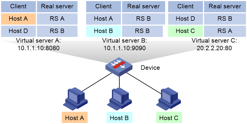
Table 1 Match result of each match scope
|
Match scope |
Match result |
|
Matching within the current virtual server |
The device matches the source IP address of requests against the sticky entry of virtual server A. · A match is found for host A, and the request from host A is distributed to real server A. · No matches are found for host B and host C, and the requests from host B and host C are distributed according the scheduling algorithm or LB policy. |
|
Matching across services |
The device matches the source IP address of requests against the sticky entry of virtual server A. · A match is found for host A, and the request from host A is distributed to real server A. · No matches are found for host B and host C, and the device continues to match the requests against the sticky entry of virtual server B. ¡ A match is found for host B, and the request from host B is distributed to real server B. ¡ No match is found for host C, and the request from host C is distributed according the scheduling algorithm or LB policy. |
|
Matching across virtual servers |
The device matches the source IP address of requests against the sticky entry of virtual server A. · A match is found for Host A, and the request from Host A is distributed to real server A. · No matches are found for host B and host C, and the device continues to match the requests against the sticky entries of virtual server B and virtual server C. ¡ A match is found for host B in virtual server B, and the request from host B is distributed to real server B. ¡ A match is found for host C in virtual server C, and the request from host C is distributed to real server A. |
Procedure
1. Enter system view.
system-view
2. Enter address and port, Diameter, or RADIUS sticky group view.
sticky-group group-name [ type { address-port | diameter | radius } ]
When you create a sticky group, you must specify the group type. You can enter an existing sticky group view without specifying the group type. If you specify the group type when entering an existing sticky group view, the group type must be the one specified when you create the sticky group.
3. Enable cross-service matching for sticky entries.
match-across-service enable
By default, cross-service matching for sticky entries is disabled.
4. Enable cross-virtual-server matching for sticky entries.
match-across-virtual-server enable
By default, cross-virtual-server matching for sticky entries is disabled.
Ignoring the limits for sessions that match sticky entries
About this task
Perform this task to ignore the following limits for sessions that match sticky entries:
· Bandwidth and connection parameters on real servers.
· LB connection limit policies on virtual servers.
Restrictions and guidelines
This feature is not supported by Diameter sticky groups.
Procedure
1. Enter system view.
system-view
2. Enter sticky group view.
sticky-group group-name [ type { address-port | http-content | http-cookie | http-header | http-passive | payload | radius | sip | ssl | tcp-payload | udp-passive } ]
When you create a sticky group, you must specify the group type. You can enter an existing sticky group view without specifying the group type. If you specify the group type when entering an existing sticky group view, the group type must be the one specified when you create the sticky group.
3. Ignore the limits for sessions that match sticky entries.
override-limit enable
By default, the session limits apply to sessions that match sticky entries.
Enabling stickiness-over-busyness
About this task
This feature enables the device to assign client requests to real servers based on sticky entries, regardless of whether the real servers are busy.
When this feature is disabled, the device assigns client requests to only real servers in normal state.
Restrictions and guidelines
This feature is not supported by Diameter sticky groups.
Procedure
1. Enter system view.
system-view
2. Enter sticky group view.
sticky-group group-name [ type { address-port | http-content | http-cookie | http-header | http-passive | payload | radius | sip | ssl | tcp-payload | udp-passive } ]
When you create a sticky group, you must specify the group type. You can enter an existing sticky group view without specifying the group type. If you specify the group type when entering an existing sticky group view, the group type must be the one specified when you create the sticky group.
3. Enable stickiness-over-busyness.
sticky-over-busy enable
By default, stickiness-over-busyness is disabled.
Configuring a parameter profile
A parameter profile typically preprocesses traffic entering the virtual server. It adjusts the incoming traffic based on the specified rules and settings. Such adjustments include setting the ToS field in IP packets, modifying TCP connection parameters, and applying specific processing rules to HTTP requests.
To have a configured parameter profile take effect, typically you must specify the profile in the virtual server configuration. Upon receiving client requests, the virtual server processes the traffic based on the specified parameter template. Parameter profile configuration not only enhances the configuration consistency, but also improves the flexibility and manageability of network services.
Licensing requirements for parameter profiles
You must install a license before you can use the Diameter-session, HTTP, HTTP/2, HTTP compression, MySQL, HTTP statistics, OneConnect, or TCP-application parameter profile. For more information about licenses, see license management in Fundamentals Configuration Guide.
Parameter profile tasks at a glance
To configure a parameter profile, perform the following tasks:
1. Creating a parameter profile
2. Configuring an IP parameter profile
¡ Configuring the ToS field in IP packets sent to the client
3. Configuring a TCP parameter profile
Choose the following tasks as needed:
¡ Configuring TCP connection parameters
¡ Setting the MSS for the LB device
¡ Configuring parameters for the specified TCP options
¡ Checking the TCP checksum of a received packet
¡ Configuring the TCP option for SNAT
¡ Configuring the threshold for triggering SYN Cookie protection
4. Configuring a TCP application parameter profile
¡ Configuring the TCP payload match parameters
5. Configuring a Diameter session parameter profile
Choose the following tasks as needed:
¡ Configuring Diameter capability exchange
¡ Configuring Diameter message retransmission
6. Configuring an HTTP parameter profile
Choose the following tasks as needed:
¡ Enabling load balancing for each HTTP request
¡ Configuring connection reuse between the LB device and the server
¡ Modifying the header in each HTTP request or response
¡ Disabling case sensitivity matching for HTTP
¡ Configuring the maximum length to parse the HTTP content
¡ Configuring secondary cookie parameters
¡ Specifying the action to take when the header of an HTTP packet exceeds the maximum length
¡ Configuring the maximum size of the HTTP content
¡ Configuring the cookie encryption feature
7. Configuring an HTTP-compression parameter profile
¡ Configuring the HTTP compression feature
8. Configuring an HTTP-statistics parameter profile
¡ Configuring the HTTP statistics feature
9. Configuring an HTTP2.0 parameter profile
¡ Configuring an HTTP2.0 parameter profile
10. Configuring a MySQL parameter profile
¡ Configuring connection reuse between the LB device and the server
Creating a parameter profile
About this task
You must create a parameter profile before configuring parameter profile settings. The device supports creating the following parameter profiles:
· IP parameter profile for Layer 4 server load balancing.
· Diameter-session, HTTP, HTTP compression, MySQL, HTTP statistics, HTTP/2, MySQL, OneConnect, TCP, and TCP-application parameter profiles for Layer 7 server load balancing.
Restrictions and guidelines
When you create a parameter profile, you must specify the profile type. You can enter an existing parameter profile view without specifying the profile type. If you specify the profile type when entering an existing parameter profile view, the profile type must be the one specified when you create the parameter profile.
Creating a parameter profile for Layer 4 server load balancing
1. Enter system view.
system-view
2. Create an IP parameter profile and enter parameter profile view.
parameter-profile profile-name type ip
3. (Optional.) Configure a description for the parameter profile.
description text
By default, no description is configured for the parameter profile.
Creating a parameter profile for Layer 7 server load balancing
1. Enter system view.
system-view
2. Create a parameter profile of the Diameter session, HTTP, HTTP-compression, HTTP-statistics, HTTP2.0, MySQL, OneConnect, TCP, or TCP-application type and enter parameter profile view.
parameter-profile profile-name type { diameter-session | http | http-compression | http-statistics | http2 | mysql | oneconnect | tcp | tcp-application }
3. (Optional.) Configure a description for the parameter profile.
description text
By default, no description is configured for the parameter profile.
Configuring the ToS field in IP packets sent to the client
1. Enter system view.
system-view
2. Enter IP parameter profile view.
parameter-profile profile-name [ type ip ]
3. Configure the ToS field in the IP packets sent to the client.
set ip tos tos-number
By default, the ToS field in IP packets sent to the client is not changed.
Configuring TCP connection parameters
About this task
In a TCP parameter profile, you can adjust and optimize TCP connection parameters for specific network environments and application demands. You must configure these parameters based on a deep understanding of the current network conditions and application features. As a best practice, use the default values for the parameters. The device supports configuring the following TCP connection parameters:
· Maximum local window size for TCP connections
· Idle timeout timer for TCP connections
· Retransmission timeout timer for SYN packets
· Idle timeout timer for TCP keepalive packets
· Retransmission interval and retransmission times for TCP keepalive packets
· Timeout timer for the TIME-WAIT state of TCP connections
· Timeout timer for the FIN-WAIT-1 state of TCP connections
· Timeout timer for the FIN-WAIT-2 state of TCP connections
Procedure
system-view
2. Enter TCP parameter profile view.
parameter-profile profile-name [ type tcp ]
3. Configure a TCP connection parameter profile. Choose the options to configure as needed:
¡ Configure the maximum local window size for TCP connections.
tcp window-size size
By default, the maximum local window size is 65535 for TCP connections.
¡ Configure the idle timeout timer for TCP connections.
tcp connection idle-timeout value
By default, the idle timeout timer for TCP connections is 0, which means TCP connections never time out.
¡ Configure the retransmission timeout timer for SYN packets.
syn retransmission-timeout timeout-value
By default, the retransmission timeout time for SYN packets is 10 seconds.
¡ Configure the idle timeout timer for sending keepalive packets.
keepalive idle-timeout timeout-value
By default, the idle timeout time for sending keepalive packets is 1800 seconds.
¡ Configure the retransmission interval and retransmission times for keepalive packets.
keepalive retransmission interval interval count count
By default, the retransmission interval is 10 seconds, and the retransmission times is 3.
¡ Configure the timeout timer for the TIME-WAIT state of TCP connections.
time-wait timeout value
By default, the TIME_WAIT state timeout timer for TCP connections is 2 seconds.
¡ Configure the timeout timer for the FIN-WAIT-1 state of TCP connections.
fin-wait1 timeout timeout-value
By default, the FIN-WAIT-1 state timeout timer for TCP connections is 5 seconds.
¡ Configure the timeout timer for the FIN-WAIT-2 state of TCP connections.
fin-wait2 timeout timeout-value
By default, the FIN-WAIT-2 state timeout timer for TCP connections is 5 seconds.
Setting the MSS for the LB device
About this task
When a client establishes a TCP connection to the LB device, the client sends its own MSS (maximum segment size) value to the LB device. The LB device records the MSS value and sends the configured MSS value to the client. The client and the LB device use the smaller MSS value for communication.
When the LB device establishes a TCP connection to the server, the LB device sends the configured MSS value to the server. The server records the MSS value and sends its own MSS value to the LB device. The LB device and the server use the smaller MSS value for communication.
Procedure
1. Enter system view.
system-view
2. Enter TCP parameter profile view.
parameter-profile profile-name [ type tcp ]
3. Set the MSS for the LB device.
tcp mss value
By default, the MSS is not set for the LB device.
Specifying the action to take on the data segments that exceed the MSS in the HTTP requests from the client
About this task
Use this feature to specify how to process the data segments in HTTP request packets that exceed the maximum segment size (MSS) sent by clients. The device supports the following actions:
· Allowing the data segments that exceed the MSS to pass through.
· Dropping the data segments that exceed the MSS.
This configuration allows the device to effectively manage oversized TCP data segments based on actual demands.
Procedure
1. Enter system view.
system-view
2. Enter TCP parameter profile view.
parameter-profile profile-name [ type tcp ]
3. Specify the action to take on the segments that exceed the MSS in the HTTP requests from the client.
exceed-mss { allow | drop }
By default, the device allows the segments to exceed the MSS in the HTTP requests from the client.
Configuring parameters for the specified TCP options
About this task
In a TCP parameter profile, you can insert, remove, preserve, or overwrite specific TCP options to meet various network policy and application requirements.
Inserting client information into the specified TCP option
This feature enables the LB device to insert the specified client information into the specified option in headers of TCP packets sent to the server. The device supports inserting the following client information:
· %{is}: Client source IP address.
· %{isl}: Client source IP address length. One byte.
· %{ps}: Client source port number.
· %{psl}: Client source port number length. One byte
By default, the device inserts information to the TCP options in both data packets and handshake packets. You can specify to insert information to the TCP options in only data packets.
Removing the specified TCP option from TCP packet headers
This feature enables the LB device to remove the specified TCP option from headers of TCP packets sent to the server.
Preserving the specified TCP option in TCP packet headers
This feature enables the LB device to preserve the specified option in the headers of TCP packets sent to the server. In the current software version, this feature supports only the TCP Timestamps option with option number 8.
Rewriting the specified TCP option in TCP packet headers
This feature enables the LB device to rewrite the specified option in the headers of TCP packets sent to the server. In the current software version, this feature supports only the TCP Timestamps option with option number 8.
This feature rewrites the Timestamps option value in TCP packet headers with the current timestamp value of the device.
Restrictions and guidelines
You can execute the tcp option insert command multiple times to insert client information into a maximum of five TCP options.
TCP option insertion takes effect only on TCP parameter profiles specified for the following virtual servers:
· HTTP virtual servers.
· TCP virtual servers configured with SSL server policies.
· TCP virtual servers operating at Layer 7.
· MySQL virtual servers.
You can execute the tcp option remove command multiple times to remove a maximum of five TCP options.
If you execute the tcp option remove, tcp option rewrite, and tcp option preserve commands multiple times for TCP option 8, the most recent configuration takes effect. If the loadbalance tcp-timestamp-mode command is also configured in system view, the loadbalance tcp-timestamp-mode has a low priority.
Procedure
1. Enter system view.
system-view
2. Enter TCP parameter profile view.
parameter-profile profile-name [ type tcp ]
3. Insert information into the specified TCP option. Choose the options to configure as needed:
¡ Insert information into a TCP option.
tcp option insert option-number { src-addr | value value } [ encode { binary | string } ]
By default, no information is inserted into any TCP options.
¡ Insert information to the TCP options in only data packets.
tcp option insert-mode data-packet
By default, the device inserts information to the TCP options in both data packets and handshake packets.
4. Remove the specified TCP option from TCP packet headers.
tcp option remove option-number
By default, the remove action is not specified for the TCP option in TCP packet headers. For the Timestamps option, the global action specified in the loadbalance tcp-timestamp-mode command applies.
5. Preserve the specified TCP option in TCP packet headers.
tcp option preserve option-number
By default, the preserve action is not specified for the TCP option in TCP packet headers. For the Timestamps option, the global action specified in the loadbalance tcp-timestamp-mode command applies.
6. Rewrite the specified TCP option in TCP packet headers.
tcp option rewrite option-number
By default, the rewrite action is not specified for the TCP option in TCP packet headers. For the Timestamps option, the global action specified in the loadbalance tcp-timestamp-mode command applies.
Checking the TCP checksum of a received packet
About this task
After you enable this feature, the device will check the TCP checksum of a received packet. If the TCP checksum is correct, the device processes the packet. If the TCP checksum is incorrect, the device discards the packet, because it determines that the packet has been tampered with during the transmission from the sender to the device.
Procedure
1. Enter system view.
system-view
2. Enter TCP parameter profile view.
parameter-profile profile-name [ type tcp ]
3. Enable the device to check the TCP checksum of a received packet.
tcp checksum-force-verify enable
By default, the device does not check the TCP checksum of a received packet.
Configuring the TCP option for SNAT
About this task
This feature enables the LB device to translate the source IP address of packets into the IP address in the specified TCP option. To use this feature, you must configure the TCP option translation mode for SNAT (see "Configuring NAT-mode NAT").
Procedure
1. Enter system view.
system-view
2. Enter TCP parameter profile view.
parameter-profile profile-name [ type tcp ]
3. Configure the TCP option for SNAT.
src-addr-option option-number [ encode { binary | string } ]
By default, no TCP option is configured for SNAT.
This command takes effect only in a client-side parameter profile specified for a virtual server.
Configuring the threshold for triggering SYN Cookie protection
About this task
Generally, the establishment of a TCP connection requires a three-way handshake. Some attackers carry out SYN Flood attacks during the establishment of a TCP connection to consume server resources, preventing the server from providing services. You can configure this feature to resolve this issue.
When the number of half-open connections between the virtual server and client reaches the specified threshold, the SYN Cookie protection feature will be triggered to prevent SYN Flood attacks.
Restrictions and guidelines
A half-open connection refers to a TCP connection that is not completely established. In a half-open connection between a virtual server and a client, the virtual server has received a TCP connection request SYN packet but has not received an ACK packet.
This feature takes effect only when the TCP parameter profile is used by a Layer 4 TCP virtual server.
Procedure
1. Enter system view.
system-view
2. Enter TCP parameter profile view.
parameter-profile profile-name [ type tcp ]
3. Configure the threshold for triggering SYN Cookie protection.
syn-cookie threshold threshold
By default, the threshold is 0, indicating that SYN Cookie protection will never be triggered.
Configuring the TCP payload match parameters
About this task
For the TCP payload match rule, the device buffers traffic for TCP payload matching during the buffering period. The device stops buffering traffic when any of the following events occurs:
· The device receives the buffering end string.
· The size of buffered data exceeds the specified buffering size.
· The buffered data matches the TCP payload match rule.
Procedure
1. Enter system view.
system-view
2. Enter TCP-application parameter profile view.
parameter-profile profile-name [ type tcp-application ]
3. Set the buffering period for TCP payload matching.
match-buffer-time time
By default, the buffering period for TCP payload matching is 3 seconds.
4. Configure a condition for ending data buffering in TCP payload matching. Choose the options to configure as needed:
¡ Set the maximum buffering size.
match-buffer-size size
By default, the maximum buffering size is 4096 bytes.
¡ Configure the buffering end string.
match-buffer-end string
By default, no buffering end string is configured.
Configuring Diameter capability exchange
About this task
After the device establishes a TCP connection with a client or server, they exchange the Origin-Host, Origin-Realm, Vendor-Id, Product-Name, and Host-IP-Address AVPs through Capabilities-Exchange-Request (CER) and Capabilities-Exchange-Answer (CEA) messages. Perform this task to configure those AVPs to be sent during Diameter capability exchange.
If no CER or CEA messages are exchanged between the device and the peer within the specified timeout timer, the device considers the TCP connection invalid and disconnects it. This feature avoids continuous occupation of system resources by invalid connections.
Restrictions and guidelines
The configured Origin-Host AVP must be a fully qualified domain name (FQDN), which contains both a host name and a source domain name. For example, if the host name is host1 and the source domain name is example.com, the Origin-Host AVP must be configured as host1.example.com.
Procedure
1. Enter system view.
system-view
2. Enter Diameter session parameter profile view.
parameter-profile profile-name [ type diameter-session ]
3. Configure AVPs for Diameter capability exchange.
¡ Configure the Origin-Host AVP.
origin-host host-name
By default, the Origin-Host AVP is host.h3c.com.
¡ Configure the Origin-Realm AVP.
origin-realm realm-name
By default, the Origin-Realm AVP is h3c.com.
¡ Configure the Vendor-Id AVP.
vendor-id vendor-id
By default, the Vendor-Id AVP is 25506, which indicates that the vendor is H3C.
¡ Configure the Product-Name AVP.
product-name product-name
By default, the Product-Name AVP is the device name configured by the administrator. If the administrator has not edited the device name, the Product-Name AVP is H3C.
The administrator can use the sysname command to configure the device name, which is used as the Product-Name AVP by default. For more information about the sysname command, see Fundamentals Command Reference.
¡ Configure the Host-IP-Address AVP.
host { ip | ipv6 } address ip-address
By default, the Host-IP-Address AVP is not configured.
4. Configure the timeout timer for Diameter capability exchange.
capability-exchange timeout timeout-value
By default, the timeout timer for Diameter capability exchange is 10 seconds.
Configuring Diameter message retransmission
About this task
With Diameter message retransmission enabled, if the device does not receive any response from the real server within the retransmission timeout timer, the device will retransmit the message to another real server in the same server farm and restart the timer. If the device still does not receive any response within the retransmission timeout timer, it considers the message transmission failed and notifies the client that the server is unreachable.
The device can retransmit a Diameter message only once.
Procedure
1. Enter system view.
system-view
2. Enter Diameter session parameter profile view.
parameter-profile profile-name [ type diameter-session ]
3. Enable Diameter message retransmission.
retransmission enable
By default, Diameter message retransmission is disabled.
4. Configure the timeout timer for Diameter message retransmission.
retransmission timeout timeout-value
By default, the timeout timer for Diameter message retransmission is 5 seconds.
Enabling load balancing for each HTTP request
1. Enter system view.
system-view
2. Enter HTTP parameter profile view.
parameter-profile profile-name [ type http ]
3. Enable load balancing for each HTTP request.
rebalance per-request
By default, load balancing applies to the first HTTP request of a connection. Other HTTP requests are processed in the same way the first request is processed.
Configuring connection reuse between the LB device and the server
About this task
This feature allows the LB device to establish connections to the server that can be reused by multiple clients.
After you enable connection reuse, you can configure the following parameters:
· Idle timeout time—Amount of time that a TCP connection can stay idle before it is disconnected. After the TCP connection is disconnected, new connection requests trigger establishment of new TCP connections.
· Maximum reuse times—Maximum number of times that a TCP connection can be reused. The TCP connection is not disconnected until the maximum number of reuse times is reached. After the TCP connection is disconnected, new connection requests trigger establishment of a new TCP connection.
· IPv4 mask/IPv6 prefix—Limits the network segment of clients that can reuse connections between the LB device and servers. If the client that initiates a connection request is in the same network segment as the idle TCP connection, the idle TCP connection is reused. If the client does not match this requirement, a new TCP connection is established.
· MySQL connection pool—After MySQL data transfer is completed, the TCP connection is stored in a connection pool instead of being closed. For a new connection request, the device selects an available connection from the connection pool before attempting to open a new connection. When the number of connections in the pool reaches the maximum, idle connections are no longer stored in the pool.
Enabling connection reuse between the LB device and the server
1. Enter system view.
system-view
2. Enter HTTP or MySQL parameter profile view.
parameter-profile profile-name [ type { http | mysql } ]
3. Enable connection reuse between the LB device and the server.
server-connection reuse
By default, connection reuse is disabled between the LB device and the server.
This command is not supported by the virtual servers of the fast HTTP type.
4. Return to system view.
quit
Configuring connection reuse parameters
1. Enter MySQL or OneConnect parameter profile view
parameter-profile profile-name [ type { mysql | oneconnect } ]
2. (Optional.) Set the idle timeout time for TCP connections between the LB device and servers.
idle-time idle-time
The default setting is 86400 seconds.
3. (Optional.) Set the maximum number of times that a TCP connection can be reused.
max-reuse reuse-number
The default setting is 1000.
4. (Optional.) Specify the IPv4 mask for connection reuse.
ip source mask { mask-length | mask }
By default, the IPv4 mask for connection reuse is the natural mask.
5. (Optional.) Specify the IPv6 prefix length for connection reuse.
ipv6 source prefix prefix-length
By default, client IPv6 addresses with a prefix length of 0 can reuse connections.
6. (Optional.) Set the maximum number of connections allowed in the MySQL connection pool.
pool-size pool-size
The default setting is 1024.
This command is supported only in MySQL parameter profiles.
Modifying the header in each HTTP request or response
1. Enter system view.
system-view
2. Enter HTTP parameter profile view.
parameter-profile profile-name [ type http ]
3. Perform the insert, delete, or modify operation for the header in each HTTP request or response.
header modify per-request
By default, the insert, delete, or modify operation is performed for the header in the first HTTP request or response of a connection.
Disabling case sensitivity matching for HTTP
1. Enter system view.
system-view
2. Enter HTTP parameter profile view.
parameter-profile profile-name [ type http ]
3. Disable case sensitivity matching for HTTP.
case-insensitive
By default, case sensitivity matching is enabled for HTTP.
Configuring the maximum length to parse the HTTP content
1. Enter system view.
system-view
2. Enter HTTP parameter profile view.
parameter-profile profile-name
3. Configure the maximum length to parse the HTTP content.
content maxparse-length length [ type http ]
By default, the maximum length to parse the HTTP content is 4096.
This command is not supported by the virtual servers of the fast HTTP type.
4. Configure the maximum length to parse HTTP headers.
header maxparse-length length
By default, the maximum length to parse HTTP headers is 4096.
This command is not supported by the virtual servers of the fast HTTP type.
Configuring secondary cookie parameters
1. Enter system view.
system-view
2. Enter HTTP parameter profile view.
parameter-profile profile-name [ type http ]
3. Configure the delimiter that separates secondary cookies in a URL.
secondary-cookie delimiters text
By default, the delimiter that separates secondary cookies in a URL is slash (/), ampersand (&), number sign (#), or plus (+).
4. Configure the start string for secondary cookies in a URL.
secondary-cookie start text
By default, the start string for secondary cookies in a URL is question mark (?).
Specifying the action to take when the header of an HTTP packet exceeds the maximum length
1. Enter system view.
system-view
2. Enter HTTP parameter profile view.
parameter-profile profile-name [ type http ]
3. Specify the action to take when the header of an HTTP packet exceeds the maximum length.
header exceed-length { continue | drop }
By default, the system continues to perform load balancing for HTTP requests or responses when their packet headers exceed the maximum length.
This command is not supported by the virtual servers of the fast HTTP type.
Configuring the maximum size of the HTTP content
About this task
If the size of the HTTP content in an HTTP request exceeds the specified maximum size, the device discards the HTTP request.
Procedure
1. Enter system view.
system-view
2. Enter HTTP parameter profile view.
parameter-profile profile-name [ type http ]
3. Configuring the maximum size of the HTTP content.
content request-max-length length
By default, the size of the HTTP content is not limited.
Configuring the cookie encryption feature
About this task
This feature allows the device to encrypt the Set-Cookie field in HTTP responses to prevent personal information from being revealed. When a client request contains an encrypted cookie, the device decrypts the cookie before sending the request to the server.
Procedure
1. Enter system view.
system-view
2. Enter HTTP parameter profile view.
parameter-profile profile-name [ type http ]
3. Configure cookie encryption.
encrypt-cookie name cookie-name key { cipher | simple } string
By default, no cookie is encrypted.
Virtual servers of the fast HTTP type do not support this command.
Configuring the HTTP compression feature
1. Enter system view.
system-view
2. Enter HTTP-compression parameter profile view.
parameter-profile profile-name [ type http-compression ]
3. Set the minimum length of HTTP response content for compression.
content length-threshold length
By default, the minimum length of HTTP response content for compression is 1024 bytes.
4. Set the compression level.
compression level level
By default, the compression level is 1.
5. Set the memory size used for compression.
memory-size size
By default, the memory size used for compression is 8 KB.
6. Enable compression for responses to HTTP 1.0 requests.
request-version all
By default, compression is disabled for responses to HTTP 1.0 requests.
7. Specify the preferred compression algorithm.
prefer-method { deflate | gzip }
By default, the preferred compression algorithm is gzip.
8. Delete the Accept-Encoding header from HTTP requests.
header delete request accept-encoding
By default, the Accept-Encoding header is deleted from HTTP requests.
9. Insert the Vary header to HTTP responses and set the header content to Accept-Encoding.
header insert response vary
By default, the Vary header is inserted to HTTP responses, and the header content is Accept-Encoding.
10. Configure a filtering rule for compression.
rule [ rule-id ] { permit | deny } { content-type | url } expression
By default, no filtering rules are configured.
11. Set the window size used for compression.
window-size size
By default, the window size used for compression is 16 KB.
Configuring the HTTP statistics feature
About this task
This feature allows you to collect statistics about HTTP traffic destined for matching URLs by configuring an HTTP-statistics parameter profile.
If HTTP packets match the specified URL and source IP address object group, they are counted based on the source IP address object group. If HTTP packets match the specified URL but do not match the specified source IP address object group, they are counted based on the source IP address.
You can configure multiple URL match rules for one statistics node to count the total amount of traffic destined for these URLs.
Procedure
1. Enter system view.
system-view
2. Enter HTTP-statistics parameter profile view.
parameter-profile profile-name [ type http-statistics ]
3. (Optional.) Enable collection of HTTP traffic statistics by source IP address object group.
source-ip object-group object-group-name
By default, HTTP traffic statistics are collected on a per-IP address basis.
4. Create a statistics node and enter its view.
node node-name
5. Configure a URL match rule.
statistics-match [ rule-id ] url url
By default, a statistics node does not have URL match rules.
6. (Optional.) Configure a description for the statistics node.
description text
By default, no description is configured for a statistics node.
Configuring an HTTP2.0 parameter profile
About this task
The HTTP2.0 protocol supports concurrent processing and responding of multiple HTTP2.0 requests over a single TCP connection. If there are too many concurrent requests, the concurrent processing capability of the device or server will be affected. To resolve this issue, you can configure the maximum number of concurrent requests supported by a TCP connection. When the number of requests reaches the limit, the device will terminate the HTTP2.0 TCP connection. You can also configure the maximum Tx window size for HTTP2.0 to resolve this issue. When the concurrent requests exceed the maximum Tx window size, the device will receive and process the concurrent requests in multiple batches based on the Tx window size.
A frame is the smallest unit of an HTTP2.0 packet, and an HTTP2.0 packet can be composed of multiple frames. You can configure the size of a frame in an HTTP2.0 packet. If a frame exceeds the specified size, the device will fragment the data in the frame based on the specified frame size.
As the number of HTTP2.0 packets that barely have repeated headers sent over a TCP connection increases, the number of header table entries increases on both the client and server. These entries will consume a lot of memory and reduce the concurrent processing capability of the device or server. To resolve this issue, you can configure the maximum number of HTTP2.0 packet header entries supported by the device. When the number of header entries reaches the limit, the device will terminate the TCP connection to release memory and ensure device or server performance.
You can insert header fields into HTTP2.0 requests to help a real server identify HTTP2.0 requests.
Restrictions and guidelines
Configure an appropriate value for the maximum number of concurrent requests supported by a TCP connection based on the actual network conditions. A large value might cause the generation of a large number of HTTP2.0 packet header entries on the client or server, occupying a lot of memory and reducing the concurrent processing capability. A small value might cause multiple TCP connection establishments during packet transmission, reducing packet transmission efficiency.
When a client initiates an HTTP2.0 request, and the device and real server support only HTTP1.1, you need to disable TCP connection establishment between the device and real server.
This feature takes effect only on HTTP2.0 requests.
Configuring an HTTP2.0 parameter profile
1. Enter system view.
system-view
2. Enter HTTP2.0 parameter profile view.
parameter-profile profile-name [ type http2 ]
3. Configure the maximum number of concurrent requests supported by a TCP connection.
concurrent-streams-per-connection connection-number
By default, a TCP connection supports a maximum of 10 concurrent requests.
4. Configure the maximum Tx window size for HTTP2.0.
recv-window size size
By default, the maximum Tx window size for HTTP2.0 is 32KB.
5. Configure the size of a frame in an HTTP2.0 packet.
frame size size
By default, the size of a frame in an HTTP2.0 packet is 2048.
6. Configure the maximum number of HTTP2.0 packet header entries supported by the device.
header-table size size
By default, the device supports a maximum of 4096 HTTP2.0 packet header entries.
7. Insert header fields into HTTP2.0 requests.
insert-header-field field-name
By default, no header fields are inserted into HTTP2.0 requests.
8. Disable TCP connection establishment between the device and real server.
connection close { fin | rst }
By default, the device does not proactively disable TCP connection establishment with the real server.
9. Configure the idle timeout timer for TCP connections.
connection idle-timeout timeout-value
By default, the idle timeout timer for TCP connections is 300 seconds.
Configuring a protection policy
About configuring a protection policy
A protection policy can prevent the LB device and servers from being overwhelmed by a large number of forged requests.
In an HTTP protection policy, you can configure HTTP slow attack protection to enable the device to detect slow HTTP attacks when forwarding packets. Upon detecting a slow HTTP attack, the device takes the corresponding protection actions. You can also configure URL protection rules in an HTTP protection policy. Upon detecting a request packet matching a protection rule, the device takes the corresponding protection action.
Restrictions and guidelines
You can configure both HTTP slow attack protection and URL protection for an HTTP protection policy. As a best practice to configure separate protection actions for HTTP slow attack protection and URL protection, configure multiple protection policies.
Protection policy tasks at a glance
To configure a protection policy, perform the following tasks:
1. Creating a protection policy
3. Configuring HTTP slow attack protection
4. Configuring a protection action
Creating a protection policy
1. Enter system view.
system-view
2. Create an HTTP protection policy and enter protection policy view.
loadbalance protection-policy policy-name [ type http ]
When you create a protection policy, you must specify the policy type. You can enter the view of an existing protection policy without specifying the policy type.
3. (Optional.) Configure a description for the protection policy.
description text
By default, no description is configured for a protection policy.
Configuring URL protection
About this task
A URL protection rule defines the URLs to be protected and the protection period. A protection action is taken if the number of times a user accesses a protected URL exceeds the configured protection threshold. The device determines whether requests belong to the same user based on the following elements:
· Source IP address—Requests with the same source IP address belong to the same user.
· Cookie—Requests with the same cookie value for the specified cookie belong to the same user.
You can configure multiple URL protection rules in a protection policy. The device compares the URL in a packet with the URLs configured in the URL protection rules according to the order of the rule IDs. If a match is found and the configured protection threshold is exceeded, the device performs the associated protection action. If the URL in the packet does not match the URL configured in a specific protection rule, the device compares the URL with the next protection rule.
Restrictions and guidelines
Configure an appropriate protection period. Setting the protection period too long might allow attack packets to pass through. Setting the protection period too short might generate frequent, unnecessary reports.
Procedure
1. Enter system view.
system-view
2. Enter HTTP protection policy view.
loadbalance protection-policy policy-name
3. Create a protection rule and enter protection rule view.
rule rule-id
4. Configure the URLs to be protected.
protected-url url
By default, no URLs are protected.
5. Configure a URL protection threshold. Choose the options to configure as needed:
¡ Configure a source-IP-based request threshold.
source-ip request-threshold threshold
¡ Configure a cookie-based request threshold.
cookie cookie-name request-threshold threshold
By default, no URL protection threshold is configured.
If you configure both options, the protection action is taken when either threshold is exceeded.
6. Configure a URL protection period.
protection-period period
The default setting is 120 seconds.
Configuring HTTP slow attack protection
About this task
You can configure HTTP slow attack protection for an HTTP protection policy. This configuration enables the device to analyze received HTTP request packets. It determines whether a slow headers, slow body, or slow read attack occurs based on the timeout timer, minimum transmission rate, and minimum transmission rate duration. If such a slow attack occurs, the device takes the associated protection actions.
HTTP slow attacks include the following types:
· Slow headers attack—The device takes an HTTP request as a slow headers attack if the device does not completely receive the headers of the HTTP request sent by a client before the timeout timer expires.
· Slow body attack—The device takes an HTTP request as a slow body attack if the device does not completely receive the body of the HTTP request sent by a client before the timeout timer expires.
· Slow read attack—The device takes an HTTP response as a slow read attack if a client does not finish reading an HTTP response sent by a server before the timeout timer expires.
When some applications have high upload or download demands, using the timeout timer for detecting slow attacks might lead to misjudgments. To identify attacks more accurately, the device can use the minimum transmission rate and minimum transmission rate duration settings. The device takes the traffic as a slow HTTP attack if the actual transmission rate remains below the minimum rate within the specified duration. The device then identifies the attack type based on the current transmission stage. In the HTTP request header transmission stage, the device identifies that it might be a slow headers attack. In the HTTP request body transmission stage, the device identifies that it might be a slow body attack. In the response packet sending stage, the device identifies that it might be a slow read attack. If the client request packet or the response packet returned to the client is the HTTP/2 version, the device identifies it as an HTTP/2 slow attack.
Restrictions and guidelines
To have the slow attack protection feature take effect, specify the protection action as warning or drop. The verify client action does not take effect for packets detected as slow HTTP attacks.
Procedure
1. Enter system view.
system-view
2. Enter HTTP protection policy view.
loadbalance protection-policy policy-name
3. Enable HTTP slow attack protection.
slow-attack protection enable
By default, HTTP slow attack protection is disabled.
4. (Optional.) Set the timeout timer for detecting slow headers attacks.
slow-attack request-header timeout timeout-value
By default, slow headers attack detection is disabled. After you enable HTTP slow attack protection, the timeout timer for detecting slow headers attacks is 10 seconds.
5. (Optional.) Set the timeout timer for detecting slow body attacks.
slow-attack request-body timeout timeout-value
By default, slow body attack detection is disabled. After you enable HTTP slow attack protection, the timeout timer for detecting slow body attacks is 20 seconds.
6. (Optional.) Set the timeout timer for detecting slow read attacks.
slow-attack client-read timeout timeout-value
By default, slow read attack detection is disabled. After you enable HTTP slow attack protection, the timeout timer for detecting slow read attacks is 30 seconds.
7. (Optional.) Configure the minimum transmission rate and the minimum transmission rate duration for detecting slow attacks.
slow-attack min-transmit-rate rate-value [ duration duration ]
By default, slow attack detection with the minimum transmission rate is disabled. After you enable HTTP slow attack protection, the minimum transmission rate is 100 bytes per second and the duration is 60 seconds for detecting slow attacks.
Configuring a protection action
About this task
The device supports the following protection actions:
· Warning—Generates a log message and sends it to the information center.
· Drop—Drops requests.
· Verify client—Returns a response carrying a cookie value to the client. If a subsequent request carries the returned cookie value, it passes the verification. If a subsequent request does not carry a cookie value or carries a different cookie value, it fails to pass the verification and is dropped. The device supports returning a cookie value by inserting an HTTP header or a JS script. The verify client action takes effect for only the packets matching URL protection rules. It does not take effect for packets detected as slow HTTP attacks.
Restrictions and guidelines
To have the slow attack protection feature take effect, specify the protection action as warning or drop.
Procedure
1. Enter system view.
system-view
2. Enter HTTP protection policy view.
loadbalance protection-policy policy-name
3. Configure a protection action.
protection-action { warning | { drop | verify { insert-header | js } } } *
By default, no protection action is configured.
Configuring an LB probe template
About configuring an LB probe template
You can configure a TCP RST, TCP zero-window, or HTTP passive, or custom-monitoring LB probe template.
By using a TCP RST, TCP zero-window, or HTTP passive LB probe template, the device counts the number of RST packets or zero-window packets sent by each server farm member in a server farm or the number of URL errors in HTTP responses. The device identifies the health of server farm members according to the packet count or the number of URL errors in HTTP responses. It takes one of the following protection actions when the packet count threshold or URL error count threshold is reached:
· Places a real server in busy state—After placing a real server in busy state, the device starts probing the real server at the specified probe intervals. If the number of RST or zero-window packets sent does not reach the threshold in a probe interval, the real server is placed back in normal state. If threshold violation persists when the maximum probe times is reached, the system automatically shuts down the real server.
· Shuts down a real server—Automatically shuts down the real server and sets the server state to Auto shutdown.
By using a custom-monitoring LB probe template, the device monitors the state of real servers through the user-defined script file during the monitoring time.
Restrictions and guidelines
The protection action for an HTTP passive LB probe template can only be shut down real servers (auto shutdown) and is not configurable.
Configuring a TCP-RST LB probe template
1. Enter system view.
system-view
2. Create a TCP-RST LB probe template and enter its view.
loadbalance probe-template tcp-rst template-name
3. (Optional.) Configure a description for the TCP-RST LB probe template.
description text
By default, no description is configured for a TCP-RST LB probe template.
4. Set the monitoring time for the TCP-RST LB probe template.
monitor-interval interval-time
By default, the monitoring time is 10 seconds.
5. Set the RST packet count threshold for the TCP-RST LB probe template.
rst threshold number
By default, the RST packet count threshold is 1000000.
6. Configure the protection action for the TCP-RST LB probe template.
protect-action { auto-shutdown | busy [ probe-interval interval ] [ probe-times times ] }
By default, the protection action is to place a real server in busy state.
Configuring a TCP zero-window LB probe template
1. Enter system view.
system-view
2. Create a TCP zero-window LB probe template and enter its view.
loadbalance probe-template tcp-zero-window template-name
3. (Optional.) Configure a description for the TCP zero-window LB probe template.
description text
By default, no description is configured for a TCP zero-window LB probe template.
4. Set the monitoring time for the TCP zero-window LB probe template.
monitor-interval interval-time
By default, the monitoring time is 10 seconds.
5. Set the percentage threshold of zero-window packets for the TCP zero-window LB probe template.
zero-window threshold percentage
By default, the percentage threshold of zero-window packets is 40%.
6. Configure the protection action for the TCP zero-window LB probe template.
protect-action { auto-shutdown | busy [ probe-interval interval ] [ probe-times times ] }
By default, the protection action is to place a real server in busy state.
Configuring an HTTP passive LB probe template
1. Enter system view.
system-view
2. Create an HTTP passive LB probe template and enter its view.
loadbalance probe-template http-passive template-name
3. (Optional.) Configure a description for the HTTP passive LB probe template.
description text
By default, no description is configured for an HTTP passive LB probe template.
4. Set the monitoring time for the HTTP passive LB probe template.
monitor-interval interval-time
By default, the monitoring time is 1 second.
5. Set the upper limit of URL error times for the HTTP passive LB probe template.
abnormal-url threshold number
By default, the upper limit of URL error times is 10000.
6. Configure a URL regular expression to match URLs.
check-url url
By default, no URL regular expression is configured.
A maximum of 10 URL regular expressions can be configured for an HTTP passive probe template.
7. Configure a response status code to check.
status-code code
By default, no response status code is configured for checking.
A maximum of 10 response status codes can be configured for an HTTP passive probe template.
8. Set the timeout time for waiting for responses.
timeout timeout
The default setting is 5 seconds.
Configuring a custom-monitoring LB probe template
1. Enter system view.
system-view
2. Create a custom-monitoring LB probe template and enter its view.
loadbalance probe-template external-monitor template-name
3. (Optional.) Configure a description for the custom-monitoring LB probe template.
description text
By default, no description is configured for a custom-monitoring LB probe template.
4. Set the monitoring time for the custom-monitoring LB probe template.
monitor-interval interval-time
The default setting is 5 seconds.
5. Specify a script file to be used for the custom-monitoring LB probe template.
external-script file-name
By default, no script file is specified.
6. Configure an environment variable for custom monitoring.
env-variables variable-name value variable-value
By default, no environment variables are configured for custom monitoring.
7. Configure user-defined information.
argument text
By default, no user-defined information is configured.
8. Set the timeout time for waiting for responses.
timeout timeout
The default setting is 3 seconds.
9. Return to system view.
quit
10. Set the maximum number of processes that can be started for custom monitoring.
loadbalance process-limit number
By default, a maximum of eight processes can be started for custom monitoring.
Configuring a SNAT global policy
About configuring a SNAT global policy
Perform this task to translate the source IP addresses of packets into the specified IP addresses.
Restrictions and guidelines
You can configure a SNAT global policy in system view and configure SNAT in server farm view. The SNAT configuration in server farm view has higher priority. A server farm without SNAT configuration uses the SNAT global policy for address translation.
NAT global policy tasks at a glance
To configure a SNAT global policy, perform the following tasks:
1. Creating a SNAT global policy
2. Configure a translation mode for the SNAT global policy
3. (Optional.) Setting the priority of the SNAT global policy
4. (Optional.) Configuring filtering criteria for SNAT
¡ Specifying a source IP address object group for address translation
¡ Specifying a destination IP address object group for address translation
¡ Specifying a service object group for address translation
5. Enabling the SNAT global policy
Creating a SNAT global policy
1. Enter system view.
system-view
2. Create a SNAT global policy and enter its view.
loadbalance snat-global-policy policy-name
3. (Optional.) Configure a description for the SNAT global policy.
description text
By default, no description is configured for a SNAT global policy.
Configure a translation mode for the SNAT global policy
About this task
The device supports the following translation methods in a SNAT global policy:
· Automatic mapping—Translates the source IP address into the IP address of the interface connecting to the real server.
· SNAT address pool—Translates the source IP address into an IP address in the specified SNAT address pool.
Procedure
1. Enter system view.
system-view
2. Enter SNAT global policy view.
loadbalance snat-global-policy policy-name
3. Configure a translation mode for the SNAT global policy.
translation-mode { auto-map | snat-pool pool-name }
By default, no translation mode is configured for a SNAT global policy.
Setting the priority of the SNAT global policy
About this task
You can configure multiple SNAT global policies with different priorities. They are matched in descending order of priority values.
Procedure
1. Enter system view.
system-view
2. Enter SNAT global policy view.
loadbalance snat-global-policy policy-name
3. Set the priority of the SNAT global policy.
priority priority
The default setting is 0.
Specifying a source IP address object group for address translation
About this task
If you specify a source IP address object group, the device performs SNAT on only packets with a matching source IP address. For information about configuring an IP address object group, see object group configuration in Security Configuration Guide.
Procedure
1. Enter system view.
system-view
2. Enter SNAT global policy view.
loadbalance snat-global-policy policy-name
3. Specify a source IP address object group for address translation.
source-ip object-group object-group-name
By default, all packets are translated.
Specifying a destination IP address object group for address translation
About this task
If you specify a destination IP address object group, the device performs SNAT on only packets with a matching destination IP address. For information about configuring an IP address object group, see object group configuration in Security Configuration Guide.
Procedure
1. Enter system view.
system-view
2. Enter SNAT global policy view.
loadbalance snat-global-policy policy-name
3. Specify a destination IP address object group for address translation.
destination-ip object-group object-group-name
By default, all packets are translated.
Specifying a service object group for address translation
About this task
If you specify a service object group, the device performs SNAT on only packets with a matching service. For information about configuring a service object group, see object group configuration in Security Configuration Guide.
Procedure
1. Enter system view.
system-view
2. Enter SNAT global policy view.
loadbalance snat-global-policy policy-name
3. Specify a service object group for address translation.
service object-group object-group-name
By default, all packets are translated.
Enabling the SNAT global policy
1. Enter system view.
system-view
2. Enter SNAT global policy view.
loadbalance snat-global-policy policy-name
3. Enable the SNAT global policy.
snat enable
By default, a SNAT global policy is disabled.
Configuring an LB connection limit policy
About this task
Using an LB connection limit policy can limit the number of connections on the device. It helps prevent a large number of connections from consuming too many device system resources and server resources. In this way, internal network resources (hosts or servers) are protected, and device system resources can be used more appropriately.
An LB connection limit policy can have multiple rules. Each rule specifies a range of users and the limit to the user connections. A connection limit policy applies only to the user connections matching a rule. When the number of connections for a certain type reaches the upper limit (max-amount), the device does not accept new connection requests of that type. It accepts new connection requests only when the number of connections drops below the lower limit (min-amount).
The user ranges in the rules are set by using ACLs.
Procedure
1. Enter system view.
system-view
2. Create an LB connection limit policy, and enter LB connection limit policy view.
loadbalance limit-policy policy-name
3. Configure an LB connection limit rule.
limit limit-id acl [ ipv6 ] { acl-number | name acl-name } [ per-destination | per-service | per-source ] * amount max-amount min-amount
By default, an LB connection limit policy does not contain rules.
4. (Optional.) Configure a description for the LB connection limit policy.
description text
By default, no description is configured for an LB connection limit policy.
Configuring the ALG feature
About this task
The Application Level Gateway (ALG) feature distributes parent and child sessions to the same link.
Restrictions and guidelines
SIP fragmented packets do not support the ALG feature.
Procedure
1. Enter system view.
system-view
2. Enable ALG.
¡ Enable
ALG for the specified protocol:
loadbalance
alg { dns | ftp | h323 | icmp-error | ils | mgcp | nbt | pptp | rsh | rtsp | sccp | sip | sqlnet | tftp | xdmcp }
¡ Enable ALG for all protocols:
loadbalance
alg all-enable
By default, ALG is enabled for the DNS, FTP, PPTP, and RTSP protocols and ICMP error packets.
Reloading a response file
About this task
If a response file (specified in the response or fallback-action response raw-file command) changes, you must reload the file to make it take effect.
Procedure
1. Enter system view.
system-view
2. Reload a response file.
reload http-response { file filename }
Specifying an action to take on the Timestamps option in TCP packet headers
About this task
This feature enables the LB device to preserve, rewrite, or remove the Timestamps option in the headers of TCP packets sent to the server.
· Preserve—Preserves the Timestamps option value in TCP packet headers.
· Rewrite—Rewrites the Timestamps option value in TCP packet headers with the current timestamp value of the device.
· Remove—Removes the Timestamps option field from TCP packet headers. On some networks where timestamps are unnecessary, you can remove them to reduce the packet size and enhance transmission performance. When the back-end servers do not support the timestamp mechanism, you can also remove the Timestamps option from TCP packet headers.
Restrictions and guidelines
This command takes effect for virtual servers of the TCP, HTTP, Diameter, and MySQL types. The tcp option preserve, tcp option rewrite, or tcp option remove command executed in TCP parameter profile view takes effect only for the virtual servers that are specified with the parameter profile. If both the global setting and the setting in TCP parameter profile view are configured, the setting in TCP parameter profile view takes precedence.
Procedure
1. Enter system view.
system-view
2. Globally specify an action to take on the Timestamps option in TCP packet headers.
loadbalance tcp-timestamp-mode { preserve | rewrite | remove }
By default, the Timestamps option is preserved in TCP packet headers.
Configuring recording of health monitoring failures
About this task
After you configure this feature, the device starts recording health monitoring failures of real servers and links. To display the records of health monitoring failures, execute the display loadbalance probe failed-record command.
Procedure
1. Enter system view.
system-view
2. Enable recording of health monitoring failures.
loadbalance probe failed-record enable
By default, recording of health monitoring failures is disabled.
3. Set the maximum number of health monitoring failures that can be recorded.
loadbalance probe failed-record max-number max-number
By default, a maximum of 50000 health monitoring failures can be recorded.
Configuring the cache limit for SSL performance optimization
About this task
When the SSL caches reach the specified limit, the caches will be sent to the server.
Procedure
1. Enter system view.
system-view
2. Configure the cache limit for SSL performance optimization.
loadbalance ssl performance-optimize cache-value cache-value
By default, the cache limit for SSL performance optimization is 0 KB, indicating that the cache size is not limited.
Performing a load balancing test
About performing a load balancing test
Perform this task in any view to test the load balancing result.
Performing an IPv4 load balancing test
To perform an IPv4 load balancing test, execute the following command in any view:
loadbalance schedule-test ip { application http { message-file file-name | method { get | post } url url [ header header ]&<1-10> [ content content-value ] } | protocol { protocol-number | icmp | tcp | udp } } destination destination-address destination-port destination-port source source-address source-port source-port
Performing an IPv6 load balancing test
To perform an IPv6 load balancing test, execute the following command in any view:
loadbalance schedule-test ipv6 { application http { message-file file-name | method { get | post } url url [ header header ]&<1-10> [ content content-value ] } | protocol { protocol-number | icmpv6 | tcp | udp } } destination destination-address destination-port destination-port source source-address source-port source-port
Enabling SNMP notifications
About this task
To report critical load balancing events to an NMS, enable SNMP notifications for load balancing. For load balancing event notifications to be sent correctly, you must also configure SNMP as described in Network Management and Monitoring Configuration Guide.
The SNMP notifications configuration tasks for Layer 4 and Layer 7 server load balancing are the same.
Procedure
1. Enter system view.
system-view
2. Enable SNMP notifications for load balancing.
snmp-agent trap enable loadbalance
By default, SNMP notifications are enabled for load balancing.
Enabling load balancing logging
About load balancing logging
For security auditing purposes, enable load balancing logging to record load balancing information. Load balancing logging includes basic logging and NAT logging.
Load balancing basic logging generates logs for the following events:
· The state of a real server or real server group changes.
· The health monitoring result of a real server changes.
· The number of connections on a real server or virtual server reaches or drops below the upper limit.
· The connection establishment rate on a real server or virtual server reaches or drops below the upper limit.
· A primary/backup server farm switchover occurs between server farms specified for a virtual server.
· A primary/backup server farm switchover occurs between server farms specified for an LB action.
Load balancing NAT logging records NAT session information, including IP address and port translation information and access information.
Enabling load balancing basic logging
1. Enter system view.
system-view
2. Enable load balancing basic logging.
loadbalance log enable base
By default, load balancing basic logging is enabled.
Enabling load balancing NAT logging
1. Enter system view.
system-view
2. Enable load balancing NAT logging.
loadbalance log enable nat
By default, load balancing NAT logging is disabled.
Displaying and maintaining server load balancing
Execute display commands in any view and reset commands in user view.
|
Task |
Command |
|
Display LB action information. |
display loadbalance action [ name action-name ] |
|
Display LB class information. |
display loadbalance class [ name class-name ] |
|
Display Layer 7 LB TCP connection information. |
display loadbalance connections [ client-side{ ipv4 | ipv6 } [ cs-client-ip ip-address [ cs-client-port port-number ] ] [ cs-server-ip ip-address [ cs-server-port port-number ] ] [ state { closed | close_wait | closing | established | fin_wait_1 | fin_wait_2 | last_ack | listening | syn_received | syn_sent | time_wait } ] ] [ server-side { ipv4 | ipv6 } [ ss-client-ip ip-address [ ss-client-port port-number ] ] [ ss-server-ip ip-address [ ss-server-port port-number ] ] [ state { closed | close_wait | closing | established | fin_wait_1 | fin_wait_2 | last_ack | listening | syn_received | syn_sent | time_wait } ] ] [ verbose ] |
|
Display Layer 7 LB Diameter connection information. |
display loadbalance diameter connections [ verbose ] |
|
Display information about the domain names queried by external link proxy. |
display loadbalance dns-query |
|
Display LB connection limit policy information. |
display loadbalance limit-policy [ name policy-name ] |
|
Display LB policy information. |
display loadbalance policy [ name policy-name ] |
|
Display the maximum number of processes that can be started for custom monitoring. |
display loadbalance process-limit |
|
Display the records of real server health monitoring failures. |
display loadbalance probe failed-record real-server [ name name ] |
|
Display LB probe template information. |
display loadbalance probe-template [ name template-name ] |
|
Display the configuration of protection policies. |
display loadbalance protection-policy [ name policy-name ] |
|
Display SNAT address statistics. |
display loadbalance snat-address statistics { ip ip-address | ipv6 ipv6-address } |
|
Display SNAT global policy information. |
display loadbalance snat-global-policy [ name policy-name ] |
|
Display SNAT address pool information. |
display loadbalance snat-pool [ name pool-name ] |
|
Display SNAT address pool usage information. |
display loadbalance snat-pool reference [ brief | name pool-name ] |
|
Display SNAT address pool statistics. |
display loadbalance snat-pool statistics [ name pool-name ] |
|
Display the total numbers of LB resources. |
display loadbalance total-count |
|
Display statistics information about all virtual servers on the device. |
display loadbalance virtual-server overall-total-statistics |
|
Display cumulative statistics for all virtual servers. |
display loadbalance virtual-server total-statistics |
|
Display parameter profile information. |
display parameter-profile [ name parameter-name ] |
|
Display real server information. |
display real-server [ brief | name real-server-name ] |
|
Display server farm member information. |
display real-server server-farm server-farm-name [ name real-server-name port port-number ] |
|
Display real server statistics. |
display real-server statistics [ name real-server-name ] |
|
Display server farm member statistics. |
display real-server statistics server-farm server-farm-name [ name real-server-name port port-number ] |
|
Display statistics information about all real servers or server farm members on the device. |
display real-server overall-statistics [ name real-server-name ] display real-server overall-statistics server-farm server-farm-name [ name real-server-name port port-number ] |
|
Display server farm information. |
display server-farm [ brief | name server-farm-name ] |
|
Display sticky entry information for virtual servers. |
display sticky statistics [ dns-proxy | virtual-server ] |
|
Display sticky statistics. |
display sticky virtual-server [ virtual-server-name virtual-server-name ] [ [ link { ip ipv4-address | ipv6 ipv6-address | interface { interface-type interface-number | interface-name } } | link-group link-group-name ] * | [ real-server-addr { ipv4-address | ipv6-address } | real-server-port port-number | server-farm server-farm-name | text text ] * ] [ class { class-name | default-class } | client-addr { ipv4-address | ipv6-address } | client-port port-number | sticky-type { diameter | address-port | http-content | http-cookie | http-header | http-passive | payload | radius | sip | ssl | tcp-payload | udp-passive } [ key sticky-key ] ] * [ traffic-group traffic-group-id ] [ brief ] |
|
Display sticky group information. |
display sticky-group [ name group-name ] |
|
Display information about temporary real servers. |
display temporary-real-server [ brief | name temporary-real-server-name ] display temporary-real-server server-farm server-farm-name [ name temporary-real-server-name port port-number ] |
|
Display virtual server information. |
display virtual-server [ brief | name virtual-server-name ] |
|
Display statistics information about all virtual servers on the device. |
display virtual-server overall-statistics [ name virtual-server-name ] |
|
Display virtual server statistics. |
display virtual-server statistics [ name virtual-server-name ] |
|
Display the ALG status for all protocols. |
display loadbalance alg |
|
Perform a PCRE regular expression match test and display the match result. |
loadbalance test pcre value value { string string | file file-name } [ offset offset ] [ case-insensitive ] |
|
Perform a regular-expression-based rewrite test and display the rewrite result. |
loadbalance test rewrite value value replace replace-string { string string | file file-name } [ offset offset ] [ case-insensitive ] |
|
Clear the recorded real server health monitoring failures. |
reset loadbalance probe failed-record real-server [ name name ] |
|
Clear SNAT address pool statistics. |
reset loadbalance snat-pool statistics [ pool-name ] |
|
Clear real server statistics. |
reset real-server statistics [ real-server-name ] |
|
Clear server farm member statistics. |
reset real-server statistics server-farm server-farm-name [ name real-server-name port port-number ] |
|
Clear sticky entry information for virtual servers. |
reset sticky virtual-server [ virtual-server-name virtual-server-name ] [ [ link { ip ipv4-address | ipv6 ipv6-address | interface { interface-type interface-number | interface-name } } | link-group link-group-name ] * | [ real-server-addr { ipv4-address | ipv6-address } | real-server-port port-number | server-farm server-farm-name | text text ] * ] [ class { class-name | default-class } | client-addr { ipv4-address | ipv6-address } | client-port port-number | sticky-type { diameter | address-port | http-content | http-cookie | http-header | http-passive | payload | radius | sip | ssl | tcp-payload | udp-passive } [ key sticky-key ] ] * [ traffic-group traffic-group-id ] |
|
Clear virtual server statistics. |
reset virtual-server statistics [ virtual-server-name ] |
