- Table of Contents
- Related Documents
-
| Title | Size | Download |
|---|---|---|
| 01-WLAN high availability configuration | 212.64 KB |
Restrictions and guidelines: Dual-link backup configuration
Dual-link backup tasks at a glance
Setting AP connection priority and specifying a backup AC
Configuring master CAPWAP tunnel preemption
Configuring configuration synchronization between ACs in a dual-link backup system
Configuring synchronizing WLAN configuration between ACs in a dual-link backup system
Display and maintenance commands for dual-link backup
Dual-link backup configuration examples
Example: Configuring dual-link backup
Configuring WLAN uplink detection
Restrictions and guidelines: WLAN uplink detection
Configuring WLAN uplink detection
WLAN uplink detection configuration examples
Example: Configuring WLAN uplink detection
Configuring dual-link backup
About dual-link backup
Dual-link backup enables two ACs to back up each other to reduce risks of service interruption caused by single-AC failures.
Dual-link backup networking
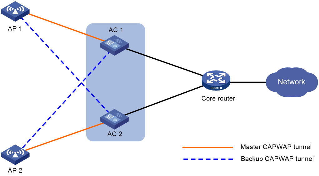
With dual-link backup enabled, an AP establishes a master CAPWAP tunnel and a backup CAPWAP tunnel with the master AC and the backup AC, respectively. The master and backup ACs cannot detect each other's link state in real time. When the backup AC takes over traffic forwarding upon a master AC failure, temporary communication interruption occurs. When the failed master AC recovers, the master CAPWAP tunnel preemption feature determines the master CAPWAP tunnel based on the AP connection priority.
Dual-link backup is applicable to networks that are service continuity insensitive.
Figure 1 Network diagram for dual-link backup
Restrictions and guidelines: Dual-link backup configuration
For the dual-link backup feature to function correctly, configure auto AP or manual APs on the two ACs. The manual AP configuration must be identical on both ACs. For more information, see "Managing APs."
You can configure APs by using the following methods:
· Configure APs one by one in AP view.
· Assign APs to an AP group and configure the AP group in AP group view.
· Configure all APs in global configuration view.
For an AP, the settings made in these views for the same parameter take effect in descending order of AP view, AP group view, and global configuration view.
Dual-link backup tasks at a glance
To configure dual-link backup, perform the following tasks:
1. Setting AP connection priority and specifying a backup AC
2. (Optional.) Configuring master CAPWAP tunnel preemption
3. (Optional.) Enabling client persistence
4. (Optional.) Configuring configuration synchronization between ACs in a dual-link backup system
Setting AP connection priority and specifying a backup AC
About this task
Set a higher AP connection priority for the master AC to ensure that APs can associate with the master AC first.
After an AP establishes a CAPWAP tunnel with the master AC, the AP will establish a backup CAPWAP tunnel with the specified backup AC.
Procedure
1. Enter system view.
system-view
2. Enter AP view or AP group view.
¡ Enter AP view.
wlan ap ap-name
¡ Enter AP group view.
wlan ap-group group-name
3. Set the AP connection priority.
priority priority
By default:
¡ In AP view, an AP uses the configuration in AP group view.
¡ In AP group view, the AP connection priority is 4.
4. Specify a backup AC.
backup-ac { ip ipv4-address | ipv6 ipv6-address }
By default:
¡ In AP view, an AP uses the configuration in AP group view.
¡ In AP group view, no backup AC is specified.
Configuring master CAPWAP tunnel preemption
About this task
This feature enables a backup CAPWAP tunnel to become a master tunnel after a 10-minute delay if the backup AC has higher AP connection priority than the master AC.
Procedure
1. Enter system view.
system-view
2. Enter AP view, AP group view, or global configuration view.
¡ Enter AP view.
wlan ap ap-name
¡ Enter AP group view.
wlan ap-group group-name
¡ Enter global configuration view.
wlan global-configuration
3. Configure master CAPWAP tunnel preemption.
wlan tunnel-preempt { disable | enable }
By default:
¡ In AP view, an AP uses the configuration in AP group view. If no configuration exists in AP group view, the AP uses the configuration in global configuration view.
¡ In AP group view, an AP uses the configuration in global configuration view.
¡ In global configuration view, master CAPWAP tunnel preemption is disabled.
Enabling client persistence
About this task
In a dual-link network, when the backup AC becomes the master AC, it synchronizes all client entries with the master AC. During the synchronization, wireless clients will go offline simultaneously and it will take a long time for them to come online again. With this feature enabled, the backup AC synchronizes entries with the master AC slowly, allowing wireless clients to slowly go offline and come online, thereby keeping clients online. This function is supported only when the client data packet forwarding location is on the AP.
To use this feature together with portal authentication, configure MAC-based quick portal authentication for users to complete authentication without awareness.
During master/backup switchover, the backup AC uses temporary client data to ensure that clients do not disconnect. After the switchover, you must execute wlan persistent-client reconnect on the new master AC to log off clients in batches and delete their temporary data. After the clients come online again, the new master AC regenerates normal client data.
Procedure
1. Enter system view.
system-view
2. Enter global configuration view.
wlan global-configuration
3. Enable client persistence.
client-persistence enable
By default, client persistence is disabled.
4. (Optional.) Configure delayed client reconnection for client persistence.
wlan persistent-client reconnect delay delay-minutes period period-minutes
Configuring configuration synchronization between ACs in a dual-link backup system
Configuring synchronizing WLAN configuration between ACs in a dual-link backup system
About this task
As a best practice to ensure configuration consistency between the two ACs in a dual-link backup system, configure WLAN settings on the AC with the TM role and then use this function to synchronize the WLAN settings to the AC with the TC role.
WLAN settings includes settings in AP view, AP group view, global configuration view, radio view, an AP group's radio view, and service template view, as well as settings related to authentication.
The following conditions might occur if you enable this feature:
· When the two ACs have the same WLAN settings, WLAN configuration synchronization is not performed.
· When the two ACs have different WLAN settings, the system generates a diff file named wlan_cfgsync.diff on the AC with the TM role and then automatically performs configuration synchronization. To view the WLAN configuration differences between the two ACs, use the more command.
Restrictions and guidelines
To use this feature, first set up a SmartMC network. This feature is supported only on the AC with the TM role.
Procedures
1. Enter system view.
system-view
2. Configure synchronizing WLAN configuration between ACs in a dual-link backup system.
wlan sync-configuration { from | to } peer-ac mac-address
Triggering consistency check on the WLAN configuration between the two ACs in a dual-link backup system
About this task
Perform this task to verify if the WLAN settings on the two ACs in a dual-link backup system are consistent. If an inconsistency is found, the AC with the TM role generates a diff file named wlan_cfgsync.diff. You can use the more command to view the diff file and determine whether to perform WLAN configuration synchronization and the synchronization direction.
Restrictions and guidelines
To use this feature, first set up a SmartMC network. This feature is supported only on the AC with the TM role.
Procedures
1. Enter system view.
system-view
2. Trigger consistency check on the WLAN configuration between the two ACs in a dual-link backup system.
wlan sync-configuration check peer-ac mac-address
Display and maintenance commands for dual-link backup
Execute display commands in any view and the reset command in user view.
|
Task |
Command |
|
Display information about clients kept online by client persistence. |
display wlan persistent-client |
|
Display the history of configuration synchronization between ACs in a dual-link backup scenario. |
display wlan sync-configuration history |
|
Clear clients kept online by client persistence. |
reset wlan persistent-client |
|
Clear the history of configuration synchronization between ACs in a dual-link backup scenario. |
reset wlan sync-configuration history |
Dual-link backup configuration examples
Example: Configuring dual-link backup
Network configuration
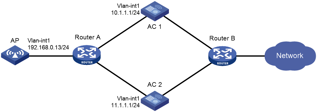
As shown in Figure 2, configure AC 1 to act as the master AC and AC 2 as the backup AC. When AC 1 fails and AC 2 takes over, the AP can communicate through AC 2. Configure the master CAPWAP tunnel preemption feature on the two ACs so that the AP reconnects to AC 1 when AC 1 recovers.
Procedure
1. Configure AC 1:
# Create VLAN-interface 1 and assign an IP address to it.
<AC1> system-view
[AC1] interface vlan-interface 1
[AC1-Vlan-interface1] ip address 10.1.1.1 24
[AC1-Vlan-interface1] quit
# Create an AP named ap1, and specify the AP model and serial ID. Set the AP connection priority to 7.
[AC1] wlan ap ap1 model WA6320
[AC1-wlan-ap-ap1] serial-id 219801A28N819CE0002T
[AC1-wlan-ap-ap1] priority 7
[AC1-wlan-ap-ap1] backup-ac ip 11.1.1.1
# Enable master CAPWAP tunnel preemption.
[AC1-wlan-ap-ap1] wlan tunnel-preempt enable
[AC1-wlan-ap-ap1] quit
2. Configure AC 2:
# Create VLAN-interface 1 and assign an IP address to it.
<AC2> system-view
[AC2] interface Vlan-interface 1
[AC2-Vlan-interface1] ip address 11.1.1.1 24
[AC2-Vlan-interface1] quit
# Create an AP named ap1, and specify the AP model and serial ID. Set the AP connection priority to 5.
[AC2] wlan ap ap1 model WA6320
[AC2-wlan-ap-ap1] serial-id 219801A28N819CE0002T
[AC2-wlan-ap-ap1] priority 5
# Specify a backup AC.
[AC2-wlan-ap-ap1] backup-ac ip 10.1.1.1
# Enable master CAPWAP tunnel preemption.
[AC2-wlan-ap-ap1] wlan tunnel-preempt enable
[AC2-wlan-ap-ap1] quit
Verifying the configuration
# Get the AP online on AC 1. (Details not shown.)
# Shut down VLAN-interface 1 on AC 1 and wait no longer than 3 minutes, during which service interruption occurs. (Details not shown.)
# Verify that the AP comes online on AC 2 and the AP state is R/M on AC 2. (Details not shown.)
# Bring up VLAN-interface 1 on AC 1. (Details not shown.)
# Verify that the AP comes online on AC 1 again and the AP state is R/M on AC 1 and R/B in AC 2. (Details not shown.)
Configuring WLAN uplink detection
About WLAN uplink detection
When the uplink of an AC fails, clients cannot access external networks through the APs that are connected to the AC. WLAN uplink detection associates the uplink state of an AC with the radio state of the connected APs. When the uplink fails, the AC disables the radios of the APs. When the uplink recovers, the AC enables the radios of the APs. The association ensures that clients can associate with APs connected to another AC when the uplink of an AC fails.
This feature collaborates with a detection module and the Track module to function.
· When the track entry is in Positive state, the AC enables the radios of the connected APs.
· When the track entry is in Negative state, the AC disables the radios of the connected APs.
· When the track entry is in Invalid state, the AC does not change the radio state of the connected APs.
For more information about the track module, see High Availability Configuration Guide.
Restrictions and guidelines: WLAN uplink detection
For the WLAN uplink detection feature to function correctly, configure a detection module to detect the uplink state, and associate a track entry with the detection module. For more information, see track configuration in High Availability Configuration Guide.
Configuring WLAN uplink detection
1. Enter system view.
system-view
2. Associate a track entry with the WLAN uplink detection feature.
wlan uplink track track-entry-number
By default, WLAN uplink detection is not associated with any track entry.
WLAN uplink detection configuration examples
Example: Configuring WLAN uplink detection
Network configuration
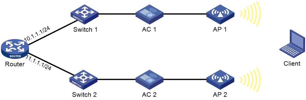
As shown in Figure 3, use an NQA operation to test the reachability of each AC's uplink. Configure WLAN uplink detection on each AC so that clients can associate with the AP connected to another AC when the uplink of an AC fails.
Procedure
1. Configure AC 1:
# Create an ICMP echo operation.
<AC1> system-view
[AC1] nqa entry admin test
[AC1-nqa-admin-test] type icmp-echo
# Specify 10.1.1.1 as the destination IP address of ICMP echo requests.
[AC1-nqa-admin-test-icmp-echo] destination ip 10.1.1.1
# Create reaction entry 1. If the number of consecutive probe failures reaches 5, collaboration is triggered.
[AC1-nqa-admin-test-icmp-echo] reaction 1 checked-element probe-fail threshold-type consecutive 5 action-type trigger-only
[AC1-nqa-admin-test-icmp-echo] quit
# Start the ICMP echo operation.
[AC1] nqa schedule admin test start-time now lifetime forever
# Configure track entry 1, and associate it with reaction entry 1 of the NQA operation (with administrator admin and operation tag test).
[AC1] track 1 nqa entry admin test reaction 1
# Associate track entry 1 with WLAN uplink detection.
[AC1] wlan uplink track 1
[AC1] quit
2. Configure AC 2:
# Create an ICMP echo operation.
<AC2> system-view
[AC2] nqa entry admin test
[AC2-nqa-admin-test] type icmp-echo
# Specify 11.1.1.1 as the destination IP address of ICMP echo requests.
[AC2-nqa-admin-test-icmp-echo] destination ip 11.1.1.1
# Create reaction entry 1. If the number of consecutive probe failures reaches 5, collaboration is triggered.
[AC2-nqa-admin-test-icmp-echo] reaction 1 checked-element probe-fail threshold-type consecutive 5 action-type trigger-only
[AC2-nqa-admin-test-icmp-echo] quit
# Start the ICMP echo operation.
[AC2] nqa schedule admin test start-time now lifetime forever
# Configure track entry 1, and associate it with reaction entry 1 of the NQA operation (with administrator admin and operation tag test).
[AC2] track 1 nqa entry admin test reaction 1
# Associate track entry 1 with WLAN uplink detection.
[AC2] wlan uplink track 1
[AC2] quit
Verifying the configuration
This example uses AC 1 to verify the configuration.
1. Verify that the radio state of AP 1 is Up when the state of track entry 1 is Positive:
# Display information about track entry 1.
<AC1> display track 1
Track ID: 1
State: Positive
Duration: 0 days 1 hours 5 minutes 48 seconds
Notification delay: Positive 0, Negative 0 (in seconds)
Tracked object:
NQA entry: admin test
Reaction: 1
# Display detailed information about AP ap1.
<AC1> display wlan ap name ap1 verbose
AP name : ap1
AP ID : 1
AP group name : default-group
State : Run
Backup type : Idle
Online time : 0 days 3 hours 25 minutes 12 seconds
System up time : 0 days 2 hours 22 minutes 12 seconds
Model : WA6320
Region code : CN
Region code lock : Disabled
Serial ID : 219801A28N819CE0002T
MAC address : 83D5-AB43-67FF
IP address : 1.1.1.2
UDP control port number : N/A
UDP data port number : N/A
H/W version : Ver.C
S/W version : V700R001B62D001
Boot version : 1.01
USB state : N/A
Power level : N/A
Power info : N/A
Description : wtp1
Priority : 4
Echo interval : 10 seconds
Echo count : 3 counts
Keepalive interval : 10 seconds
Discovery-response wait-time : 2 seconds
Statistics report interval : 50 seconds
Fragment size (data) : 1500
Fragment size (control) : 1450
MAC type : Local MAC & Split MAC
Tunnel mode : Local Bridging & 802.3 Frame & Native Frame
CAPWAP data-tunnel status : Up
Discovery type : DHCP
Retransmission count : 3
Retransmission interval : 5 seconds
Firmware upgrade : Enabled
Sent control packets : 1
Received control packets : 1
Echo requests : 0
Lost echo responses : 0
Average echo delay : 0
Last reboot reason : N/A
Latest IP address : N/A
Current AC IP : N/A
Tunnel down reason : N/A
Connection count : 1
Backup Ipv4 : Not configured
Backup Ipv6 : Not configured
Ctrl-tunnel encryption : Disabled
Ctrl-tunnel encryption state : Not encrypted
Data-tunnel encryption : Disabled
Data-tunnel encryption state : Not encrypted
LED mode : Normal
Remote configuration : Disabled
EnergySaving Level : 0
Radio 1:
Basic BSSID : N/A
Admin state : Up
Radio type : 802.11ax
Antenna type : internal
Client dot11ac-only : Disabled
Client dot11n-only : Disabled
Channel band-width : 20/40/80MHz
Operating bandwidth : 20/40/80MHz
Secondary channel offset : SCA
Short GI for 20MHz : Supported
Short GI for 40MHz : Supported
Short GI for 80MHz : Supported
Short GI for 160MHz : Not supported
mimo : Not Config
Green-Energy-Management : Disabled
A-MSDU : Enabled
A-MPDU : Enabled
LDPC : Not Supported
STBC : Supported
Operational VHT-MCS Set:
Mandatory : Not configured
Supported : NSS1 0,1,2,3,4,5,6,7,8,9
NSS2 0,1,2,3,4,5,6,7,8,9
Multicast : Not configured
Operational HT MCS Set:
Mandatory : Not configured
Supported : 0, 1, 2, 3, 4, 5, 6, 7, 8, 9,
10, 11, 12, 13, 14, 15
Multicast : Not configured
Channel : 52(auto)
Max power : 20 dBm
Operational rate:
Mandatory : 6, 12, 24 Mbps
Supported : 9, 18, 36, 48, 54 Mbps
Multicast : 24 Mbps
Disabled : Not configured
Distance : 1 km
ANI : Enabled
Fragmentation threshold : 2346 bytes
Beacon interval : 100 TU
Protection threshold : 2346 bytes
Long retry threshold : 4
Short retry threshold : 7
Maximum rx duration : 2000 ms
Noise Floor : 0 dBm
Protection mode : cts-to-self
MU-TxBF : Enabled
SU-TxBF : Enabled
Continuous mode : N/A
Client dot11ax-only : Disabled
Operational HE-MCS Set:
Mandatory : Not configured
Supported : NSS1 0,1,2,3,4,5,6,7,8,9,10,11
NSS2 0,1,2,3,4,5,6,7,8,9,10,11
Multicast : Not configured
OFDMA random access RUs : Not Supported
Channel Width Set : 0x02
DL-OFDMA : Enabled
UL-OFDMA : Enabled
UL-MU-MIMO : Disabled
BSS-COLOR : Enabled
TWT negotiation : Disabled
HT protection mode : No protection
Radio 2:
Basic BSSID : N/A
Admin state : Up
Radio type : 802.11gax
Antenna type : internal
Client dot11ac-only : Disabled
Client dot11n-only : Disabled
Channel bandwidth : 20MHz
Operating bandwidth : 20MHz
Secondary channel offset : SCN
Short GI for 20MHz : Supported
Short GI for 40MHz : Supported
Short GI for 80MHz : Not supported
Short GI for 160MHz : Not supported
mimo : Not Config
Green-Energy-Management : Disabled
A-MSDU : Enabled
A-MPDU : Enabled
LDPC : Supported
STBC : Supported
Operational VHT-MCS Set:
Mandatory : Not configured
Supported : Not configured
Multicast : Not configured
Operational HT MCS Set:
Mandatory : Not configured
Supported : 0, 1, 2, 3, 4, 5, 6, 7, 8, 9,
10, 11, 12, 13, 14, 15
Multicast : Not configured
Channel : 11(auto)
Channel usage(%) : 0
Max power : 20 dBm
Operational rate:
Mandatory : 1, 2, 5.5, 11 Mbps
Multicast : Auto
Supported : 6, 9, 12, 18, 24, 36, 48, 54 Mbps
Disabled : Not configured
Distance : 1 km
ANI : Enabled
Fragmentation threshold : 2346 bytes
Beacon interval : 100 TU
Protection threshold : 2346 bytes
Long retry threshold : 4
Short retry threshold : 7
Maximum rx duration : 2000 ms
Noise floor : 0 dBm
Protection mode : cts-to-self
SU-TxBF : Enabled
Continuous mode : N/A
Client dot11ax-only : Disabled
Operational HE-MCS Set:
Mandatory : Not configured
Supported : NSS1 0,1,2,3,4,5,6,7,8,9,10,11
NSS2 0,1,2,3,4,5,6,7,8,9,10,11
Multicast : Not configured
OFDMA random access RUs : Not Supported
Channel Width Set : 0x01
DL-OFDMA : Enabled
UL-OFDMA : Enabled
UL-MU-MIMO : Disabled
BSS-COLOR : Enabled
TWT negotiation : Disabled
HT protection mode : No protection
2. Verify that the radio state of AP 1 is Down when the state of track entry 1 is Negative:
# Display information about track entry 1.
<AC1> display track 1
Track ID: 1
State: Negative
Duration: 0 days 2 hours 5 minutes 48 seconds
Notification delay: Positive 0, Negative 0 (in seconds)
Tracked object:
NQA entry: admin test
Reaction: 1
# Display detailed information about AP ap1.
<AC1> display wlan ap name ap1 verbose
AP name : ap1
AP ID : 1
AP group name : default-group
State : Run
Backup type : Idle
Online time : 0 days 3 hours 25 minutes 12 seconds
System up time : 0 days 2 hours 22 minutes 12 seconds
Model : WA6320
Region code : CN
Region code lock : Disabled
Serial ID : 219801A28N819CE0002T
MAC address : 83D5-AB43-67FF
IP address : 1.1.1.2
UDP control port number : N/A
UDP data port number : N/A
H/W version : Ver.C
S/W version : V700R001B62D001
Boot version : 1.01
USB state : N/A
Power level : N/A
Power info : N/A
Description : wtp1
Priority : 4
Echo interval : 10 seconds
Echo count : 3 counts
Keepalive interval : 10 seconds
Discovery-response wait-time : 2 seconds
Statistics report interval : 50 seconds
Fragment size (data) : 1500
Fragment size (control) : 1450
MAC type : Local MAC & Split MAC
Tunnel mode : Local Bridging & 802.3 Frame & Native Frame
CAPWAP data-tunnel status : Up
Discovery type : DHCP
Retransmission count : 3
Retransmission interval : 5 seconds
Firmware upgrade : Enabled
Sent control packets : 1
Received control packets : 1
Echo requests : 0
Lost echo responses : 0
Average echo delay : 0
Last reboot reason : N/A
Latest IP address : N/A
Current AC IP : N/A
Tunnel down reason : N/A
Connection count : 1
Backup Ipv4 : Not configured
Backup Ipv6 : Not configured
Ctrl-tunnel encryption : Disabled
Ctrl-tunnel encryption state : Not encrypted
Data-tunnel encryption : Disabled
Data-tunnel encryption state : Not encrypted
LED mode : Normal
Remote configuration : Disabled
EnergySaving Level : 0
Radio 1:
Basic BSSID : N/A
Admin state : Down
Radio type : 802.11ax
Antenna type : internal
Client dot11ac-only : Disabled
Client dot11n-only : Disabled
Channel band-width : 20/40/80MHz
Operating bandwidth : 20/40/80MHz
Secondary channel offset : SCA
Short GI for 20MHz : Supported
Short GI for 40MHz : Supported
Short GI for 80MHz : Supported
Short GI for 160MHz : Not supported
mimo : Not Config
Green-Energy-Management : Disabled
A-MSDU : Enabled
A-MPDU : Enabled
LDPC : Not Supported
STBC : Supported
Operational VHT-MCS Set:
Mandatory : Not configured
Supported : NSS1 0,1,2,3,4,5,6,7,8,9
NSS2 0,1,2,3,4,5,6,7,8,9
Multicast : Not configured
Operational HT MCS Set:
Mandatory : Not configured
Supported : 0, 1, 2, 3, 4, 5, 6, 7, 8, 9,
10, 11, 12, 13, 14, 15
Multicast : Not configured
Channel : 52(auto)
Max power : 20 dBm
Operational rate:
Mandatory : 6, 12, 24 Mbps
Supported : 9, 18, 36, 48, 54 Mbps
Multicast : 24 Mbps
Disabled : Not configured
Distance : 1 km
ANI : Enabled
Fragmentation threshold : 2346 bytes
Beacon interval : 100 TU
Protection threshold : 2346 bytes
Long retry threshold : 4
Short retry threshold : 7
Maximum rx duration : 2000 ms
Noise Floor : 0 dBm
Protection mode : cts-to-self
MU-TxBF : Enabled
SU-TxBF : Enabled
Continuous mode : N/A
Client dot11ax-only : Disabled
Operational HE-MCS Set:
Mandatory : Not configured
Supported : NSS1 0,1,2,3,4,5,6,7,8,9,10,11
NSS2 0,1,2,3,4,5,6,7,8,9,10,11
Multicast : Not configured
OFDMA random access RUs : Not Supported
Channel Width Set : 0x02
DL-OFDMA : Enabled
UL-OFDMA : Enabled
UL-MU-MIMO : Disabled
BSS-COLOR : Enabled
TWT negotiation : Disabled
HT protection mode : No protection
Radio 2:
Basic BSSID : N/A
Admin state : Down
Radio type : 802.11gax
Antenna type : internal
Client dot11ac-only : Disabled
Client dot11n-only : Disabled
Channel bandwidth : 20MHz
Operating bandwidth : 20MHz
Secondary channel offset : SCN
Short GI for 20MHz : Supported
Short GI for 40MHz : Supported
Short GI for 80MHz : Not supported
Short GI for 160MHz : Not supported
mimo : Not Config
Green-Energy-Management : Disabled
A-MSDU : Enabled
A-MPDU : Enabled
LDPC : Supported
STBC : Supported
Operational VHT-MCS Set:
Mandatory : Not configured
Supported : Not configured
Multicast : Not configured
Operational HT MCS Set:
Mandatory : Not configured
Supported : 0, 1, 2, 3, 4, 5, 6, 7, 8, 9,
10, 11, 12, 13, 14, 15
Multicast : Not configured
Channel : 11(auto)
Channel usage(%) : 0
Max power : 20 dBm
Operational rate:
Mandatory : 1, 2, 5.5, 11 Mbps
Multicast : Auto
Supported : 6, 9, 12, 18, 24, 36, 48, 54 Mbps
Disabled : Not configured
Distance : 1 km
ANI : Enabled
Fragmentation threshold : 2346 bytes
Beacon interval : 100 TU
Protection threshold : 2346 bytes
Long retry threshold : 4
Short retry threshold : 7
Maximum rx duration : 2000 ms
Noise floor : 0 dBm
Protection mode : cts-to-self
SU-TxBF : Enabled
Continuous mode : N/A
Client dot11ax-only : Disabled
Operational HE-MCS Set:
Mandatory : Not configured
Supported : NSS1 0,1,2,3,4,5,6,7,8,9,10,11
NSS2 0,1,2,3,4,5,6,7,8,9,10,11
Multicast : Not configured
OFDMA random access RUs : Not Supported
Channel Width Set : 0x01
DL-OFDMA : Enabled
UL-OFDMA : Enabled
UL-MU-MIMO : Disabled
BSS-COLOR : Enabled
TWT negotiation : Disabled
HT protection mode : No protection
