- Table of Contents
- Related Documents
-
| Title | Size | Download |
|---|---|---|
| 01-Text | 6.20 MB |
Set up the configuration environment
Connect the UniSystem server to the network
Obtain the IP address of the UniSystem server
About network template management
Update the firmware by using HDM out-of-band management
About firmware update by using HDM out-of-band management
Configure WeCom, SMS and voice notification
About WeCom, SMS and voice notification
About software push and installation
This document only provides guidance for configuring UniSystem. To obtain all the features and detailed information, see H3C Servers UniSystem User Guide.
Overview
About UniSystem
UniSystem is an intelligent, extensible server management software that allows you to manage servers remotely from a unified, intuitive graphical user interface. It effectively helps enterprises enhance their data center-level O&M capabilities. Enterprises can flexibly monitor and configure devices in data centers through UniSystem as needed to create a customized O&M environment. UniSystem can effectively help enterprises improve operational efficiency and reduce maintenance costs.
UniSystem provides the following benefits:
· Cross-platform support—UniSystem can be deployed by importing VM files, making the software lightweight and easy to install. This simplifies deployment for maintenance staff.
· Bulk server deployment—UniSystem supports bulk deployment of servers. This greatly improves the deployment efficiency before the servers come online. A single UniSystem node can manage up to 5000 servers and 30 switches simultaneously.
· Support for template-based configuration—UniSystem supports server templates. This can separate server configurations from hardware, offering stateless computing capabilities.
· Open integration capabilities—UniSystem provides RESTful interfaces based on HTTPS/HTTP to allow third parties to integrate UniSystem management system into the customer service process.
UniSystem architecture
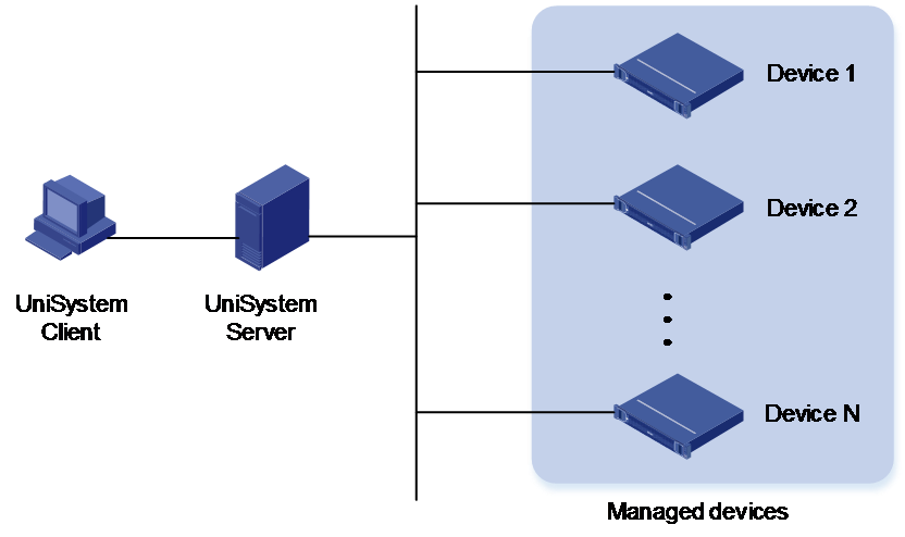
As shown in Figure 1, the UniSystem architecture contains the following elements:
· UniSystem client—An endpoint device (such as a PC) used to access UniSystem through the Web browser.
· UniSystem server—A PC, physical server, or AE module hosting the UniSystem server software. The AE module ships with UniSystem pre-installed.
· Managed devices—Devices managed by UniSystem.
The UniSystem client and UniSystem server can reside on the same device.
Figure 1 UniSystem architecture
Application scenarios
UniSystem can run in PCs or servers. As a bulk server management tool, UniSystem helps enterprises manage, monitor, update, and query resources more effectively to simplify device management.
The H3C UniServer B16000 AE module comes with UniSystem pre-installed. UniSystem embedded within an AE module can manage not only local enclosures, but also blade servers, rack servers, and switches in the enclosures. UniSystem in an AE module supports hybrid IT architecture and cluster-mode management.
Use this document
This document describes the configuration
process and related concepts of the common functions provided by UniSystem. For
information about the configuration methods, parameters, and restrictions and
guidelines not mentioned in this document, see the UniSystem online help. To
quickly access the online help, click ![]() next to
the page title on the Web interface of UniSystem. For more information about
configuration examples, see H3C Servers UniSystem
Configuration Examples.
next to
the page title on the Web interface of UniSystem. For more information about
configuration examples, see H3C Servers UniSystem
Configuration Examples.
This document provides general product information. The information in this document might differ from your product if it contains custom configuration options or features.
The model name of a hardware option in this document might differ slightly from its model name label. A model name label might add a prefix or suffix to the hardware-coded model name for purposes such as identifying the matching server brand or applicable region. For example, storage controller model HBA-1000-M2-1 represents storage controller model label UN-HBA-1000-M2-1, which has a prefix of UN-.
The webpage screenshots used in this document are for illustration only and might differ from your products.
Applicable products
· H3C UniServer R4930 G7
· H3C UniServer R4970 G7
· H3C UniServer R5330 G7
· H3C UniServer R5500 G7
· H3C UniServer B16000
· H3C UniServer R3950 G6
· H3C UniServer R4300 G6
· H3C UniServer R4500 G6
· H3C UniServer R4700 G6
· H3C UniServer R4700LE G6
· H3C UniServer R4900 G6
· H3C UniServer R4900LE G6 Ultra
· H3C UniServer R4900 G6 Ultra
· H3C UniServer R4950 G6
· H3C UniServer R5350 G6
· H3C UniServer R5300 G6
· H3C UniServer R5500 G6 AMD
· H3C UniServer R5500 G6 Intel
· H3C UniServer R6700 G6
· H3C UniServer R6900 G6
· H3C UniServer B5700 G5
· H3C UniServer R4300 G5
· H3C UniServer R4330 G5
· H3C UniServer R4330 G5 H3
· H3C UniServer R4700 G5
· H3C UniServer R4900 G5
· H3C UniServer R4930 G5
· H3C UniServer R4930 G5 H3
· H3C UniServer R4930 G5 H3 PKG
· H3C UniServer R4930LC G5 H3
· H3C UniServer R4950 G5
· H3C UniServer R5300 G5
· H3C UniServer R5500 G5
· H3C UniServer R5500LC G5
· H3C UniServer R6900 G5
· H3C UniServer B5700 G3
· H3C UniServer B5800 G3
· H3C UniServer B7800 G3
· H3C UniServer E3200 G3
· H3C UniServer R2700 G3
· H3C UniServer R2900 G3
· H3C UniServer R4300 G3
· H3C UniServer R4360 G3
· H3C UniServer R4500 G3
· H3C UniServer R4700 G3
· H3C UniServer R4900 G3
· H3C UniServer R4950 G3
· H3C UniServer R4960 G3
· H3C UniServer R5300 G3
· H3C UniServer R6700 G3
· H3C UniServer R6900 G3
· H3C UniServer R8900 G3
Log in to UniSystem
Set up the configuration environment
Connect the UniSystem server to the network
To log in to UniSystem running on a PC or a server, make sure the UniSystem client and UniSystem server reside on the same network segment.
Before you log in to UniSystem running on an AE module, perform the following tasks:
1. Make sure the enclosure has a minimum of one AE module present. An enclosure supports a maximum of two AE modules, as shown in Figure 2.
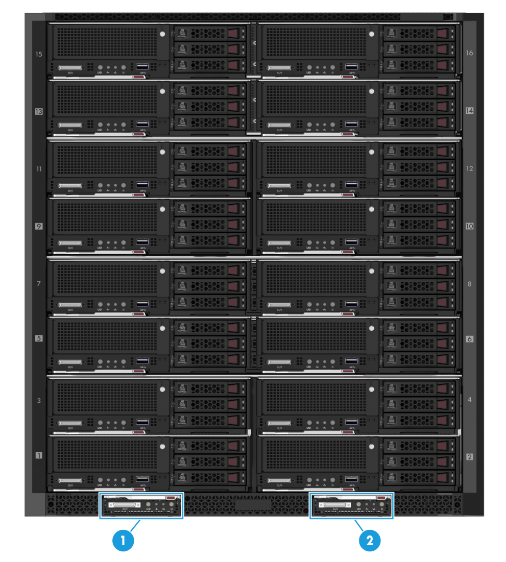
|
(1) Slot E1 |
(2) Slot E2 |
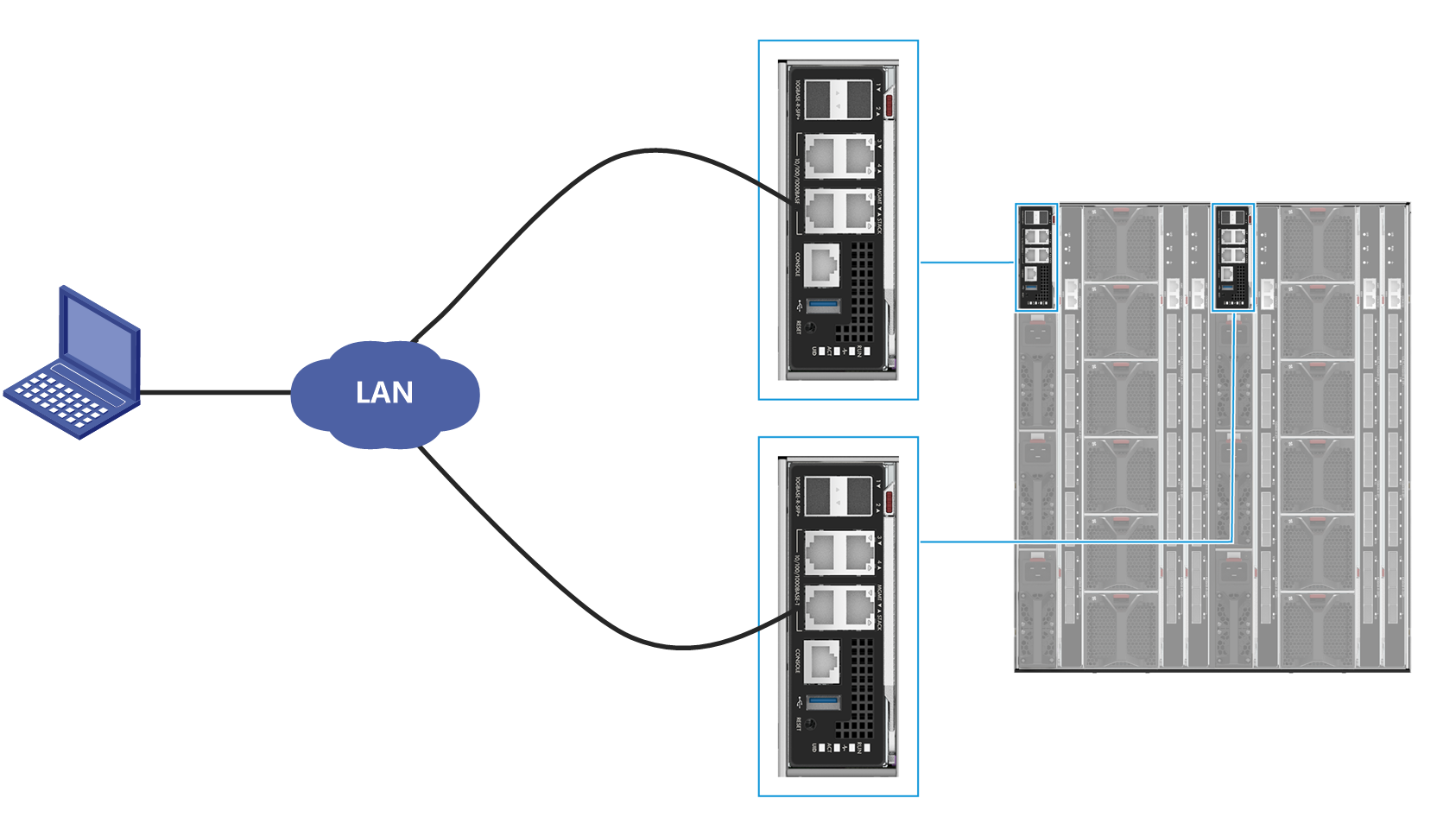
2. Connect the Ethernet port on the UniSystem client host to the MGMT port on the primary or standby OM module over the LAN, as shown in Figure 3.
Figure 3 Connect the OM module
3. Configure the IP address of the UniSystem client to be on the same network segment as the UniSystem server. The default IP address of UniSystem is as shown in Table 1.
Obtain the IP address of the UniSystem server
|
|
CAUTION: After you log in to UniSystem running in an AE module by using the default IP address, change the UniSystem IP address to avoid IP address conflicts in the future. |
Table 1 shows the default settings for UniSystem.
Table 1 Default UniSystem settings
|
Item |
UniSystem server location |
Value |
|
Username |
N/A |
admin |
|
Password |
Password@_ |
|
|
UniSystem login IP address |
AE module slot E1 |
192.168.0.100/24 |
|
AE module slot E2 |
192.168.0.101/24 |
|
|
Non-AE environment |
System IP address of the device where UniSystem resides. |
UniSystem client requirements
Users can access UniSystem from a Web browser directly. Table 2 shows the supported Web browsers and recommended resolution.
Table 2 Browser and resolution requirements
|
Browsers |
Resolution |
|
· Google Chrome 66.0 or later · Mozilla Firefox 60.0 or later · Internet Explorer 11 or later |
1600 × 900 or higher |
Log in to UniSystem
1. Enter either of the following URLs in the address bar of the browser:
¡ http://UniSystem ip address:port , where port represents the HTTP port number used by UniSystem.
¡ https://UniSystem ip address:port , where port represents the HTTPS port number used by UniSystem.
You can configure the HTTP port and HTTPS port for UniSystem in the UniSystem service startup settings. For more information, see H3C Servers UniSystem Installation Guide.
Alternatively, you can access UniSystem locally from the server where UniSystem is installed. To do so, enter http://localhost:port or http://127.0.0.1 in the address bar of the Web browser.
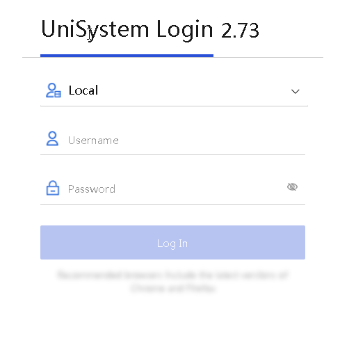
2. On the UniSystem login page, enter the username and password of a UniSystem user and click Log In.
3. Introduction to the Web interface of UniSystem
After you log in to UniSystem, the Dashboard page of the UniSystem Web interface opens, as shown in Figure 5.
On the Dashboard page, you can view the system information through dynamic widgets, including Device Summary, Server Alarms, Asset Statistics, Top 5 Servers by Temperature, Top 5 Servers by Power, Top 5 Servers by CPU/Memory Usage (for G6 servers).
You can use Shortcuts
to access a specified menu directly. To add a menu to Shortcuts,
click ![]() for that menu. To remove a menu from Shortcuts, click
for that menu. To remove a menu from Shortcuts, click ![]() for that
menu. You can add a maximum of 10 menu items to Shortcuts.
for that
menu. You can add a maximum of 10 menu items to Shortcuts.
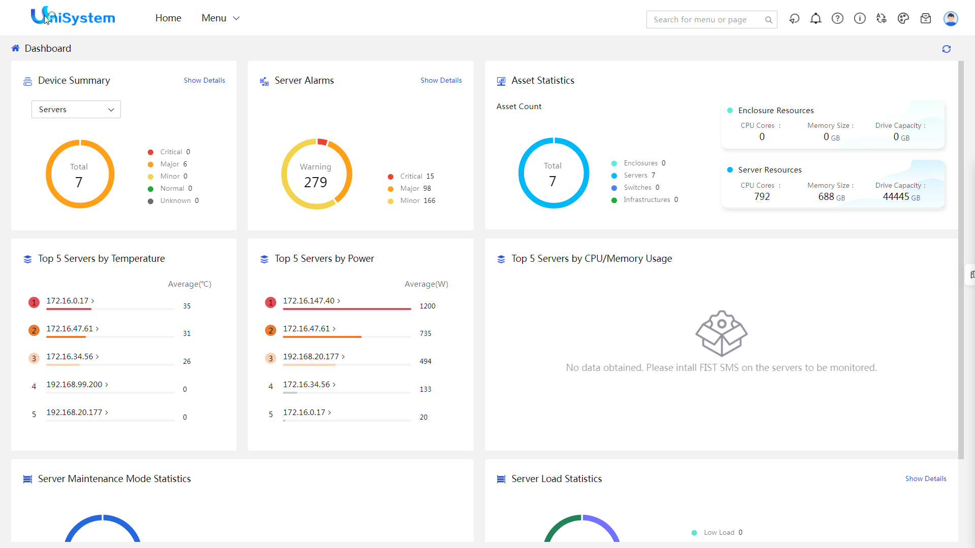
Table 3 UniSystem Web interface layout
|
Name |
Description |
|
Header section |
· · · · |
|
Work pane |
Displays operation information and function links. |
Manage user settings
Configure users
About this task
UniSystem supports login from both local users and LDAP users, and provides password authentication to ensure system security.
Application scenarios
· Local users: You add access users and assign a role to each user. UniSystem provides a default admin user account named admin with the admin role.
· LDAP user groups: Connect to the LDAP server and add a user group with the same permissions to unify the management and permission assignment for users.
Configuration workflow
Figure 6 shows the user configuration workflow and Table 4 shows the configuration tasks.
Figure 6 User configuration workflow
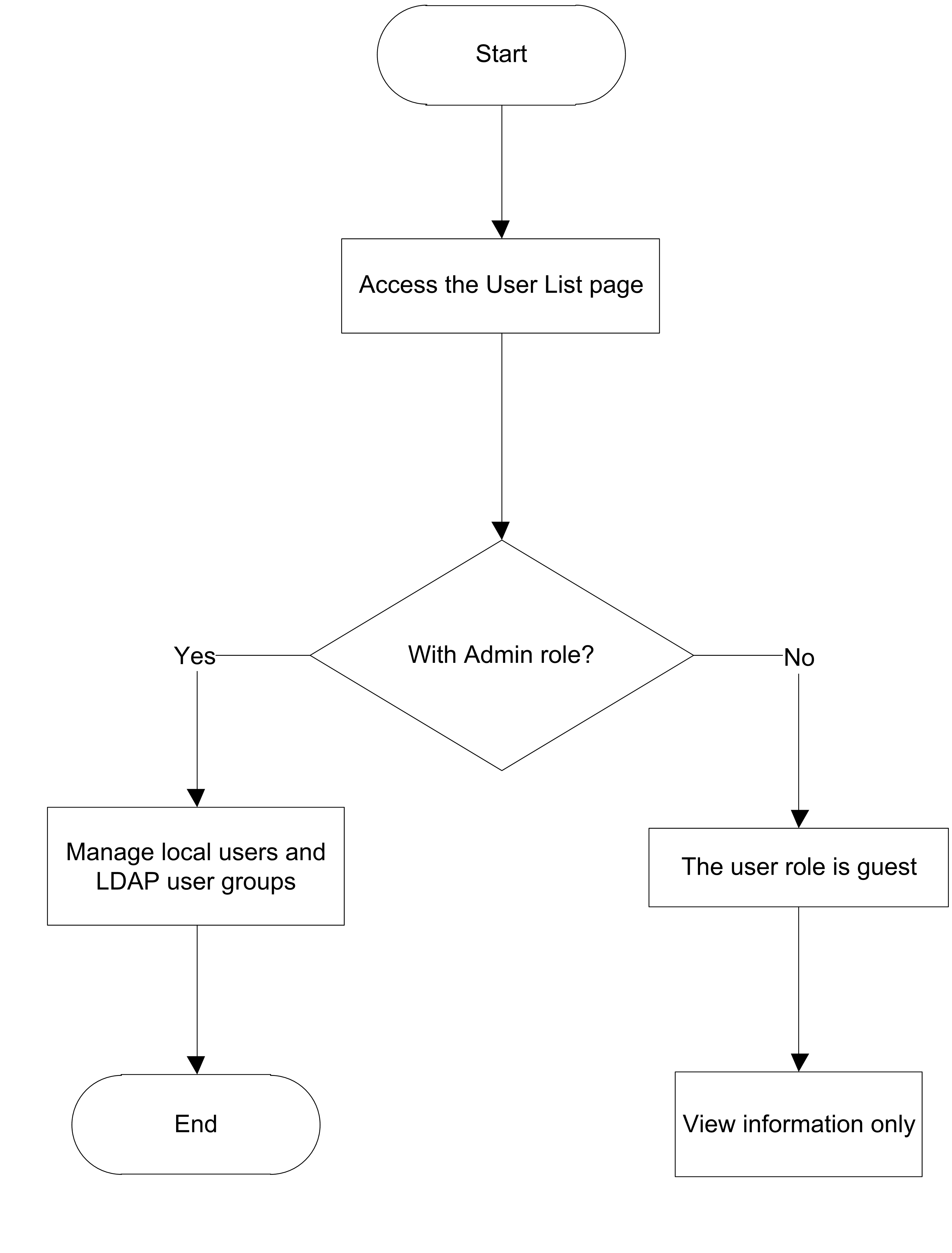
Table 4 Configuration task description
|
Task |
Description |
|
Manage local users |
Add, edit, and delete users, and set a password policy and login rules. |
|
Manage LDAP user groups |
Add, edit, and delete LDAP users. |
Restrictions and guidelines
· A user password must meet all the requirements in the password policy.
· Editing an online user will forcibly log out the user. The new settings take effect at the next login of that user.
Procedures
Manage local users
1. In the navigation pane, select Menu > System > User List.
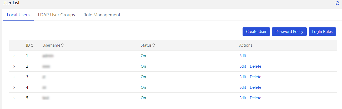
2. Add, edit, or delete users as required.
3. Configure a password policy.
Manage LDAP user groups
1. In the navigation pane, select Menu > System > User List.
2. Click the LDAP User Groups tab.
Figure 8 LDAP user group list
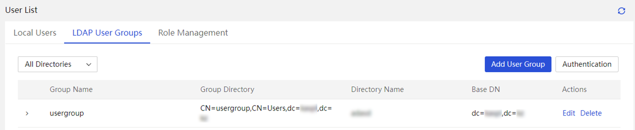
3. Add, edit, or delete LDAP users as required.
Manage devices
Manage enclosures
About enclosure management
You can manage enclosures and the blade servers and other modules in the enclosures.
Application scenarios
· You can view enclosure information, manage enclosures, and bulk install operating systems on blade servers through PXE.
· You can add an enclosure to UniSystem for managed by specifying the IP address, username, and password of the OM module. In addition, if UniSystem is running in an AE module, the enclosure where the AE module resides will be added to UniSystem automatically.
Configuration workflow
Figure 9 shows the configuration workflow for enclosure management. Table 5 shows the configuration tasks.
Figure 9 Enclosure management workflow

Table 5 Configuration task description
|
Task |
Description |
|
Add and remove enclosures |
Add enclosures to UniSystem or remove other enclosures from the enclosure list. |
|
Configure power caps for enclosures |
Set the power caps for the managed enclosures on UniSystem. |
|
Set the power mode for an enclosure |
You can configure the power redundancy mode for an enclosure according to the installed power supplies, total power consumption, and redundancy requirements on that enclosure. |
Prerequisites
Install blade servers to enclosures.
Restrictions and guidelines
· If UniSystem is running in an AE module, the enclosure where the AE module resides will be added to UniSystem automatically and cannot be deleted. If the enclosure where the AE module resides to be added has enclosures cascaded, UniSystem will automatically add the cascaded enclosures.
· The enclosures support only the PSR3000-12A power supply with rated power 3000 W.
Procedures
Add and remove enclosures
Prerequisites
Before you add an enclosure, verify that the OM management address of the enclosure to be added is on the same subnet with the UniSystem server (AE module). If the OM management address of the enclosure to be added is on a different subnet from UniSystem, you must configure the network settings to enable UniSystem to communicate with the enclosure.
Procedure
1. In the navigation pane, select Menu > Devices > Enclosure List.
2. Add or remove enclosures as needed.
Configure power caps for enclosures
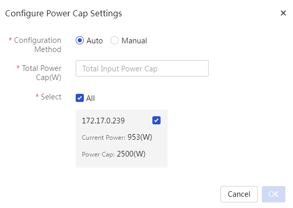
1. In the navigation pane select Menu > Devices > Enclosure List. Click Configure Power Caps.
2. Select a configuration method.
¡ If you select Auto, select the target enclosures and specify the total power cap value that can be allocated to the selected enclosures, as shown in Figure 10.
|
|
NOTE: · The power cap of an enclosure is in the range of 2500 W to 18000 W. · To dynamically set the power caps for N enclosures from a total available power cap value, specify the total power cap value in the range of 2500 W*N to 18000W*N. |
Figure 10 Configure UniSystem to dynamically allocate power caps to the selected enclosures
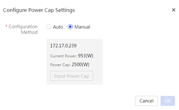
¡ If you select Manual, specify a power cap value for each enclosure, as shown in Figure 11.
Figure 11 Manually set the power caps for enclosures
3. Click OK.
Set the power mode for an enclosure
About this task
Perform this task to configure the power settings for an enclosure.
The power supply system of an enclosure can contain up to six hot-swappable power supplies. Install power supplies and configure the power redundancy mode according to the enclosure's power requirements, which vary depending on the number and type of devices installed in the enclosure.
UniSystem supports the following power management features:
· Power redundancy mode—Protects an enclosure from power supply failures.
UniSystem supports both the N+1 and N+N redundancy modes. In the event of one or more power supply failures, the redundant power supplies take over the load to prevent the system from powering off. The system powers off only when the surviving power supplies do not have enough power to meet the system's power requirements. If no redundant power supply is available (as is the case with the No Redundancy mode), the system might power off when one power supply fails.
· Dynamic power saving mode—Automatically places unused power supplies in standby mode to increase enclosure power supply efficiency, thereby minimizing enclosure power consumption during lower power demand. Increased power demands automatically return standby power supplies to full performance.
For example, assume that an enclosure has six power supplies installed, is configured to work in N+1 power redundancy mode, and requires two active power supplies to supply the current power.
¡ If the dynamic power saving mode is enabled, only three power supplies share in delivering the enclosure power load, with one being the redundant power supply. The remaining three power supplies will be placed in standby mode.
¡ If the dynamic power saving mode is disabled, all of the six power supplies share the power load.
Restrictions and guidelines
· Make sure all power supplies installed in the enclosure are of the same model.
Table 6 provides information about supported power supplies.
Supported power supplies
|
Type |
Model |
Rated input voltage range |
Maximum rated output power |
|
3000 W AC power supply |
PSR3000-12A |
100 VAC to 240 VAC |
3000 W |
· When setting the power redundancy mode for an enclosure, make sure the enclosure has the correct number of power supplies installed in the correct locations.
Table 7 shows the recommended power settings for an enclosure with 3000 W AC power supplies. If the number of power supplies exceeds the recommended number, enable the dynamic power saving mode to reduce power consumption.
Table 7 Recommended power settings for an enclosure with 3000 W AC power supplies
|
Max power that can be supplied |
Power redundancy mode |
Number of power supplies installed |
Recommended power supply bays |
|
3000 W |
No Redundancy |
1 |
PSU_1 |
|
6000 W |
No Redundancy |
2 |
PSU_1, PSU_2 |
|
9000 W |
No Redundancy |
3 |
PSU_1, PSU_2, PSU_3 |
|
12000 W |
No redundancy |
4 |
PSU_1, PSU_2, PSU_3, PSU_4 |
|
15000 W |
No redundancy |
5 |
PSU_1, PSU_2, PSU_3, PSU_4, PSU_5 |
|
18000 W |
No redundancy |
6 |
PSU_1, PSU_2, PSU_3, PSU_4, PSU_5, PSU_6 |
|
3000 W |
1+1 redundancy |
2 |
PSU_1, PSU_2 |
|
6000 W |
2+1 redundancy |
3 |
PSU_1, PSU_2, PSU_3 |
|
9000 W |
3+1 redundancy |
4 |
PSU_1, PSU_2, PSU_3, PSU_4 |
|
12000 W |
4+1 redundancy |
5 |
PSU_1, PSU_2, PSU_3, PSU_4, PSU_5 |
|
15000 W |
5+1 redundancy |
6 |
PSU_1, PSU_2, PSU_3, PSU_4, PSU_5, PSU_6 |
|
6000 W |
2+2 redundancy |
4 |
PSU_1, PSU_2, PSU_3, PSU_4 |
|
9000 W |
3+3 redundancy |
6 |
PSU_1, PSU_2, PSU_3, PSU_4, PSU_5, PSU_6 |
Manage servers
About server management
UniSystem can manage servers in bulk through HDM or FIST SMS.
Application scenarios
You can management one or multiple servers.
Configuration workflow
Figure 12 shows the configuration workflow for server management. Table 8 shows the configuration tasks.
Figure 12 Sever management workflow
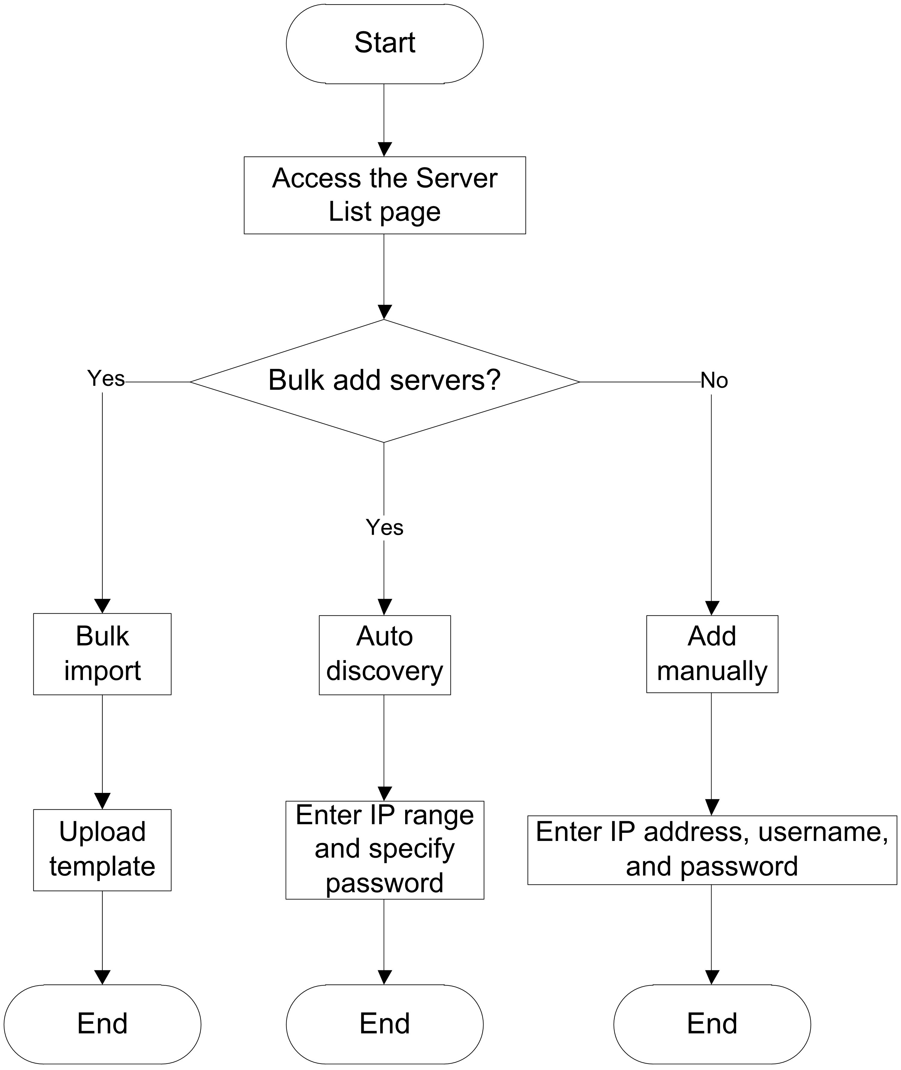
Table 8 Configuration task description
|
Task |
Description |
|
Import servers |
Import servers by using a template. |
|
Discover servers |
Automatically discover servers in bulk. |
|
Manually add a server |
You can add servers to UniSystem one by one. |
Restrictions and guidelines
· When you add a FIST SMS server node to UniSystem, make sure the following requirements are met:
¡ The firewall is disabled on the server or port 12580 is added to the whitelist in the firewall.
¡ SELinux is disabled.
¡ The server has HDM installed and HDM is not being updated.
· The FIST SMS server node can use the IP address of the operating system to connect to the UniSystem server. When you add an HDM server node to UniSystem, make sure UniSystem can connect to the HDM dedicated network port or shared network port on the HDM server node.
Procedures
Manually add a server
1. In the navigation pane, select Menu > Devices > Server List.
2. Click Add, select Add Manually.
3. Enter device information and select a label.
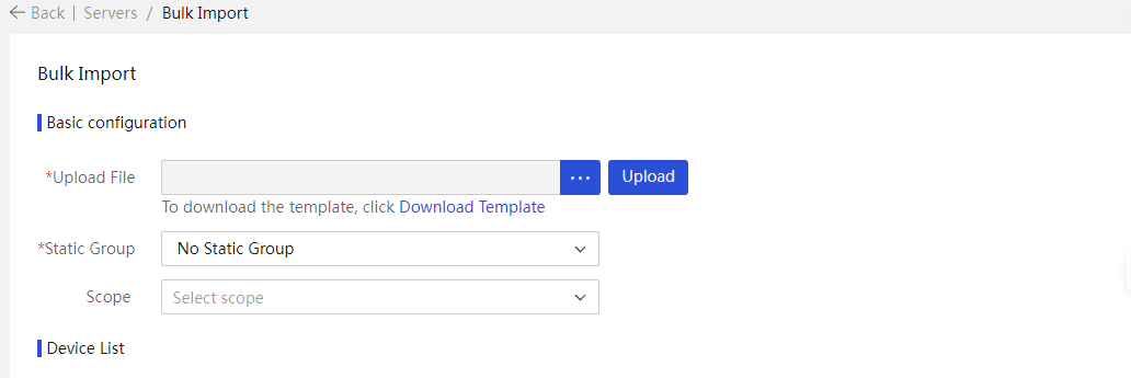
Import servers
1. In the navigation pane, select Menu > Devices > Server List.
2. Click Add, and then select Bulk Import.to access the Import Devices page.
3. Upload a template file to import devices. A template file can be in the TXT, XLSX, or XLS format. For more information about the template file, see Table 9.
Table 9 Template file description
|
Template |
Description |
|
template-1.txt |
Template in TXT format. Each row represents a device in the format of IP address, username, password, and port number (optional). For an HDM server node, specify the IP address, username, password, and port number (optional). For a FIST SMS server node, just specify the IP address. |
|
template-2.xlsx |
Template in XLSX format. Each row represents a device with the device type, IP address, username, password, and port number (optional) listed sequentially from column 1 to column 5. For an HDM server node, specify the device type, IP address, username, password, and port number (optional). For a FIST SMS server node, just specify the device type and IP address. |
|
template-3.xls |
· Template in XLS format. · Each row represents a device with the device type, IP address, username, password, and port number (optional) listed sequentially from column 1 to column 5. For an HDM server node, specify the device type, IP address, username, password, and port number (optional). · For a FIST SMS server node, just specify the device type and IP address. |
Discover servers
1. In the navigation pane, select Menu > Devices > Server List.
2. Click Add and select Auto Discovery.
3. Select the device type and the search method.
¡ if you select All or HDM as the device type, enter the start and end IP addresses of an IP address range and the username and password.
¡ if you select FIST SMS as the device type, enter the start and end IP addresses of an IP address range.
4. select whether to add the discovered servers automatically. If you select Yes for Auto Add After Searching, enter the number of search cycles.
5. Select a label.
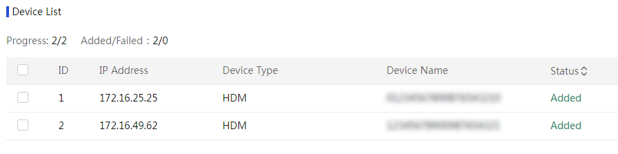
6. Click Search. UniSystem starts to search for servers.
¡ if the Add Manually method is used, UniSystem lists all the discovered servers on a list. You can select the servers to be added, and then click Add.
¡ if the Add Automatically method is used, UniSystem automatically add servers once they are discovered.
Configure IP settings in bulk
About this task
Perform this task to edit the HDM management IP addresses of servers in bulk by using IP configuration template files. The servers can be those managed by UniSystem or those not managed. This feature is available only for servers using HDM-3.10 or later.
UniSystem supports bulk setting of IP addresses in the following ways:
· IP Address—Applicable to scenarios where the server’s default HDM management IP address has been changed.
¡ Make sure the UniSystem management IP address and the server's current HDM management IP address are on the same network segment.
¡ When you fill in the template, the server's current HDM management IP address is required.
· Port MAC—Applicable to scenarios where the server’s default HDM management IP address has not been changed.
¡ Make sure the UniSystem management IP address and the server's current HDM management IP address are on the same Layer 2 network and can communicate with each other at Layer 2.
¡ Make sure the IPv6 function is enabled on the UniSystem management interface and the server's current HDM management interface. The local link addresses of both interfaces start with fe80.
¡ When you fill in the template, the MAC address of the server's current HDM management interface is required.
· Serial Number—Applicable to scenarios where the server’s default HDM management IP address has not been changed.
¡ Both SSDP and non-SSDP methods are supported.
¡ To modify the IP address through SSDP, which is available only for G6 server:
- Make sure the SSDP feature on HDM for the server is enabled and the port number is 1900.
- Make sure the UniSystem management IP address and the server's current HDM management IP address are on the same Layer 2 network and can communicate with each other at Layer 2.
- Make sure the IPv6 function is enabled on the UniSystem management interface and the server's current HDM management interface. The local link addresses of both interfaces start with fe80.
- When you fill in the template, the server's serial number is required.
¡ To modify IP address through the non-SSDP method:
- Make sure the UniSystem management IP address and the server's current HDM management IP address are on the same network segment.
- When you fill in the template, the server's serial number is required.
|
|
NOTE: If you modify the IP addresses of the HDM dedicated network port and shared network port at the same time, set the IP addresses on different network segments. If the IP addresses are on the same subnet, server network failures might occur. |
Procedure
1. In the navigation pane, select Menu > Devices > Server List.
2. Click Bulk IP Settings. The Bulk IP Settings page opens.
3. (Optional.) To obtain information about how to configure this feature, click Usage Guidelines.
4. Select a modification method. Options include IP Address, Port MAC, and Serial Number.
5. To obtain the device file template, click Download Template.
6. Fill in the IP address, network port MAC address, or serial number of the target server according to the selected modification method. Specify the modified IP address information of the HDM dedicated network port or shared network port (including IPv4 and IPv6 addresses). For more information about the template filling requirements, see the README file downloaded together with the template.
7. Click … , and then select the device IP configuration file.
8. Click Upload. After the upload, you can view the uploaded device information from the device list.
9. (Optional.) Configure the Auto Add After Modification field. If the servers are not required to be managed by UniSystem after the modification, select False. If the servers are required to be managed by UniSystem after the modification, select True.
10. (Optional.) Select a static group.
11. Specify the HDM username and password of the target server.
12. Click OK to start editing HDM management IP addresses of the servers in bulk. If you select True for Auto Add After Modification, UniSystem will add the servers to the server list after the IP addresses are edited.
13. Click Back to return to the server list.
Delete and edit servers
About this task
Perform this task to delete and edit servers on UniSystem.
Procedure
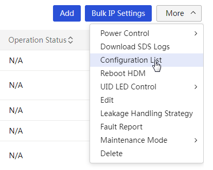
1. In the navigation pane, select Menu > Devices > Server List.
2. To delete servers, select the servers, click More in the top left corner, and then select Delete.
3. To edit servers, select the servers, click More, and then select Edit.
4. Create a label for the servers.
Launch a remote console
About this task
Perform this task to launch a KVM or H5 KVM remote console to configure and manage a server and install the operating system. Only an account with the KVM remote control privilege can start the remote console. A maximum of four concurrent remote control sessions are supported.
A flashing UID LED indicates that the remote console on a server is active.
Procedure
1. In the navigation pane, select Menu > Devices > Server List.
2. Click the KVM or H5 KVM in the Actions column for the target server.
Manage switches
About switch management
Perform this task to add switches to UniSystem for management. You can add up to 30 switches to UniSystem.
Application scenarios
You can add switches to UniSystem for management.
Configuration workflow
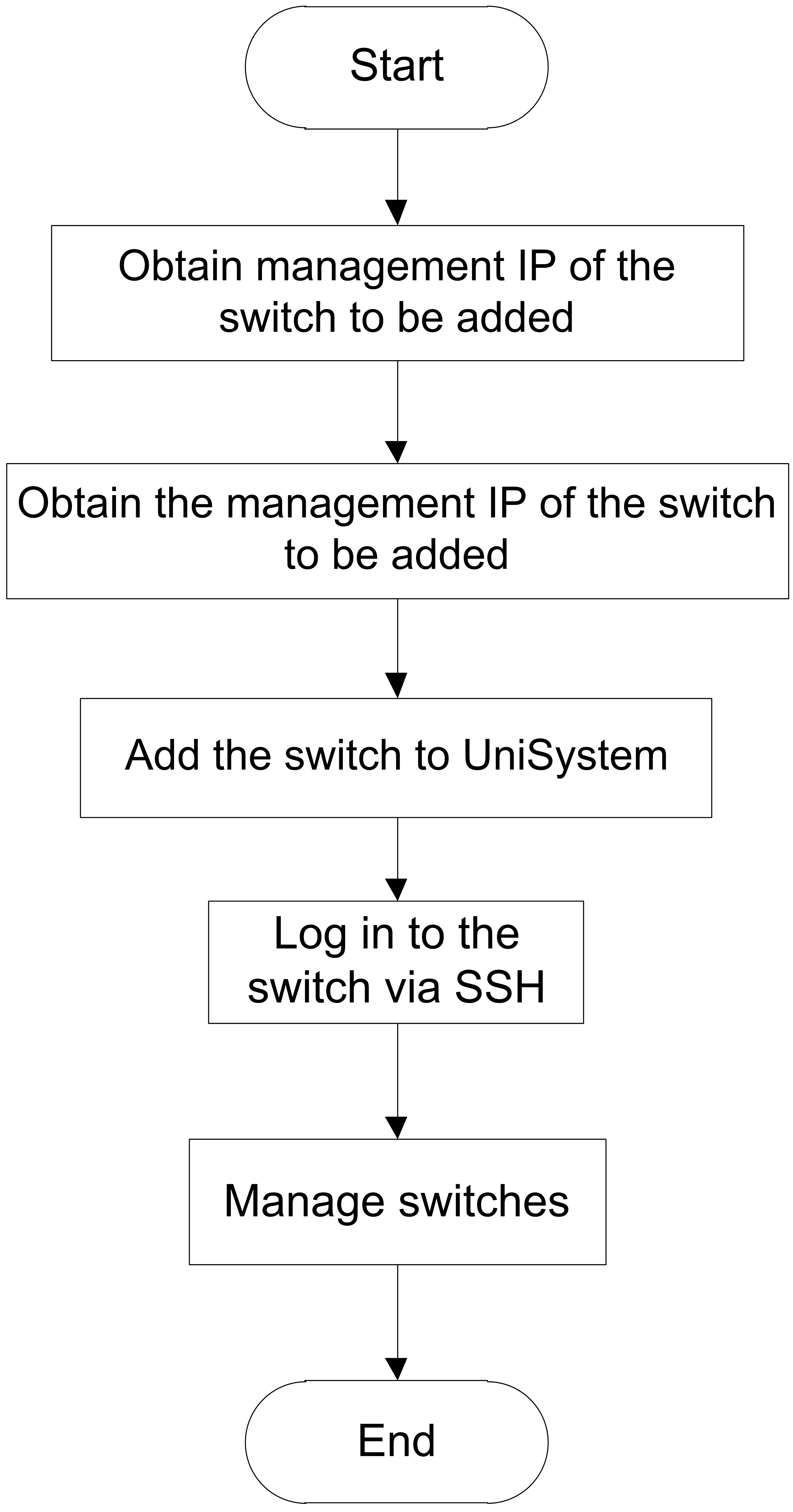
Figure 13 shows the switch management configuration workflow.
Figure 13 Switch management workflow
Prerequisites
· Obtain the management IP address of the switch.
· Obtain the username and password of the system user that has admin privilege to manage the switch, and enable the HTTP service for the user.
· Enable NETCONF over SOAP on the switch.
· Make sure the network where UniSystem resides and the management network of the switch to be added can reach each other.
Restrictions and guidelines
UniSystem can manage the following switches:
· H3C S6800-54QT
· H3C S6850-56HF
· H3C S6800-54QF
· H3C UIS M8380-C
· H3C UIS M8310
Procedures
Add switches to UniSystem
1. Obtain the management IP address of the switch and the username and password of the system user that has the admin privilege to manage the switch.
2. Log in to the switch from the CLI and perform the following steps:
# Enable HTTP-based NETCONF over SOAP.
[Sysname] netconf soap http enable
# Enter user view. This step specifies user admin as an example.
[Sysname] local-user admin
# Enable the HTTP service for user admin.
[Sysname-luser-manage-admin] service-type http
3. Add an IP address that belongs to the management network of the switch on UniSystem.
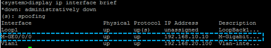
Execute the display ip interface brief command on the switch. The IP address of interface M-GE 0/0/0 is the management IP address of the switch.
Figure 14 Obtain the management IP address of the switch
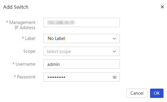
4. Add the switch to UniSystem.
a. Log in to UniSystem. In the navigation pane select Menu > Devices > Switch List.
b. Click Add Switch.
c. In the dialog box that opens, enter related information and click OK.
Figure 15 Add a switch
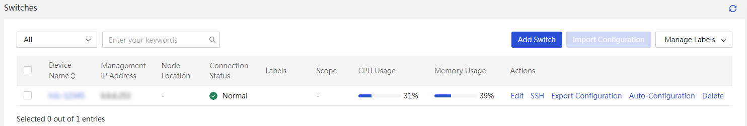
5. Verify that the newly added switch is displayed on the switch list.
Figure 16 View the switch list
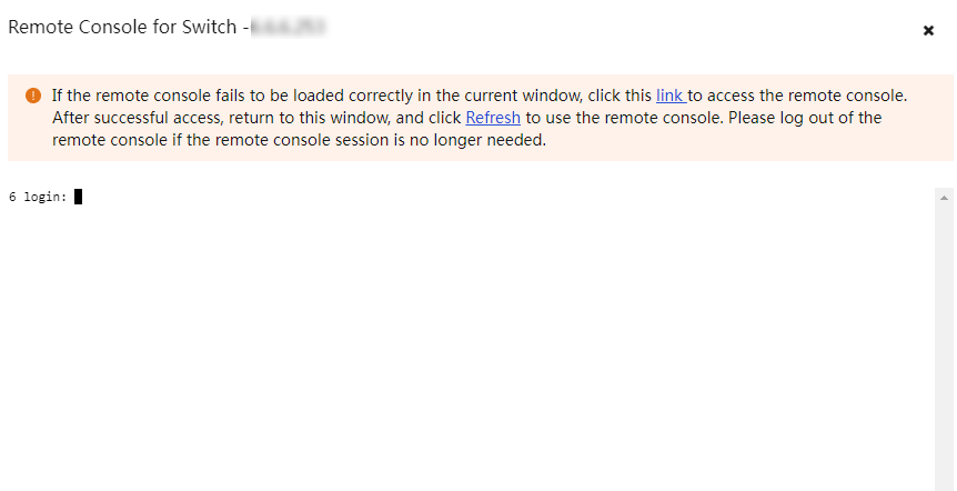
Log in to a switch through the SSH console
Procedure
1. In the navigation pane, select Menu > Devices > Switch List.
2. Click SSH in the Actions column for the switch.
3. Log in to a switch through SSH
Restrictions and guidelines
· If the SSH remote console window fails to be loaded correctly, click the link provided at the bottom of the window to load the certificates on a new page. After the load is completed, return to the remote console window and click Refresh. If you will not use the SSH console for a long period of time, execute a command to exit the SSH console.
· When you are using the SSH console to log in to the CLI of the managed switch, do not click Refresh. If you click Refresh in this case, you will be logged out.
Import and export the switch configuration
|
|
NOTE: Only the H3C S6850-56HF and H3C S6800-54QF switches support this feature. |
Perform this task to export the running configuration of a switch to UniSystem. You can save the exported switch configuration in a switch configuration template and import the related configuration to another switch. You can import or export the configuration for only one switch at a time.
Procedure
1. In the navigation pane, select Menu > Devices > Switch List.
2. Export the switch configuration.
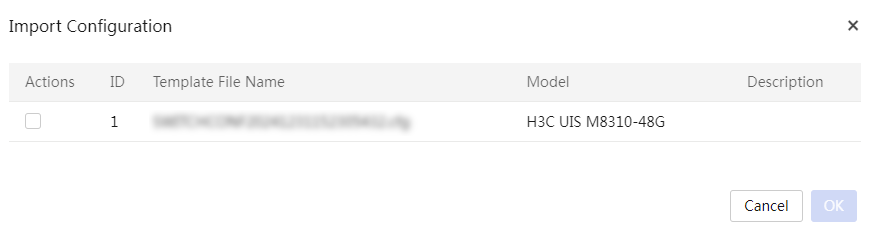
3. To import the switch configuration, select a switch and click Import Configuration. In the dialog box that opens, select the configuration template you want to import to the switch, and then click OK.
Figure 17 Selecting a configuration template to import to the switch
Restrictions and guidelines
· Do not operate switches through CLI, SNMP, or other methods while UniSystem is exporting the switch configuration.
· Configuration export is a resource-intensive operation. Make sure the switch has enough resources before you export its configuration.
· Do not set the name of a switch configuration file to UniSystem.cfg when you save or upload the switch configuration file.
· After you import configuration to a switch, UniSystem might fail to communicate with the switch because of switch IP conflicts. To resolve the issue, manually edit the IP address of the switch and add the switch to UniSystem again.
· Do not import configuration to a switch on which the configuration export is in progress.
· You can import configuration to a switch only by using a switch configuration template from another switch of same model.
· Do not operate switches through CLI, SNMP, or other methods while UniSystem is importing the switch configuration.
· Configuration import is a resource-intensive operation. Make sure the switch has enough resources before you import configuration to it.
Configure auto-configuration
About this task
The auto-configuration feature allows you to bind a server template to a switch port to enable automated configuration of the switch port and the server connected to that port.
When a server is added to UniSystem, UniSystem checks the following items:
· Whether the management port of the server is correctly connected to a switch port that has a bound server template.
· Whether the auto-configuration feature is enabled on UniSystem.
If yes, UniSystem will automatically apply the bound server template to the server and configure the switch port according to the connection settings in the server template.
Procedure
1. In the navigation pane, select Menu > Devices > Switch List.
2. Click the device name of a switch to enter the details page.
3. Click the Auto-Configuration tab.
4. Select the switch ports and bind a server template to these switch ports.
5. Enable Auto-Configuration.
Restrictions and guidelines
· UniSystem can apply the bound server template of a switch port to the newly connected server only when the server is powered off.
· LLDP must be enabled on the switch ports for the auto-configuration feature to work correctly.
Manage templates
Manage enclosure templates
About enclosure templates
By configuring an enclosure template, you can apply each blade server slot in the enclosure with a separate server template and deploy configurations to the entire enclosure at a time. In an enclosure template, each server template is associated with a specific blade server slot. Once a new blade server is inserted into the slot, UniSystem deploys the server template to the server to achieve fast configuration.
Application scenarios
Deploy configurations to the entire enclosure at a time and fast achieve automatic template-based configuration of newly installed blade servers.
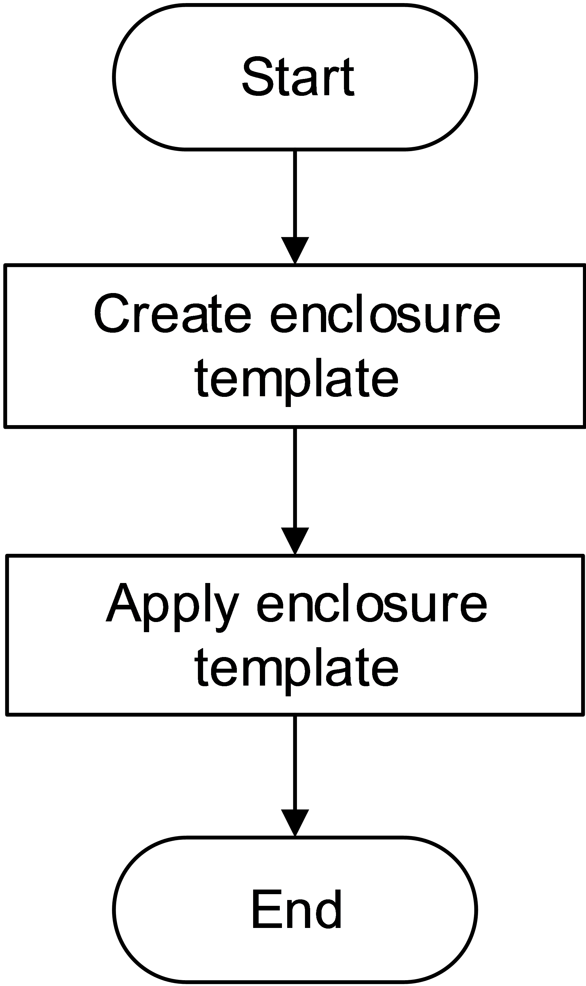
Configuration workflow
Figure 18 shows the enclosure template application process.
Figure 18 Enclosure template application workflow
Restrictions and guidelines
· For a full-width blade server installed in two slots, if the left slot and right slot are applied with different server templates, the template applied to the left slot takes effect on the blade server.
· For the connection settings in an enclosure template to take effect, you must preconfigure VC before applying the enclosure template.
· If a slot of an enclosure is bound to a server template that contains the VC configuration, the VC configuration takes effect only when an closure template or file is applied. If you apply the server template directly, the VC configuration does not take effect.
Procedures
Create an enclosure template
1. Access the Enclosure Templates page.
2. Click Add.
3. Enter the template name and description (optional).
4. Select a server template for each blade server slot. For information about configuring a server template, see "Manage server templates."
Figure 19 Create an enclosure template
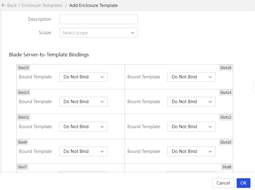
5. Click OK.
Apply an enclosure template
1. Access the Apply Enclosure Templates page.
Figure 20 Apply an enclosure template
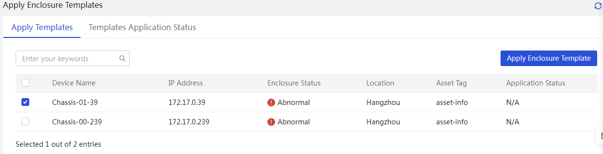
2. Select the target enclosures, and click Apply Enclosure Template. In the dialog box that opens, select the template.
Figure 21 Select an enclosure template
3. The Template Application Status tab opens, displaying the template application status.
Manage server templates
About server templates
In a server template, you can define HDM, BIOS, HDM online, connection, RAID, OS installation, and driver installation settings for servers.
You can apply a server template to multiple servers in bulk.
Application scenarios
Automatically deploy configurations to newly installed blade servers to achieve fast service delivery.
Configuration workflow
Figure 22 shows the server template application process.
Figure 22 Server template application workflow
Restrictions and guidelines
· Before applying an HDM/BIOS template, make sure the HDM or the BIOS of the target server is in normal state.
· Before applying an HDM template, make sure the server model, HDM version, and hardware configuration defined in the template are the same as the actual specifications of the target server.
· Before applying a BIOS template, make sure the server model, BIOS version, and hardware configuration defined in the template are the same as the actual specifications of the target server. The BIOS configurations take effect after the server restarts.
· After you import HDM configurations, HDM restarts automatically.
· When you apply HDM configurations in HDM-1.11.19 or an earlier version (including all HDM-1.10.XX versions), the configuration import policy of UniSystem is the same as the policy of HDM. If you copy the HDM configurations to multiple servers, HDM IP conflicts might occur. Use this feature with caution.
· When you apply HDM configurations in HDM-1.11.20 or a later version, UniSystem does not edit the HDM IP settings. To avoid IP conflicts, do not configure the same IP address for multiple HDMs.
· If you apply an HDM template to servers, the IP, VLAN, and LLDP settings in the template will not take effect in UniSystem-2.31 or a later version.
· Make sure the storage controllers to be configured are of the same model as the model specified in the RAID settings. If two storage controllers are specified in the RAID settings, make sure the corresponding controllers are present and are of the same model.
· Make sure the RAID member drives are present and operating properly.
· Make sure the OS image file exists and is used to install the same OS as specified in the server template.
· To install a Windows operating system, make sure the capacity of the target RAID array meets the primary partition requirements in the server template.
· To avoid affecting system operations, make sure the target server is shut down before applying a server template.
· Before applying a server template, make sure no operations are in progress on the target server. During the template application process, do not perform any operations specified in the template.
· During the template application process on a server, do not perform the following tasks:
¡ Perform power tasks, such as power-off or restart tasks.
¡ Update, reset, or restore the factory defaults for HDM on the server.
¡ Perform mounting tasks through KVM.
· The privilege to apply HDM settings depends on the network privilege of the HDM account. Make sure the user has the privilege to this operation.
· After the HDM settings are successfully applied to a target server, the server will automatically reboot. The HDM status will restore in several minutes.
· To successfully apply the HDM or BIOS settings to a server, make sure the HDM or BIOS version in the template is the same as the HDM or BIOS version of the server.
· For LSI storage controllers, only the RAID mode is supported. Some LSI storage controllers do not require need operating mode configuration.
· As a best practice, do not install an OS through applying a template on a disk of 2 TB or larger. Such an installation might fail.
Procedures
Create a server template
1. Access the Server Templates page.
Figure 23 Manage server templates
2. Click Add.
Figure 24 Create a server template
3. Configure template parameters.
4. Click OK.
Table 10 Description of server template parameters (for Windows operating systems)
|
Item |
Description |
|
OS Version |
Select the operating system version. This field is applicable only to operating systems that support multiple versions. |
|
Host Name |
Name of the host where the operating system is to be installed. If this filed is left empty in the Windows operating system, the Windows operating system automatically assigns a host name. |
|
Primary Partition Capacity |
Capacity of the system partition where the operating system is to be installed, in the range of 51200 to 10485760 MB. If you select Use Full Logical Drive Capacity, the primary partition capacity is set to the maximum value available. To successfully install the operating system, make sure the capacity is no smaller than 50 GB. When the physical drive capacity is large, as a best practice, set the primary partition capacity to the maximum value. (This option is applicable only to the Windows operating systems. In the Linux operating systems, the primary partition capacity is not displayed and uses the maximum available value by default, and the minimum required drive capacity is 80 GB.) |
Apply the server template
1. Access the Apply Server Templates page.
Figure 25 Server Templates page
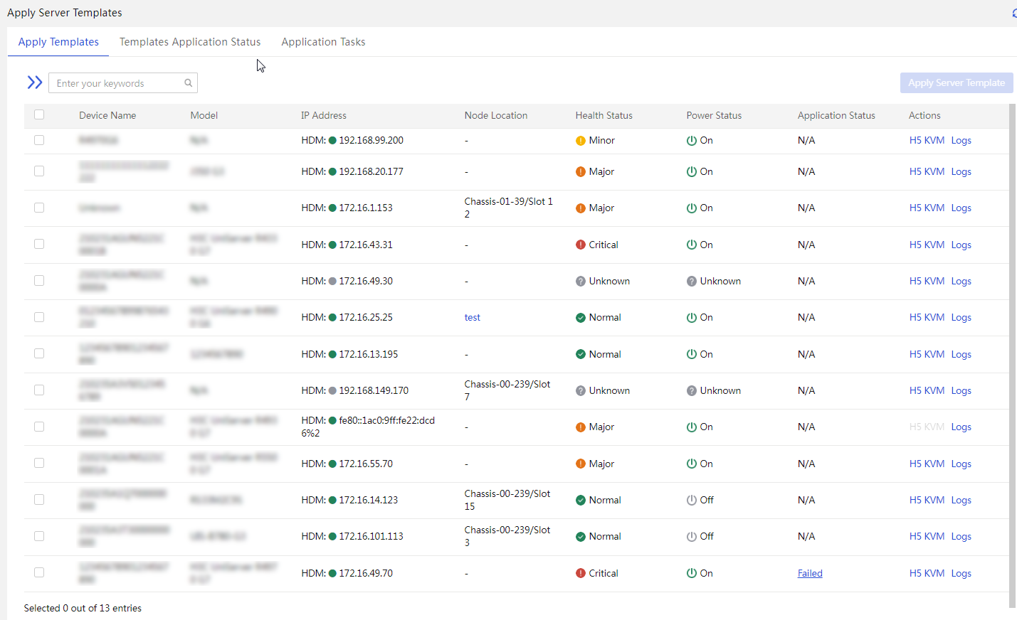
2. Select the target servers, and click Apply Server Template. On the page that opens, perform the following tasks:
|
|
NOTE: To quickly filter out the target server, use the left navigation pane or enter a keyword in the search area. |
3. Select the server template to apply and verify the device name and device status.
Figure 26 Apply a server template
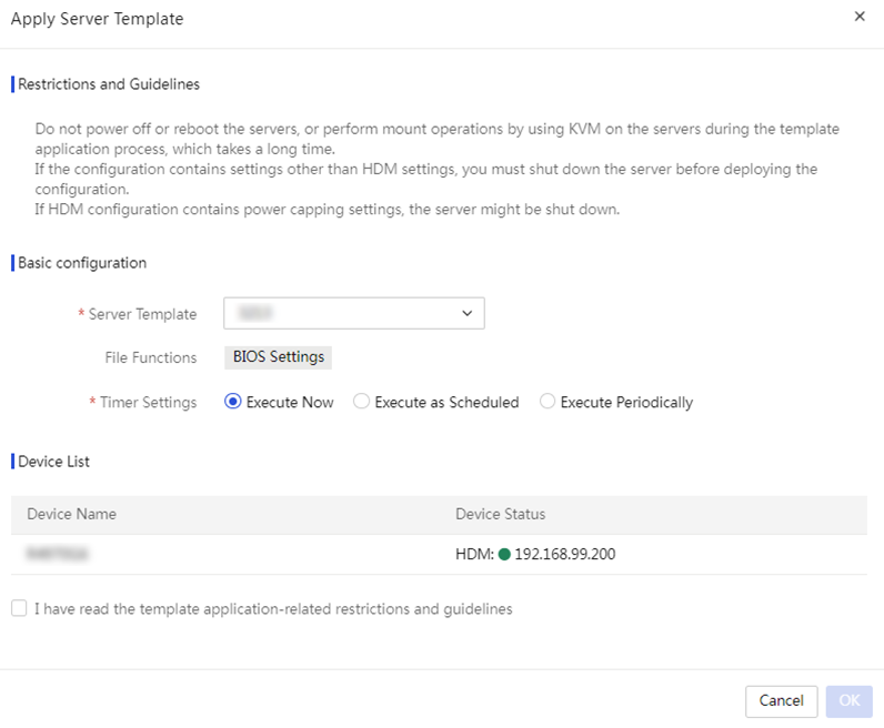
4. Configure scheduled deployment. If you enable scheduled deployment, select a time at which UniSystem will apply the template. If you disable scheduled deployment, UniSystem starts to apply the template once the application process is complete.
The Template Application Status tab opens, displaying the template application status and progress. To view detailed template application information about a server, click Logs in the Actions column for the server.
If you enable scheduled deployment, the application task page opens after the template is applied. On this page, you can see the task execution state.
¡ To stop an application task, click Stop in the Actions column for that task.
¡ To delete an application task, click Delete in the Actions column for that task.
Manage repositories
About repository management
UniSystem allows users to add, edit, delete, inventory, and customize repositories.
A repository is a compressed file containing various drivers for various optional cards and the system board and containing various firmware for HDM, BIOS, CPLD, drives, and optional cards. The firmware and drivers are collectively referred to as components.
Application scenarios
Use this feature together with the component update feature to bulk update the firmware and drivers for servers.
Configuration workflow
Figure 27 shows the repository management process.
Figure 27 Repository management workflow
Prerequisites
Download the repositories.
Restrictions and guidelines
To update drivers through repositories, make sure the managed servers have FIST SMS installed.
Procedures
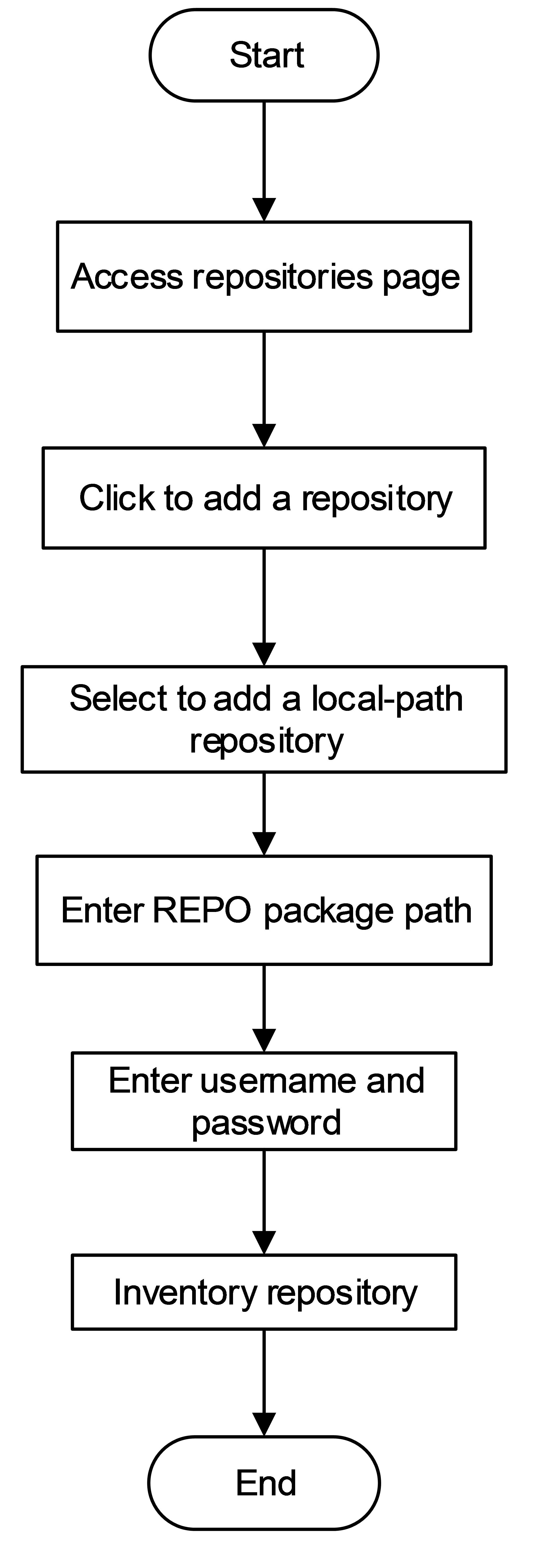
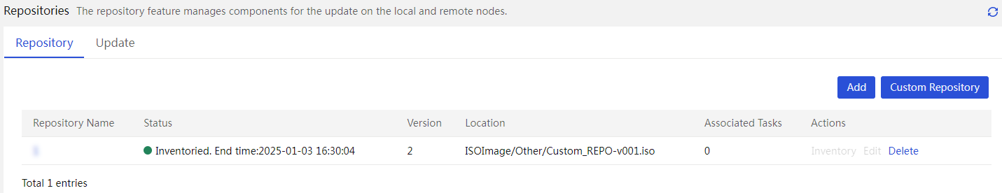
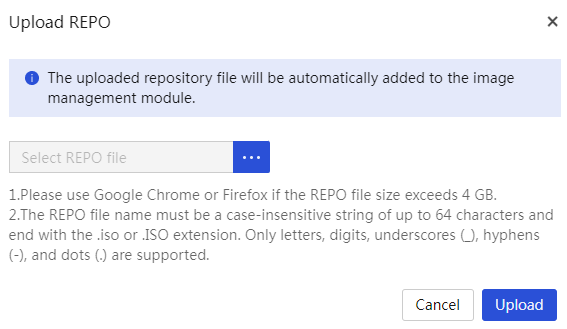
Add a repository
1. Access the Repositories page.
2. Click Add Repository. In the dialog box that opens, configure parameters as needed.
¡ If you select Local Path, perform the following tasks:
- Click Upload.
- In the dialog box that opens, select the repository file, and then click Upload.
- Click Upload to complete adding the repository.
|
|
NOTE: The locally added repository is also added to the image list. You can access the Menu > Templates > Images page to view the repository. |
Figure 29 Add a local repository
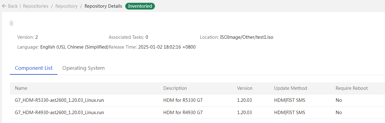
Inventory a repository
1. Click Inventory in the Actions column for the target repository. UniSystem will automatically inventory the repository. After the process is completed, the Status column for the repository displays Inventoried and the end time.

2. View repository details.
Manage address pools
About address pool management
Perform this task to create, edit, delete, and view IPv4 address pools, IPv6 address pools, and host name pools. After creating address pools, you can select a host name pool, IPv4 address pool, or IPv6 address pool rather than manually configure it in the OS Settings area when adding a server template. This feature significantly improves the configuration efficiency.
Application scenarios
Install operating systems in bulk and configure static IP addresses and host names.
Configuration workflow
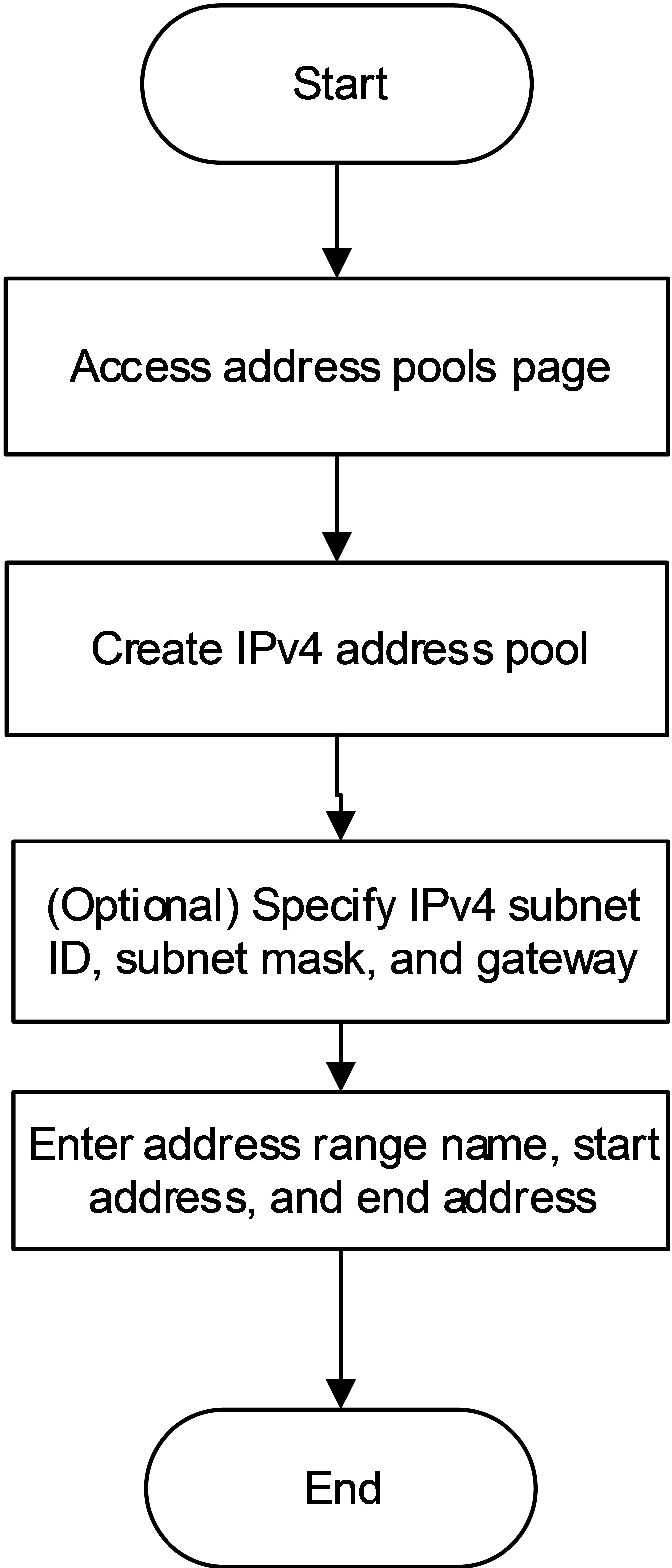
Figure 32 shows the workflow for creating an IPv4 address pool.
Figure 32 IPv4 address pool creation workflow
Procedures
Create an IPv4 address pool
1. Access the Address Pools page.
2. Create an IPv4 address pool.
Figure 33 Create an IPv4 address pool
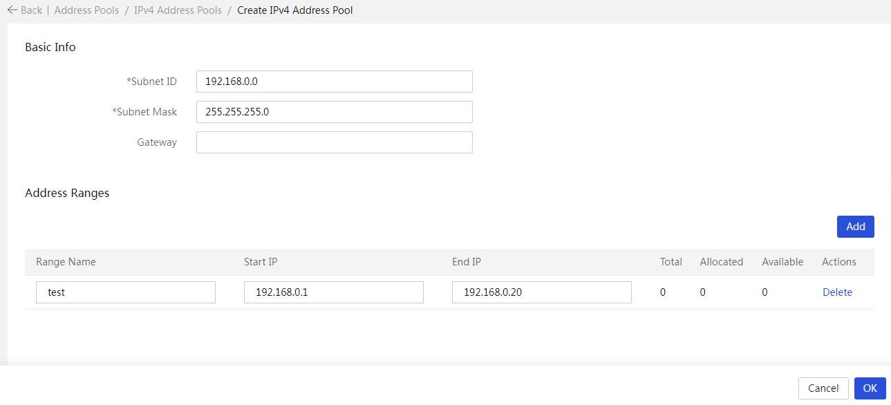
3. Enter the IPv4 subnet ID, subnet mask, and gateway (optional).
4. Click OK.
Manage network templates
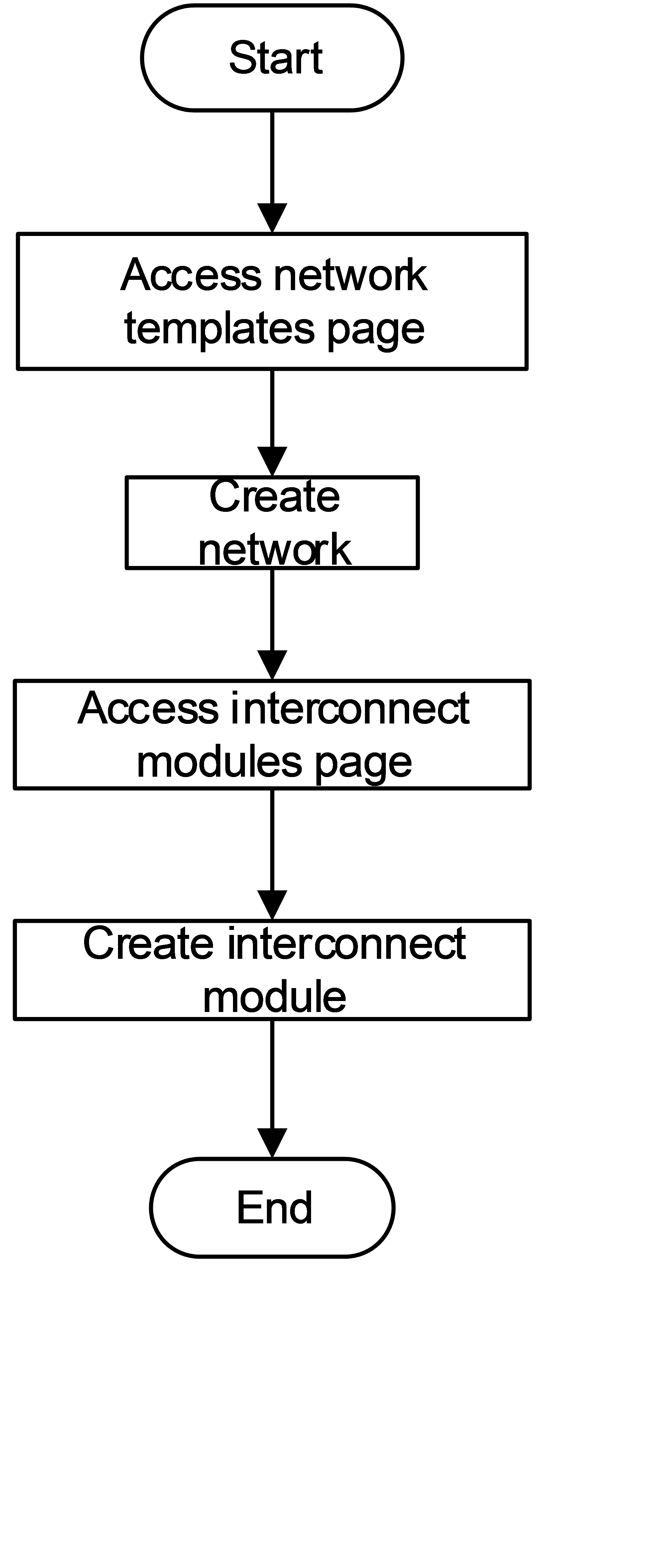
About network template management
Perform this task to create, edit, delete, and view network templates or interconnect module templates.
Application scenarios
Configure the VLAN ID of the switch port connected to the service port of the rack server. Use a network template together with a blade server to configure services for the entire network channel from the service ports of the server to the interconnect module.
Configuration workflow
Figure 34 shows the network template configuration workflow.
Figure 34 Network template configuration workflow
Procedures
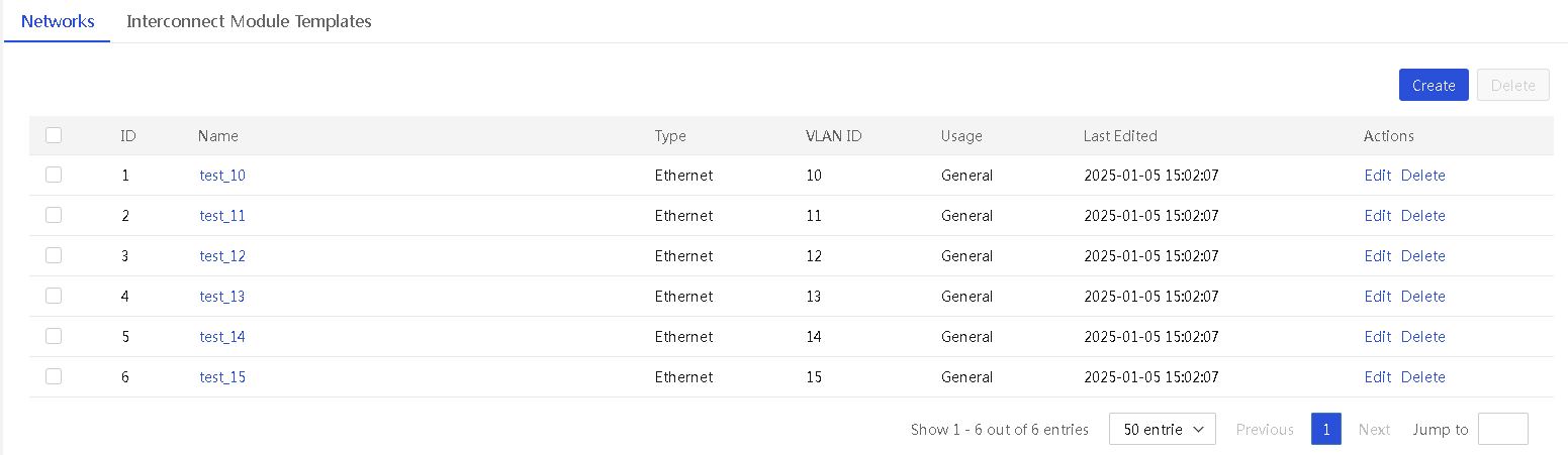
Create a network
Procedure
1. Access the Network Templates page.
2. Click Create. In the dialog box that opens, configure the network parameters. To create interconnect module templates later, you must select VC from the Usage field.

3. Click OK. As shown in Figure 36, UniSystem creates a network for each VLAN.
Create an interconnect module template
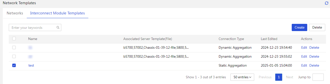
1. Access the Interconnect Module Templates page.
2. Click Create. In the dialog box that opens, configure the interconnect module template. The Network field displays only networks with the usage set to VC.
Figure 37 Create an interconnect module template
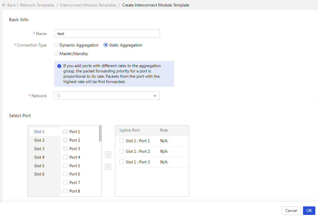
3. Click OK.
Figure 38 Interconnect module template created
Clone images
About image cloning
This feature allows you to perform the following tasks:
· Export images for OS cloning: Export the OS file on the specified logical drive of a server and save the file as an image file. This function supports exporting the following OSs:
¡ OSs manually installed through images mounted to KVM or a USB flash drive.
¡ OSs installed through iFIST.
¡ OSs installed through server templates.
¡ OSs installed through PXE.
· Manage images: Manage image files. You can display image-related information, delete image files, and delete the tags for applying images to blade servers.
The exported image files for OS cloning can be added to the OS settings in a server template and applied. For more information, see "Manage server templates."
Application scenarios
Clone an operating system from one server directly to other servers. This method not only clones the operating system but also supports cloning applications and operating system drivers.
Configuration workflow
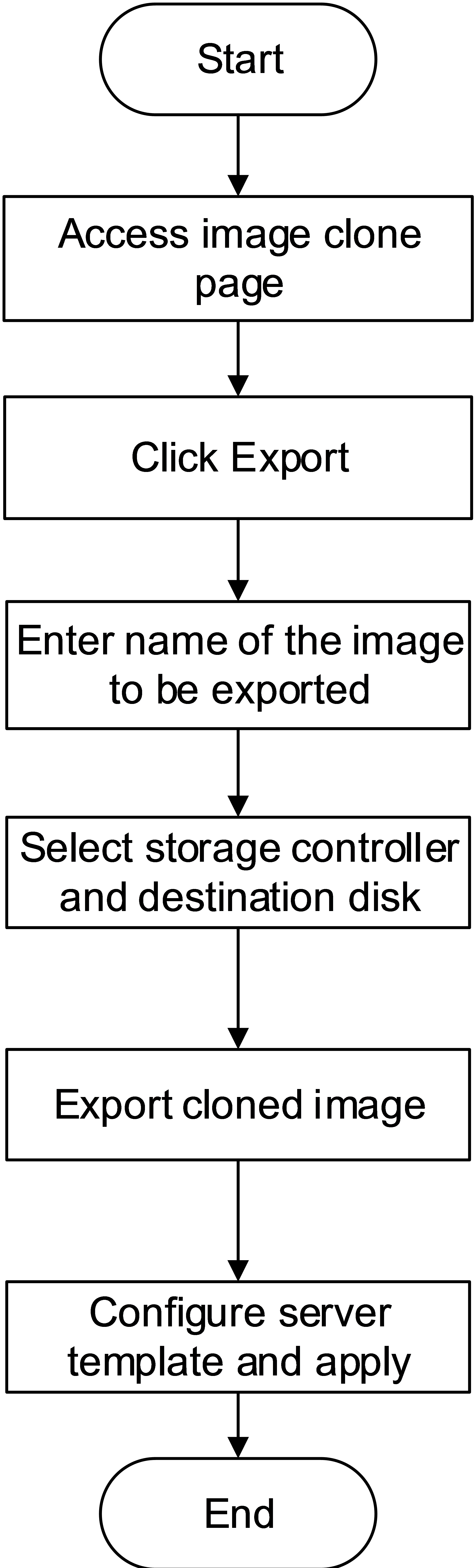
Figure 39 shows the image cloning workflow.
Figure 39 Image cloning workflow
Prerequisites
· This feature is available only when UniSystem runs in the AE module or the VM.
· To use this feature, you must add HDM server nodes to UniSystem first.
· To use this feature, you must install iFIST on the managed servers, and make sure iFIST has a system IP address that can communicate with UniSystem.
· This feature is supported in UniSystem 2.00.13 and later versions.
· This feature supports VMware operating systems in version 2.00.15 and later.
Restrictions and guidelines
· This function cannot export partition-encrypted OSs.
· For LSI storage controllers, only the RAID mode is supported. Some LSI storage controllers do not require need operating mode configuration.
· Before exporting images for OS cloning, make sure the HDM of the server operates properly and the server is powered on.
· Before exporting the OS image from a logical or physical drive on a server, make sure the drive is in valid state and has only one operating system installed.
· When the free space is equal to or smaller than 10 G, you cannot export images for cloning. In this case, delete unnecessary images first. To view the size of the free space, access the Menu > Templates > Images page. During the cloning or export process, do not power off or reboot the server. The process takes several minutes.
· When exporting images for OS cloning, follow these restrictions and guidelines according to the OS type:
¡ Linux
- When the server operates in UEFI mode, you can export only the operating systems installed in UEFI mode. When the server operates in Legacy mode, you can export only the operating systems installed in Legacy mode.
- You can export data in the system partitions (including /, /usr, /usr/local, /var, and /home), but cannot export files in the /run, /proc, /media, or /sys directories or data in the other partitions (including the swap and data partitions).
- After you apply a cloned OS image file to a server, the partition information on the server is the same as the OS before export. Supported file systems include ext2, ext3, ext4, VFAT, XFS, and LVM. The btrfs file system is not supported. LVM thin provisioning supports only the liner mode.
¡ VMware ESXi
- Before exporting images for OS cloning, make sure the OS has been normally shut down once rather than shut down by forcibly powering off, so that the OS can save the configuration file related to the system status. Otherwise, the network settings in the image when you clone and export the image do not take effect.
- Data files of the VMware ESXi operating system cannot be exported. As a best practice, separate the system partitions from the data partitions.
- After applying a cloned image file, to create data partitions in the system logical drive, you must create them manually. Cloned OS images do not support retaining data partitions in the VMware ESXi operating system.
Procedure
1. Access the Clone Images page.
|
|
NOTE: To quickly filter out the target image, you can use the left navigation pane or enter a keyword in the search area. |
2. Click Export in the Actions column for the target server. In the dialog box that opens, specify a name for the task, specify a name for the OS image file to be exported, select a storage controller and a drive, and click OK.
3. You can view the Status column to see the cloning progress.
4. Click Manage Images to enter the image management page. On this page, you can view the type and size of each exported image file.
Configure diskless boot
About diskless boot
Diskless boot refers to a method of starting an operating system without using the drives on the local device. The diskless boot feature in UniSystem follows the iSCSI protocol, providing network-based remote storage volumes for blade servers. You can manually install an operating system on these storage volumes to achieve diskless boot.
Application scenarios
When UniSystem runs on the AE module, the operating system of the blade server must be booted through iSCSI.
Configuration workflow
Figure 40 shows the workflow for configuring diskless boot.
Figure 40 Diskless boot configuration workflow
Prerequisites
· For diskless boot to operate correctly, use the local drives as data drives only, and make sure the local drives have no operating system installed and have no system boot programs.
· Prepare an operating system image.
· Create a storage volume.
· Configure the IP address for the AE module.
Restrictions and guidelines
· This feature is available only when UniSystem runs on the AE module.
· This feature is supported in UniSystem 2.00.13 and later versions.
Procedures
Create a volume
1. Access the Diskless Boot page and view existing iSCSI volumes.
2. Click Create Volume. In the dialog box that opens, enter the volume name and capacity, and click OK.
|
|
NOTE: Make sure the iSCSI volume name complies with the iSCSI Qualified Name (IQN) format (iqn.yyyy-mm.<reversed domain name>[:identifier]), for example, iqn.2014-10.dev.iscsi-target:disk. |
Configure the IP address for the AE module
1. Log in to UniSystem and access the Network Settings page.
2. Confirm the network adapter for communication between the AE module and the target blade server on which the operating system is to be installed based on the above information.
3. Add new IP data and configure the IP address of the iSCSI server.
Configure the network adapter for the blade server
1. Access the port mapping page in the OM. Make sure the network adapter of the target blade server is present and the corresponding interconnect module is present.
2. Access the BIOS Setup Utility of the blade server. Click the Advanced menu, navigate to the mezzanine card based on the slot number and port number, and press Enter to access the submenu.
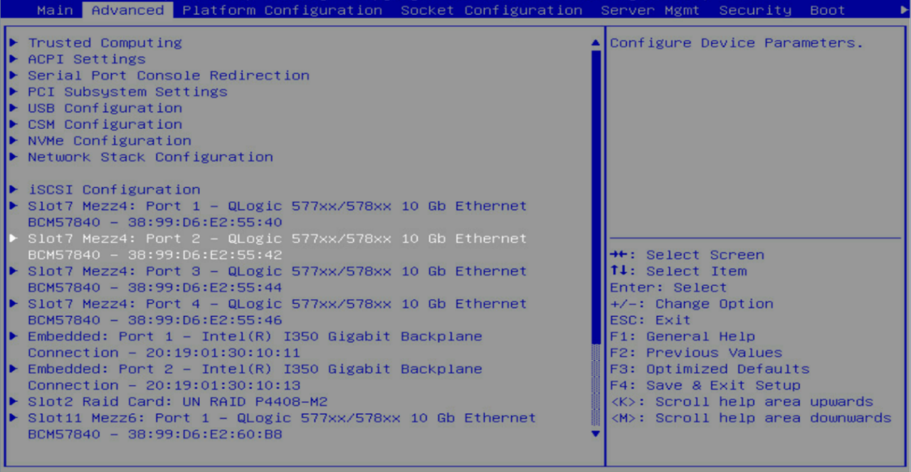
3. Verify that the Link Status is Connected, and press Enter to access the Device Hardware Configuration Menu.
Figure 42 Main Configuration Page
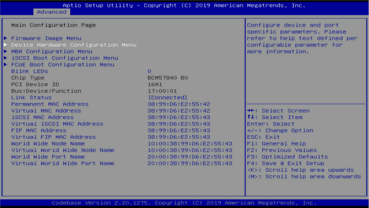
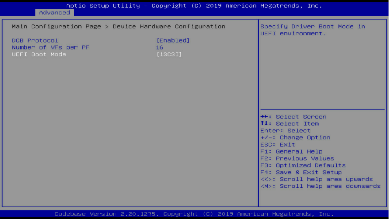
4. Change the UEFI Boot Mode to iSCSI.
Figure 43 Device Hardware Configuration Menu
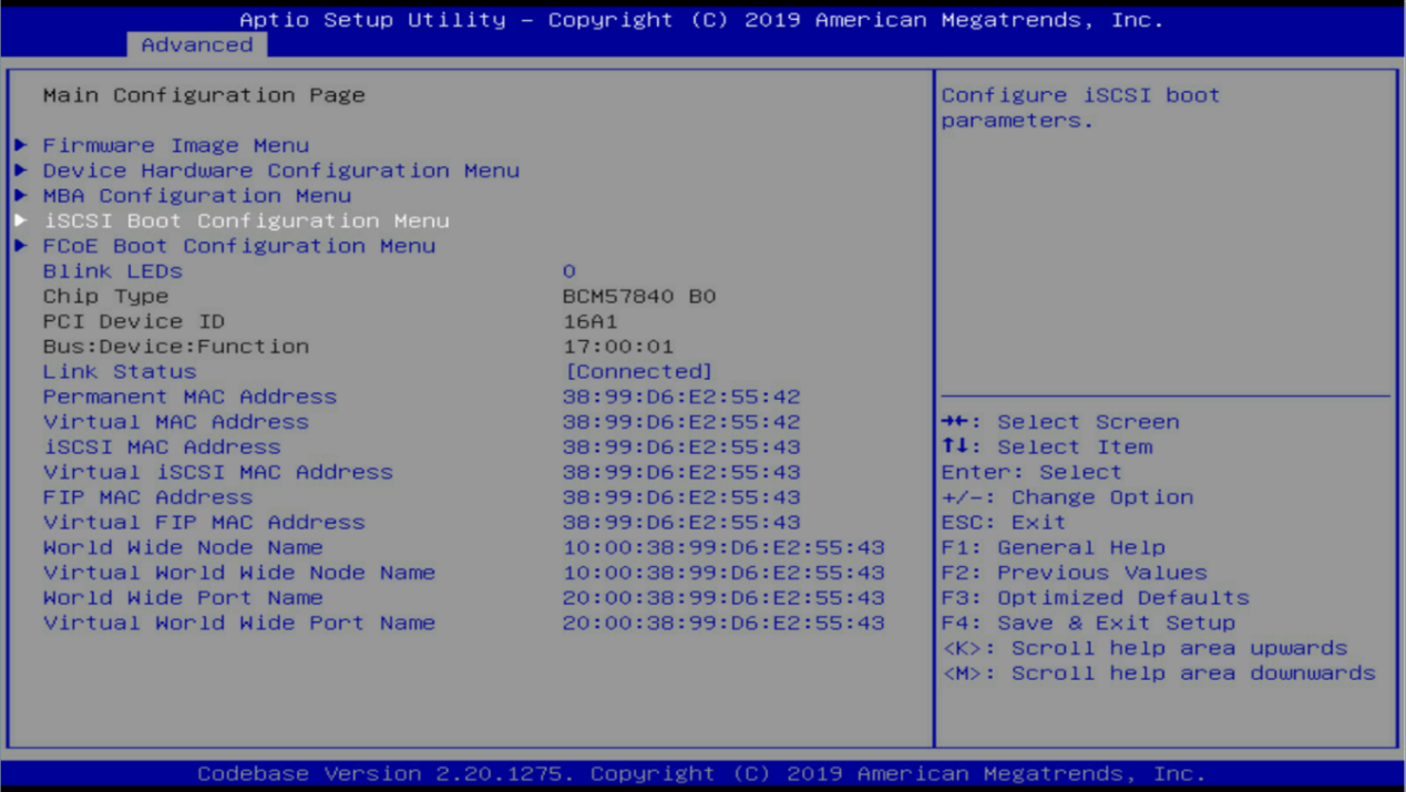
5. Press ESC to return to the previous menu. Select iSCSI Boot Configuration Menu.
Figure 44 Return to the previous menu
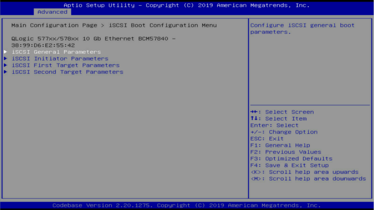
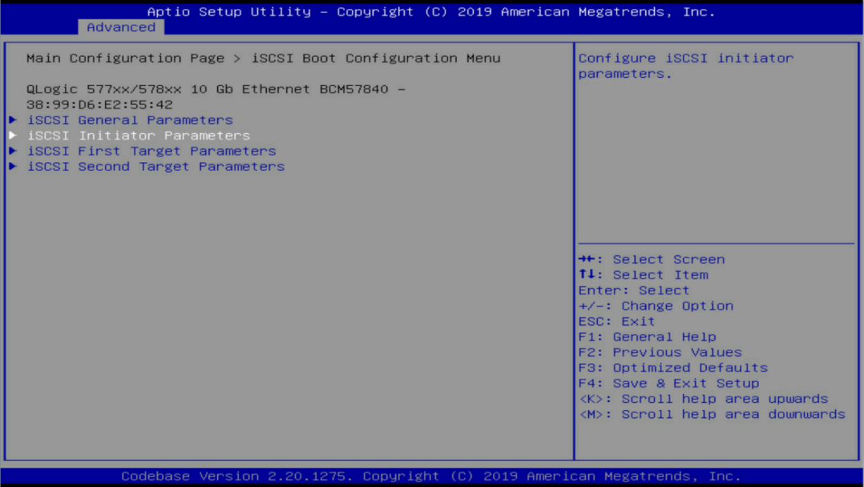
6. Select iSCSI General Parameters, and press Enter.
Figure 45 iSCSI Boot Configuration Menu
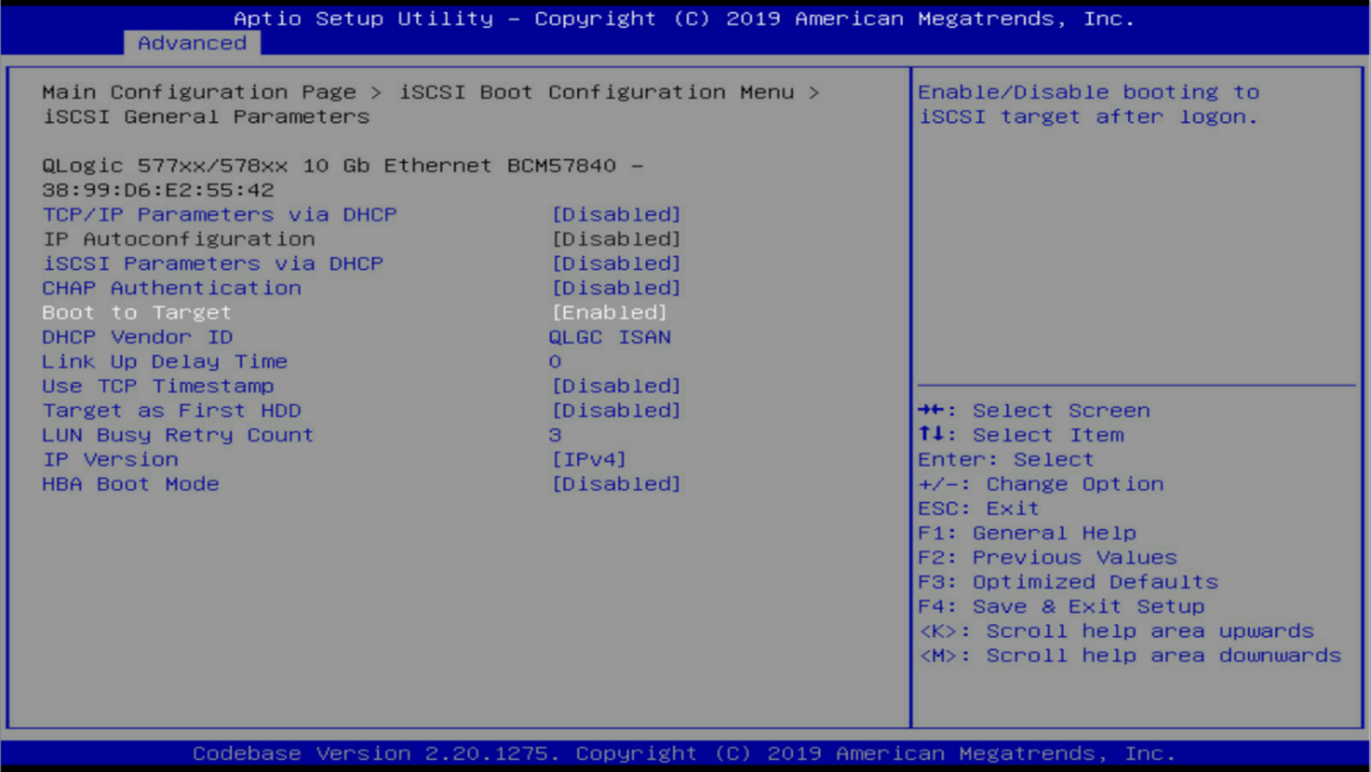
7. Configure the following parameters as needed:
¡ TCP/IP Parameters via DHCP: To use DHCP to assign an IP address to the network adapter, enable this feature. Otherwise, disable this feature.
¡ CHAP Authentication: If authentication is configured for the storage volume, enable this feature. Otherwise, disable this feature.
¡ Boot to Target: Enable this feature.
¡ Retain the default settings in the other fields.
Figure 46 iSCSI General Parameters menu
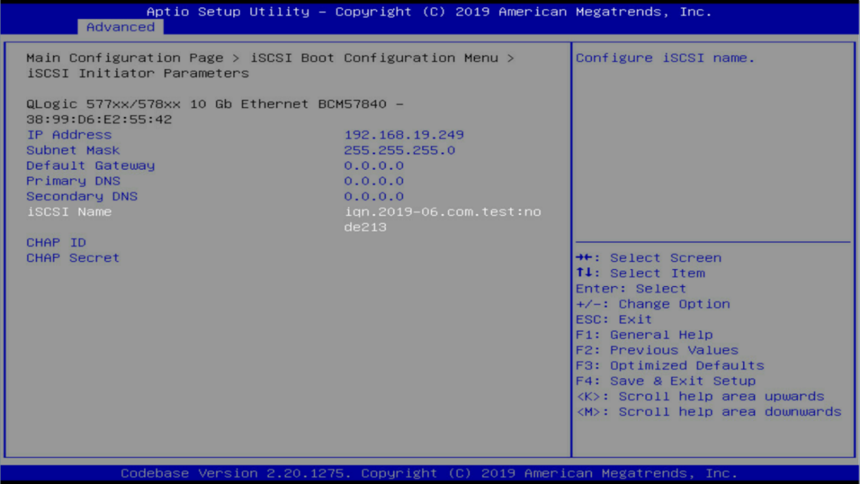
8. Press ESC to return to the previous menu. Select iSCSI Initiator Parameters.
Figure 47 iSCSI Boot Configuration Menu
9. Configure the following parameters:
¡ If TCP/IP Parameters via DHCP is not enabled, specify the static IP address and subnet mask for the network adapter to connect to the iSCSI storage volume.
¡ Configure the gateway and DNS addresses or retain the default settings.
¡ Enter the iSCSI name, the IQN name used by the network adapter to connect to the storage volume. Make sure the IQN is unique in the network.
¡ If CHAP authentication is enabled, specify the CHAP ID and CHAP secret for the storage volume. The CHAP ID and CHAP secret are required here every time after you change the iSCSI target parameters if CHAP authentication is enabled for the storage volume.
Figure 48 iSCSI Initiator Parameters menu
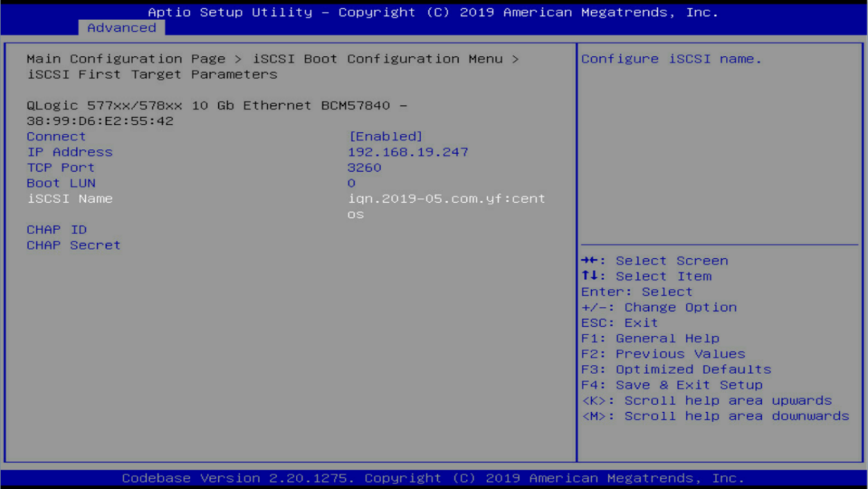
10. Press ESC to return to the previous menu. The iSCSI First Target Parameters menu opens.
Figure 49 iSCSI Boot Configuration Menu

11. Configure the following parameters:
¡ Select Enabled from the Connect field.
¡ Enter the IP address of the iSCSI server in the IP Address field (reachable IP address of the network port on the AE module).
¡ Retain the default settings in the TCP Port and Boot LUN fields.
¡ Enter the IQN of an available target on the AE in the iSCSI Name field.
Figure 50 iSCSI First Target Parameters menu
The configuration is complete. The network adapter configuration takes effect at the next device restart.
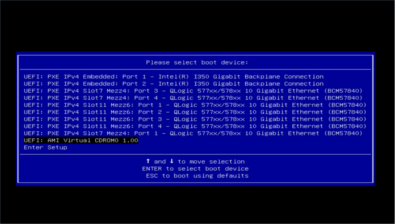
Install an operating system
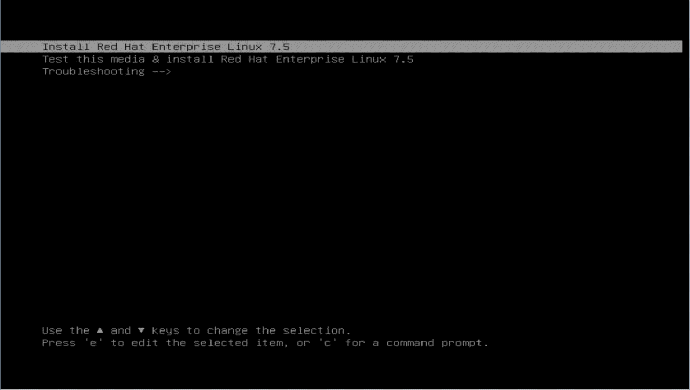
1. Install a Redhat or Centos7.5 operating system
2. Use KVM to mount the standard installation image or use another method to install the operating system on the configured blade server. This section uses the KVM method as an example and use Virtual CDROM as the boot device.
Figure 51 Boot menu
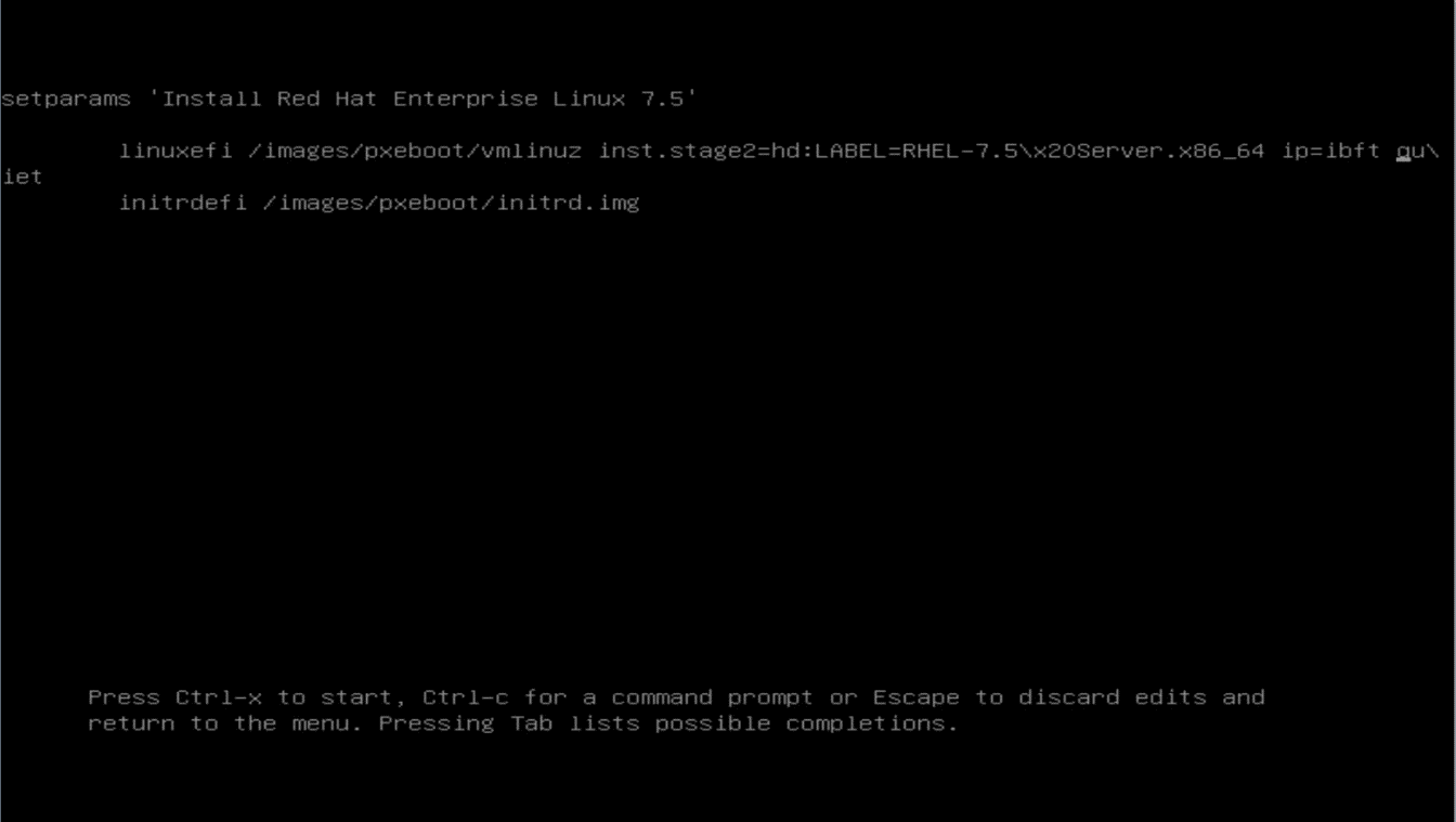
3. When the installation boot menu appears, use the up and down arrow keys on the keyboard to move the cursor to the first or second item, then press e to edit the boot parameters.
Figure 52 Installation boot menu
4. In the editing interface, navigate to the end of the second line, and enter ip=ibft right before quiet. Make sure a space exists before and after your addition. Then, press Ctrl + X to start the installation.
Figure 53 Editing interface
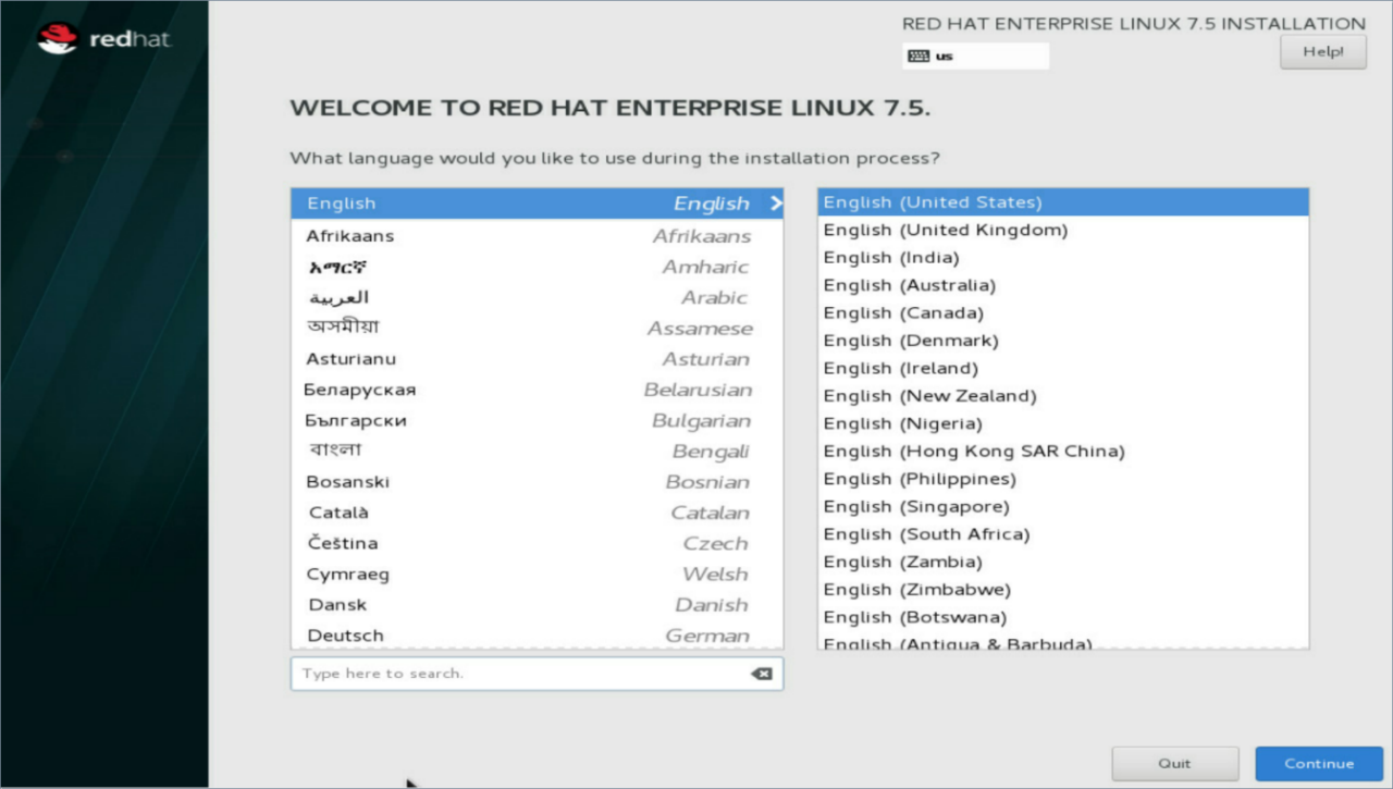
5. Select the system language and click Continue.
Figure 54 Selecting the language
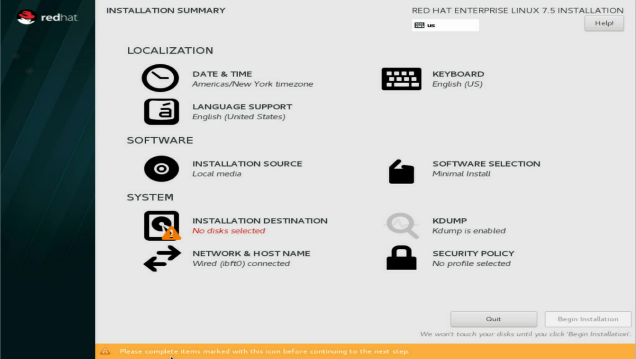
6. On the Installation Summary page, verify that ibft0 connected is displayed below NETWORK & HOSTNAME at the lower left corner. This indicates that the system has successfully read network adapter configuration parameters from the BIOS.
Figure 55 Installation Summary page
7. Click INSTALLATION DESTINATION and select the target disk for installation.
8. Click Add a disk in the Specialized & Network Disks section and select the created iSCSI storage volume. Do not select a local disk.
Figure 56 INSTALLATION DESTINATION
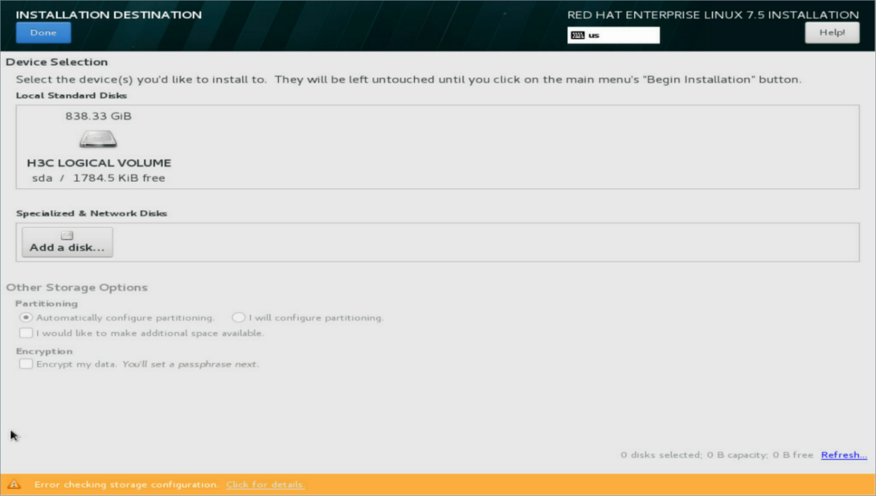
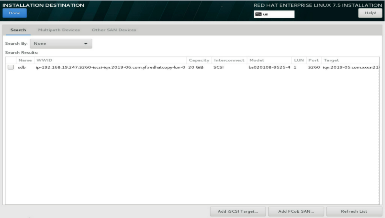
9. The system automatically displays all the iSCSI storage volumes connected to the network adapter. If no iSCSI storage volume is displayed, it indicates that the network adapter configuration is incorrect or the network environment is abnormal. Examine the configuration and network connectivity and try again. Verify that the IQN and capacity are correct, select the iSCSI storage volume, and click Done.
Figure 57 Add a disk
10. Click Full disk summary and boot loader at the lower left corner, and confirm that the Boot field of the iSCSI storage volume is selected, which indicates that the boot loader will be installed on the iSCSI storage volume.
Figure 58 SELECTED DISKS

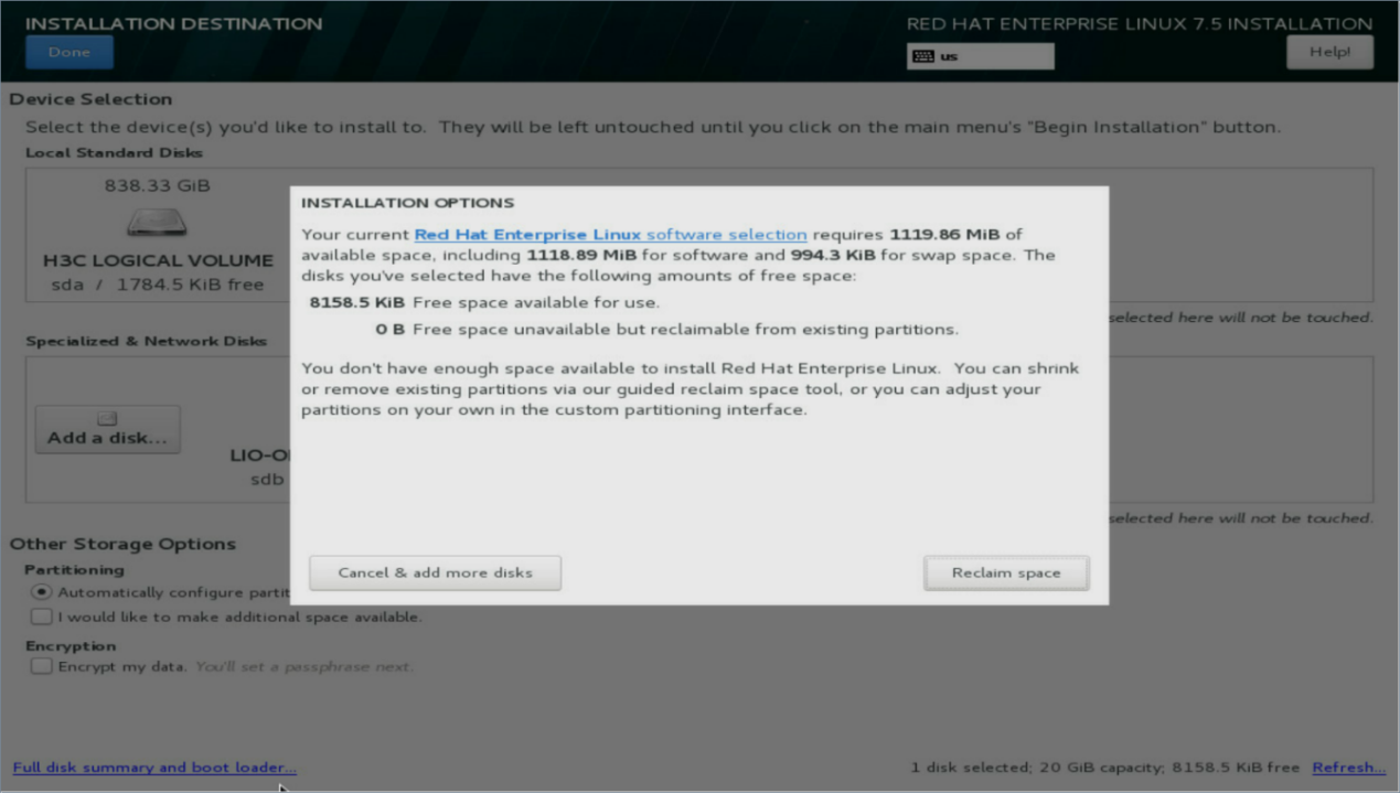
11. Choose either automatic partitioning or manual partitioning as needed. If partitions already exist on the iSCSI storage volume, the system prompts you to confirm the rebuilding of partitions. In this case, click Reclaim space to proceed.
Figure 59 INSTALLATION OPTIONS
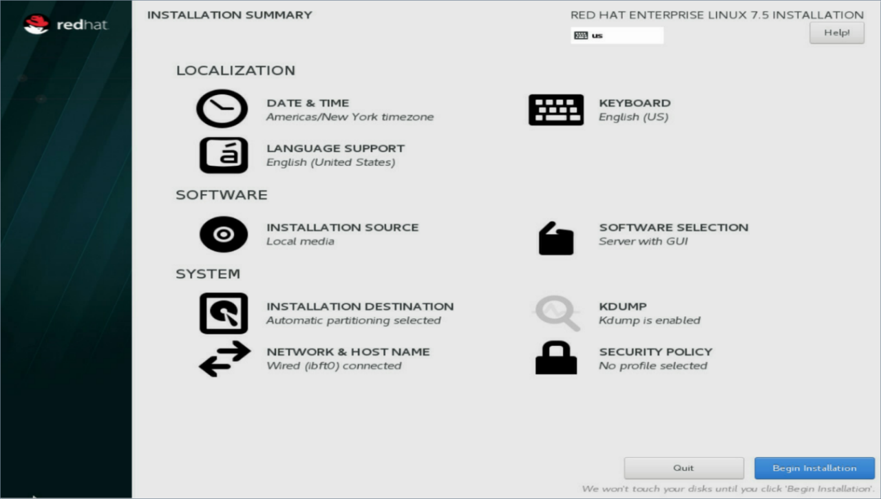
12. Select the software packages and other configurations as needed, and then click Begin Installation. Wait for the installation to complete. For more information, see H3C Servers Operating System Installation Guide.
Figure 60 Return to the installation summary page
13. After the installation, you can restart the device and access the system to use it.
14. To replicate the system for use on other blade servers, you can directly copy the storage volume in UniSystem.
Install the Vmware ESXi 6.5 U2 or ESXi 6.7 operating system
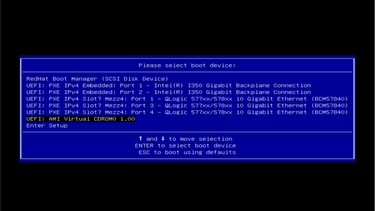
1. Use KVM to mount the standard installation image or use another method to install the operating system on the configured blade server. This section uses the KVM method as an example and use Virtual CDROM as the boot device. This section installs the ESXi 6.5 U2 as an example. The installation procedure is similar for the ESXi 6.7.
Figure 61 Boot Menu
2. After the installation process begins, no additional manual actions are required. Wait for the loading to complete and for the installation interface to appear.
Figure 62 Start installation

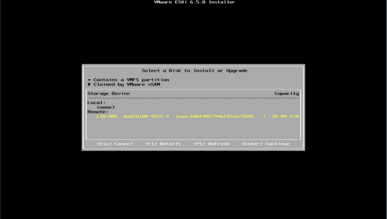
3. At the drive selection phase, the system automatically displays all the iSCSI storage volumes connected to the network adapter. If no iSCSI storage volume is displayed, it indicates that the network adapter configuration is incorrect or the network environment is abnormal. Examine the configuration and network connectivity and try again.
Figure 63 Select drives
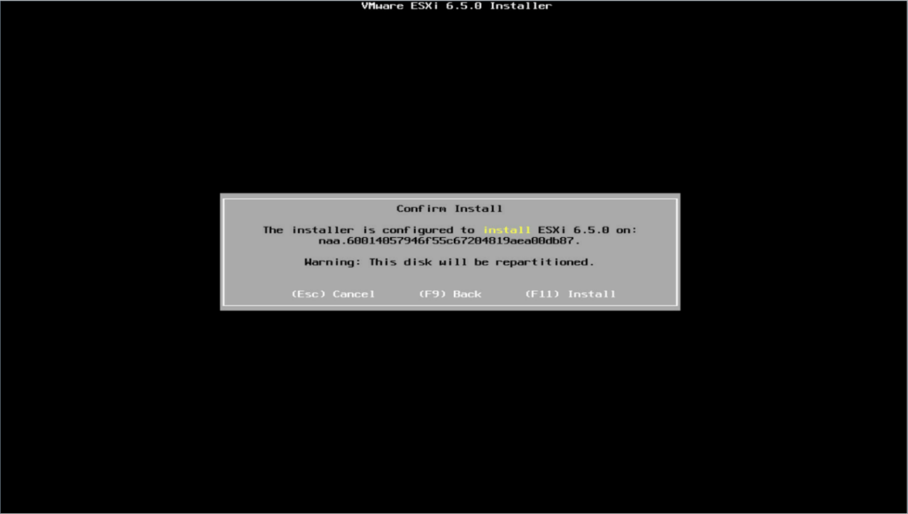
4. After you press Enter, if partitions already exist on the iSCSI storage volume, the system prompts you to overwrite the existing partitions. Press Enter again.
Figure 64 Overwrite existing partitions
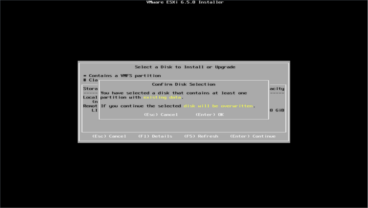
Figure 65 Repartition the storage volume
5. Set the language and root password as instructed and wait for the installation process to complete. After the installation, you can restart the server and access the ESXi system and use it.
·
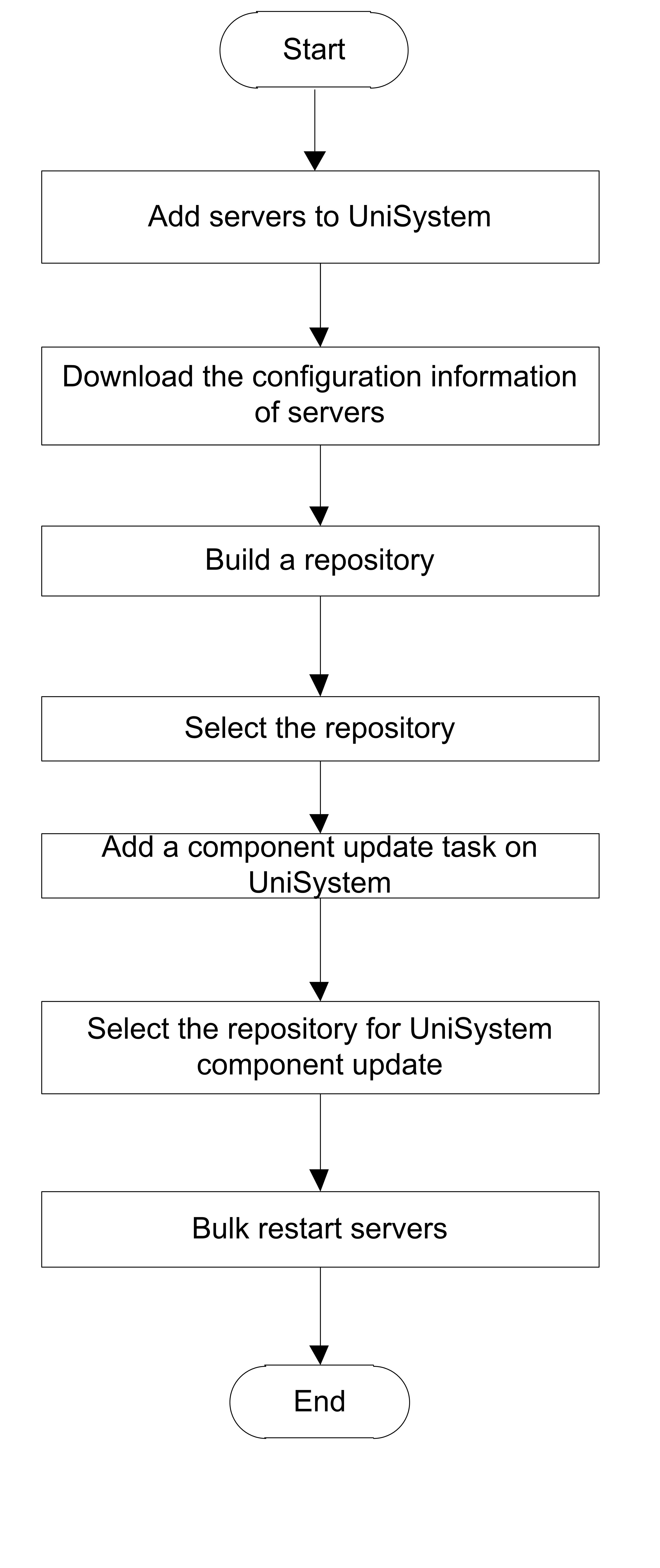
Deploy devices
Update components
About component update
Perform this task to update the components on local and remote nodes. The components include HDM, BIOS, CPLD, and firmware and drivers for the hardware.
Application scenarios
You can bulk update HDM, BIOS, CPLD, and firmware and drivers for the hardware for servers in bulk.
Configuration workflow
Figure 28 shows the component update workflow.
Figure 66 Component update workflow
Restrictions and guidelines
· By default, UniSystem updates the HDM and BIOS firmware with user-configured settings retained.
· Read the release notes for the target firmware before you perform an upgrade. To perform a cross-version upgrade, such as from BIOS 1.00.XX to BIOS 2.00.XX, or to upgrade to a version that does not support retaining the user-configured settings, contact Technical Support.
Procedures
Add servers
1. In the navigation pane, select Menu > Devices > Server List.
2. Click Add.

3. Select Bulk Import.

4. Upload a server template file to bulk add servers.
Export the configuration information of servers
1. Select the servers whose configuration information you want to export, click More, and then select Configuration List.
Figure 71 Export the configuration information of servers
2. Verify the export, as shown in Figure 34.
Build and upload a repository
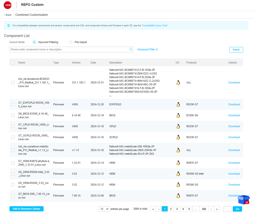
1. Access the REPO Custom page, as shown in Figure 35.

2. Select Combined Customization and customize the REPO package, as shown in Figure 36.
Figure 74 Combined Customization page
3. Select File Import and upload the .json REPO file in the downloaded configuration list, as shown in Figure 37.
Figure 75 Import the component filter

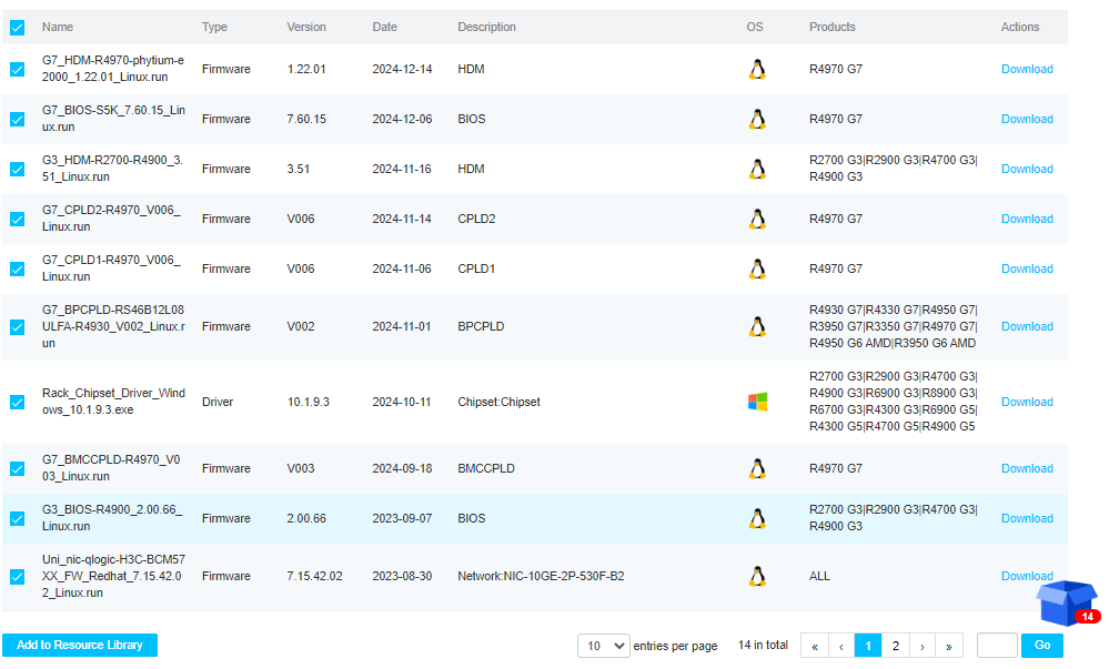
4. Select the components and click Add to Resource Library, as shown in Figure 38.
Figure 76 Filter and add components to the resource library
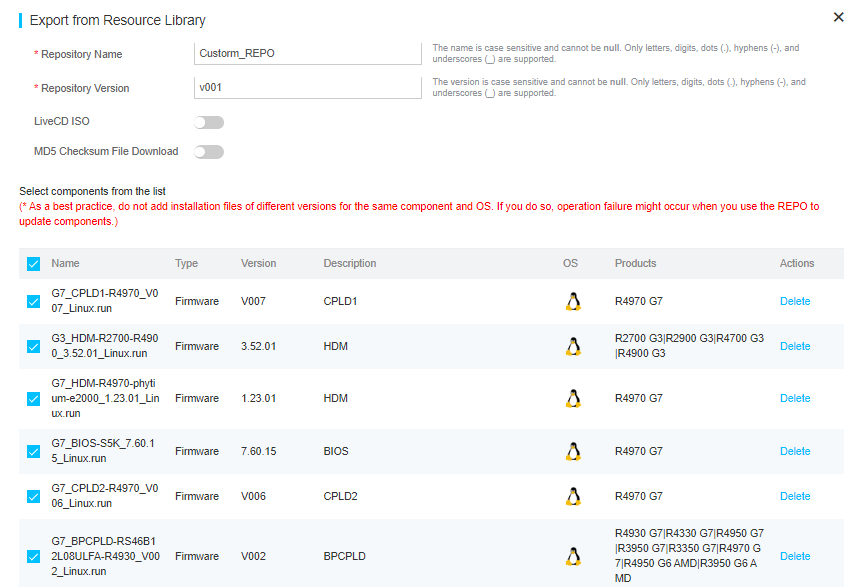
5. Click the resource library and navigate to Repository Name and Repository Version on the resource exporting and downloading page, as shown in Figure 39. Then, click Download.
Figure 77 Download the resource library
6. Return to UniSystem and navigate to the Menu > Templates > Repositories page.
7. Click Add Repository.
8. Select Local Path and upload the repository file that has been downloaded.
9. After you add a local repository to UniSystem, the repository will automatically inventories by UniSystem.
Bulk update components
1. In the navigation pane, select Menu > Deployment > Update Components.
2. Click Add to add an update task.
3. Select the target servers and specify the task name. Select a repository.
4. After the task is added, click Inventory in the Actions column for the task to edit the task.
5. In the dialog box that opens, select the target repository from the Repository list. UniSystem will automatically filter out the applicable components from the repository.
6. After the inventory finishes, the task deployment page opens. The UniSystem will automatically select components in the REPO package that are higher than the installed versions. To update all components, select all components.
Restart servers
1. For the component update to take effect, restart the servers.
2. In the power management dialog box that opens, verify the configuration and click OK to restart the servers.
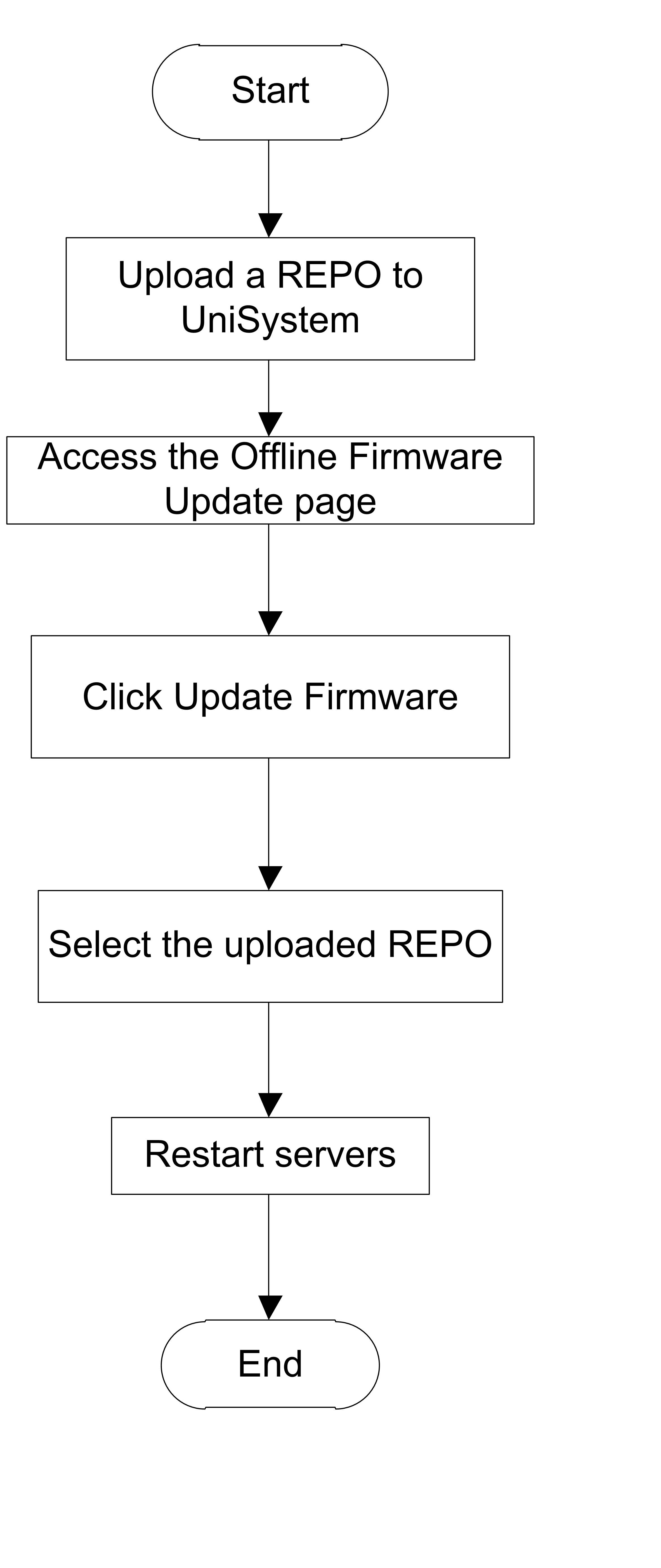
Update firmware offline
About offline firmware update
Offline firmware update are used when servers do not have an operating system and firmware updates cannot be fully completed in an out-of-band manner. To perform offline firmware update, UniSystem must operate with REPOs. UniSystem mounts the REPO image to the server to be updated by using KVM. The server then boots up from the image. After the bootup, the update script is automatically used to complete the firmware upgrade.
Application scenarios
You can update the firmware on servers in bulk by mounting a REPO that includes the LiveCD system.
Configuration workflow
Figure 40 shows the offline firmware update workflow.
Figure 78 Offline firmware update workflow
Prerequisites
· To use this feature, you must add HDM server nodes to UniSystem first.
· Do not perform template application, component update, or other operations on a server while firmware update is in progress on that server.
· Before an update, as a best practice to ensure that the firmware can be updated to the expected version, check the related firmware version information in the REPO.
Restrictions and guidelines
· To ensure successful update, verify that the target server does not have an image mounted through KVM and its USB port is not connected to the USB drive.
· To guarantee the firmware update speed, use the HDM dedicated port as a best practice. If the shared network port is used for firmware update, set the rate of the corresponding NIC on the UniSystem server to 100 Mbps.
· Keep the network stable during the update process.
· To abort the ongoing update process on a server and start a new update process, select the server, and then click Cancel Update first.
· An HDM server node in abnormal state cannot be rebooted.
Procedures
Upload a REPO
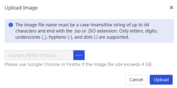
1. In the navigation pane, select Menu > Templates > Images, as shown in Figure 41.
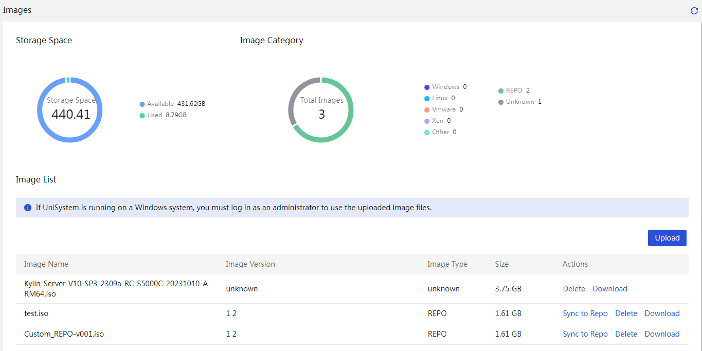
2. Upload an OS image.
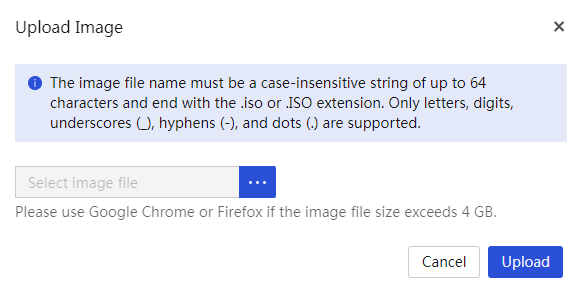
3. Select an OS image file and upload the OS image file to the UniSystem server.
4. Verify that the image file is displayed on the Images page.
5. (Optional.) If the uploaded image file is a repository file, you can synchronize the file to the Menu > Templates > Repositories page.
Update the firmware offline
1. In the navigation pane, select Menu > Deployment > Firmware Update > Offline Firmware Update.
2. Select the target servers, and then click Update Firmware. In the dialog box that opens, select the uploaded REPO file for the update, and then click OK. The update will be performed automatically.
|
|
NOTE: You can search for devices by filtering labels and specifying keywords.. |
Figure 81 Update the firmware offline
3. The update progress is displayed during the update. To view the firmware update progress of a server, click the H5 KVM link in the Actions column for that sever.
4. (Optional.) After the update is completed for a server, click the Update Finished or Update Failed link in the Update Status column for that server to view the update summary.
|
|
NOTE: UniSystem can show the firmware update progress and result for a server only when a repository is used for the update and the server runs HDM 2.11 or later.. |
5. Some firmware products require a reboot to take effect.
Update the firmware by using HDM out-of-band management
About firmware update by using HDM out-of-band management
Perform this task when servers cannot restart immediately due to running services, and only out-of-band networks are available. This feature requires UniSystem to cooperate with HDM, iFIST, and REPO. UniSystem uploads the REPO image to HDM for storage. On the next server reboot, it automatically enters iFIST, which then completes the server firmware update.
Application scenarios
You can update the REPO firmware for servers in bulk.
Configuration workflow
Figure 44 shows the workflow for HDM out-of-band firmware update.
Figure 82 Workflow for HDM out-of-band firmware update
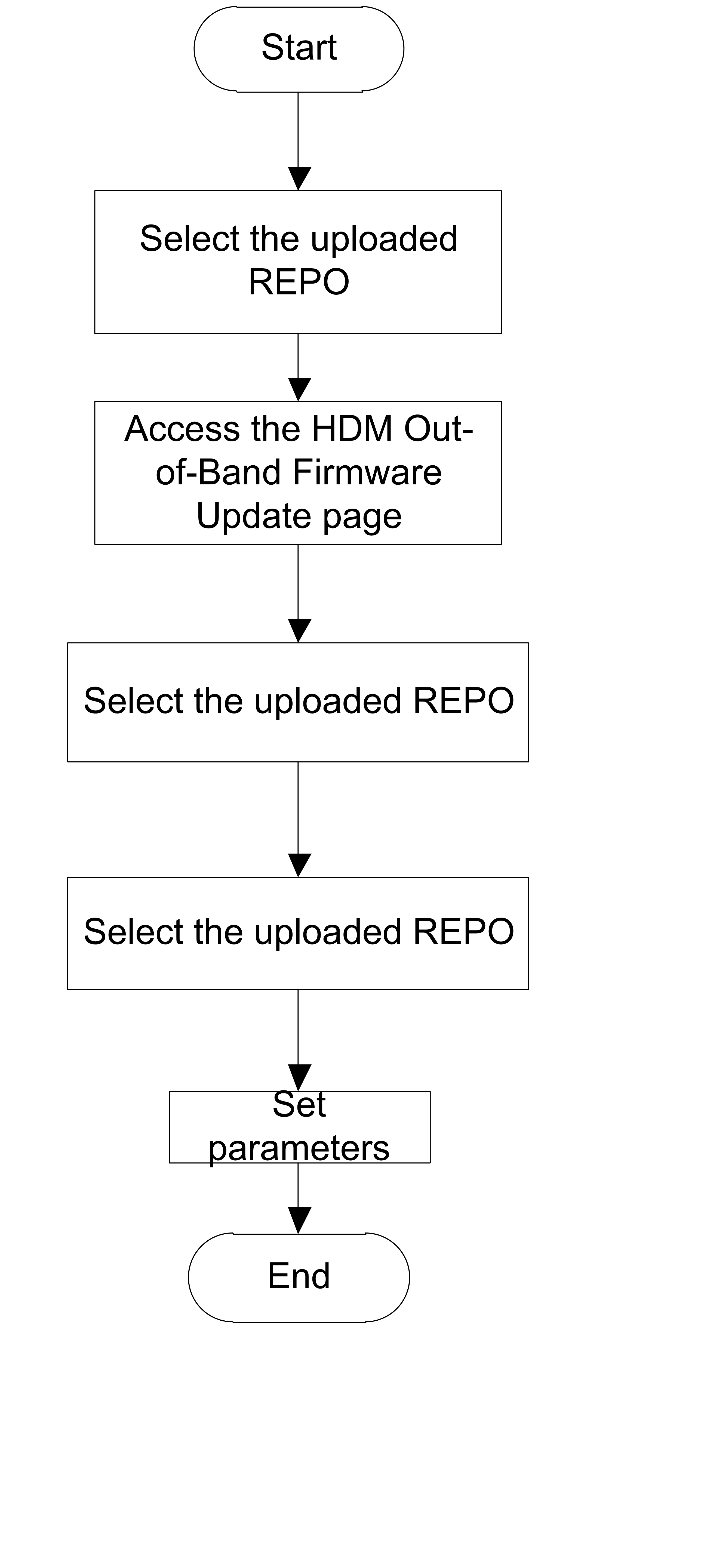
Prerequisites
Upload the REPO to UniSystem.
Restrictions and guidelines
To use this feature, the following requirements must be met:
· UniSystem is used together with HDM and iFIST.
· UniSystem is in UniSystem-2.32 or later versions.
· HDM is in HDM-2.52 or later versions.
· iFIST is in iFIST-1.32 or later versions.
Procedures
Upload a REPO
For more information, see "Upload a REPO."
Perform HDM out-of-band firmware update
1. In the navigation pane, select Menu > Deployment > Firmware Update > HDM Out-of-Band Firmware Update.
Figure 83 HDM out-of-band firmware update
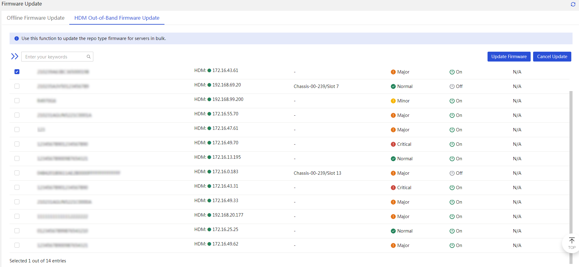
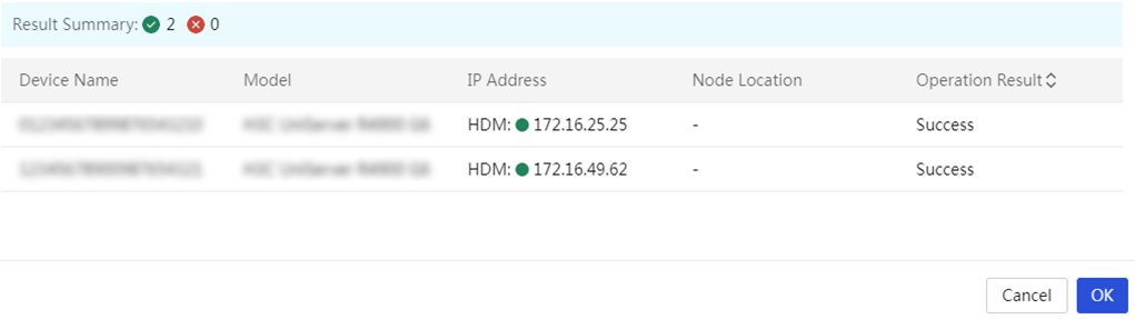
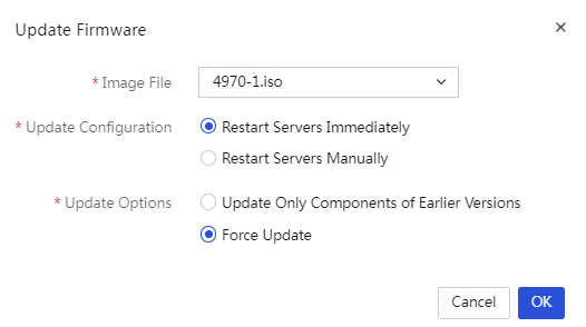
2. Select the target servers, and then click Update Firmware. In the dialog box that opens, select the uploaded REPO file and configure the related parameters. Then, click OK.
|
|
NOTE: You can search for devices by filtering labels and specifying keywords. |
Figure 84 Configure the parameters
3. To cancel ongoing firmware update on servers, select the target servers and then click Cancel Update. In the dialog box that opens, click OK.
If a server is verifying the file for update, you cannot cancel the ongoing firmware update on that server.
Configure monitoring
Configure SMTP settings
About SMTP settings
Perform this task to implement the following functions:
· Send event logs of the managed servers to concerned users to monitor the operating status of the servers.
· Monitor the health status of the managed servers and then send alarm emails to concerned users to notify the health change.
Application scenarios
Users can monitor the operational and health status of servers via email.
Configuration workflow
Figure 47 shows the SMTP configuration workflow.
Figure 85 SMTP configuration workflow

Prerequisites
· Obtain the IP address and port number of the SMTP server, and make sure the UniSystem server can correctly communicate with the SMTP server.
· For the UniSystem server to correctly send alarm emails, enable the alarm listening feature and set the listening IP address and listening port number.
Procedure
1. Configure the SMTP mail server settings.
2. Configure the alarm email notification settings.
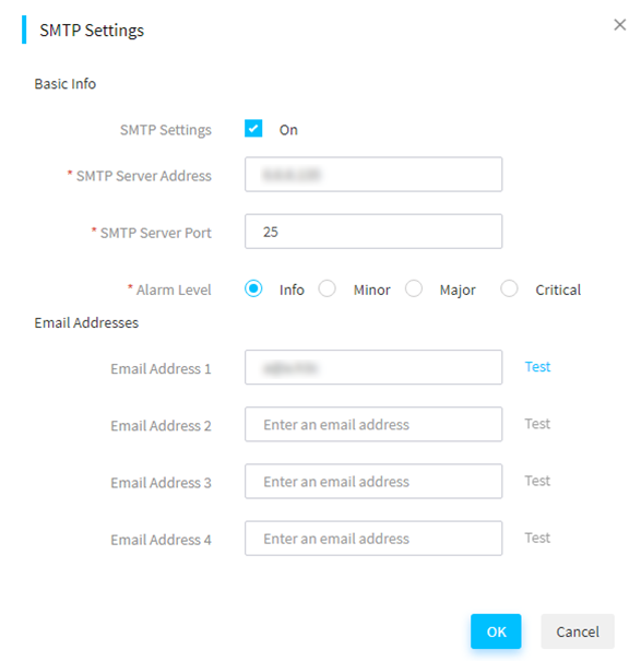
3. Click the SMTP Settings tab. In the dialog box that opens, perform the following steps:
a. Enter the SMTP settings, click the SMTP Settings tab.
b. Enter On for SMTP Settings.
c. Enter the port number of the SMTP server. The default port number is 25.
d. Select whether to enable Anonymous Email. If this feature is not enabled, you must specify the encryption protocol, sender username, and sender password.
e. Select the alarm level.
f. To customize the IP address, HDM host name, alarm level, or alarm event description in the email subject, enter the ${ip}, ${HDM_HostName}, ${level}, or ${event} field. If you do not enter an email subject, the default email subject will be used.
g. Add the email addresses of alert recipients.
h. In the Additional Info field, enter the additional information to append to each email to be sent.
i. Click OK.
j. (Optional.) To test whether a recipient can receive an alarm, click Test for the email address of the recipient.
Figure 86 Configure SMTP settings
4. Click the SMTP Settings tab. In the dialog box that opens, perform the following steps:
a. Select On for SMTP Settings.
b. Enter the IP address of the SMTP server.
c. Enter the port number of the SMTP server. The default port number is 25.
d. Select whether to enable Anonymous Email. If this feature is not enabled, you must specify the encryption protocol, sender username, and sender password.
e. Select the alarm level.
f. To customize the IP address, HDM host name, alarm level, or alarm event description in the email subject, enter the ${ip}, ${HDM_HostName}, ${level}, or ${event} field. If you do not enter an email subject, the default email subject will be used.
g. Add the email addresses of alert recipients.
Configure SNMP settings
About SNMP settings
Perform this task to add SNMP users and target hosts to receive SNMP traps (trap destinations) from the managed servers. UniSystem will receive SNMP traps that have a severity level equal to or higher than the specified level from the managed servers and then forward the traps to the target trap hosts.
Application scenarios
Users can monitor the operational status of servers via SNMP traps and detect abnormalities promptly.
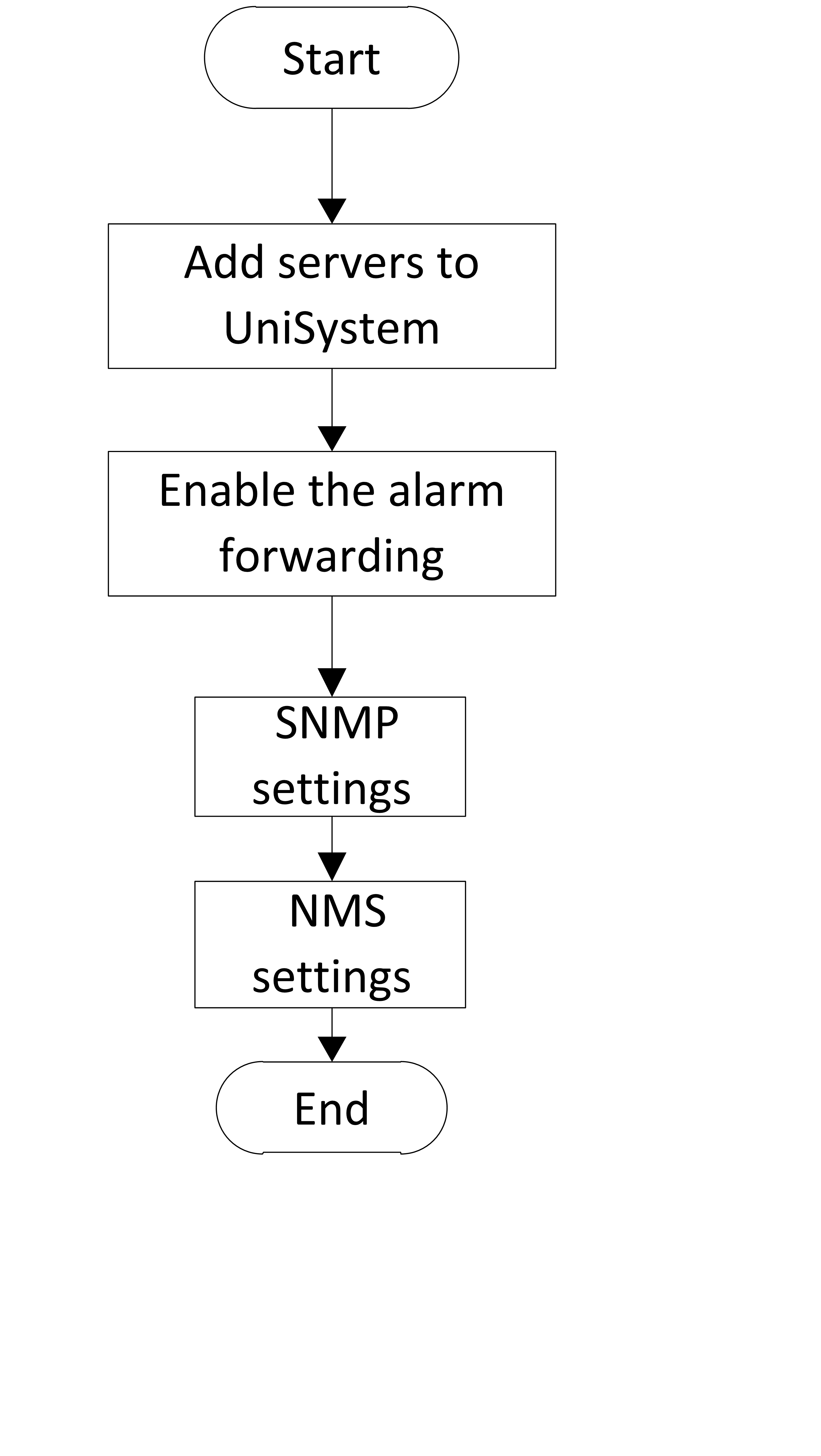
Configuration workflow
Figure 49 shows the SNMP configuration workflow.
Figure 87 SNMP configuration workflow
Prerequisites
· Obtain the NMS to receive trap information.
· Add servers to UniSystem.
Restrictions and guidelines
· The SNMP version and community name on both the Agent and NMS must match for the NMS to receive alerts from the Agent.
· NMS software configuration varies by vendor.
· The UniSystem server can only receive Trap information from managed servers when its monitoring settings are enabled.
· If HDM sets an alarm level, UniSystem SNMP filters and forwards alarms that meet or exceed this level.
· If severity levels of alarms to be sent are specified on both UniSystem and HDM, only alarms that match both the severity levels will be sent.
Procedure
1. In the navigation pane, select Menu > Monitor > Alarm Forwarding.
2. Click the SNMP Settings tab.
3. (Optional.) To send SNMPv3 traps, click Add SNMP User to add an SNMP user as follows:
a. Enter a username.
b. Select a security level.
c. Select an authentication protocol for the user.
d. Enter the authentication password for the user.
e. Click OK.
4. Click Add Trap Destination, and configure the trap destination as follows:
a. Enter the destination IP address.
b. Enter the destination port number. The default destination port number is 162.
c. Select an SNMP version.
d. Enter the community.
e. Select an output trap level.
5. Click OK.
6. (Optional.) To send a test alarm message to a trap destination, click Test in the Actions column of the trap destination.
Configure WeCom, SMS and voice notification
About WeCom, SMS and voice notification
Perform this task to configure WeCom, SMS and voice notification. With this feature enabled, the SNMP traps of managed servers will be sent through voice messages.
Application scenarios
Users can receive notifications about changes in the Trap information or health status of servers via WeCom, SMS and voice.
Configuration workflow
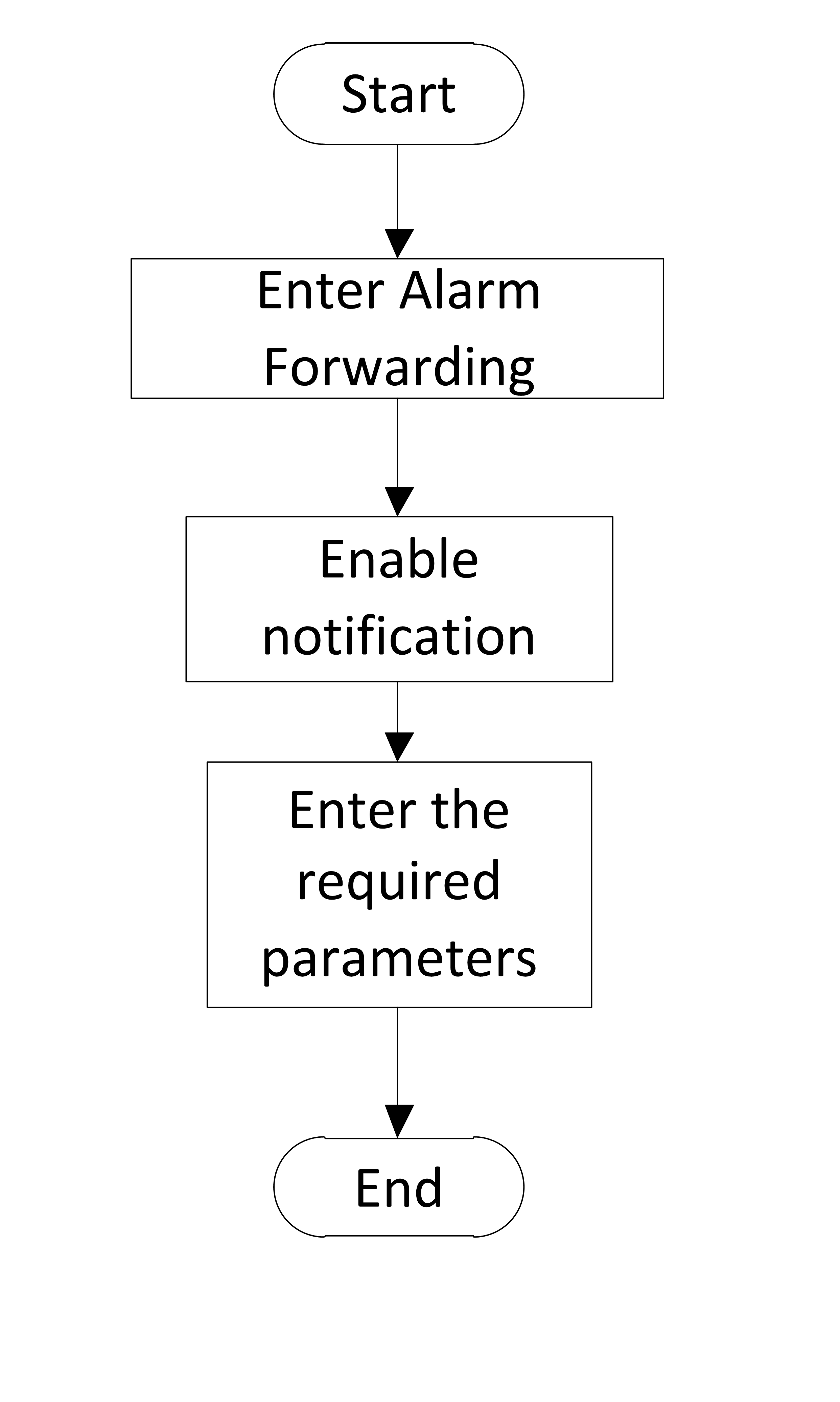
The WeCom. SMS and voice notification configuration flowchart is shown in Figure 50.
Figure 88 WeCom, SMS and voice notification configuration workflow
Prerequisites
· Only the WeCom administrator can obtain the WeCom parameters.
· Please configure DNS and proxy as required.
Restrictions and guidelines
Only Emay is supported in the current software version. For information about the SMS service content, contact Emay. For Emay, mainland China SMS belong to a different service from SMS provided in Hongkong, Macao and Taiwan, China, and other countries or regions. Do not mix the customer IDs of different services. For other functions, contact Emay customer service.
Procedures
Configure WeCom notification
1. In the navigation pane, select Menu > Monitor > Alarm Forwarding.
2. Click the WeCom Notification tab.
3. Enable WeCom notification, enter the required parameters, and click Save.
4. (Optional.) Click Test to test whether a notification can be sent to the specified WeCom application.
Configure SMS notification
1. In the navigation pane, select Menu > Monitor > Alarm Forwarding.
2. Click the SMS Notification tab.
3. Enable SMS notification and enter the required parameters.
4. Click Add Phone Number and enter phone numbers.
5. (Optional.) Click ![]() for
a phone number to test whether a SMS notification can be sent to the phone
number.
for
a phone number to test whether a SMS notification can be sent to the phone
number.
6. (Optional.) Click ![]() for a phone number to delete the phone number for receiving SMS
notifications.
for a phone number to delete the phone number for receiving SMS
notifications.
7. Click Save.
Configure voice notification
1. In the navigation pane, select Menu > Monitor > Alarm Forwarding.
2. Click the Voice Notification tab.
3. Enable voice notification and enter the required parameters.
4. Click Add Phone Number and enter phone numbers.
5. (Optional.) Click ![]() for
a phone number to test whether a voice notification can be sent to the phone
number.
for
a phone number to test whether a voice notification can be sent to the phone
number.
6. (Optional.) Click ![]() for
a phone number to delete the phone number for receiving voice notifications.
for
a phone number to delete the phone number for receiving voice notifications.
7. Click Save.
Configure tools
Configure PXE deployment
About PXE deployment
PXE operates in a Client/Server network model, where the PXE server supplies the OS image files. PXE deployment allows a PXE client to download the OS it requires over the network and then automatically boot and install the OS.
Application scenarios
Users can use this feature to perform bulk OS installations on servers.
Configuration workflow
The PXE configuration flowchart is shown in Figure 51.
Figure 89 PXE deployment configuration workflow
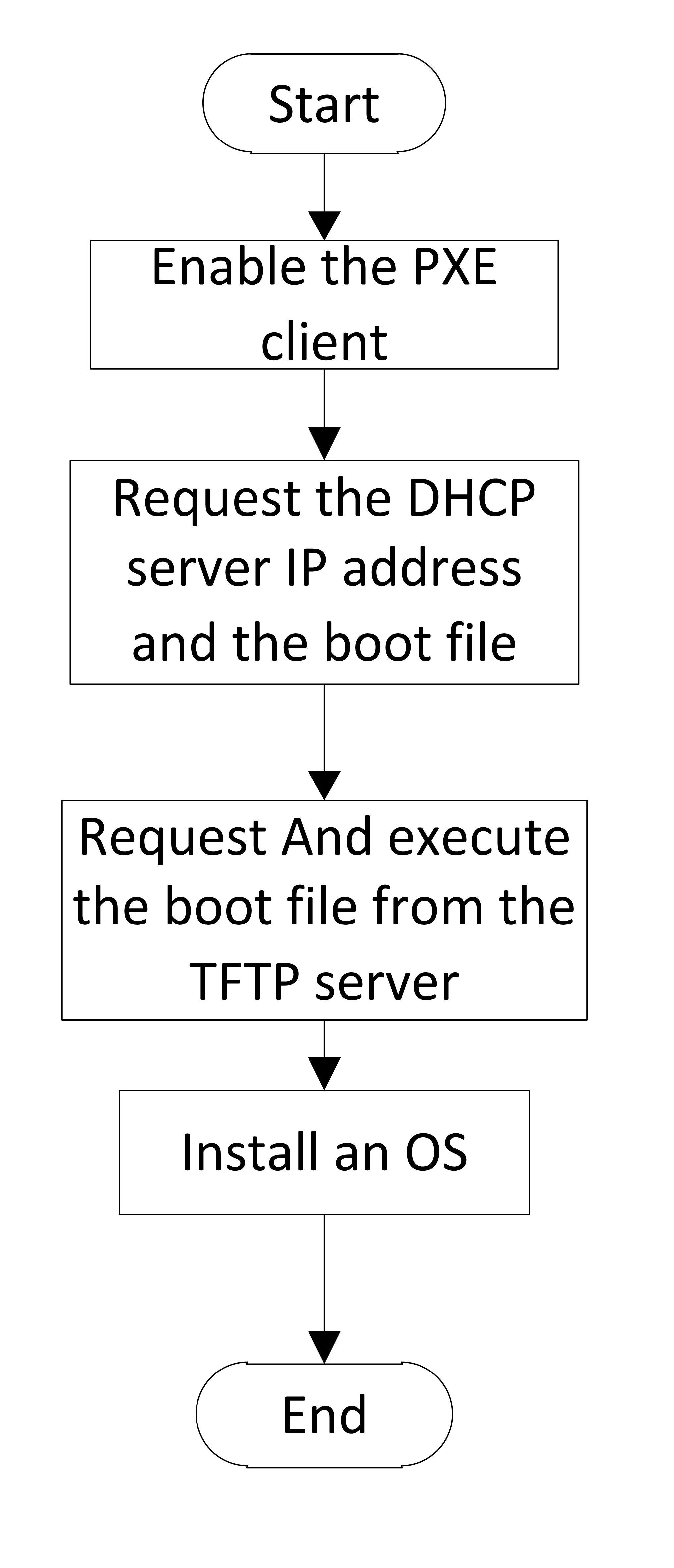
Restrictions and guidelines
· A PXE-capable Ethernet adapter is required on the PXE client.
· The PXE client obtains an IP address through the DHCP feature in PXE deployment.
· The IP range does not include a broadcast address.
· The IP addresses in the IP range do not conflict with existing IP addresses on the network.
· PXE deployment uses port numbers 67 and 69 as the DHCP service and the TFTP service, respectively. For PXE deployment to start successfully, make sure port numbers 67 and 69 are not used by other services.
· The DHCP feature in PXE deployment is exclusive with the DHCP server feature. You cannot configure the two features at the same time because port conflict will occur.
· When you install an OS to a blade server through PXE deployment, follow these restrictions and guidelines:
¡ If the iPXE boot loader is used, PXE deployment will fail for a server installed with a mezzanine card and with the legacy boot mode. In this case, use the PXELINUX or GRUB2 boot loader.
¡ The start IP address in the IP range must be on the same subnet as the IP address of network port vmng on the AE module.
¡ The IP range does not include the IP address of network port vmng on the AE module.
· IP addresses in the range of 192.250.0.0 through 192.250.255.255 are reserved for internal use. Do not include these IP addresses in the IP range.
Procedure
1. In the navigation pane, select Menu > Tools > PXE Deployment.
2. Click Configure Parameters, and configure PXE deployment parameters as follows:
a. Select a boot loader configuration mode.
b. Enter the DHCP start IP address and the DHCP-assigned IP address count.
During PXE deployment, the DHCP server will assign an IP address in this range to a server. After the OS installation, the server will use this IP address as the system IP address.
c. Select an image from the image list.
3. Click OK.
Table 11 Description of BootLoader configuration parameters
|
Item |
Description |
|
PXELINUX |
Derived from SysLinux, PXELINUX enables a client to boot from a network server. |
|
GRUB2 |
Also referred to GNU GRUB. GRUB2 is a multi-OS boot loader from the GNU project. GRUB2 allows a client to have multiple OSs simultaneously and boot from an expected OS. |
|
iPXE |
Provides enhanced PXE implementations. It is compatible with multiple protocols. As a best practice, use iPXE. |
Push and install software
About software push and installation
This module allows you to remotely install FIST SMS or general software to the OSs of the servers managed by UniSystem.
Application scenarios
This feature pushes the software installation package and installs script to the OS of a server and installs the software by executing the install script.
Configuration workflow
The software push and installation flowchart is shown in Figure 52.
Figure 90 Software push and installation workflow
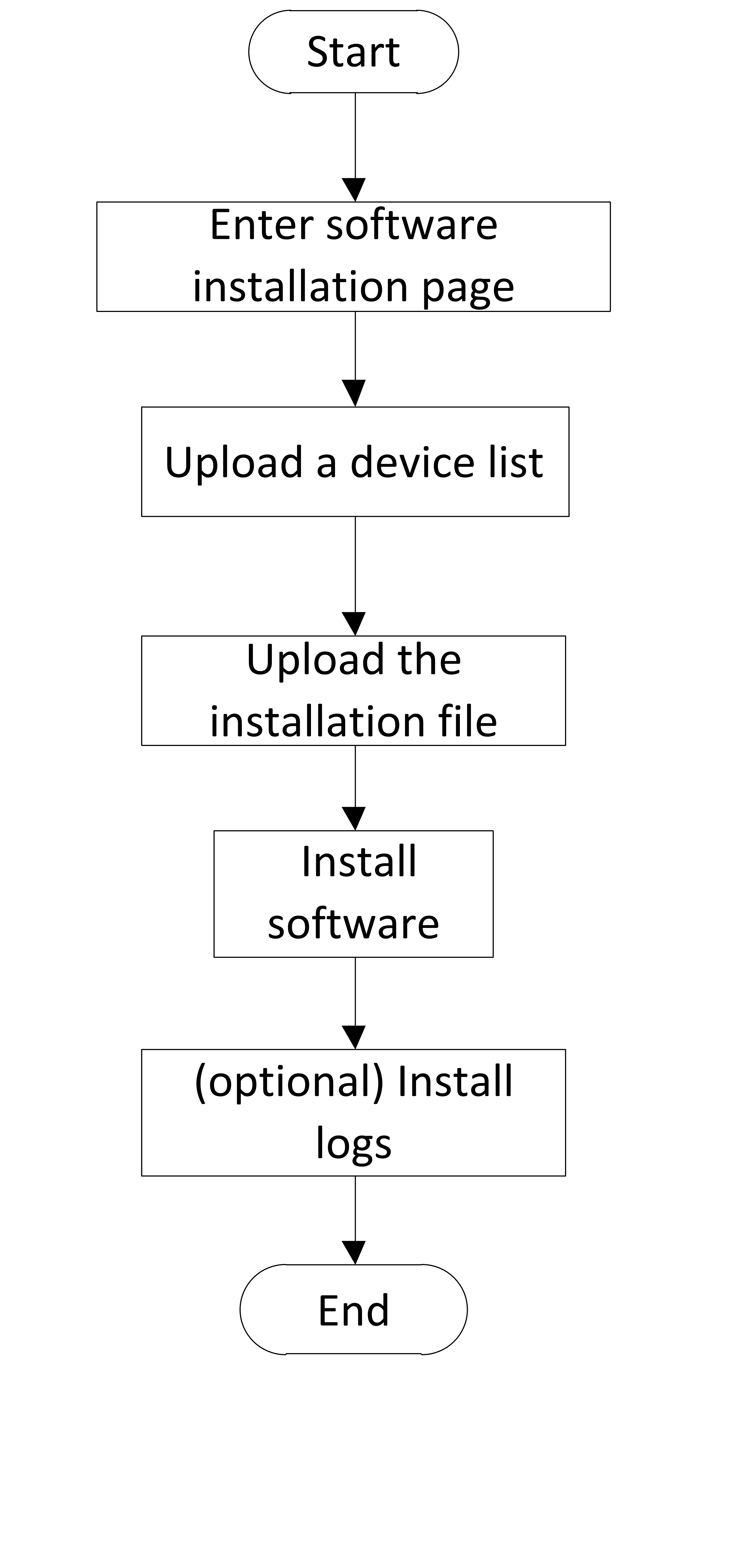
Prerequisites
Verify the winrm service status on a Windows server
1. Log in to the Windows system as an administrator and start PowerShell.
2. Execute the Get-Service winrm command to check the status of the winrm service.
¡ No actions are required if the service status is Running.
¡ Proceed to the next step if the service status is Stopped.
Figure 91 Check the winrm service status
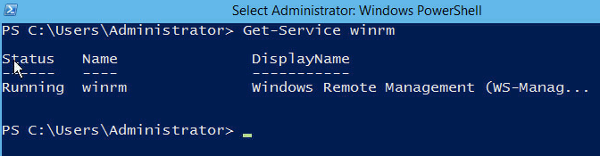
3. Execute the winrm quickconfig command to start the winrm service.
Figure 92 Start the winrm service
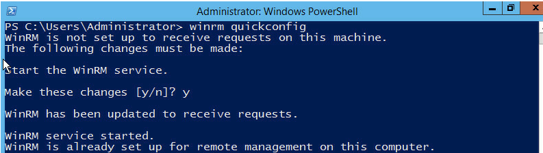
4. Execute the winrm set winrm/config/service '@{AllowUnencrypted="true"}' command to allow unencrypted transmission.
Figure 93 Allow unencrypted transmission
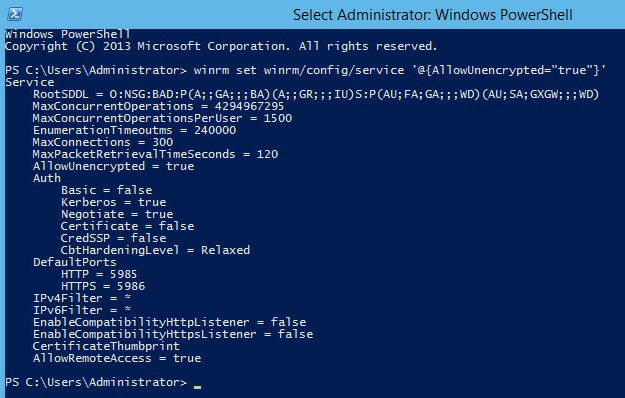
5. Execute the winrm set winrm/config/winrs '@{MaxMemoryPerShellMB="2024"}' command to set the maximum PowerShell memory size to a value greater than 1/16 of the server's physical memory.
Figure 94 Set the maximum PowerShell memory
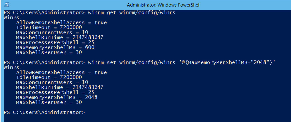
Verify the sshd service status on a Linux server
1. Log in to the Linux system as an administrator.
2. Install the sshd service and execute the service sshd start command to start the service. If the service has been installed, execute the service sshd status command to check the sshd service status.
¡ No actions are required if the service status is active.
¡ Proceed to the next step if the service status is inactive.
Figure 95 Check the sshd service status
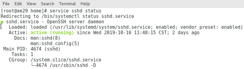
3. Execute the service sshd start command to start the sshd service. If the system prompts that sshd is not installed.
To install FIST SMS, follow these guidelines:
· Install OpenJDK 1.8 (64-bit) on the server to be installed with FIST SMS. As from FIST SMS-1.37, if you install FIST SMS to a Window operating system, you do not need to configure the OpenJDK software in advance.
· To start FIST SMS successfully, use port 12580 only for FIST SMS.
· Verify that the winrm service is correctly configured on a Windows server or the sshd service has started on a Linux server.
To install general software, follow these guidelines:
· Prepare the software installation package and install script in advance and package them together into an installation file in the .tar.gz format.
· You might fail to install general software because of the following reasons:
¡ The running time of the install script exceeds the upper limit. The running time upper limit of the install script is 20 seconds in the Windows system and 20 minutes in the Linux system.
¡ The install script contains interactive statements, such as the pause statement.
· The extension of the install script varies by OS type.
¡ In the Windows operating system, the install script must be named as install.bat.
¡ In the Linux operating system, the install script must be named as install.sh.
· Verify that the winrm service is correctly configured on a Windows server or the sshd service has started on a Linux server.
Restrictions and guidelines
The FIST SMS installation feature is available in version 2.00.16 and later versions.
The general software installation feature is available in version 2.00.33 and later.
This feature supports only FIST SMS-1.03.08 and later versions.
To avoid FIST SMS installation failure, do not make any changes to the installation package.
Procedure
1. In the navigation pane, select Menu > Tools > Push and Install Software.
2. Select an installation file type.
3. To upload a device list, perform the following steps:
a. (Optional.) Click Download Template under Device List File to download the device list template, and edit the devices in the device list template.
b. Click … in the Device List File field.
c. In the dialog box that opens, click Browse, select a device list file, and then click OK.
d. Click Upload. The Device List area displays the list of devices to which you can install FIST SMS or general software.
4. Click Next.
5. To upload a FIST SMS or general software installation file or FIST SMS driver file, perform the following tasks:
a. Click … in the FIST SMS Installation File, General Software Installation File, or FIST SMS Driver File field.
b. In the dialogue box that opens, click Browse, select the target file, and then click OK.
6. Click Upload. The system displays the name of the uploaded file.
7. Click Install. The system starts to install FIST SMS or general software on the servers in the device list. It will take a long time, wait for the process to finish.
After you install general software successfully, you can view the information in the Logs column. To view detailed logs, you can select devices in the device list and then click Download.
8. Click Finish.
Configure system settings
Configure a cluster
About cluster configuration
This module allows you to create or manage a cluster of AE modules to implement high availability.
Application scenarios
When deploying UniSystem in the AE module, it supports the creation of a 1+1 primary-secondary cluster. When the primary node fails, UniSystem will switch to run on the secondary node, which avoids service interruption caused by the failure of the primary AE module.
Configuration workflow
Figure 58 shows the cluster configuration flowchart .
Figure 96 Cluster configuration workflow
Prerequisites
Cluster creation requires data synchronization. For correct data synchronization, make sure the time difference between the primary and secondary nodes is shorter than 10 seconds.
If a cluster is created, make sure the following conditions are met:
· Make sure the primary and secondary nodes can reach each other. As a best practice, assign static IP addresses to ports for the primary and secondary nodes to communicate with each other and make sure the ports have the same subnet mask.
· Make sure the primary and secondary nodes each have a unique host name for UniSystem access. Do not set the host name to localhost or a string of all digits.
· Do not configure multiple IP addresses on the same subnet for each network port.
Restrictions and guidelines
· The secondary UniSystem node in the cluster will be stopped during cluster creation.
· During cluster creation, do not power off the AE modules or disconnect the network. Data synchronization will take a long time, please wait till the whole progress finishes.
· During cluster creation, do not perform any other operations on UniSystem of the primary node.
· After the cluster is created, do not edit the host name, network, or system settings of UniSystem.
· UniSystem cannot be reverted from cluster mode to standalone mode.
· Cluster creation failure will cause the unavailability of UniSystem. Please try again to create the cluster.
Procedure
1. In the navigation pane, select Menu > System > Cluster.
2. Click the Create Cluster link.
3. On the page that opens, configure the following parameters of the cluster to be created. The specific parameter descriptions are shown in Table 12.
Table 12 Description of a cluster configuration parameters
|
Item |
Description |
|
Secondary Node Address |
IP address used by the secondary node to communicate with the primary node. As a best practice, use the IP address of network port vmng.om or the 10-GE network port of the secondary AE module. |
|
UniSystem Virtual IP Address |
Virtual IP address for users to access UniSystem after the cluster is created. |
|
iSCSI Virtual IP Address |
IP address used to configure the iSCSI service. Make sure the entered iSCSI virtual IP address is on the same network segment as an IP address of the 10-GE network port on the primary AE module. |
4. Click OK. You can see the progress of the creation from the progress bar. To view detailed information about the cluster creation, click View Log.
5. UniSystem will automatically restart after the cluster is successfully created. Log in to UniSystem by using the virtual IP address of UniSystem.
6. View information about the primary and secondary nodes on the Cluster page.
7. Click the Edit
icon ![]() next to the secondary node. In the dialog box that opens, enter the
IP address of the node to replace the current secondary node. Then, click OK. You can see
the progress of the replacement from the progress bar.
next to the secondary node. In the dialog box that opens, enter the
IP address of the node to replace the current secondary node. Then, click OK. You can see
the progress of the replacement from the progress bar.
Manage LDAP
About LDAP management
LDAP, as a unified authentication solution can provide quick access to LDAP users on the server.
Application scenarios
You can add LDAP servers to UniSystem and then add LDAP user groups on the LDAP servers to UniSystem. Member users in the LDAP user groups can then log in to UniSystem directly with their credentials stored in the LDAP server.
Configuration workflow
Figure 59 shows the LDAP management flowchart.
Figure 97 LDAP management workflow
Prerequisites
The LDAP server needs to be configured in advance.
Procedures
View LDAP server information and testing connectivity to a server
1. In the navigation pane, select Menu > System > LDAP Management.
The LDAP Settings tab displays information about the LDAP servers configured in the system, each on a separate card.
Figure 98 LDAP settings tab
2. (Optional.) To test connectivity to an LDAP
server, click ![]() in the top right corner of the LDAP server card. For an LDAP server
that uses the User Account directory binding type, you will be prompted
to enter the username and password for connectivity test.
in the top right corner of the LDAP server card. For an LDAP server
that uses the User Account directory binding type, you will be prompted
to enter the username and password for connectivity test.
Add an LDAP server
Perform this task to add an LDAP server to UniSystem. UniSystem supports a maximum of five LDAP servers.
Procedure
1. In the navigation pane, select Menu > System > LDAP Management.
2. Click Add LDAP Server.
3. In the Add LDAP Server dialog box that opens, configure the LDAP server parameters.
Figure 99 Add LDAP server dialog box
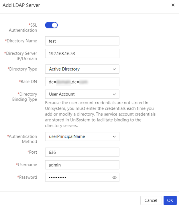
4. Click OK.
