- Table of Contents
- Related Documents
-
| Title | Size | Download |
|---|---|---|
| 01-Installation Guide | 9.68 MB |
Examining the installation site
Installing the switch in a 19-inch rack
Rack-mounting procedures at a glance
Mounting brackets, chassis rails, and grounding cable installation positions
Attaching the mounting brackets and chassis rails to the chassis
Connecting the grounding cable to the chassis
Attaching the slide rails to the rack
Mounting the switch in the rack
Installing/removing power modules
Installing/removing expansion modules
Installing an expansion module
3 Accessing the switch for the first time
Connecting the switch to a configuration terminal
Connecting a DB9-to-RJ45 console cable
Connecting a USB-to-RJ45 console cable
Connecting the mini USB console cable
Planning IRF fabric size and the installation site
Identifying the master switch and planning IRF member IDs
Planning IRF topology and connections
Identifying physical IRF ports on the member switches
Configuring basic IRF settings
Connecting the physical IRF ports
Accessing the IRF fabric to verify the configuration
Planning for setting up an M-LAG system
Determining device installation locations
Reserving physical ports for M-LAG connection
Planning the cable connection scheme
Configuring the M-LAG system settings
Connecting the M-LAG member switches
6 Maintenance and troubleshooting
Configuration terminal display problems
1 Preparing for installation
H3C S6850 & S9850 Ethernet switch series includes the following models:
|
Product series |
Product model |
Product code |
|
H3C S6850 series |
S6850-56HF |
LS-6850-56HF LS-6850-56HF-H1 LS-6850-56HF-H3 |
|
S6850-56HF-SAN |
LS-6850-56HF-SAN |
|
|
S6850-2C |
LS-6850-2C LS-6850-2C-H1 |
|
|
H3C S9850 series |
S9850-4C |
LS-9850-4C LS-9850-4C-H1 |
|
S9850-32H |
LS-9850-32H-A LS-9850-32H-H1 |
Safety recommendations
To avoid any equipment damage or bodily injury caused by incorrect use, read the following safety recommendations before installation. Note that the recommendations do not cover every possible hazardous condition.
· Before cleaning the switch, remove all power cords from the switch. Do not clean the switch with wet cloth or liquid.
· Do not place the switch near water or in a damp environment. Prevent water or moisture from entering the switch chassis.
· Do not place the switch on an unstable case or desk. The switch might be severely damaged in case of a fall.
· Ensure good ventilation of the equipment room and keep the air inlet and outlet vents of the switch free of obstruction.
· Connect the yellow-green protection grounding cable before power-on.
· Make sure the operating voltage is in the required range.
· To avoid electrical shocks, do not open the chassis while the switch is operating or when the switch is just powered off.
· When replacing field replaceable units (FRUs), including power modules and fan trays, wear an ESD wrist strap to avoid damaging the units.
Examining the installation site
The switch must be used indoors.
Mount your switch in a rack and verify the following items:
· Adequate clearance is reserved at the air inlet and outlet vents for ventilation.
· The rack has a good ventilation system.
· Identify the hot aisle and cold aisle at the installation site, and make sure ambient air flows into the switch from the cold aisle and exhausts to the hot aisle.
· Identify the airflow designs of neighboring devices, and prevent hot air flowing out of the neighboring devices from entering the top device.
· The rack is sturdy enough to support the switch and its accessories.
· The rack is reliably grounded.
To ensure correct operation and long service life of your switch, install it in an environment that meets the requirements described in the following subsections.
Temperature/humidity
Maintain appropriate temperature and humidity in the equipment room.
· Lasting high relative humidity can cause poor insulation, electricity leakage, mechanical property change of materials, and metal corrosion.
· Lasting low relative humidity can cause washer contraction and ESD and cause problems including loose mounting screws and circuit failure.
· High temperature can accelerate the aging of insulation materials and significantly lower the reliability and lifespan of the switch.
For the temperature and humidity requirements for the switch, see H3C S6850 & S9850 Switch Series Hardware Information and Specifications.
Cleanliness
Dust buildup on the chassis might cause electrostatic adsorption and dust corrosion, resulting in poor contact of metal connectors and contact points. This might shorten the device's lifetime and even cause device failure in the worst case. Table1-1 describes the switch requirement for cleanliness.
Table1-1 Switch requirement for cleanliness
|
Substance |
Particle diameter |
Concentration limit |
|
Dust particles |
≥ 0.5 µm |
≤ 1.8 × 10⁷ particles/m3 |
To maintain cleanliness in the equipment room, follow these guidelines:
· Keep the equipment room away from pollution sources. Do not smoke, eat, or drink in the equipment room.
· Use double-layer glass in windows and seal doors and windows with dust-proof rubber strips. Use screen doors and window screens for doors and windows open to the outside and make sure the external windows are air tight.
· Use dustproof materials for floors, walls, and ceilings and use wallpaper or matt paint that does not produce powders.
· Clean the equipment room regularly and clean the air filters of the rack each month.
· Wear ESD clothing and shoe covers before entering the equipment room, keep the ESD clothing and shoe covers clean, and change them frequently.
Corrosive gas limit
Corrosive gases can accelerate corrosion and aging of metal components. Make sure the corrosive gases do not exceed the concentration limits as shown in Table1-2.
Table1-2 Corrosive gas concentration limits
|
Gas |
Average concentration (mg/m3) |
Maximum concentration (mg/m3) |
|
SO2 |
0.3 |
1.0 |
|
H2S |
0.1 |
0.5 |
|
Cl2 |
0.1 |
0.3 |
|
HCI |
0.1 |
0.5 |
|
HF |
0.01 |
0.03 |
|
NH3 |
1.0 |
3.0 |
|
O3 |
0.05 |
0.1 |
|
NOX |
0.5 |
1.0 |
|
|
CAUTION: As a best practice, control the corrosive gas concentrations in the equipment room at their average values. Make sure the corrosive gas concentrations do not exceed 30 minutes per day at their maximum values. |
To control corrosive gases, use the following guidelines:
· As a best practice, do not build the equipment room in a place with a high concentration of corrosive gases.
· Make sure the equipment room is not connected to sewer, vertical shaft, or septic tank pipelines and keep it far away from these pipelines. The air inlet of the equipment room must be away from such pollution sources.
· Use environmentally friendly materials to decorate the equipment room. Avoid using organic materials that contains harmful gases, such as sulfur or chlorine-containing insulation cottons, rubber mats, sound-proof cottons, and avoid using plasterboards with high sulfur concentration.
· Place fuel (diesel or gasoline) engines separately. Do not place them in the same equipment room with the device. Make sure the exhausted air of the engines will not flow into the equipment room or towards the air inlet of the air conditioners.
· Place batteries separately. Do not place them in the same room with the device.
· Employ a professional company to monitor and control corrosive gases in the equipment room regularly.
EMI
All electromagnetic interference (EMI) sources, from outside or inside of the switch and application system, adversely affect the switch in the following ways:
· A conduction pattern of capacitance coupling.
· Inductance coupling.
· Electromagnetic wave radiation.
· Common impedance (including the grounding system) coupling.
To prevent EMI, use the following guidelines:
· If AC power is used, use a single-phase three-wire power receptacle with protection earth (PE) to filter interference from the power grid.
· Keep the switch far away from radio transmitting stations, radar stations, and high-frequency devices.
· Use electromagnetic shielding, for example, shielded interface cables, when necessary.
· To prevent signal ports from getting damaged by overvoltage or overcurrent caused by lightning strikes, route interface cables only indoors.
Laser safety
|
|
WARNING! · The switch is a Class 1M laser device. · Disconnected optical fibers or transceiver modules might emit invisible laser light. Do not stare into beams or view directly with optical instruments when the switch is operating. |
Installation tools
No installation tools are provided with the switch. Prepare the following tools yourself:
· Phillips screwdriver.
· ESD wrist strap.
· Marker.
2 Installing the switch
|
|
CAUTION: Keep the tamper-proof seal on a mounting screw on the chassis cover intact, and if you want to open the chassis, contact H3C for permission. Otherwise, H3C shall not be liable for any consequence caused thereby. |
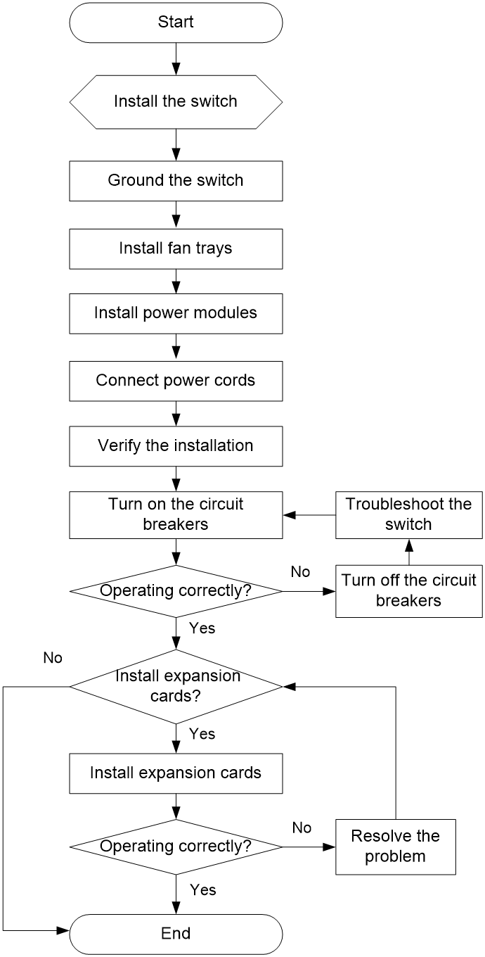
Figure2-1 Hardware installation flow
Installing the switch in a 19-inch rack
Rack-mounting procedures at a glance
Figure2-2 Rack-mounting procedure

|
|
NOTE: If a rack shelf is available, you can put the switch on the rack shelf and slide the switch to a position so that the mounting brackets make close contact with the front rack posts. Then use screws to secure the mounting brackets to the rack. |
Rack-mounting requirements
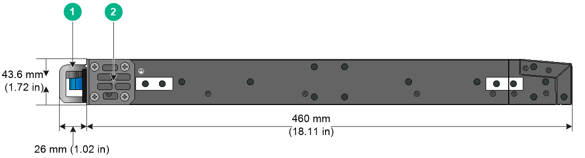
Figure2-3 LS-6850-56HF/LS-6850-56HF-H1/S6850-56HF-SAN chassis dimensions (mounting brackets installed at the port side, left-side view)

|
(1) Power module handle |
(2) Mounting bracket |
Figure2-4 LS-6850-56HF/LS-6850-56HF-H1/S6850-56HF-SAN chassis dimensions (mounting brackets installed at the power module side, left-side view)
|
(1) Power module handle |
(2) Mounting bracket |
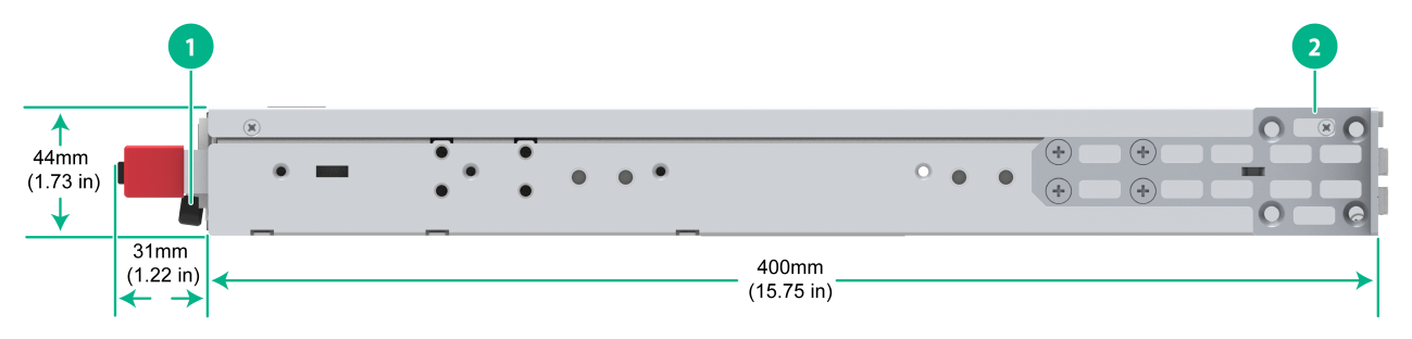
Figure2-5 LS-6850-56HF-H3 chassis dimensions (mounting brackets installed at the port side, left-side view)
|
(1) Power module handle |
(2) Mounting bracket |
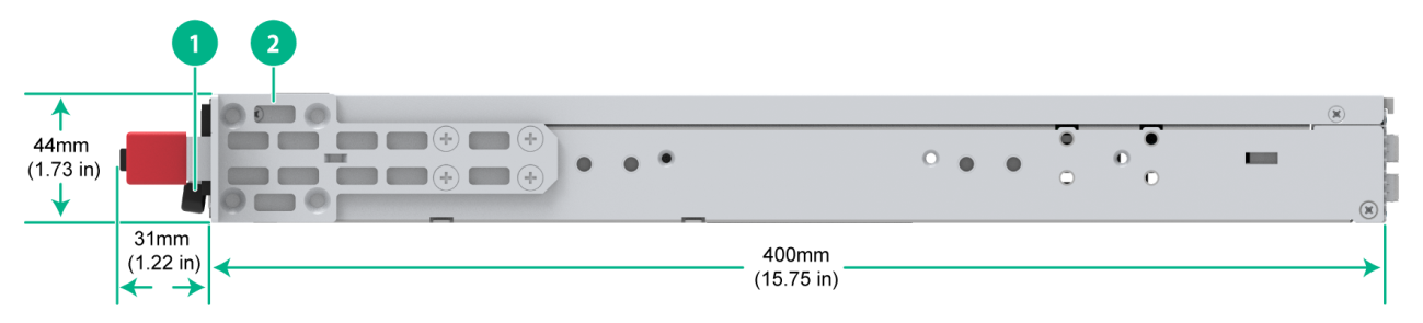
Figure2-6 LS-6850-56HF-H3 chassis dimensions (mounting brackets installed at the power module side, left-side view)
|
(1) Power module handle |
(2) Mounting bracket |
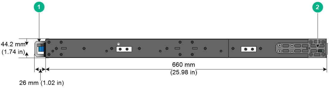
Figure2-7 S6850-2C chassis dimensions (mounting brackets installed at the port side, left-side view)
|
(1) Power module handle |
(2) Mounting bracket |
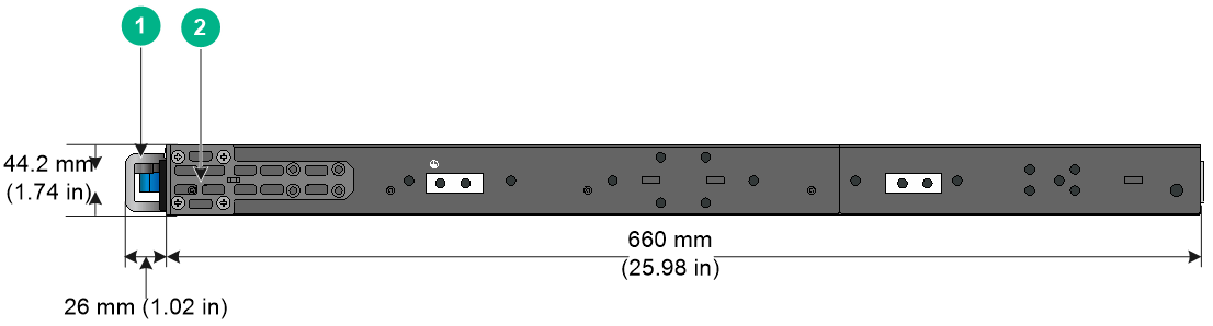
Figure2-8 S6850-2C chassis dimensions (mounting brackets installed at the power module side, left-side view)
|
(1) Power module handle |
(2) Mounting bracket |
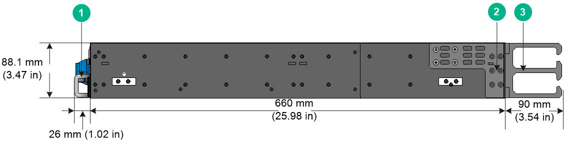
Figure2-9 S9850-4C chassis dimensions (mounting brackets installed at the port side, left-side view)
|
(1) Power module handle |
(2) Mounting bracket |
|
(3) Cable management bracket |
|
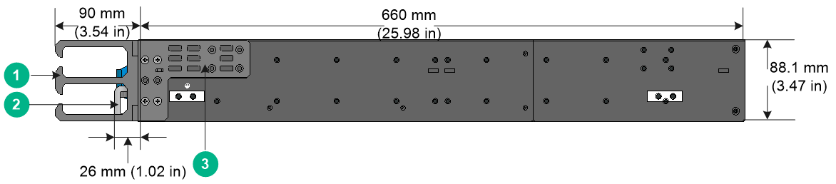
Figure2-10 S9850-4C chassis dimensions (mounting brackets installed at the power module side, left-side view)
|
(1) Cable management bracket |
(2) Power module handle |
|
(3) Mounting bracket |
|
Figure2-11 S9850-32H chassis dimensions (mounting brackets installed at the port side, left-side view)
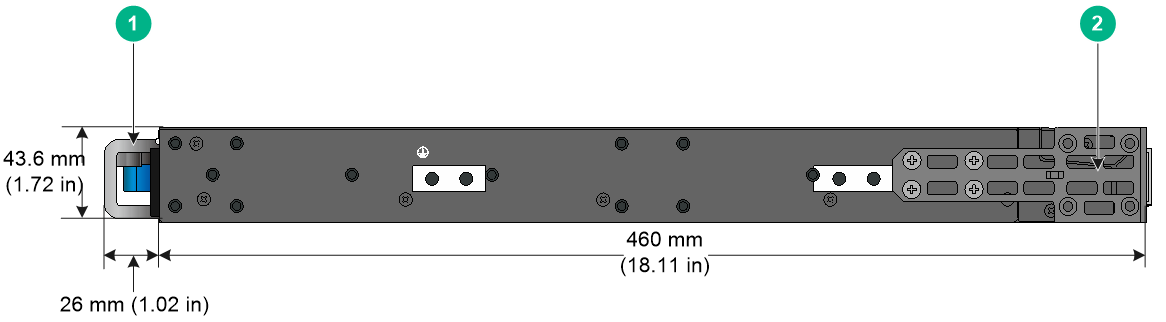
|
(1) Power module handle |
(2) Mounting bracket |
Figure2-12 S9850-32H chassis dimensions (mounting brackets installed at the power module side, left-side view)
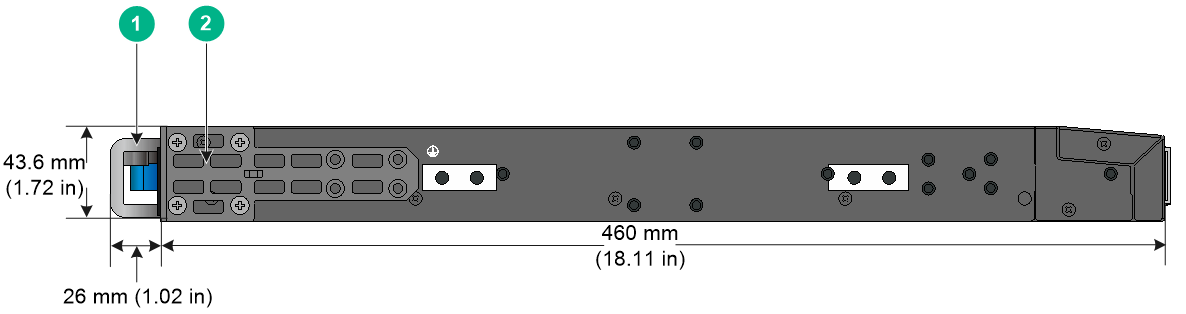
|
(1) Power module handle |
(2) Mounting bracket |
Table2-2 Distance requirements between the front and rear rack posts
|
Switch model |
Installation method |
Chassis dimensions |
Distance between the front and rear rack posts |
Rack requirements |
|
LS-6850-56HF LS-6850-56HF-H1 S6850-56HF-SAN |
Mounting brackets and long slide rails (provided) |
· Height—43.6 mm (1.72 in)/1 RU · Width—440 mm (17.32 in) · Depth—486 mm (19.13 in) ¡ 460 mm (18.11 in) for the chassis ¡ 26 mm (1.02 in) for the power module/fan tray handles |
692 to 853 mm (27.24 to 33.58 in) |
· A minimum of 800 mm (31.50 in) in depth (recommended) · A minimum of 130 mm (5.12 in) between the front rack post and the front door. · A minimum of 550 mm (21.65 in) between the front rack post and the rear door. |
|
Mounting brackets and super-short slide rails (optional, chassis rails not reaching out of the chassis) |
401 to 565 mm (15.79 to 22.24 in) |
|||
|
Mounting brackets and super-short slide rails (optional, chassis rails reaching out of the chassis) |
499 to 692 mm (19.65 to 27.24 in) |
|||
|
LS-6850-56HF-H3 |
Mounting brackets and long slide rails (provided) |
· Height—44 mm (1.73 in)/1 RU · Width—440 mm (17.32 in) · Depth—431 mm (16.97 in) ¡ 400 mm (15.75 in) for the chassis ¡ 31 mm (1.22 in) for the fan tray handle |
634 to 793 mm (24.96 to 31.22 in, mounting brackets installed at the port side) |
· A minimum of 800 mm (31.50 in) in depth (recommended) · A minimum of 130 mm (5.12 in) between the front rack post and the front door. · A minimum of 550 mm (21.65 in) between the front rack post and the rear door. |
|
634 to 728 mm (24.96 to 28.66 in, mounting brackets installed at the power module side) |
||||
|
Mounting brackets and super-short slide rails (optional, chassis rails not reaching out of the chassis) |
397 to 505 mm (15.63 to 19.88 in, mounting brackets installed at the port side) |
|||
|
343 to 440 mm (13.50 to 17.32 in, mounting brackets installed at the power module side) |
||||
|
Mounting brackets and super-short slide rails (optional, chassis rails reaching out of the chassis) |
504 to 612 mm (19.84 to 24.09 in, mounting brackets installed at the port side) |
|||
|
439 to 547 mm (17.28 to 21.54 in, mounting brackets installed at the power module side) |
||||
|
S6850-2C |
Mounting brackets at the port side |
· Height—44.2 mm (1.74 in)/1 RU · Width—440 mm (17.32 in) · Depth—686 mm (27.01 in) ¡ 660 mm (25.98 in) for the chassis ¡ 26 mm (1.02 in) for the power module/fan tray handles |
519 to 768 mm (20.43 to 30.24 in) |
· A minimum of 1000 mm (39.37 in) in depth (recommended) · A minimum of 130 mm (5.12 in) between the front rack post and the front door. · A minimum of 750 mm (29.53 in) between the front rack post and the rear door. |
|
Mounting brackets at the power module side |
||||
|
S9850-4C |
Mounting brackets at the port side |
· Height—88.1 mm (3.47 in)/2 RU · Width—440 mm (17.32 in) · Depth—776 mm (33.55 in) ¡ 660 mm (25.98 in) for the chassis ¡ 26 mm (1.02 in) for the power module/fan tray handles ¡ 90 mm (3.54) for the mounting brackets |
518 to 923 mm (20.39 to 36.34 in) |
· A minimum of 1000 mm (39.37 in) in depth (recommended) · A minimum of 130 mm (5.12 in) between the front rack post and the front door. · A minimum of 750 mm (29.53 in) between the front rack post and the rear door. |
|
Mounting brackets at the power module side |
· Height—88.1 mm (3.47 in)/2 RU · Width—440 mm (17.32 in) · Depth—750 mm (29.53 in) ¡ 660 mm (25.98 in) for the chassis ¡ 90 mm (3.54) for the mounting brackets |
518 to 858 mm (20.39 to 33.78 in) |
||
|
S9850-32H |
Mounting brackets and long slide rails (provided) |
· Height—43.6 mm (1.72 in)/1 RU · Width—440 mm (17.32 in) · Depth—486 mm (19.13 in) ¡ 460 mm (18.11 in) for the chassis ¡ 26 mm (1.02 in) for the power module/fan tray handles |
621 to 853 mm (24.45 to 33.58 in) |
· A minimum of 1000 mm (39.37 in) in depth (recommended) · A minimum of 130 mm (5.12 in) between the front rack post and the front door. · A minimum of 550 mm (21.65 in) between the front rack post and the rear door. |
|
Mounting brackets and short slide rails (provided) |
401 to 633 mm (15.79 to 24.92 in) |
Installation accessories
Table2-3 Installation accessories
|
Switch model |
Mounting brackets (provided) |
Cable management brackets |
Rack mounting rail kit |
|
S6850-56HF S6850-56HF-SAN |
1U high, one pair. See Figure2-13. The mounting bracket with a round hole in the narrow flange supports hanging a fixed asset tag. |
N/A |
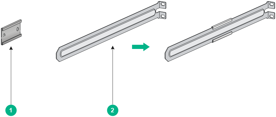
1U high, including one pair of long slide rails and one pair of chassis rails (provided). See Figure2-16. |
|
1U high, including one pair of super-short slide rails and one pair of chassis rails (optional). See Figure2-18. |
|||
|
S6850-2C |
1U high, one pair. See Figure2-13. The mounting bracket with a round hole in the narrow flange supports hanging a fixed asset tag. |
N/A |
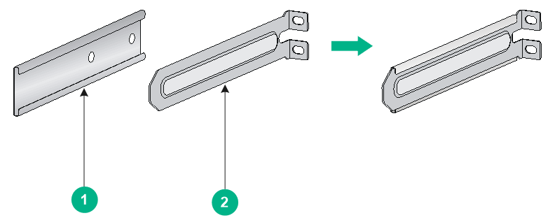
1U high, including one pair of short slide rails and one pair of chassis rails (provided). See Figure2-17. |
|
S9850-4C |
2U high, one pair. See Figure2-14. |
One pair (provided). See Figure2-14. |
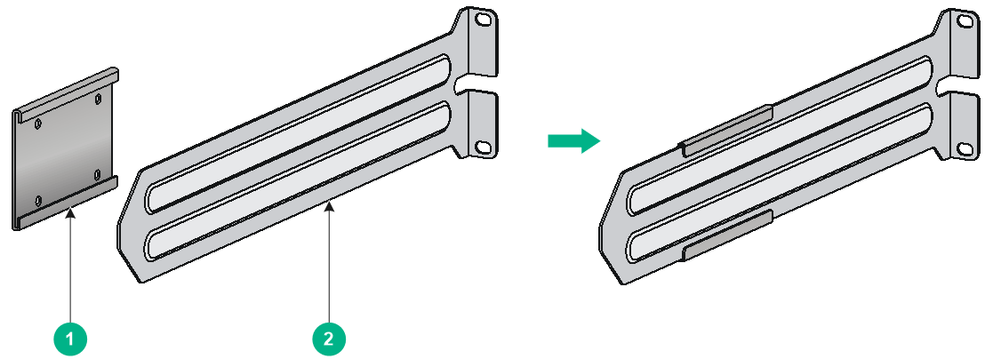
2U high, including one pair of slide rails and one pair of chassis rails (provided). See Figure2-19. |
|
S9850-32H |
1U high, one pair. See Figure2-15. The mounting bracket with a round hole in the narrow flange supports hanging a fixed asset tag. |
N/A |
1U high, including one pair of long slide rails and one pair of chassis rails (provided). See Figure2-16. |
|
1U high, including one pair of short slide rails and one pair of chassis rails (optional). See Figure2-17. |
Figure2-13 Mounting brackets provided with the S6850-56HF, S6850-56HF-SAN, and S6850-2C switches
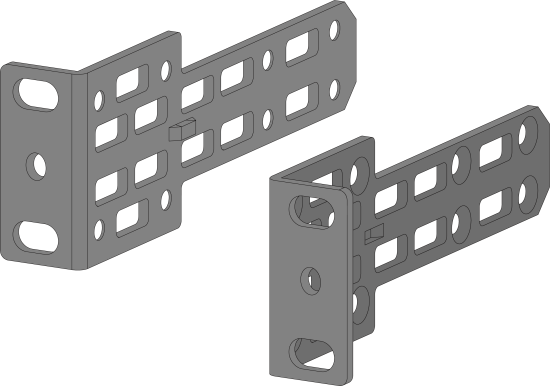
Figure2-14 Mounting brackets provided with the S9850-4C switch
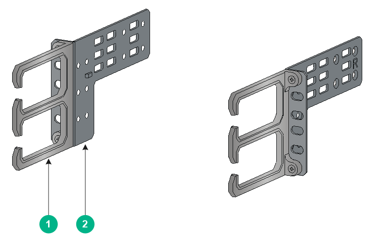
|
(1) Cable management bracket |
(2) Mounting bracket |
Figure2-15 Mounting brackets provided with the S9850-32H switch
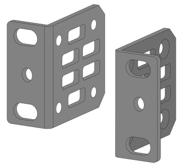
Figure2-16 1U long slide rail and chassis rail
|
(1) Chassis rail |
(2) Long slide rail |
Figure2-17 1U short slide rail and chassis rail

Figure2-18 1U super-short slide rail and chassis rail
|
(1) Chassis rail |
(2) Super-short slide rail |
Figure2-19 2U slide rail and chassis rail
|
(1) Chassis rail |
(2) Slide rail |
Mounting brackets, chassis rails, and grounding cable installation positions
The switch has one mounting position near the network ports and one mounting position near the power modules for mounting brackets.
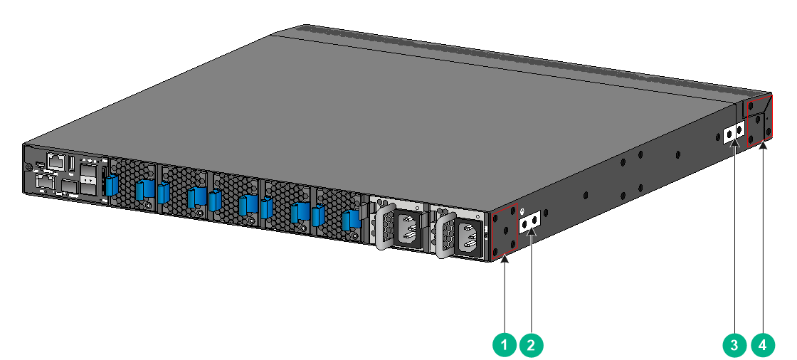
The LS-6850-56HF, LS-6850-56HF-H1, and S6850-56HF-SAN switches each provide two grounding points: primary grounding point (with a grounding sign) and auxiliary grounding point, as shown in Figure2-20.
The LS-6850-56HF-H3 switch provides one grounding point on the rear panel and two grounding points on the side panel, as shown in Figure2-21. As a best practice, use the grounding point on the rear panel and do not use the grounding points on the side panel.
The S6850-2C switch provides two grounding points: primary grounding point (with a grounding sign) and auxiliary grounding point, as shown in Figure2-22.
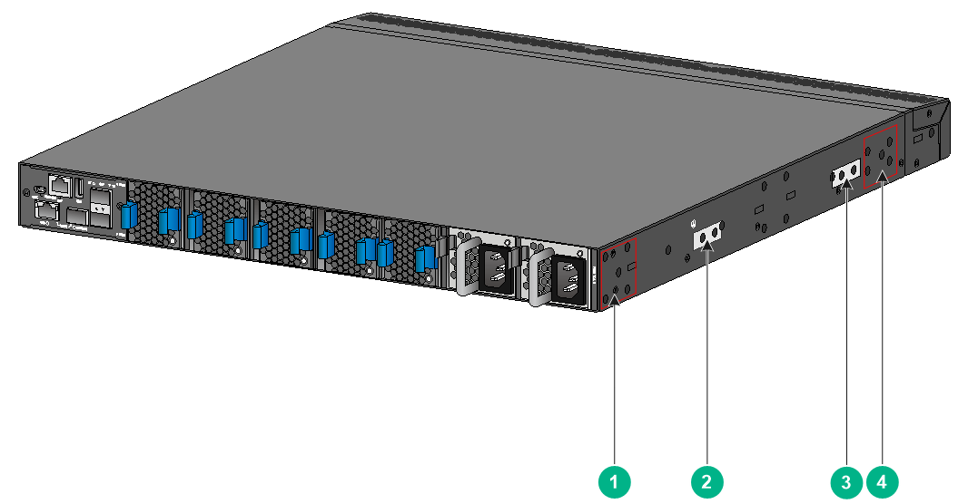
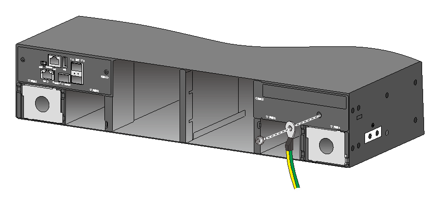
The S9850-4C switch provides three grounding points: primary grounding point (with a grounding sign), auxiliary grounding point 1, and auxiliary grounding point 2, as shown in Figure2-23.
The S9850-32H switch provides two grounding points: primary grounding point (with a grounding sign) and auxiliary grounding point, as shown in Figure2-24.
Select installation positions for the mounting brackets, chassis rails, and grounding cable as required.
Figure2-20 Mounting brackets and grounding cable installation positions on the LS-6850-56HF/LS-6850-56HF-H1/S6850-56HF-SAN switch
|
(1) Power module-side installation position for the mounting bracket |
|
|
(2) Primary grounding point |
(3) Auxiliary grounding point |
|
(4) Port-side installation position for the mounting bracket |
|
Figure2-21 Mounting brackets and grounding cable installation positions on the LS-6850-56HF-H3 switch
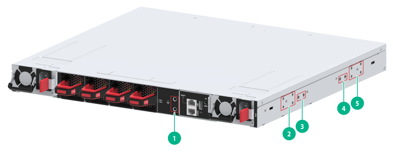
|
(1) Grounding point on the rear panel |
|
|
(2) Power module-side installation position for the mounting bracket |
|
|
(3) Grounding point 1 on the side panel |
(4) Grounding point 2 on the side panel |
|
(5) Port-side installation position for the mounting bracket |
|
|
|
CAUTION: As a best practice, use the grounding point on the rear panel and do not use the grounding points on the side panel. |
Figure2-22 Mounting brackets and grounding cable installation positions on the S6850-2C switch
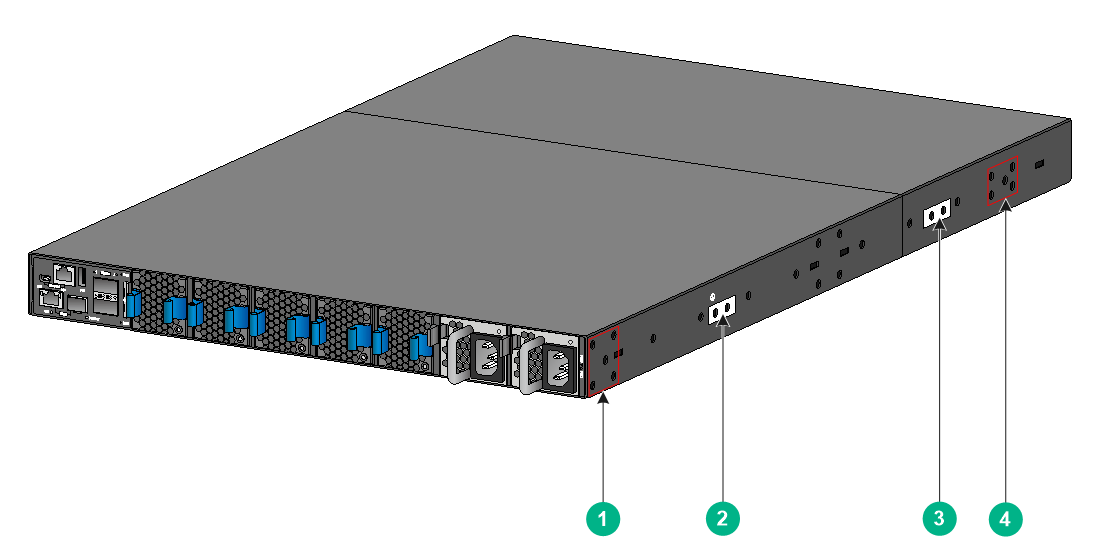
|
(1) Power module-side installation position for the mounting bracket |
|
|
(2) Primary grounding point |
(3) Auxiliary grounding point |
|
(4) Port-side installation position for the mounting bracket |
|
Figure2-23 Mounting brackets and grounding cable installation positions on the S9850-4C switch
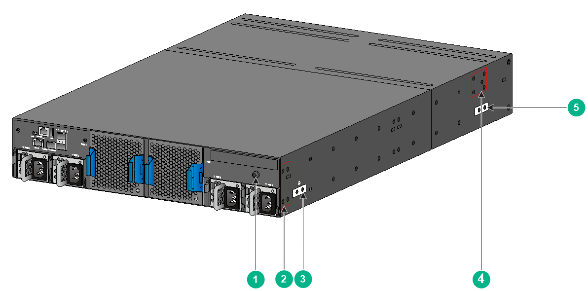
|
(1) Auxiliary grounding point 2 |
(2) Power module-side installation position for the mounting bracket |
|
(3) Primary grounding point |
(4) Port-side installation position for the mounting bracket |
|
(5) Auxiliary grounding point 1 |
|
Figure2-24 Mounting brackets and grounding cable installation positions on the S9850-32H switch
|
(1) Power module-side installation position for the mounting bracket |
|
|
(2) Primary grounding point |
(3) Auxiliary grounding point |
|
(4) Port-side installation position for the mounting bracket |
|
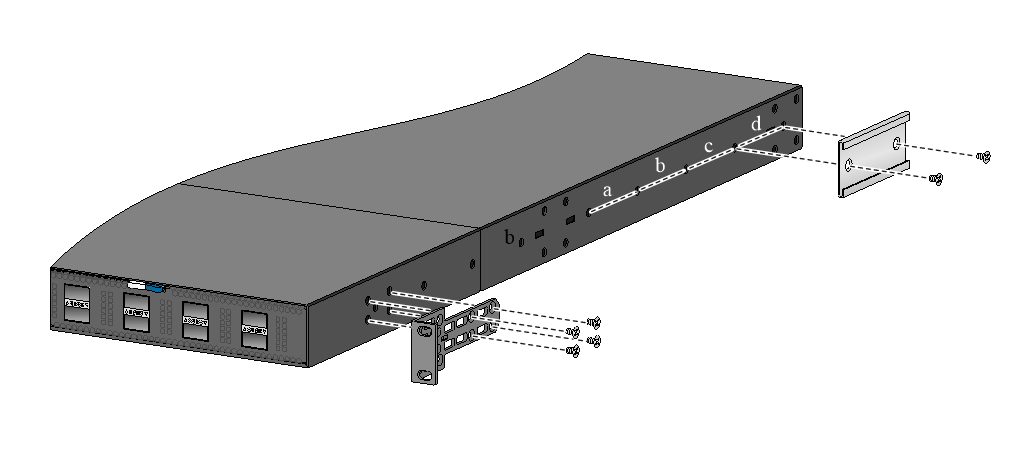
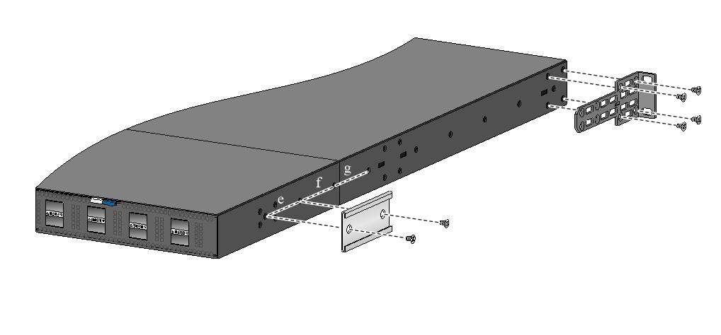
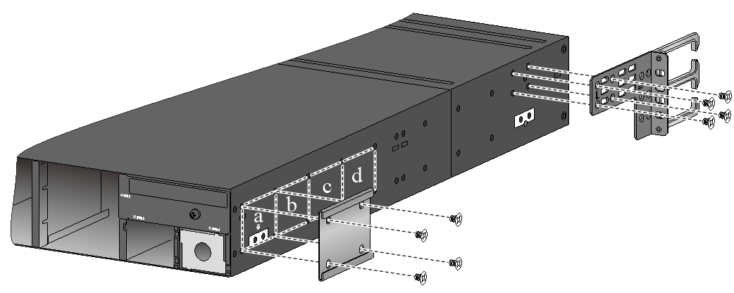
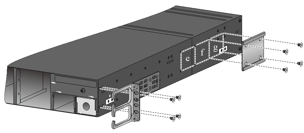
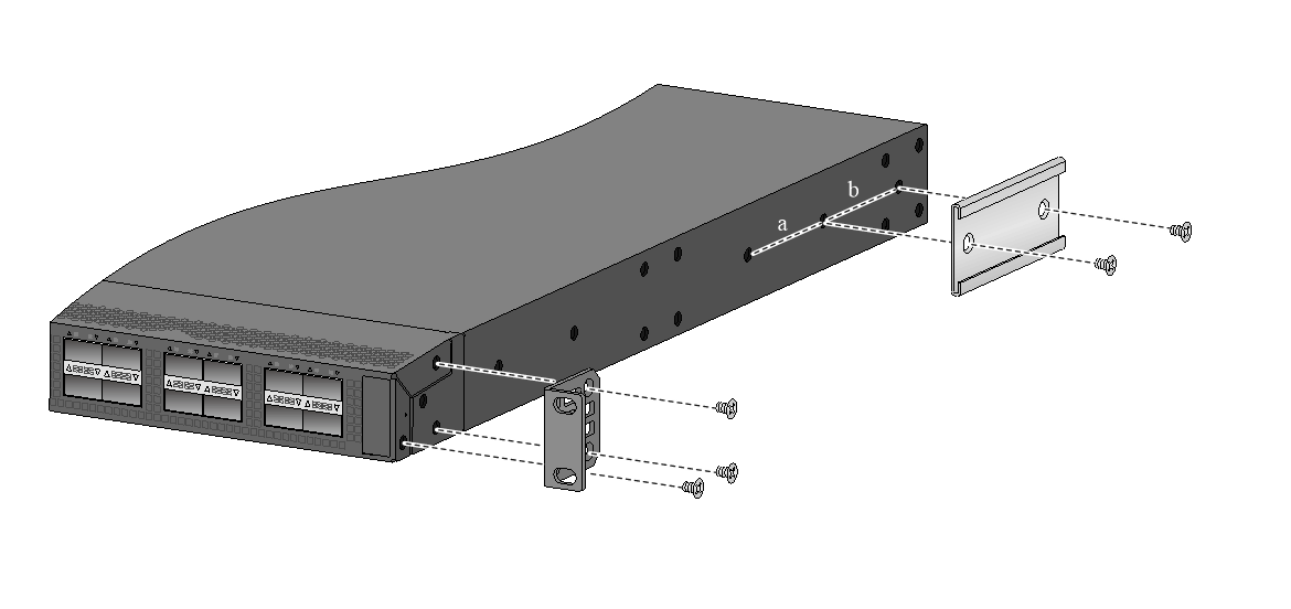
Attaching the mounting brackets and chassis rails to the chassis
1. Place the wide flange of the mounting bracket against the chassis side panel. Align the mounting bracket installation holes with the appropriate screw holes in the chassis. Use the provided M4 screws to attach the mounting bracket to the chassis. As a best practice, use a torque of 12 kgf-cm (1.18 Nm) to fasten the M4 screws.
¡ To install the mounting brackets at the port-side mounting position, see Figure2-25, Figure2-26, Figure2-27, Figure2-37, Figure2-39, Figure2-41, Figure2-31, Figure2-32, and Figure2-33.
Use four installation holes to secure the mounting brackets to the LS-6850-56HF, LS-6850-56HF-H1, S6850-56HF-SAN, S6850-2C, and S9850-4C switches. Use three installation holes to secure the mounting brackets to the S9850-32H switch.
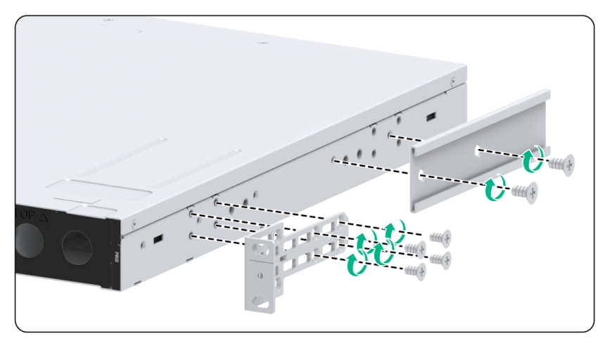
¡ To install the mounting brackets at the power module-side mounting position, see Figure2-28, Figure2-29, Figure2-30, Figure2-38, Figure2-40, Figure2-42, Figure2-34, Figure2-35, and Figure2-36.
Use four installation holes to secure the mounting brackets to the switch.
2. Determine the installation position of the chassis rails based on the position of mounting brackets and the distance between the front and rear rack posts.
Table2-4 Chassis rail installation position
|
Switch model |
Mounting bracket position |
Chassis rail installation position |
Distance between the front and rear rack posts |
|
LS-6850-56HF LS-6850-56HF-H1 S6850-56HF-SAN (long slide rails) |
Port-side mounting position, as shown in Figure2-25 |
Position a |
692 to 788 mm (27.24 to 31.02 in) |
|
Position b |
692 to 853 mm (27.24 to 33.58 in) |
||
|
Power module-side mounting position, as shown in Figure2-28 |
Position c |
692 to 788 mm (27.24 to 31.02 in) |
|
|
Position d |
692 to 853 mm (27.24 to 33.58 in) |
||
|
LS-6850-56HF LS-6850-56HF-H1 S6850-56HF-SAN (super-short slide rails, chassis rails not reaching out of the chassis) |
Port-side mounting position, as shown in Figure2-26 |
Position a |
401 to 500 mm (15.79 to 19.69 in) |
|
Position b |
457 to 565 mm (17.99 to 22.24 in) |
||
|
Power module-side mounting position, as shown in Figure2-29 |
Position c |
401 to 500 mm (15.79 to 19.69 in) |
|
|
Position d |
457 to 565 mm (17.99 to 22.24 in) |
||
|
LS-6850-56HF LS-6850-56HF-H1 S6850-56HF-SAN (super-short slide rails, chassis rails reaching out of the chassis) |
Port-side mounting position, as shown in Figure2-27 |
Position a |
499 to 627 mm (19.65 to 24.69 in) |
|
Position b |
564 to 692 mm (22.20 to 27.24 in) |
||
|
Power module-side mounting position, as shown in Figure2-30 |
Position c |
499 to 627 mm (19.65 to 24.69 in) |
|
|
Position d |
564 to 692 mm (22.20 to 27.24 in) |
||
|
LS-6850-56HF-H3 (long slide rails) |
Port-side mounting position, as shown in Figure2-31 |
634 to 793 mm (24.96 to 31.22 in) |
|
|
Power module-side mounting position, as shown in Figure2-34 |
634 to 728 mm (24.96 to 28.66 in) |
||
|
LS-6850-56HF-H3 (super-short slide rails, chassis rails not reaching out of the chassis) |
Port-side mounting position, as shown in Figure2-32 |
397 to 505 mm (15.63 to 19.88 in) |
|
|
Power module-side mounting position, as shown in Figure2-35 |
343 to 440 mm (13.50 to 17.32 in) |
||
|
LS-6850-56HF-H3 (super-short slide rails, chassis rails reaching out of the chassis) |
Port-side mounting position, as shown in Figure2-33 |
504 to 612 mm (19.84 to 24.09 in) |
|
|
Power module-side mounting position, as shown in Figure2-36 |
439 to 547 mm (17.28 to 21.54 in) |
||
|
S6850-2C |
Port-side mounting position, as shown in Figure2-37 |
Position a |
519 to 638 mm (20.43 to 25.12 in) |
|
Position b |
524 to 703 mm (20.63 to 27.68 in) |
||
|
Position c |
589 to 768 mm (23.19 to 30.24 in) |
||
|
Position d |
654 to 833 mm (25.75 to 32.80 in) |
||
|
Power module-side mounting position, as shown in Figure2-38 |
Position e |
589 to 768 mm (23.19 to 30.24 in) |
|
|
Position f |
524 to 703 mm (20.63 to 27.68 in) |
||
|
Position g |
520 to 638 mm (20.47 to 25.12 in) |
||
|
S9850-4C |
Port-side mounting position, as shown in Figure2-39 |
Position a |
675 to 923 mm (26.57 to 36.34 in) |
|
Position b |
611 to 858 mm (24.06 to 33.78 in) |
||
|
Position c |
546 to 793 mm (21.50 to 31.22 in) |
||
|
Position d |
518 to 728 mm (20.39 to 28.66 in) |
||
|
Power module-side mounting position, as shown in Figure2-40 |
Position e |
518 to 728 mm (20.39 to 28.66 in) |
|
|
Position f |
546 to 793 mm (21.50 to 31.22 in) |
||
|
Position g |
611 to 858 mm (24.06 to 33.78 in) |
||
|
S9850-32H (long slide rails) |
Port-side mounting position, as shown Figure2-41 |
Position a |
621 to 788 mm (24.45 to 31.02 in) |
|
Position b |
621 to 853 mm (24.45 to 33.58 in) |
||
|
Power module-side mounting position, as shown in Figure2-42 |
Position c |
621 to 853 mm (24.45 to 33.58 in) |
|
|
Position d |
621 to 788 mm (24.45 to 31.02 in) |
||
|
S9850-32H (short slide rails) |
Port-side mounting position, as shown in Figure2-41 |
Position a |
401 to 588 mm (15.79 to 23.15 in) |
|
Position b |
454 to 633 mm (17.87 to 24.92 in) |
||
|
Power module-side mounting position, as shown in Figure2-42 |
Position c |
454 to 633 mm (17.87 to 24.92 in) |
|
|
Position d |
401 to 568 mm (15.79 to 22.36 in) |
||
3. Place the chassis rail against the chassis side panel. Align the chassis rail installation holes with the screw holes. Use the provided M4 screws to attach the chassis rail to the chassis. See Figure2-25 to Figure2-40.
As a best practice, use a torque of 12 kgf-cm (1.18 Nm) to fasten the M4 screws.
You can use super-short slide rails and long chassis rails to rack-mount the S6850-56HF switch. Based on the rack depth, install the long chassis rails with the chassis rails not reaching out of the chassis, as shown in Figure2-26 and Figure2-29 or with the chassis rails reaching out of the chassis, as shown in Figure2-27 and Figure2-30.
Figure2-25 Attaching the mounting brackets and chassis rails to the S6850-56HF/S6850-56HF-SAN switch (port-side mounting position for the mounting brackets, long slide rails)
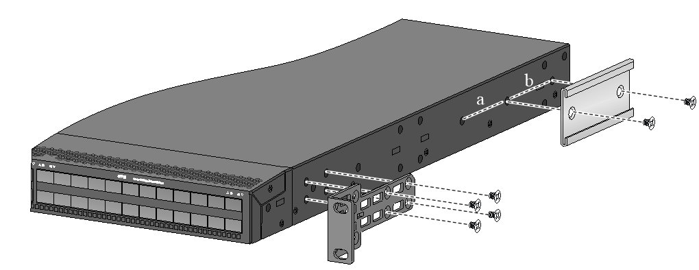
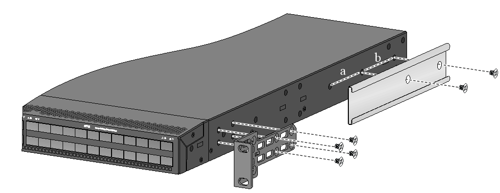
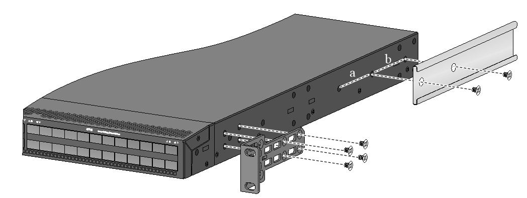
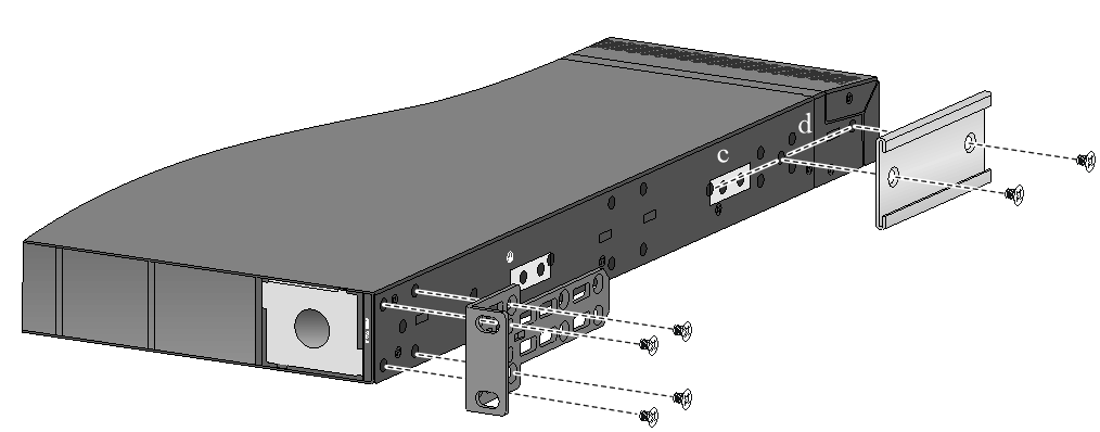
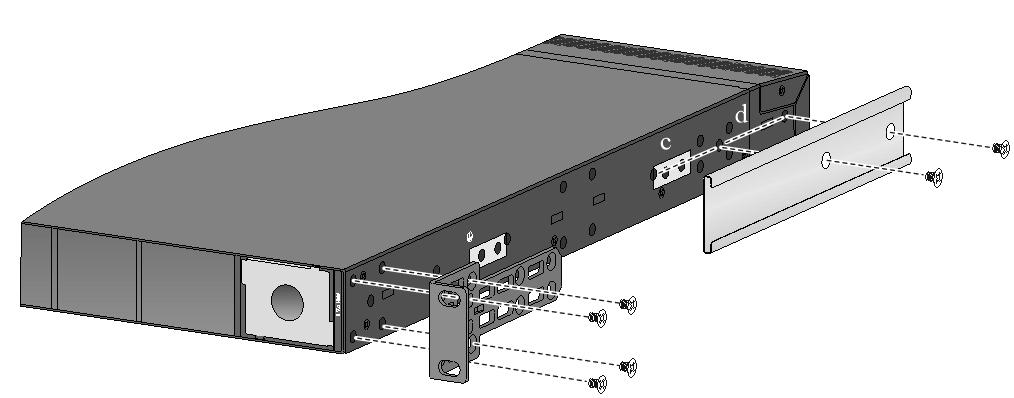
Figure2-30 Attaching the mounting brackets and chassis rails to the S6850-56HF/S6850-56HF-SAN switch (power module-side mounting position for the mounting brackets, super-short slide rails, chassis rails reaching out of the chassis)
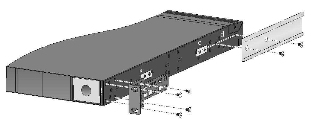
Figure2-31 Attaching the mounting brackets and chassis rails to the LS-6850-56HF-H3 switch (port-side mounting position for the mounting brackets, long slide rails)
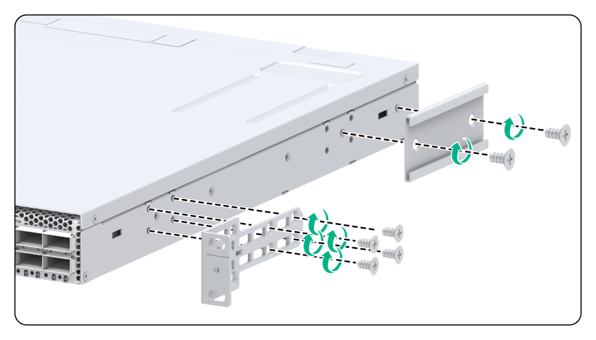
Figure2-32 Attaching the mounting brackets and chassis rails to the LS-6850-56HF-H3 switch (port-side mounting position for the mounting brackets, super-short slide rails, chassis rails not reaching out of the chassis)
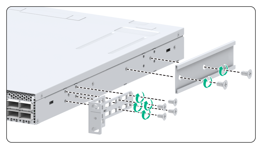
Figure2-33 Attaching the mounting brackets and chassis rails to the LS-6850-56HF-H3 switch (port-side mounting position for the mounting brackets, super-short slide rails, chassis rails reaching out of the chassis)
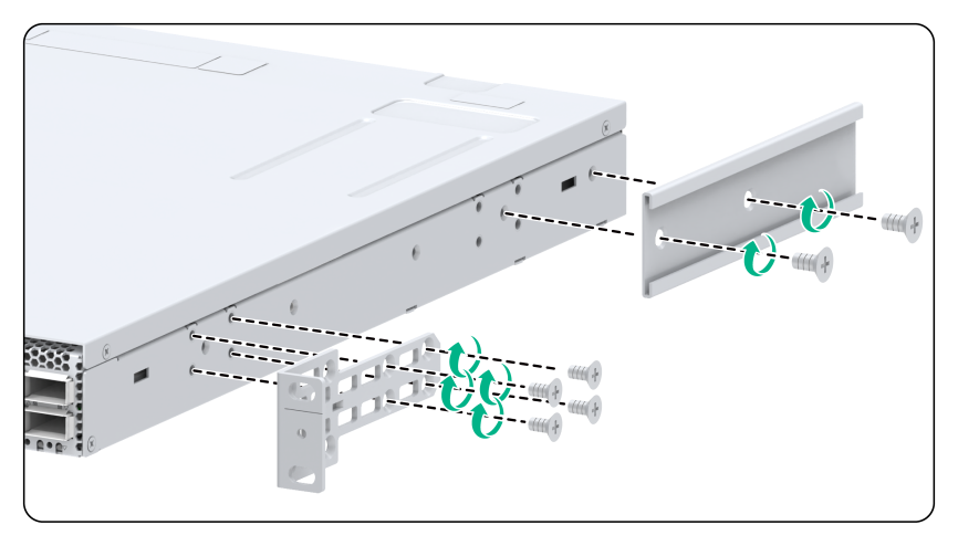
Figure2-34 Attaching the mounting brackets and chassis rails to the LS-6850-56HF-H3 switch (power module-side mounting position for the mounting brackets, long slide rails)

Figure2-35 Attaching the mounting brackets and chassis rails to the LS-6850-56HF-H3 switch (power module-side mounting position for the mounting brackets, super-short slide rails, chassis rails not reaching out of the chassis)
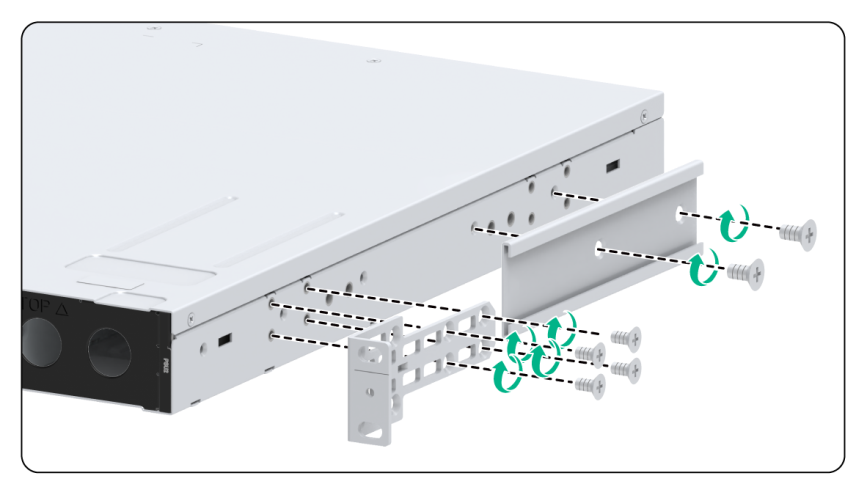
Figure2-36 Attaching the mounting brackets and chassis rails to the LS-6850-56HF-H3 switch (power module-side mounting position for the mounting brackets, super-short slide rails, chassis rails reaching out of the chassis)

|
|
NOTE: Secure the mounting brackets and chassis rails to both sides of the chassis in the same way. |
Connecting the grounding cable to the chassis
|
|
IMPORTANT: · If the grounding cable length or terminal type cannot meet your requirement, make an applicable grounding cable or contact H3C Support. · If you use a grounding point on the side panel to ground the switch, connect the grounding cable to the grounding point before installing the switch in the rack. |
For an LS-6850-56HF, LS-6850-56HF-H1, S6850-56HF-SAN, S6850-2C, or S9850-32H switch, the primary grounding point and auxiliary grounding point are on the left side panel. Both grounding points support a grounding cable that has a single-hole lug or dual-hole lug. Use M5 grounding screws to attach the grounding cable to the switch. Choose the grounding point according to the mounting bracket installation positions.
· If you install the mounting bracket at the port side, connect the grounding cable to the grounding point at the port side.
· If you install the mounting bracket at the power module side, connect the grounding cable to the grounding point at the power module side.
For an S9850-4C switch, the primary grounding point and auxiliary grounding point 1 are on the left side panel, and auxiliary grounding point 2 is on the rear panel. If you use a grounding cable that has a dual-hole lug, connect it to the primary grounding point or auxiliary grounding point 1. If you use a grounding cable that has a single-hole lug, connect it to auxiliary grounding point 2. Use M5 grounding screws to attach the grounding cable to the switch. Choose the grounding point according to the mounting bracket installation positions.
For an LS-6850-56HF-H3 switch, the rear panel has a grounding point and the side panel has two grounding points. The primary grounding point has a grounding sign. As a best practice, use a grounding point on the rear panel. All grounding points support a grounding cable that has a single-hole lug or dual-hole lug. Use M5 grounding screws to attach the grounding cable to the switch.
To connect the grounding cable:
1. Choose a grounding point as required.
2. Unpack the grounding cable and grounding screws.
3. Use the grounding screws to attach the grounding lug of the grounding cable to the grounding holes at the grounding point. Use a screwdriver to tighten the screws. See Figure2-43, Figure2-44, and Figure2-45.
As a best practice, use a torque of 30 kgf-cm (2.94 Nm) to fasten the grounding screws.
Figure2-43 Attaching a grounding cable that has a single-hole lug to the grounding point (LS-6850-56HF)
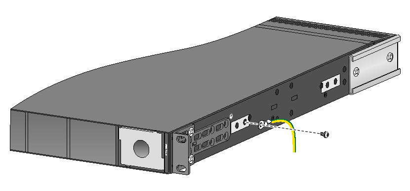
Figure2-44 Attaching a grounding cable that has a dual-hole lug to the grounding point (LS-6850-56HF)

Figure2-45 Attaching a grounding cable to auxiliary grounding point 2 on the S9850-4C switch
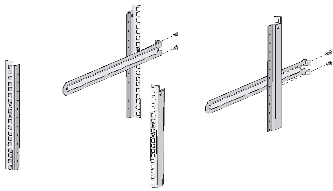
Attaching the slide rails to the rack
The procedure is the same for attaching 1U and 2U slide rails to the rack. This section uses the 1U slide rails as an example.
To attach the slide rails to the rack:
1. Identify the planned slide rail installation position in the rack.
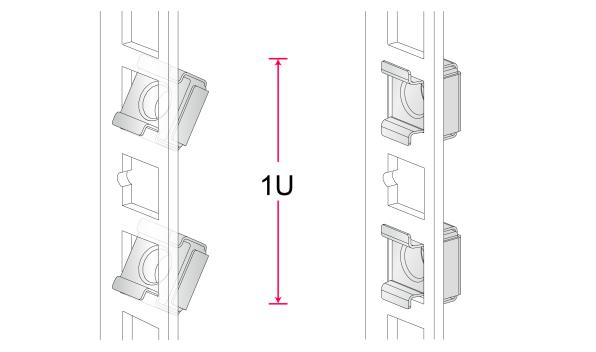
Plan a 1U rack space for installation of 1U slide rails and a 2U rack space for installation of 2U slide rails. Figure2-46 shows a standard 1U rack space.
In a standard 1U rack space, there are three installation holes, one in the middle for auxiliary installation and one at either end for standard installation. The spacing between two adjacent standard installation holes is slightly smaller than the distance between a standard installation hole and the middle, auxiliary installation hole.
Figure2-46 1U rack space
2. Install cage nuts (user-supplied) in the mounting holes in the rack posts.
3. Align the screw holes in one slide rail with the cage nuts in a rear rack post. Use user-supplied M6 screws to attach the slide rail to the post. See Figure2-47.
As a best practice, use a torque of 30 kgf-cm (2.94 Nm) to fasten the M6 screws.
4. Repeat the preceding steps to attach the other slide rail to the other rear rack post.
Keep the two slide rails at the same height so the slide rails can attach into the chassis rails.
Figure2-47 Installing the 1U slide rails
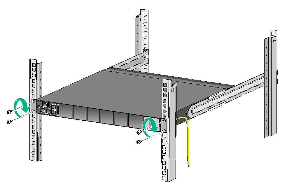
Mounting the switch in the rack
This task requires two people.
To mount the switch in the rack:
1. Wear an ESD wrist strap and make sure it makes good skin contact and is reliably grounded.
2. Verify that the mounting brackets and chassis rails have been securely attached to the switch chassis.
3. Verify that the slide rails have been correctly attached to the rear rack posts.
4. Attach cage nuts (user-supplied) to the front rack posts and make sure they are at the same level as the slide rails.
|
|
CAUTION: To rack-mount the S9850-4C switch by using 2U high mounting brackets and slide rails, use four M6 screws and four cage nuts to attach each mounting bracket to the rack, as shown in Figure2-52 and Figure2-53. |
5. One person performs the following operations:
a. Supporting the bottom of the switch, aligns the chassis rails with the slide rails on the rack posts.
b. Pushes the switch slowly to slide the chassis rails along the slide rails until the mounting brackets are flush with the rack posts.
|
|
IMPORTANT: · If you use long slide rails to rack-mount the S6850-56HF or S6850-56HF-SAN, make sure the front ends of the long slide rails reach out of the chassis rails for a maximum of 20 mm (0.79 in). If you use super-short slide rails to rack-mount the LS-6850-56HF, LS-6850-56HF-H1, or S6850-56HF-SAN, make sure the front ends of the super-short slide rails reach inside the chassis rails for a minimum of 90 mm (3.54 in) after installation. If you use super-short slide rails to rack-mount the LS-6850-56HF-H3, make sure the front ends of the super-short slide rails reach inside the chassis rails for a minimum of 110 mm (4.33 in) after installation. · To rack-mount the S6850-2C and S9850-32H, make sure the front ends of the slide rails reach out of the chassis rails for a minimum of 20 mm (0.79 in) after installation. · To rack-mount the S9850-4C, make sure the front ends of the slide rails reach out of the chassis rails for a minimum of 30 mm (1.18 in) after installation. |
6. Another person uses user-supplied M6 screws to attach the mounting brackets to the rack.
As a best practice, use a torque of 30 kgf-cm (2.94 Nm) to fasten the M6 screws.
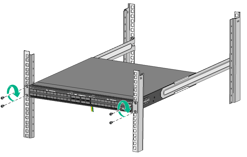
Figure2-49 Mounting the S6850-56HF/S6850-56HF-SAN switch in the rack (power module-side mounting position for the mounting brackets on the LS-6850-56HF)
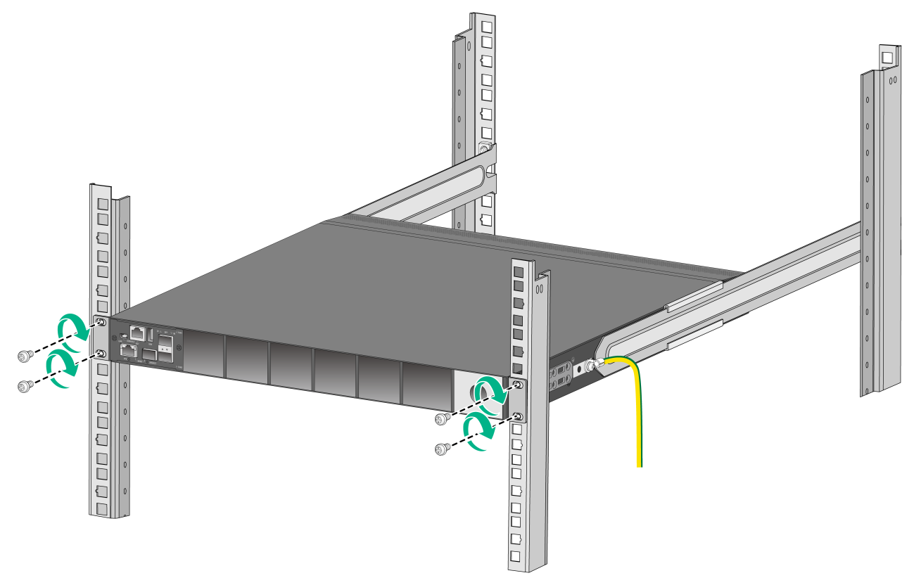
Figure2-50 Mounting the S6850-2C switch in the rack (port-side mounting position for the mounting brackets)
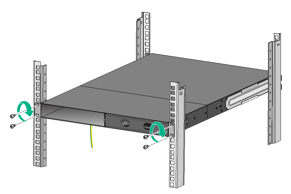
Figure2-51 Mounting the S6850-2C switch in the rack (power module-side mounting position for the mounting brackets)
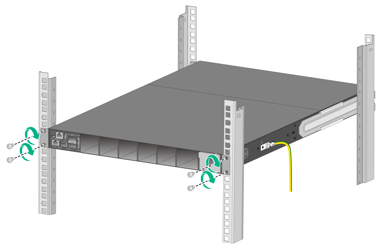
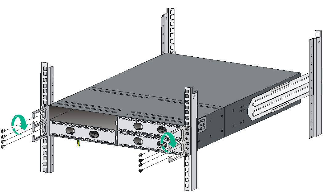
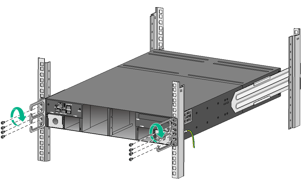
Figure2-54 Mounting the S9850-32H switch in the rack (port-side mounting position for the mounting brackets)
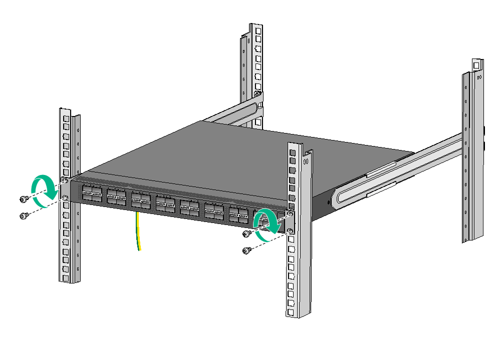
Figure2-55 Mounting the S9850-32H switch in the rack (power module-side mounting position for the mounting brackets)
Grounding the switch
|
|
CAUTION: · Correctly connecting the grounding cable is crucial to lightning protection and EMI protection. · Connect the grounding cable to the grounding system in the equipment room. Do not connect it to a fire main or lightning rod. |
The power input end of the switch has a noise filter, whose central ground is directly connected to the chassis to form the chassis ground (commonly known as PGND). You must securely connect this chassis ground to the earth so the faradism and leakage electricity can be safely released to the earth to minimize EMI susceptibility of the switch.
You can ground a switch by using a grounding strip at the installation site.
|
|
NOTE: · The grounding terminals in this section are for illustration only. · As a best practice to guarantee the grounding effect, use the grounding cable provided with the switch to connect to the grounding strip in the equipment room. |
To connect the grounding cable:
1. Attach the two-hole grounding lug of the grounding cable to a grounding point on the chassis. For more information, see "Connecting the grounding cable to the chassis."
2. Remove the hex nut of a grounding post on the grounding strip.
3. Attach the ring terminal of the grounding cable to the grounding post on the grounding strip, and secure the ring terminal to the grounding post with the hex nut.
Figure2-56 Connecting the grounding cable to a grounding strip
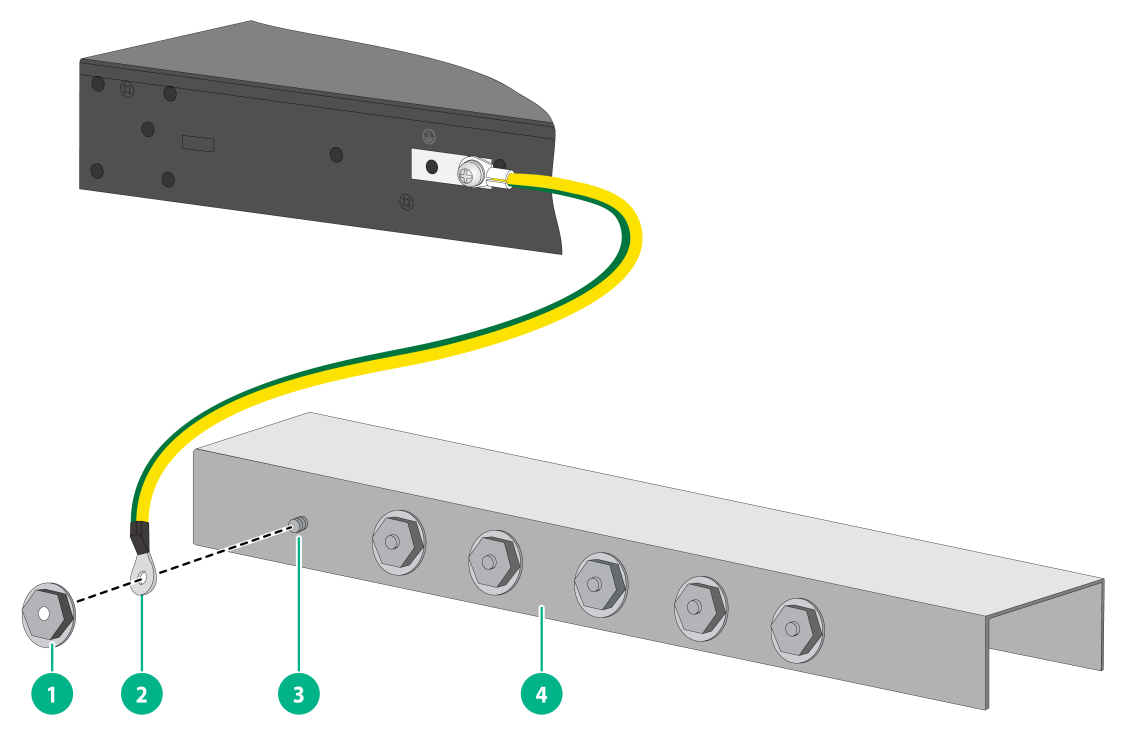
|
(1) Hex nut |
(2) Ring terminal |
|
(3) Grounding post |
(4) Grounding strip |
Installing/removing fan trays
|
|
CAUTION: The switch has multiple fan tray slots. To ensure good ventilation of the switch, follow these guidelines to install and remove fan trays: · The switch comes with the fan tray slots empty. As a best practice for adequate heat dissipation of the switch, fully configure the switch with fan trays of the same model. If the number of installed fan trays is less than the minimum required number, the device will output an error message and does not power up. · Make sure all slots have a module or filler panel installed when the switch is operating. · If multiple fan trays fail on an operating S6850-56HF, S6850-56HF-SAN, S6850-2C, or S9850-32H switch, do not remove the fan trays at the same time. Replace the fan trays one after another and finish replacing a fan tray within 3 minutes. · If a fan tray fails on an operating S9850-4C switch, replace the fan tray immediately and keep the failed fan tray in position before replacement. If two fan trays fail, finish replacing the fan trays within 1 minute. |
|
|
CAUTION: · Do not touch any bare cables or terminals on the fan tray. · Do not place the fan tray in a wet area, and prevent liquid from entering into the fan tray. · When an internal circuit or component of the fan tray fails, contact H3C Support. Do not remove any component from the fan tray yourself. |
The installation and removal procedures are the same for fan trays of different models. The following installation and removal procedures use the LSWM1FANSA and FAN-40B-1-C fan trays as examples.
Installing a fan tray
|
|
CAUTION: To prevent damage to the fan tray or the connectors on the backplane, insert the fan tray gently. If you encounter a hard resistance while inserting the fan tray, pull out the fan tray and insert it again. |
|
|
IMPORTANT: Before powering on the switch, make sure the fan tray airflow direction and the preferred airflow direction of the switch are the same. If they are not the same, the system generates traps and logs. You can use the fan prefer-direction command to configure the preferred airflow direction for the switch. By default, the preferred airflow direction of the switch is from the port side to the power module side. For more information about the fan prefer-direction command, see H3C S6805 & S6825 & S6850 & S9850 Switch Series Fundamentals Command Reference. |
Select fan trays for the switch as needed. For the available fan trays and their specifications, see H3C S6850 & S9850 Switch Series Hardware Information and Specifications.
All switch models (except the LS-6850-56HF-H3) supports shipping with fan trays and power modules installed. If your switch came with fan trays preinstalled, skip this section.
To install a fan tray:
1. Wear an ESD wrist strap and make sure it makes good skin contact and is reliably grounded.
2. Unpack the fan tray and verify that the fan tray model is correct.
3. For an LSWM1FANSA fan tray, orient the fan tray with the "TOP" mark on top. For a FAN-40B-1-C fan tray, orient the fan tray with the connector facing downwards. Grasp the handle of the fan tray with one hand and support the fan tray bottom with the other, and slide the fan tray along the guide rails into the slot until the fan tray is fully seated in the slot and has a firm contact with the backplane. See Figure2-57 and Figure2-58.
Figure2-57 Installing an LSWM1FANSA fan tray in the LS-6850-56HF switch
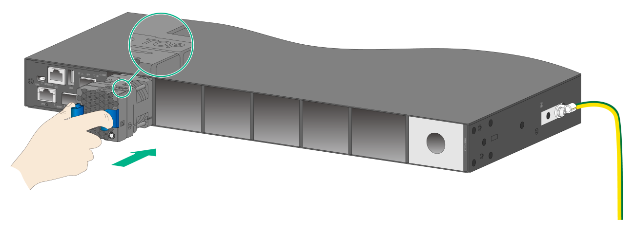
Figure2-58 Installing a FAN-40B-1-C fan tray in the LS-6850-56HF-H3 switch
Removing a fan tray
|
|
WARNING! · Ensure electricity safety and never touch the rotating fans when you hot-swap a fan tray. · To prevent a fan from causing loud noise, do not touch the fan blades and rotation axis, even if the fan is not rotating. |
To remove a fan tray:
1. Wear an ESD wrist strap and make sure it makes good skin contact and is reliably grounded.
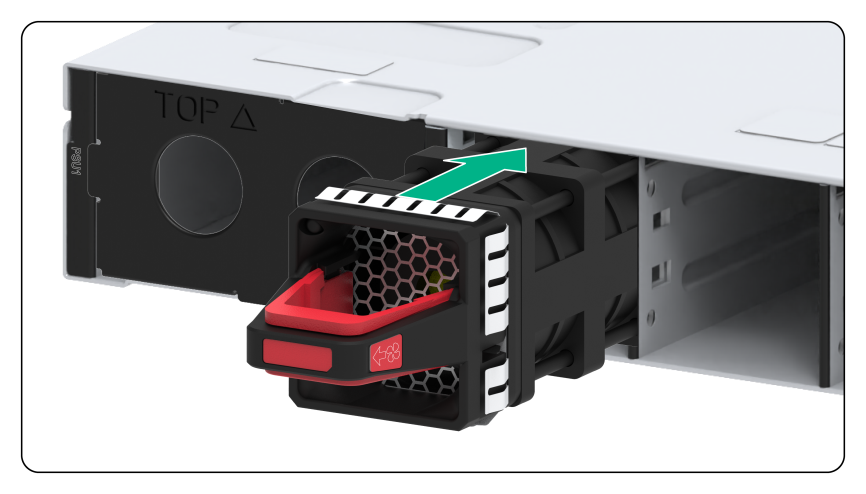
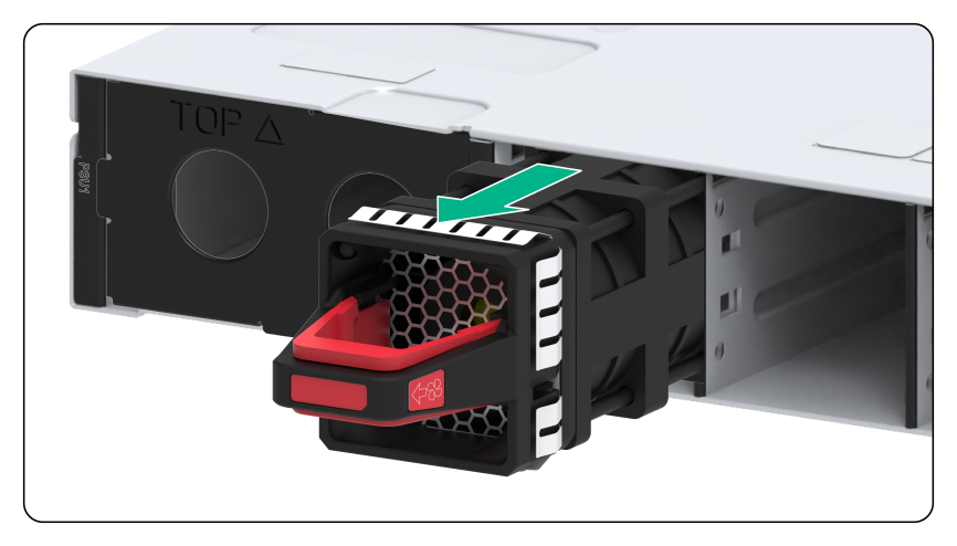
2. For an LSWM1FANSA fan tray, grasp the handle of the fan tray with one hand and pull the fan tray part way out of the slot. Support the fan tray bottom with the other and pull the fan tray completely out of the slot. See Figure2-59.
For a FAN-40B-1-C fan tray, pressing the red part of the handle, pull the fan tray slowly out of the slot along the guide rails. See Figure2-60.
3. Put the removed fan tray in an antistatic bag.
Figure2-59 Removing an LSWM1FANSA fan tray
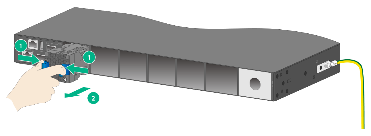
Figure2-60 Removing a FAN-40B-1-C fan tray
Installing/removing power modules
|
|
WARNING! · To avoid bodily injury and device damage, strictly follow the procedures in Figure2-61 and Figure2-62 to install and remove a power module. · Provide a separate circuit breaker for each power module. |
The S6850-56HF, S6850-56HF-SAN, S6850-2C, and S9850-32H switches each have two power module slots. The S9850-4C switch has four power module slots. The S6850-56HF, S6850-56HF-SAN, S6850-2C, and S9850-32H switches each come with one power module slot empty and one installed with a filler panel. The S9850-4C switch comes with two power module slots empty and two installed with filler panels. You can install power modules for the switch as required.
For information about the available power modules, see H3C S6850 & S9850 Switch Series Hardware Information and Specifications.
Figure2-61 Installation procedure
![]()
![]()
Safety guidelines
To prevent device damage and even bodily injury, follow these restrictions and guidelines when you install or remove a power module:
· Always wear an ESD wrist strap and make sure the strap makes good skin contact.
· Before installing a power module, make sure the voltage of the power source is as required by the power module, and the output voltage of the power module is as required by the device.
· Do not touch any bare cables or terminals on the power module.
· Do not place the power module in a wet area, and prevent liquid from entering the power module.
· To avoid power module damage, do not open the power module. When an internal circuit or component of the power supply fails, contact H3C Support.
Installing a power module
|
CAUTION: · Follow the forward inertia of the power module when inserting it into the chassis, and make sure the power module has firm contact with the connectors on the backplane. · To prevent damage to the connectors inside the switch chassis, insert the power module gently. If you encounter a hard resistance while inserting the power module, pull out the power module and insert it again. |
All switch models (except the LS-6850-56HF-H3) supports shipping with fan trays and power modules installed. If your switch comes with power modules preinstalled, skip this section.
The installation procedure is the same for the power modules. The figures in this section use the LS-6850-56HF switch as an example.
To install a power module:
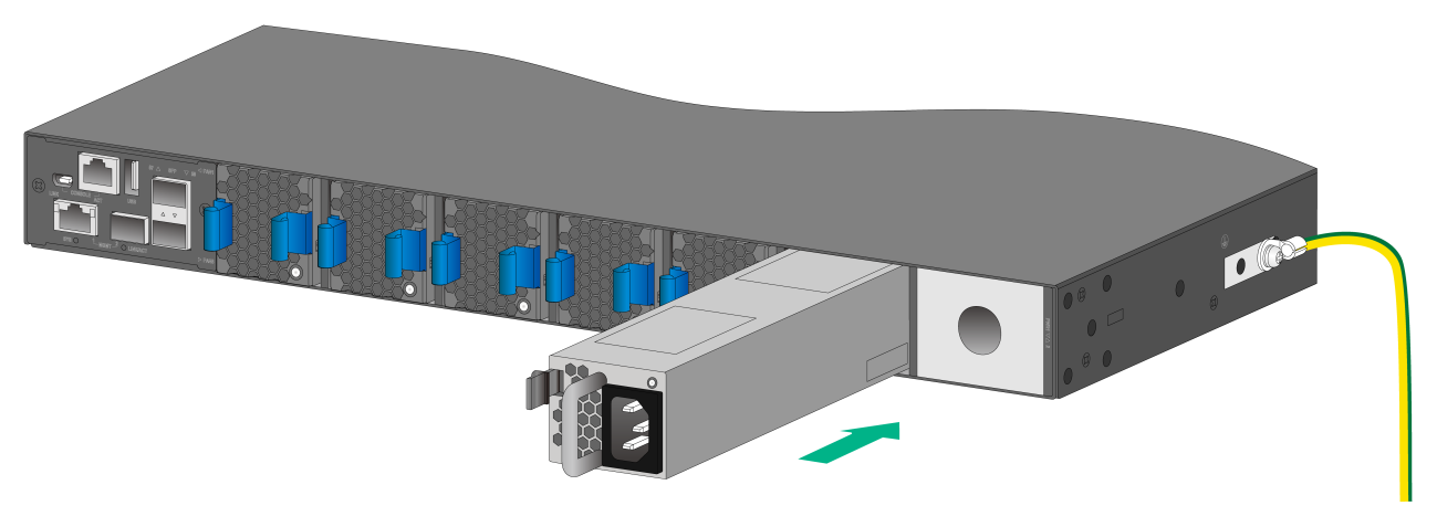
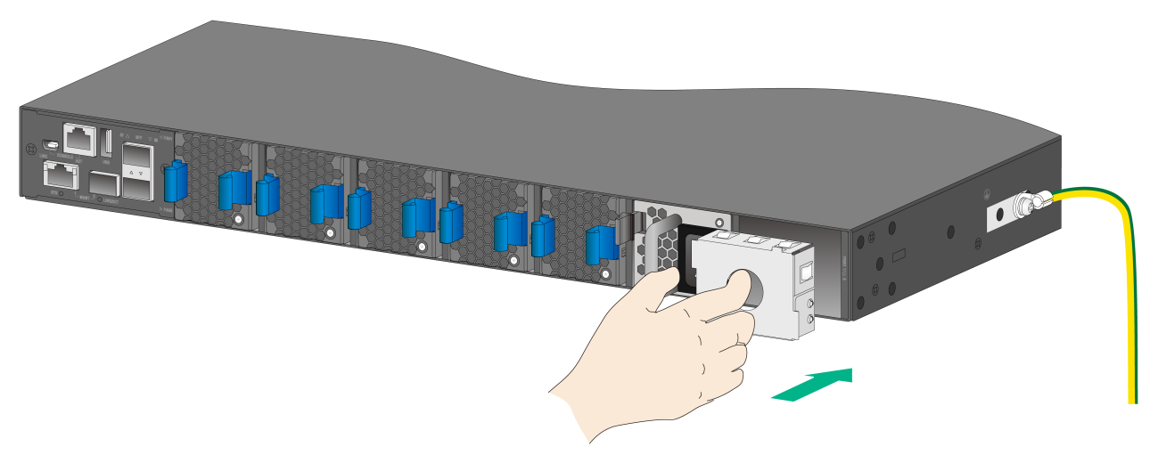
1. Remove the filler panel, if any, from the target power module slot, as shown in Figure2-63.
Figure2-63 Removing a filler panel

2. Unpack the power module and verify that the power module model is correct.
3. Correctly orient the power module with the words on the power module upward. Grasp the handle of the power module with one hand and support its bottom with the other, and slide the power module slowly along the guide rails into the slot.
The slot is foolproof. If you cannot insert the power module into the slot, re-orient the power module rather than use excessive force to push it in.
Figure2-64 Installing a power module (LSVM1AC650)
Removing a power module
|
|
CAUTION: · When an S6850-56HF, S6850-56HF-SAN, S6850-2C, or S9850-32H switch uses two power modules in 1+1 redundancy mode, removing one power module does not affect the operation of the switch. When the switch has only one power module installed, removing the power module powers off the switch. · When an S9850-4C switch has power modules in 2+1 or 2+2 redundancy mode, removing one or two power modules does not affect the operation of the switch. When the switch has only two power modules installed, removing power modules powers off the switch or causes power insufficiency. |
The removal procedure is the same for power modules. The figures in this section use the S6850-56HF switch as an example.
To remove a power module:
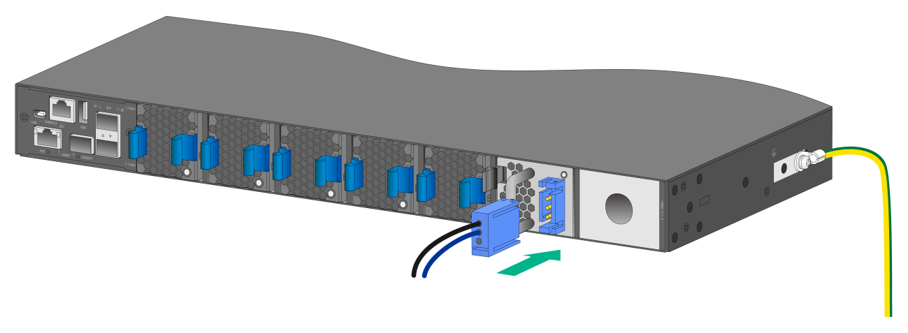
1. Remove the power cord from the power module. To remove a DC power cord, squeeze the tabs on the power cord connector with your thumb and forefinger, and then pull the connector out, as shown in Figure2-65.
2. Hold the handle on the power module with one hand, pivot the latch on the power module with your thumb, and pull the power module part way out of the slot, as shown in Figure2-66.
For an LSVM1AC650 or LSVM1DC650 power module, pivot the latch on the power module to the right.
For an SW-A-PSR550-12A-B, SW-B-PSR550-12A-B, or PSR800-12D-S power module, pivot the latch on the power module to the left.
3. Supporting the power module bottom with one hand, slowly pull the power module out with the other hand.
4. Put the removed power module in an antistatic bag for future use.
5. If you are not to install a new power module, install a filler panel in the slot to ensure good ventilation in the switch, as shown in Figure2-67.
Figure2-65 Removing the DC power cord
|
(1) Press the tabs on the power cord connector with your thumb and forefinger |
|
(2) Pull the power cord connector out |
Figure2-66 Removing an LSVM1AC650 power module
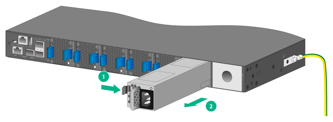
|
(1) Pivot the latch to the right with your thumb |
(2) Pull the power module out |
Figure2-67 Installing a filler panel
Connecting the power cords
|
|
WARNING! Provide a circuit breaker for each power input. When you connect a power cord, make sure the circuit breaker is switched off. |
Connecting an AC power cord
1. Insert the female connector of the AC power cord supplied with the power module into the power receptacle on the power module.
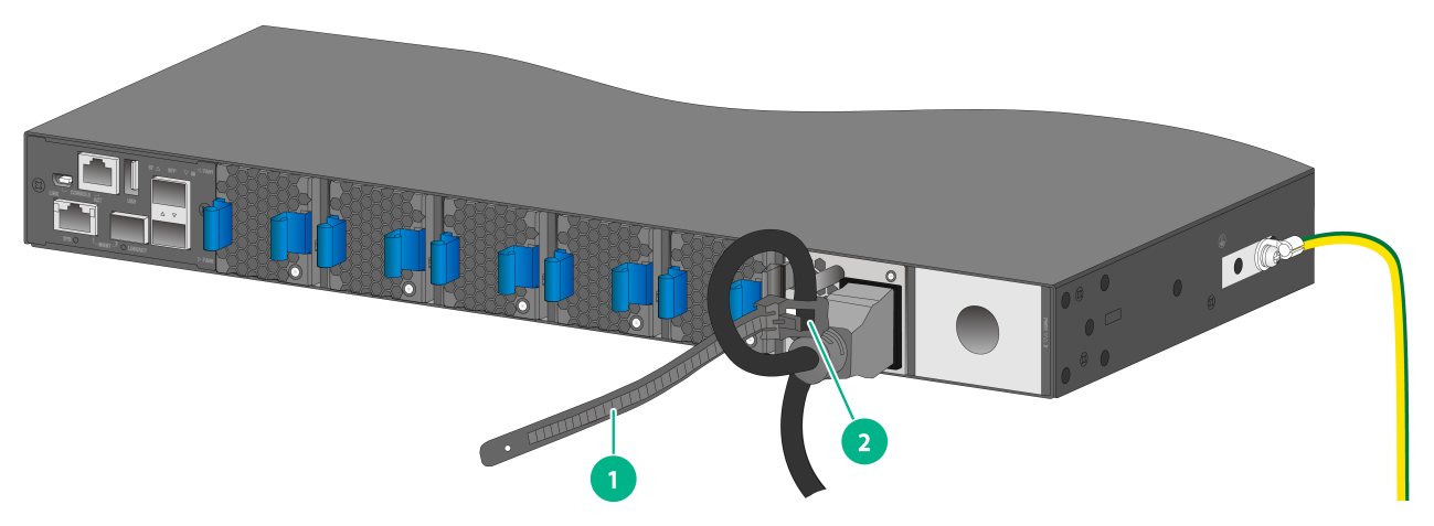
2. For an LSVM1DC650 power module, use a cable tie to secure the power cord to the handle of the power module, as shown in Figure2-68.
For an SW-A-PSR550-12A-B or SW-B-PSR550-12A-B power module, use a Velcro cable strap to secure the power cord to the handle of the power module, as shown in Figure2-69.
3. Connect the other end of the power cord to an AC power outlet.
Figure2-68 Connecting an AC power cord to the LSVM1AC650 power module
|
(1) Cable tie |
|
(2) Tighten the cable tie to secure the power cord to the handle of the power module |
Figure2-69 Connecting an AC power cord to the SW-A-PSR550-12A-B power module
Connecting a DC power cord
1. Align the power cord plug with the power receptacle on the power module, and insert the plug into the receptacle (see Figure2-70).
The plug and receptacle are foolproof. If you cannot insert the plug into the receptacle, re-orient the plug rather than use excessive force to push it in.
2. Use a cable tie to secure the power cord to the handle of the power module, as shown in Figure2-68.
3. Connect the other end of the power cord to the DC power source.
Figure2-70 Connecting a DC power cord to the LSVM1DC650 power module
Installing/removing expansion modules
|
|
CAUTION: When you install or remove an expansion module, follow these guidelines: · Never touch the components on the expansion module surface with bare hands. · Do not use excessive force. · Do not install or remove an expansion module during the startup of the switch. Hot swapping an expansion module when the switch is operating correctly. |
The S6850-2C switch provides two expansion slots. The S9850-4C switch provides four expansion slots. For the available expansion modules, see H3C S6850 & S9850 Switch Series Hardware Information and Specifications.
The installation and removal procedures are the same for expansion modules. This section installs and removes an LSWM18CQ interface module on the S9850-4C switch.
Installing an expansion module
1. Wear an ESD wrist strap and make sure the wrist strap makes good skin contact and is reliably grounded.
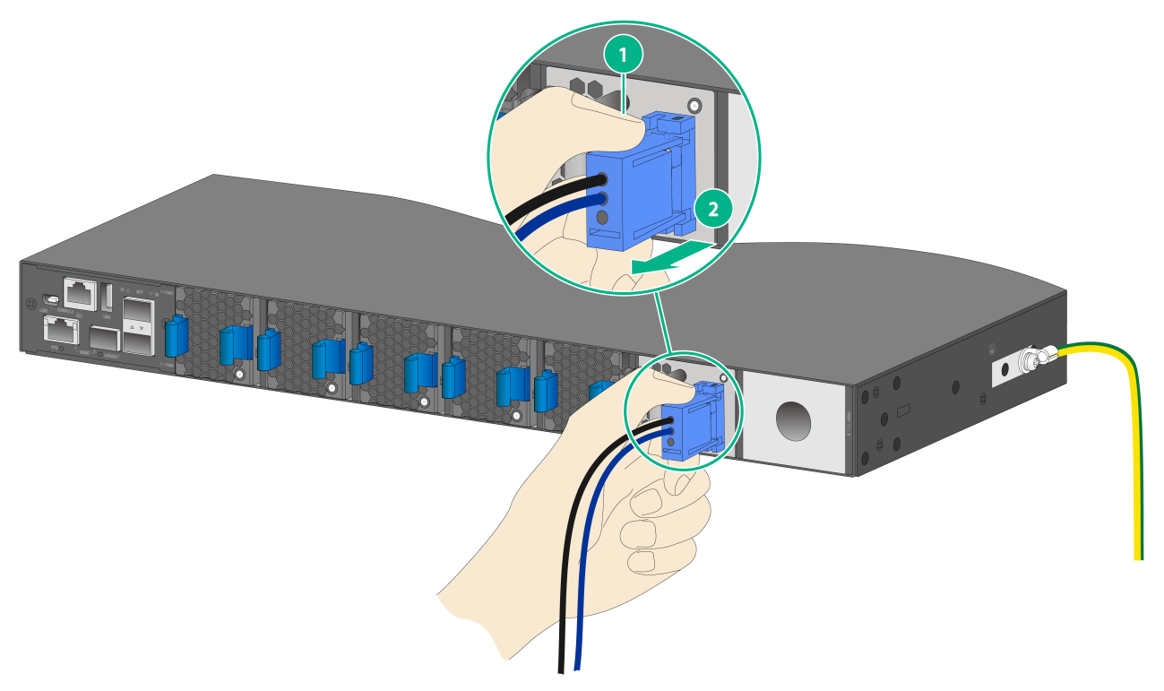
2. (Optional.) If the target expansion slot has a filler panel installed, remove the filler panel, as shown in Figure2-71.
a. Use your thumb and forefinger to hold the filler panel through the two holes.
b. Push right the metal tab in the left hole and pull out the filler panel along the guide rails.
Figure2-71 Removing the filler panel from the expansion slot
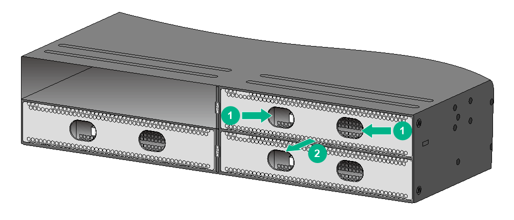
Keep the removed filler panel secure for future use.
3. Unpack the expansion module.
4. Press the latch on the expansion module to release the ejector lever.
Figure2-72 LSWM18CQ interface module
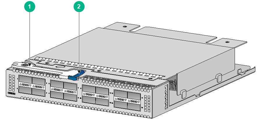
|
(1) Ejector lever |
(2) Latch |
5. Insert the expansion module slowly into the slot along the guide rails, as shown by callout 1 in Figure2-73.
6. Rotate inward the ejector lever as shown by callout 2 in Figure2-73 until the latch locks the ejector lever in place.
Figure2-73 Installing the LSWM18CQ interface module

Removing an expansion module
|
|
CAUTION: · Before you remove an expansion module, remove the cable from it to avoid cable damage. · If you are not to install a new expansion module after removing the original one, install a filler panel in the slot to prevent dust and ensure good ventilation. |
To remove an expansion module:
1. Prepare an anti-static bag.
2. Wear an ESD wrist strap and make sure the wrist strap makes good skin contact and is reliably grounded.
3. Press the latch to release the ejector lever as shown by callout 1 in Figure2-74.
4. Rotate outward the ejector lever as shown by callout 2 in Figure2-74.
5. Pull out the expansion module slowly out of the expansion slot, as shown by callout 3 in Figure2-74.
6. Place the removed expansion module in the anti-static bag.
Figure2-74 Removing an LSWM18CQ interface module

Verifying the installation
After you complete the installation, verify that:
· There is enough space for heat dissipation around the switch, and the rack is stable.
· The grounding cable is securely connected.
· The correct power source is used.
· The power cords are correctly connected.
· All the interface cables are cabled indoors. The switch does not support outdoor cable routing.
3 Accessing the switch for the first time
Connecting the switch to a configuration terminal
You can access all switches except for the LS-6850-56HF-H3 through the serial console port or the mini USB console port. You can access the LS-6850-56HF-H3 only through the serial console port.
Only the mini USB console port is active if you connect both the serial console port and mini USB console port.
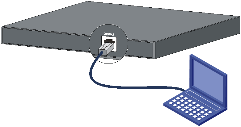
The example uses a serial console cable to connect a console terminal (PC) to the serial console port on the switch.
Figure3-1 Connecting the serial console port to a terminal
As shown in Table3-1, three types of console cables can be used for connecting the switch to a configuration terminal. The switch is not provided with a serial console cable or a mini USB console cable.
Table3-1 Connection methods and console cables
|
Connection method |
Console cable type |
Configuration terminal-side connector |
Switch-side connector |
|
Using the serial console port for connection |
DB9-to-RJ45 console cable |
DB-9 female connector |
RJ-45 connector |
|
USB-to-RJ45 console cable |
USB connector |
RJ-45 connector |
|
|
Using the mini USB console port for connection |
Mini USB console cable |
USB connector |
USB mini-Type B connector |
The signal pinout for the RJ-45 connector of a serial console cable varies by vendor. To avoid abnormal configuration terminal display, use a serial console cable provided by H3C. For more information, see Table3-2. To prepare a serial console cable yourself, make sure the signal pinout for the RJ-45 connector is the same as that shown in Table3-3.
|
Console cable type |
Console cable view |
Product code for the recommended H3C console cable |
|
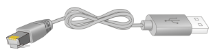
DB9-to-RJ45 console cable |
|
04042967 |
|
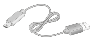
USB-to-RJ45 console cable |
|
0404A1EE |
|
Mini USB console cable |
|
User supplied, |

Connecting the console cable
Connecting a DB9-to-RJ45 console cable
A serial console cable is an 8-core cable, with a crimped RJ-45 connector at one end for connecting to the serial console port of the switch, and a DB-9 female connector at the other end for connecting to the serial port on the console terminal.
Figure3-2 Serial console cable
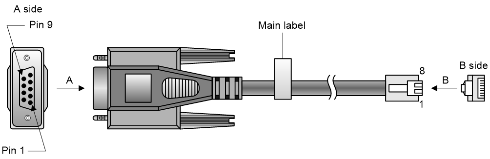
Table3-3 Console port signaling and pinout
|
RJ-45 |
Signal |
DB-9 |
Signal |
|
1 |
RTS |
8 |
CTS |
|
2 |
DTR |
6 |
DSR |
|
3 |
TXD |
2 |
RXD |
|
4 |
SG |
5 |
SG |
|
5 |
SG |
5 |
SG |
|
6 |
RXD |
3 |
TXD |
|
7 |
DSR |
4 |
DTR |
|
8 |
CTS |
7 |
RTS |
To connect a configuration terminal (for example, a PC) to the switch through a DB9-to-RJ45 console cable:
1. Plug the DB-9 female connector of the DB9-to-RJ45 console cable to the serial port on the PC.
2. Connect the RJ-45 connector to the serial console port on the switch.
|
|
NOTE: · Identify the mark on the console port and make sure you are connecting to the correct port. · The serial ports on PCs do not support hot swapping. To connect a PC to an operating switch, first connect the PC end. To disconnect a PC from an operating switch, first disconnect the switch end. |
Connecting a USB-to-RJ45 console cable
|
|
IMPORTANT: · To use a USB-to-RJ45 console cable to connect the switch to a configuration terminal, first download and install the USB-to-RJ45 console driver on the configuration terminal and then connect the USB-to-RJ45 console cable to the configuration terminal. · If you have connected a USB-to-RJ45 console cable to the configuration terminal before driver installation, you must remove and reconnect the USB-to-RJ45 console cable to the configuration terminal. |
For information about the signal pinout for the RJ-45 connector of a USB-to-RJ45 console cable, see Table3-3.
The following procedure describes how to install the driver on the Windows system. To install the driver on other operating systems, see the installation guide in the driver compression package named by the corresponding operating system.
To connect the switch to the configuration terminal through a USB-to-RJ45 console cable:
1. Click the following link, or copy it to the address bar on your browser and download the USB-to-RJ45 console driver.
http://www.h3c.com/en/home/USB_to_RJ45_Console/
2. View the TXT file Read me in the Windows folder to check whether the Windows system of the configuration terminal supports the driver.
3. If the Windows system supports the driver, install PL23XX-M_LogoDriver_Setup_v200_20190815.exe.
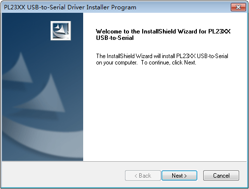
4. Click Next on the welcome page of the driver installation wizard.
Figure3-3 Driver installation wizard
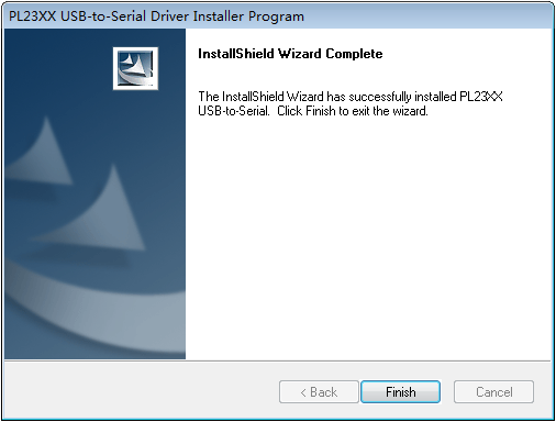
5. Click Finish after the drive installation is completed.
Figure3-4 Finishing the driver installation
6. Connect the standard USB connector of the cable to the USB port of the configuration terminal.
7. Connect the RJ-45 connector of the cable to the console port of the switch.
Connecting the mini USB console cable
A mini USB console cable has a USB mini-Type B connector at one end to connect to the mini USB console port of the switch, and a standard USB Type A connector at the other end to connect to the USB port on the configuration terminal.
To connect to the configuration terminal through the USB mini console cable:
1. Connect the standard USB Type A connector to the USB port of the configuration terminal.
2. Click the following link, or copy it to the address bar on the browser to log in to download page of the USB console driver, and download the driver.
http://www.h3c.com/en/home/USB_Console/,
3. Run Installer to preinstall the driver. After the preinstallation finishes, the system pops up a dialog box to indicate a successful preinstallation.
4. Connect the USB mini-Type B connector to the Mini USB console port on the switch. The system installs the driver automatically.
Setting terminal parameters
To configure and manage the switch through the console port, you must run a terminal emulator program, TeraTermPro or PuTTY, on your configuration terminal. You can use the emulator program to connect a network device, a Telnet site, or an SSH site. For more information about the terminal emulator programs, see the user guides for these programs
The following are the required terminal settings:
· Bits per second—9600.
· Data bits—8.
· Stop bits—1.
· Parity—None.
· Flow control—None.
Powering on the switch
1. Before powering on the switch, verify that the following conditions are met:
¡ All the fan tray slots have a fan tray installed.
¡ The power cords are connected correctly.
¡ The input power voltage is as required by the switch.
¡ The console cable is connected correctly.
¡ The configuration terminal (a PC, for example) has started, and its serial port settings are consistent with the console port settings on the switch.
2. Power on the switch.
During the startup process, you can access BootWare menus to perform tasks such as software upgrade and file management. The BootWare interface and menu options vary by software version. For more information about BootWare menu options, see the software-matching release notes for the device.
3. After the startup completes, you can access the CLI to configure the switch.
For more information about the configuration commands and CLI, see H3C S6805 & S6825 & S6850 & S9850 Switch Series Configuration Guides and H3C S6805 & S6825 & S6850 & S9850 Switch Series Command References.
4 Setting up an IRF fabric
You can use H3C IRF technology to connect and virtualize multiple S6850/S9850 switches into a large virtual switch called an "IRF fabric" for flattened network topology, and high availability, scalability, and manageability.
IRF fabric setup flowchart
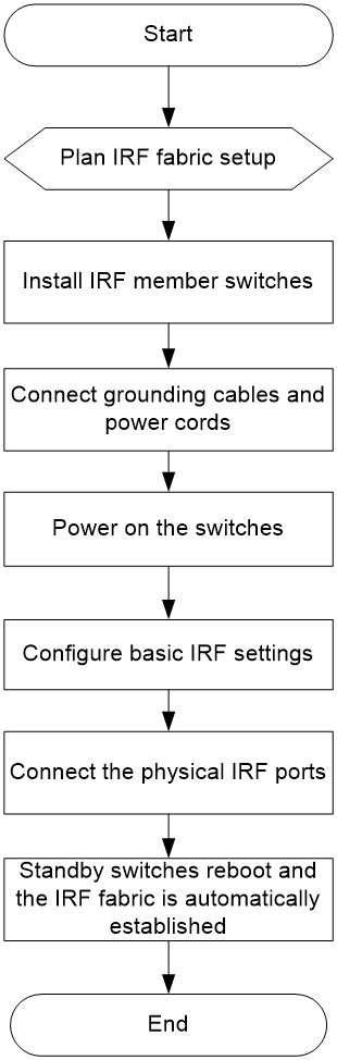
Figure4-1 IRF fabric setup flowchart
To set up an IRF fabric:
|
Step |
Description |
|
1. Plan IRF fabric setup. |
Plan the installation site and IRF fabric setup parameters: · Planning IRF fabric size and the installation site · Identifying the master switch and planning IRF member IDs · Planning IRF topology and connections |
|
2. Install IRF member switches. |
|
|
3. Connect ground wires and power cords. |
See "Grounding the switch" and "Connecting the power cords." |
|
4. Power on the switches. |
N/A |
|
5. Configure basic IRF settings. |
See H3C S6805 & S6825 & S6850 & S9850 Switch Series Virtual Technologies Configuration Guide. |
|
6. Connect the physical IRF ports. |
Connect the physical IRF ports on switches. Use QSFP28/QSFP+ transceiver modules and fibers for connections over long distances. Use QSFP28/QSFP+ cables for connections over short distances. All switches except the master switch automatically reboot, and the IRF fabric is established. |
Planning IRF fabric setup
This section describes issues that an IRF fabric setup plan must cover.
Planning IRF fabric size and the installation site
Determine the number of required IRF member switches, depending on the user density and upstream bandwidth requirements. The switching capacity of an IRF fabric equals the total switching capacities of all member switches.
You can use switches of the same series or use switches of both the S6850 and S9850 series to form an IRF fabric.
Both the S6850 switch series and S9850 switch series support IRF fabrics of up to 10 member devices.
Plan the installation site depending on your network solution as follows:
· Place all IRF member switches in one rack for centralized high-density access.
· Distribute the IRF member switches in different racks to implement the top-of-rack (ToR) access solution for a data center.
As your business grows, you can add member switches into the IRF fabric to increase the switching capacity without any topology change or replacement.
Identifying the master switch and planning IRF member IDs
Determine which switch you want to use as the master for managing all member switches in the IRF fabric. An IRF fabric has only one master switch. You configure and manage all member switches in the IRF fabric at the command line interface of the master switch.
|
|
NOTE: IRF member switches will automatically elect a master. You can affect the election result by assigning a high member priority to the intended master switch. For more information about master election, see H3C S6805 & S6825 & S6850 & S9850 Switch Series Virtual Technologies Configuration Guide. |
Prepare an IRF member ID assignment scheme. An IRF fabric uses member IDs to uniquely identify and manage its members, and you must assign each IRF member switch a unique member ID.
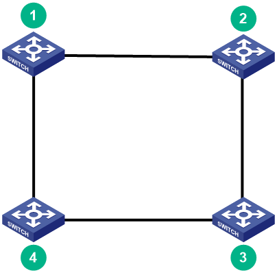
Planning IRF topology and connections
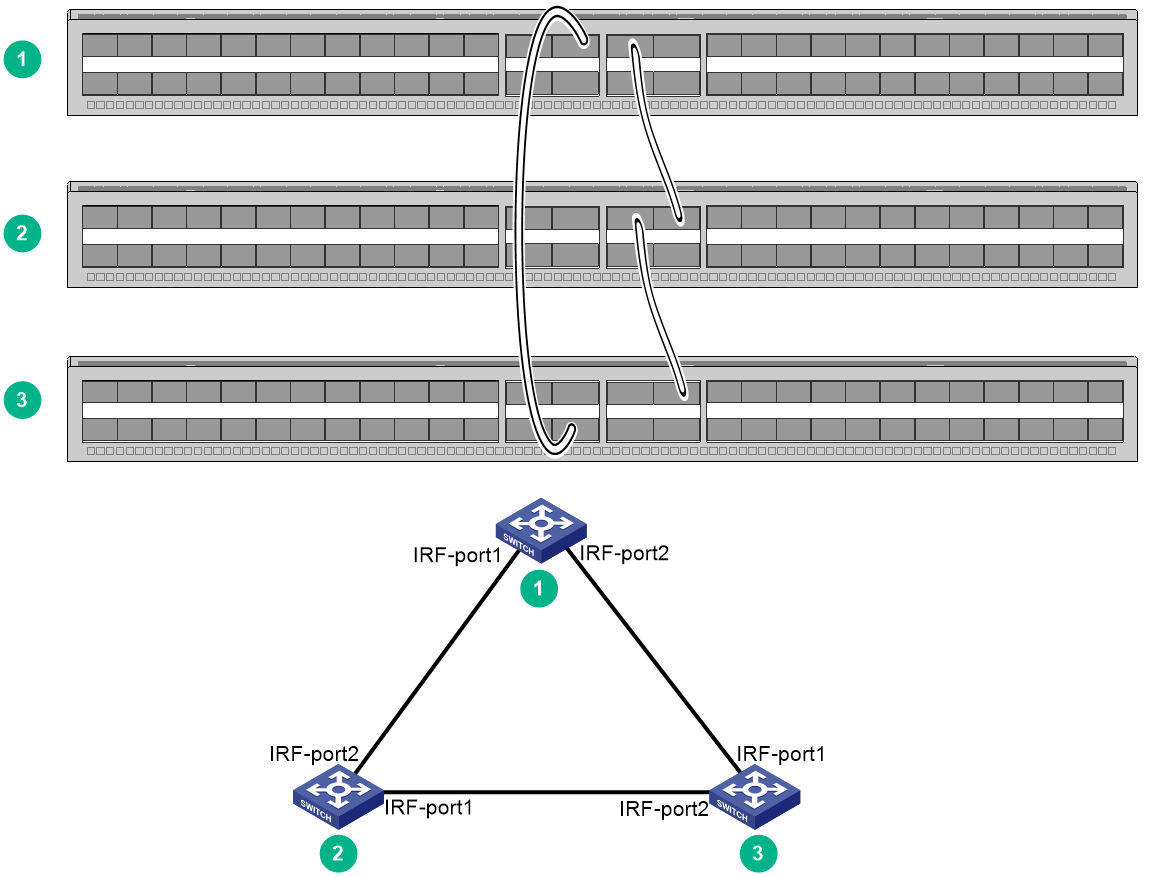
You can create an IRF fabric in daisy chain topology, or more reliably, ring topology. In ring topology, the failure of one IRF link does not cause the IRF fabric to split as in daisy chain topology. Rather, the IRF fabric changes to a daisy chain topology without interrupting network services.
You connect the IRF member switches through IRF ports, the logical interfaces for the connections between IRF member switches. Each IRF member switch has two IRF ports: IRF-port 1 and IRF-port 2. To use an IRF port, you must bind a minimum of one physical port to it.
When connecting two neighboring IRF member switches, you must connect the physical ports of IRF-port 1 on one switch to the physical ports of IRF-port 2 on the other switch.
The IRF port connections in the two figures are for illustration only, and more connection methods are available.
Figure4-2 IRF fabric in daisy chain topology
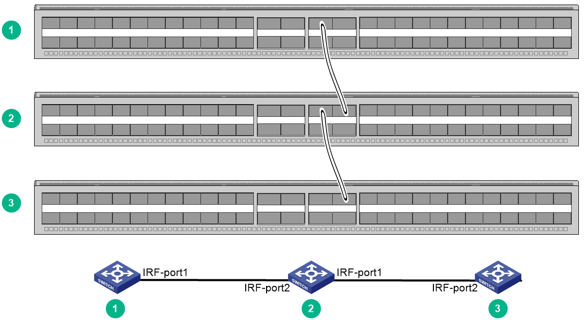
Figure4-3 IRF fabric in ring topology
You can set up IRF links between S6850/S9850 switches as follows:
· Use a QSFP28 module and fiber or a QSFP28 cable to connect QSFP28 ports for a 100-GE IRF physical connection.
· Use a QSFP+ module and fiber or a QSFP+ cable to connect QSFP28 ports for a 40-GE IRF physical connection.
· Use a QSFP+ module and fiber or a QSFP+ cable to connect QSFP+ ports for a 40-GE IRF physical connection.
You can bind several ports to an IRF port for increased bandwidth and availability.
When you use a QSFP+ DAC cable to connect a pair of peer IRF physical interfaces on S6850 or S9850 switch series, follow these restrictions and guidelines:
· The peer interfaces must both be fixed ports or both be ports on expansion interface modules that are the same model.
· If one interface is a fixed QSFP28 port on the rear panel of an S6850-2C switch, the other interface must also be a fixed QSFP28 port on the rear panel of an S6850-2C switch.
Identifying physical IRF ports on the member switches
Identify the physical ports for IRF connections on the member switches according to your topology and connection scheme.
All the QSFP28 ports and QSFP+ ports on the switches (including those on the interface modules), can be used for IRF connections, except for QSFP28 ports on LSWM18CQMSEC interface modules.
When you select ports in a port group for IRF links, you must use all or none of the ports in the group for IRF links. The ports can be bound to different IRF ports.
On an LSWM116Q interface module of the switches, odd and even numbered ports are separated for grouping. The ports are grouped by port number in order, starting from the lowest odd or even number. Each group contains two ports with consecutive odd or even port numbers.
Planning the cabling scheme
You can use QSFP28/QSFP+ cables, or QSFP28/QSFP+ transceiver modules and fibers to connect the S6850/S9850 switches for IRF connections.
If the switches are all in one equipment room, choose QSFP28/QSFP+ cables for IRF connections. If the switches are far away from one another, choose QSFP28/QSFP+ transceiver modules and fibers for IRF connections.
For more information about available cables, see H3C S6850 & S9850 Switch Series Hardware Information and Specifications.
The following subsections describe several IRF connection schemes by using the QSFP28 cables and QSFP28 transceiver modules and fibers. As a best practice, use the ring topology for IRF connections.
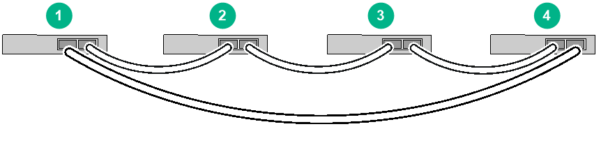
Connecting the IRF member switches in one rack
Figure4-4 shows an example for connecting four IRF member switches in a rack. The switches in the ring topology (see Figure4-5) are in the same order as connected in the rack.
Figure4-4 Connecting the switches in one rack
Connecting the IRF member switches in a ToR solution
You can install IRF member switches in different racks side by side to deploy a top of rack (ToR) solution.
Figure4-6 shows an example for connecting four top of rack IRF member switches. The topology is the same as Figure4-5.
Configuring basic IRF settings
After you install the IRF member switches, power on the switches, and log in to each IRF member switch (see H3C S6805 & S6825 & S6850 & S9850 Switch Series Fundamentals Configuration Guide) to configure their member IDs, member priorities, and IRF port bindings.
Follow these guidelines when you configure the switches:
· Assign the master switch higher member priority than any other switch.
· Bind physical ports to IRF port 1 on one switch and to IRF port 2 on the other switch. You perform IRF port binding before or after connecting IRF physical ports depending on the software release.
· Execute the display irf configuration command to verify the basic IRF settings.
For more information about configuring basic IRF settings, see H3C S6805 & S6825 & S6850 & S9850 Switch Series Virtual Technologies Configuration Guide.
Connecting the physical IRF ports
|
|
CAUTION: Wear an ESD wrist strap when you install transceiver modules, fibers, and cables. For more information, see the installation guide. |
Use transceiver modules and fibers or cables to connect the IRF member switches as planned.
Accessing the IRF fabric to verify the configuration
To verify the basic functionality of the IRF fabric after you finish configuring basic IRF settings and connecting IRF ports:
1. Log in to the IRF fabric through the console port of any member switch.
2. Create a Layer 3 interface, assign it an IP address, and make sure the IRF fabric and the remote network management station can reach each other.
3. Use Telnet or SNMP to access the IRF fabric from the network management station. (See H3C S6805 & S6825 & S6850 & S9850 Switch Series Fundamentals Configuration Guide.)
4. Verify that you can manage all member switches as if they were one node.
5. Display the running status of the IRF fabric by using the commands in Table4-1.
Table4-1 Displaying and maintaining IRF configuration and running status
|
Task |
Command |
|
Display information about the IRF fabric. |
display irf |
|
Display all members' IRF configurations. |
display irf configuration |
|
Display IRF fabric topology information. |
display irf topology |
|
|
NOTE: To avoid IP address collision and network problems, configure at least one multi-active detection (MAD) mechanism to detect the presence of multiple identical IRF fabrics and handle collisions. For more information about MAD detection, see H3C S6805 & S6825 & S6850 & S9850 Switch Series Virtual Technologies Configuration Guide. |
5 Setting up an M-LAG system
Multichassis Link Aggregation (M-LAG) virtualizes two physical devices into one system through multichassis link aggregation to provide device-class high availability and load sharing.
Compared to IRF, M-LAG offers higher network reliability and shorter service interruption during upgrade.
You cannot configure IRF and M-LAG on the same network.
|
|
IMPORTANT: · In Release 6635 and earlier, M-LAG is called DRNI and uses the DRNI set of command keywords in the CLI. · In Release 6710 and later, the device supports both the M-LAG set and DRNI set of command keywords in the CLI by default. The two sets of commands are consistent in the service configuration methods, functions, and output, with only differences in the command keywords. For the differences in the command keywords, see M-LAG configuration in H3C S6805 & S6825 & S6850 & S9850 Switch Series Layer 2—LAN Switching Configuration Guide. |
M-LAG system setup flowchart
Figure5-1 M-LAG system setup flowchart
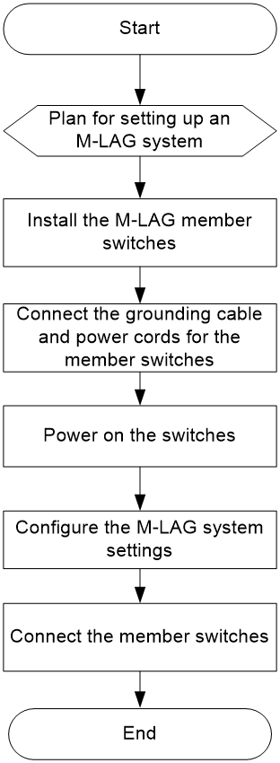
To set up an M-LAG system:
|
Step |
Description |
|
1. Plan for setting up the M-LAG system. |
Plan for setting up the M-LAG system based on the network and device conditions: · Determine the installation locations of the switches. · Reserve physical ports for M-LAG connections. · Plan the cable connection scheme. For more information, see "Planning for setting up an M-LAG system." |
|
2. Install M-LAG member switches. |
|
|
3. Connect grounding cable and power cords for the member switches. |
See "Grounding the switch" and "Connecting the power cords." |
|
4. Power on the switches. |
N/A |
|
5. Configure the M-LAG system settings. |
For detailed information about M-LAG, see M-LAG configuration in H3C S6805 & S6825 & S6850 & S9850 Switch Series Layer 2—LAN Switching Configuration Guide. |
|
6. Connect the member switches. |
Select cables or transceiver modules and optical fibers matching the rate of the physical ports of the peer link and keepalive link for connection. |
Planning for setting up an M-LAG system
Determining device installation locations
An M-LAG system can be set up with only two devices. Reserve sufficient space in the rack for installation of the devices.
You can place the two switches in one cabinet. Alternatively, you can install the switches in two cabinets if you're seeking a top-of-rack access solution in the data center.
Reserving physical ports for M-LAG connection
To set up an M-LAG system, you must establish a peer link and a keepalive link between the two devices.
The M-LAG member devices exchange protocol packets and transmit data traffic over the peer link. An M-LAG system has only one peer link. You can create a peer-link interface on each M-LAG member device, and the link between the two peer-link interfaces is the peer link.
The M-LAG member devices exchange keepalive packets over the keepalive link to detect multi-active collisions when the peer link is down.
Peer link
In addition to protocol packets, the peer link also transmits data packets between the M-LAG member devices when an uplink fails. When you set up the peer link, follow these restrictions and guidelines:
· Configure the peer-link aggregation group as follows:
¡ If an M-LAG member device is a fixed-port device with interface expansion modules, assign ports from multiple interface expansion modules to the aggregation group for the peer-link interface. Make sure at least one member port resides on a different slot than the uplink interfaces.
¡ If an M-LAG member device is a fixed-port device, assign at least two physical interfaces to the aggregation group for the peer-link interface.
· The member ports in the aggregation group for the peer-link interface must have the same speed.
· If an M-LAG system is attached to a large number of servers by using non-M-LAG interfaces, take the size of the traffic sent among those servers into account when you determine the bandwidth of the peer link.
Keepalive link
As a best practice, establish a dedicated direct link between two M-LAG member devices as a keepalive link. Do not use the keepalive link for any other purposes. Make sure the M-LAG member devices have Layer 2 and Layer 3 connectivity to each other over the keepalive link.
You can use management Ethernet interfaces, Layer 3 Ethernet interfaces, Layer 3 aggregate interfaces, or interfaces with a VPN instance bound to set up the keepalive link.
As a best practice, do not use VLAN interfaces for keepalive link setup. If you have to use VLAN interfaces, remove the peer-link interfaces from the related VLANs to avoid loops.
On a device with interface expansion modules, do not use the same module to provide interfaces for setting up the keepalive link and peer link.
Planning the cable connection scheme
Select cables or transceiver modules and optical fibers matching the rate of physical ports of the peer link and the keepalive link for connection.
Cables are short but with high performance and stability, suitable for short-distance connections in the equipment room. Transceiver modules and optical fibers can be combined flexibly and is suitable for longer distance connections.
For information about the transceiver modules and cables supported by the switch, see H3C S6850 & S9850 Switch Series Hardware Information and Specifications.
This following section describes several cable connection schemes that use 100G physical ports for the peer link connection and 25G physical ports for the keepalive link connection, with matching cables or transceiver module and optical fibers.
|
|
NOTE: The physical port locations in the following figures are for illustration only. |
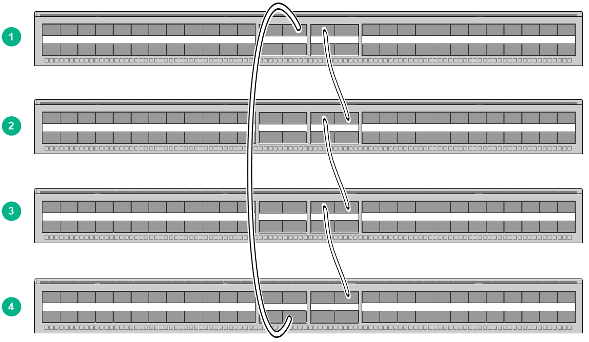
Connecting the member switches in one rack
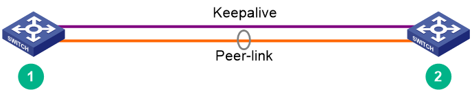
If two M-LAG member devices are installed in the same rack, use the following connection method to connect them as a best practice.
Figure5-2 Connecting two M-LAG member devices are installed in the same rack
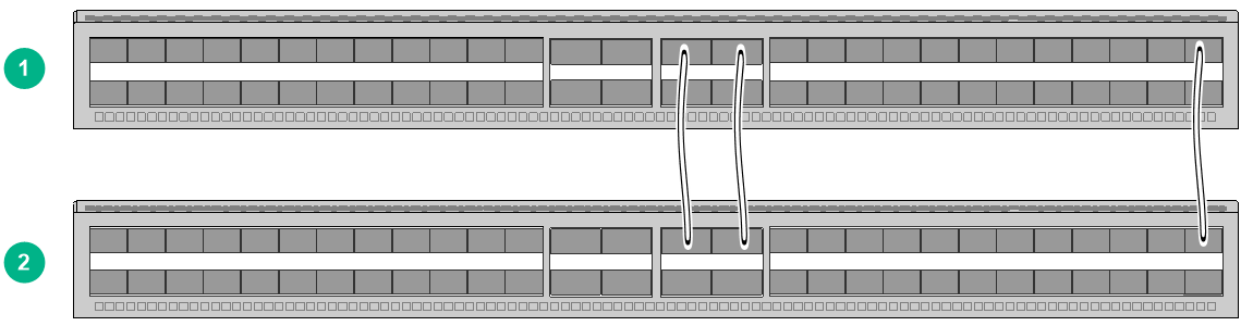
Figure5-3 Connection topology of two M-LAG member devices in the same rack
Top of rack connection scheme
You can install M-LAG member switches in two different racks side by side to deploy a top of rack (ToR) solution as shown in Figure5-4. Use transceiver modules and optical fibers for connection if a large distance exists between the member switches.
Figure5-4 Top of rack connection scheme
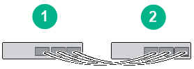
Configuring the M-LAG system settings
After you install the M-LAG member switches, start and log in to each member switch to configure basic M-LAG system settings, including:
· M-LAG system MAC address.
· M-LAG system ID.
· M-LAG system priority.
· Peer-link interface settings.
· Keepalive parameters.
For information about logging in to the switch, see H3C S6805 & S6825 & S6850 & S9850 Switch Series Fundamentals Configuration Guide.
For information about configuring the M-LAG system settings, see M-LAG configuration in H3C S6805 & S6825 & S6850 & S9850 Ethernet Switch Series Layer 2—LAN Switching Configuration Guide.
Restrictions and guidelines
You can set up an M-LAG system with only two member devices. For the M-LAG member devices to be identified as a single M-LAG system, you must configure the same M-LAG system MAC address and M-LAG system priority for them. To distinguish between the two member devices, assign them different M-LAG system IDs.
Make sure the MAC address of the M-LAG system is unique.
For correct packet forwarding, delete M-LAG configuration from an M-LAG member device if it leaves its M-LAG system.
When you bulk shut down physical interfaces on an M-LAG member device for service changes or hardware replacement, shut down the physical interfaces used for keepalive detection prior to the physical member ports of the peer-link interface. If you fail to do so, link flapping will occur on the member ports of M-LAG interfaces.
You must configure the keepalive link interfaces (including physical ports and logical interfaces) as M-LAG reserved interfaces. This ensures that these interfaces will not be MAD down when the peer link fails.
For more configuration restrictions and guidelines and typical configuration examples for the M-LAG system, see H3C Data Center Switches M-LAG Configuration Guide.
Connecting the M-LAG member switches
|
|
CAUTION: Wear an ESD wrist strap when you connect the M-LAG member switches. Make sure the strap makes good skin contact and is reliably grounded. |
Connect the M-LAG member switches based on the network topology and cable connection scheme. For the installation method and restrictions and guidelines for connecting cables or transceiver modules and optical fibers, see the installation guide for them.
Verifying the configuration
To verify the running status of the M-LAG system:
1. Create a Layer 3 interface on a member device, assign it an IP address, and make sure the device and the remote network management station can reach each other.
2. Use Telnet or SNMP to access the device remotely. For more information, see H3C S6805 & S6825 & S6850 & S9850 Switch Series Fundamentals Configuration Guide.
3. Display the running status of the M-LAG system by using the display commands in any view.
Table5-1 Displaying and maintaining M-LAG system configuration and running status
|
Task |
Command |
|
Display M-LAG member device role information. |
display m-lag role |
|
Display M-LAG interface summary information. |
display m-lag summary |
|
Display M-LAG system information. |
display m-lag system |
|
Display detailed information about M-LAG interfaces. |
display m-lag verbose [ interface interface-number ] |
|
|
CAUTION: · In an M-LAG system, all management Ethernet ports on the primary and secondary devices are available for use. From the perspective of the network management system, the two devices in the M-LAG system are independent and you must log in and manage them separately. · To prevent network failures caused by M-LAG system splitting, configure HA after the M-LAG system is set up. For more information, see H3C Data Center Switches M-LAG Configuration Guide. |
6 Maintenance and troubleshooting
Power module failure
Symptom
For an LSVM1AC650 or LSVM1DC650 power module, the power module status LED on the power module is not steady green or flashing green.
For an SW-A-PSR550-12A-B, SW-B-PSR550-12A-B, or PSR800-12D-S power module, the power module status LED on the power module is not steady green.
For more information about the LEDs on a power module, see H3C S6850 & S9850 Switch Series Hardware Information and Specifications.
Solution
To resolve the issue:
1. Verify that the power cord is connected correctly.
2. Verify that the power source is as required by the switch.
3. Verify that the operating temperature of the switch is in the acceptable range and the power module has good ventilation.
4. If the issue persists, contact H3C Support.
To replace a power module, see "Installing/removing power modules."
Fan tray failure
|
|
CAUTION: The LS-6850-56HF, LS-6850-56HF-H1, S6850-56HF-SAN, S6850-2C, and S9850-32H switches each have five fan tray slots. The LS-6850-56HF-H3 switch has four fan tray slots. The S9850-4C switch has two fan tray slots. To replace failed fan trays on an operating switch, follow these guidelines: · If multiple fan trays fail on an operating S6850-56HF, S6850-56HF-SAN, S6850-2C, or S9850-32H switch, do not remove the fan trays at the same time. Replace the fan trays one after another and finish replacing a fan tray within 3 minutes. · If a fan tray fails on an operating S9850-4C switch, replace the fan tray immediately and keep the failed fan tray in position before replacement. If two fan trays fail, finish replacing the fan trays within 1 minute. |
Symptom
· The status LED on an LSWM1FANSA, LSWM1FANSA-SN, LSWM1FANSAB, or LSWM1FANSAB-SN fan tray is steady orange and the system outputs alarm messages.
· The status LED on an LSWM1BFANSC, LSWM1BFANSC-SN, LSWM1BFANSCB, or LSWM1BFANSCB-SN fan tray is steady yellow and the system outputs alarm messages.
· The status LED on a FAN-40B-1-C, FAN-40F-1-D, or FAN-40B-1-D fan tray is steady red and the system outputs alarm messages.
Solution
See "Installing/removing fan trays" to replace the fan tray. If the problem persists, contact H3C Support.
Configuration terminal display problems
No display
Symptom
The configuration terminal displays nothing when the switch is powered on.
Solution
To resolve the issue:
1. Verify that the power system is operating correctly.
2. Verify that the console cable is connected correctly.
3. Verify that the console cable does not have any problems and the terminal settings are correct.
4. If the issue persists, contact H3C Support.
Garbled display
Symptom
The configuration terminal has a garbled display.
Solution
To resolve the issue:
1. Verify that the following settings are configured for the terminal:
¡ Baud rate—9600.
¡ Data bits—8.
¡ Parity—None.
¡ Stop bits—1.
¡ Flow control—None.