- Table of Contents
- Related Documents
-
| Title | Size | Download |
|---|---|---|
| 01-IPsec VPN Configuration Examples | 640.13 KB |
Introduction
The following information provides IPsec VPN configuration examples based on IKE exchange in the following modes:
· Main mode—Applicable to scenarios where both the WAN interfaces on the headquarters and branch gateway routers use fixed public addresses.
· Aggressive mode—Applicable to scenarios where the WAN interface on the headquarters or branch gateway router uses dynamic public addresses (for example, DHCP-assigned IP addresses).
For more information, see “Example: Configuring main mode IPsec VPN” or “Example: Configuring aggressive mode IPsec VPN.”
Prerequisites
This document is not restricted to specific software or hardware versions. Procedures and information in the examples might be slightly different depending on the software or hardware version of the device.
The configuration examples were created and verified in a lab environment, and all the devices were started with the factory default configuration. When you are working on a live network, make sure you understand the potential impact of every command on your network.
The following information is provided based on the assumption that you have basic knowledge of IPsec VPN.
Software versions used
This configuration example was created and verified on ESS 9141L09 of router MSR2630E-X1.
Example: Configuring main mode IPsec VPN
Network configuration
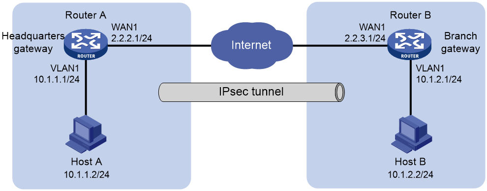
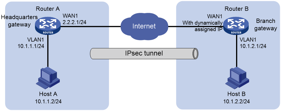
As shown in Figure 1, the headquarters gateway Router A and branch gateway Router B each use a single WAN interface with a fixed public address to connect to the Internet. The headquarters and the branch communicate with each other over the Internet.
To protect data flows between the headquarters and the branch, establish an IPsec tunnel between the gateway routers. Configure the network as follows: The following information describes the deployment in detail:
· Configure Router A and Router B to use preshared key 123456TESTplat&! for authentication.
· Specify the encryption algorithm as 3DES-CBC and the authentication algorithm as MD5.
· Specify the encapsulation mode as the tunnel mode and the security protocol as ESP.
Analysis
To configure IPsec VPN, complete the following configurations on Router A and Router B:
1. Configure basic WAN and LAN settings.
a. Specify the IP address and gateway of the WAN interface on each router.
b. Edit the default IP address of VLAN1 on each router.
2. Add an IPsec policy.
Because the WAN interface on each router uses a fixed IP address to connect to the Internet, configure the IPsec policy to use main mode for phase 1 IKE negotiation.
Restrictions and guidelines
· Editing the IP address of interface VLAN1 will cause Web connection failure. You must use the new IP address to log in to the Web interface again.
· If your network uses dual-WAN or multiple-WAN access, configure a static route on each router to direct the traffic destined for the peer internal network to the WAN interface specified in the IPsec policy. In this example, the routers use single-WAN access. No static route configuration is required. The routers will generate a default route to direct all traffic to the egress gateway.
· Make sure both sides of the IPsec tunnel use the same preshared key, security protocol, encryption algorithm, authentication algorithm, and encapsulation mode.
Procedures
Configuring Router A
Editing the IP address of VLAN1
# Change the IP address of VLAN1 to 10.1.1.1/24. The configuration steps are as follows:
1. Log in to the Web interface. From the navigation pane, select Network > LAN Settings.
2. Click the LAN Settings tab.
3. Click the Edit icon in the Actions column for VLAN1.
4. In the Interface IP Address field, enter 10.1.1.1.
5. In the Subnet Mask field, enter 255.255.255.0.
6. Use the default settings for the other parameters, and click Apply.
Figure 2 Editing the LAN configuration

Configuring WAN1 to connect to the Internet
# In this example, select the single-WAN scenario for Router A, and set the connection mode of the selected WAN interface to fixed IP. The configuration steps are as follows:
1. From the navigation pane, select Network > WAN Settings.
2. On the Scene tab, select Single-WAN Scenario, select WAN1 for Line1, and then click Apply.
3. Click the WAN Settings tab.
4. Click the Edit icon in the Actions column for WAN1.
5. In the Connection Mode field, select Fixed IP.
6. In the IP Address field, enter 2.2.2.1.
7. In the Subnet Mask field, enter 255.255.255.0.
8. In the Gateway field, enter 2.2.2.254.
9. Use the default settings for other parameters. Click Apply.
Figure 3 Configuring the WAN scenario

Figure 4 Editing WAN settings

Configuring the IPsec policy
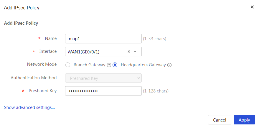
# Specify the network mode as headquarters gateway and the IKE negotiation mode as main mode. The configuration steps are as follows:
1. From the navigation pane, select Virtual Network > IPsec VPN.
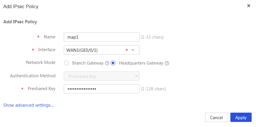
2. Click Add. On the page that opens, configure the following parameters:
¡ In the Name field, enter map1.
¡ In the Interface field, select WAN1.
¡ In the Network Mode field, select Headquarters gateway.
¡ In the Preshared Key field, enter 123456TESTplat&!.
Figure 5 Configuring the IPsec policy
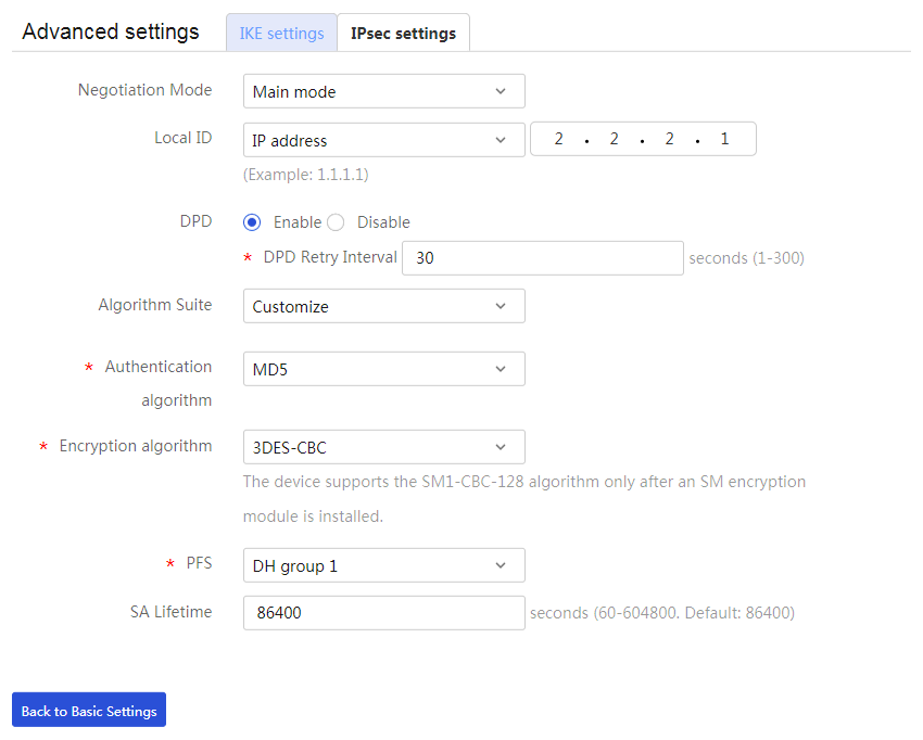
3. Click Show advanced settings. On the page that opens, configure the following parameters:
¡ In the Negotiation Mode field, select Main mode.
¡ In the Local ID field, select IP address, and then enter 2.2.2.1.
¡ In the DPD field, select Enable, and then set the DPD retry interval as needed. (This feature is disabled by default. As a best practice, enable this feature to obtain the availability status of the IPsec tunnel in time.)
¡ In the Algorithm Suite field, select Customize.
¡ In the Authentication algorithm field, select MD5.
¡ In the Encryption algorithm field, select 3DES-CBC.
¡ Use the default settings for other parameters.
Figure 6 IKE settings
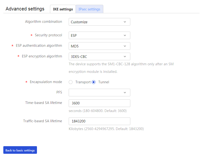
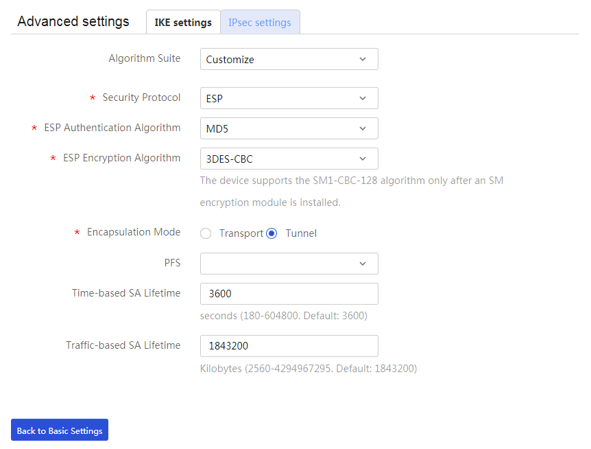
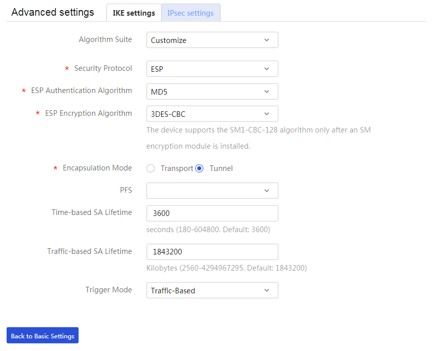
4. Click the IPsec settings tab, and then configure the following parameters:
¡ In the Algorithm Suite field, select Customize.
¡ In the Security Protocol field, select ESP.
¡ In the ESP Authentication Algorithm field, select MD5.
¡ In the ESP Encryption Algorithm field, select 3DES-CBC.
¡ In the Encapsulation Mode field, select Tunnel.
¡ Use the default settings for other parameters.
5. Click Back to Basic Settings to go back to the Add IPsec Policy page. Click Apply.
Figure 7 IPsec settings
Configuring Router B
Editing the IP address of VLAN1
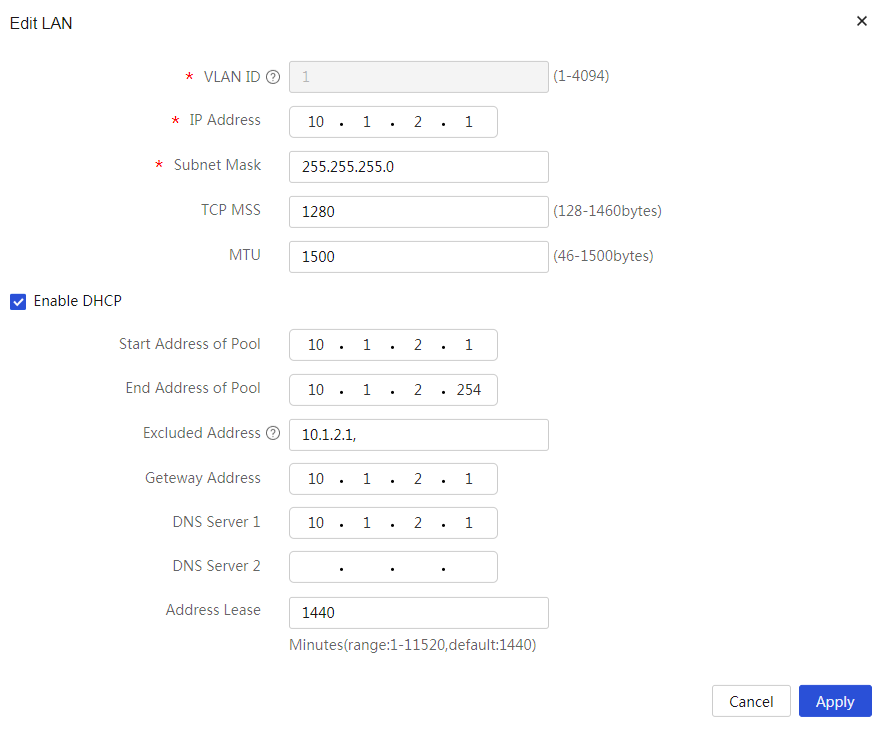
# Change the IP address of VLAN1 to 10.1.2.1/24. The configuration steps are as follows:
1. Log in to the Web interface. From the navigation pane, select Network > LAN Settings.
2. Click the LAN Settings tab.
3. Click the Edit icon in the Actions column for LAN1.
4. In the Interface IP address field, enter 10.1.2.1.
5. In the Subnet Mask field, enter 255.255.255.0.
6. Use the default settings for other parameters, and then click Apply.
Figure 8 Editing LAN settings
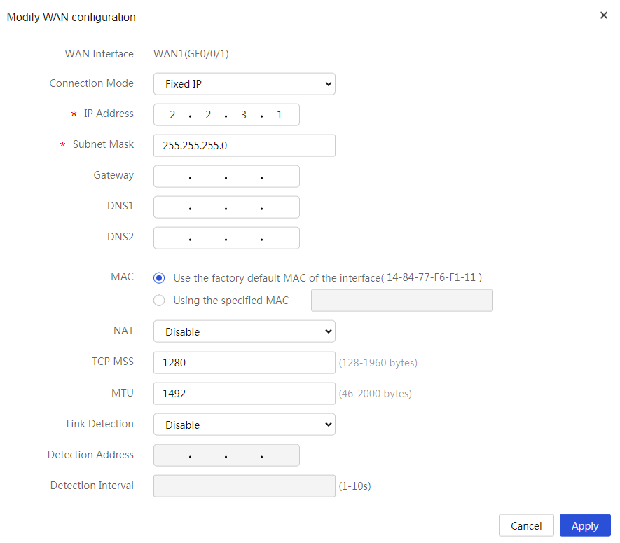
Configuring WAN1 to connect to the Internet
# Configure a single WAN interface using a fixed IP address. The configuration steps are as follows:
1. From the navigation pane, select Network > WAN Settings.
2. On the Scene tab, select Single-WAN Scenario, select WAN1 for Line1, and then click Apply.
3. Click the WAN Settings tab.
4. Click the Edit icon in the Actions column for WAN1.
5. In the Connection Mode field, select Fixed IP.
6. In the IP Address field, enter 2.2.3.1.
7. In the Subnet Mask field, enter 255.255.255.0.
8. In the Gateway field, enter 2.2.3.254.
9. Use the default settings for other parameters. Click Apply.
Figure 9 Editing WAN settings

Figure 10 Editing WAN settings
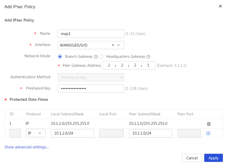
Configuring the IPsec policy
# Specify the network mode as branch gateway and the IKE negotiation mode as main mode. The configuration steps are as follows:
1. From the navigation pane, select Virtual Network > IPsec VPN.
2. Click Add. On the page that opens, configure the following parameters:
¡ In the Name field, enter map1.
¡ In the Interface field, select WAN1.
¡ In the Network Mode field, select Branch Gateway.
¡ In the Peer Gateway Address field, enter 2.2.2.1.
¡ In the Preshared Key field, enter 123456TESTplat&!.
¡ In the Protected Data Flows area, select IP as the protocol to be protected, enter 10.1.2.0/24 in the Local Subnet/Mask field and 10.1.1.0/24 in the Peer Subnet/Mask field, and then click the + icon.
Figure 11 Configuring the IPsec policy
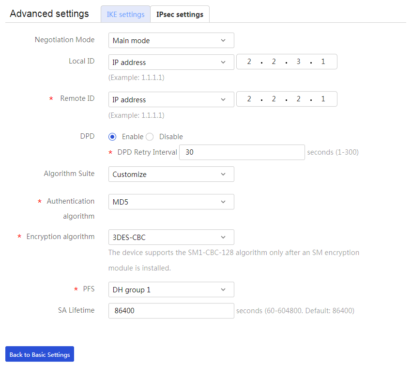
3. Click Show advanced settings. On the page that opens, configure the following parameters:
¡ In the Negotiation Mode field, select Main mode.
¡ In the Local ID field, select IP address, and then enter 2.2.3.1.
¡ In the Remote ID field, select IP address, and then enter 2.2.2.1.
¡ In the DPD field, select Enable, and then set the DPD retry interval as needed.
¡ In the Algorithm Suite field, select Customize.
¡ In the Authentication algorithm field, select MD5.
¡ In the Encryption algorithm field, select 3DES-CBC.
¡ Use the default settings for other parameters.
Figure 12 IKE settings
4. Click the IPsec settings tab, and then configure the following parameters:
¡ In the Algorithm Suite field, select Customize.
¡ In the Security protocol field, select ESP.
¡ In the ESP Authentication Algorithm field, select MD5.
¡ In the ESP Encryption Algorithm field, select 3DES-CBC.
¡ In the Encapsulation Mode field, select Tunnel.
¡ In the Trigger Mode field, select Traffic-Based.
¡ Use the default settings for other parameters.
5. Click Back to Basic Settings to go back to the Add IPsec Policy page. Click Apply.
Figure 13 IPsec settings

Verifying the configuration
1. Verify that Host A can ping Host B successfully.
C:\Users\abc>ping 10.1.2.2
Ping 10.1.2.2 (10.1.2.2): 56 data bytes, press CTRL_C to break
56 bytes from 10.1.2.2: icmp_seq=0 ttl=254 time=2.137 ms
56 bytes from 10.1.2.2: icmp_seq=1 ttl=254 time=2.051 ms
56 bytes from 10.1.2.2: icmp_seq=2 ttl=254 time=1.996 ms
56 bytes from 10.1.2.2: icmp_seq=3 ttl=254 time=1.963 ms
56 bytes from 10.1.2.2: icmp_seq=4 ttl=254 time=1.991 ms
--- Ping statistics for 10.1.2.2 ---
5 packet(s) transmitted, 5 packet(s) received, 0.0% packet loss
round-trip min/avg/max/std-dev = 1.963/2.028/2.137/0.062 ms
C:\Users\abc>
2. On the Web interface, navigate to the Virtual Network > IPsec VPN > Monitor Information page to verify that the IPsec tunnel is successfully established. Status Active indicates successful establishment of the IPsec tunnel.
Example: Configuring aggressive mode IPsec VPN
Network configuration
As shown in Figure 14, the headquarters gateway Router A uses a single WAN interface with a fixed public address to connect to the Internet. The branch gateway Router B uses a single-WAN interface with a DHCP-assigned IP address to connect to the Internet. The headquarters and the branch communicate with each other over the Internet.
To protect data flows between the headquarters and the branch, establish an IPsec tunnel between the routers. Configure the network as follows:
· Configure the HQ and branch routers to use preshared key 123456TESTplat&! for authentication.
· Specify the encryption algorithm as 3DES-CBC and the authentication algorithm as MD5.
· Specify the encapsulation mode as the tunnel mode and the security protocol as ESP.
Analysis
To configure IPsec VPN, complete the following configurations on Router A and Router B:
1. Configure basic WAN and LAN settings.
a. Connect the WAN interfaces on Router A and Router B to the Internet.
b. Change the IP address of VLAN1 on each router.
2. Add an IPsec policy.
One side of the IPsec tunnel (Router B) uses DHCP-assigned IP addresses. To successfully set up the IPsec tunnel, configure the IPsec policy to use aggressive mode for phase 1 IKE negotiation.
Restrictions and guidelines
· Editing the IP address of VLAN interface 1 will cause Web connection failure. You must use the new IP address to log in to the Web interface again.
· If your network uses dual-WAN or multiple-WAN access, configure a static route on each router to direct the traffic destined for the peer internal network to the WAN interface specified in the IPsec policy. In this example, the routers use single-WAN access. No static route configuration is required. The routers will generate a default route to direct all traffic to the egress gateway.
· Make sure both sides of the IPsec tunnel use the same preshared key, security protocol, encryption algorithm, authentication algorithm, and encapsulation mode.
Procedures
Configuring Router A
Editing the IP address of VLAN1
# Change the IP address of VLAN1 to 10.1.1.1/24. The configuration steps are as follows:
1. From the left navigation pane, select Network > LAN Settings.
2. Click the LAN Settings tab.
3. Click the Edit icon in the Actions column for VLAN1.
4. In the Interface IP address field, enter 10.1.1.1.
5. In the Subnet Mask field, enter 255.255.255.0.
6. Use the default settings for the other parameters, and click Apply.
Figure 15 Editing the VLAN configuration

Configuring WAN1 to connect to the Internet
# In this example, select the single-WAN scenario for Router A, and set the connection mode of the selected WAN interface to fixed IP. The configuration steps are as follows:
1. From the navigation pane, select Network > WAN Settings.
2. On the Scene tab, select Single-WAN Scenario, select WAN1 for Line1, and then click Apply.
3. Click the WAN Settings tab.
4. Click the Edit icon in the Actions column for WAN1.
5. In the Connection Mode field, select Fixed IP.
6. In the IP Address field, enter 2.2.2.1.
7. In the Subnet Mask field, enter 255.255.255.0.
8. In the Gateway field, enter 2.2.2.254.
9. Use the default settings for other parameters. Click Apply.
Figure 16 Configuring the WAN scenario
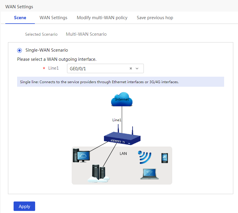
Figure 17 Editing WAN settings

Configuring the IPsec policy
# Specify the network mode as headquarters gateway and the IKE negotiation mode as aggressive mode. The configuration steps are as follows:
1. From the navigation pane, select Virtual Network > IPsec VPN.
2. Click Add. On the page that opens, configure the following parameters:
¡ In the Name field, enter map1.
¡ In the Interface field, select WAN1.
¡ In the Network Mode field, select Headquarters gateway.
¡ In the Preshared Key field, enter 123456TESTplat&!.
Figure 18 Configuring the IPsec policy
3. Click Show advanced settings. On the page that opens, configure the following parameters:
¡ In the Negotiation Mode field, select Aggressive mode.
¡ In the Local ID field, select FDQN, and then enter the FQDN name (for example, www.test.com).
¡ In the DPD field, select Enable, and then set the DPD retry interval as needed. (This feature is disabled by default. As a best practice, enable this feature to obtain the availability status of the IPsec tunnel in time.)
¡ In the Algorithm Suite field, select Customize.
¡ In the Authentication algorithm field, select MD5.
¡ In the Encryption algorithm field, select 3DES-CBC.
¡ Use the default settings for other parameters.
Figure 19 IKE settings

4. Click the IPsec settings tab, and then configure the following parameters:
¡ In the Algorithm Suite field, select Customize.
¡ In the Security Protocol field, select ESP.
¡ In the ESP Authentication Algorithm field, select MD5.
¡ In the ESP Encryption Algorithm field, select 3DES-CBC.
¡ In the Encapsulation Mode field, select Tunnel.
¡ Use the default settings for other parameters.
5. Click Back to Basic Settings to go back to the Add IPsec Policy page. Click Apply.
Configuring Router B
Editing the IP address of VLAN1
# Change the IP address of VLAN1 to 10.1.2.1/24. The configuration steps are as follows:
1. Log in to the Web interface. From the navigation pane, select Network > LAN Settings.
2. Click the LAN Settings tab.
3. Click the Edit icon in the Actions column for VLAN1.
4. In the Interface IP Address field, enter 10.1.2.1.
5. In the Subnet Mask field, enter 255.255.255.0.
6. Use the default settings for other parameters, and then click Apply.
Figure 21 Editing VLAN settings

Configuring WAN1 to connect to the Internet
# Configure a single WAN interface that uses DHCP-assigned IP addresses. The configuration steps are as follows:
1. From the navigation pane, select Network > WAN Settings.
2. On the Scene tab, select Single-WAN Scenario, select WAN1 for Line1, and then click Apply.
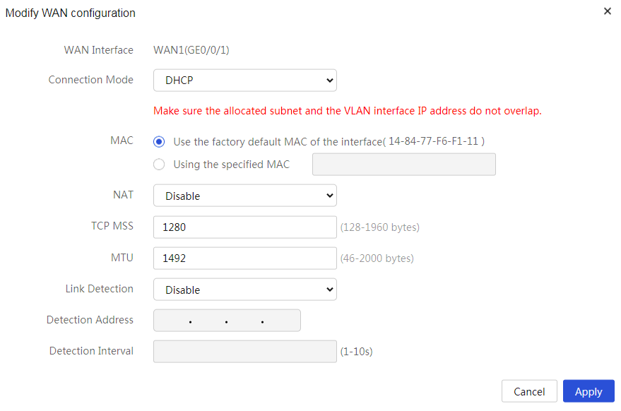
3. Click the WAN Settings tab.
4. Click the Edit icon in the Actions column for WAN1.
5. In the Connection Mode field, select DHCP.
6. Use the default settings for other parameters. Click Apply.
Figure 22 Configuring the WAN scenario
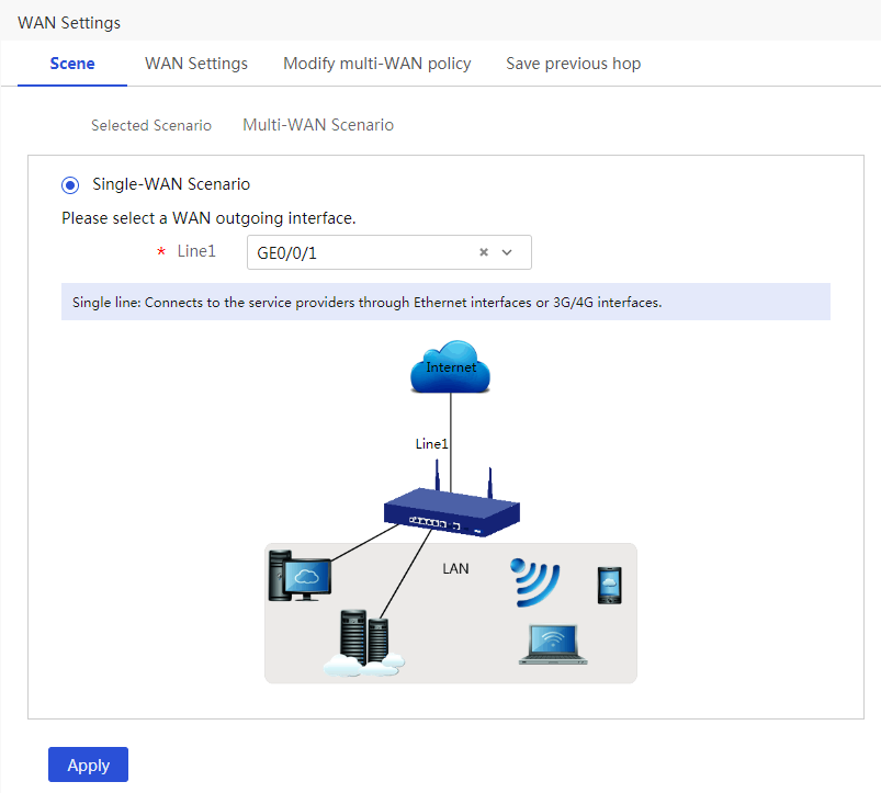
Figure 23 Editing WAN settings
Configuring the IPsec policy
# Specify the network mode as branch gateway and the IKE negotiation mode as aggressive mode. The configuration steps are as follows:
1. From the navigation pane, select Virtual Network > IPsec VPN.
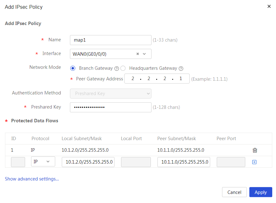
2. Click Add. On the page that opens, configure the following parameters:
¡ In the Name field, enter map1.
¡ In the Interface field, select WAN1.
¡ In the Network mode field, select Branch Gateway.
¡ In the Peer Gateway Address field, enter 2.2.2.1.
¡ In the Preshared Key field, enter 123456TESTplat&!.
¡ In the Protected Data Flows area, select IP as the protocol to be protected, enter 10.1.2.0/24 in the Local Subnet/Mask field and 10.1.1.0/24 in the Peer Subnet/Mask field, and then click the + icon.
Figure 24 Configuring the IPsec policy
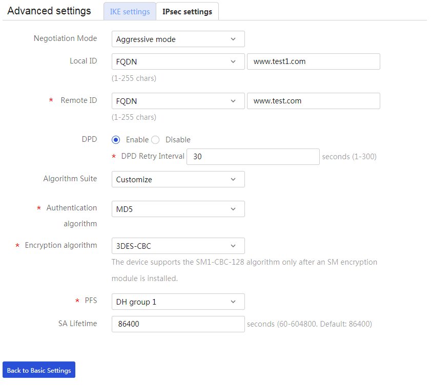
3. Click Show advanced settings. On the page that opens, configure the following parameters:
¡ In the Negotiation Mode field, select Aggressive mode.
¡ In the Local ID field, select FDQN, then enter the FQDN name (for example, www.test1.com).
¡ In the Remote ID field, select FDQN, and then enter the FQDN name (for example, www.test.com).
¡ In the DPD field, select Enable, and then set the DPD retry interval as needed.
¡ In the Algorithm Suite field, select Customize.
¡ In the Authentication algorithm field, select MD5.
¡ In the Encryption algorithm field, select 3DES-CBC.
¡ Use the default settings for other parameters.
Figure 25 IKE Settings
4. Click the IPsec settings tab, and then configure the following parameters:
¡ In the Algorithm Suite field, select Customize.
¡ In the Security Protocol field, select ESP.
¡ In the ESP Authentication Algorithm field, select MD5.
¡ In the ESP Encryption Algorithm field, select 3DES-CBC.
¡ In the Encapsulation Mode field, select Tunnel.
¡ In the Trigger Mode field, select Traffic-Based.
¡ Use the default settings for other parameters.
5. Click Back to Basic settings to go back to the Add IPsec Policy page. Click Apply.
Figure 26 IPsec settings
Verifying the configuration
1. Verify that Host A can ping Host B successfully.
C:\Users\abc>ping 10.1.2.2
Ping 10.1.2.2 (10.1.2.2): 56 data bytes, press CTRL_C to break
56 bytes from 10.1.2.2: icmp_seq=0 ttl=254 time=2.137 ms
56 bytes from 10.1.2.2: icmp_seq=1 ttl=254 time=2.051 ms
56 bytes from 10.1.2.2: icmp_seq=2 ttl=254 time=1.996 ms
56 bytes from 10.1.2.2: icmp_seq=3 ttl=254 time=1.963 ms
56 bytes from 10.1.2.2: icmp_seq=4 ttl=254 time=1.991 ms
--- Ping statistics for 10.1.2.2 ---
5 packet(s) transmitted, 5 packet(s) received, 0.0% packet loss
round-trip min/avg/max/std-dev = 1.963/2.028/2.137/0.062 ms
C:\Users\abc>
2. On the Web interface, navigate to the Virtual Network > IPsec VPN > Monitor Information page to verify that the IPsec tunnel is successfully established. Status Active indicates successful establishment of the IPsec tunnel.
