- Table of Contents
- Related Documents
-
| Title | Size | Download |
|---|---|---|
| 01-Hardware Information and Specifications | 30.60 MB |
Product models and system features
10G/5G/2.5G/1000/100BASE-T Ethernet port
2.5G/1000/100BASE-T Ethernet port
10/100/1000BASE-T Ethernet port
10G/5G/2.5G/1000/100BASE-T Ethernet port LED
2.5G/1000/100BASE-T Ethernet port LED
10/100/1000BASE-T autosensing Ethernet port LED
Product models and system features
Product models
This manual is applicable to the following Ethernet switch products:
|
Product series |
Product models |
Product codes |
|
|
ES4200 series |
Non-PoE models |
ES4200-2T1S-M |
LS-ES4200-2T1S-M |
|
ES4200-4T2ST |
LS-ES4200-4T2ST |
||
|
ES4200-4UMG2X |
LS-ES4200-4UMG2X |
||
|
ES4200-8MG |
LS-ES4200-8MG |
||
|
ES4200-8T2S |
LS-ES4200-8T2S |
||
|
ES4200-8T2ST |
LS-ES4200-8T2ST |
||
|
ES4200-8T2RX-B |
LS-ES4200-8T2RX-B |
||
|
ES4200-8T2RS |
LS-ES4200-8T2RS |
||
|
LS-ES4200-8T2RS-GL |
|||
|
ES4200-4T1MS-B |
LS-ES4200-4T1MS-B |
||
|
ES4200-4T2RMS-B |
LS-ES4200-4T2RMS-B |
||
|
ES4200-16T2RX |
LS-ES4200-16T2RX |
||
|
LS-ES4200-16T2RX-GL |
|||
|
ES4200-24T2X |
LS-ES4200-24T2X |
||
|
PoE models |
ES4200-4P2ST |
LS-ES4200-4P2ST |
|
|
ES4200-8P2ST |
LS-ES4200-8P2ST |
||
|
ES4200-4P2RS |
LS-ES4200-4P2RS |
||
|
LS-ES4200-4P2RS-GL |
|||
|
ES4200-4P2RST |
LS-ES4200-4P2RST |
||
|
ES4200-8P2RS |
LS-ES4200-8P2RS |
||
|
LS-ES4200-8P2RS-GL |
|||
|
ES4200-8P2S |
LS-ES4200-8P2S |
||
|
ES4200-4P2RMS-B |
LS-ES4200-4P2RMS-B |
||
|
ES4200-8P2RX-B |
LS-ES4200-8P2RX-B |
||
|
ES4200-16P2RS |
LS-ES4200-16P2RS |
||
|
LS-ES4200-16P2RS |
|||
|
ES4200-16P2RX-B |
LS-ES4200-16P2RX-B |
||
|
ES4200-24FP2X |
LS-ES4200-24FP2X |
||
|
|
NOTE: · For product selection information, see the switch data sheet at https://www.h3c.com/en/Products_and_Solutions/InterConnect/Switches/. · To view the product and software compatibility, see the release notes. · Switches of the same model but different PIDs might differ in hardware and software features. You can view the PID of a switch on the label located on its cover. |
System features
Non-PoE models
Table 1 Features of the ES4200 series non-PoE models (1)
|
Item |
ES4200-2T1S-M |
ES4200-4T2ST |
ES4200-8T2ST |
||
|
Physical specifications |
|||||
|
Dimensions (H × W × D) |
30 × 44 × 190 mm (1.18 × 1.73 × 7.48 in) |
27 × 130 × 124 mm (1.06 × 5.12 × 4.88 in) |
27 × 185 × 125 mm (1.06 × 7.28 × 4.92 in) |
||
|
Dimensions (including packaging) (H × W × D) |
53 × 220 × 73 mm (2.09 × 8.66 × 2.87 in) |
66 × 180 × 164 mm (5.60 × 7.09 × 6.46 in) |
67 × 245 × 175 mm (2.64 × 9.65 × 6.89 in) |
||
|
Weight |
≤ 0.2 kg (0.44 lb) |
≤ 0.6 kg (1.32 lb) |
≤ 0.6 kg (1.32 lb) |
||
|
Technical specifications |
|||||
|
Flash |
4 MB |
4 MB |
4 MB |
||
|
Port type and quantity |
|||||
|
10/100/1000BASE-T autosensing Ethernet ports |
2 |
5 |
9 |
||
|
SFP ports |
1 |
1 |
1 |
||
|
Power supply specifications |
|||||
|
Power input type |
DC input |
AC input |
AC input |
||
|
Power supply specifications |
5V/0.6A |
Adapter input: · Rated voltage range: 100 VAC to 240 VAC @ 50/60 Hz · Maximum voltage range: 90 VAC to 264 VAC @ 47 to 63 Hz |
Adapter input: · Rated voltage range: 100 VAC to 240 VAC @ 50/60 Hz · Maximum voltage range: 90 VAC to 264 VAC @ 47 to 63 Hz |
||
|
Power consumption |
|||||
|
Power consumption (static) Collection standard: No-load |
1 W |
2 W |
3 W |
||
|
Power consumption (typical) Collection standard: Fully-equipped with cables or network cables, 30% load |
2.5 W |
4 W |
5 W |
||
|
Power consumption (full load) Collection standard: Full-equipped with transceiver modules or network cables, 100% load |
3 W |
4 W |
6 W |
||
|
Thermal consumption |
|||||
|
Thermal consumption (static) Collection standard: No-load |
3.5 BTU/h |
6.9 BTU/h |
10.3 BTU/h |
||
|
Thermal consumption (typical) Collection standard: Fully-equipped with cables or network cables, 30% load |
8.6 BTU/h |
13.7 BTU/h |
17.1 BTU/h |
||
|
Thermal consumption (full load) Collection standard: Full-equipped with transceiver modules or network cables, 100% load |
9.5 BTU/h |
13.7 BTU/h |
20.5 BTU/h |
||
|
Heat dissipation |
|||||
|
Heat dissipation method |
Fanless, passive cooling |
Fanless, passive cooling |
Fanless, passive cooling |
||
|
Reliability and availability |
|||||
|
Mean Time Between Failures (MTBF) (years) |
140.0353 |
114.0041 |
100.7564 |
||
|
Mean Time To Repair (MTTR) (hours) |
1 |
||||
|
Availability |
99.9999185% |
99.9998999% |
99.9998867% |
||
|
Environment specifications |
|||||
|
Altitude |
–60 to +5000 m (–196.85 to +16404.20 ft) |
||||
|
Operating temperature |
–5°C to +45°C (23°F to 113°F) NOTE: The allowed maximum temperature decreases by 0.33 °C (32.59°F) as the altitude increases by 100 m (328.08 ft) from 0 m (0 ft). |
||||
|
Storage temperature |
–40ºC to +70ºC (–40°F to +158°F) |
||||
|
Relative humidity (non-condensing) |
5% to 95% |
||||
|
Certification |
|||||
|
Certification |
· Compliant safety standards · Compliant EMC standards · Compliant environmental and eco-friendly standards |
||||
|
Product lightning protection |
|||||
|
Port lightning protection |
6 KV |
6 KV |
6 KV |
||
|
Power supply lightning protection |
N/A |
Adapter: 4 KV |
Adapter: 4 KV |
||
Table 2 Features of the ES4200 series non-PoE models (2)
|
Item |
ES4200-8T2RS |
ES4200-4T2RMS-B |
ES4200-4T1MS-B |
||
|
Physical specifications |
|||||
|
Dimensions (H × W × D) |
35 × 210 × 135 mm (1.38 × 8.27 × 5.32 in) |
33 × 115 × 190 mm (1.30 × 4.53 × 7.48 in) |
33 × 86 × 190 mm (1.30 × 3.39 × 7.48 in) |
||
|
Dimensions (including packaging) (H × W × D) |
65 × 270 × 185 mm (2.56 × 10.63 × 7.28 in) |
55 × 230 × 143 mm (2.17 × 9.06 × 5.63 in) |
70 × 230 × 114 mm (2.76 × 9.06 × 4.49 in) |
||
|
Weight |
≤ 0.6 kg (1.32 lb) |
≤ 0.5 kg (1.10 lb) |
≤ 0.3 kg (0.66 lb) |
||
|
Technical specifications |
|||||
|
Flash |
4 MB |
4 MB |
4 MB |
||
|
Port type and quantity |
|||||
|
10/100/1000BASE-T autosensing Ethernet ports |
8 |
4 |
4 |
||
|
SFP ports |
2 |
2 |
1 |
||
|
Power supply specifications |
|||||
|
Power input type |
DC input and AC input |
AC input |
AC input |
||
|
Power supply specifications |
Adapter input: · Rated voltage range: 100 VAC to 240 VAC @ 50/60 Hz · Maximum voltage range: 90 VAC to 264 VAC @ 47 to 63 Hz PoE input (terminal block): · Voltage range: 44 VDC to 57 VDC NOTE: The device supports PoE input and adapter input. Do not use both input methods at the same time. When both power supply methods are used simultaneously, the device prefers to use the adapter input. |
Adapter input: · Rated voltage range: 100 VAC to 240 VAC @ 50/60 Hz · Maximum voltage range: 90 VAC to 264 VAC @ 47 to 63 Hz |
|||
|
Melting current of power supply fuse |
3.15A/250V |
||||
|
Power consumption |
|||||
|
Power consumption (static) Collection standard: No-load |
Adapter input: 3 W Single PoE input: 4 W Dual PoE inputs: 4 W |
Adapter input: 2 W Single PoE input: 4 W Dual PoE inputs: 4 W |
2 W |
||
|
Power consumption (typical) Collection standard: Fully-equipped with cables or network cables, 30% load |
Adapter input: 5 W Single PoE input: 6 W Dual PoE inputs: 7 W |
Adapter input: 5 W Single PoE input: 5 W Dual PoE inputs: 6 W |
3 W |
||
|
Power consumption (full load) Collection standard: Full-equipped with transceiver modules or network cables, 100% load |
Adapter input: 6 W Single PoE input: 7 W Dual PoE inputs: 7 W |
Adapter input: 11 W Single PoE input: 11 W Dual PoE inputs: 12 W NOTE: Full load power consumption data for one device with three networks. |
9 W NOTE: Full load power consumption data for one device with three networks. |
||
|
Thermal consumption |
|||||
|
Thermal consumption (static) Collection standard: No-load |
Adapter input: 10.3 BTU/h Single PoE input: 13.7 BTU/h Dual PoE inputs: 13.7 BTU/h |
Adapter input: 6.9 BTU/h Single PoE input: 13.7 BTU/h Dual PoE inputs: 13.7 BTU/h |
6.8 BTU/h |
||
|
Thermal consumption (typical) Collection standard: Fully-equipped with cables or network cables, 30% load |
Adapter input: 17.1 BTU/h Single PoE input: 20.5 BTU/h Dual PoE inputs: 23.9 BTU/h |
Adapter input: 17.1 BTU/h Single PoE input: 17.1 BTU/h Dual PoE inputs: 20.5 BTU/h |
10.3 BTU/h |
||
|
Thermal consumption (full load) Collection standard: Full-equipped with transceiver modules or network cables, 100% load |
Adapter input: 20.5 BTU/h Single PoE input: 23.9 BTU/h Dual PoE inputs: 23.9 BTU/h |
Adapter input: 37.6 BTU/h Single PoE input: 37.6 BTU/h Dual PoE inputs: 40.9 BTU/h |
30.7 BTU/h |
||
|
Heat dissipation |
|||||
|
Heat dissipation |
Fanless, passive cooling |
Fanless, passive cooling |
Fanless, passive cooling |
||
|
Reliability and availability |
|||||
|
Mean Time Between Failures (MTBF) (years) |
96.47154 |
90.7452 |
114.8143 |
||
|
Mean Time To Repair (MTTR) (hours) |
1 |
||||
|
Availability |
99.9998817% |
99.9998742% |
99.9999006% |
||
|
Environment requirements |
|||||
|
Altitude |
–60 to +5000 m (–196.85 to +16404.20 ft) |
||||
|
Operating temperature |
–5°C to +45°C (23°F to 113°F) NOTE: The allowed maximum temperature decreases by 0.33 °C (32.59°F) as the altitude increases by 100 m (328.08 ft) from 0 m (0 ft). |
||||
|
Storage temperature |
–40ºC to +70ºC (–40°F to +158°F) |
||||
|
Relative humidity (non-condensing) |
5% to 95% |
||||
|
Certification |
|||||
|
Certification |
· Compliant safety standards · Compliant EMC standards · Compliant environmental and eco-friendly standards |
||||
|
Product lightning protection |
|||||
|
Port lightning protection |
6 KV |
6 KV |
6 KV |
||
|
Power supply lightning protection |
PoE input (terminal block): 6 KV Adapter: 4 KV |
PoE input (terminal block): 6 KV Adapter: 4 KV |
Adapter: 4 KV |
||
Table 3 Features of the ES4200 series non-PoE models (3)
|
Item |
ES4200-8T2S |
ES4200-16T2RX |
ES4200-8T2RX-B |
|
Physical specifications |
|||
|
Dimensions (H × W × D) |
25 × 185 × 125 mm (0.98 × 7.28 × 4.92 in) |
90 × 27 × 295 mm (3.54 × 1.06 × 11.61 in) NOTE: This product supports plastic shell packaging, with the dimensions of the plastic shell being 35 × 320 × 110 mm (1.38 × 12.60 × 4.33 in) |
33 × 170 × 195 mm (1.30 × 6.69 × 7.68 in) |
|
Dimensions (including packaging) (H × W × D) |
67 × 245 × 175 mm (2.64 × 9.65 × 6.89 in) |
80 × 375 × 150 mm (3.15 × 14.76 × 5.91 in) |
57 × 250 × 220 mm (2.24 × 9.84 × 8.66 in) |
|
Weight |
≤ 0.5 kg (1.10 lb) |
≤ 0.8 kg (1.76 lb) |
≤ 0.6 kg (1.32 lb) |
|
Technical specifications |
|||
|
Memory |
N/A |
128 MB |
128 MB |
|
Flash |
4 MB |
16 MB |
16 MB |
|
Port type and quantity |
|||
|
10/100/1000BASE-T autosensing Ethernet ports |
8 |
4 |
8 |
|
SFP ports |
2 |
N/A |
N/A |
|
SFP+ ports |
N/A |
2 |
2 |
|
Power supply specifications |
|||
|
Power input type |
AC input |
DC input and AC input |
DC input and AC input |
|
Power supply specifications |
Adapter input: · Rated voltage range: 100 VAC to 240 VAC @ 50/60 Hz · Max voltage range: 90 VAC to 264 VAC @ 47 to 63 Hz |
Adapter input: · Rated voltage range: 100 VAC to 240 VAC @ 50/60 Hz · Max voltage range: 90 VAC to 264 VAC @ 47 to 63 Hz PoE input (terminal block): · Voltage range: 44 VDC to 57 VDC NOTE: The device supports PoE input and adapter input. Do not use both input methods at the same time. When both power supply methods are used simultaneously, the device prefers to use the adapter input. |
Adapter input: · Rated voltage range: 100 VAC to 240 VAC @ 50/60 Hz · Max voltage range: 90 VAC to 264 VAC @ 47 to 63 Hz PoE input (terminal block): · Voltage range: 44 VDC to 57 VDC NOTE: The device supports PoE input and adapter input. Do not use both input methods at the same time. When both power supply methods are used simultaneously, the device prefers to use the adapter input. |
|
Melting current of power supply fuse |
Adapter: 6.3A/250V |
Adapter: 3.15A/250V |
Adapter: 2A/250V |
|
Power consumption |
|||
|
Power consumption (static) Collection standard: No-load |
2.5 W |
Adapter input: 6.6 W Single PoE input: 7.8 W Dual PoE inputs: 9.2 W |
Adapter input: 6 W Single PoE input: 5.6 W Dual PoE inputs: 6.2 W |
|
Power consumption (typical) Collection standard: Fully-equipped with cables or network cables, 30% load |
4.6 W |
Adapter input: 13.9 W Single PoE input: 15.1 W Dual PoE inputs: 16.3 W |
Adapter input: 9.5 W Single PoE input: 9.5 W Dual PoE inputs: 10.2 W |
|
Power consumption (full load) Collection standard: Full-equipped with transceiver modules or network cables, 100% load |
5.9 W |
Adapter input: 16.2 W Single PoE input: 16.6 W Dual PoE inputs: 16.7 W |
Adapter input: 17 W Single PoE input: 16.5 W Dual PoE inputs: 17 W |
|
Thermal consumption |
|||
|
Thermal consumption (static) Collection standard: No-load |
9 BTU/h |
Adapter input: 23 BTU/h Single PoE input: 27 BTU/h Dual PoE inputs: 32 BTU/h |
21 BTU/h |
|
Thermal consumption (typical) Collection standard: Fully-equipped with cables or network cables, 30% load |
16 BTU/h |
Adapter input: 48 BTU/h Single PoE input: 52 BTU/h Dual PoE inputs: 56 BTU/h |
34 BTU/h |
|
Thermal consumption (full load) Collection standard: Full-equipped with transceiver modules or network cables, 100% load |
21 BTU/h |
Adapter input: 56 BTU/h Single PoE input: 57 BTU/h Dual PoE inputs: 57 BTU/h |
58 BTU/h |
|
Heat dissipation |
|||
|
Heat dissipation method |
Fanless, passive cooling |
Fanless, passive cooling |
Fanless, passive cooling |
|
Reliability and availability |
|||
|
Mean Time Between Failures (MTBF) (years) |
102.086 |
52.98247 |
184.107 |
|
Mean Time To Repair (MTTR) (hours) |
1 |
||
|
Availability |
99.999888% |
99.9997845% |
99.9998112% |
|
Environment specifications |
|||
|
Altitude |
–60 to +5000 m (–196.85 to +16404.20 ft) |
||
|
Operating temperature |
–5°C to +45°C (23°F to 113°F) NOTE: The allowed maximum temperature decreases by 0.33 °C (32.59°F) as the altitude increases by 100 m (328.08 ft) from 0 m (0 ft). For the ES4200-16T2RX, when plastic shell packaging is used, the operating ambient temperature is –5°C to +40°C (23°F to 104°F) |
||
|
Storage temperature |
–40ºC to +70ºC (–40°F to +158°F) |
||
|
Relative humidity (non-condensing) |
5% to 95% |
||
|
Certification |
|||
|
Certification |
· Compliant safety standards · Compliant EMC standards · Compliant environmental and eco-friendly standards |
||
|
Product lightning protection |
|||
|
Port lightning protection |
6 KV |
6 KV |
6 KV |
|
Power supply lightning protection |
Adapter: 4 KV |
PoE input (terminal block): 6 KV Adapter: 4 KV |
PoE input (terminal block): 6 KV Adapter: 4 KV |
Table 4 Features of the ES4200 series non-PoE models (4)
|
Item |
ES4200-8MG |
ES4200-24T2X |
|
Physical specifications |
||
|
Dimensions (H × W × D) |
46.5 × 220 × 150 mm (1.83 × 8.66 × 5.91 in) |
43.6 × 440 × 160 mm (1.72 × 17.32 × 6.30 in) |
|
Dimensions (including packaging) (H × W × D) |
102 × 298 × 263 mm (4.02 × 11.73 × 10.35 in) |
106 × 525 × 296 mm (4.17 × 20.67 × 11.65 in) |
|
Weight |
≤ 1.5 kg (3.31 lb) |
≤ 2.5 kg (5.51 lb) |
|
Technical specifications |
||
|
Memory |
128 MB |
128 MB |
|
Flash |
16 MB |
16 MB |
|
Port type and quantity |
||
|
10G/5G/2.5G/1000/100BASE-T autosensing Ethernet ports |
8 |
N/A |
|
10/100/1000BASE-T autosensing Ethernet ports |
N/A |
24 |
|
SFP ports |
N/A |
2 |
|
Power supply specifications |
||
|
Power input type |
AC input |
AC input |
|
Power supply specifications |
· Rated voltage range: 100 VAC to 240 VAC @ 50/60 Hz · Max voltage range: 90 VAC to 264 VAC @ 47 to 63 Hz |
· Rated voltage range: 100 VAC to 240 VAC @ 50/60 Hz · Max voltage range: 90 VAC to 264 VAC @ 47 to 63 Hz |
|
Melting current of power supply fuse |
10A/250V |
10A/250V |
|
Power consumption |
||
|
Power consumption (static) Collection standard: No-load |
17 W |
8 W |
|
Power consumption (typical) Collection standard: Fully-equipped with cables or network cables, 30% load |
36 W |
18 W |
|
Power consumption (full load) Collection standard: Full-equipped with transceiver modules or network cables, 100% load |
37 W |
22 W |
|
Thermal consumption |
||
|
Thermal consumption (static) Collection standard: No-load |
58 BTU/h |
27 BTU/h |
|
Thermal consumption (typical) Collection standard: Fully-equipped with cables or network cables, 30% load |
123 BTU/h |
61 BTU/h |
|
Thermal consumption (full load) Collection standard: Full-equipped with transceiver modules or network cables, 100% load |
126 BTU/h |
75 BTU/h |
|
Heat dissipation |
||
|
Heat dissipation method |
Fanless, passive cooling |
Fanless, passive cooling |
|
Reliability and availability |
||
|
Mean Time Between Failures (MTBF) (years) |
102.7 |
59.2 |
|
Mean Time To Repair (MTTR) (hours) |
1 |
1 |
|
Availability |
99.9998889% |
99.9998072% |
|
Environment specifications |
||
|
Altitude |
–60 to +5000 m (–196.85 to +16404.20 ft) |
–60 to +5000 m (–196.85 to +16404.20 ft) |
|
Operating temperature |
–5°C to +45°C (23°F to 113°F) NOTE: The allowed maximum temperature decreases by 0.33 °C (32.59°F) as the altitude increases by 100 m (328.08 ft) from 0 m (0 ft). |
–5°C to +45°C (23°F to 113°F) NOTE: The allowed maximum temperature decreases by 0.33 °C (32.59°F) as the altitude increases by 100 m (328.08 ft) from 0 m (0 ft). |
|
Storage temperature |
–40ºC to +70ºC (–40°F to +158°F) |
–40ºC to +70ºC (–40°F to +158°F) |
|
Relative humidity (non-condensing) |
5% to 95% |
5% to 95% |
|
Certification |
||
|
Certification |
· Compliant safety standards · Compliant EMC standards · Compliant environmental and eco-friendly standards |
· Compliant safety standards · Compliant EMC standards · Compliant environmental and eco-friendly standards |
|
Product lightning protection |
||
|
Port lightning protection |
6 KV |
6 KV |
|
Power supply lightning protection |
6 KV |
6 KV |
PoE models
Table 5 Features of the ES4200 series PoE models (1)
|
Item |
ES4200-4P2ST |
ES4200-8P2ST |
ES4200-8P2RS |
||
|
Physical specifications |
|||||
|
Dimensions (H × W × D) |
27 × 130 × 124 mm (1.06 × 5.12 × 4.88 in) |
27 × 185 × 125 mm (1.06 × 7.28 × 4.92 in) |
35 × 210 × 135 mm (1.38 × 8.27 × 5.32 in) |
||
|
Dimensions (including packaging) (H × W × D) |
73 × 228 × 222 mm (2.87 × 8.98 × 8.74 in) |
72 × 258 × 229 mm (2.83 × 10.16 × 9.02 in) |
65 × 270 × 185 mm (2.56 × 10.63 × 7.28 in) |
||
|
Weight |
≤ 0.5 kg (1.10 lb) |
≤ 0.6 kg (1.32 lb) |
≤ 0.6 kg (1.32 lb) |
||
|
Technical specifications |
|||||
|
Flash |
4 MB |
4 MB |
4 MB |
||
|
Port type and quantity |
|||||
|
10/100/1000BASE-T autosensing Ethernet ports |
5 NOTE: Ports 1 to 4 support PoE power supply |
9 NOTE: Ports 1 to 8 support PoE power supply |
8 NOTE: Ports 1 to 8 support PoE power supply |
||
|
SFP ports |
1 |
1 |
2 |
||
|
Power supply specifications |
|||||
|
Power input type |
AC input |
AC input |
AC input |
||
|
Power supply specifications |
Adapter input: · Rated voltage range: 100 VAC to 240 VAC @ 50/60 Hz · Maximum voltage range: 90 VAC to 264 VAC @ 47 to 63 Hz |
Adapter input: · Rated voltage range: 100 VAC to 240 VAC @ 50/60 Hz · Maximum voltage range: 90 VAC to 264 VAC @ 47 to 63 Hz PoE input (terminal block): · Voltage range: 44 VDC to 57 VDC NOTE: The device supports PoE input and adapter input. Do not use both input methods at the same time. When both power supply methods are used simultaneously, the device prefers to use the adapter input. |
|||
|
Melting current of power supply fuse |
10A/250V |
||||
|
Power consumption |
|||||
|
Power consumption (static) Collection standard: No-load |
3 W |
4 W |
Adapter input: 4 W Single PoE input: 4 W Dual PoE inputs: 5 W |
||
|
Power consumption (typical) Collection standard: Fully-equipped with cables or network cables, 30% load |
5 W |
6 W |
Adapter input: 6 W Single PoE input: 6 W Dual PoE inputs: 6 W |
||
|
Power consumption (full load) Collection standard: Full-equipped with transceiver modules or network cables, 100% load |
86 W |
132 W |
Adapter input: 133 W Single PoE input: 71 W Dual PoE inputs: 77 W |
||
|
Thermal consumption |
|||||
|
Thermal consumption (static) Collection standard: No-load |
10.3 BTU/h |
13.7 BTU/h |
Adapter input: 13.7 BTU/h Single PoE input: 13.7 BTU/h Dual PoE inputs: 17.1 BTU/h |
||
|
Thermal consumption (typical) Collection standard: Fully-equipped with cables or network cables, 30% load |
17.1 BTU/h |
20.5 BTU/h |
Adapter input: 20.5 BTU/h Single PoE input: 20.5 BTU/h Dual PoE inputs: 20.5 BTU/h |
||
|
Thermal consumption (full load) Collection standard: Full-equipped with transceiver modules or network cables, 100% load |
294.3 BTU/h |
450.2 BTU/h |
Adapter input: 453.6 BTU/h Single PoE input: 242.1 BTU/h Dual PoE inputs: 262.6 BTU/h |
||
|
PoE power supply capability |
|||||
|
Max PoE power per port |
30 W |
30 W |
30 W |
||
|
Total PoE power |
73 W |
125 W |
Adapter input: 125 W PoE input: 60 W |
||
|
Heat dissipation |
|||||
|
Heat dissipation |
Fanless, passive cooling |
Fanless, passive cooling |
Fanless, passive cooling |
||
|
Reliability and availability |
|||||
|
Mean Time Between Failures (MTBF) (years) |
88.59625 |
78.47745 |
69.7403 |
||
|
Mean Time To Repair (MTTR) (hours) |
1 |
||||
|
Availability |
99.9998712% |
99.9998545% |
99.9998363% |
||
|
Environment requirements |
|||||
|
Altitude |
–60 to +5000 m (–196.85 to +16404.20 ft) |
||||
|
Operating temperature |
–5°C to +45°C (23°F to 113°F) NOTE: The allowed maximum temperature decreases by 0.33 °C (32.59°F) as the altitude increases by 100 m (328.08 ft) from 0 m (0 ft). |
||||
|
Storage temperature |
–40ºC to +70ºC (–40°F to +158°F) |
||||
|
Relative humidity (non-condensing) |
5% to 95% |
||||
|
Certification |
|||||
|
Certification |
· Compliant safety standards · Compliant EMC standards · Compliant environmental and eco-friendly standards |
||||
|
Product lightning protection |
|||||
|
Port lightning protection |
6 KV |
6 KV |
6 KV |
||
|
Power supply lightning protection |
Adapter: 4 KV |
Adapter: 4 KV |
PoE input (terminal block): 6 KV Adapter: 4 KV |
||
Table 6 Features of the ES4200 series PoE models (2)
|
Item |
ES4200-4P2RMS-B |
ES4200-8P2RX-B |
ES4200-16P2RX-B |
||
|
Physical specifications |
|||||
|
Dimensions (H × W × D) |
33 × 155 × 190 mm (1.30 × 6.10 × 7.48 in) |
33 × 170 × 190 mm (1.30 × 6.69 × 7.48 in) |
44 × 200 × 190 mm (1.73 × 7.87 × 7.48 in) |
||
|
Dimensions (including packaging) (H × W × D) |
55 × 230 × 185 mm (2.17 × 9.06 × 7.28 in) |
57 × 250 × 220 mm (2.24 × 9.84 × 8.66 in) |
95 × 256 × 253 mm (3.74 × 10.08 × 9.96 in) |
||
|
Weight |
≤ 0.5 kg (1.10 lb) |
≤ 0.6 kg (1.32 lb) |
≤ 1 kg (2.20 lb) |
||
|
Technical specifications |
|||||
|
Memory (RAM) |
N/A |
128 MB |
128 MB |
||
|
Flash |
4 MB |
16 MB |
16 MB |
||
|
Port type and quantity |
|||||
|
10/100/1000BASE-T autosensing Ethernet ports |
4 NOTE: Ports 1 to 4 support PoE power supply |
8 NOTE: Ports 1 to 8 support PoE power supply |
16 NOTE: Ports 1 to 8 support PoE power supply |
||
|
SFP ports |
2 |
N/A |
N/A |
||
|
SFP+ ports |
N/A |
2 |
2 |
||
|
Power supply specifications |
|||||
|
Power input type |
AC input |
AC input |
AC input |
||
|
Power supply specifications |
Adapter input: · Rated voltage range: 100 VAC to 240 VAC @ 50/60 Hz · Maximum voltage range: 90 VAC to 264 VAC @ 47 to 63 Hz PoE input (terminal block): · Voltage range: 44 VDC to 57 VDC NOTE: The device supports PoE input and adapter input. Do not use both input methods at the same time. When both power supply methods are used simultaneously, the device prefers to use the adapter input. |
||||
|
Melting current of power supply fuse |
10A/250V |
||||
|
Power consumption |
|||||
|
Power consumption (static) Collection standard: No-load |
Adapter input: 3 W Single PoE input: 4 W Dual PoE inputs: 5 W |
Adapter input: 8 W Single PoE input: 7 W Dual PoE inputs: 8 W |
Adapter input: 8 W Single PoE input: 8 W Dual PoE inputs: 9 W |
||
|
Power consumption (typical) Collection standard: Fully-equipped with cables or network cables, 30% load |
Adapter input: 6 W Single PoE input: 5 W Dual PoE inputs: 6 W |
Adapter input: 11 W Single PoE input: 10 W Dual PoE inputs: 11 W |
Adapter input: 15 W Single PoE input: 15 W Dual PoE inputs: 16 W |
||
|
Power consumption (full load) Collection standard: Full-equipped with transceiver modules or network cables, 100% load |
Adapter input: 65 W Single PoE input: 67 W Dual PoE inputs: 69 W NOTE: With two expansion modules at full load. |
Adapter input: 133 W Single PoE input: 57 W Dual PoE inputs: 56 W NOTE: With two expansion modules at full load. |
Adapter input: 132 W Single PoE input: 76 W Dual PoE inputs: 76 W NOTE: With two expansion modules at full load. |
||
|
Thermal consumption |
|||||
|
Thermal consumption (static) Collection standard: No-load |
Adapter input: 10.23 BTU/h Single PoE input: 13.7 BTU/h Dual PoE inputs: 17.1 BTU/h |
Adapter input: 13.7 BTU/h Single PoE input: 23.9 BTU/h Dual PoE inputs: 27.3 BTU/h |
Adapter input: 27.3 BTU/h Single PoE input: 27.3 BTU/h Dual PoE inputs: 30.7 BTU/h |
||
|
Thermal consumption (typical) Collection standard: Fully-equipped with cables or network cables, 30% load |
Adapter input: 20.5 BTU/h Single PoE input: 13.7 BTU/h Dual PoE Inputs: 23.9 BTU/h |
Adapter input: 20.5 BTU/h Single PoE input: 34.1 BTU/h Dual PoE inputs: 37.6 BTU/h |
Adapter input: 51.15 BTU/h Single PoE input: 51.15 BTU/h Dual PoE inputs: 54.6 BTU/h |
||
|
Thermal consumption (full load) Collection standard: Full-equipped with transceiver modules or network cables, 100% load |
Adapter input: 221.7 BTU/h Single PoE input: 248.9 BTU/h Dual PoE inputs: 235.9 BTU/h |
Adapter input: 453.6 BTU/h Single PoE input: 194.4 BTU/h Dual PoE inputs: 191 BTU/h |
Adapter input: 450.1 BTU/h Single PoE input: 259.2 BTU/h Dual PoE inputs: 259.2 BTU/h |
||
|
PoE power supply capability |
|||||
|
Max PoE power per port |
30 W |
30 W |
30 W |
||
|
Total PoE power |
54 W NOTE: With two expansion modules at full load. |
Adapter input: 115 W PoE input (terminal block): 40 W NOTE: With two expansion modules at full load. |
Adapter input: 110 W PoE input (terminal block): 50 W NOTE: With two expansion modules at full load. |
||
|
Heat dissipation |
|||||
|
Heat dissipation |
Fanless, passive cooling |
Fanless, passive cooling |
Fanless, passive cooling |
||
|
Reliability and availability |
|||||
|
Mean Time Between Failures (MTBF) (years) |
71.63495 |
60.44792 |
50.64097 |
||
|
Mean Time To Repair (MTTR) (hours) |
1 |
||||
|
Availability |
99.9998406% |
99.9998112% |
99.9997746% |
||
|
Environment requirements |
|||||
|
Altitude |
–60 to +5000 m (–196.85 to +16404.20 ft) |
||||
|
Operating temperature |
–5°C to +45°C (23°F to 113°F) NOTE: The allowed maximum temperature decreases by 0.33 °C (32.59°F) as the altitude increases by 100 m (328.08 ft) from 0 m (0 ft). |
–5°C to +40°C (23°F to 104°F) NOTE: The allowed maximum temperature decreases by 0.33 °C (32.59°F) as the altitude increases by 100 m (328.08 ft) from 0 m (0 ft). |
–5°C to +45°C (23°F to 113°F) NOTE: The allowed maximum temperature decreases by 0.33 °C (32.59°F) as the altitude increases by 100 m (328.08 ft) from 0 m (0 ft). |
||
|
Storage temperature |
–40ºC to +70ºC (–40°F to +158°F) |
||||
|
Relative humidity (non-condensing) |
5% to 95% |
||||
|
Certification |
|||||
|
Certification |
· Compliant safety standards · Compliant EMC standards · Compliant environmental and eco-friendly standards |
||||
|
Product lightning protection |
|||||
|
Port lightning protection |
6 KV |
6 KV |
6 KV |
||
|
Power supply lightning protection |
PoE input (terminal block): 6 KV Adapter: 4 KV |
PoE input (terminal block): 6 KV Adapter: 4 KV |
PoE input (terminal block): 6 KV Adapter: 4 KV |
||
Table 7 Features of the ES4200 series PoE models (3)
|
Item |
ES4200-4P2RS |
ES4200-4P2RST |
ES4200-8P2S |
ES4200-16P2RS |
||||
|
Physical specifications |
||||||||
|
Dimensions (H × W × D) |
35 × 170 × 135 mm (1.38 × 6.69 × 5.32 in) |
35 × 170 × 135 mm (1.38 × 6.69 × 5.32 in) |
25 × 185 × 125 mm (0.98 × 7.28 × 4.92 in) |
44 × 200 × 190 mm (1.73 × 7.87 × 7.48 in) |
||||
|
Dimensions (including packaging) (H × W × D) |
55 × 220 × 173 mm (2.17 × 8.66 × 6.81 in) |
55 × 220 × 173 mm (2.17 × 8.66 × 6.81 in) |
72 × 258 × 229 mm (2.83 × 10.16 × 9.02 in) |
95 × 256 × 253 mm (3.74 × 10.08 × 9.96 in) |
||||
|
Weight |
≤ 0.4 kg (0.88 lb) |
≤ 0.4 kg (0.88 lb) |
≤ 0.5 kg (1.10 lb) |
≤ 1.2 kg (2.65 lb) |
||||
|
Technical specifications |
||||||||
|
Memory (RAM) |
N/A |
N/A |
N/A |
N/A |
||||
|
Flash |
4 MB |
4 MB |
4 MB |
4 MB |
||||
|
Port type and quantity |
||||||||
|
10/100/1000BASE-T autosensing Ethernet ports |
4 NOTE: Ports 1 to 4 support PoE power supply |
5 NOTE: Ports 1 to 4 support PoE power supply Port 5 supports power supply over an Ethernet cable |
8 NOTE: Ports 1 to 8 support PoE power supply |
16 NOTE: Ports 1 to 8 support PoE power supply |
||||
|
SFP ports |
2 |
1 |
2 |
2 |
||||
|
Power supply specifications |
||||||||
|
Power input type |
AC input and DC power supply |
AC input |
AC input and DC power supply |
|||||
|
Power supply specifications |
Adapter input: · Rated voltage range: 100 VAC to 240 VAC @ 50/60 Hz · Max voltage range: 90 VAC to 264 VAC @ 47 to 63 Hz PoE input (terminal block): · Voltage range: 44 VDC to 57 VDC NOTE: The device supports PoE input and adapter input. Do not use both input methods at the same time. When both power supply methods are used simultaneously, the device prefers to use the adapter input. |
Adapter input: · Rated voltage range: 100 VAC to 240 VAC @ 50/60 Hz · Max voltage range: 90 VAC to 264 VAC @ 47 to 63 Hz PoE input (terminal block): · Voltage range: 44 VDC to 57 VDC NOTE: The device supports PoE input (terminal block), PoE input (Ethernet cable), and adapter input. Do not use the three input methods at the same time. The priorities of the adapter input, PoE input (terminal block), and PoE input (Ethernet cable) are in descending order. |
Adapter input: · Rated voltage range: 100 VAC to 240 VAC @ 50/60 Hz · Max voltage range: 90 VAC to 264 VAC @ 47 to 63 Hz |
Adapter input: · Rated voltage range: 100 VAC to 240 VAC @ 50/60 Hz · Max voltage range: 90 VAC to 264 VAC @ 47 to 63 Hz PoE input (terminal block): · Voltage range: 44 VDC to 57 VDC NOTE: The device supports PoE input and adapter input. Do not use both input methods at the same time. When both power supply methods are used simultaneously, the device prefers to use the adapter input. |
||||
|
Melting current of power supply fuse |
3.15A/250V |
|||||||
|
Power consumption |
||||||||
|
Power consumption (static) Collection standard: No-load |
Adapter input: 2.5 W Single PoE input: 2.8 W Dual PoE inputs: 4.4 W |
Adapter input: 2.4 W Single PoE input: 3.3 W Dual PoE inputs: 4.6 W |
3.4 W |
Adapter input: 4.9 W Single PoE input: 5.4 W Dual PoE inputs: 6.6 W |
||||
|
Power consumption (typical) Collection standard: Fully-equipped with cables or network cables, 30% load |
Adapter input: 5.8 W Single PoE input: 4.4 W Dual PoE inputs: 5.8 W |
Adapter input: 5.31 W Single PoE input: 5.8 W Dual PoE inputs: 6.1 W |
5.8 W |
Adapter input: 11.9 W Single PoE input: 9.4 W Dual PoE inputs: 12.2 W |
||||
|
Power consumption (full load) Collection standard: Full-equipped with transceiver modules or network cables, 100% load |
Adapter input: 64.4 W Single PoE input: 63.7 W Dual PoE inputs: 65.6 W |
Adapter input: 61.3 W Single PoE input: 65.6 W Dual PoE inputs: 66.4 W |
134.5 W |
Adapter input: 136.9 W Single PoE input: 74.3 W Dual PoE inputs: 75.6 W |
||||
|
Thermal consumption |
|
|||||||
|
Thermal consumption (static) Collection standard: No-load |
Adapter input: 9 BTU/h Single PoE input: 10 BTU/h Dual PoE inputs: 15 BTU/h |
Adapter input: 16 BTU/h Single PoE input: 9 BTU/h Dual PoE inputs: 12 BTU/h |
12 BTU/h |
Adapter input: 17 BTU/h Single input: 19 BTU/h Dual PoE inputs: 23 BTU/h |
||||
|
Thermal consumption (typical) Collection standard: Fully-equipped with cables or network cables, 30% load |
Adapter input: 20 BTU/h Single PoE input: 15 BTU/h Dual PoE inputs: 20 BTU/h |
Adapter input: 19 BTU/h Single PoE input: 20 BTU/h Dual PoE inputs: 21 BTU/h |
20 BTU/h |
Adapter input: 41 BTU/h Single input: 32 BTU/h Dual PoE inputs: 42 BTU/h |
||||
|
Thermal consumption (full load) Collection standard: Full-equipped with transceiver modules or network cables, 100% load |
Adapter input: 220 BTU/h Single PoE input: 218 BTU/h Dual PoE inputs: 224 BTU/h |
Adapter input: 209 BTU/h Single PoE input: 224 BTU/h Dual PoE inputs: 227 BTU/h |
459 BTU/h |
Adapter input: 468 BTU/h Single input: 254 BTU/h Dual PoE inputs: 258 BTU/h |
||||
|
PoE power supply capability |
||||||||
|
Max PoE power per port |
35 W |
35 W |
35 W |
35 W |
||||
|
Total PoE power |
Adapter input: 54 W PoE input (terminal block): 60 W |
Adapter input: 54 W PoE input (terminal block): 60 W |
Adapter input: 115 W |
Adapter input: 115 W PoE input (terminal block): 60 W |
||||
|
Heat dissipation |
|
|||||||
|
Heat dissipation method |
Fanless, passive cooling |
|||||||
|
Reliability and availability |
||||||||
|
Mean Time Between Failures (MTBF) (years) |
99.60481012 |
84.9459 |
78.346 |
62.5761045 |
||||
|
Mean Time To Repair (MTTR) (hours) |
1 |
|||||||
|
Availability |
99.9998854% |
99.999866% |
99.999854% |
99.9998176% |
||||
|
Environment specifications |
||||||||
|
Altitude |
–60 to +5000 m (–196.85 to +16404.20 ft) |
|||||||
|
Operating temperature |
–5°C to +45°C (23°F to 113°F) NOTE: The allowed maximum temperature decreases by 0.33 °C (32.59°F) as the altitude increases by 100 m (328.08 ft) from 0 m (0 ft). |
|||||||
|
Storage temperature |
–40ºC to +70ºC (–40°F to +158°F) |
|||||||
|
Relative humidity (non-condensing) |
5% to 95% |
|||||||
|
Certification |
||||||||
|
Certification |
· Compliant safety standards · Compliant EMC standards · Compliant environmental and eco-friendly standards |
|||||||
|
Product lightning protection |
||||||||
|
Port lightning protection |
6 KV |
6 KV |
6 KV |
6 KV |
||||
|
Power supply lightning protection |
PoE input (terminal block): 6 KV Adapter: 4 KV |
PoE input (terminal block): 6 KV Adapter: 4 KV |
Adapter: 4 KV |
PoE input (terminal block): 6 KV Adapter: 4 KV |
||||
Table 8 Features of the ES4200 series PoE models (4)
|
Item |
ES4200-4UMG2X |
ES4200-24FP2X |
|
Physical specifications |
||
|
Dimensions (H × W × D) |
43.6 × 297 × 179 mm (1.72 × 11.69 × 7.05 in) |
43.6 × 440 × 260 mm (1.72 × 17.32 × 10.24 in) |
|
Dimensions (including packaging) (H × W × D) |
78 × 369 × 286 mm (3.07 × 14.53 × 11.26 in) |
135 × 558 × 384 mm (5.32 × 21.97 × 15.12 in) |
|
Weight |
≤ 1.6 kg (3.53 lb) |
≤ 3.8 kg (8.38 lb) |
|
Technical specifications |
||
|
Memory |
N/A |
128 MB |
|
Flash |
4 MB |
16 MB |
|
Port type and quantity |
||
|
2.5G/1000/100BASE-T autosensing Ethernet ports |
4 Note: Ports 1 to 4 support PoE power supply. |
N/A |
|
10/100/1000BASE-T autosensing Ethernet ports |
N/A |
24 |
|
SFP+ ports |
2 |
2 |
|
Power supply specifications |
||
|
Power input type |
AC input |
AC input |
|
Power supply specifications |
· Rated voltage range: 100 VAC to 240 VAC @ 50/60 Hz · Max voltage range: 90 VAC to 264 VAC @ 47 to 63 Hz |
· Rated voltage range: 100 VAC to 240 VAC @ 50/60 Hz · Max voltage range: 90 VAC to 264 VAC @ 47 to 63 Hz |
|
Melting current of power supply fuse |
8A/250V |
10A/250V |
|
Power consumption |
||
|
Power consumption (static) Collection standard: No-load |
3 W |
13 W |
|
Power consumption (typical) Collection standard: Fully-equipped with cables or network cables, 30% load |
7 W |
24 W |
|
Power consumption (full load) Collection standard: Full-equipped with transceiver modules or network cables, 100% load |
160 W |
447 W |
|
Thermal consumption |
||
|
Thermal consumption (static) Collection standard: No-load |
10 BTU/h |
44 BTU/h |
|
Thermal consumption (typical) Collection standard: Fully-equipped with cables or network cables, 30% load |
24 BTU/h |
82 BTU/h |
|
Thermal consumption (full load) Collection standard: Full-equipped with transceiver modules or network cables, 100% load |
546 BTU/h |
1628 BTU/h |
|
PoE power supply capability |
||
|
Max PoE power per port |
100 W |
35 W |
|
Total PoE power |
130 W |
400 W |
|
Heat dissipation |
||
|
Heat dissipation method |
Fanless, passive cooling |
Fixed fans |
|
Ventilation aisles |
N/A |
Left-to-right |
|
Reliability and availability |
||
|
Mean Time Between Failures (MTBF) (years) |
89.1 |
48.3 |
|
Mean Time To Repair (MTTR) (hours) |
1 |
1 |
|
Availability |
99.9998719% |
99.9997635% |
|
Environment specifications |
||
|
Sound pressure level at 27°C (80.6°F) |
N/A |
43 dB |
|
Altitude |
–60 to +5000 m (–196.85 to +16404.20 ft) |
–60 to +5000 m (–196.85 to +16404.20 ft) |
|
Operating temperature |
–5°C to +45°C (23°F to 113°F) NOTE: The allowed maximum temperature decreases by 0.33 °C (32.59°F) as the altitude increases by 100 m (328.08 ft) from 0 m (0 ft). |
–5°C to +45°C (23°F to 113°F) NOTE: The allowed maximum temperature decreases by 0.33 °C (32.59°F) as the altitude increases by 100 m (328.08 ft) from 0 m (0 ft). |
|
Storage temperature |
–40ºC to +70ºC (–40°F to +158°F) |
–40ºC to +70ºC (–40°F to +158°F) |
|
Relative humidity (non-condensing) |
5% to 95% |
5% to 95% |
|
Certification |
||
|
Certification |
· Compliant safety standards · Compliant EMC standards · Compliant environmental and eco-friendly standards |
· Compliant safety standards · Compliant EMC standards · Compliant environmental and eco-friendly standards |
|
Product lightning protection |
||
|
Port lightning protection |
6 KV |
6 KV |
|
Power supply lightning protection |
6 KV |
6 KV |
Chassis views
ES4200-2T1S-M
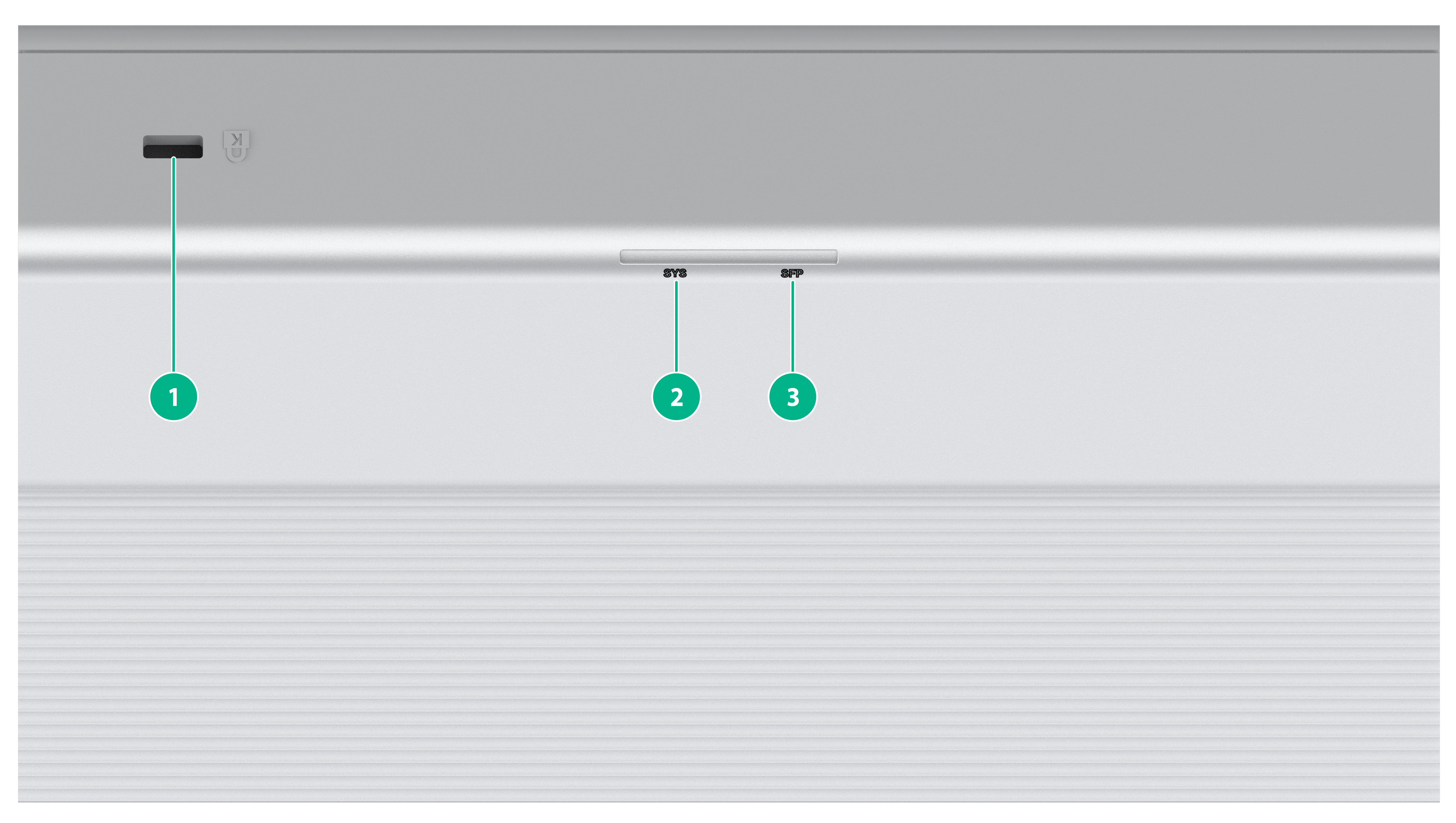
Figure 1 ES4200-2T1S-M panel (1)

|
(1) System LED (SYS) |
(2) SFP port LED |
|
(3) 10/100/1000BASE-T autosensing Ethernet port LED |
|
|
(4) 10/100/1000BASE-T autosensing Ethernet port |
|
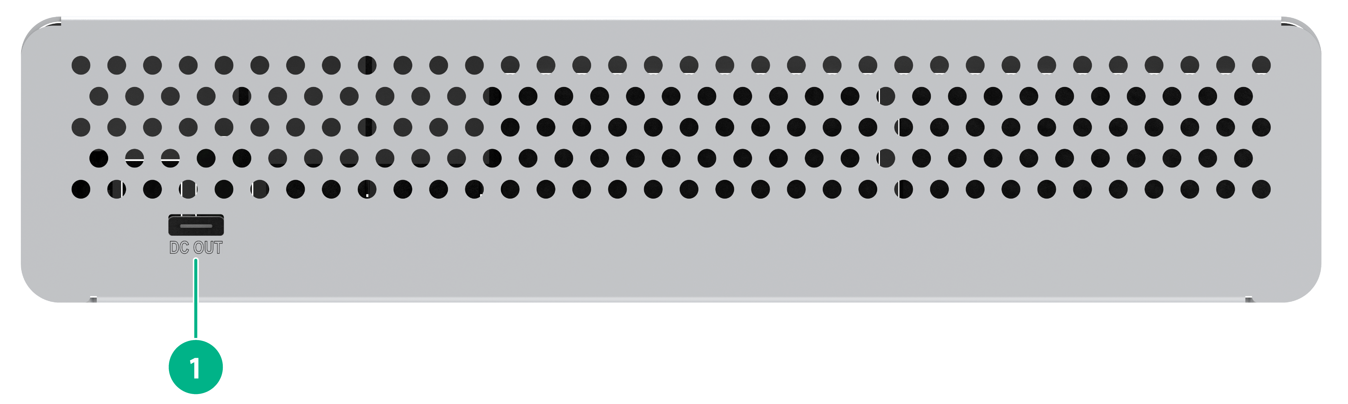
Figure 2 ES4200-2T1S-M panel (2)
|
(1) Type-C USB port |
(2) SFP port |
|
|
NOTE: The Type-C USB port is used for power supply only and does not support data transmission. |
Figure 3 ES4200-2T1S-M panel (3)
|
(1) RESET button |
ES4200-4T2ST
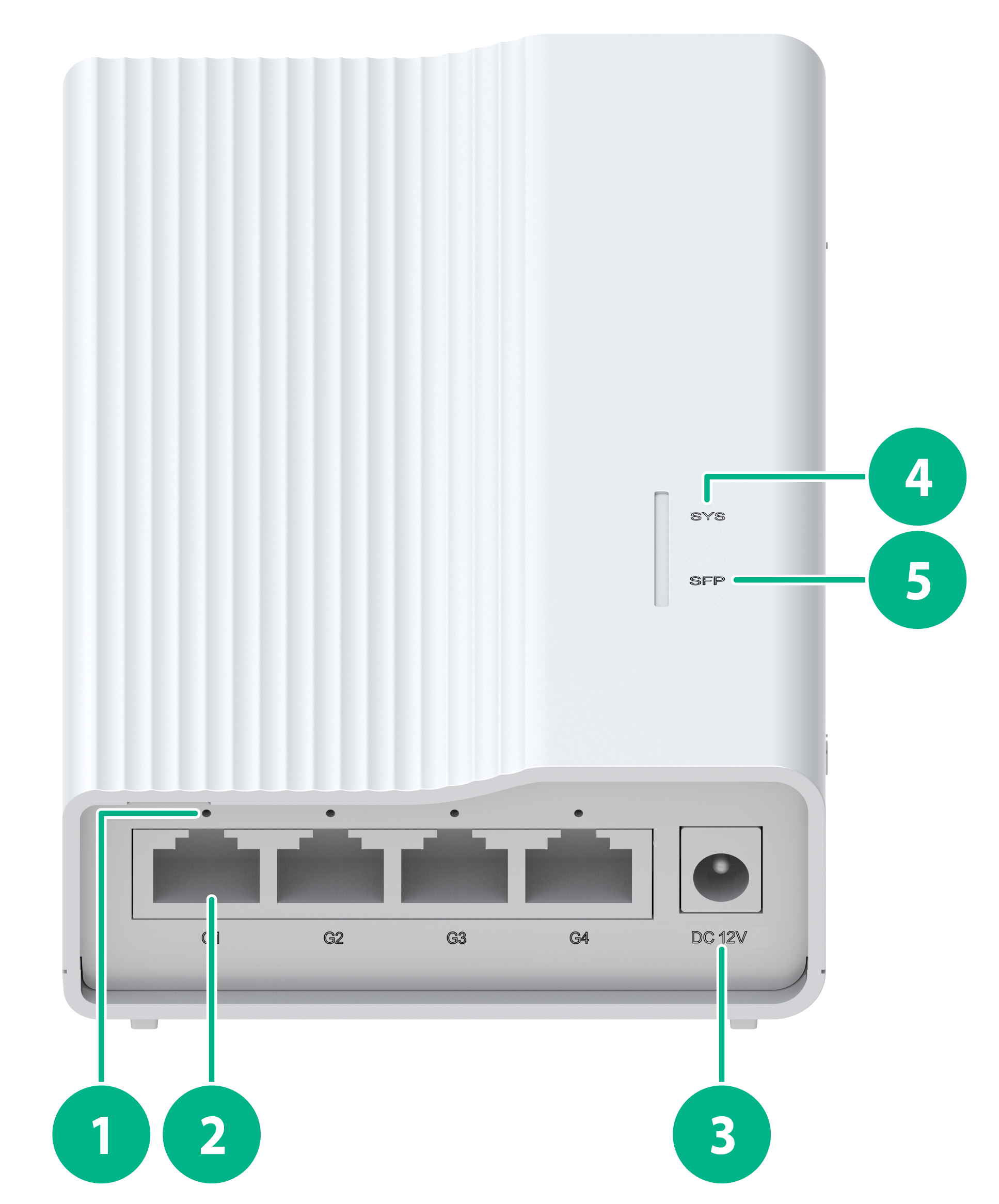
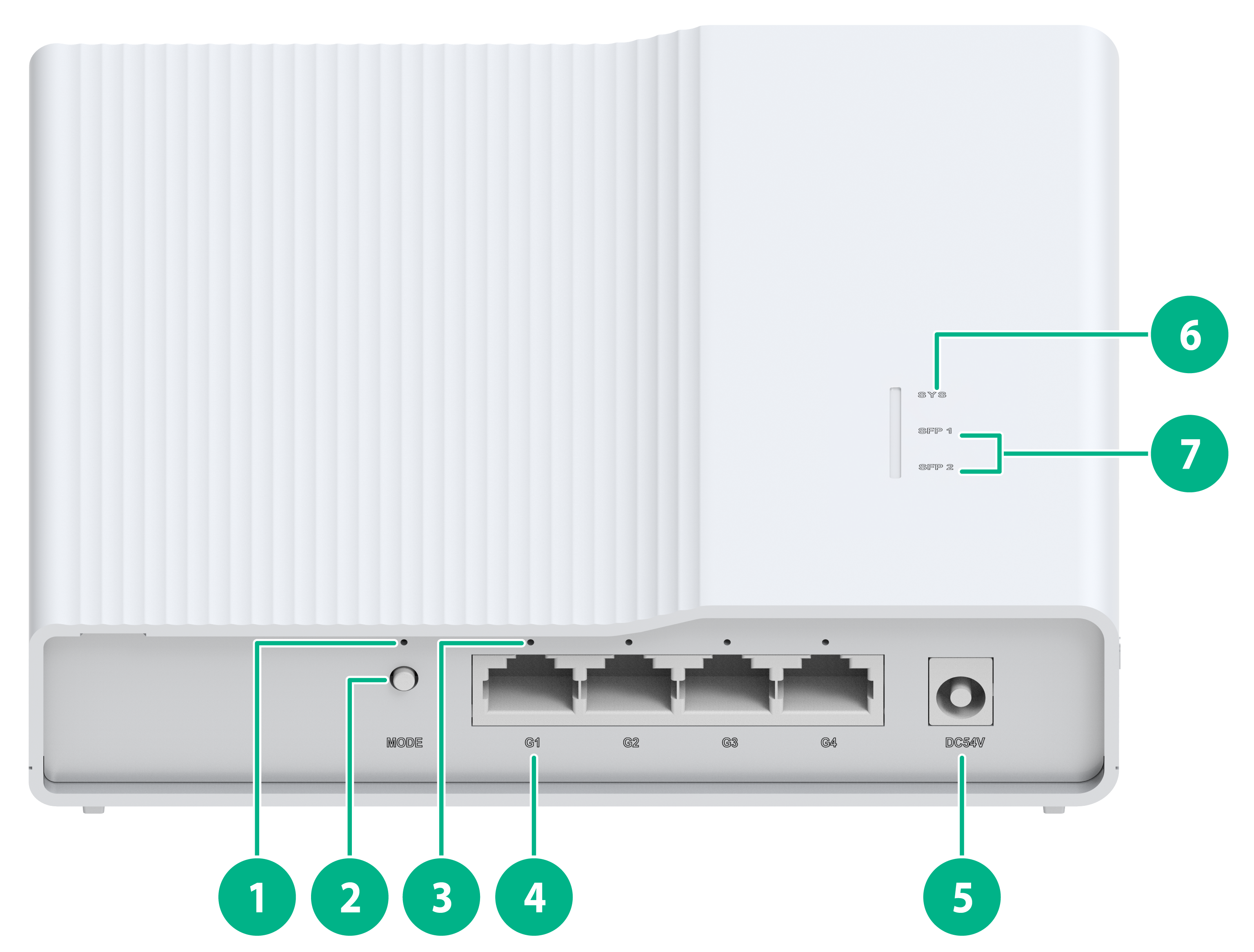
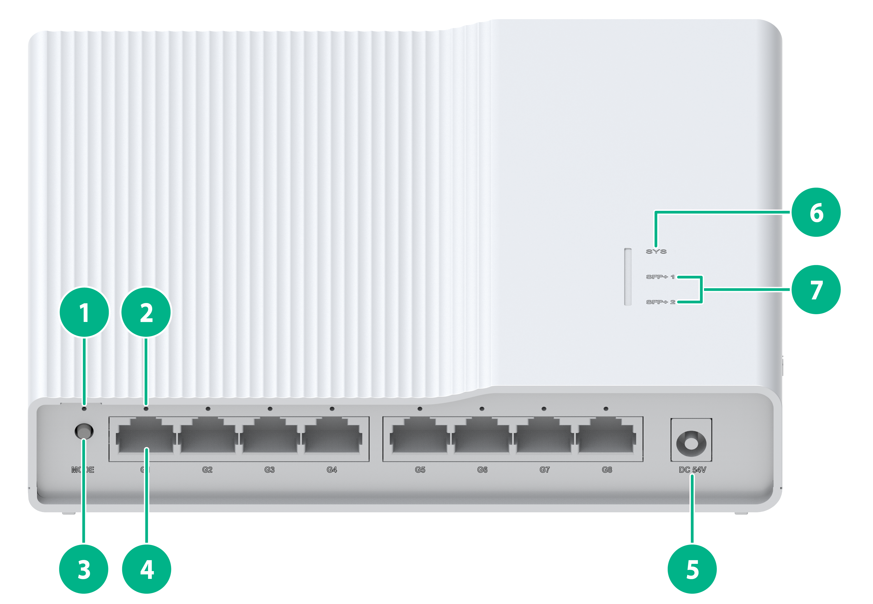
Figure 4 ES4200-4T2ST front panel
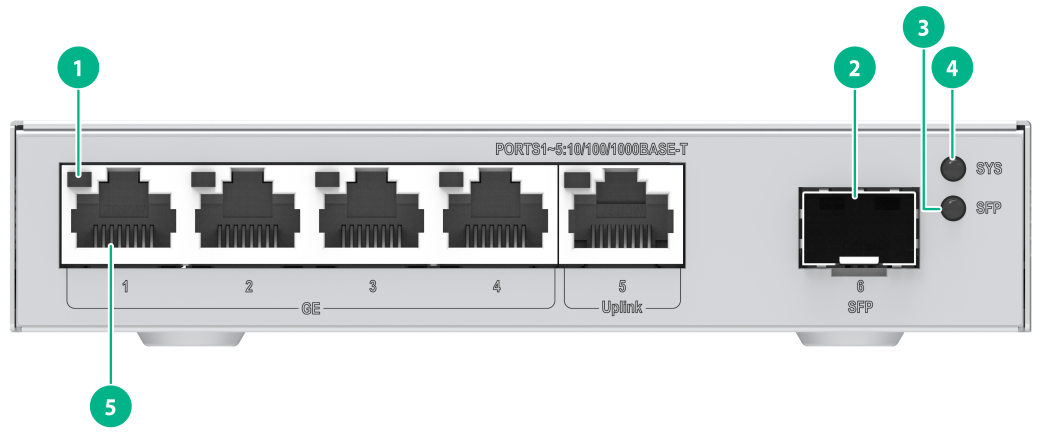
|
(1) 10/100/1000BASE-T autosensing Ethernet port LED |
(2) SFP port |
|
(3) SFP port LED |
(4) System LED (SYS) |
|
(5) 10/100/1000BASE-T autosensing Ethernet port |
|
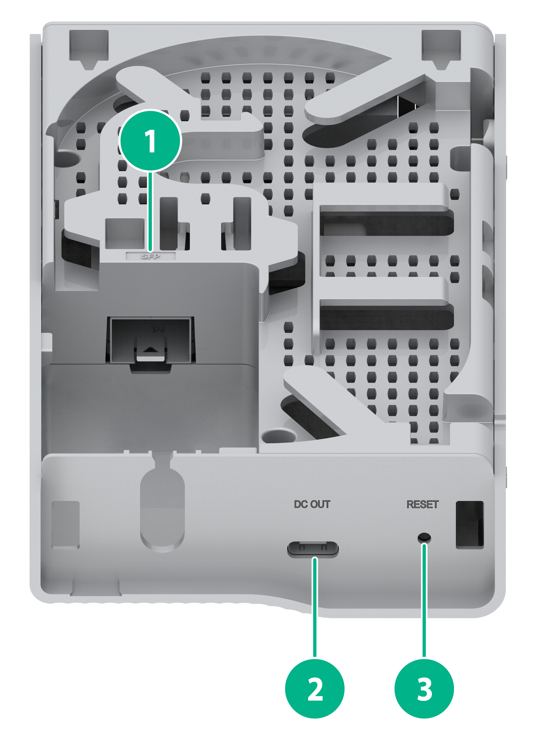
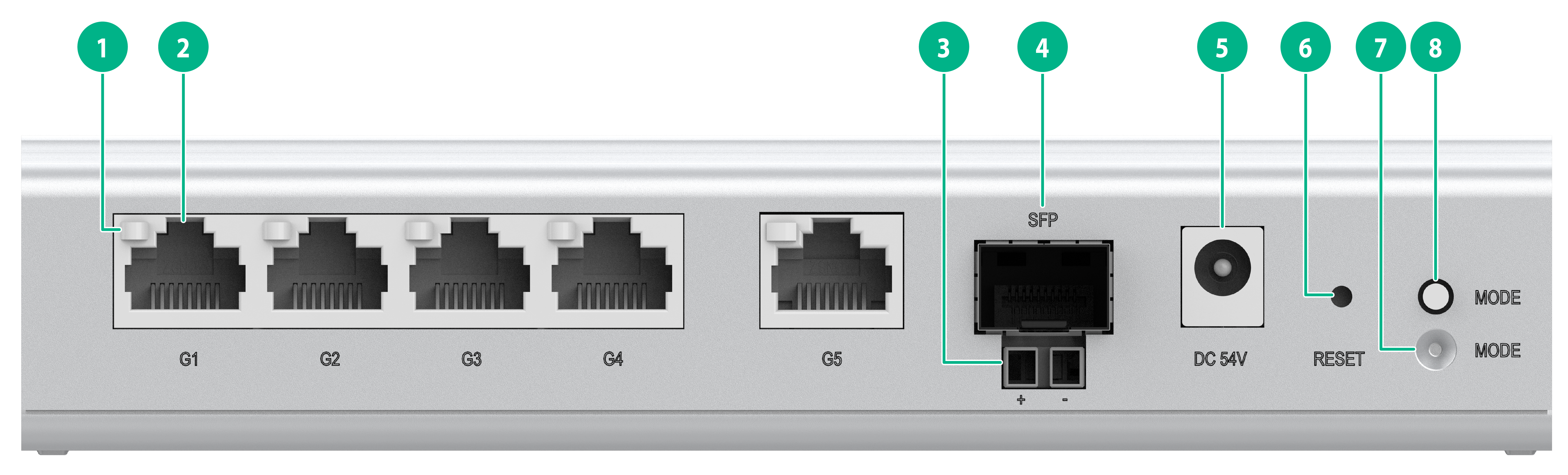
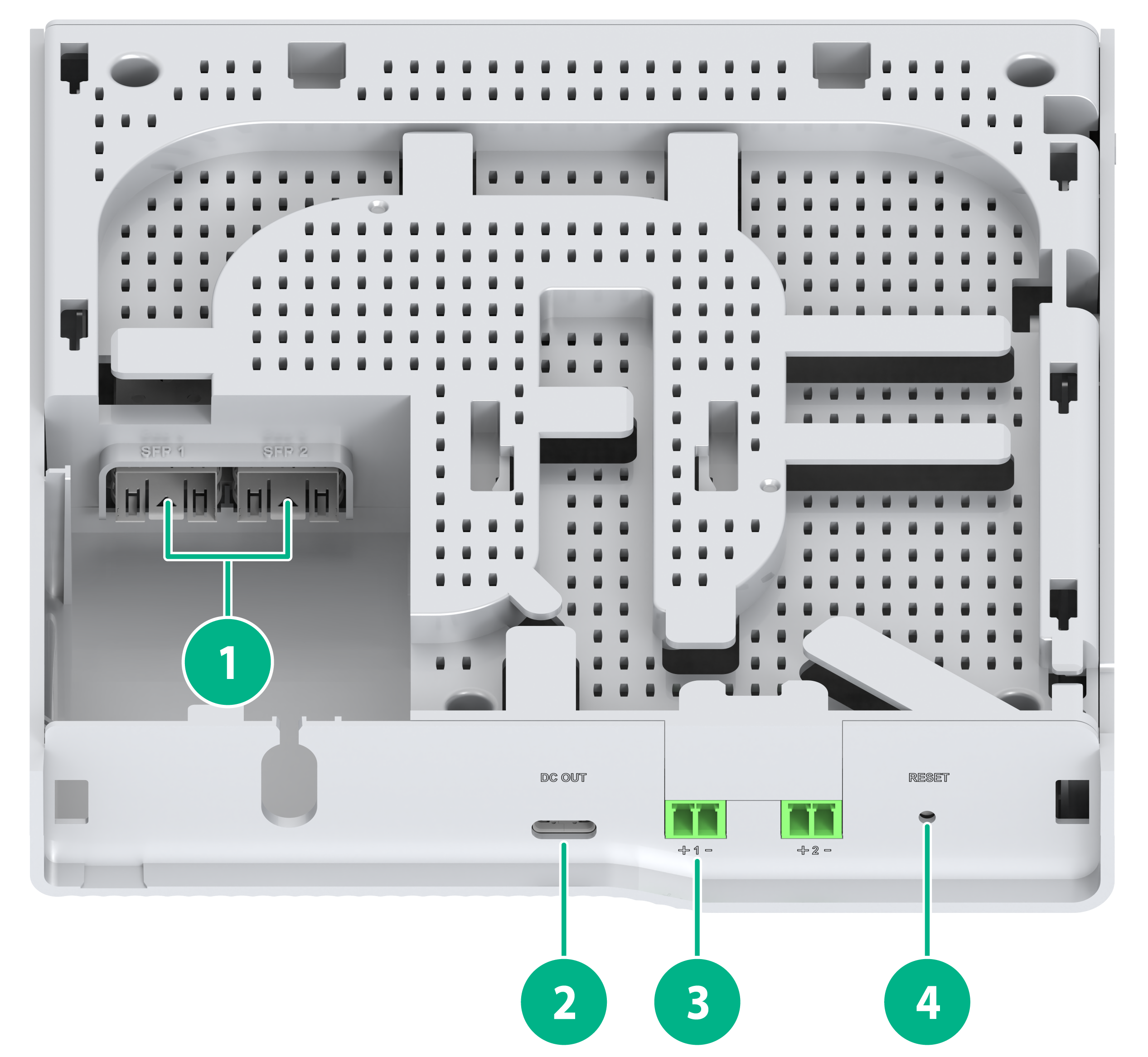
Figure 5 ES4200-4T2ST rear panel
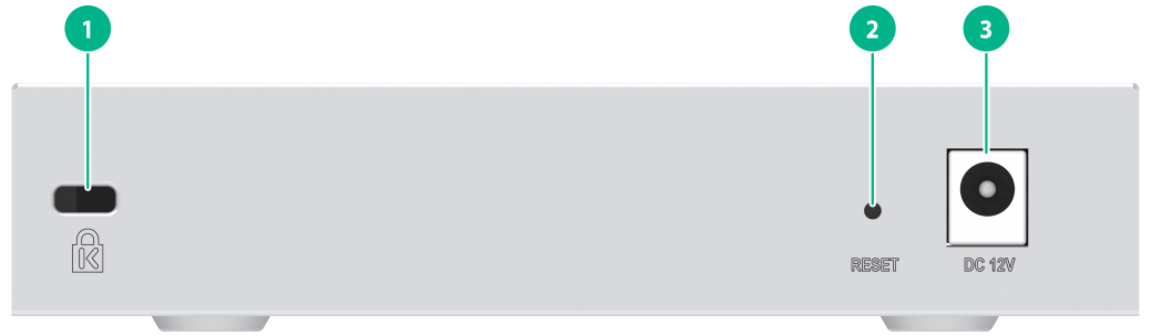
|
(1) Security slot |
(2) RESET button |
|
(3) Adapter input terminal |
|
|
|
NOTE: The methods for using the RESET button are as follows: · To restart the device, press the button and release the button when the SYS LED turns steady green. · To restore the default Web login password, press and hold the button for 1 to 5 seconds and release the button when the SYS LED flashes red slowly. · To restore the factory default and restart the device, press and hold the button for 5 to 10 seconds and release the button when the SYS LED flashes red rapidly. · If you press and hold the button for over 10 seconds and release the button when the SYS LED turns steady green, no action is performed. |
ES4200-8T2ST
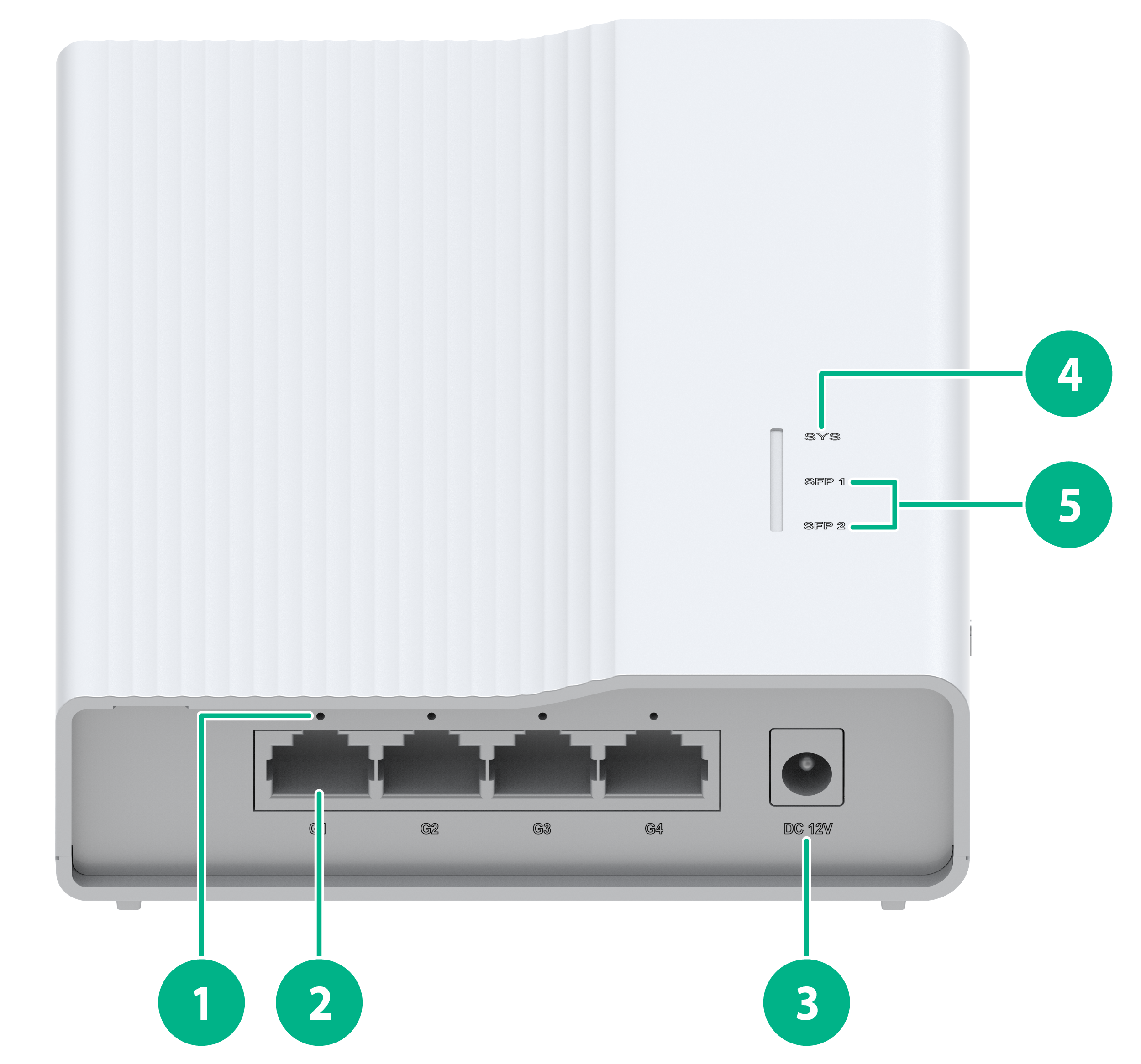
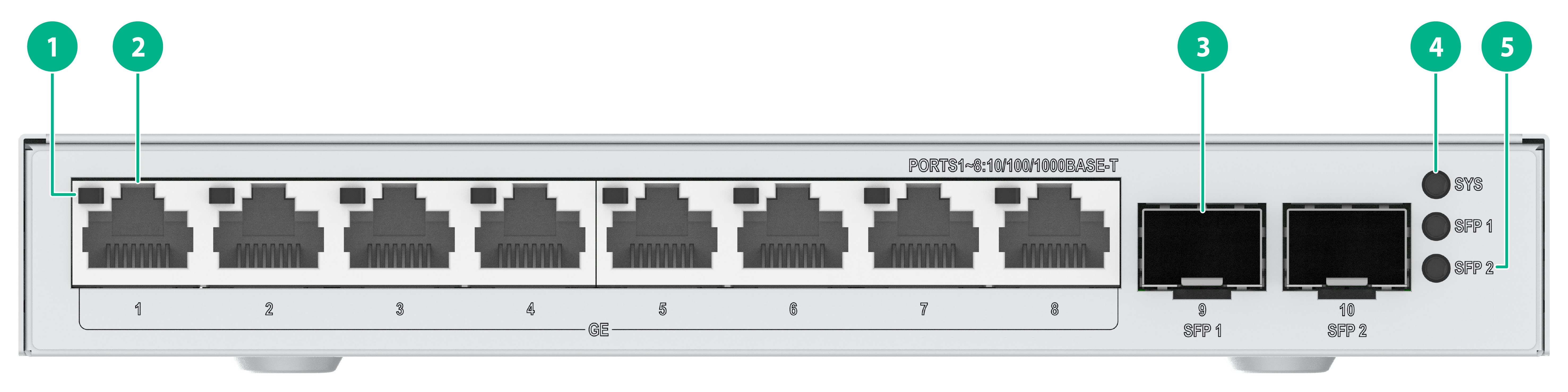
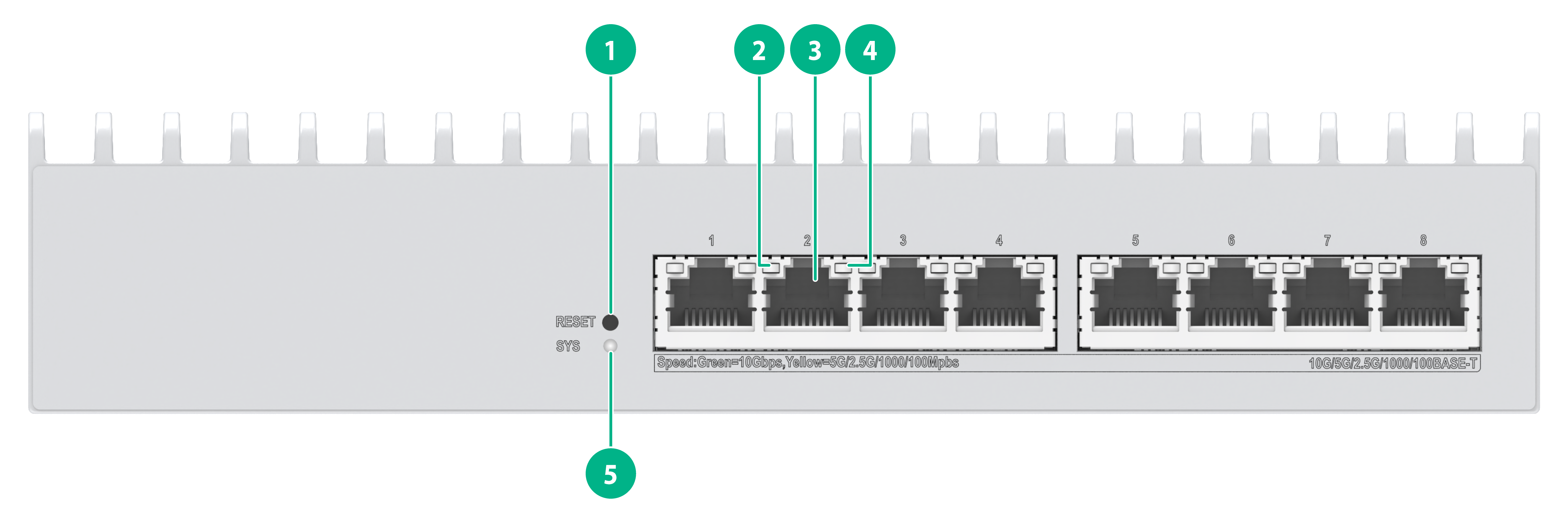
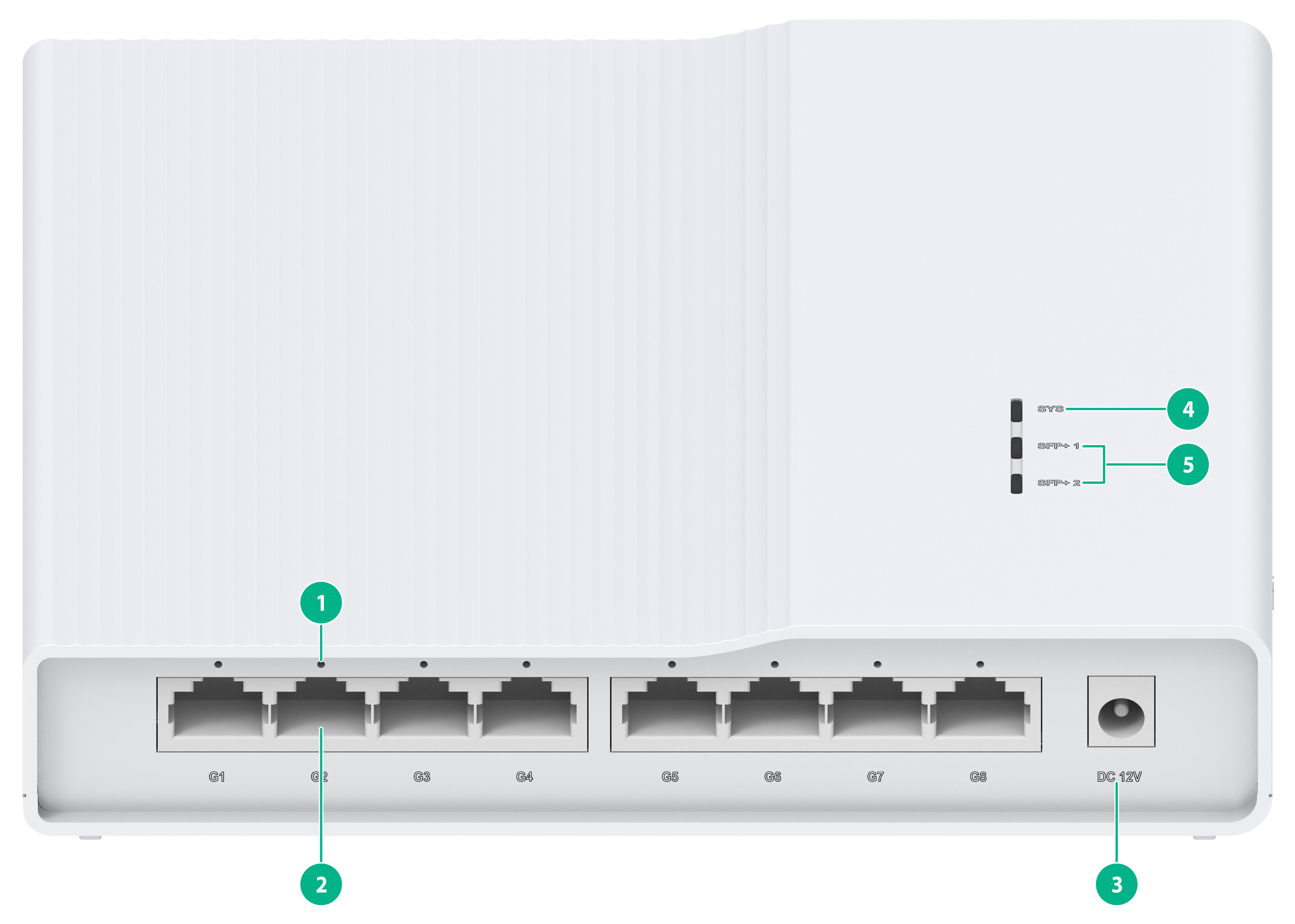
Figure 6 ES4200-8T2ST front panel
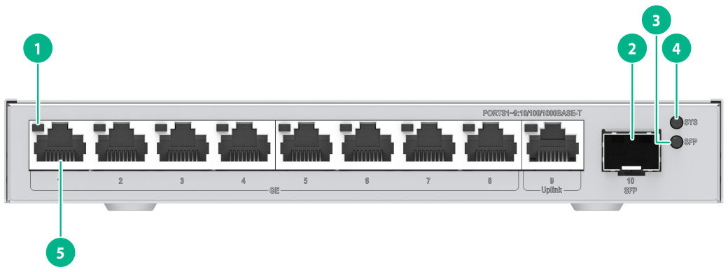
|
(1) 10/100/1000BASE-T autosensing Ethernet port LED |
(2) SFP port |
|
(3) SFP port LED |
(4) System LED (SYS) |
|
(5) 10/100/1000BASE-T autosensing Ethernet port |
|
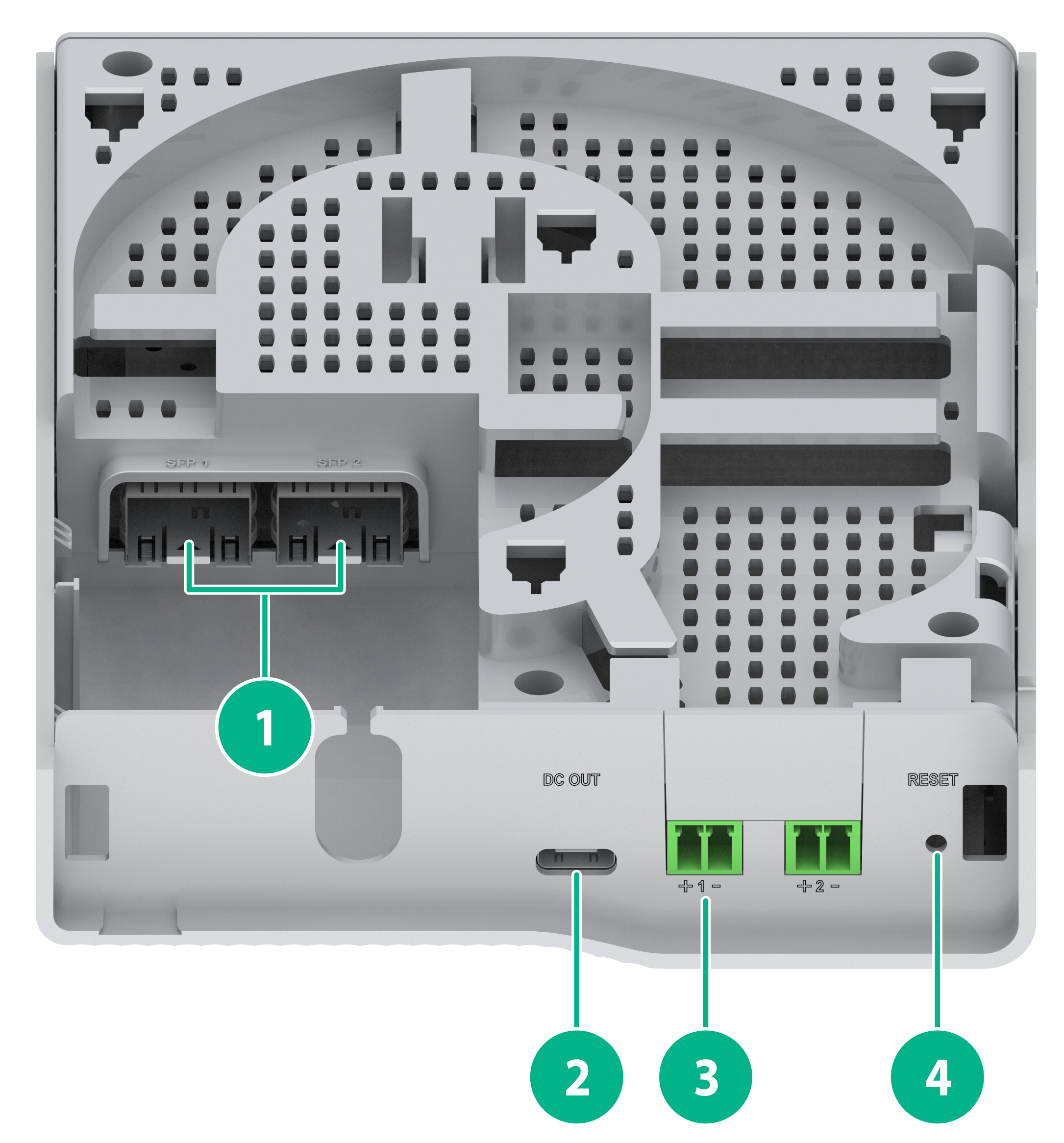
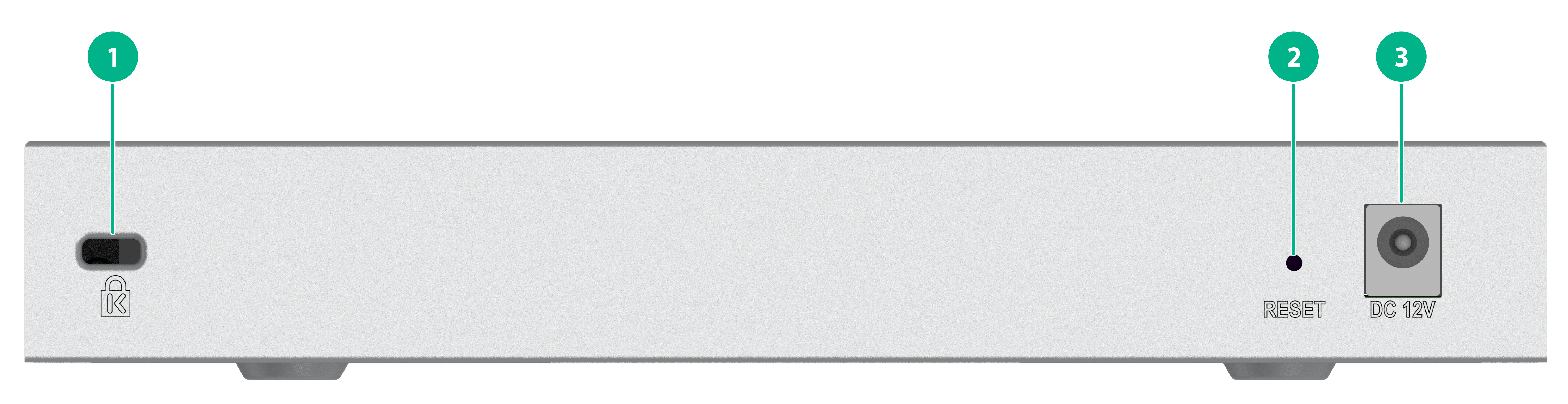
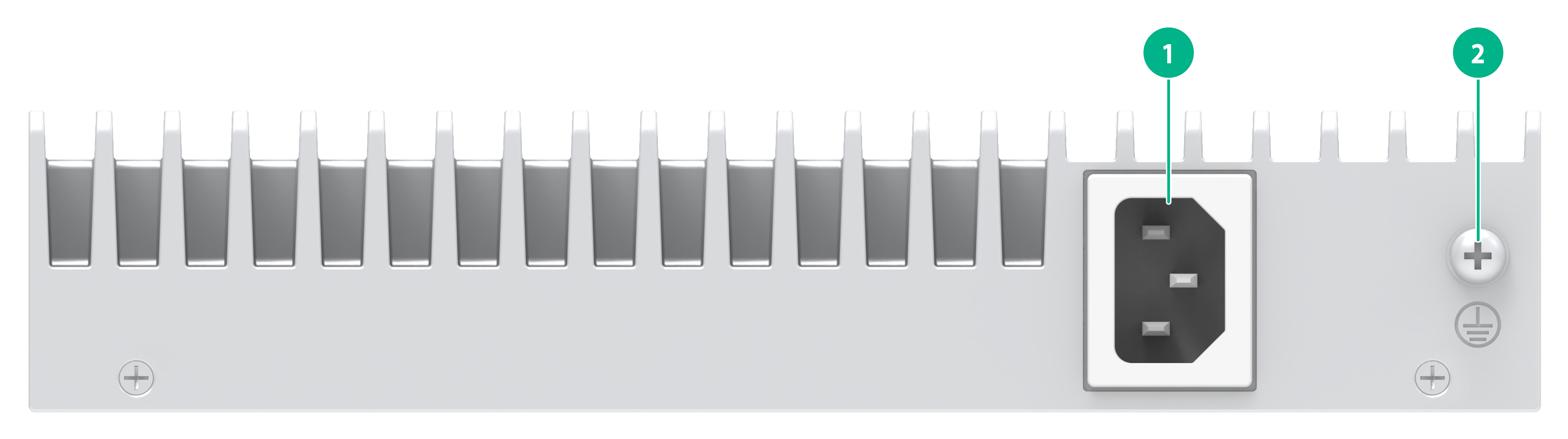
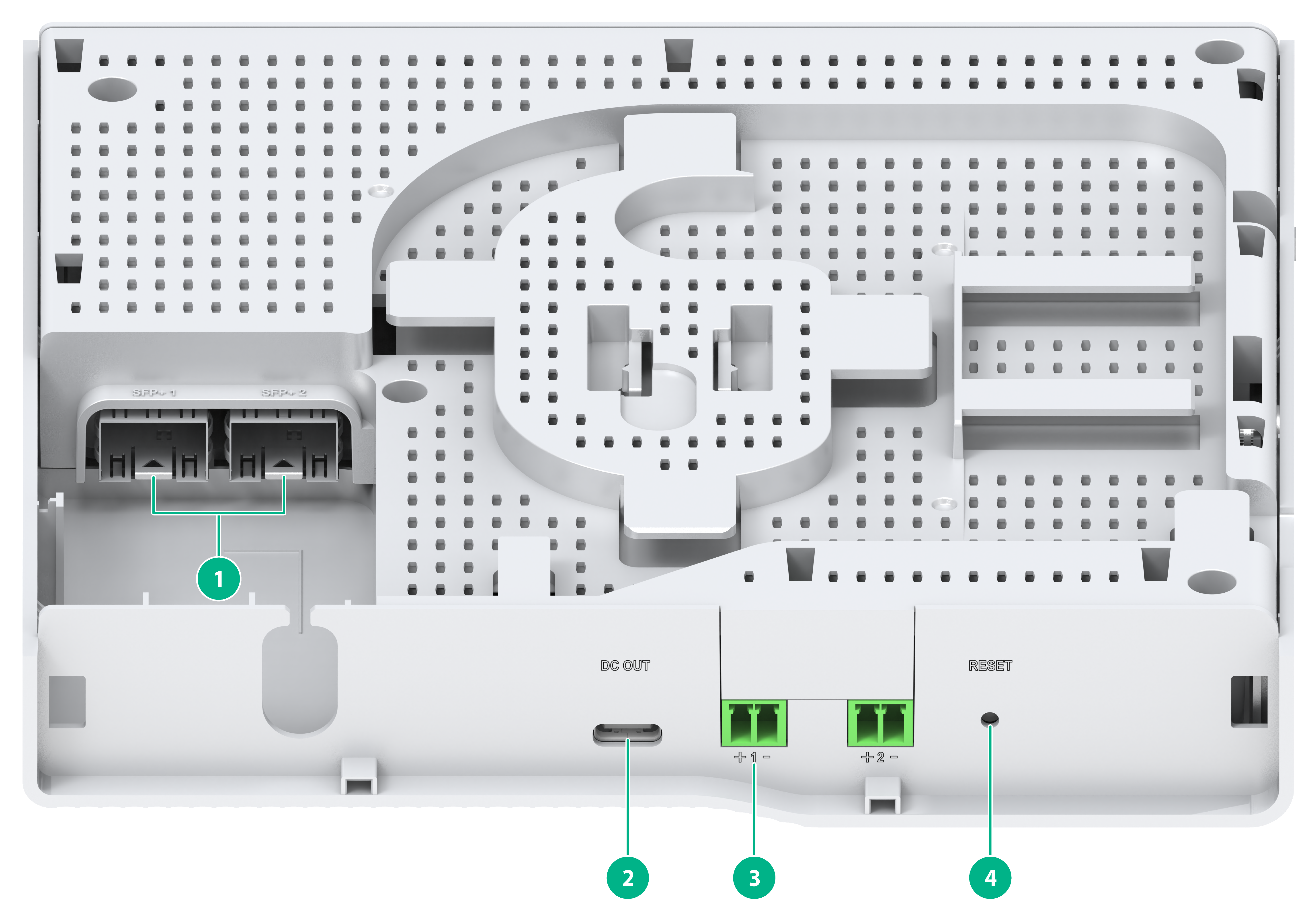
Figure 7 ES4200-8T2ST rear panel
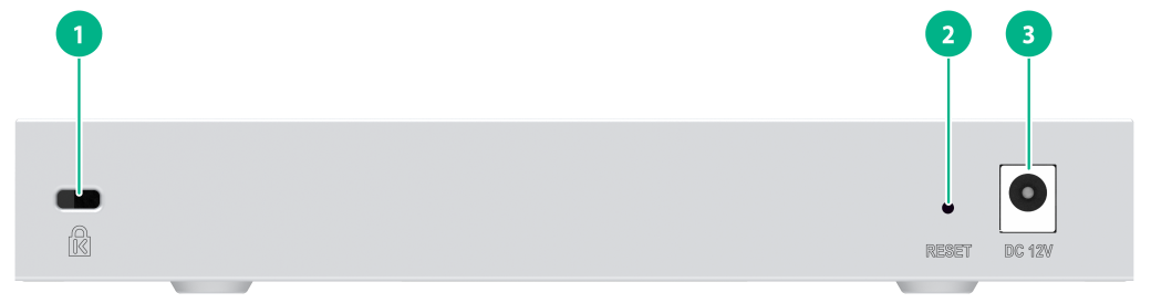
|
(1) Security slot |
(2) RESET button |
|
(3) Adapter input terminal |
|
|
|
NOTE: The methods for using the RESET button are as follows: · To restart the device, press the button and release the button when the SYS LED turns steady green. · To restore the default Web login password, press and hold the button for 1 to 5 seconds and release the button when the SYS LED flashes red slowly (1 Hz). · To restore the factory default and restart the device, press and hold the button for 5 to 10 seconds and release the button when the SYS LED flashes red rapidly (8 Hz). · If you press and hold the button for over 10 seconds and release the button when the SYS LED turns steady green, no action is performed. |
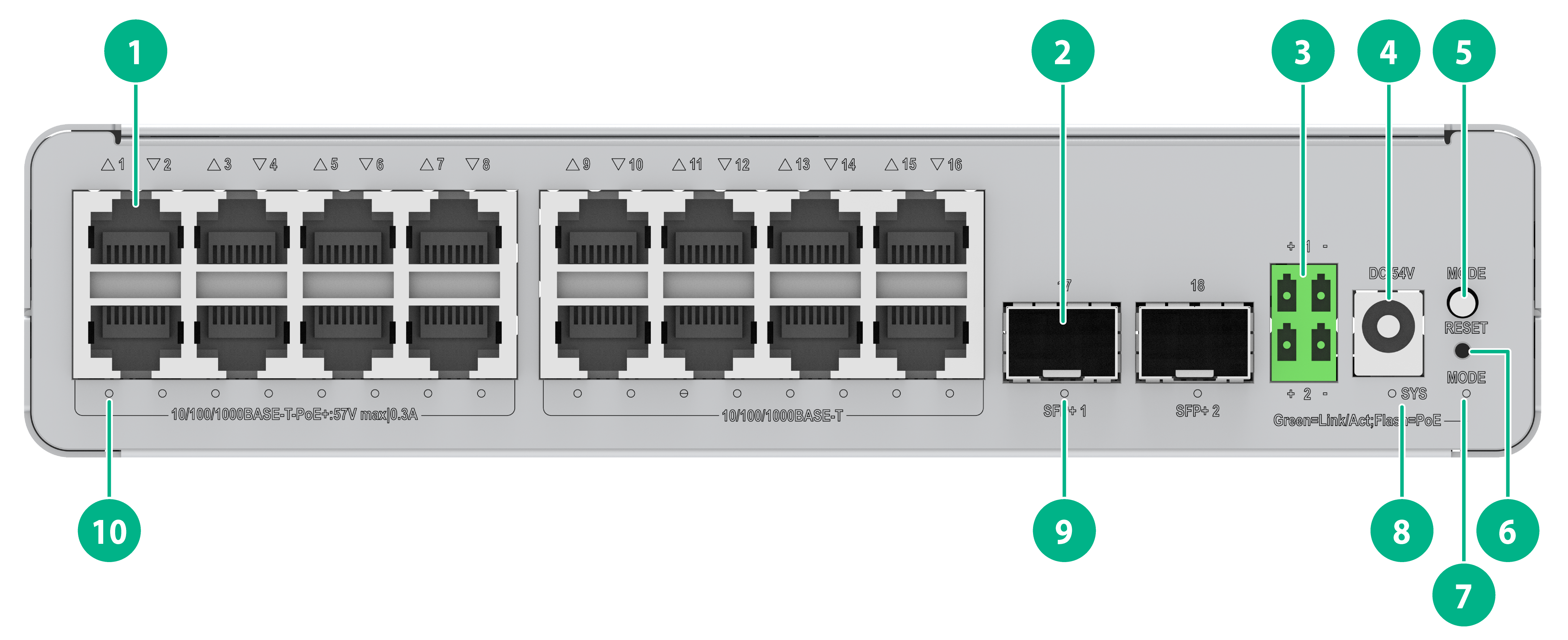
ES4200-8T2RS
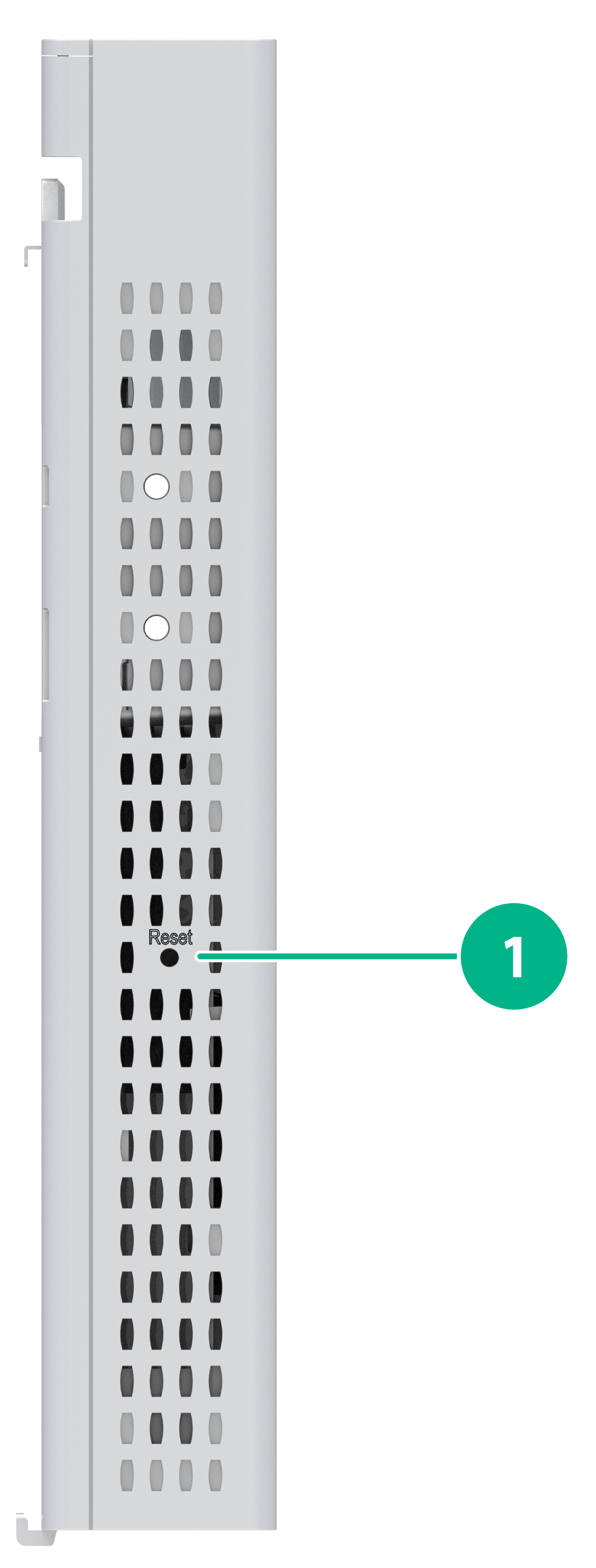
Figure 8 ES4200-8T2RS panel (1)
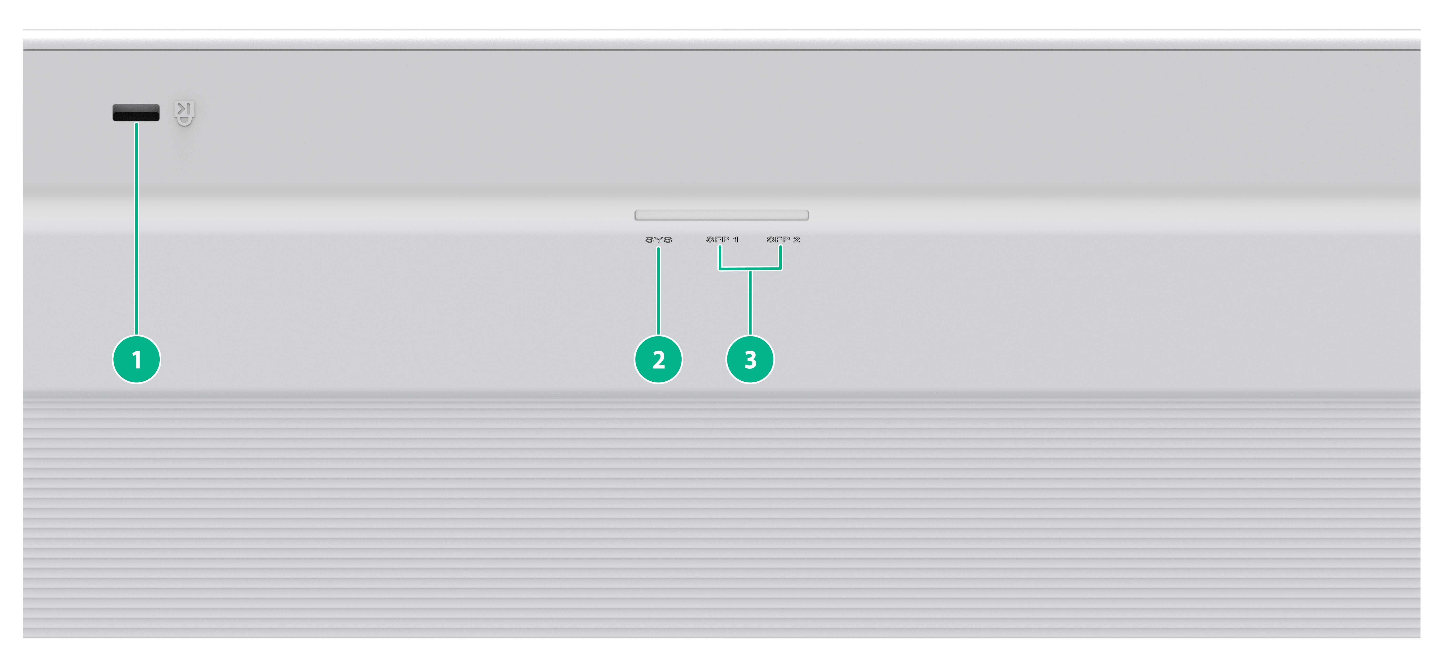
|
(1) Security slot |
(2) System LED (SYS) |
|
(3) SFP port LED |
|
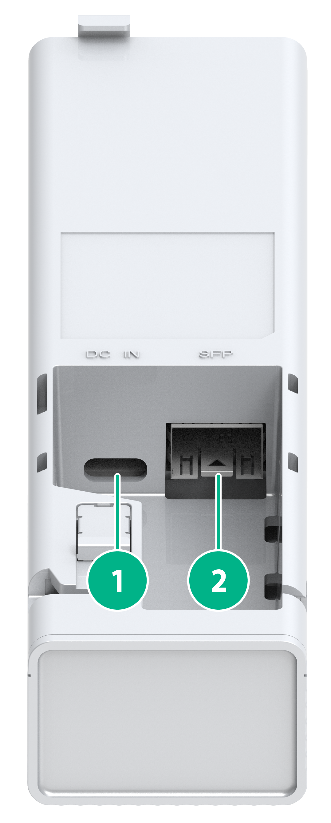
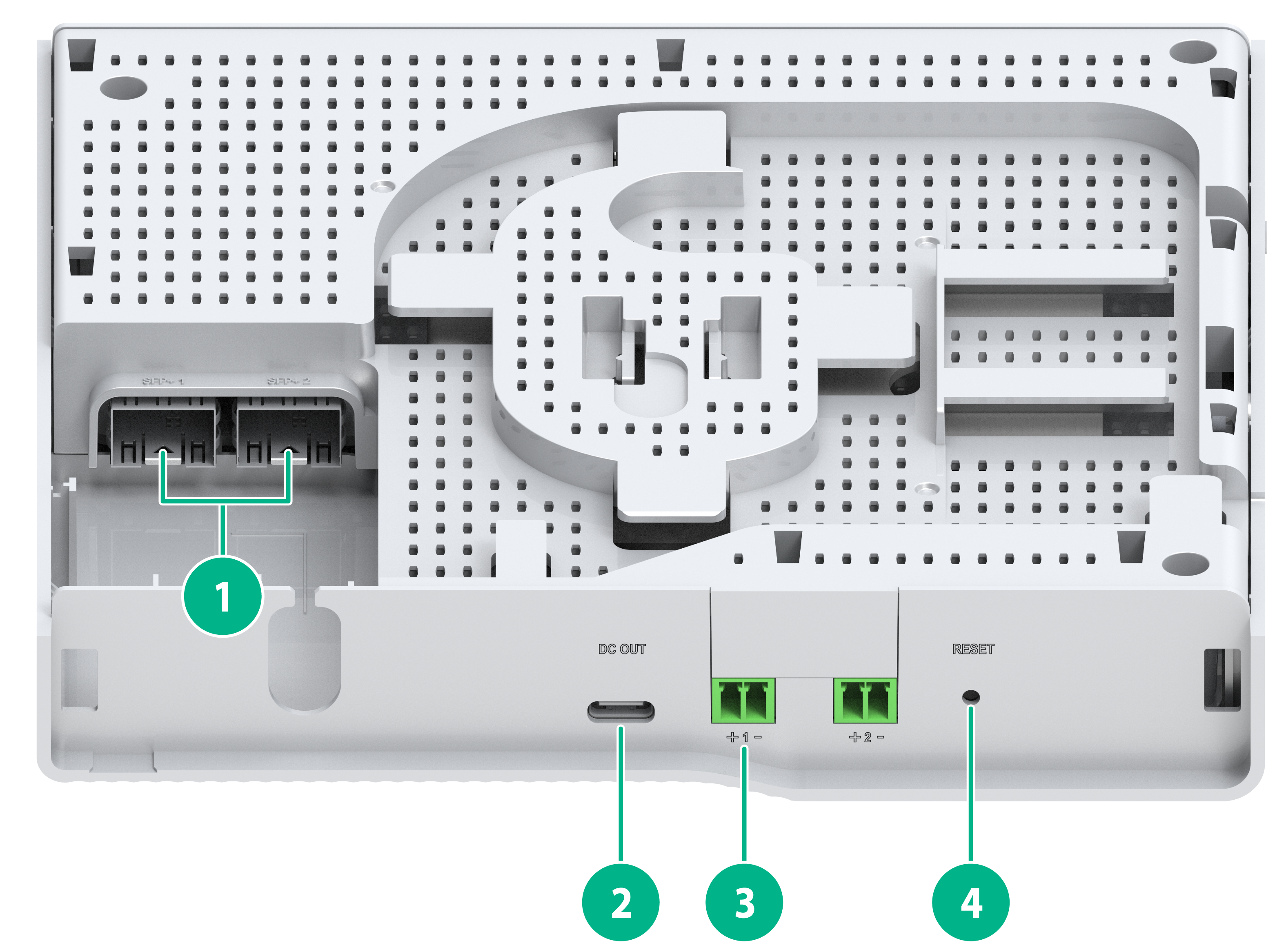
Figure 9 ES4200-8T2RS panel (2)
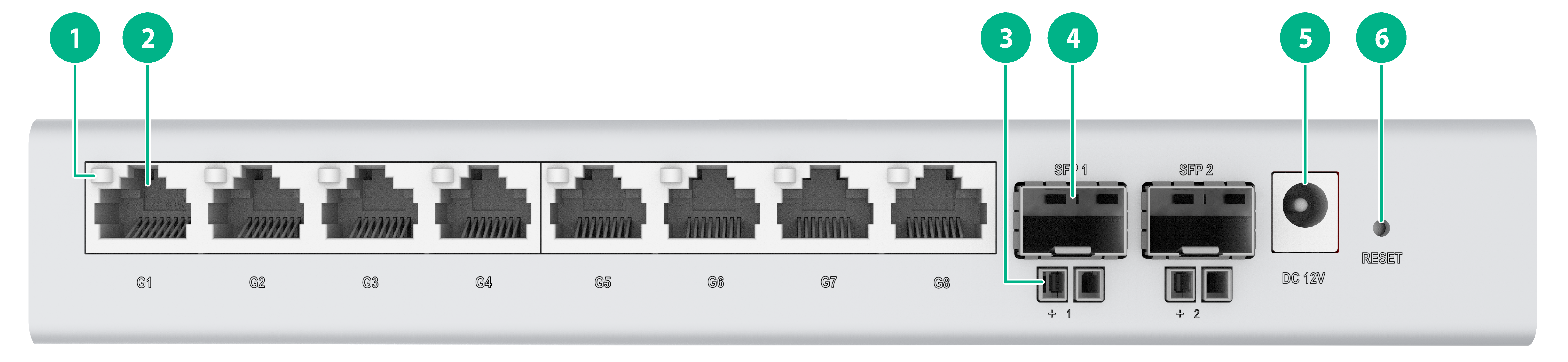
|
(1) 10/100/1000BASE-T autosensing Ethernet port LED |
|
|
(2) 10/100/1000BASE-T autosensing Ethernet port |
|
|
(3) PoE power receiving port |
(4) SFP port |
|
(5) Adapter input terminal |
(6) RESET button |
|
|
NOTE: · Each SFP port and the PoE port under it form a combined copper-fiber port. For a combined copper-fiber port to implement data and power transmission, it must be used together with an iOptic 3.0 transceiver module, a hybrid copper-fiber cable, and a combined fiber-copper pigtail. · A common LC transceiver module does not support working in conjunction with a combined copper-fiber port for data and power transmission unless a PoDLC connector is inserted into the module. |
|
|
NOTE: The methods for using the RESET button are as follows: · To restart the device, press the button and release the button when the SYS LED turns steady green. · To restore the default Web login password, press and hold the button for 1 to 5 seconds and release the button when the SYS LED flashes red slowly (1 Hz). · To restore the factory default and restart the device, press and hold the button for 5 to 10 seconds and release the button when the SYS LED flashes red rapidly (8 Hz). · If you press and hold the button for over 10 seconds and release the button when the SYS LED turns steady green, no action is performed. |
ES4200-4T1MS-B
Figure 10 ES4200-4T1MS-B panel (1)
|
(1) 10/100/1000BASE-T autosensing Ethernet port LED |
|
|
(2) 10/100/1000BASE-T autosensing Ethernet port |
|
|
(3) Adapter input terminal |
(4) System LED (SYS) |
|
(5) SFP port LED |
|
Figure 11 ES4200-4T1MS-B rear panel (2)
|
(1) SFP port |
(2) Type-C USB port |
|
(3) RESET button |
|
|
|
NOTE: The Type-C USB port is used for power supply only and does not support data transmission. |
|
|
NOTE: The methods for using the RESET button are as follows: · To restart the device, press the button and release the button when the SYS LED turns steady green. · To restore the default Web login password, press and hold the button for 1 to 5 seconds and release the button when the SYS LED flashes red slowly (1 Hz). · To restore the factory default and restart the device, press and hold the button for 5 to 10 seconds and release the button when the SYS LED flashes red rapidly (8 Hz). · If you press and hold the button for over 10 seconds and release the button when the SYS LED turns steady green, no action is performed. |
ES4200-4T2RMS-B
Figure 12 ES4200-4T2RMS-B panel (1)
|
(1) 10/100/1000BASE-T autosensing Ethernet port LED |
|
|
(2) 10/100/1000BASE-T autosensing Ethernet port |
|
|
(3) Adapter input terminal |
(4) System LED (SYS) |
|
(5) SFP port LED |
|
Figure 13 ES4200-4T2RMS-B panel (2)
|
(1) SFP port |
(2) Type-C USB port |
|
(3) PoE power receiving port |
(4) RESET button |
|
|
NOTE: The methods for using the RESET button are as follows: · To restart the device, press the button and release the button when the SYS LED turns steady green. · To restore the default Web login password, press and hold the button for 1 to 5 seconds and release the button when the SYS LED flashes red slowly (1 Hz). · To restore the factory default and restart the device, press and hold the button for 5 to 10 seconds and release the button when the SYS LED flashes red rapidly (8 Hz). · If you press and hold the button for over 10 seconds and release the button when the SYS LED turns steady green, no action is performed. |
ES4200-8T2S
Figure 14 ES4200-8T2S front panel
|
(1) 10/100/1000BASE-T autosensing Ethernet port LED |
(2) 10/100/1000BASE-T autosensing Ethernet port |
|
(3) SFP port |
(4) System LED (SYS) |
|
(5) SFP port LED |
|
Figure 15 ES4200-8T2S rear panel
|
(1) Security slot |
(2) RESET button |
|
(3) Adapter input terminal |
|
ES4200-16T2RX
Figure 16 ES4200-16T2RX front panel
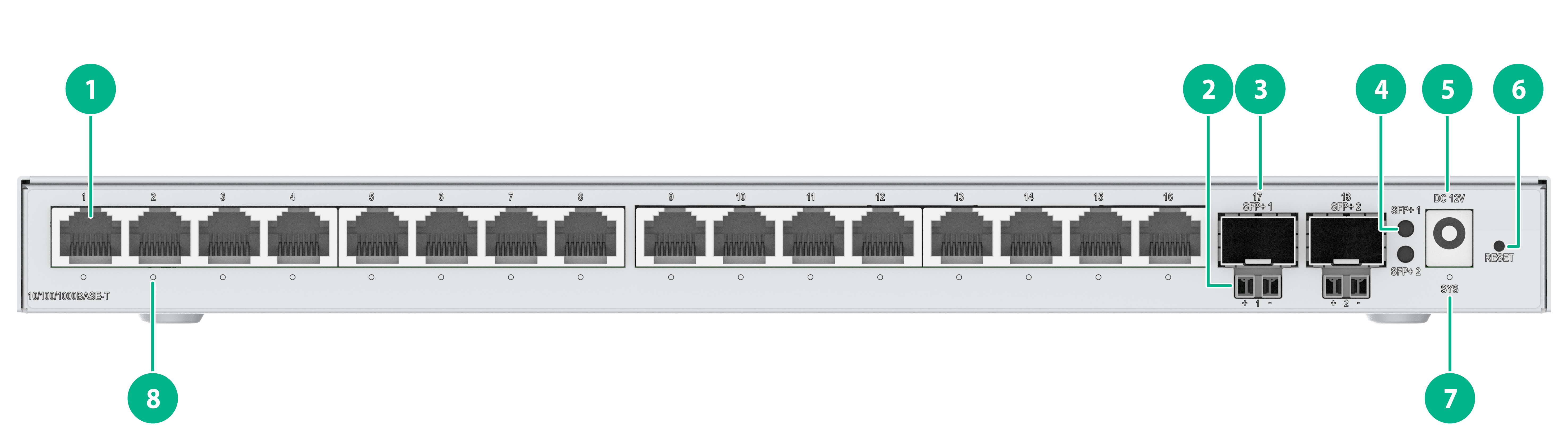
|
(1) 10/100/1000BASE-T autosensing Ethernet port |
(2) PoE power receiving port |
|
(3) SFP+ port |
(4) SFP+ port LED |
|
(5) Adapter input terminal |
(6) RESET button |
|
(7) System LED (SYS) |
(8) 10/100/1000BASE-T autosensing Ethernet port LED |
|
|
NOTE: · Each SFP+ port and the PoE port under it form a combined copper-fiber port. For a combined copper-fiber port to implement data and power transmission, it must be used together with an iOptic 3.0 transceiver module, a hybrid copper-fiber cable, and a combined fiber-copper pigtail. · A common LC transceiver module does not support working in conjunction with a combined copper-fiber port for data and power transmission unless a PoDLC connector is inserted into the module. |
|
|
NOTE: The methods for using the RESET button are as follows: · To restart the device, press the button and release the button when the SYS LED turns steady green. · To restore the default Web login password, press and hold the button for 1 to 5 seconds and release the button when the SYS LED flashes red slowly (1 Hz). · To restore the factory default and restart the device, press and hold the button for 5 to 10 seconds and release the button when the SYS LED flashes red rapidly (8 Hz). · If you press and hold the button for over 10 seconds and release the button when the SYS LED turns steady green, no action is performed. |
Figure 17 ES4200-16T2RX panel
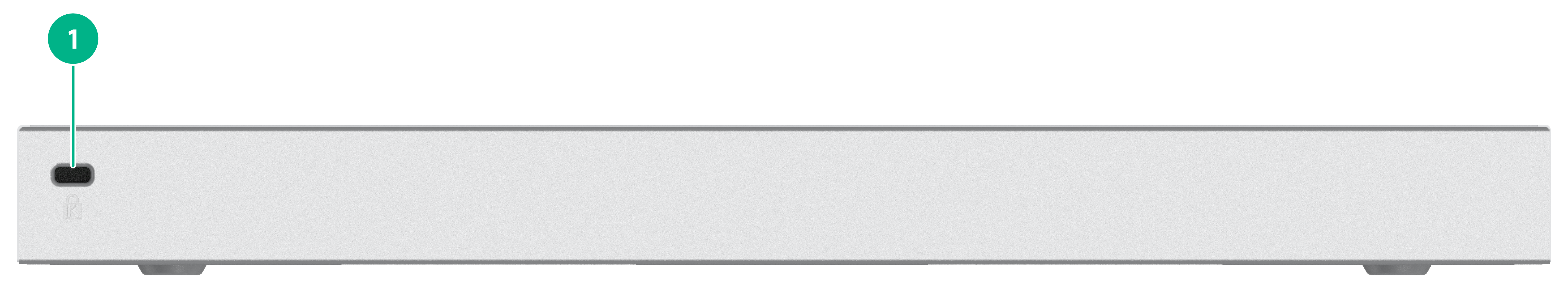
|
(1) Security slot |
ES4200-8MG
Figure 18 ES4200-8MG front panel
|
(1) RESET button |
(2) 10G/5G/2.5G/1000/100BASE-T autosensing Ethernet port LED (green) |
|
(3) 10G/5G/2.5G/1000/100BASE-T autosensing Ethernet port |
(4) 10G/5G/2.5G/1000/100BASE-T autosensing Ethernet port LED (yellow) |
|
(5) System LED (SYS) |
|
|
|
NOTE: The methods for using the RESET button are as follows: · To restart the device, press the button and release the button when the SYS LED turns steady green. · To restore the default Web login password, press and hold the button for 1 to 5 seconds and release the button when the SYS LED flashes red slowly (1 Hz). · To restore the factory default and restart the device, press and hold the button for 5 to 10 seconds and release the button when the SYS LED flashes red rapidly (8 Hz). · If you press and hold the button for over 10 seconds and release the button when the SYS LED turns steady green, no action is performed. |
Figure 19 ES4200-8MG rear panel
|
(1) AC power receptacle |
(2) Grounding screw |
ES4200-4UMG2X
Figure 20 ES4200-4UMG2X front panel
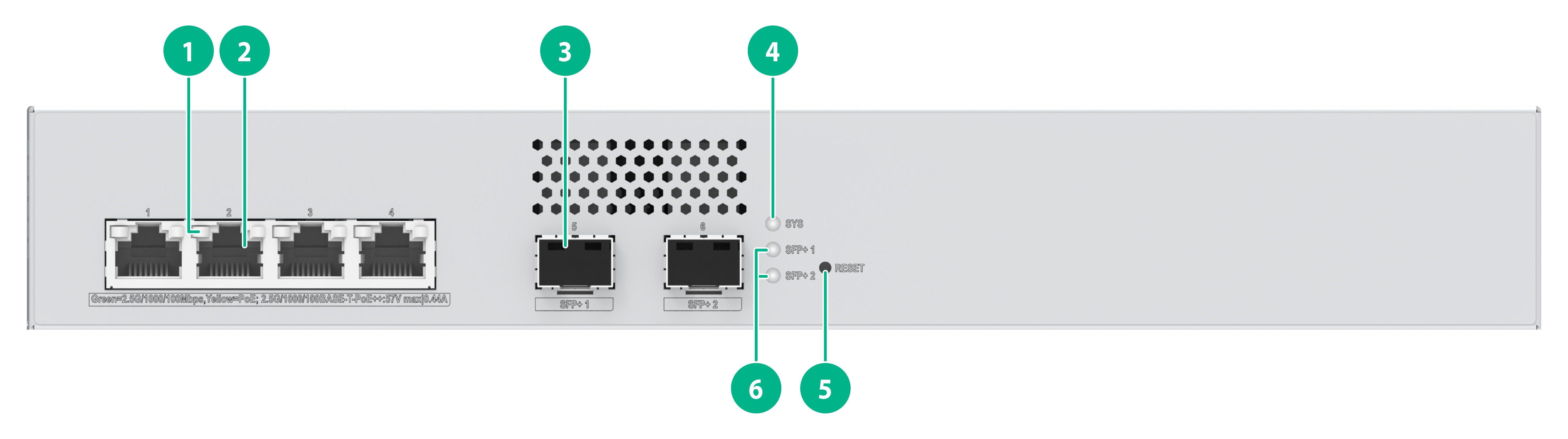
|
(1) 2.5G/1000/100BASE-T autosensing Ethernet port LED |
(2) 2.5G/1000/100BASE-T autosensing Ethernet port |
|
(3) SFP+ port |
(4) System LED (SYS) |
|
(5) RESET button |
(6) SFP+ port LED |
|
|
NOTE: The methods for using the RESET button are as follows: · To restart the device, press the button and release the button when the SYS LED turns steady green. · To restore the default Web login password, press and hold the button for 1 to 5 seconds and release the button when the SYS LED flashes red slowly (1 Hz). · To restore the factory default and restart the device, press and hold the button for 5 to 10 seconds and release the button when the SYS LED flashes red rapidly (8 Hz). · If you press and hold the button for over 10 seconds and release the button when the SYS LED turns steady green, no action is performed. |
Figure 21 ES4200-4UMG2X rear panel
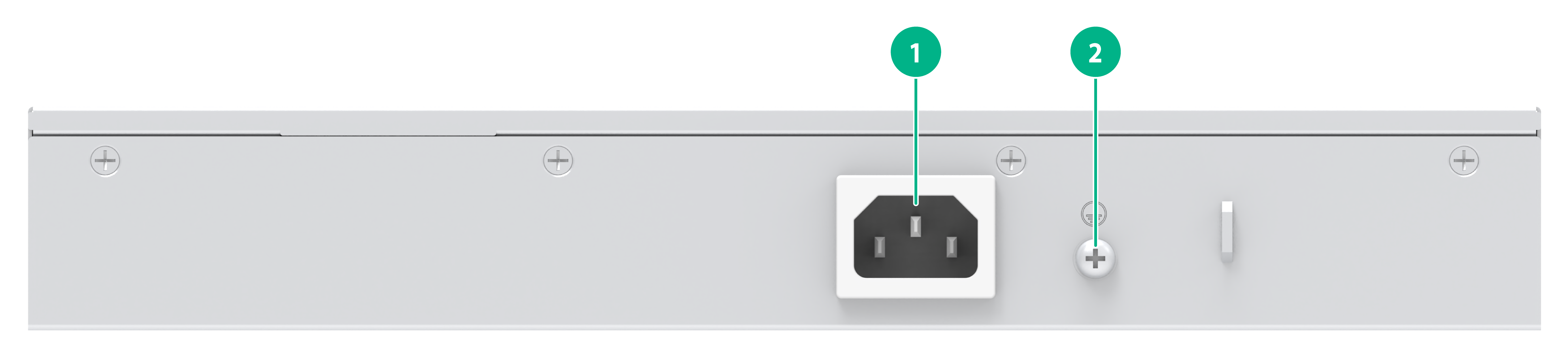
|
(1) AC power receptacle |
(2) Grounding screw |
ES4200-4P2ST
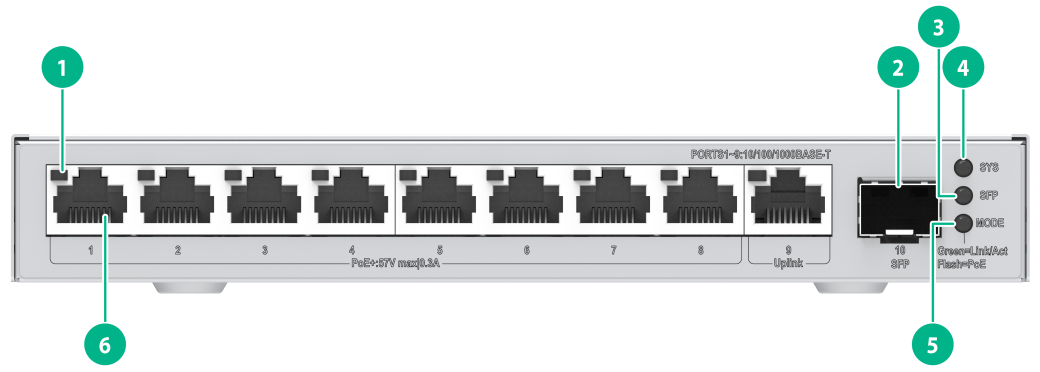
Figure 22 ES4200-4P2ST front panel
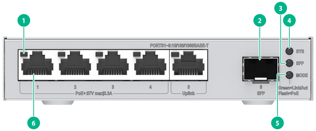
|
(1) 10/100/1000BASE-T autosensing Ethernet port LED |
|
|
(2) SFP port |
(3) SFP port LED |
|
(4) System LED (SYS) |
(5) Port mode LED (MODE) |
|
(6) 10/100/1000BASE-T autosensing Ethernet port |
|
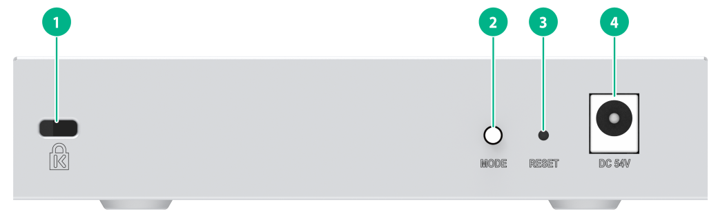
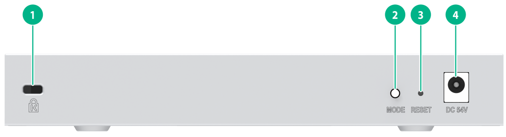
Figure 23 ES4200-4P2ST rear panel
|
(1) Security slot |
(2) Switch button for the port mode LED |
|
(3) RESET button |
(4) Adapter input terminal |
|
|
NOTE: The methods for using the RESET button are as follows: · To restart the device, press the button and release the button when the SYS LED turns steady green. · To restore the default Web login password, press and hold the button for 1 to 5 seconds and release the button when the SYS LED flashes red slowly (1 Hz). · To restore the factory default and restart the device, press and hold the button for 5 to 10 seconds and release the button when the SYS LED flashes red rapidly (8 Hz). · If you press and hold the button for over 10 seconds and release the button when the SYS LED turns steady green, no action is performed. |
ES4200-4P2RS
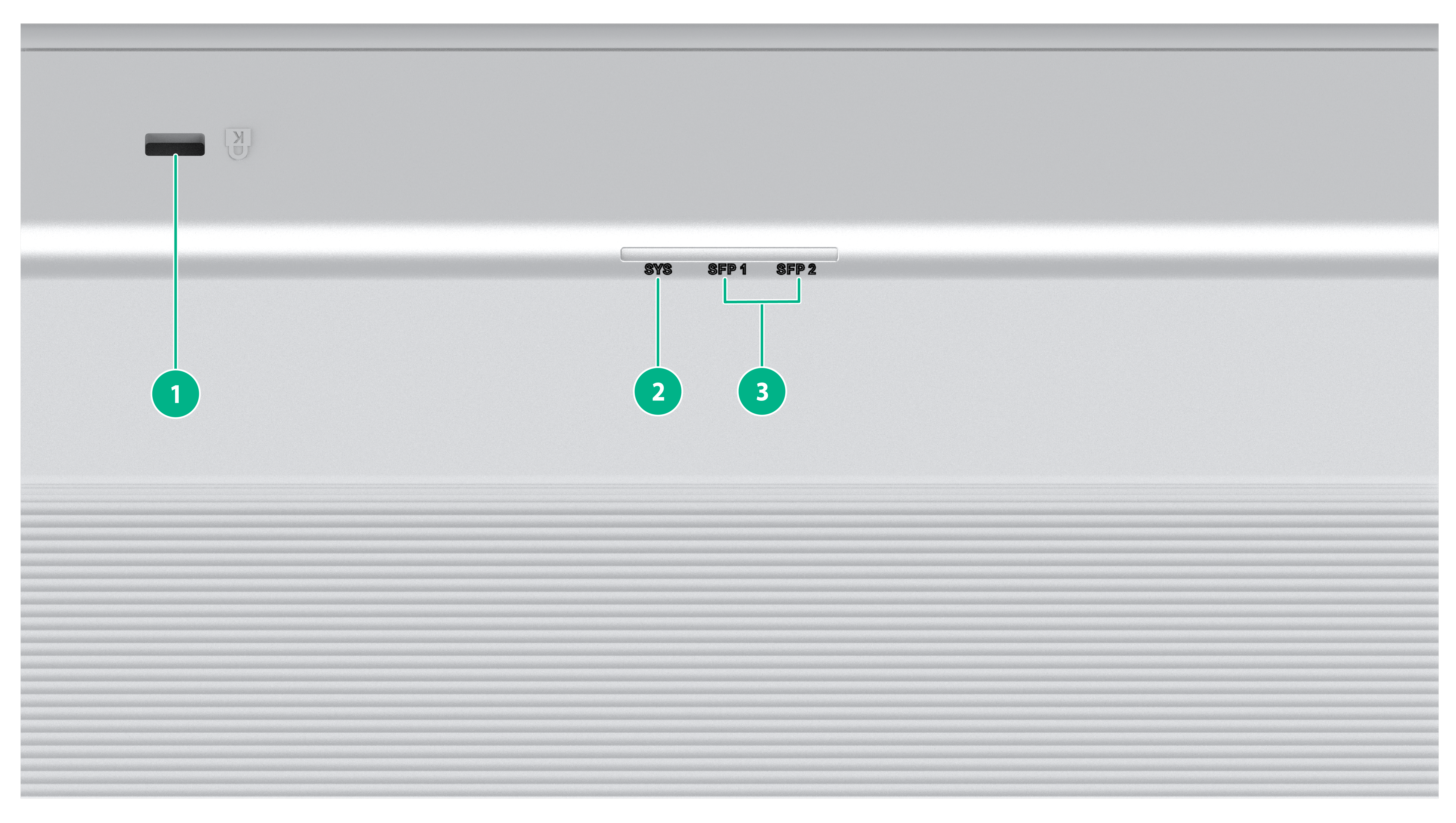
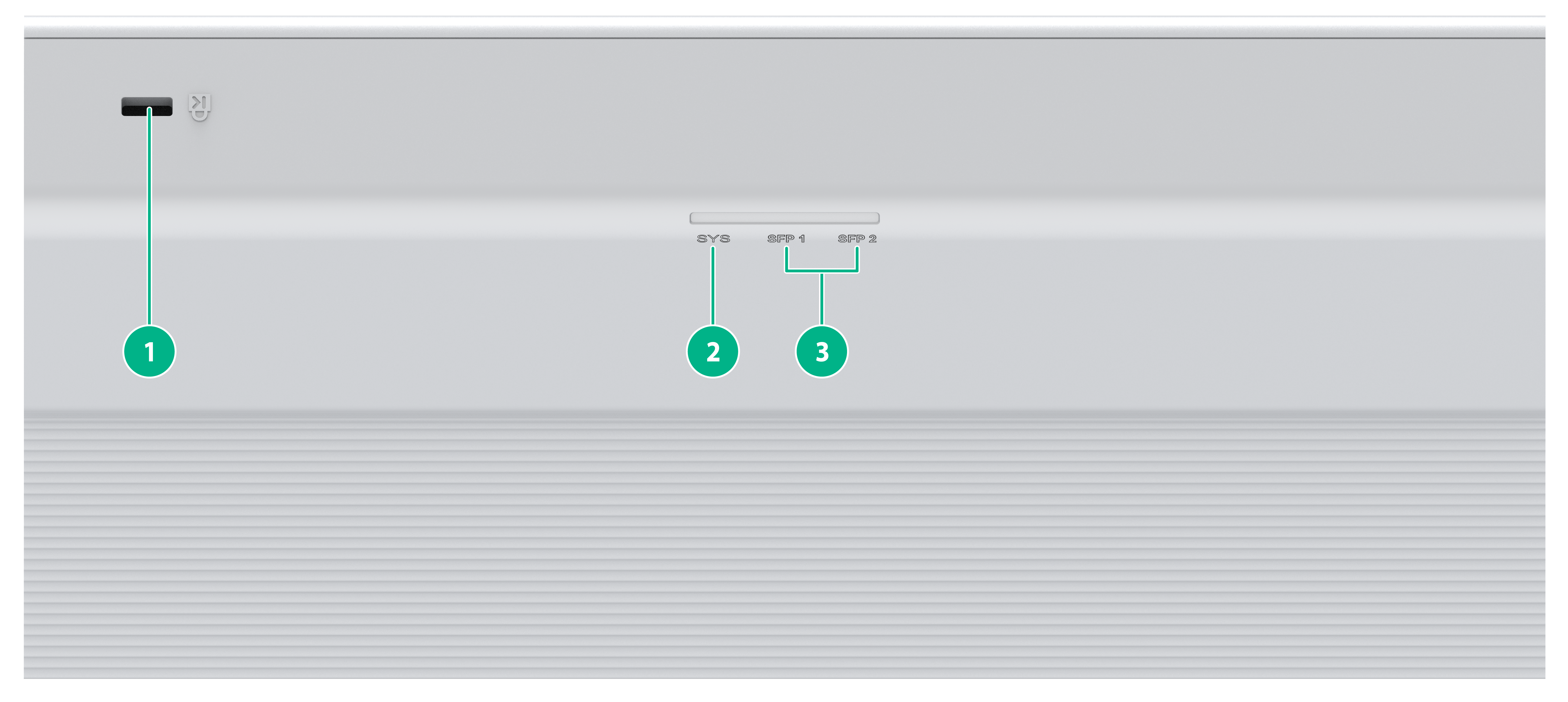
Figure 24 ES4200-4P2RS panel (1)
|
(1) Security slot |
(2) System LED (SYS) |
|
(3) SFP port LED |
|
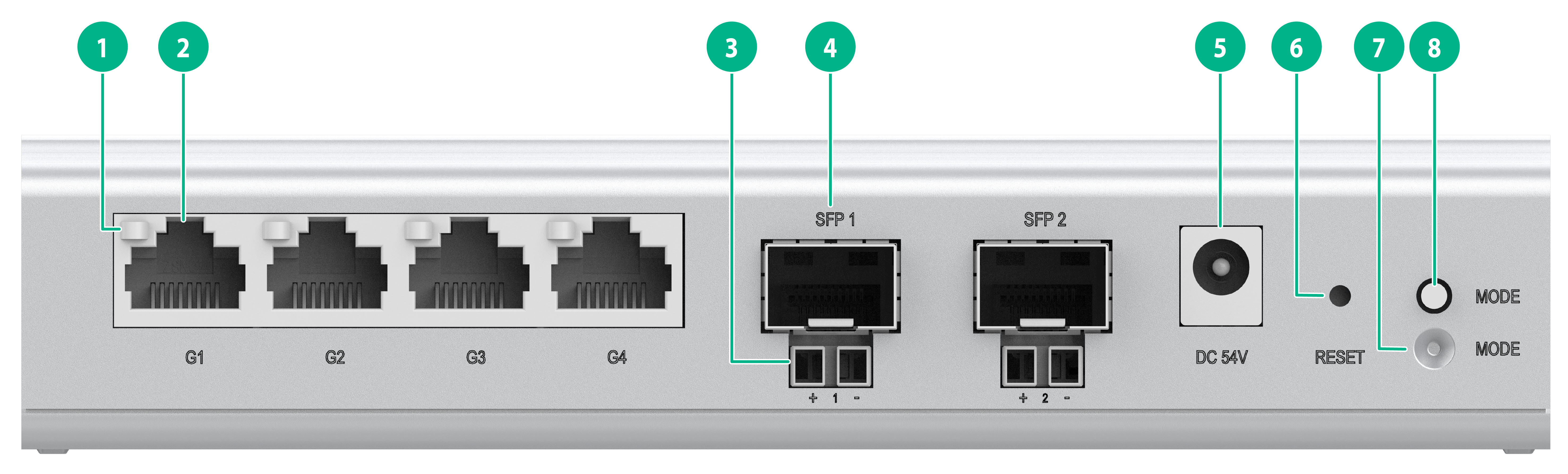
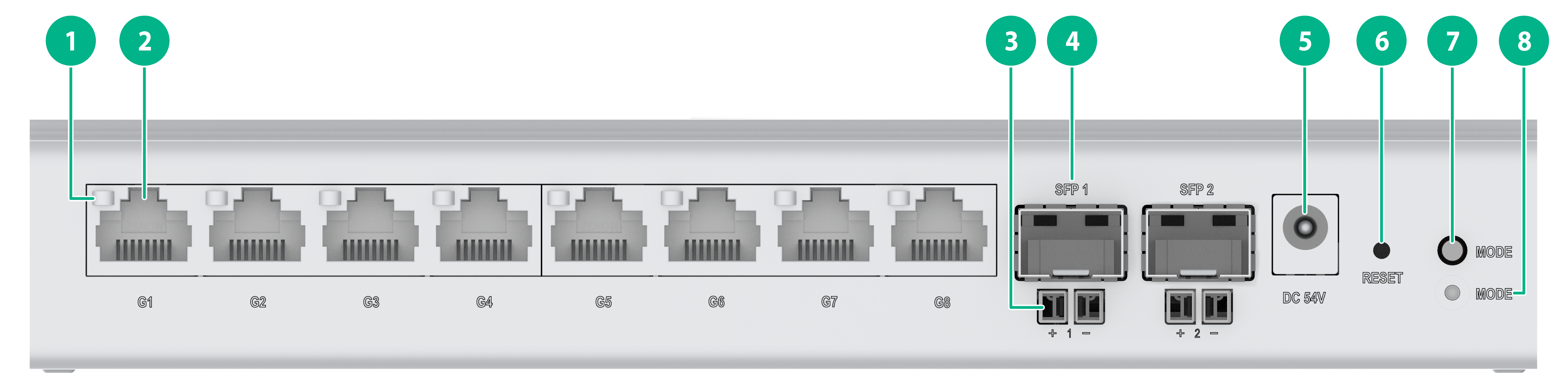
Figure 25 ES4200-4P2RS panel (2)
|
(1) 10/100/1000BASE-T autosensing Ethernet port LED |
|
|
(2) 10/100/1000BASE-T autosensing Ethernet port |
(3) PoE power receiving port |
|
(4) SFP port |
(5) Adapter input terminal |
|
(6) RESET button |
(7) Port mode LED (MODE) |
|
(8) Mode switch button for the port mode LED |
|
|
|
NOTE: · Each SFP port and the PoE port under it form a combined copper-fiber port. For a combined copper-fiber port to implement data and power transmission, it must be used together with an iOptic 3.0 transceiver module, a hybrid copper-fiber cable, and a combined fiber-copper pigtail. · A common LC transceiver module does not support working in conjunction with a combined copper-fiber port for data and power transmission unless a PoDLC connector is inserted into the module. |
|
|
NOTE: The methods for using the RESET button are as follows: · To restart the device, press the button and release the button when the SYS LED turns steady green. · To restore the default Web login password, press and hold the button for 1 to 5 seconds and release the button when the SYS LED flashes red slowly (1 Hz). · To restore the factory default and restart the device, press and hold the button for 5 to 10 seconds and release the button when the SYS LED flashes red rapidly (8 Hz). · If you press and hold the button for over 10 seconds and release the button when the SYS LED turns steady green, no action is performed. |
ES4200-4P2RST
Figure 26 ES4200-4P2RST panel (1)
|
(1) Security slot |
(2) System LED (SYS) |
|
(3) SFP port LED |
|
Figure 27 ES4200-4P2RST panel (2)
|
(1) 10/100/1000BASE-T autosensing Ethernet port LED |
|
|
(2) 10/100/1000BASE-T autosensing Ethernet port |
(3) PoE power receiving port |
|
(4) SFP port |
(5) Adapter input terminal |
|
(6) RESET button |
(7) Port mode LED (MODE) |
|
(8) Mode switch button for the port mode LED |
|
|
|
NOTE: · The SFP port and the PoE port under it form a combined copper-fiber port. For a combined copper-fiber port to implement data and power transmission, it must be used together with an iOptic 3.0 transceiver module, a hybrid copper-fiber cable, and a combined fiber-copper pigtail. · A common LC transceiver module does not support working in conjunction with a combined copper-fiber port for data and power transmission unless a PoDLC connector is inserted into the module. · Copper port numbered G5 supports power receiving over an Ethernet cable. |
|
|
NOTE: The methods for using the RESET button are as follows: · To restart the device, press the button and release the button when the SYS LED turns steady green. · To restore the default Web login password, press and hold the button for 1 to 5 seconds and release the button when the SYS LED flashes red slowly (1 Hz). · To restore the factory default and restart the device, press and hold the button for 5 to 10 seconds and release the button when the SYS LED flashes red rapidly (8 Hz). · If you press and hold the button for over 10 seconds and release the button when the SYS LED turns steady green, no action is performed. |
ES4200-8P2S
Figure 28 ES4200-8P2S front panel
|
(1) 10/100/1000BASE-T autosensing Ethernet port LED |
|
|
(2) 10/100/1000BASE-T autosensing Ethernet port |
(3) SFP port |
|
(4) SFP port LED |
(5) System LED (SYS) |
|
(6) Port mode LED (MODE) |
|
Figure 29 ES4200-8P2S rear panel
|
(1) Security slot |
(2) Mode switch button for the port mode LED |
|
(3) RESET button |
(4) Adapter input terminal |
|
|
NOTE: The methods for using the RESET button are as follows: · To restart the device, press the button and release the button when the SYS LED turns steady green. · To restore the default Web login password, press and hold the button for 1 to 5 seconds and release the button when the SYS LED flashes red slowly (1 Hz). · To restore the factory default and restart the device, press and hold the button for 5 to 10 seconds and release the button when the SYS LED flashes red rapidly (8 Hz). · If you press and hold the button for over 10 seconds and release the button when the SYS LED turns steady green, no action is performed. |
ES4200-8P2ST
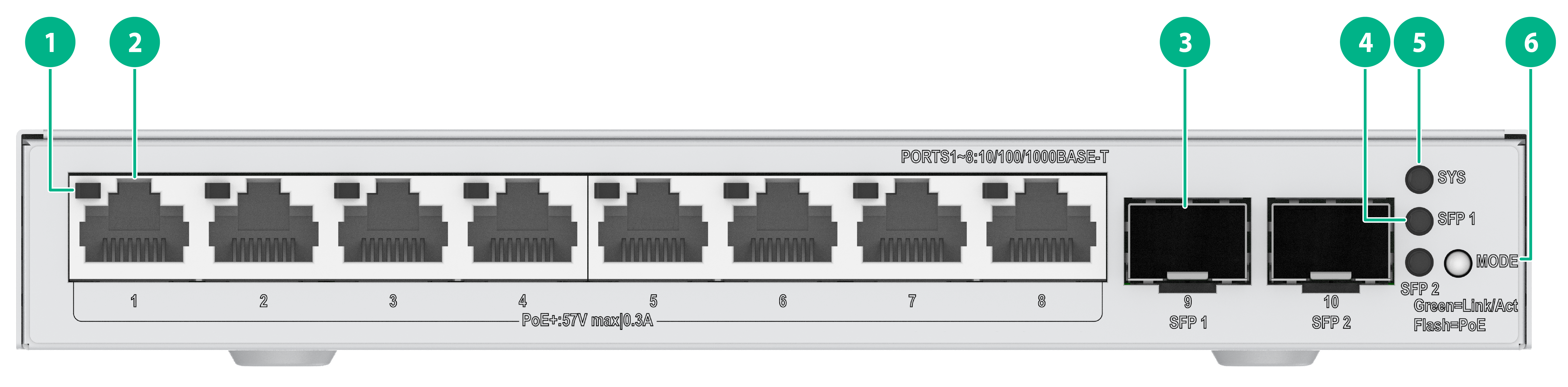
Figure 30 ES4200-8P2ST front panel
|
(1) 10/100/1000BASE-T autosensing Ethernet port LED |
|
|
(2) SFP port |
(3) SFP port LED |
|
(4) System LED (SYS) |
(5) Port mode LED (MODE) |
|
(6) 10/100/1000BASE-T autosensing Ethernet port |
|
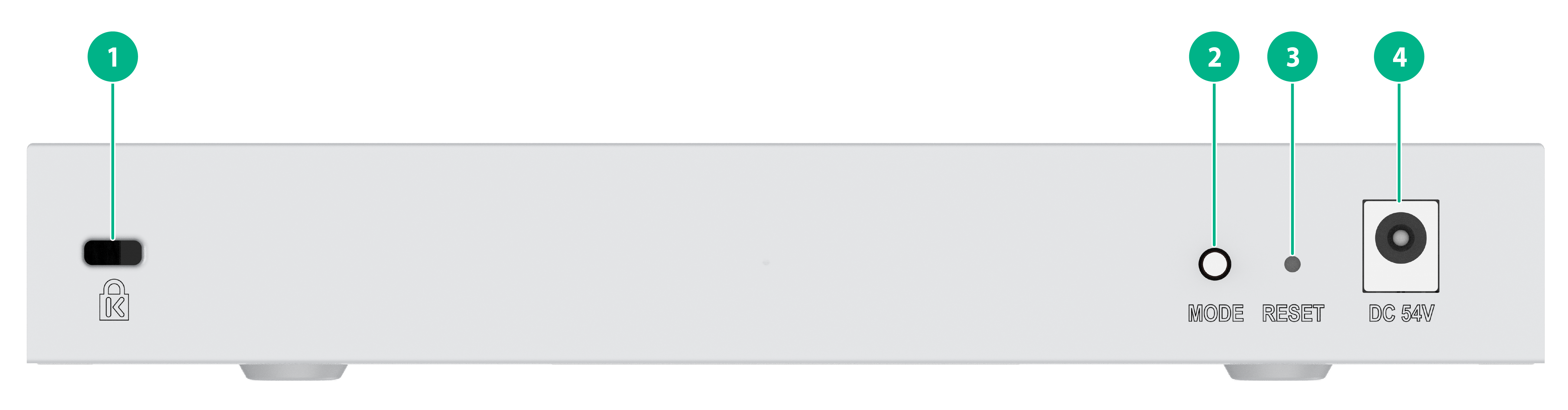
Figure 31 ES4200-8P2ST rear panel
|
(1) Security slot |
(2) Mode switch button for the port mode LED |
|
(3) RESET button |
(4) Adapter input terminal |
|
|
NOTE: The methods for using the RESET button are as follows: · To restart the device, press the button and release the button when the SYS LED turns steady green. · To restore the default Web login password, press and hold the button for 1 to 5 seconds and release the button when the SYS LED flashes red slowly (1 Hz). · To restore the factory default and restart the device, press and hold the button for 5 to 10 seconds and release the button when the SYS LED flashes red rapidly (8 Hz). · If you press and hold the button for over 10 seconds and release the button when the SYS LED turns steady green, no action is performed. |
ES4200-8P2RS
Figure 32 ES4200-8P2RS panel (1)
|
(1) Security slot |
(2) System LED (SYS) |
|
(3) SFP port LED |
|
Figure 33 ES4200-8P2RS panel (2)
|
(1) 10/100/1000BASE-T autosensing Ethernet port LED |
|
|
(2) 10/100/1000BASE-T autosensing Ethernet port |
|
|
(3) PoE power receiving port |
(4) SFP port |
|
(5) Adapter input terminal |
(6) RESET button |
|
(7) Mode switch button for the port mode LED |
(8) Port mode LED (MODE) |
|
|
NOTE: · Each SFP port and the PoE port under it form a combined copper-fiber port. For a combined copper-fiber port to implement data and power transmission, it must be used together with an iOptic 3.0 transceiver module, a hybrid copper-fiber cable, and a combined fiber-copper pigtail. · A common LC transceiver module does not support working in conjunction with a combined copper-fiber port for data and power transmission unless a PoDLC connector is inserted into the module. |
|
|
NOTE: The methods for using the RESET button are as follows: · To restart the device, press the button and release the button when the SYS LED turns steady green. · To restore the default Web login password, press and hold the button for 1 to 5 seconds and release the button when the SYS LED flashes red slowly (1 Hz). · To restore the factory default and restart the device, press and hold the button for 5 to 10 seconds and release the button when the SYS LED flashes red rapidly (8 Hz). · If you press and hold the button for over 10 seconds and release the button when the SYS LED turns steady green, no action is performed. |
ES4200-4P2RMS-B
Figure 34 ES4200-4P2RMS-B panel (1)
|
(1) Port mode LED (MODE) |
(2) Mode switch button for the port mode LED |
|
(3) 10/100/1000BASE-T autosensing Ethernet port LED |
|
|
(4) 10/100/1000BASE-T autosensing Ethernet port |
(5) Adapter input terminal |
|
(6) System LED (SYS) |
(7) SFP port LED |
Figure 35 ES4200-4P2RMS-B panel (2)
|
(1) SFP port |
(2) Type-C USB port |
|
(3) PoE power receiving port |
(4) RESET button |
|
|
NOTE: The Type-C USB port is used for power supply only and does not support data transmission. |
|
|
NOTE: The methods for using the RESET button are as follows: · To restart the device, press the button and release the button when the SYS LED turns steady green. · To restore the default Web login password, press and hold the button for 1 to 5 seconds and release the button when the SYS LED flashes red slowly (1 Hz). · To restore the factory default and restart the device, press and hold the button for 5 to 10 seconds and release the button when the SYS LED flashes red rapidly (8 Hz). · If you press and hold the button for over 10 seconds and release the button when the SYS LED turns steady green, no action is performed. |
ES4200-8T2RX-B
Figure 36 ES4200-8T2RX-B panel (1)
|
(1) 10/100/1000BASE-T autosensing Ethernet port LED |
(2) 10/100/1000BASE-T autosensing Ethernet port |
|
(3) Adapter input terminal |
(4) System LED (SYS) |
|
(5) SFP+ port LED |
|
Figure 37 ES4200-8T2RX-B panel (2)
|
(1) SFP+ port |
(2) Type-C USB port |
|
(3) PoE power receiving port |
(4) RESET button |
|
|
NOTE: The Type-C USB port is used for power supply only and does not support data transmission. |
|
|
NOTE: The methods for using the RESET button are as follows: · To restart the device, press the button and release the button when the SYS LED turns steady green. · To restore the default Web login password, press and hold the button for 1 to 5 seconds and release the button when the SYS LED flashes red slowly (1 Hz). · To restore the factory default and restart the device, press and hold the button for 5 to 10 seconds and release the button when the SYS LED flashes red rapidly (8 Hz). · If you press and hold the button for over 10 seconds and release the button when the SYS LED turns steady green, no action is performed. |
ES4200-8P2RX-B
Figure 38 ES4200-8P2RX-B panel (1)
|
(1) Port mode LED (MODE) |
|
|
(2) 10/100/1000BASE-T autosensing Ethernet port LED |
|
|
(3) Mode switch button for the port mode LED |
(4) 10/100/1000BASE-T autosensing Ethernet port |
|
(5) Adapter input terminal |
(6) System LED (SYS) |
|
(7) SFP port LED |
|
Figure 39 ES4200-8P2RX-B panel (2)
|
(1) SFP+ port |
(2) Type-C USB port |
|
(3) PoE power receiving port |
(4) RESET button |
|
|
NOTE: The Type-C USB port is used for power supply only and does not support data transmission. |
|
|
NOTE: The methods for using the RESET button are as follows: · To restart the device, press the button and release the button when the SYS LED turns steady green. · To restore the default Web login password, press and hold the button for 1 to 5 seconds and release the button when the SYS LED flashes red slowly (1 Hz). · To restore the factory default and restart the device, press and hold the button for 5 to 10 seconds and release the button when the SYS LED flashes red rapidly (8 Hz). · If you press and hold the button for over 10 seconds and release the button when the SYS LED turns steady green, no action is performed. |
ES4200-16P2RS
Figure 40 ES4200-16P2RS front panel
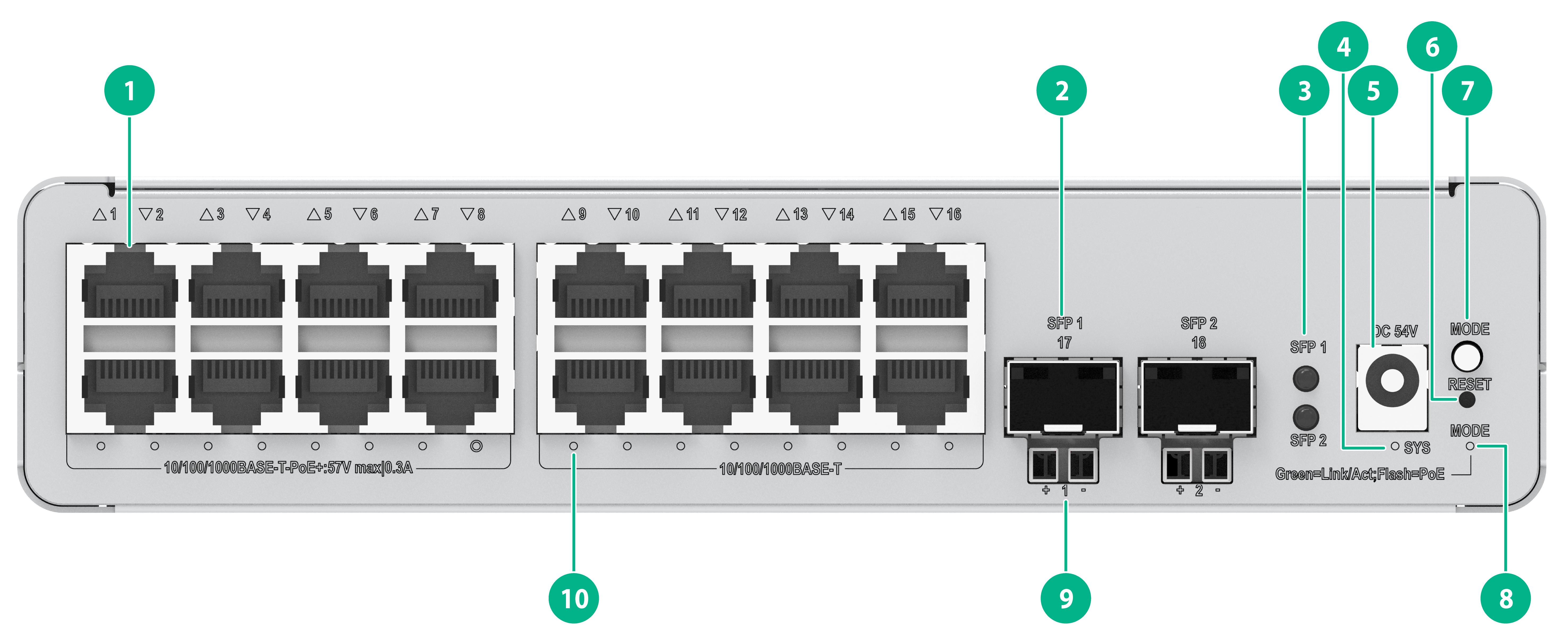
|
(1) 10/100/1000BASE-T autosensing Ethernet port |
(2) SFP port |
|
(3) SFP port LED |
(4) System LED (SYS) |
|
(5) Adapter input terminal |
(6) RESET button |
|
(7) Mode switch button for the port mode LED |
(8) Port mode LED (MODE) |
|
(9) PoE power receiving port |
|
|
(10) 10/100/1000BASE-T autosensing Ethernet port LED |
|
|
|
NOTE: · Each SFP port and the PoE port under it form a combined copper-fiber port. For a combined copper-fiber port to implement data and power transmission, it must be used together with an iOptic 3.0 transceiver module, a hybrid copper-fiber cable, and a combined fiber-copper pigtail. · A common LC transceiver module does not support working in conjunction with a combined copper-fiber port for data and power transmission unless a PoDLC connector is inserted into the module. |
|
|
NOTE: The methods for using the RESET button are as follows: · To restart the device, press the button and release the button when the SYS LED turns steady green. · To restore the default Web login password, press and hold the button for 1 to 5 seconds and release the button when the SYS LED flashes red slowly (1 Hz). · To restore the factory default and restart the device, press and hold the button for 5 to 10 seconds and release the button when the SYS LED flashes red rapidly (8 Hz). · If you press and hold the button for over 10 seconds and release the button when the SYS LED turns steady green, no action is performed. |
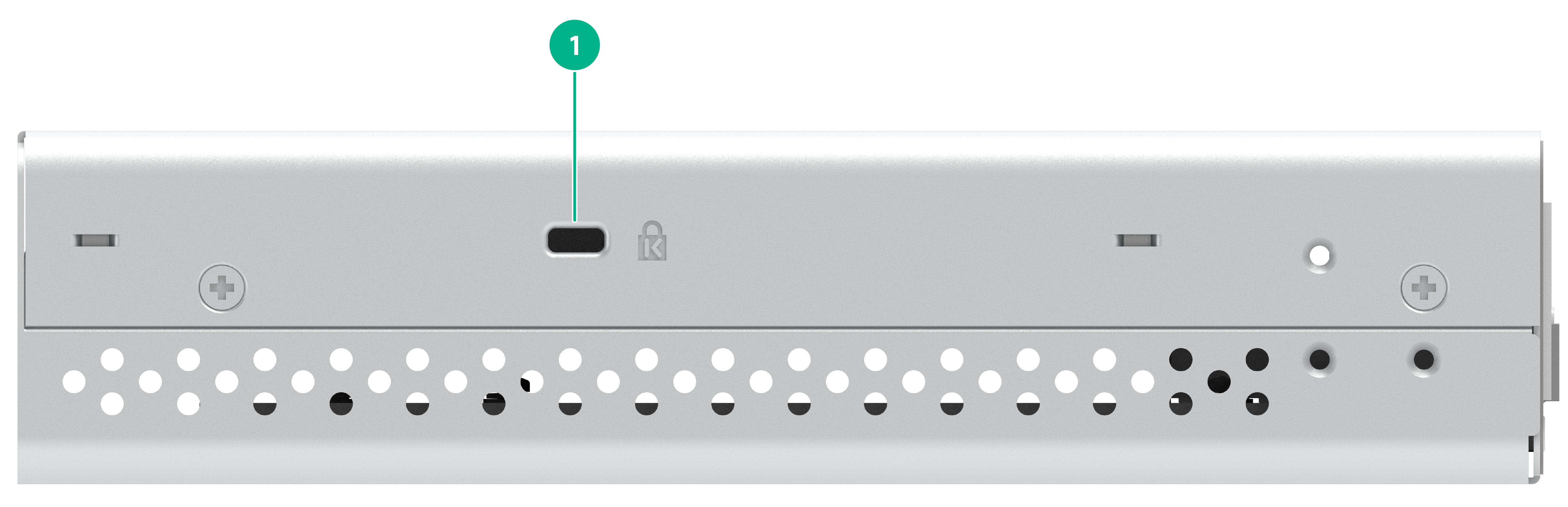
Figure 41 ES4200-16P2RS rear panel
|
(1) Security slot |
ES4200-16P2RX-B
Figure 42 ES4200-16P2RX-B front panel
|
(1) 10/100/1000BASE-T autosensing Ethernet port |
(2) SFP+ port |
|
(3) PoE power receiving port |
(4) Adapter input terminal |
|
(5) Mode switch button for the port mode LED |
(6) RESET button |
|
(7) Port mode LED (MODE) |
(8) System LED (SYS) |
|
(9) SFP+ port LED |
(10) 10/100/1000BASE-T autosensing Ethernet port LED |
|
|
NOTE: The methods for using the RESET button are as follows: · To restart the device, press the button and release the button when the SYS LED turns steady green. · To restore the default Web login password, press and hold the button for 1 to 5 seconds and release the button when the SYS LED flashes red slowly (1 Hz). · To restore the factory default and restart the device, press and hold the button for 5 to 10 seconds and release the button when the SYS LED flashes red rapidly (8 Hz). · If you press and hold the button for over 10 seconds and release the button when the SYS LED turns steady green, no action is performed. |
Figure 43 ES4200-16P2RX-B rear panel
|
(1) Type-C USB port |
|
|
NOTE: The Type-C USB port is used for power supply only and does not support data transmission. |
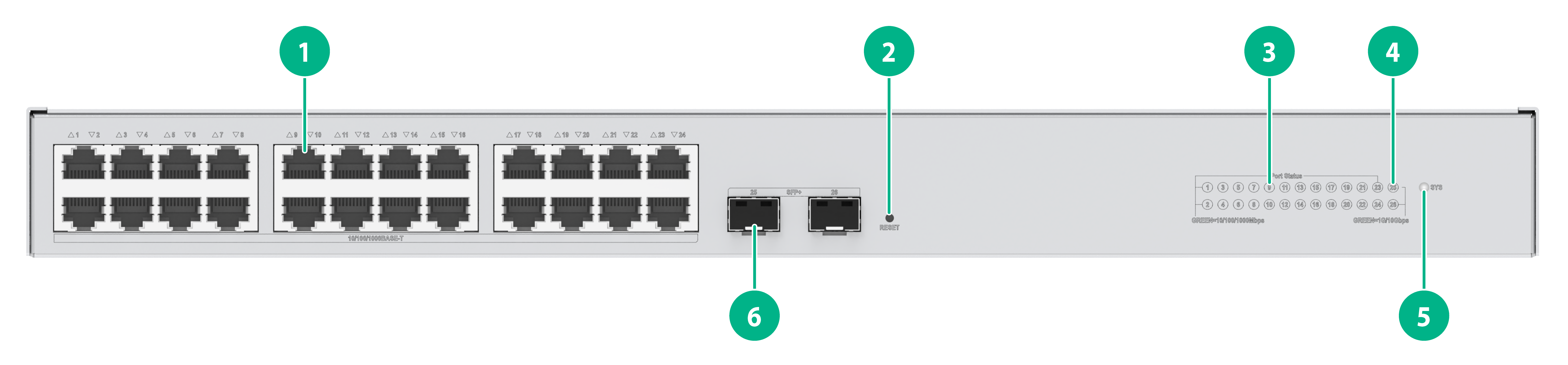
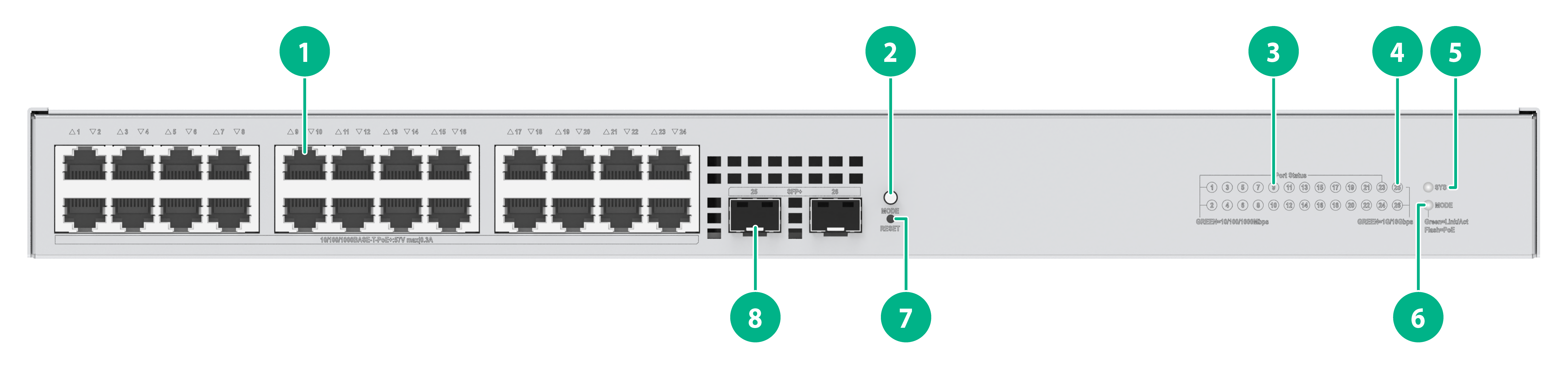
ES4200-24T2X
Figure 44 ES4200-24T2X front panel
|
(1) 10/100/1000BASE-T autosensing Ethernet port |
(2) RESET button |
|
(3) 10/100/1000BASE-T autosensing Ethernet port LED |
(4) SFP+ port LED |
|
(5) System LED (SYS) |
(6) SFP+ port |
|
|
NOTE: The methods for using the RESET button are as follows: · To restart the device, press the button and release the button when the SYS LED turns steady green. · To restore the default Web login password, press and hold the button for 1 to 5 seconds and release the button when the SYS LED flashes red slowly (1 Hz). · To restore the factory default and restart the device, press and hold the button for 5 to 10 seconds and release the button when the SYS LED flashes red rapidly (8 Hz). · If you press and hold the button for over 10 seconds and release the button when the SYS LED turns steady green, no action is performed. |
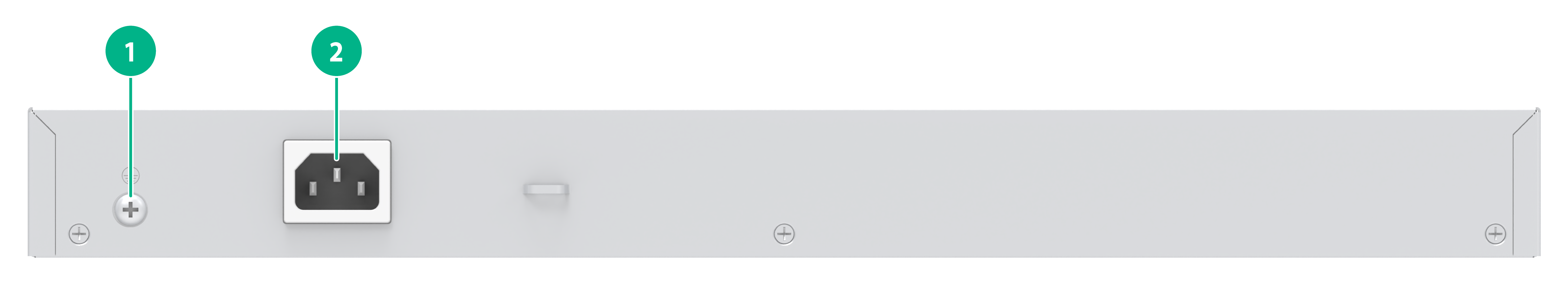
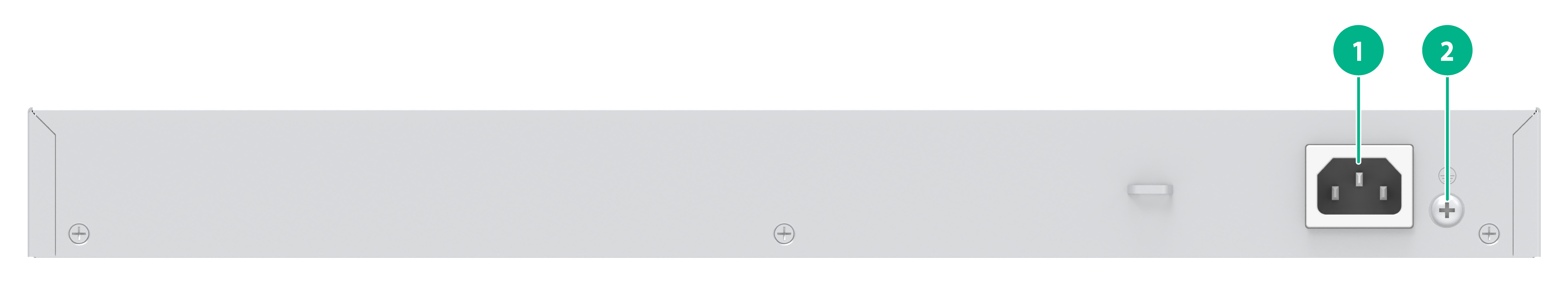
Figure 45 ES4200-24T2X rear panel
|
(1) Grounding screw |
(2) AC power receptacle |
ES4200-24FP2X
Figure 46 ES4200-24FP2X front panel
|
(1) 10/100/1000BASE-T autosensing Ethernet port |
(2) Switch button for the port mode LED |
|
(3) 10/100/1000BASE-T autosensing Ethernet port LED |
(4) SFP+ port LED |
|
(5) System LED (SYS) |
(6) Port mode LED (MODE) |
|
(7) RESET button |
(8) SFP+ port |
|
|
NOTE: The methods for using the RESET button are as follows: · To restart the device, press the button and release the button when the SYS LED turns steady green. · To restore the default Web login password, press and hold the button for 1 to 5 seconds and release the button when the SYS LED flashes red slowly (1 Hz). · To restore the factory default and restart the device, press and hold the button for 5 to 10 seconds and release the button when the SYS LED flashes red rapidly (8 Hz). · If you press and hold the button for over 10 seconds and release the button when the SYS LED turns steady green, no action is performed. |
Figure 47 ES4200-24FP2X rear panel
|
(1) AC power receptacle |
(2) Grounding screw |
Ports
10G/5G/2.5G/1000/100BASE-T Ethernet port
Table 9 10G/5G/2.5G/1000/100BASE-T Ethernet port specifications
|
Item |
Specification |
|
Connector type |
RJ-45 |
|
Transmission rate, duplex mode, and auto MDI/MDI-X |
· 10 Gbps, full duplex · 5 Gbps, full duplex · 2.5 Gbps, full duplex · 1000 Mbps, full duplex · 100 Mbps, half/full duplex · MDI/MDI-X autosensing |
|
Transmission medium and max transmission distance |
· 10G mode: 100 m (328.08 ft) over a category 6 and above shielded twisted pair (STP) cable · 5G mode: 100 m (328.08 ft) over a category 6 and above STP cable · 2.5G mode: 100 m (328.08 ft) over a category 5e and above twisted pair cable · 1G mode: 100 m (328.08 ft) over a category 5e and above twisted pair cable · 100M mode: 140 m (459.32 ft) over a category 5e and above twisted pair cable |
|
Transmission medium |
Category 5e and above twisted pair cable |
|
Compliant standard |
IEEE 802.3ab, 802.3an, 802.3bz |
|
Compatible switch models |
ES4200-8MG |
2.5G/1000/100BASE-T Ethernet port
Table 10 2.5G/1000/100BASE-T Ethernet port specifications
|
Item |
Specification |
|
Connector type |
RJ-45 |
|
Transmission rate, duplex mode, and auto MDI/MDI-X |
· 10 Gbps, full duplex · 5 Gbps, full duplex · 2.5 Gbps, full duplex · 1000 Mbps, full duplex · 100 Mbps, half/full duplex · MDI/MDI-X autosensing |
|
Max transmission distance |
100 m (328.08 ft) |
|
Transmission medium |
Category 5 and above twisted pair cable |
|
Compliant standard |
IEEE 802.3ab, 802.3an, 802.3bz |
|
Compatible switch models |
ES4200-4UMG2X |
10/100/1000BASE-T Ethernet port
Table 11 10/100/1000BASE-T Ethernet port specifications
|
Item |
Specification |
|
Connector |
RJ-45 |
|
Transmission rate, duplex mode, and auto MDI/MDI-X |
· 10 Mbps, half/full duplex · 100 Mbps, half/full duplex · 1000 Mbps, full duplex · MDI/MDI-X autosensing |
|
Max transmission distance |
100 m (328.08 ft) |
|
Transmission medium |
Category 5 and above twisted pair cable |
|
Compliant standard |
IEEE 802.3i, 802.3u, 802.3ab |
|
Compatible switch models |
All models (except ES4200-24T2X and ES4200-24FP2X) |
SFP ports
Table 12 SFP port specifications (1)
|
Item |
Specification |
|
Port type |
SFP ports |
|
Port attributes |
Supports the Gigabit SFP transceiver modules and cables listed in Table 15. |
|
Compatible switch models |
· ES4200-8T2ST · ES4200-8T2RS · ES4200-8T2S · ES4200-8P2S · ES4200-8P2ST · ES4200-8P2RS · ES4200-16P2RS |
Table 13 SFP port specifications (2)
|
Item |
Specification |
|
Port type |
SFP ports |
|
Port attributes |
Supports the Gigabit SFP transceiver modules and cables listed in Table 15. Supports the 2.5G SFP transceiver modules listed in Table 19. |
|
Compatible switch models |
· ES4200-2T1S-M · ES4200-4T1MS-B · ES4200-4T2RMS-B · ES4200-4T2ST · ES4200-4P2ST · ES4200-4P2RMS-B |
|
Restrictions and guidelines |
In versions earlier than R8811, some SFP ports support speed switching between 1 Gbps and 2.5 Gbps. For the change to take effect, switch the port speed on the Web interface and restart the device. In R8811 and later versions, SFP ports are speed-autosensing. After you change the transceiver module to a 1G or 2.5G one for a port, the device automatically restarts for speed autosensing. The SFP ports include: · SFP port on switch models with only one SFP port. · SFP port SFP2 on switch models with two SFP ports. |
Table 14 SFP port specifications (3)
|
Item |
Specification |
|
Port type |
SFP ports |
|
Port attributes |
Supports the Gigabit SFP transceiver modules and cables listed in Table 15. Supports the 2.5G SFP transceiver modules listed in Table 21. |
|
Compatible switch models |
· ES4200-4P2RS · ES4200-4P2RST |
|
Restrictions and guidelines |
In versions earlier than R8811, SFP ports support speed switching between 1 Gbps and 2.5 Gbps. For the change to take effect, switch the port speed on the Web interface and restart the device. In R8811 and later versions, SFP ports are speed-autosensing. After you change the transceiver module to a 1G or 2.5G one for a port, the device automatically restarts for speed autosensing. |
Table 15 GE SFP transceiver modules and cables (1)
|
Transceiver module/cable type |
Transceiver module/cable name |
Central wavelength |
Connector |
Cable specifications |
Mode bandwidth (MHz*km) |
Max transmission distance |
|
SFP module |
SFP-GE-SX-MM850-A |
850 nm |
LC |
50/125 µm, MMF |
500 |
550 m (1804.46 ft) |
|
400 |
500 m (1640.42 ft) |
|||||
|
62.5/125 µm, MMF |
200 |
275 m (902.23 ft) |
||||
|
160 |
200 m (656.17 ft) |
|||||
|
SFP-GE-LX-SM1310-A |
1310 nm |
LC |
9/125 µm, SMF |
N/A |
10 km (6.21 miles) |
|
|
50/125 µm, MMF |
500/400 |
550 m (1804.46 ft) |
||||
|
62.5/125 µm, MMF |
500 |
550 m (1804.46 ft) |
||||
|
SFP-GE-LX-SM1310-BIDI |
TX: 1310 nm RX: 1490 nm |
LC |
9/125 µm, SMF |
N/A |
10 km (6.21 miles) |
|
|
SFP-GE-LX-SM1490-BIDI |
TX: 1490 nm RX: 1310 nm |
LC |
9/125 µm, SMF |
N/A |
10 km (6.21 miles) |
|
|
SFP-GE-LX-SM1310-BIDI-I |
TX: 1310 nm RX: 1490 nm |
LC |
9/125 µm, SMF |
N/A |
10 km (6.21 miles) |
|
|
SFP-GE-LX-SM1490-BIDI-I |
TX: 1490 nm RX: 1310 nm |
LC |
9/125 µm, SMF |
N/A |
10 km (6.21 miles) |
|
|
SFP cable |
SFP-STACK-Kit |
N/A |
N/A |
SFP cable |
N/A |
1.5 m (4.92 ft) |
|
|
IMPORTANT: The SFP-GE-LX-SM1310-BIDI and SFP-GE-LX-SM1490-BIDI transceiver modules, and SFP-GE-LX-SM1310-BIDI-I and SFP-GE-LX-SM1490-BIDI-I transceiver modules must be used in pairs. For example, if one end uses the SFP-GE-LX-SM1310-BIDI transceiver module, the other end must use the SFP-GE-LX-SM1490-BIDI transceiver module. |
Table 16 GE SFP transceiver modules and cables (2)
|
Transceiver module/cable type |
Transceiver module/cable model |
Central wavelength |
Connector |
Cable specifications |
Mode bandwidth (MHz*km) |
Maximum transmission distance |
|
SFP copper transceiver module |
SFP-GE-T |
N/A |
RJ-45 |
Twisted pair cable |
N/A |
100 m (328.08 ft) |
|
SFP-GE-T-D |
N/A |
RJ-45 |
Twisted pair cable |
N/A |
100 m (328.08 ft) |
|
|
SFP module |
SFP-GE-LH40-SM1310 |
1310 nm |
LC |
9/125 µm, SMF |
N/A |
40 km (24.86 miles) |
|
SFP-GE-LH40-SM1310-D |
1310 nm |
LC |
9/125 µm, SMF |
N/A |
40 km (24.86 miles) |
|
|
SFP-GE-LH40-SM1550 |
1550 nm |
LC |
9/125 µm, SMF |
N/A |
40 km (24.86 miles) |
|
|
SFP-GE-LH80-SM1550 |
1550 nm |
LC |
9/125 µm, SMF |
N/A |
80 km (49.71 miles) |
|
|
SFP-GE-SX-MM850-A |
850 nm |
LC |
50/125 µm, MMF |
500 |
550 m (1804.46 ft) |
|
|
400 |
500 m (1804.46 ft) |
|||||
|
62.5/125 µm, MMF |
200 |
275 m (902.23 ft) |
||||
|
160 |
200 m (656.17 ft) |
|||||
|
SFP-GE-LX-SM1310-A |
1310 nm |
LC |
9/125 µm, SMF |
N/A |
10 km (6.21 miles) |
|
|
50/125 µm, MMF |
500/400 |
550 m (1804.46 ft) |
||||
|
62.5/125 µm, MMF |
500 |
550 m (1804.46 ft) |
||||
|
SFP-GE-LX-SM1310-BIDI |
TX: 1310 nm RX: 1490 nm |
LC |
9/125 µm, SMF |
N/A |
10 km (6.21 miles) |
|
|
SFP-GE-LX-SM1490-BIDI |
TX: 1490 nm RX: 1310 nm |
N/A |
||||
|
SFP-GE-LX-SM1310-BIDI-I |
TX: 1310 nm RX: 1490 nm |
LC |
9/125 µm, SMF |
N/A |
10 km (6.21 miles) |
|
|
SFP-GE-LX-SM1490-BIDI-I |
TX: 1490 nm RX: 1310 nm |
N/A |
|
|
IMPORTANT: The SFP-GE-LX-SM1310-BIDI and SFP-GE-LX-SM1490-BIDI transceiver modules, and SFP-GE-LX-SM1310-BIDI-I and SFP-GE-LX-SM1490-BIDI-I transceiver modules must be used in pairs. For example, if one end uses the SFP-GE-LX-SM1310-BIDI transceiver module, the other end must use the SFP-GE-LX-SM1490-BIDI transceiver module. |
Table 17 GE SFP transceiver modules and cables (3)
|
Transceiver module/cable type |
Transceiver module/cable name |
Central wavelength |
Connector |
Cable specifications |
Mode bandwidth (MHz*km) |
Maximum transmission distance |
|
SFP copper transceiver module |
SFP-GE-T |
N/A |
RJ-45 |
Twisted pair cable |
N/A |
100 m (328.08 ft) |
|
SFP-GE-T-D |
N/A |
RJ-45 |
Twisted pair cable |
N/A |
100 m (328.08 ft) |
|
|
iOptic 3.0 dedicated transceiver module |
SFP-GE-LX-SM1310-F |
1310 nm |
PoDLC |
Hybrid copper-fiber cable |
N/A |
10 km (6.21 miles) |
|
SFP module |
SFP-GE-SX-MM850-A |
850 nm |
LC |
50/125 µm, MMF |
500 |
550 m (1804.46 ft) |
|
400 |
500 m (1640.42 ft) |
|||||
|
62.5/125 µm, MMF |
200 |
275 m (902.23 ft) |
||||
|
160 |
200 m (656.17 ft) |
|||||
|
SFP-GE-LX-SM1310-A |
1310 nm |
LC |
9/125 µm, SMF |
N/A |
10 km (6.21 miles) |
|
|
50/125 µm, MMF |
500/400 |
550 m (1804.46 ft) |
||||
|
62.5/125 µm, MMF |
500 |
550 m (1804.46 ft) |
||||
|
SFP-GE-LX-SM1310-BIDI |
TX: 1310 nm RX: 1490 nm |
LC |
9/125 µm, SMF |
N/A |
10 km (6.21 miles) |
|
|
SFP-GE-LX-SM1490-BIDI |
TX: 1490 nm RX: 1310 nm |
LC |
9/125 µm, SMF |
N/A |
10 km (6.21 miles) |
|
|
SFP-GE-LX-SM1310-BIDI-I |
TX: 1310 nm RX: 1490 nm |
LC |
9/125 µm, SMF |
N/A |
10 km (6.21 miles) |
|
|
SFP-GE-LX-SM1490-BIDI-I |
TX: 1490 nm RX: 1310 nm |
LC |
9/125 µm, SMF |
N/A |
10 km (6.21 miles) |
|
|
SFP cable |
SFP-STACK-Kit |
N/A |
N/A |
SFP cable |
N/A |
1.5 m (4.92 ft) |
|
|
IMPORTANT: The SFP-GE-LX-SM1310-BIDI and SFP-GE-LX-SM1490-BIDI transceiver modules, and SFP-GE-LX-SM1310-BIDI-I and SFP-GE-LX-SM1490-BIDI-I transceiver modules must be used in pairs. For example, if one end uses the SFP-GE-LX-SM1310-BIDI transceiver module, the other end must use the SFP-GE-LX-SM1490-BIDI transceiver module. |
Table 18 GE SFP transceiver modules and cables (4)
|
Transceiver module/cable type |
Transceiver module/cable name |
Central wavelength |
Connector |
Cable specifications |
Mode bandwidth (MHz*km) |
Maximum transmission distance |
|
SFP copper transceiver module |
SFP-GE-T |
N/A |
RJ-45 |
Twisted pair cable |
N/A |
100 m (328.08 ft) |
|
SFP-GE-T-D |
N/A |
RJ-45 |
Twisted pair cable |
N/A |
100 m (328.08 ft) |
|
|
SFP module |
SFP-GE-SX-MM850-A |
850 nm |
LC |
50/125 µm, MMF |
500 |
550 m (1804.46 ft) |
|
400 |
500 m (1640.42 ft) |
|||||
|
62.5/125 µm, MMF |
200 |
275 m (902.23 ft) |
||||
|
160 |
200 m (656.17 ft) |
|||||
|
SFP-GE-SX-MM850-D |
850 nm |
LC |
50/125 µm, MMF |
500 |
550 m (1804.46 ft) |
|
|
400 |
500 m (1640.42 ft) |
|||||
|
62.5/125 µm, MMF |
200 |
275 m (902.23 ft) |
||||
|
160 |
220 m (721.78 ft) |
|||||
|
SFP-GE-SX-MM850-S |
850 nm |
LC |
50/125 µm, MMF |
500 |
550 m (1804.46 ft) |
|
|
400 |
500 m (1640.42 ft) |
|||||
|
62.5/125 µm, MMF |
200 |
275 m (902.23 ft) |
||||
|
160 |
220 m (721.78 ft) |
|||||
|
SFP-GE-LX-SM1310-A |
1310 nm |
LC |
9/125 µm, SMF |
N/A |
10 km (6.21 miles) |
|
|
50/125 µm, MMF |
500/400 |
550 m (1804.46 ft) |
||||
|
62.5/125 µm, MMF |
500 |
550 m (1804.46 ft) |
||||
|
SFP-GE-LX-SM1310-D |
1310 nm |
LC |
9/125 µm, SMF |
N/A |
10 km (6.21 miles) |
|
|
50/125 µm, MMF |
500/400 |
550 m (1804.46 ft) |
||||
|
62.5/125 µm, MMF |
500 |
550 m (1804.46 ft) |
||||
|
SFP-GE-LX-SM1310-S |
1310 nm |
LC |
9/125 µm, SMF |
N/A |
10 km (6.21 miles) |
|
|
50/125 µm, MMF |
500/400 |
550 m (1804.46 ft) |
||||
|
62.5/125 µm, MMF |
500 |
550 m (1804.46 ft) |
||||
|
SFP-GE-LH40-SM1310 |
1310 nm |
LC |
9/125 µm, SMF |
N/A |
40 km (24.86 miles) |
|
|
SFP-GE-LH40-SM1310-D |
1310 nm |
LC |
9/125 µm, SMF |
N/A |
40 km (24.86 miles) |
|
|
SFP-GE-LH40-SM1310-S |
1310 nm |
LC |
9/125 µm, SMF |
N/A |
40 km (24.86 miles) |
|
|
SFP-GE-LH40-SM1550 |
1550 nm |
LC |
9/125 µm, SMF |
N/A |
40 km (24.86 miles) |
|
|
SFP-GE-LH100-SM1550 |
1550 nm |
LC |
9/125 µm, SMF |
N/A |
100 km (62.14 miles) |
|
|
SFP-GE-LH40-SM1310-I |
1310 nm |
LC |
9/125 µm, SMF |
N/A |
40 km (24.86 miles) |
|
|
SFP-GE-LH20-SM1310-I |
1310 nm |
LC |
9/125 µm, SMF |
N/A |
20 km (12.43 miles) |
|
|
SFP-GE-LX10-SM1310 |
1310 nm |
LC |
9/125 µm, SMF |
N/A |
10 km (6.21 miles) |
|
|
SFP-GE-LX-SM1310-F |
1310 nm |
PoDLC |
9/125 µm, SMF |
N/A |
10 km (6.21 miles) |
|
|
SFP-GE-LH80-SM1550 |
1550 nm |
LC |
9/125 µm, SMF |
N/A |
80 km (49.71 miles) |
|
|
SFP-GE-LH80-SM1550-D |
1550 nm |
LC |
9/125 µm, SMF |
N/A |
80 km (49.71 miles) |
|
|
SFP-GE-LX-SM1310-BIDI |
TX: 1310 nm RX: 1490 nm |
LC |
9/125 µm, SMF |
N/A |
10 km (6.21 miles) |
|
|
SFP-GE-LX-SM1490-BIDI |
TX: 1490 nm RX: 1310 nm |
LC |
9/125 µm, SMF |
N/A |
10 km (6.21 miles) |
|
|
SFP-GE-LX-SM1310-BIDI-S |
TX: 1310 nm RX: 1490 nm |
LC |
9/125 µm, SMF |
N/A |
10 km (6.21 miles) |
|
|
SFP-GE-LX-SM1490-BIDI-S |
TX: 1490 nm RX: 1310 nm |
LC |
9/125 µm, SMF |
N/A |
10 km (6.21 miles) |
|
|
SFP-GE-LX-SM1310-BIDI-I |
TX: 1310 nm RX: 1490 nm |
LC |
9/125 µm, SMF |
N/A |
10 km (6.21 miles) |
|
|
SFP-GE-LX-SM1490-BIDI-I |
TX: 1490 nm RX: 1310 nm |
LC |
9/125 µm, SMF |
N/A |
10 km (6.21 miles) |
|
|
SFP-GE-LH40-SM1310-BIDI |
TX: 1310nm RX: 1550 nm |
LC |
9/125 µm, SMF |
N/A |
40 km (24.86 miles) |
|
|
SFP-GE-LH40-SM1550-BIDI |
TX: 1550 nm RX: 1310 nm |
LC |
9/125 µm, SMF |
N/A |
40 km (24.86 miles) |
|
|
SFP-GE-LH70-SM1490-BIDI |
TX: 1490 nm RX: 1550 nm |
LC |
9/125 µm, SMF |
N/A |
70 km (43.50 miles) |
|
|
SFP-GE-LH70-SM1550-BIDI |
TX: 1550 nm RX: 1490 nm |
LC |
9/125 µm, SMF |
N/A |
70 km (43.50 miles) |
|
|
SFP cable |
SFP-STACK-Kit |
N/A |
N/A |
SFP cable |
N/A |
1.5 m (4.92 ft) |
|
SFP-STACK-Kit-S |
N/A |
N/A |
SFP cable |
N/A |
1.5 m (4.92 ft) |
|
|
IMPORTANT: Use the following transceiver modules in pairs: · SFP-GE-LX-SM1310-BIDI and SFP-GE-LX-SM1490-BIDI transceiver modules. · SFP-GE-LX-SM1310-BIDI-S and SFP-GE-LX-SM1490-BIDI-S transceiver modules. · SFP-GE-LX-SM1310-BIDI-I and SFP-GE-LX-SM1490-BIDI-I transceiver modules. · SFP-GE-LH40-SM1310-BIDI and SFP-GE-LH40-SM1550-BIDI transceiver modules. · SFP-GE-LH70-SM1490-BIDI and SFP-GE-LH70-SM1550-BIDI transceiver modules. For example, if one end uses the SFP-GE-LX-SM1310-BIDI transceiver module, the other end must use the SFP-GE-LX-SM1490-BIDI transceiver module. |
|
|
NOTE: The iOptic 3.0 dedicated transceiver module must be used in conjunction with a combined fiber-copper pigtail or hybrid copper-fiber cable for data transmission and power supply/reception. |
Table 19 2.5G SFP transceiver modules (1)
|
Transceiver module/cable type |
Transceiver module/cable name |
Central wavelength |
Connector |
Fiber specifications |
Mode bandwidth (MHz*km) |
Maximum transmission distance |
|
2.5G SFP transceiver module |
SFP-2.5G-LX10-SM1310-DR-I |
1310 nm |
LC |
9/125 µm, SMF |
N/A |
10 km (6.21 miles) |
Table 20 2.5G SFP transceiver modules (2)
|
Transceiver module/cable type |
Transceiver module/cable name |
Central wavelength |
Connector |
Fiber specifications |
Mode bandwidth (MHz*km) |
Maximum transmission distance |
|
2.5G SFP transceiver module |
SFP-2.5G-LX-SM1310 |
1310 nm |
LC |
9/125 µm, SMF |
N/A |
2 km (1.24 miles) |
Table 21 2.5G SFP transceiver modules (3)
|
Transceiver module/cable type |
Transceiver module/cable name |
Central wavelength |
Connector |
Cable specifications |
Mode bandwidth (MHz*km) |
Maximum transmission distance |
|
2.5G SFP iOptic 3.0 dedicated transceiver module |
SFP-2.5G-LX10-SM1310-DR-I-F |
1310 nm |
PoDLC |
Hybrid copper-fiber cable |
N/A |
10 km (6.21 miles) |
|
|
NOTE: · As a best practice, use H3C transceiver modules and cables on this series of switches. · The H3C transceiver modules and cables are subject to change over time. For the most recent list of H3C transceiver modules and cables, contact your H3C Support or marketing staff. · For the specifications of H3C transceiver modules and cables, see H3C Transceiver Modules User Guide. |
SFP+ ports
Table 22 SFP+ port specifications (1)
|
Item |
Specification |
|
Port type |
SFP+ ports |
|
Port attributes |
Supports the 10-Gigabit SFP+ transceiver modules and cables listed in Table 26. Supports the Gigabit SFP transceiver modules and cables listed in Table 15. Supports the 2.5G SFP transceiver modules listed in Table 19. |
|
Compatible switch models |
· ES4200-8P2RX-B · ES4200-16P2RX-B |
|
Restrictions and guidelines |
The ES4200-8P2RX-B does not support selecting cables or fibers. |
Table 23 SFP+ port specifications (2)
|
Item |
Specification |
|
Port type |
SFP+ ports |
|
Port attributes |
Supports the 10-Gigabit SFP+ transceiver modules and cables listed in Table 27. Supports the Gigabit SFP transceiver modules and cables listed in Table 17. Supports the 2.5G SFP transceiver modules listed in Table 21. |
|
Compatible switch models |
ES4200-16T2RX |
Table 24 SFP+ port specifications (3)
|
Item |
Specification |
|
Port type |
SFP+ ports |
|
Port attributes |
Supports the 10-Gigabit SFP+ transceiver modules and cables listed in Table 28. Supports the Gigabit SFP transceiver modules and cables listed in Table 18. Supports the 2.5G SFP transceiver modules listed in Table 19, Table 20, and Table 21. |
|
Compatible switch models |
ES4200-4UMG2X ES4200-24T2X ES4200-24FP2X |
|
Restrictions and guidelines |
When transceiver modules with transmission distance equal to or greater than 80 km (49.71 miles) are installed on the ES4200-24T2X switch, the operating temperature cannot higher than 40°C (104°F). |
Table 25 SFP+ port specifications (4)
|
Item |
Specification |
|
Port type |
SFP+ ports |
|
Port attributes |
Supports the 10-Gigabit SFP+ transceiver modules and cables listed in Table 28. Supports the Gigabit SFP transceiver modules and cables listed in Table 16. Supports the 2.5G SFP transceiver modules listed in Table 21. |
|
Compatible switch models |
ES4200-8T2RX-B |
Table 26 10-Gigabit SFP+ transceiver modules/cables supported by the SFP+ port (1)
|
Transceiver module/cable type |
Transceiver module/cable name |
Central wavelength |
Connector |
Fiber specifications |
Mode bandwidth (MHz*km) |
Maximum transmission distance |
|
SFP+ copper cable |
LSWM1STK |
N/A |
N/A |
SFP+ copper cable |
N/A |
0.65 m (2.13 ft) |
|
LSWM2STK |
1.2 m (3.94 ft) |
|||||
|
LSWM3STK |
3 m (9.84 ft) |
|||||
|
LSTM1STK |
5 m (16.40 ft) |
|||||
|
SFP+ fiber cable |
SFP-XG-D-AOC-7M |
N/A |
N/A |
SFP+ fiber cable |
N/A |
7 m (22.97 ft) |
|
SFP-XG-D-AOC-10M |
10 m (32.81 ft) |
|||||
|
SFP-XG-D-AOC-20M |
20 m (65.62 ft) |
Table 27 10-Gigabit SFP+ transceiver modules/cables supported by the SFP+ port (2)
|
Transceiver module/cable type |
Transceiver module/cable name |
Central wavelength |
Connector |
Cable specifications |
Mode bandwidth (MHz*km) |
Maximum transmission distance |
|
SFP+ transceiver module |
SFP-XG-LX-SM1310-D |
1310 nm |
LC |
9/125 µm, SMF |
N/A |
10 km (6.21 miles) |
|
SFP-XG-SX-MM850-D |
850 nm |
LC |
50/125 µm, MMF |
4700 |
400 m (1312.34 ft) |
|
|
2000 |
300 m (984.25 ft) |
|||||
|
400 |
66 m (216.54 ft) |
|||||
|
62.5/125 µm, MMF |
200 |
33 m (108.27 ft) |
||||
|
160 |
26 m (85.30 ft) |
|||||
|
SFP+ copper cable |
LSWM1STK |
N/A |
N/A |
SFP+ copper cable |
N/A |
0.65 m (2.13 ft) |
|
LSWM2STK |
1.2 m (3.94 ft) |
|||||
|
LSWM3STK |
3 m (9.84 ft) |
|||||
|
LSTM1STK |
5 m (16.40 ft) |
|||||
|
SFP+ fiber cable |
SFP-XG-D-AOC-7M |
N/A |
N/A |
SFP+ fiber cable |
N/A |
7 m (22.97 ft) |
|
SFP-XG-D-AOC-10M |
10 m (32.81 ft) |
|||||
|
SFP-XG-D-AOC-20M |
20 m (65.62 ft) |
Table 28 10-Gigabit SFP+ transceiver modules/cables supported by the SFP+ port (3)
|
Transceiver module/cable type |
Transceiver module/cable name |
Central wavelength |
Connector |
Cable specifications |
Mode bandwidth (MHz*km) |
Maximum transmission distance |
|
SFP+ copper transceiver module |
SFP-10GE-T |
N/A |
RJ-45 |
Category 6e STP or category 7 twisted pair cable |
N/A |
30 m (98.43 ft) |
|
Category 5e twisted pair cable |
N/A |
100 m (328.08 ft) |
||||
|
SFP+ optical transceiver module |
SFP-XG-LH40-SM1550 |
1550 nm |
LC |
9/125 µm, SMF |
N/A |
40 km (24.86 miles) |
|
SFP-XG-LH40-SM1550-D |
1550 nm |
LC |
9/125 µm, SMF |
N/A |
40 km (24.86 miles) |
|
|
SFP-XG-LH40-SM1550-S |
1550 nm |
LC |
9/125 µm, SMF |
N/A |
40 km (24.86 miles) |
|
|
SFP-XG-LH80-SM1550 |
1550 nm |
LC |
9/125 µm, SMF |
N/A |
80 km (49.71 miles) |
|
|
SFP-XG-LH80-SM1550-D |
1550 nm |
LC |
9/125 µm, SMF |
N/A |
80 km (49.71 miles) |
|
|
SFP-XG-LX-SM1310-D |
1310 nm |
LC |
9/125 µm, SMF |
N/A |
10 km (6.21 miles) |
|
|
SFP-XG-LX-SM1310-E |
1310 nm |
LC |
9/125 µm, SMF |
N/A |
10 km (6.21 miles) |
|
|
SFP-XG-LX-SM1310-S |
1310 nm |
LC |
9/125 µm, SMF |
N/A |
10 km (6.21 miles) |
|
|
SFP-XG-LX-SM1310 |
1310 nm |
LC |
9/125 µm, SMF |
N/A |
10 km (6.21 miles) |
|
|
SFP-XG-SX-MM850-D |
850 nm |
LC |
50/125 µm, MMF |
4700 |
400 m (1312.34 ft) |
|
|
2000 |
300 m (984.25 ft) |
|||||
|
500 |
82 m (269.03 ft) |
|||||
|
400 |
66 m (216.54 ft) |
|||||
|
62.5/125 µm, MMF |
200 |
33 m (108.27 ft) |
||||
|
160 |
26 m (85.30 ft) |
|||||
|
SFP-XG-SX-MM850-E |
850 nm |
LC |
50/125 µm, MMF |
4700 |
400 m (1312.34 ft) |
|
|
2000 |
300 m (984.25 ft) |
|||||
|
500 |
82 m (269.03 ft) |
|||||
|
400 |
66 m (216.54 ft) |
|||||
|
62.5/125 µm, MMF |
200 |
33 m (108.27 ft) |
||||
|
160 |
26 m (85.30 ft) |
|||||
|
SFP-XG-SX-MM850-S |
850 nm |
LC |
50/125 µm, MMF |
4700 |
400 m (1312.34 ft) |
|
|
2000 |
300 m (984.25 ft) |
|||||
|
500 |
82 m (269.03 ft) |
|||||
|
400 |
66 m (216.54 ft) |
|||||
|
62.5/125 µm, MMF |
200 |
33 m (108.27 ft) |
||||
|
160 |
26 m (85.30 ft) |
|||||
|
SFP-XG-SX-MM850-A |
850 nm |
LC |
50/125 µm, MMF |
4700 |
400 m (1312.34 ft) |
|
|
2000 |
300 m (984.25 ft) |
|||||
|
500 |
82 m (269.03 ft) |
|||||
|
400 |
66 m (216.54 ft) |
|||||
|
62.5/125 µm, MMF |
200 |
33 m (108.27 ft) |
||||
|
160 |
26 m (85.30 ft) |
|||||
|
SFP-XG-SX-MM850-H |
850 nm |
LC |
50/125 µm, MMF |
4700 |
400 m (1312.34 ft) |
|
|
2000 |
300 m (984.25 ft) |
|||||
|
500 |
82 m (269.03 ft) |
|||||
|
400 |
66 m (216.54 ft) |
|||||
|
62.5/125 µm, MMF |
200 |
33 m (108.27 ft) |
||||
|
160 |
26 m (85.30 ft) |
|||||
|
SFP-XG-CPRI-IR-SM1310 |
1310 nm |
LC |
9/125 µm, SMF |
N/A |
1.4 km (0.87 miles) |
|
|
SFP-XG-CPRI-LR-SM1310 |
1310 nm |
LC |
9/125 µm, SMF |
N/A |
10 km (6.21 miles) |
|
|
SFP-XG-LX-SM1270-BIDI |
TX: 1270 RX: 1330 |
LC |
9/125 µm, SMF |
N/A |
10 km (6.21 miles) |
|
|
SFP-XG-LX-SM1270-BIDI-S |
TX: 1270 RX: 1330 |
LC |
9/125 µm, SMF |
N/A |
10 km (6.21 miles) |
|
|
SFP-XG-LX-SM1330-BIDI |
TX: 1330 RX: 1270 |
LC |
9/125 µm, SMF |
N/A |
10 km (6.21 miles) |
|
|
SFP-XG-LX-SM1330-BIDI-S |
TX: 1330 RX: 1270 |
LC |
9/125 µm, SMF |
N/A |
10 km (6.21 miles) |
|
|
SFP-XG-LH40-SM1270-BIDI |
TX: 1270 RX: 1330 |
LC |
9/125 µm, SMF |
N/A |
40 km (24.86 miles) |
|
|
SFP-XG-LH40-SM1330-BIDI |
TX: 1330 RX: 1270 |
LC |
9/125 µm, SMF |
N/A |
40 km (24.86 miles) |
|
|
SFP-XG-LH40-SM1330-BIDI |
TX: 1330 RX: 1270 |
LC |
9/125 µm, SMF |
N/A |
40 km (24.86 miles) |
|
|
SFP-XG-LH80-SM1490-BIDI |
TX: 1490 RX: 1550 |
LC |
9/125 µm, SMF |
N/A |
80 km (49.71 miles) |
|
|
SFP-XG-LH80-SM1550-BIDI |
TX: 1550 RX: 1490 |
LC |
9/125 µm, SMF |
N/A |
80 km (49.71 miles) |
|
|
iOptic 3.0 dedicated transceiver module |
SFP-XG-LX-SM1310-F |
1310 nm |
LC |
9/125 µm, SMF |
N/A |
10 km (6.21 miles) |
|
SFP+ copper cable |
LSWM1STK |
N/A |
N/A |
SFP+ copper cable |
N/A |
0.65 m (2.13 ft) |
|
LSWM2STK |
1.2 m (3.94 ft) |
|||||
|
LSWM3STK |
3 m (9.84 ft) |
|||||
|
LSTM1STK |
5 m (16.40 ft) |
|||||
|
SFP+ fiber cable |
SFP-XG-D-AOC-7M |
N/A |
N/A |
SFP+ fiber cable |
N/A |
7 m (22.97 ft) |
|
SFP-XG-D-AOC-10M |
10 m (32.81 ft) |
|||||
|
SFP-XG-D-AOC-20M |
20 m (65.62 ft) |
|||||
|
SFP-XG-D-AOC-7M-H |
7 m (22.97 ft) |
|||||
|
SFP-XG-D-AOC-10M-H |
10 m (32.81 ft) |
|||||
|
SFP-XG-D-AOC-20M-H |
20 m (65.62 ft) |
|
|
NOTE: The iOptic 3.0 dedicated transceiver module must be used in conjunction with a combined fiber-copper pigtail or hybrid copper-fiber cable for data transmission and power supply/reception. |
H3C provides users with SFP+ cables of different lengths. For more information, see Table 26. For the cable appearance, see Figure 48.
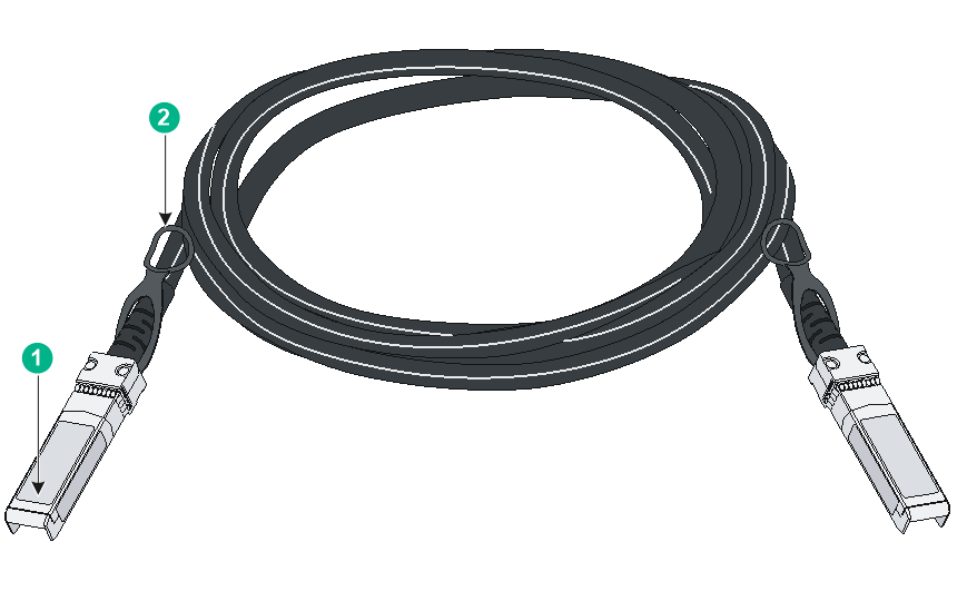
|
(1) Connector |
(2) Latch |
LEDs
System LED
Through the system status LED, you can preliminarily determine the working state of the switch. For more information, see Table 29.
Table 29 System LED description
|
LED mark |
Status |
Description |
|
SYS |
Flashing green |
The switch has started up correctly. |
|
Flashing red |
The switch is starting up. |
|
|
Off |
The switch is powered off or has not started up correctly. |
Port mode LED
For models providing a mode switch button for the port mode LED, you can use the button and the port status LEDs to view the port operational status from various angles and obtain more device information.
· The port mode LED informs users about the specific type of information displayed by the port status LEDs for various types of ports.
· You can press the mode switch button for the port mode LED to adjust the display state of the LED, thereby ultimately controlling the information displayed by the port status LEDs.
Table 30 Port mode LED description
|
LED mark |
Status |
Description |
|
MODE |
Steady green |
The port LEDs indicate the Link/Active status of ports. |
|
Flashing green (only for PoE models) |
The port LEDs indicate the PoE power supply status of the ports. |
10G/5G/2.5G/1000/100BASE-T Ethernet port LED
Table 31 10G/5G/2.5G/1000/100BASE-T Ethernet port LED description
|
LED status |
Description |
|
Steady green |
A link is present on the port and the port is operating at 10 Gbps. |
|
Flashing green |
The port is sending or receiving data at 10 Gbps. |
|
Steady yellow |
A link is present on the port and the port is operating at 100 Mbps, 1 Gbps, 2.5 Gbps, or 5 Gbps. |
|
Flashing yellow |
The port is sending or receiving data at 100 Mbps, 1 Gbps, 2.5 Gbps, or 5 Gbps. |
|
Off |
No link is present on the port. |
2.5G/1000/100BASE-T Ethernet port LED
Table 32 2.5G/1000/100BASE-T Ethernet port LED description
|
LED status |
Description |
|
Steady green |
A link is present on the port and the port is operating at 2.5 Gbps, 1000 Mbps, or 100 Mbps. |
|
Flashing green |
The port is sending or receiving data at 2.5 Gbps, 1000 Mbps, or 100 Mbps. |
|
Off |
No link is present on the port. |
10/100/1000BASE-T autosensing Ethernet port LED
For the ES4200 series switches except ES4200-4UMG2X and ES4200-24T2X:
· For models providing a mode switch button for the port mode LED, you can use the button and the Ethernet port LEDs to view the port operational status from various angels. For more information, see Table 33.
· For models not providing a mode switch button, see Table 34 to view the Ethernet port LED description.
For the ES4200-4UMG2X and ES4200-24T2X switches, see Table 35.
Table 33 Description of the 10/100/1000BASE-T autosensing Ethernet port LED (1)
|
LED |
Description |
|
|
Port mode LED (MODE) |
Ethernet port LED |
|
|
Steady green (Link/Active) |
Steady green |
A link is present on the port. |
|
Flashing green |
The port is receiving or sending data. |
|
|
Off |
No link is present on the port. |
|
|
Flashing green (PoE mode, only supported by PoE models) |
Steady green |
PoE power supply is normal. |
|
Off |
The port is not connected to a PD or PoE is not enabled on the port. |
|
Table 34 Description of the 10/100/1000BASE-T autosensing Ethernet port LED (2)
|
LED status |
Description |
|
Steady green |
A link is present on the port. |
|
Flashing green |
The port is receiving or sending data. |
|
Off |
No link is present on the port. |
Table 35 Description of the 10/100/1000BASE-T autosensing Ethernet port LED (3)
|
Ethernet port LED |
Status |
Description |
|
Speed LED |
Steady green |
A link is present on the port. |
|
Flashing green |
The port is receiving or sending data. |
|
|
Off |
No link is present on the port. |
|
|
PoE LED |
Steady yellow |
PoE is operating correctly. |
|
Off |
The port is disconnected or PoE is disabled. |
SFP/SFP+ port LED
Table 36 SFP/SFP+ port LED description
|
LED status |
Description |
|
Steady green |
A link is present on the port. |
|
Flashing green |
The port is receiving or sending data. |
|
Off |
· No link is present on the port. · The mode LED is operating in PoE mode (available only for PoE switch models). |