- Table of Contents
- Related Documents
-
| Title | Size | Download |
|---|---|---|
| 01-Text | 253.52 KB |
Connecting to the 5G network at uplink and Ethernet endpoints at downlink
Connecting to the 5G network at uplink and Wi-Fi endpoints at downlink
Connecting to the 5G network at uplink and multiple types of endpoints at downlink
Powering on the device for the first time
Logging in to the device through the console port
Logging in to the device through Telnet
Logging in to the device through the web interface
Verifying the current operating mode of the AP
Switching the AP operating mode
Example for verifying and switching the AP operating mode
Configuring external network settings
Configuring Ethernet LAN settings
Quick configuration guide
This configuration guide describes how to quickly configure the H3C CPE5100P 5G Customer Premises Equipment in cloud mode, including configuration prerequisites, planning, procedures, and verification. In this manual, CPE represents H3C CPE5100P.
Product overview
The H3C CPE5100P is an indoor 5G wireless data endpoint. It uses 5G access technologies to provide conversion between 5G wireless communication data and Ethernet or WLAN data, allowing devices with only WLAN or Ethernet capabilities to access the 5G wireless communication network. Compliant with 3GPP-R15, the CPE5100P can implement all features on the RRC, SDAP, PDCP, RLC, MAC, and PHY layers. It can provide uplink connectivity to a 5G base station from the 5G radio interface and downlink connectivity to customer endpoints through Ethernet and Wi-Fi ports.
The CPE5100P can be used not only in business scenarios including industrial campus, transportation, energy, and manufacturing, but also in customer scenarios such as offices and homes.
Networking modes
The CPE provides multiple interfaces and features to support various service scenarios. The CPE supports multiple types of networks (including Ethernet, mobile communication, and Wi-Fi) at the uplink and multiple types of endpoints (including Ethernet, and Wi-Fi) at the downlink. When selecting a networking mode for CPE, consider the interface and feature restrictions.
Table 1 Uplink and downlink connections supported by CPE
|
Port |
Uplink connection |
Downlink connection |
|
NR antenna port |
NR or LTE network |
- |
|
Wi-Fi antenna port |
Wi-Fi network |
Wi-Fi endpoint |
|
GE RJ-45 port |
Ethernet |
Ethernet endpoint |
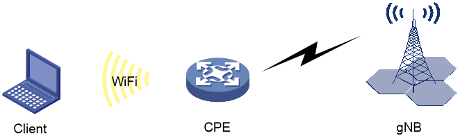
Connecting to the 5G network at uplink and Ethernet endpoints at downlink
The CPE accesses the 5G network through an NR antenna. An Ethernet endpoint can connect to the CPE through a GE port to access the external network through the 5G network.
Figure 1 Connecting to the 5G network at uplink and Ethernet endpoint at downlink

Connecting to the 5G network at uplink and Wi-Fi endpoints at downlink
The CPE accesses the 5G network through an NR antenna. A wireless client can connect to the CPE through a Wi-Fi antenna to access the external network through the 5G network.
Figure 2 Connecting to the 5G network at uplink and Wi-Fi endpoints at downlink
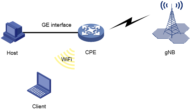
Connecting to the 5G network at uplink and multiple types of endpoints at downlink
The CPE accesses the 5G network through an NR antenna. An Ethernet endpoint can connect to the CPE through a GE port to access the external network through the 5G network. A wireless client can connect to the CPE through a Wi-Fi antenna to access the external network through the 5G network.
Figure 3 Connecting to the 5G network at uplink and multiple types of endpoints at downlink
Quick configuration workflow
|
|
TIP: In site scenarios, configure service settings as needed. This guide uses external network, Ethernet LAN, and WLAN configuration as an example. |
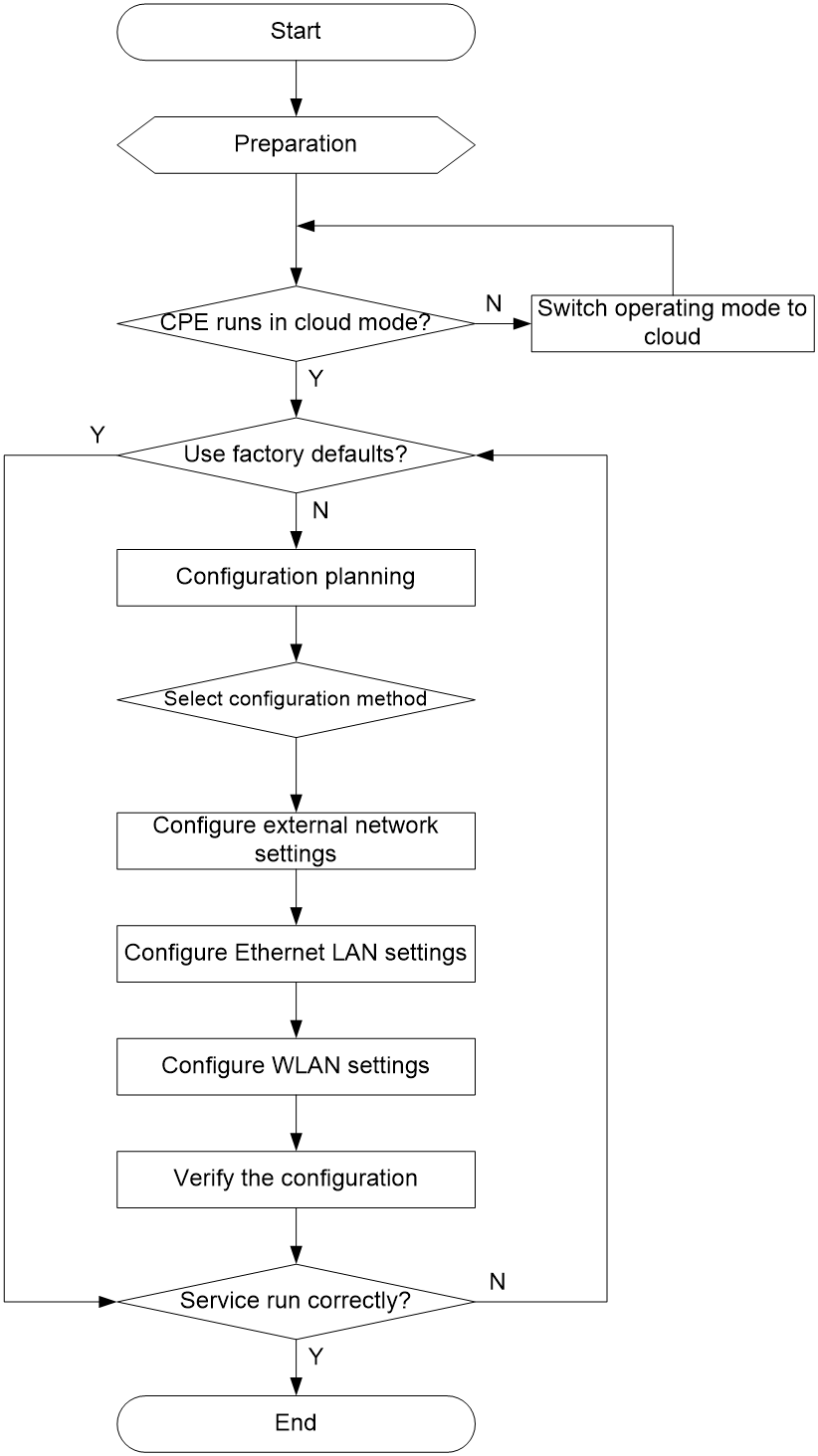
Figure 4 shows the quick configuration workflow for a CPE in cloud mode. For more information about the cloud mode, see "AP operating modes."
Figure 4 Quick configuration workflow
Prerequisites
Before the configuration, make sure the device is installed correctly and accessible.
Installing the device
The CPE5100P can be mounted to a desktop or ceiling. You might also need to install SIM cards and antennas. For more information about device installation, see H3C CPE5100P 5G Customer Premises Equipment Installation Guide.
Logging in to the device
Powering on the device for the first time
|
|
NOTE: By default, the device operates in fit mode. You can switch the operating mode of the CPE5100P between fit and cloud as needed. |
When the device is powered on for the first time, you can directly log in to the device through the console port. Local login through the console port is the basic login method and basis of other login methods. To remotely log in to the device through Telnet or the web interface, you must first obtain the IP address of the device. Remote login through the web interface is supported only when the device operates in cloud mode.
Logging in to the device through the console port
Setting up the configuration environment
|
|
NOTE: The device provides console access through the mini USB console port, which requires a USB configuration cable. Before the configuration, access the H3C official website (www.h3c.com/en) to download the USB console driver program. |
To connect to the CPE through a USB configuration cable:
1. Connect the USB port end to the PC.
2. Connect the other end to the console port on the CPE.
Configuring endpoint parameters
To set up a local configuration environment through the console port, you must use a terminal emulation program, such as HyperTerminal or PuTTY, to establish a connection with the router. You can run terminal emulation programs to connect to network devices or access sites through Telnet or SSH. For more information about how to use terminal emulation programs, see the programs' user guides.
Configure the terminal parameters as follows:
· Baud rate—9600.
· Data bits—8.
· Stop bits—1.
· Parity—None.
· Flow control—None.
Logging in to the device through the console port
After the device starts up, the PC terminal screen displays the following information:
System is starting...
Booting Normal Extend BootWare.
……
System application is starting...
Startup configuration file does not exist.
User interface con0 is available.
Press ENTER to get started.
Logging in to the device through Telnet
By default, Telnet is enabled on the device, and the default login information is as follows:
· Username: admin
· Password: h3capadmin
· Management IP address (non-fit mode): 192.168.8.1/24
|
|
NOTE: · By default, interface VLAN-interface 1 of the device can obtain an IP address through DHCP. When a DHCP server is deployed in the network, the CPE preferentially obtains an IP address through DHCP. · If the device operates in cloud mode and cannot obtain an IP address automatically, the device uses 192.168.8.1/24. · To view the IP address of interface VLAN-interface 1, log in to the device through the console port, and then execute the display ip interface brief command in any view. |
Logging in to the device through a wired network
By default, you can log in to the device through a wired network when the device operates in fit or cloud mode.
To log in to the device through a wired network by using the default login information:
1. Connect the maintenance endpoint to the GE1/PoE_IN or GE2/PoE_OUT port on the device.
2. Configure an IP address for the maintenance endpoint, and make sure the maintenance endpoint and interface VLAN-interface 1 on the device can reach each other.
3. On the maintenance terminal, start the terminal emulation program (such as HyperTerminal or PuTTY), select the Telnet option, and then enter the device's management IP address, username, and password.
Logging in to the device through a wireless network
|
|
NOTE: Configure the wireless client to dynamically obtain an IP address. Some Intel NICs might not be compatible with the 802.11ax mode. To successfully detect Wi-Fi 6 wireless networks, upgrade the NIC drivers to the latest version as a best practice. For more information, see the related document at the Intel offcial website. |
By default, you can log in to the device through a wireless network when the device operates in cloud mode.
To log in to the device through a wireless network by using the default login information:
1. Enable Wi-Fi on the wireless client. Search for and connect to the Wi-Fi named H3C_WiFi_1.
2. Execute the telnet wlan.h3c.com command on the CLI of the wireless terminal.
3. Enter the default username and password, and change the password as needed upon prompt.
Logging in to the device through the web interface
|
|
IMPORTANT: You can log in to the device through the web interface only when the device operates in cloud mode. |
The device supports both HTTP and HTTPS.
By default, HTTP and HTTPS are enabled on the device, and the default login information is as follows:
· Username: admin
· Password: h3capadmin
· Role: network-admin
· Management IP address (non-fit mode): 192.168.8.1/24
|
|
NOTE: · By default, interface VLAN-interface 1 of the device can obtain an IP address through DHCP. When a DHCP server is deployed in the network, the CPE preferentially obtains an IP address through DHCP. · If the device operates in cloud mode and cannot obtain an IP address automatically, the device uses 192.168.8.1/24. · To view the IP address of interface VLAN-interface 1, log in to the device through the console port, and then execute the display ip interface brief command in any view. |
Logging in to the device web interface through a wired network
To log in to the device web interface through a wired network by using the default login information:
1. Connect the maintenance endpoint to the GE1/PoE_IN or GE2/PoE_OUT port on the device.
2. Configure an IP address for the maintenance endpoint, and make sure the maintenance endpoint and interface VLAN-interface 1 on the device can reach each other.
3. On the maintenance endpoint, enter the management IP address of the device in the address bar of a browser, and press Enter to access the local web management interface of the device. If HTTP is used, the URL is in the http://ip-address:80 format, where http:// can be omitted. If HTTPS is used, the URL is in the https://ip-address:443 format. ip-address represents the management IP address of the device. Port numbers 80 and 443 are the default port numbers for HTTP and HTTPS, respectively, and can be omitted.
4. Click Log In. Change the login password upon the prompt as needed, and then click OK.
Logging in to the device web interface through a wireless network
|
|
NOTE: By default, Wi-Fi service with SSID H3C_WiFi_1 is enabled on the device. Some Intel NICs might not be compatible with the 802.11ax mode. To successfully detect Wi-Fi 6 wireless networks, upgrade the NIC drivers to the latest version as a best practice. For more information, see the related document at the Intel offcial website. |
To log in to the device web interface through a wireless network by using the default login information:
1. Enable Wi-Fi on the wireless client. Search for and connect to the Wi-Fi named H3C_WiFi_1, where XXXXXX is the last six digits of the device's MAC address.
2. On the wireless endpoint, enter http://wlan.h3c.com in the address bar of a browser, and then press Enter to open the device login page.
3. Enter the default username and password, and then click Log In. Change the login password as needed upon the prompt, and then click OK.
Logging out of the web interface
For security purposes, log out of the web interface immediately after you finish your tasks.
To log out of the web interface, click admin on the top right of the page, and then select Log Out.
The system does not save the running configuration automatically when you log out of the web interface. As a best practice, use either of the following methods to save the running configuration before logging out of the web interface:
· Click Save on the top right of the page, and then click Yes in the dialog box that opens.
· From the left navigation pane, select System > Management > Configuration. Click Save Running Configuration, select to the next-startup configuration file, and then click Apply.
Factory defaults
About factory defaults
A device typically comes with some basic settings known as factory defaults. To enable users to use the CPE with minimal or no configuration in common network scenarios, the CPE comes with external network, Ethernet LAN, and WLAN settings. To display these factory defaults, execute the display default-configuration command.
# Execute the display default-configuration command in any view to display the factory defaults.
<system> display defualt-configuration
Using factory defaults
When setting up a new network, first verify whether the factory defaults meet the service requirements. Use the factory defaults if they meet the requirements. Configure the network settings as needed if the factory defaults do not meet the requirements.
Restoring factory defaults
|
|
TIP: The configuration of a mobile communication modem is generally stored in the modem's non-volatile storage medium. Executing the restore factory-default command can restore only some of the modem's configuration to the default, including: · Network connection mode (mode command); · LTE operating band (lte band command); · NR operating band (nr band command); · Mobile network selection mode (plmn select command). |
Restoring factory defaults from the CLI of CPE
After logging into the CPE CLI, you can execute the restore factory-default command to restore the factory defaults. Executing this command will force the device to reboot for the changes to take effect.
<Sysname> restore factory-default
This command will restore the system to the factory default configuration and cl
ear the operation data, and forcibly reboot the system. Continue [Y/N]:y
Please reboot the system to place the factory default configuration into effect.
Please wait....Done.
The system is rebooting...
To start up the device with factory defaults, execute the undo startup saved-configuration command in user view. This command does not restore the defaults of the mobile communication modem. This command requires a device restart to take effect.
<System> undo startup saved-configuration
Please wait...... Done.
<System> reboot
art to check configuration with next startup configuration file, please wait..
.......DONE!
Current configuration may be lost after the reboot, save current configuration?
[Y/N]:n
This command will reboot the device. Continue? [Y/N]:y
Now rebooting, please wait...
Restoring factory defaults from the web interface of CPE
1. Log in to the CPE web interface.
2. From the navigation pane, select System > Management > Configuration.
3. Click the ![]() icon
on the right of Reset to factory
defaults, click Reset, and then click Yes in the
dialog box that opens. The device will be forcibly
restarted after you restore its factory defaults.
icon
on the right of Reset to factory
defaults, click Reset, and then click Yes in the
dialog box that opens. The device will be forcibly
restarted after you restore its factory defaults.
AP operating modes
About AP operating modes
|
|
NOTE: The CPE5100P can act as an AP. In this section, AP and CPE share the same description and topology icon. By default, the CPE5100P operates in fit mode. |
The CPE supports Wi-Fi 6 and can operate in fit or cloud mode. You can switch the operating mode for the CPE without the need to obtain the image file for an operating mode.
· Fit—The AP is managed and controlled by an AC.
· Cloud—The AP can operate independently or managed by Cloudnet. A cloud AP not managed by Cloudnet can act as a fat AP.
Verifying the current operating mode of the AP
To configure CPE services in cloud mode, you must first verify that the CPE is operating in cloud mode. You can verify the operating mode of a CPE by using one of the following methods:
· AP CLI: Log in to the CPE through the console port, and then execute the display wlan device role command in any view.
· AP BootWare menu:
a. During the AP startup or restart process, press Ctrl+B to enter the BootWare main menu when the system prompts Press Ctrl+B to access EXTENDED-BOOTWARE MENU...
b. Press Ctrl+Y to enter the AP operating mode switchover menu.
· AC CLI: When the AP is managed by an AC, you can verify the AP operating mode through the AC CLI. This mode is applicable to APs operating in fit or cloud mode.
· AP's default wireless service: An AP in cloud mode comes with a default wireless service with SSID H3C. After the AP starts up, enable the Wi-Fi service of a wireless terminal. If the terminal can detect this wireless service, the AP is operating in cloud mode. Given the many uncertainties at the site, this method is generally used as an auxiliary verification method.
Switching the AP operating mode
|
|
NOTE: The CPE saves the configuration files for the fit mode and cloud mode in different paths, so it can start up with different configuration files in different operating modes. If you execute the wlan ac ip command for a CPE operating in cloud mode, save the configuration, and then switch the operating mode to fit by using the ap-mode command, the CPE will also save the configuration of the wlan ac ip command into the configuration file for fit mode. |
You need to switch the AP operating mode if the CPE operates in fit mode. You can switch the operating mode of the CPE through the methods shown in Table 2.
Table 2 AP operating mode switching methods
|
Current operating mode |
Available operating modes that can be switched to |
Operating mode switching method |
|
FIT |
Cloud |
Switching the operating mode for an AP from the CLI of the AC |
|
Switching the operating mode for an AP from the CLI of the AP |
||
|
Switching the operating mode from the BootWare menu of the AP |
||
|
Cloud |
FIT |
Switching the operating mode for an AP from the CLI of the AC |
|
Switching the operating mode for an AP from the CLI of the AP |
||
|
Switching the operating mode from the BootWare menu of the AP |
Example for verifying and switching the AP operating mode
|
|
NOTE: The output information from the commands might vary by software version. |
This section uses the AP BootWare menu method to switch the AP operating mode.
# Log in to the device through the console port, and then execute the reboot command to restart the AP. Then, the system will display the following information:
<System> reboot
Start to check configuration with next startup configuration file, please wait..
.......DONE!
This command will reboot the device. Continue? [Y/N]:y
Now rebooting, please wait...
%Apr 11 23:36:57:760 2021 H3C DEV/5/SYSTEM_REBOOT: System is rebooting now.
System is starting...
Press Ctrl+D to access BASIC-BOOTWARE MENU...
Booting Normal Extended BootWare
The Extended BootWare is self-decompressing..................Done.
***********************************************************************
* *
* H3C CPE5100P BootWare, Version 1.04 *
* *
***********************************************************************
Copyright (c) 2004-2022 New H3C Technologies Co., Ltd.
Compiled Date : Jun 23 2022
Memory Type : DDR4 SDRAM
Memory Size : 1024MB
Flash Size : 512MB
PCB Version : Ver.B
BootWare Validating...
Press Ctrl+B to access EXTENDED-BOOTWARE MENU...
# Press Ctrl+B to enter the BootWare main menu when the system prompts Press Ctrl+B to access EXTENDED-BOOTWARE MENU...:
Password recovery capability is enabled.
Note: The current operating device is flash
Enter < Storage Device Operation > to select device.
==========================<EXTENDED-BOOTWARE MENU>======================
|<1> Boot System |
|<2> Enter Serial SubMenu |
|<3> Enter Ethernet SubMenu |
|<4> File Control |
|<5> Restore to Factory Default Configuration |
|<6> Skip Current System Configuration |
|<7> BootWare Operation Menu |
|<8> Skip Authentication for Console Login |
|<9> Storage Device Operation |
|<0> Reboot |
=======================================================================
Ctrl+Z: Access EXTENDED ASSISTANT MENU
Ctrl+F: Format File System
Ctrl+C: Display Copyright
Ctrl+Y: Change AP Mode
Enter your choice(0-9):
# Press Ctrl + Y at the main menu.
Please select the new mode
Current mode is Fit Mode
=======================================================================
|NO. Mode |
|1 Fit Mode |
|2 Cloud Mode |
|0 Exit |
=======================================================================
# Select a number as needed. The switching is successful when the following message is displayed.
Enter your choice(0-2):2
Changed to cloud mode successfully!
==========================<EXTENDED-BOOTWARE MENU>==========================
|<1> Boot System |
|<2> Enter Serial SubMenu |
|<3> Enter Ethernet SubMenu |
|<4> File Control |
|<5> Restore to Factory Default Configuration |
|<6> Skip Current System Configuration |
|<7> BootWare Operation Menu |
|<8> Skip Authentication for Console Login |
|<9> Storage Device Operation |
|<0> Reboot |
============================================================================
Ctrl+Z: Access EXTENDED ASSISTANT MENU
Ctrl+F: Format File System
Ctrl+C: Display Copyright
Ctrl+Y: Change AP Mode
# Enter 0 at the BootWare main menu to restart the device.
Enter your choice(0-9):0
Configuration planning
About configuration planning
Configuration planning is the process where you plan the network topology and data in advance based on the service needs. Configuration planning is necessary when the factory defaults do not meet the service needs. This guide describes the configuration of the CPE in cloud mode.
Restrictions and guidelines
Data used in the configuration plan is for illustration only. You can change the data in site scenarios as needed.
Network topology planning
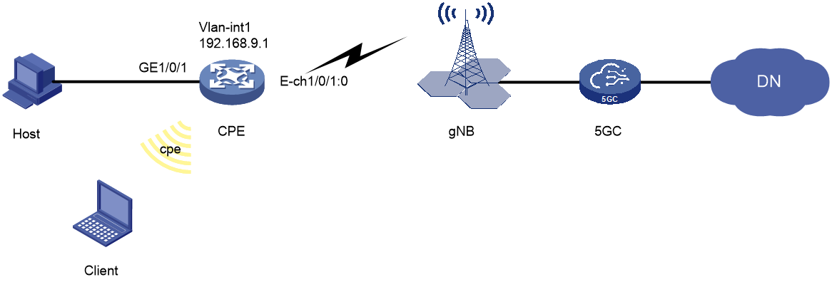
Figure 5 is a typical topology diagram of CPE configuration in cloud mode, where CPE accesses the 5G network through Ethernet channel interface Eth-channel 1/0/1:0, accesses the host through Ethernet interface GE1/0/1, and accesses the client through Wi-Fi network with SSID cpe. Both the host and client can access the external network through CPE.
Figure 5 Topology diagram of CPE configuration in cloud mode
Data planning
About data planning
Data planning includes planning for external network data, Ethernet LAN data, WLAN data, and other data.
External network data planning
External network data planning determines the mode and method for accessing the external network. The CPE can use an NR antenna to receive 5G/4G network signals and access the external network through the 5G/4G network. The CPE can also access the external network through an Ethernet interface or Wi-Fi network. This example plans one WAN line for access to the external network through the 5G network, as shown in Table 3.
Table 3 External data planning
|
Category |
Subcategory |
Example |
Description |
|
WAN interface |
Eth-channel1/0/1:0 |
Obtain IPv4 and IPv6 addresses by using the modem-manufacturer's proprietary protocol |
This plan uses the factory default configuration. |
|
Scenario |
- |
Single-WAN scenario |
- |
|
Line 1 |
WAN port |
SIM1(Cellular1/0/1) |
Access the mobile communication network through the NR antenna |
|
Carrier |
User-defined: · APN: test · Username: - · Password: - · Authentication mode: PAP or CHAP |
In this plan, it is assumed that the carrier's APN needs to be set to test. |
|
|
System mode |
AUTO |
This plan uses the factory default configuration, and the mobile communication modem automatically selects a network. |
|
|
NAT |
Enabled |
- |
|
|
Dial-up parameters |
Auto-dial: Enabled |
In the current software version, the dial-up parameters cannot be configured on the web interface. This example uses the factory default configuration. |
Ethernet LAN data planning
The CPE provides a GE interface for Ethernet terminal access. Ethernet LAN data planning mainly describes how to access Ethernet terminals through the GE interface and how to provide services for Ethernet terminals.
Table 4 Ethernet LAN data planning
|
Category |
Subcategory |
Example |
Description |
|
Ethernet LAN interfaces |
GE1/0/1 |
· Bridge mode · VLAN: 1 |
N/A |
|
GE1/0/2 |
· Bridge mode · VLAN: 1 |
Not used in this example |
|
|
Vlan-interface1 |
IP address: 192.168.9.1/24 |
N/A |
|
|
Layer 3 IP services |
DHCP |
Enabled |
N/A |
|
DHCP address pool |
· IP address segment: 192.168.9.0/24 · IP address range: 192.168.9.2 to 192.168.9.254 · Gateway: 192.168.9.1 · DNS servers: 192.168.9.1, 114.114.114.114 |
Assign IP addresses to downlink Ethernet terminals |
|
|
DNS proxy |
Enabled |
N/A |
WLAN data planning
The CPE supports Wi-Fi 6, providing wireless network access to Wi-Fi terminals through Wi-Fi antennas. WLAN data planning describes how to connect to Wi-Fi terminals through the Wi-Fi network and how to provide wireless services to them.
Table 5 WLAN data planning
|
Category |
Subcategory |
Example |
Description |
|
WLAN interfaces |
Radio 1/0/1 |
· Frequency band: 5GHZ · VLAN: 1 · Bound wireless service: 20 |
N/A |
|
Radio 1/0/2 |
· Frequency band: 2.4GHZ · VLAN: 1 · Bound wireless service: 20 |
N/A |
|
|
Wireless service |
Wireless service name |
20 |
Adding a wireless service |
|
SSID |
cpe |
You can use the factory default wireless service with SSID H3C_WiFi_1. In this example, a new wireless service with SSID cpe is configured. |
|
|
Wireless service |
Enabled |
N/A |
|
|
Default VLAN |
1 |
N/A |
|
|
Authentication mode |
Static PSK authentication |
Enable the clients to access the WLAN through the encryption mode |
|
|
Security mode |
WPA2 |
||
|
Cipher suite |
CCMP |
||
|
Key type |
Passphrase (enter a character string as the key) |
||
|
Key |
password |
Other data planning
Besides the data planning mentioned above, you can also perform data planning for routing,and time synchronization as needed. This guide does not describe these data plans, you can use the factory defaults or ignore these data plans.
Procedures
Using the CLI
You can log in to the CPE CLI through the console port or Telnet.
Configuring external network settings
# Configure a 5G modem parameter template, and set the access point to test.
<CPE> system-view
[CPE] apn-profile 1
[CPE-apn-profile-1] apn static test
[CPE-apn-profile-1] quit
# Configure interface Eth-channel1/0/1:0 to use the 5G modem parameter template.
[CPE] interface eth-channel 1/0/1:0
[CPE-Eth-channel1/0/1:0] apn-profile apply 1
[CPE-Eth-channel1/0/1:0] quit
Configuring Ethernet LAN settings
# Configure DHCP address pool 1.
[CPE] dhcp server ip-pool 1
[CPE-dhcp-pool-pool1] network 192.168.9.0 mask 255.255.255.0
[CPE-dhcp-pool-pool1] gateway-list 192.168.9.1
[CPE-dhcp-pool-pool1] dns-list 192.168.9.1 114.114.114.114
|
|
NOTE: 114.114.114.114 is the IP address of the DNS server. |
# Configure an IP address for VLAN-interface 1, and bind the interface to DHCP address pool 1.
[CPE] interface vlan-interface 1
[CPE-Vlan-interface1] ip address 192.168.9.1 255.255.255.0
[CPE-Vlan-interface1] dhcp server apply ip-pool 1
[CPE-Vlan-interface1] quit
|
|
NOTE: Changing the IP address of CPE's interface VLAN-interface 1 might cause the connection between the maintenance terminal and the interface to disconnect. In this scenario, you can log in to the device through the console port, or re-log in to the device through Telnet by using the new IP address of VLAN-interface 1. |
Configuring WLAN settings
|
|
TIP: · If no other wireless services are required (such as factory-default H3C_WiFi_1), you can execute the undo service-template enable command in wireless service template view to disable those wireless services. · You can also change the SSID to cpe by directly editing the original wireless service SSID. |
# Create wireless service template 20, and set its SSID to cpe.
[CPE] wlan service-template 20
[CPE-wlan-st-20] ssid cpe
# Specify the PSK AKM mode, and set the PSK to password in plain text.
[CPE-wlan-st-20] akm mode psk
[CPE-wlan-st-20] preshared-key pass-phrase simple password
# Specify the cipher suite as CCMP and the security IE as RSN.
[CPE-wlan-st-20] cipher-suite ccmp
[CPE-wlan-st-20] security-ie rsn
# Enable the wireless service template.
[CPE-wlan-st-20] service-template enable
[CPE-wlan-st-20] quit
# Bind wireless service template 20 to interface WLAN-Radio 1/0/1.
[CPE] interface wlan-radio 1/0/1
[CPE-WLAN-Radio1/0/1] undo shutdown
[CPE-WLAN-Radio1/0/1] service-template 20
[CPE-WLAN-Radio1/0/1] quit
# Bind wireless service template 20 to interface WLAN-Radio 1/0/2.
[CPE] interface wlan-radio 1/0/2
[CPE-WLAN-Radio1/0/1] undo shutdown
[CPE-WLAN-Radio1/0/1] service-template 20
[CPE-WLAN-Radio1/0/1] quit
Saving the configuration
# Save the configuration.
[CPE] save
The current configuration will be written to the device. Are you sure? [Y/N]:y
Please input the file name(*.cfg)[flash:/startup.cfg]
(To leave the existing filename unchanged, press the enter key):
flash:/startup.cfg exists, overwrite? [Y/N]:y
Validating file. Please wait...
Saved the current configuration to mainboard device successfully.
Verifying the configuration
Verify that the host can access the CPE through Ethernet to access the external network, and the client can access the CPE through Wi-Fi to access the external network.