- Table of Contents
- Related Documents
-
| Title | Size | Download |
|---|---|---|
| 01-Text | 712.96 KB |
Restrictions and guidelines for service planning
Network topology and IP address planning
Logging in to the vSCN web management interface
Logging in to the web management interface for the first time
Logging out of the web management interface
vSCN feature configuration restrictions and guidelines
Configuring the vSCN basic services
Configuring the human-machine command interaction feature
Setting the host name for each network element
Configuring IP addresses for interfaces
Saving the basic service configuration
(Optional) Configuring the vSCN voice services
Configuring IP addresses for interfaces
Configuring the voice service features of AMF
Configuring the voice service features of SMF
Configuring the voice service features of PCF
Configuring the voice service features of UDR
Configuring the voice service features of external IMS
Configuring the voice service features of proprietary vIMS integration
Saving voice service configuration
(Optional) Verifying voice services
vSCN service activation guide
Overview
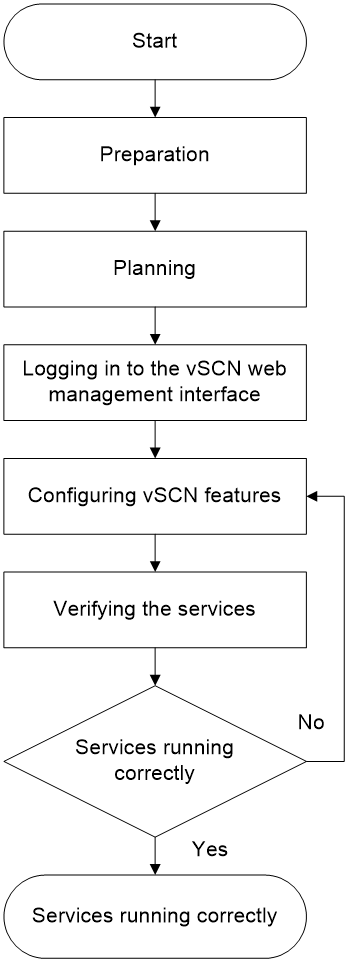
The vSCN5100 core network service activation includes preparation, planning, logging in to the vSCN web management interface, configuring vSCN features, and service verification. Unless otherwise noted, the guide uses vSCN to represent H3C vSCN5100.
The vSCN services include basic services and voice services. This guide only describes the configuration of vSCN basic services and the configuration of voice services on vSCN.
|
|
NOTE: This guide only describes how to activate services through the vSCN Web. If the vSCN is connected to IMC, you can also activate services through IMC. To deploy vSCN configuration through IMC, make sure the following configuration has been deployed through the vSCN CLI. · Use the sftp server enable command to enable the SFTP server feature. · Use the restful http enable and restful https enable commands to enable RESTful features based on HTTP/HTTPS. |
Service activation process
Figure 1 Service activation process
Preparation
Activation preparation primarily involves installing vSCN, configuring the web manager login IP address, and obtaining a license. For specific methods to install vSCN and configure the web manager login IP address, see H3C vSCN5100 Intelligent Core Network Installation Guide.
For quantity-based licenses, after activating licenses through the License Server, you must also request available licenses on each network element's licensing page. Otherwise, the License Server will not issue licenses to connected network elements. For specific methods on how to request available licenses on the licensing pages of each network element, see license configuration for each element in "Configuring the vSCN basic services."
|
|
NOTE: After installing vSCN, if the software does not run correctly, first check if the installation process was correct. If the problem persists, contact H3C Support. |
Planning
Introduction
Service planning involves network topology, IP address, and data planning in advance based on user requirements. This guide will outline the method for activating vSCN services.
Restrictions and guidelines for service planning
H3C's activation plan includes the following IPv4 address sections:
· 10.20.0.0/24
· 10.20.1.0/24
· 10.20.2.0/24
· 10.20.3.0/24
· 10.20.4.0/24
· 10.20.5.0/24
· 10.30.0.0/24
· 199.23.1.0/24
· 199.23.2.0/24
· 60.60.60.0/24
· 70.70.70.0/24
You can edit the IPv4 address sections as needed. For example, if IPv4 address 10.20.1.0/24 is already in use on the live network, you can specify an unused IPv4 address section.
Network topology and IP address planning
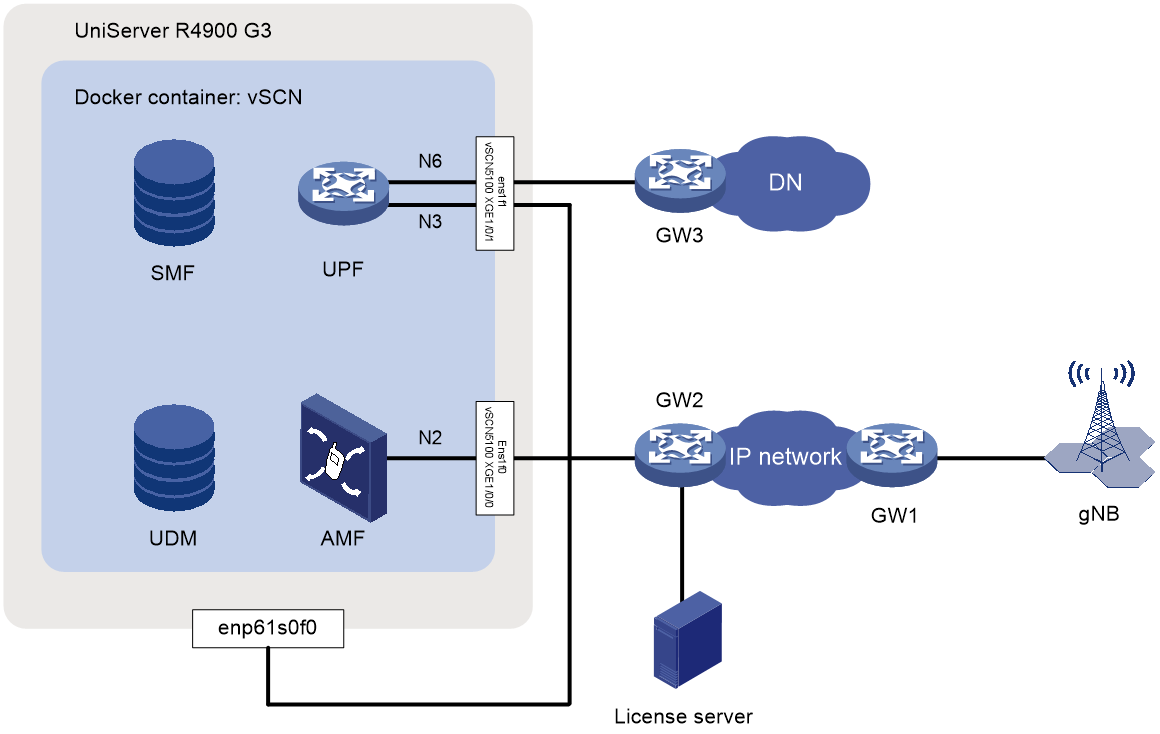
Figure 2 shows a typical topology for vSCN. To aid understanding, the diagram shows three gateway devices: GW1, GW2, and GW3. When building an actual network, you can use one Layer 3 network device to replace GW1, GW2, and GW3. Connect the server interfaces to the network devices by using based on the actual topology.
|
|
NOTE: This document illustrates a typical vSCN topology, as shown in Figure 2, using the example of vSCN installed on a UniServer R4900 G3 server. The procedure for activating vSCN services in a VM environment is the same as in a physical device environment, and will not be repeated here. Figure 2 shows a typical vSCN topology, displaying only some of the network elements within the vSCN. Elements such as the PCF are not shown within the container. In this example, the License Server is installed on the host server. |
Figure 2 vSCN typical topology
|
Device |
Interface |
IP address |
Remarks |
|
License Server |
- |
10.20.1.20/24 |
Install the License Server on a standalone server or the UniServer R4960 G3 that hosts vSCN. To ensure successful registration of the vSCN software, make sure the License Server and vSCN are reachable to each other. |
|
Use Docker containers. |
- |
10.20.1.30/24 |
· Used for logging in to the web management interface. · Used for communication between vSCN and the License Server. · Used for communication with the network management system (NMS). The NMS connects to the vSCN through the vSCN5100's IP address, username, and password. · Use the default username emsadmin and password cg5*@cNc3h to connect the NMS to the vSCN5100. |
|
N2 |
10.20.2.10/24 |
Used to connect the base station and AMF, transmitting control plane data. |
|
|
N3 |
10.20.3.10/24 |
Used to transmit user-plane data between the base station and the core network. |
|
|
N6 |
10.20.4.10/24 |
Use this feature to send and receive user plane data between the core network and the DN. |
|
|
Rx |
10.20.5.10/24 |
Used to connect IWF and IMS, involving only voice services which are not shown in the network diagram. |
|
|
Host |
Management |
10.20.1.20/24 |
Used to log in and manage H3Linux. When the License Server is installed on the same server as vSCN, this address can serve as the License Server's address. In this example, the host's management IP address is the same as the License Server's address. |
|
GW1 |
- |
199.23.1.1/24 |
Gateway IP address of the N2 interface on the base station side. |
|
- |
199.23.2.1/24 |
Gateway IP address of the N3 interface on the base station side. |
|
|
GW2 |
- |
10.20.1.1/24 |
Gateway IP address of the License Server. |
|
10.20.2.1/24 |
Gateway IP address of the AMF N2 interface. |
||
|
10.20.3.1/24 |
Gateway IP address of the UPF N3 interface. |
||
|
GW3 |
- |
10.20.4.1/24 |
Gateway IP address of the UPF N6 interface. |
|
|
10.20.5.1/24 |
Gateway IP address of the IWF Rx interface. |
|
|
IMS |
- |
10.30.0.10/24 |
Used to connect to the IWF Rx interface, which is only relevant for voice services and is not shown in the network diagram. |
|
- |
10.30.0.11/24 |
Used to connect the UPF N6 interface, which is only relevant for voice services and not shown in the network diagram. |
|
|
gNB |
|
· Base station side N2 interface IP address: 199.23.1.2/24 · Base station side N3 interface IP address: 199.23.2.2/24 |
Base station IP addresses |
|
UE |
- |
60.60.60.1/24 to 60.60.60.30/24 |
IP address allocated to UE to access DN. |
|
- |
70.70.70.1/24 to 70.70.70.30/24 |
IP address allocated to UE to access IMS. |
Data planning
Introduction
Data planning includes both base station and core network data planning. It involves Mobile Country Code (MCC), Mobile Network Code (MNC), Tracking Area Code (TAC), carrier ID, base station ID, and physical cell ID.
Base station data planning
Base station data planning depends on the networking mode of the base station BBU and RRU, CPRI port number, the number of transmit and receive channels, and the transmit and receive modes. This guide does not provide detailed information; for more information, please refer to the base station product's service activation guide. Note that the planning data for the base station must meet the requirements of Table 1.
Table 1 Base station data planning
|
Parameter |
Value description |
|
MCC |
Must be consistent with the core network |
|
MNC |
|
|
TAC |
Must be consistent with the core network |
|
N2 interface IP address |
Must be reachable to the N2 interface on core network side |
|
N3 interface IP address |
Must be reachable to the N3 interface on core network side |
|
SCTP Port Number |
Make sure that the core network and base station can establish SCTP links correctly |
|
Supported S-NSSAIs |
Must be consistent with the core network |
Core network data planning
H3C offers a detailed core network data plan. This guide will introduce core network service activation using this plan as an example. You can also adjust the data planning provided by H3C according to actual requirements.
Table 2 Licensing data planning
|
Type |
Parameter |
Sample value |
|
Licensing |
5GC State |
Enable |
|
UDR Subscribers Number |
100 |
|
|
AMF Online Users Number |
100 |
|
|
Base Stations Number |
10 |
|
|
Sessions Number |
100 |
|
|
Bandwidth Number |
5 |
|
|
PCF Vonr Services Number |
100 (optional) voice services. |
|
|
IWF Function |
Enable |
|
|
IMS Call Users |
100 (optional) voice services. |
Table 3 AMF data planning
|
Type |
Parameter |
Sample value |
|
AMF Host Name |
MCC |
460 |
|
MNC |
011 |
|
|
NFName |
amf |
|
|
GUAMI |
MCC |
460 |
|
MNC |
11 |
|
|
Region ID |
255 |
|
|
Set ID |
1023 |
|
|
Pointer |
63 |
|
|
Service PLMNs |
MCC |
460 |
|
MNC |
11 |
|
|
S-NSSAIs |
· SST: 1 · SD: 010203 |
|
|
TAIs |
TAC |
1 |
|
MCC |
460 |
|
|
MNC |
11 |
|
|
TAI List Index |
1 |
|
|
RRC_Inactive Support |
No |
|
|
Supported S-NSSAIs |
· SST: 1 · SD: 010203 |
|
|
Default DNN |
Default DNN |
default |
|
AMF N2 interface IP address |
IP version |
IPv4 |
|
IP Address |
10.20.2.10 |
Table 4 SMF data planning
|
Type |
Parameter |
Sample value |
|
SMF Host Name |
MCC |
460 |
|
MNC |
011 |
|
|
NFName |
smf |
|
|
UE IP Pools |
UE IPv4 Pool Name |
ippool |
|
IP Version |
IPv4 |
|
|
Address Range |
· Index: 1 · Start IP: 60.60.60.1 · End IP: 60.60.60.30 |
|
|
DNN |
DNN |
default |
|
Default PDU Session Anchor |
· Node · default |
|
|
UE IPv4 Pool Name |
ippool |
Table 5 UDM data planning
|
Type |
Parameter |
Sample value |
|
UDM Host Name |
MCC |
460 |
|
MNC |
011 |
|
|
NFName |
udm |
Table 6 UPF data planning
|
Type |
Parameter |
Sample Value |
|
GTPU IP addresses |
IPv4 Address |
10.20.3.10 |
|
S-NSSAI |
SST |
1 |
|
SD |
010203 |
|
|
UPF GTPU IP address for slicing |
10.20.3.10 |
Table 7 PCF data planning
|
Type |
Parameter |
Example value |
|
PCF Host Name |
MCC |
460 |
|
MNC |
011 |
|
|
NFName |
pcf |
Table 8 AUSF data planning
|
Type |
Parameter |
Sample value |
|
AUSF Host Name |
MCC |
460 |
|
MNC |
011 |
|
|
NFName |
ausf |
Table 9 UDR data planning
|
Type |
Parameter |
Sample Values |
|
UDR Host Name |
MCC |
460 |
|
MNC |
011 |
|
|
NFName |
udr |
|
|
OP Identifier |
OP ID |
1 |
|
OP Value |
c9e8763286b5b9ffbdf56e1297d0887b |
|
|
AMFSNO |
AMF SNO |
1 |
|
AMF Value |
8000 |
|
|
5GS QoS Template |
Template ID. |
1 |
|
5QI |
7 |
|
|
ARP Priority Level |
9 |
|
|
DNN QoS Template |
Template ID. |
1 |
|
Default PDU Session Type |
IPV4V6 |
|
|
Default SSC Mode |
SSC Mode 1 |
|
|
5GS QoS Template ID |
1 |
|
|
Uplink DNN AMBR |
1000000 |
|
|
Uplink DNN AMBR Unit |
Kbps |
|
|
Downlink DNN AMBR |
1000000 |
|
|
Downlink DNN AMBR Unit |
Kbps |
|
|
5G User Template |
Template ID |
1 |
|
Uplink UE AMBR |
1000000 |
|
|
Uplink UE AMBR Unit |
Kbps |
|
|
Downlink UE AMBR |
1000000 |
|
|
Downlink UE AMBR Unit |
Kbps |
|
|
Authentication Method |
5G AKA |
|
|
Access and Mobility S-NSSAIs |
· S-NSSAI: 1-010203 · Default: False |
|
|
Session Management S-NSSAIs |
· S-NSSAI: 1-010203 · DNN: default · DNN QoS Template ID: 1 · Default: TRUE |
|
|
Batch Authentication Data |
Operation |
BAT_ADD_KI |
|
Batch File Name |
ki.txt |
|
|
Algorithm Type |
MILENAGE |
|
|
AMF SNO |
1 |
|
|
Batch Add Remove 5GS Subscription |
Operation |
BAT_ADD_NGSSUB_BY_FILE |
|
Batch File Name |
subs.txt |
|
|
5GS User Template ID |
1 |
|
|
NOTE: In core network data planning, there are two parts: custom data and predefined data. · Custom data refers to content that users must manually configure by logging into the vSCN Web management interface, based on actual conditions. · Predefined data refers to the information pre-configured by H3C to facilitate service activation for users. · You can either use the predefined data provided by H3C or modify the relevant parameters based on their actual network configuration. · Parameters not listed in the core network data planning list indicate that these parameters can either be configured with predefined data or do not require configuration during this service activation process. |
(Optional) Voice service data planning
Based on the vSCN basic service planning, you can select to further enable IMS-based voice services for users. This section only describes the planning data for activating voice services on vSCN.
Table 10 Voice service data planning
Table 11 IMS data planning
|
Type |
Parameter |
Sample values |
|
IMS Network |
MCC |
460 |
|
MNC |
011 |
|
|
SBI IP Addresses |
Local IPv4 Address |
127.0.0.1 |
|
Local IPv4 Address port |
29564 |
|
|
IMS-HSS IPv4 Address |
127.0.0.1 |
|
|
IMS-HSS IPv4 Port |
29562 |
|
|
PCF IPv4 Address |
127.0.0.1 |
|
|
PCF IPv4 Port |
29507 |
Table 12 IMS-HSS data planning
|
Type |
Parameter |
Sample value |
|
tel domain public ID 1 |
IMPU |
tel:+13688880001 |
|
Identifier Type |
DISTINCT_IMPU |
|
|
Implicit Registration Set Default Value |
No |
|
|
Baring indication |
No |
|
|
Service Profile Index |
1 |
|
|
tel domain public ID 2 |
IMPU |
tel:+13688880002 |
|
Identifier Type |
DISTINCT_IMPU |
|
|
Implicit registration set default value |
No |
|
|
Baring indication |
No |
|
|
Service Profile Index |
1 |
|
|
IMS contracted user 1 |
SUPI |
460110000000001 |
|
IMPI |
||
|
IMPU List |
· sip:[email protected] · sip:[email protected] · tel:+13688880001 |
|
|
IMS contracted User 2 |
SUPI |
460110000000002 |
|
IMPI |
||
|
IMPU List |
· sip:[email protected] · sip:[email protected] · tel:+13688880002 |
|
|
SBI IP |
Local IPv4 Address |
127.0.0.1 |
|
Local IPv4 Port |
29562 |
Logging in to the vSCN web management interface
Configure the vSCN feature through the web. You can log in to the Web page by entering the Web management's IP address in a browser.
Browser requirements
· Use the following browsers to access the Web: Internet Explorer 10 or higher and Chrome 57 or higher.
· Make sure your browser accepts first-party cookies (those from the site itself) and enables active scripts (or JavaScript) for proper web access. The names and configuration methods for the features might differ in different browsers.
· After enabling the proxy feature in your browser, you might not be able to access the Web normally. You can disable the browser's proxy feature or set your device's login IP address as an exception to the browser's proxy settings. The names and configuration methods for the features might differ in different browsers.
· When using Internet Explorer, you must also enable the following two features to access the Web normally: execute scripts for ActiveX controls marked as safe for scripting, and run ActiveX controls and plugins.
· As a best practice, clear your browser cache after changing the software version of the device. This will ensure correct display of the Web page when you log in next time.
Restrictions and guidelines
· You must configure the interface IP address for the device's web management before you can log in to the web manager. For the specific method to configure the IP address of the Web management interface, see H3C vSCN5100 Intelligent Core Network Installation Guide.
· When logging in, enter the correct username and password. If you enter the username or password incorrectly, the device will prompt a login failure. After three consecutive password mistakes, you must enter the verification code provided by the device to log in again.
· The device comes with an administrator account named admin and a password admin@SCN5100. To enhance security, a prompt to change the password appears upon first login. You must follow the prompt to modify the password. Otherwise, you cannot log in to the system.
· By default, the maximum number of web users that can be online simultaneously is 32.
Logging in to the web management interface for the first time
The device supports two Web access methods: HTTP (Hypertext Transfer Protocol) and HTTPS (Hypertext Transfer Protocol Secure).
The device comes with HTTP and HTTPS services enabled and default web login credentials, allowing users to directly access the web interface through HTTP or HTTPS. The default Web login details include:
· Username: admin
· Password: admin@SCN5100
To use the factory defaults to log in to the vSCN5100 Web interface:
1. Connect the vSCN5100 to the local maintenance terminal.
Use an Ethernet cable to connect the local maintenance terminal to the configured interface on vSCN5100. The section uses interface Ten-GigabitEthernet 1/0/0 as an example.
2. Assign an IP address to the local maintenance terminal.
Make sure the local maintenance terminal can communicate with interface Ten-GigabitEthernet 1/0/0. The section assigns IP address 10.20.1.2/24 to the terminal.
3. Open the browser.
Open the browser on the local terminal, enter the IP address of interface Ten-GigabitEthernet 1/0/0 in the address bar, and press Enter to access the Web interface of vSCN5100. Access the Web through HTTP by entering the device address format "http://ip-address:80"; you can omit "http://". For HTTPS access, use the format "https://ip-address:443". Port numbers 80 and 443 are default port numbers for HTTP and HTTPS, respectively, and can be omitted. This section uses Ten-GigabitEthernet 1/0/0 with IP address 10.20.1.30 as an example.
4. Log in to the vSCN5100 Web interface.
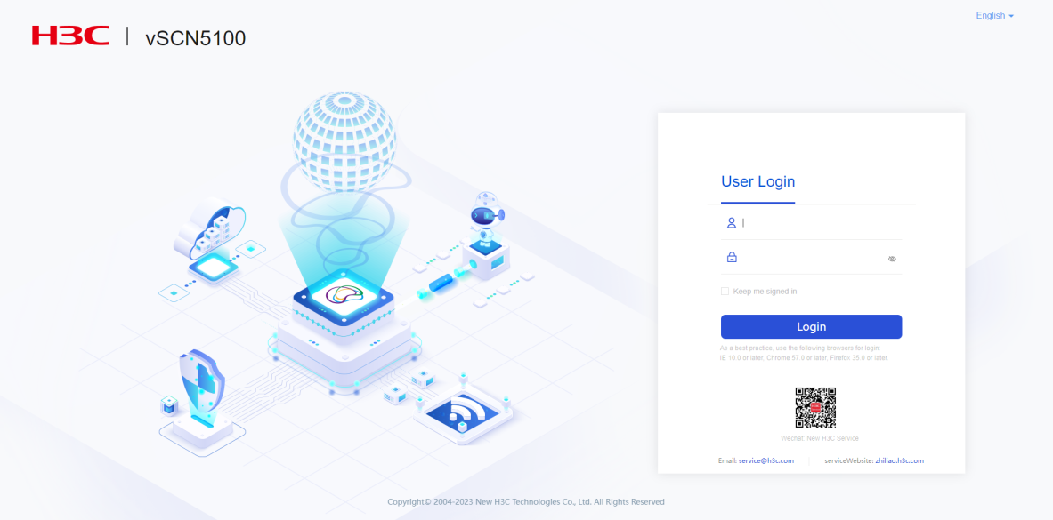
a. As shown in Figure 3, enter the factory default username and password, and then log in to the system.
Figure 3 Entering login information
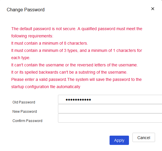
b. As shown in Figure 4, enter the new password on the password change page that opens, and then click OK to change the password.
Figure 4 Changing the password
c. On the login page, enter the username and the new password, and then log in to the system.
Logging out of the web management interface
To ensure the security of the vSCN5100, promptly exit the web interface after completing operations.
Select admin > Log Out in the top right corner of the page to exit the web.
When you exit the Web, the system will not automatically save the current configuration. Therefore, save the device configuration before exiting the Web. For more information about saving configurations, see sections "vSCN feature configuration restrictions and guidelines."
Closing the browser directly will not log you out of the Web.
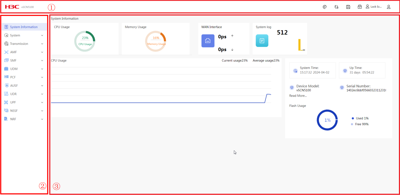
Web page layout
|
(2) Navigation pane |
|
|
(3) Content pane |
|
|
|
NOTE: Web pages might vary between versions. See the actual product web page for specifics. |
As shown in Figure 5, the Webpage has the following functional areas:
· Banner and auxiliary area: Displays the company logo and login user information, with functions such as language switchover, screen lock, password change, configuration saving, and logout.
· Navigation pane: Provides the Web menu for device functions in a tree structure. You can easily select function menus in the navigation pane. The content pane displays the selection result.
· Content pane: Allows users to perform configuration tasks, and view information and the operation result.
vSCN feature configuration restrictions and guidelines
· After configuring the device, save the current configuration promptly to prevent configuration loss as a best practice. To save the configuration:
¡ Click
the ![]() icon at the upper right corner of the banner and auxiliary area,
and then click Yes in the confirmation dialog box that opens.
icon at the upper right corner of the banner and auxiliary area,
and then click Yes in the confirmation dialog box that opens.
¡ Navigate to System Management> Configuration Management, click the Back Up/Restore Configuration tab, and then click Save Running Configuration. In the dialog box that opens, save the running configuration to the next startup configuration file, and then click OK.
· The parameters not listed in the following vSCN configuration process indicate that these parameters can be configured with predefined data or do not require configuration during this service activation.
· When the NMS connects to the vSCN through SFTP or Restful, specify the username and password on the vSCN. The default username and password for vSCN are shown in Table 13.
Table 13 Default username and password for vSCN
|
Username |
Password |
|
emsadmin |
cg5*@cNc3h |
Configuring the vSCN basic services
Configuring the human-machine command interaction feature
Overview
The human-machine command is the command line for managing and maintaining devices.
Use commands to configure certain functions of the current vSCN5100. This section explains how to log in to the device's human-machine command interaction page through the device's web page, that is, how to access the command line interface (CLI) through the device's web page. Log in to the human-machine command interaction page using the Secure Shell (SSH) protocol. In this scenario, the device acts as an SSH server and the device's web page serves as the SSH client.
Procedures
1. Select Systems > Management Protocols to access the Management Protocols page.
2. Click the SSH tab to access the SSH page.
3. Enable the Stelnet service on the SSH page.
|
|
NOTE: By default, the Stelnet service is enabled. |
4. Click the WebSSH tab to access the WebSSH page.
5. Enable the WebSSH service on the WebSSH page.
6. Select Systems > Command Line to access the Command Line page.
7. Enter the username and password for logging into vSCN5100 on the pop-up page, click Log In to access the human-machine command interaction page.
Setting the host name for each network element
Overview
The host names of the AMF, SMF, UDM, PCF, AUSF, and UDR network elements are used for PDU session establishment and element discovery. The host names must be configured.
Procedures
1. Access the human-machine command page. For more information, see "Configuring the human-machine command interaction feature."
2. Enter system view.
<H3C> system-view
System View: return to User View with Ctrl+Z.
3. Configure the host names for the AMF, SMF, UDM, PCF, AUSF, and UDR network elements. When configuring the first element's host name, enter 'y' as prompted by the interactive information. To avoid frequently restarting the device, configure the host names for all network elements before saving the configuration and restarting the device. Otherwise, the host names will not take effect.
[H3C] amf hostname 460 011 amf
[H3C] smf hostname 460 011 smf
[H3C] udm hostname 460 011 udm
[H3C] pcf hostname 460 011 pcf
[H3C] ausf hostname 460 011 ausf
[H3C] udr hostname 460 011 udr
|
Type |
Parameter |
Sample value |
|
AMF Host Name |
MCC |
460 |
|
MNC |
011 |
|
|
NFName |
amf |
|
|
SMF Host Name |
MCC |
460 |
|
MNC |
011 |
|
|
NFName |
smf |
|
|
UDM Host Name |
MCC |
460 |
|
MNC |
011 |
|
|
NFName |
udm |
|
|
PCF Host Name |
MCC |
460 |
|
MNC |
011 |
|
|
NFName |
pcf |
|
|
AUSF Host Name |
MCC |
460 |
|
MNC |
011 |
|
|
NFName |
ausf |
|
|
UDR Host Name |
MCC |
460 |
|
MNC |
011 |
|
|
NFName |
udr |
4. Save the configuration and reboot the device.
<H3C> quit
<H3C> save
The current configuration will be written to the device. Are you sure? [Y/N]:y
Please input the file name(*.cfg)[flash:/startup.cfg]
(To leave the existing filename unchanged, press the enter key):
flash:/startup.cfg exists, overwrite? [Y/N]:y
Validating file. Please wait...
Saved the current configuration to mainboard device successfully.
<H3C> reboot
Start to check configuration with next startup configuration file, please wait..
.......DONE!
This command will reboot the device. Continue? [Y/N]:y
Now rebooting, please wait...
Configuring IP addresses for interfaces
1. From the navigation pane, select Transmission > IPv4 to access the IPv4 page.
2. Click the IPv4 Addresses tab to access the IPv4 page.
3. Assign an IP address to the N2 interface:
Move the cursor to the row with the XGE1/0/0 interface and click the edit icon that appears on the right of XGE1/0/0 to access the IP settings modification page.
Configure the parameters as described in the following table and click Apply to complete the IP address configuration.
|
Parameter |
Sample value |
Remarks |
|
IP address |
Mannual assignment |
Specify an IP address to configure it statically. |
|
Secondary IP address/mask |
10.20.2.10/24 |
IP address and mask for the AMF's N2 interface |
|
|
NOTE: · In this example, the XGE1/0/0 interface is a 10-Gigabit interface created during the installation of vSCN. The interface type displayed on the Web is determined by the configuration set during the installation of vSCN. Refer to the actual interface type displayed on the Web for specifics. · In this example, since the XGE1/0/0 interface was already configured with an IP address for Web management access during the vSCN installation, the IP address for the N2 interface being configured must be set as the secondary IP address of the interface. · After entering the N2 interface IP address, click the |
4. Configure the IP addresses for the N3 and N6 interfaces.
Click the edit icon next to XGE1/0/1 on the page to access the IP settings modification page.
Configure the parameters based on the following table and click Apply to complete the IP address configuration.
|
Parameter |
Sample values |
Remarks |
|
IP address |
Mannual assignment |
Specify an IP address to indicate it has been configured manually with a static setting. |
|
IP address/mask |
10.20.3.10/24 |
IP address and mask for the UPF's N3 interface |
|
Secondary IP address/mask |
10.20.4.10/24 |
IP address and mask for the UPF's N6 interface |
|
|
NOTE: · In this example, the XGE1/0/1 interface is a 10-gigabit interface created during the vSCN installation. The interface type displayed on the Web is determined by the configuration set during the vSCN installation. For accuracy, refer to the actual interface type displayed on the Web. · In this example, the N3 interface IP address serves as the primary IP address for the XGE1/0/1 interface, and the N6 interface IP address is the secondary IP address for the XGE1/0/1 interface. · After configuring the N3 interface IP address, set the secondary
IP address for the N6 interface. Then click the |
Configuring static routes
1. Select Transmission > Routing, and then click the ![]() icon to the right of the IPv4 static routing on the static routing page to enter the IPv4 static routing page.
icon to the right of the IPv4 static routing on the static routing page to enter the IPv4 static routing page.
2. Configure a static route for the N2 interface.
Click Add on the IPv4 static routing page.
To add a static route for the core network N2 interface to the base station N2 on the IPv4 static route page, configure the parameters as described in the following table. Click Apply to complete the static route configuration.
|
Parameter |
Sample value |
|
VRF |
Public network |
|
Destination IP address |
199.23.1.2 |
|
Mask Length |
24 |
|
Next hop IP address |
10.20.2.1 |
3. Configure a static route for the N3 interface.
Click Add on the IPv4 static routing page again to enter the page for adding an IPv4 static route.
To add a static route from the core network N3 interface to the base station N3 on the IPv4 static route page, configure the parameters as described in the following table and click Apply to complete the static route configuration.
|
Parameter |
Sample value |
|
VRF |
Public network |
|
Destination IP address |
199.23.2.2 |
|
Mask Length |
24 |
|
Next hop IP address |
10.20.3.1 |
4. Configure the default route for the N6 interface.
Click Add on the IPv4 static routing page again.
To add a default route from the core network N6 interface to DN on the IPv4 static route page, configure the parameters as described in the following table. Click Apply to complete the static route configuration.
|
Parameter |
Sample Value |
|
VRF |
Public network |
|
Destination IP address |
0.0.0.0 |
|
Mask Length |
0 |
|
Next hop IP address. |
10.20.4.1 |
|
|
NOTE: The default route is used when no matching route entry is found. |
Licensing
1. Select System > License > License Configuration to access the license configuration page.
2. On the license configuration page, set the parameter as described in the following table.
|
Parameter |
Sample value |
|
5GC State |
Enable |
|
UDR Subscribers Number |
100 |
|
AMF Online Users Number |
100 |
|
Base Stations Number |
10 |
|
Sessions Number |
100 |
|
Bandwidth Number |
5 |
|
PCF Vonr Services Number |
100 (Optional) voice services |
|
IWF feature |
Enable |
|
Online IMS users |
100 (optional) voice services |
3. Click OK.
Configuring AMF
Configuring GUAMI
1. Select AMF > Network Planning to access the network planning page.
2. Click the GUAMI tab to access the GUAMI page.
3. On the GUAMI page, configure the parameters as described in the following table.
|
Parameter |
Sample value |
|
MCC |
460 |
|
MNC |
11 |
|
Region ID |
255 |
|
Set ID |
1023 |
|
Pointer |
63 |
4. Click OK.
Configuring the service PLMN
1. Select AMF > Network Planning to access the network planning page.
2. Click the Service PLMN tab to access the service PLMN page.
3. On the Service PLMNs tab, click Add. The Add Service PLMNs page opens.
4. Configure the parameters as needed on the page.
|
Parameter |
Sample Value |
|
MCC |
460 |
|
MNC |
11 |
|
S-NSSAIs |
SST: 1 SD: 010203 |
|
|
NOTE: · You must click the · To edit an added S-NSSAI entry, click the |
5. Click OK.
Configuring the TAI list
1. Select AMF > Network Planning to access the Network Planning page.
2. Click the TAI List tab to access the TAI List page.
3. On the TAIs tab, click Add. The Add TAI page opens.
4. On the Add TAI page, configure the parameters as described in the following table.
|
Parameter |
Sample value |
|
TAC |
1 |
|
MCC |
460 |
|
MNC |
11 |
|
TAI List Index |
1 |
|
RRC_Inactive Support |
No |
|
Supported S-NSSAIs |
SST: 1 SD: 010203 |
5. Click OK.
Configuring the default DNN
1. Select AMF > Network Planning to access the network planning page.
2. Click the Default DNN tab to access the Default DNN page.
3. On the default DNN page, configure the parameters as described in the following table.
|
Parameter |
Sample value |
|
Default DNN |
default |
4. Click OK.
Configuring the local IP address for the AMF N2 interface
1. Select AMF > N2 Interface to access the N2 Interface page.
2. On the page, click Add. The Add NGAP IP Addresses page opens.
3. On the Add IP Address page, configure the parameters as described in the following table.
|
Parameter |
Sample value |
|
IP version |
IPv4 |
|
Primary IP Address |
10.20.2.10 |
4. Click OK.
Configuring SMF
Configuring the UE IP address pool
1. Select SMF > UE IP Pools to access the UE IP Pools page.
2. Click the UE IP Pools tab to access the UE IP Pools page.
3. Click Add to open the Add UE IP Pool page.
4. On the Add UE IP Pool page, configure the parameters as described in the following table.
|
Parameter |
Sample value |
|
UE IPv4 Pool Name |
ippool |
|
IP Version |
IPv4 |
|
Address Range |
· Index: 1 · Start IP: 60.60.60.1 · End IP: 60.60.60.30 |
|
|
NOTE: After entering the relevant parameters
for the IP address range, click the |
5. Click OK.
Configuring DNN
1. Select SMF > Slices and DNNs to access the Slices and DNNs page.
2. Click the DNNs tab on the Slices and DNNs page to access the DNNs page.
3. Click Add to open the add DNNs page.
4. Configure the parameters as described in the following table.
|
Parameter |
Sample value |
|
DNN |
default |
|
Session Rule Name |
default |
|
Default PDU Session Anchor Type |
· Node · default |
|
UE IPv4 Pool Name |
ippool |
|
|
NOTE: You must configure the SMF's UE IPv4 pool before setting the UE IPv4 pool name in the DNNs. |
5. Click OK.
Configuring UPF
Configuring the GTPU IP address
1. Select UPF > User Plane Interfaces to access the User Plane Interfaces page.
2. Click the GTPU IP Addresses tab to access the GTPU IP Addresses page.
3. Configure the parameters as described in the following table.
|
Parameter |
Example value |
|
IPv4 address |
10.20.3.10 |
4. Click OK.
Configuring UDR
Configuring the OP ID
1. Select UDR > Authentication Global Data to access the Authentication Global Data page.
2. Click the OP tab to access the OPID page.
3. Click Add to open the Add OPID page.
4. Configure the parameters as described in the following table.
|
Parameter |
Sample value |
|
OP ID |
1 |
|
OP Value |
c9e8763286b5b9ffbdf56e1297d0887b |
5. Click OK.
Setting the AMF serial number
1. Select UDR > Authentication Global Data to access the Authentication Global Data page.
2. Click the AMF tab to access the AMFSNO page.
3. Click Add to open the Add AMFSNO page.
4. Configure the parameters as described in the following table.
|
Parameter |
Sample value |
|
AMF SNO |
1 |
|
AMF Value |
8000 |
5. Click OK.
Configuring a 5GS QoS template
1. Select UDR > Template to access the Template page.
2. Click the 5GS QoS Template tab to access the 5GS QoS Template page.
3. Click Add to open the page for adding a 5GS QoS template.
4. Configure the parameters as described in the following table.
|
Parameter |
Sample Value |
|
Template ID. |
1 |
|
5QI |
7 |
|
ARP Priority Level |
9 |
|
ARP PreemptCap |
On |
|
ARP PreemptVuln |
On |
5. Click OK.
Configuring the DNN QoS template
1. Select UDR > Template to access the Template page.
2. Click the DNN QoS Template tab to access the DNN QoS Template page.
3. Click Add on the DNN QoS template page to open the add DNN QoS Template page.
4. Configure the parameters as described in the following table.
|
Parameter |
Sample value |
|
Template ID. |
1 |
|
Default PDU Session Type |
IPV4V6 |
|
Default SCC Mode |
SCC Mode 1 |
|
5GS QoS Template ID |
1 |
|
Uplink DNN AMBR |
1000000 |
|
Uplink DNN AMBR Unit |
Kbps |
|
Downlink DNN AMBR |
1000000 |
|
Downlink DNN AMBR Unit |
Kbps |
5. Click OK.
Configuring the 5GS user template
1. Select UDR > Template to access the Template page.
2. Click the 5GS User Template tab to access the 5GS User Template page.
3. Click Add to open the Add 5GS User Template page.
4. Configure the parameters as described in the following table.
|
Parameter |
Example Values |
|
Template ID |
1 |
|
Uplink UE AMBR |
1000000 |
|
Uplink UE AMBR Unit |
Kbps |
|
Downlink UE AMBR |
1000000 |
|
Downlink UE AMBR Unit |
Kbps |
|
Authentication Method |
5G AKA |
|
Access and Mobility S-NSSAIs |
· S-NSSAI: 1-010203 · Default: TRUE |
|
Session Management S-NSSAIs |
· S-NSSAI: 1-010203 · DNN: default · DNN QoS Template ID: 1 · Default: TRUE |
5. Click OK.
Creating a bulk card activation file
1. Create the text file required for bulk card activation and name it ki.txt.
2. In ki.txt, add authentication data for each user on a separate line in the format IMSI KI OP ID, with spaces separating the fields. For example, 460110000000001 5122250214c33e723a5dd523fc145fc0 1 and 460110000000002 5122250214c33e723a5dd523fc145fc0 1.
3. Save the file.
Creating a bulk account opening file
1. Create the text file required for bulk activation and name it subs.txt.
2. In subs.txt, add user subscription data with each user's data on a separate line in the format IMSI ISDN, using spaces to separate different fields. For example, 460110000000001 10001 and 460110000000002 10002.
3. Save the file.
Uploading batch files
1. Select Systems > File Transfer to access the File System page.
2. Click Upload to open the upload file page.
3. Click Select file, select the previously saved ki.txt, click Open, then click Apply to complete the bulk card activation file upload.
4. Click Select file, select the previously saved subs.txt, click Open, then click Apply to complete the bulk account creation file upload.
Activating cards in bulk
1. Select UDR > Batch Operation to access the Batch Operation page.
2. Click the Batch Authentication Data tab to access the Batch Authentication Data page.
3. Configure the parameters as described in the following table.
|
Parameter |
Sample Value |
|
Operation |
BAT_ADD_KI |
|
Batch operation filename |
ki.txt |
|
Algorithm Type |
MILENAGE |
|
AMF SNO |
1 |
4. Click OK to start batch card activation.
5. After the batch card activation, click [UDR/Authentication Data] in the Web navigation bar in sequence to access the Authentication Data page, where you can see that the authentication data from the ki.txt file has been written.
Opening accounts in bulk
1. Select UDR > Batch Operation to access the Batch Operation page.
2. Click the Batch Add Remove Subscription tab to access the Batch Add Remove Subscription page.
3. Configure the parameters as described in the following table.
|
Parameter |
Sample value |
|
Operation |
BAT_ADD_SUB_BY_FILE |
|
Batch File Name |
subs.txt |
|
5GS User Template ID |
1 |
4. Click OK to start batch account creation.
5. After completing bulk account opening, click [UDR/Subscription] in the Web navigation bar to access the Subscription page. Then click the [5GS Subscription Data] tab to view the users specified in the subs.txt file, which have been created with the preset 5GS user template.
Saving the basic service configuration
See "vSCN feature configuration restrictions and guidelines" for methods to save configurations.
(Optional) Configuring the vSCN voice services
Configuring IP addresses for interfaces
1. Select Transmission > IPv4 to access the IPv4 page.
2. Click the IPv4 Address tab to access the IPv4 page.
3. Assign an IP addresses to the Rx interface.
Click the edit icon ![]() next to XGE1/0/1 on the page to access the IP settings modification
page.
next to XGE1/0/1 on the page to access the IP settings modification
page.
Configure the parameters as described in the following table. Click Apply.
Configuring static routes
1. Select Transmission > Routing, and then click the ![]() icon on the right side of the IPv4 static routing page to access the IPv4 static routing page.
icon on the right side of the IPv4 static routing page to access the IPv4 static routing page.
2. Configure a static route from the IWF Rx interface to IMS.
a. Click Add to access the New IPv4 Static Route page.
b. Configure the parameters as described in the following table, and click OK to add a static route from the IWF Rx interface to IMS.
3. Configure a static route from the UPF N6 interface to IMS.
a. Click Add to enter the New IPv4 Static Route page.
b. Configure the parameters as described in the following table and click OK to add a static route for the UPF N6 interface to IMS.
Configuring the voice service features of AMF
1. Select AMF > Service-Based Interfaces to access the Service-Based Interfaces page.
2. Click the Nsmf(N11) Interface Peer Mapping Rules tab to open the Nsmf(N11) Interface Peer Mapping Rules page.
3. Click Add to open the page for adding Nsmf(N11) interface peer mapping rules.
4. Configure the parameters as described in the following table.
|
Parameter |
Sample values |
|
N11 Peer Mapping Name |
ims |
|
Mapping Type |
DNN Type |
|
DNN |
ims |
|
SST |
1 |
|
SD |
010203 |
|
SMF Set Name |
default |
5. Click OK.
Configuring the voice service features of SMF
Configuring P-CSCF node information
1. Select SMF > P-CSCF NF Info to access the P-CSCFs page.
2. Click Add to open the P-CSCFs page.
3. Configure the parameters as described in the following table.
|
· IPv4 address: 10.30.0.11 · Priority: 1. · Capacity: 1 |
Configuring the UE IP address pool
1. Select SMF > UE IP Pools in the navigation bar on the Web management homepage to access the UE IP Pools page.
2. Click the UE IP Pools tab to open the UE IP Pools page.
3. Click Add to open the Add UE IP Pool page.
4. Configure the parameters as described in the following table.
Configuring DNN
1. Select SMF > Slices and DNNs to access the Slices and DNNs page.
2. Click the DNNs tab on the Slices and DNNs page to access the DNNs page.
3. Click Add to open the Add DNNs page.
4. Configure the parameters as described in the following table.
|
Session Rule Name |
default |
|
N7 Peer Set |
default |
Configuring the voice service features of PCF
Setting up session rules
1. Select PCF > Session Rules to access the Session Rules page.
2. Click Add to open the Add Session Rules page.
3. Configure the parameters as described in the following table.
Configuring session policy
1. Select PCF > Session Policies, then click the Session Policies tab to access the Session Policies page.
2. Click Add to open the Add SM Policy page.
3. Configure the parameters as described in the following table.
Configuring the service policy
1. Select PCF > Session Policies, then click the Service Policies tab to access the Service Policies page.
2. Click Add to open the Add Service page.
3. Configure the parameters as described in the following table.
Configuring policy data binding
1. Select PCF > Policy Data to access the Policy Data Bindings page.
2. Add policy data binding for UE 1.
a. Click Add on the Policy Data Bindings page to open the Add Policy Data Binding page.
b. Configure the parameters as described in the following table.
3. Add policy data binding for UE 2.
a. Click Add on the Policy Data Bindings page to open the Add Policy Data Binding page.
b. Configure the parameter as described in the following table.
Configuring the voice service features of UDR
1. Select UDR > 5GS Subscription Data to access the 5GS Subscription Data page.
2. Click the Session Management Data tab to access the Session Management Data page.
a. Click "Add" to open the Add Session Management Data page.
b. On the Add Session Management Data page, configure the parameters to match the values in the corresponding examples.
|
DNN |
ims |
|
DNN QoS Template ID |
1 |
|
Default |
False |
a. Click <Add> to open the Add Session Management Data page.
b. Configure the parameters as described in the following table.
|
Parameter |
Sample value |
|
UEID Version |
IMSI |
|
UEID |
460110000000002 |
|
S-NSSAI |
1- 010203 |
|
DNN |
ims |
|
DNN QoS Template ID |
1 |
|
Default DNN |
False |
c. Click OK.
Configuring the voice service features of external IMS
Configuring the voice service features of IWF
Configuring the diameter link
1. Enter the human-machine command page; for specific methods, see "Configuring the human-machine command interaction feature."
2. Enter system view.
<H3C> system-view
System View: return to User View with Ctrl+Z.
3. Configure IWF Diameter information.
[H3C] iwf diameter application rx ipv4 10.20.5.10 local-host iwf.mnc011.mcc460.3gppnetwork.org local-realm mnc011.mcc460.3gppnetwork.org
|
Parameter |
Sample value |
|
IPv4 Address |
10.20.5.10 |
|
Local-host |
iwf.mnc011.mcc460.3gppnetwork.org |
|
local-realm |
mnc011.mcc460.3gppnetwork.org |
|
|
NOTE: Configure the Diameter information here based on laboratory planning data (using an IPv4 address as an example; vSCN also supports IPv6 addresses for IMS integration). Adjust according to the actual situation. If necessary, configure the relevant routes to ensure route accessibility between IWF and IMS. |
Configuring the voice service features of proprietary vIMS integration
The following configuration applies only to scenarios where vIMS and vSCN are co-deployed. For standalone vIMS deployment, refer to other relevant documentation.
Configuring static routes
1. Select Transmission >
Routing
Management, and then click the ![]() icon
on the right side of the IPv4 static routing page to access the IPv4 Static Routing page.
icon
on the right side of the IPv4 static routing page to access the IPv4 Static Routing page.
2. Click Add on the IPv4 Static Routing page to enter the Add IPv4 Static Route page.
3. Configure the parameters as described in the following table and click Apply to add a static route for IMS to the XGE1/0/0 interface.
|
Parameter |
Sample value |
|
VRF |
Public network |
|
Destination IP |
70.70.70.0 |
|
Mask Length |
24 |
|
Output interface |
XGE1/0/0 |
Configuring the primary IP address for the interface
1. Click on Transmission > IPv4 Management] in the navigation bar on the Web Management homepage to access the IPv4 Management page.
2. In the IPv4 Management page, select the XGE1/0/0 interface to enter the Edit IP page.
3. Configure the parameters as described in the following table and click Apply.
|
Parameter |
Sample value |
|
IP address |
Manual assignment |
|
IP address/mask |
10.30.0.11/24 |
|
|
NOTE: Configure the IPv4 address here as the planned IMS address, which matches the P-CSCF address set in the SMF. |
Configuring IMS
Configuring the service PLMN
1. Click on IMS > IMS Network Management in the navigation bar on the Web Mgmt homepage in sequence to access the IMS Network Management page.
2. Configure the parameter as described in the following table.
|
Parameter |
Example values |
|
MCC |
460 |
|
MNC |
011 |
3. Click OK.
Configuring the SBI IP address
1. Select IMS > SBI IP Addresses in the navigation bar on the Web Mgmt homepage in succession to access the SBI IP Addresses page.
2. Configure the local IP address.
Click the Local IP Addresses tab to access the Local IP Addresses page.
Set the parameter as described in the following table, click OK.
|
Parameter |
Example value |
|
Local IPv4 Address |
127.0.0.1 |
|
Local IPv4 Address port |
29564 |
3. Configure the IMS-HSS IP address.
Click the HSS IP addresses tab to access the HSS IP addresses page.
Set the parameters as described in the following table and click OK to complete the configuration.
|
Parameter |
Sample value |
|
IMS-HSS IPv4 Address |
127.0.0.1 |
|
IMS-HSS IPv4 Port |
29562 |
4. Configure the PCF IP address.
Click the PCF IP Addresses tab to access the PCF IP Addresses page.
Set the parameter to the value shown in the example and click OK to complete the configuration.
|
Parameter |
Example value |
|
PCF IPv4 Address |
127.0.0.1 |
|
PCF IPv4 Port |
29507 |
Configuring VoNR registration
1. Select IMS > VoNR Registration in the navigation bar on the Web Mgmt homepage in sequence to access the VoNR Registration page.
2. Select the "On" check box.
3. Adjust the "Registration Valid For" as needed; if there are no specific requirements, keep the default.
4. Check the "On" check box.
5. Adjust the "Subscribe to Registration Info" as needed; if there are no special requirements, keep the default setting.
6. Click OK.
Configuring IMS server-related features
1. Access the human-machine command page; for specific methods, see "Configuring the human-machine command interaction feature."
2. Enter system view.
<H3C> system-view
System View: return to User View with Ctrl+Z.
3. Configure IMS interface binding.
# Enter the voice settings view.
[H3C]voice-setup
# Enter the SIP settings view.
[H3C-voice]sip
# Bind the SIP data plane interface.
[H3C-voice-sip]bind media source-interface Ten-GigabitEthernet 1/0/0
# Bind the SIP Ctl plane interface.
[H3C-voice-sip]bind control source-interface Ten-GigabitEthernet 1/0/0
|
|
NOTE: Configure the primary address on the Ten-GigabitEthernet 1/0/0 interface here to be the IMS address from the example value (10.30.0.11). |
Configuring IMS-HSS
Configuring the subscriber template
1. Click on IMS-HSS > Subscriber Management in the navigation bar on the Web Mgmt homepage to access the Subscriber Management page.
2. Click the Subscriber Template tab to access the Subscriber Template page.
3. Click Add to open the Add Subscriber Template page.
4. Configure the parameter as described in the following table.
|
Parameter |
Sample value |
|
Subscription Template Name |
template |
|
K |
Maintain the default value. |
|
OP |
Maintain the default value. |
|
AMF |
Maintain the default value. |
|
MCC |
460 |
|
MNC |
11 |
Configuring batch contracted user information
1. Select IMS-HSS > Subscription Management in the navigation bar on the Web management homepage to access the Subscription Management page.
2. Click the Bulk Actions on Subscribers tab to access the Bulk Actions on Subscribers page.
3. Add bulk new subscriber information.
Configure the parameters as described in the following table.
|
Parameter |
Sample value |
|
Operation |
Add |
|
Subscriber Template Name |
template |
|
Start SUPI |
460110000000001 |
|
Start Phone Number |
136888880001 |
|
Subscribers |
10 |
After configuring the parameters, click OK.
4. Batch modify contracted user information.
Configure the parameters as described in the following table.
|
Parameter |
Sample value |
|
Operation |
Edit |
|
Subscriber Template Name |
template |
|
Start SUPI |
460110000000001 |
|
Start Phone Number |
136888880001 |
|
Subscribers |
10 |
After configuring the parameters, click OK.
5. Use this feature to bulk delete contracted user information.
Configure the parameters as described in the following table.
|
Parameter |
Sample value |
|
Operation |
Delete |
|
Start SUPI |
460110000000001 |
|
Subscribers |
10 |
a. After configuring the parameters, click OK.
Configuring the service-oriented interface
1. Select IMS-HSS > SBI IP Management in the navigation bar on the Web management homepage to access the Local IP Address page.
2. Set the parameters as described in the following table and click OK to complete the configuration.
|
Parameter |
Example values |
|
Local IPv4 Address |
127.0.0.1 |
|
Local IPv4 Port |
29562 |
Saving voice service configuration
For the method to save configurations, see "vSCN feature configuration restrictions and guidelines."
Verifying the services
Verifying basic services
Before business qualification, complete the following preparations:
· Validate that the gNodeB state is normal and has successfully connected to the vSCN.
· Validate that the UE state is normal.
· The vSCN has obtained a License for local or remote authorization.
· The vSCN has successfully completed its feature configuration.
· Open the UE network to connect the UE to the gNodeB and access the DN by establishing a PDU session.
|
|
NOTE: This manual qualifies one of the account holders as the contracted user. |
Viewing user contract information
1. Select UDR > Subscription in the navigation bar on the Web Management homepage in sequence to access the Subscription page.
2. Click the "5GS Subscription Data" tab on the User Management page to access the 5GS Subscription Data page.
3. View brief information about contracted users.
On the 5GS Subscription Data page, you can view brief information about subscribed users.
4. View the detailed information of the contracted users.
a. Move the mouse over the contract information and click Edit that appears on the right to open the 5GS Subscription Data page.
b. View the detailed information of the contracted users.
Viewing UDM UE context information
1. Select UDM > UE contexts in the navigation bar on the Web Management homepage in sequence to access the UE contexts page.
2. View brief information about contracted users.
On the UE contexts page, you can view brief information about the subscribed users.
Check if the registration state is RM-REGISTERED. If it is, the user has successfully registered with vSCN; if not, the user has not registered with vSCN.
Viewing AMF UE context information
1. Select AMF > UE Contexts > 5G UE Contexts in the navigation bar on the Web Mgmt homepage in succession to access the 5G UE Contexts page.
2. View a summary of the AMF 5G user context information.
On the 5G UE Contexts page, you can view a summary of the AMF 5G user context information.
3. For more information about AMF 5G user context details, view the specific information.
Move the mouse over the AMF 5G user context information and click Edit that appears on the right to open the AMF 5G User Context Details page.
For more information about AMF 5G user context details, view the detailed information.
- Check whether the AMF 5G user context information matches the configured profile.
- Check if the user's RM state (i.e., registration state) is RM-REGISTERED. If it is, the user is successfully registered with vSCN; if not, the user is not registered with vSCN.
- Check if the user's CM state (that is, connection state) is CM-CONNECTED. If it is, it indicates that a normal connection has been established with the vSCN; otherwise, there is no connection between the user and the vSCN.
Viewing SMF UE context information
1. Click on SMF > UE Contexts in the navigation bar of the Web Mgmt homepage, to access the UE Contexts page.
2. View a summary of the SMF UE context information.
On the UE Contexts page, you can view a summary of the SMF UE context information.
3. For more information about the SMF UE context, view the detailed information.
Move the mouse over the SMF UE context information and click Edit that appears on the right to open the UE Contexts page.
For more information about the SMF UE context, view the detailed information.
- Check whether the SMF UE context information matches the configured information.
- Check if the PDU session state is ACTIVATED. If it is, the user session state is normal; if not, the user has not activated the session.
Viewing user sessions
1. Select UPF > UE Contexts to access the UE Contexts page.
2. Click the UE Session Information tab to access the UE Session Information page, where you can view brief details of the session.
3. For more information about the session, view its details.
a. Move the mouse over the session information and click Edit that appears on the right to open the UE Sessions page.
b. View the detailed PFCP session information for online UEs.
If the query above confirms that the user's contract state, AMF UE contexts, SMF UE contexts, and user session information are all normal, and the user can successfully access the internet, then the core network service activation is successful.
(Optional) Verifying voice services
After successfully interfacing with IMS, UE 1 and UE 2 can make normal voice and video frequency (VF) calls.
