- Table of Contents
- Related Documents
-
| Title | Size | Download |
|---|---|---|
| 01-Text | 16.29 MB |
Contents
Examining the installation site
Installation tools and accessories
Attaching slide rails to the rack
Installing an MPU for an M9000-X06/M9000-AI-X06 gateway
Installing an MPU for an M9000-X10/M9000-AI-X10 gateway
Installing switching fabric modules
Installing interface modules or firewall modules
Installing interface switch modules
7 Installing cable management brackets
Installing transceiver modules and fiber cables
1 Preparing for installation
This document describes the installation procedure for H3C SecPath M9000-X multiservice security gateway series and H3C SecPath M9000-AI-X multiservice security gateway series.
Table1-1 H3C SecPath M9000-X and M9000-AI-X multiservice security gateway series models
|
Gateway series |
Model |
|
M9000-X |
M9000-X06 |
|
M9000-X10 |
|
|
M9000-AI-X |
M9000-AI-X06 |
|
M9000-AI-X10 |
ESD prevention
To prevent electronic components from electrostatic discharge (ESD) damage, wear an ESD wrist strap and insert it into the ESD socket on the chassis. Make sure the ESD wrist strap makes good skin contact and is reliably grounded before you service the device or its components.
|
|
NOTE: The device has an ESD socket on both the front and rear panels. |
Examining the installation site
Make sure the installation site meets the cooling and space requirements.
Space
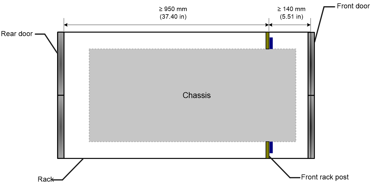
For easy installation and maintenance, make sure the rack has enough space (in height and depth) to accommodate the device. To install the device in an enclosed rack, make sure the rack meets the following requirements:
· Depth—A minimum of 1100 mm (43.31 in) (recommended).
· Distance from the front rack posts to the front door—A minimum of 140 mm (5.51 in).
· Distance from the front rack posts to the rear door—A minimum of 950 mm (37.40 in).
Figure1-1 Device dimension and rack requirements (top view)
|
|
IMPORTANT: · To use an enclosed rack to accommodate the device, make sure you can access the rack from both the front and rear doors. · For easy maintenance, reserve a minimum clearance of 1200 mm (47.24 in) between the device and walls or other devices. |
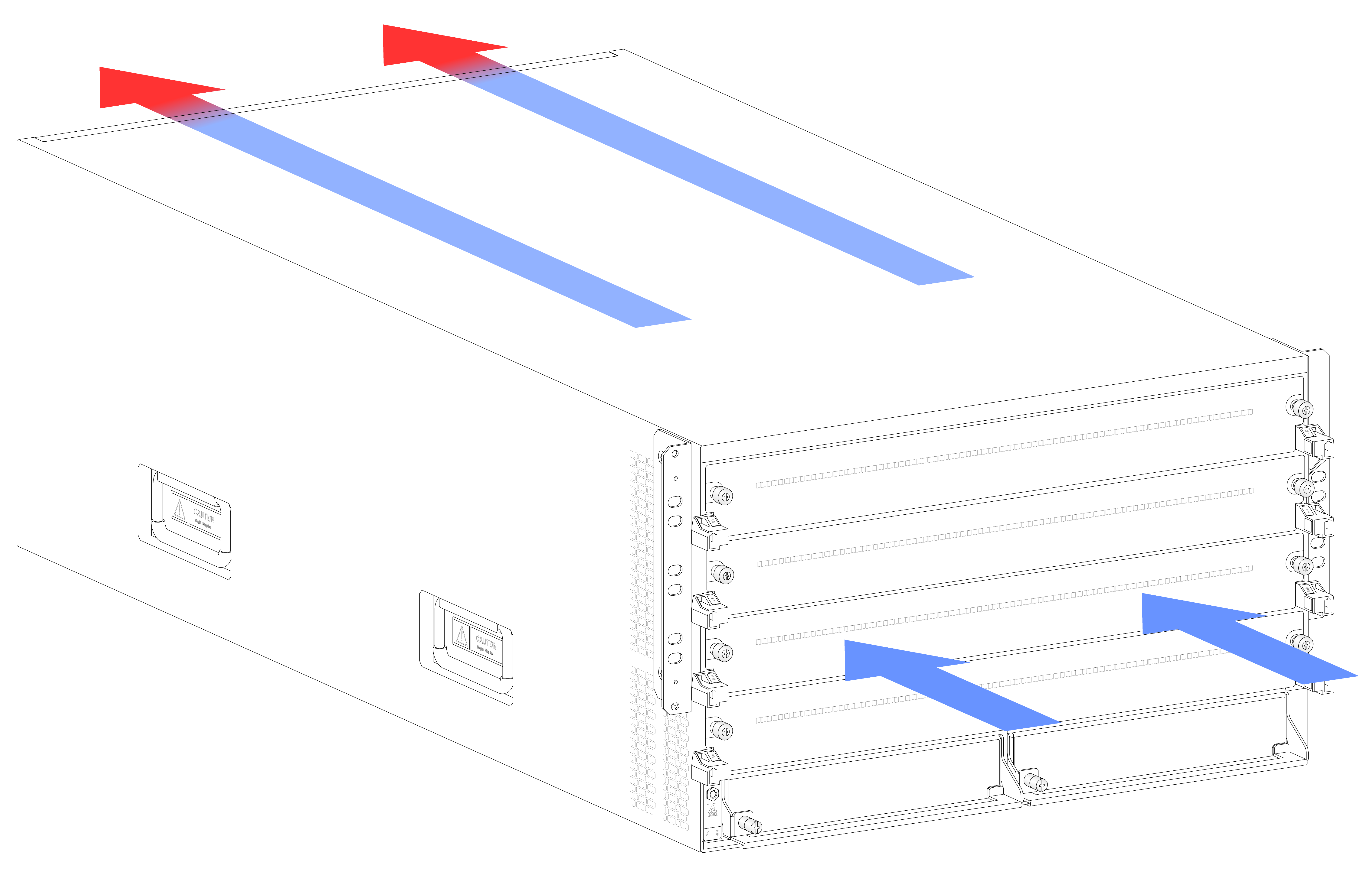
Cooling
The device uses front to rear airflow for heat dissipation. Plan the installation site for adequate ventilation. Leave a minimum clearance of 300 mm (11.81 in) around the inlet and outlet air vents.
Figure1-2 Airflow through the chassis (M9000-X06 gateway)
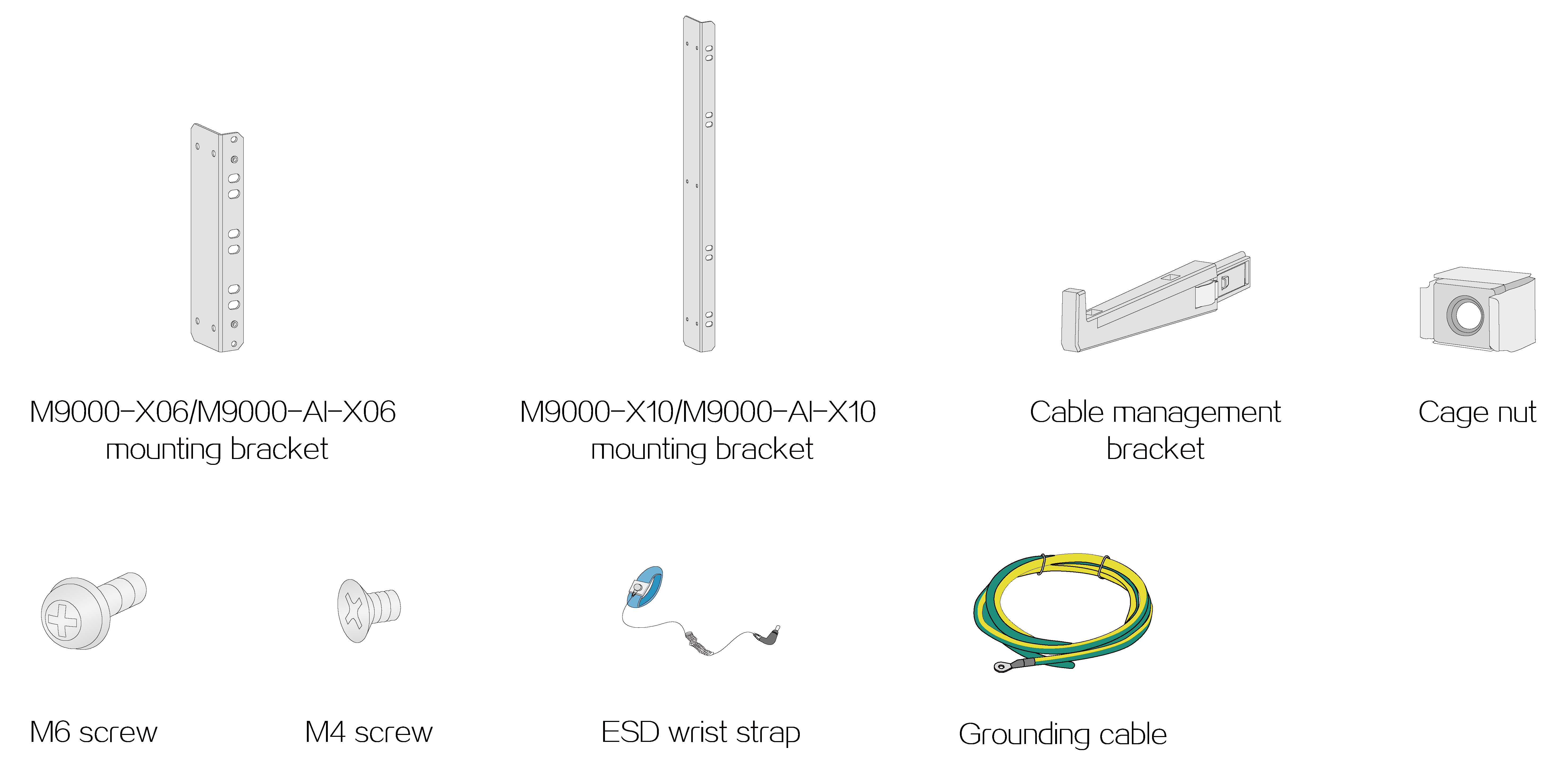
Installation tools and accessories
No installation tools are provided with the device. Prepare them yourself as required.
Figure1-3 Installation tools

Figure1-4 Installation accessories
2 Installing the device
Rack-mounting the device
|
|
CAUTION: The device is heavy. For stability, install it at a lowest possible position. |
Attaching slide rails to the rack
Attach the required slide rails to the rack before you mount the device in the rack. For more information about attaching slide rails, see the slide rail installation guide.
Make sure the slide rail installation positions are at the same height on the four rack posts.
Table2-1 Applicable slide rails
|
Device model |
Chassis weight |
Max. chassis weight (fully configured) |
Applicable slide rails |
||
|
Slide rail model |
Adjustment range |
Occupied rack space |
|||
|
M9000-X06 |
36 kg (79.37 lb) |
120 kg (264.55 lb) |
LSVM1BSR10 |
630 mm to 900 mm (24.80 in to 35.43 in) |
1 RU |
|
M9000-AI-X06 |
36 kg (79.37 lb) |
120 kg (264.55 lb) |
LSVM1BSR10 |
630 mm to 900 mm (24.80 in to 35.43 in) |
1 RU |
|
M9000-X10 |
47 kg (103.62 lb) |
220 kg (485.01 lb) |
LSXM1BSR |
630 mm to 900 mm (24.80 in to 35.43 in) |
1 RU |
|
LSTM2KSGD0 |
500 to 800 mm (19.69 to 31.50 in) |
2 RU |
|||
|
M9000-AI-X10 |
47 kg (103.62 lb) |
220 kg (485.01 lb) |
LSXM1BSR |
630 mm to 900 mm (24.80 in to 35.43 in) |
1 RU |
|
LSTM2KSGD0 |
500 to 800 mm (19.69 to 31.50 in) |
2 RU |
|||
Mounting the device in a rack
|
|
CAUTION: · When you move the device to a low temperature environment from a high temperature environment, condensation might occur. Before installing the device, please dry the device to prevent the internal components from being damaged because of short circuit. · After you place the device on the slide rails, do not leave go of your hands immediately because this might tip the device, damaging the device or even causing bodily injury. |
To mount the device in a rack:
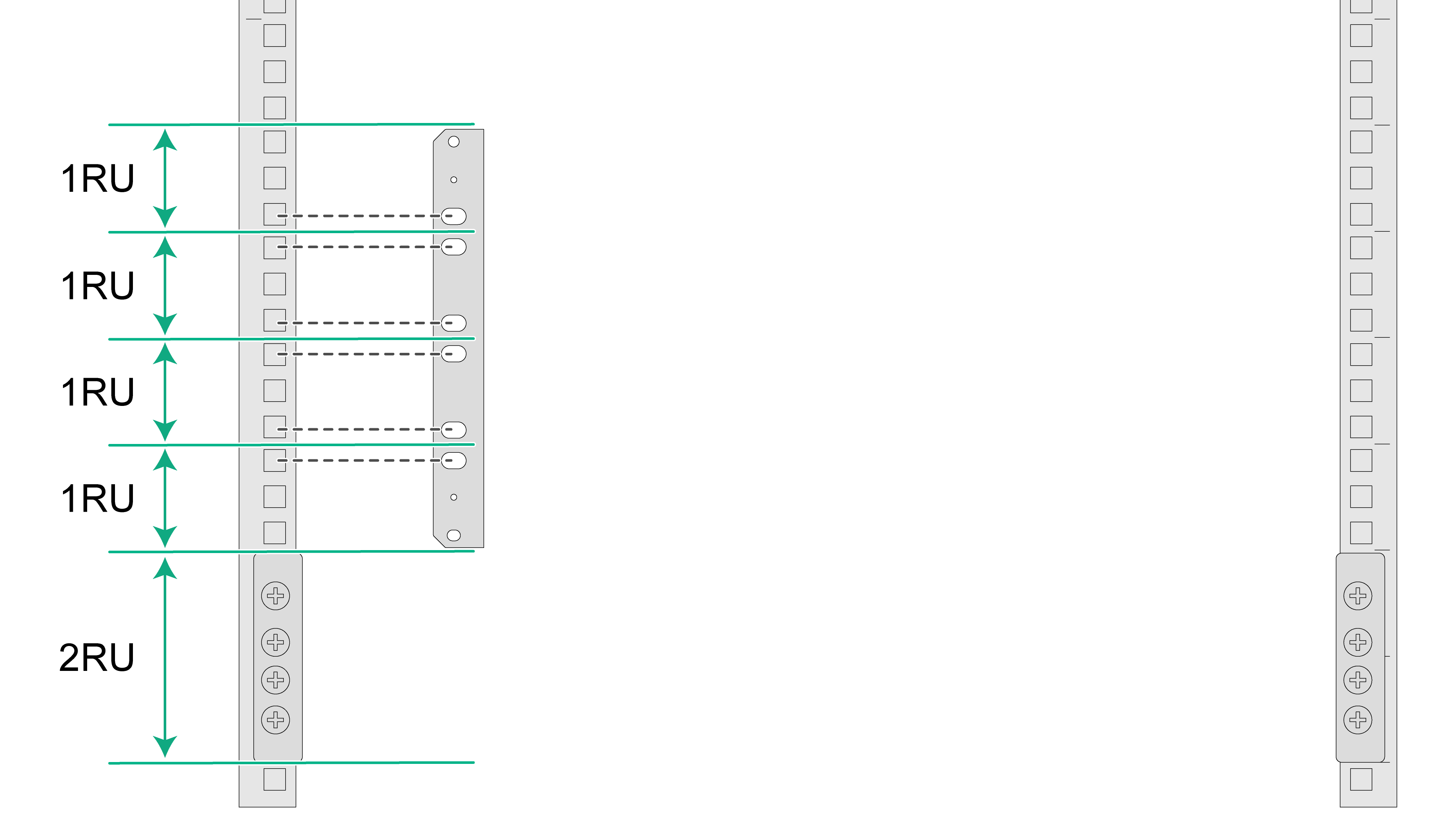
1. Use the mounting brackets to mark the cage nut installation holes on the front rack post.
Figure2-1 Marking cage nut installation holes
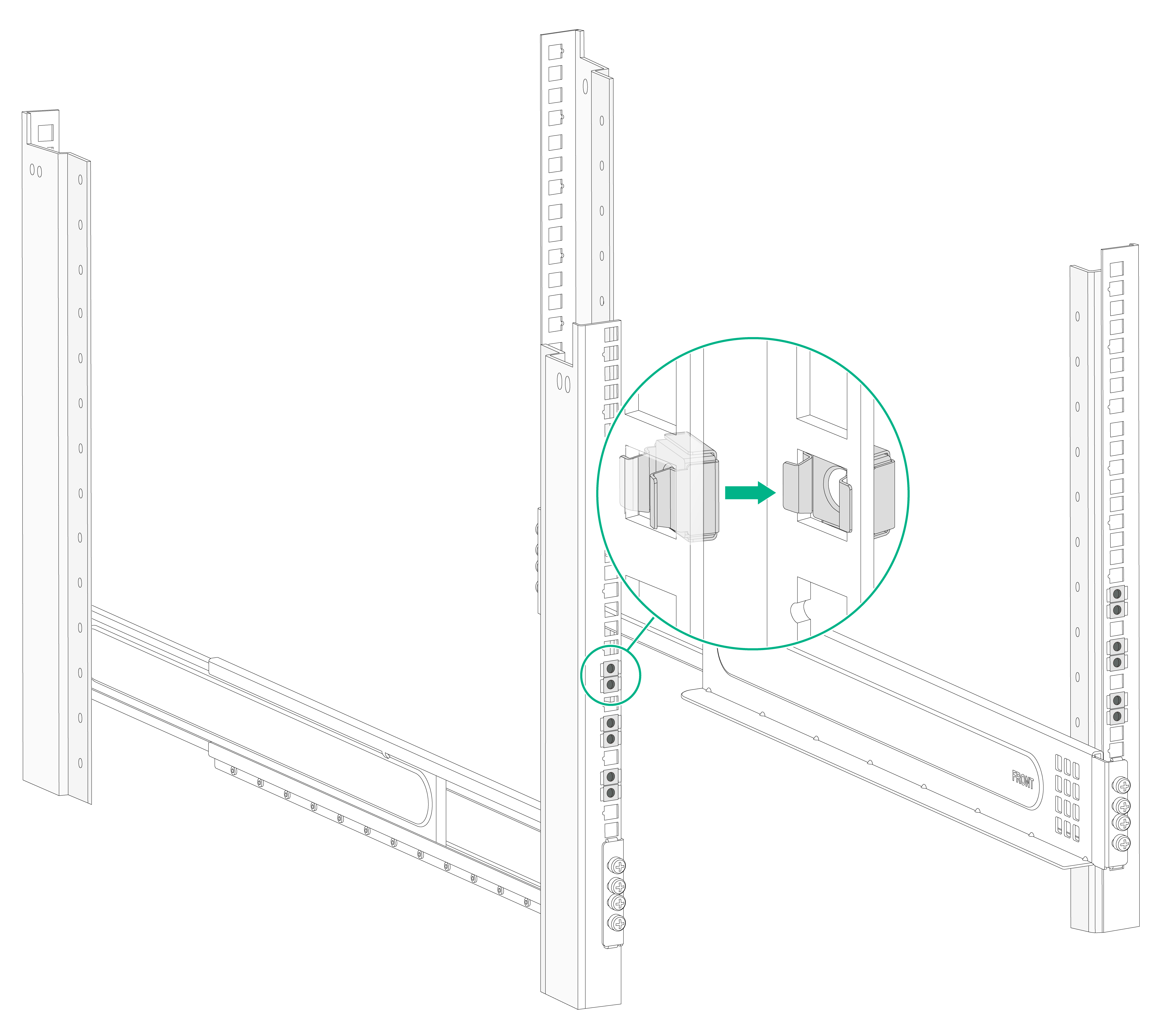
2. Install cage nuts in the marked square holes on the front rack posts.
Figure2-2 Installing the cage nuts
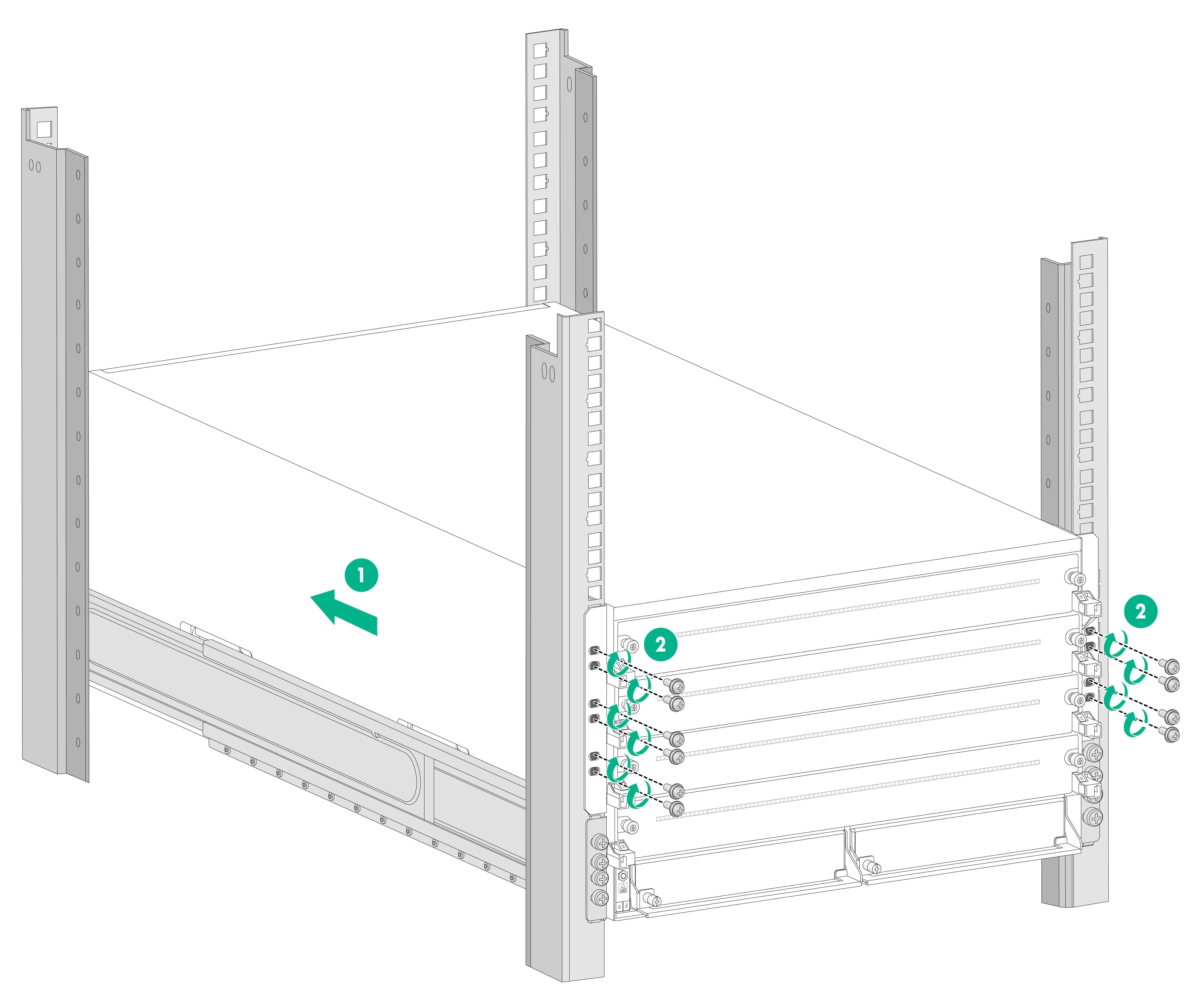
3. Align the rear of the chassis with the front of the rack.
4. Use multiple people to lift the device by holding the chassis handles.
5. Place the device on the slide rails from the front of the rack. Slide the device along the guide rails until the mounting brackets on the device are flush against the front rack posts.
6. Use M6 screws provided with the device to attach the mounting brackets of the device to the rack posts.
Figure2-3 Mounting the device in a rack (M9000-X06 gateway)
Grounding the device
|
|
CAUTION: · Correctly connecting the grounding cable is crucial to lightning protection and EMI protection. Before you install and use the device, make sure the device is reliably grounded. · Connect the grounding cable to the earthing system in the equipment room. Do not connect it to a fire main or lightning rod. |
To ground the device:
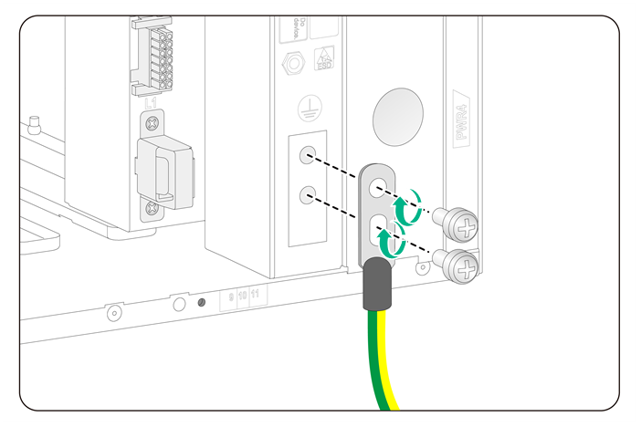
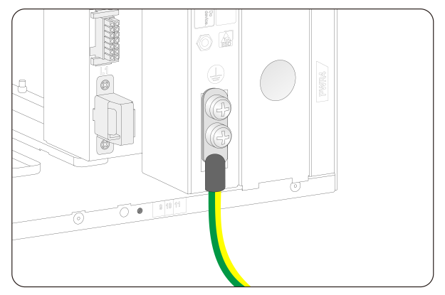
1. Remove the grounding screws from the grounding holes on the chassis.
2. Use grounding screws to attach the two-hole grounding lug of the grounding cable to the chassis.
3. Connect the ring terminal of the grounding cable to a grounding post of the grounding strip, and fasten the grounding cable to the grounding strip with the hex nut.
Figure2-4 Connecting the grounding cable
3 Installing modules
|
|
CAUTION: · Before connecting the device to a power source, install all modules. · To fasten a captive screw for a module, make sure the screwdriver bit matches the screw. Set the fastening torque to 5.5 kgf•cm (0.54 Nm) ± 10%. Keep the screwdriver bit steady and aligned with the screw and screw hole and press the screwdriver down into the screw. |
The module installation procedure is similar for the M9000-X06 and M9000-X10 gateways. The M9000-X06 gateway is used as an example in the following figures.
Installing MPUs
|
|
CAUTION: · The device provides two MPU slots. You can install one MPU, or two MPUs for 1+1 redundancy. · The device supports active/standby MPU switchover when you install two MPUs for the device. Make sure the active and standby MPUs are the same model. · If you install two MPUs for the device, you can hot swap the standby MPU. If you install only one MPU for the device, you cannot hot swap the MPU. · If you are not to install an MPU in an MPU slot, keep the filler panel in the slot. |
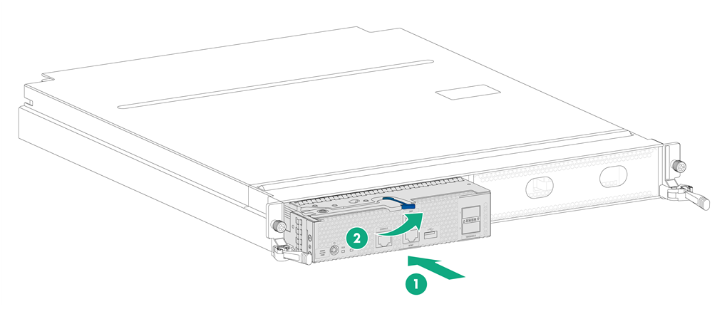
Installing an MPU for an M9000-X06/M9000-AI-X06 gateway
1. Use a Phillips screwdriver to loosen the captive screw on the filler panel in the target MPU slot. Then remove the filler panel from the slot..
2. Correctly orient the MPU, rotate the handle upward, and then push the MPU steadily into the slot along the guide rails.
3. Rotate the handle downward. Make sure the MPU makes close contact with the backplane.
4. Use a Phillips screwdriver to fasten the captive screw on the MPU.
Figure3-1 Installing an MPU for an M9000-X06/M9000-AI-X06 gateway
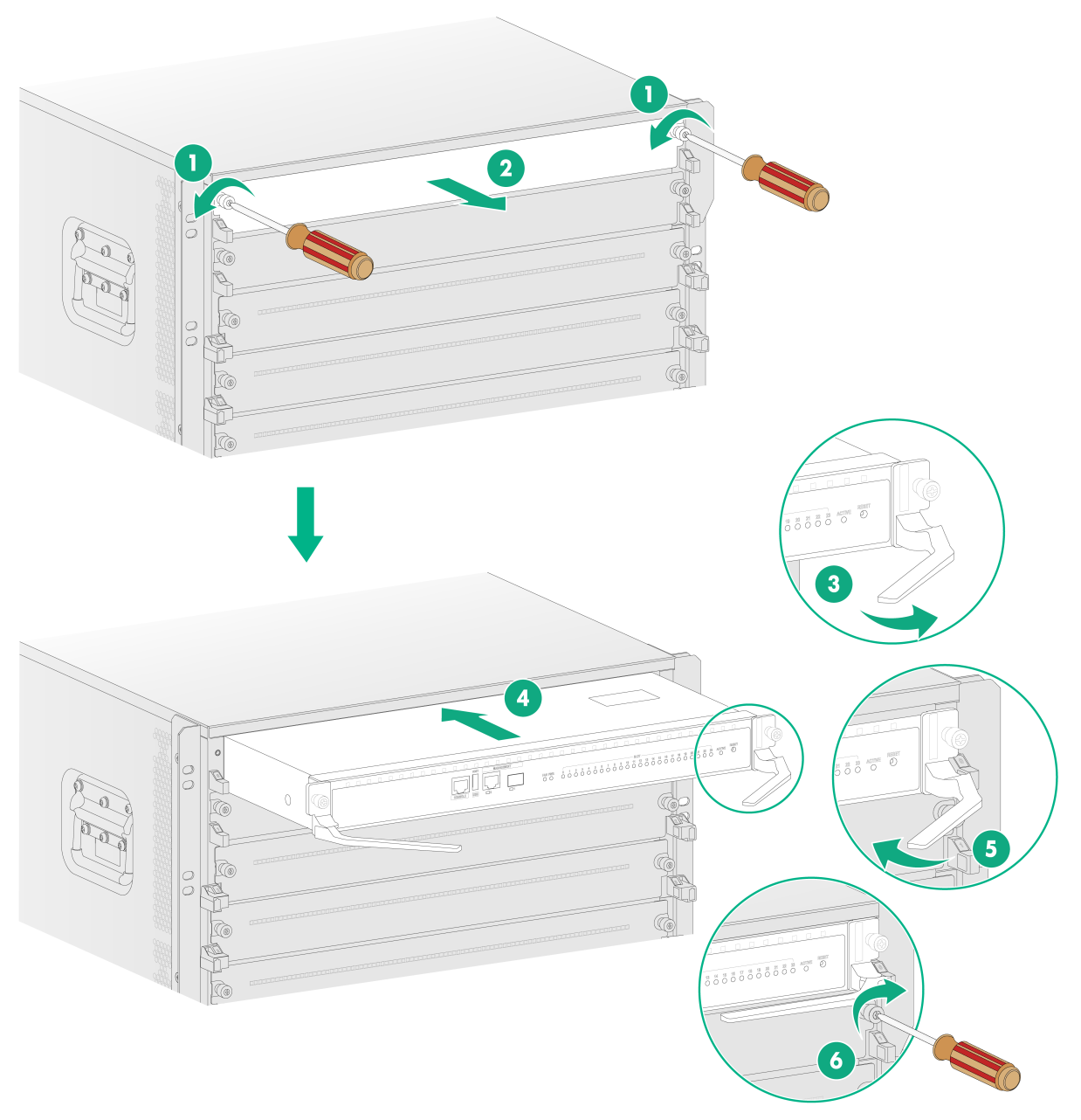
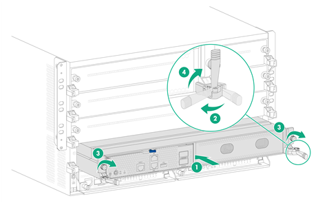
Installing an MPU for an M9000-X10/M9000-AI-X10 gateway
1. Remove the filler panel from the target MPU slot. Keep the removed filler panel secure for future use.
2. Correctly orient the MPU, insert it into the slot, and then push it steadily into the slot along the guide rails.
3. Fully open the ejector levers of the MPU.
4. Continue to push the MPU by its front panel until the ejector levers make close contact with the slot edges.
5. Close the ejector levers until they come in close contact with the MPU front panel.
6. Use a Phillips screwdriver to fasten the captive screws on the MPU.
Figure3-2 Installing an MPU for an M9000-X10/M9000-AI-X10 gateway
Installing switching fabric modules
|
|
CAUTION: When you install a switching fabric module, avoid damaging the connectors on it. |
|
|
IMPORTANT: · The M9000-X06 and M9000-AI-X06 gateways do not support hot swapping of switching fabric modules. The M9000-X10 and M9000-AI-X10 gateways supports hot swapping of switching fabric modules. · The M9000-X06 and M9000-AI-X06 gateways each provide six switching fabric module slots, but only slots 6 to 9 are available. Install a minimum of one switching fabric module if the device is installed with more than one interface switch module. If the device is installed with only one interface switch module, you can choose to not install any switching fabric modules. · The M9000-X10 and M9000-AI-X10 gateways each provide six switching fabric module slots, but only slots 10 to 13 are available. Install a minimum of one switching fabric module on the device. |
To install a switching fabric module:
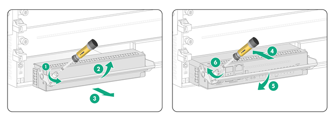
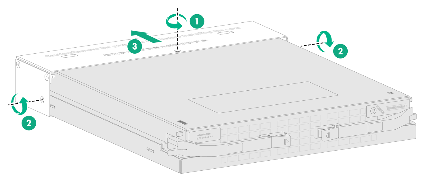
1. Remove the screws from the metal protection box attached to the switching fabric module and then remove the protection box.
Figure3-3 Removing the protection box from the switching fabric module
2. Remove the filler panel from the target switching fabric module slot.
Keep the removed filler panel secure for future use.
3. Press the locking tabs of the ejector levers to release the levers.
4. Correctly orient the switching fabric module. Align the switching fabric module with the target slot and insert it into the slot along the guide rails.
5. Continue to push the switching fabric module by its front panel until the ejector levers make close contact with the slot edges.
6. Close the ejector levers until the locking tabs lock the ejector levers in place.
Figure3-4 Installing a switching fabric module
Installing interface modules or firewall modules
|
|
CAUTION: · The firewall modules and interface modules are not hot swappable. To install a firewall module or interface module on the device, first install it on an interface switch module and then install the interface switch module on the device. · If you are not to install an interface module or firewall module in a slot on an interface switch module, keep the filler panel in the slot. |
The procedure is the same for installing an interface module or firewall module on an interface switch module. The following installs a firewall module.
To install an interface module on an interface switch module:
1. Remove the filler panel from the target slot. Put your forefinger and thumb into the hole of the filler panel, press the metal tab in the left hole, and then pull the filler panel out.
2. Open the ejector lever on the interface module and then push the module slowly into the slot along the guide rails until you cannot push it any further.
3. Close the ejector lever until the latch locks the ejector lever in place.
Figure3-5 Installing a firewall module on an interface switch module
4. Install the interface switch module in the device. For more information about installing the interface switch module, see "Installing interface switch modules."
Installing interface switch modules
|
|
CAUTION: If you are not to install an interface switch module in an interface switch module slot, keep the filler panel in the slot. |
The interface switch modules are hot swappable.
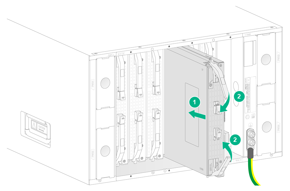
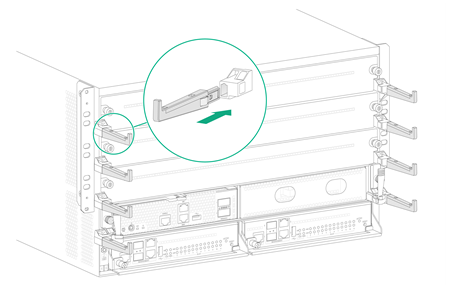
To install an interface switch module:
1. Remove the filler panel from the target interface switch module slot.
Keep the removed filler panel secure for future use.
Figure3-6 Removing the filler panel

2. Pivot down and open the ejector levers of the module. Gently push the module into the slot along the guide rails.
3. Continue to push the module by its front panel until you cannot push it any further.
4. Use a Phillips screwdriver to fasten the captive screws on the module.
5. Pivot up the ejector levers on the module.
Figure3-7 Installing the interface switch module
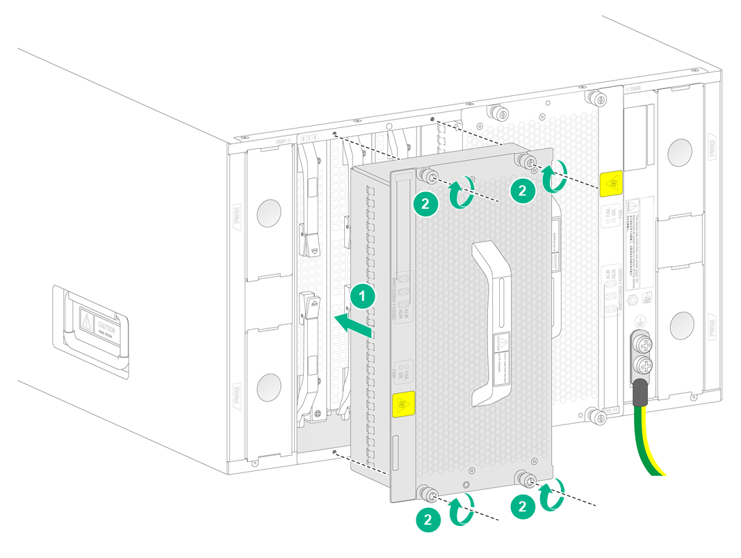
4 Installing fan trays
To install a fan tray in slot FAN1 on an M9000-X06 or M9000-AI-X06 gateway, orient the fan tray with the LEDs to the left of the handle. To install a fan tray in slot FAN2, orient the fan tray with the LEDs to the right of the handle.
To install a fan tray on an M9000-X10 or M9000-AI-X10 gateway, orient the fan tray with the LEDs above the handle.
To install a fan tray:
1. Correctly orient the fan tray and align the fan tray with the fan tray slot.
2. Holding the fan tray handles, steadily insert the fan tray way into the slot.
Keep the fan tray as steady as possible while inserting it into the slot.
3. Use a Phillips screwdriver to fasten the captive screws on the fan tray.
Figure4-1 Installing a fan tray
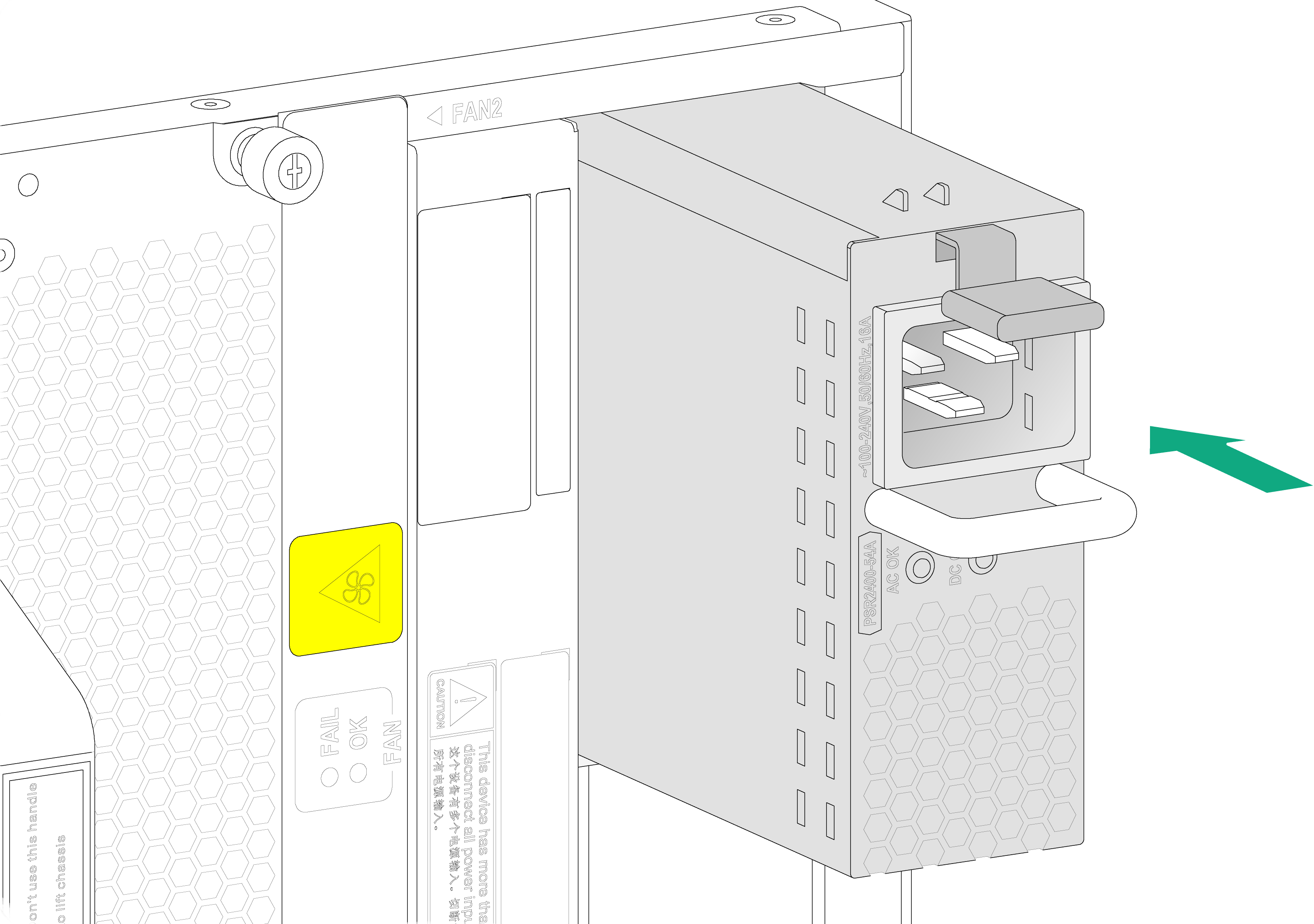
5 Installing power supplies
The power supply slots are located on the left and right sides of the chassis real panel. To install a power supply in a left power supply slot, orient the power supply with the latch above the handle. To install a power supply in a right power supply slot, orient the power supply with the latch below the handle.
The device supports AC power supplies, DC power supplies, and HVDC power supplies. The installation procedure is similar for the power supplies. This procedure installs an AC power supply.
To installing an AC power supply:
1. Put your forefinger into the hole in the filler panel and pull out the filler panel along the guide rails.
2. Correctly orient the power supply.
3. Align the power supply with the power supply slot. Then slide the power supply along the guide rails into the slot until the latch locks in place.
Figure5-1 Installing an AC power supply
6 Connecting a power cord
|
|
WARNING! · Provide a dedicated circuit breaker for each power input. · Before connecting a power cord, make sure the circuit breaker is turned off at the power input end. |
Connecting an AC power cord
1. Connect the female connector of the AC power cord to the AC input receptacle on the power supply.
2. Use a releasable cable tie to secure the power cord to the handle of the power supply
3. Connect the other end of the power cord to an AC power source.
Figure6-1 Connecting an AC power cord
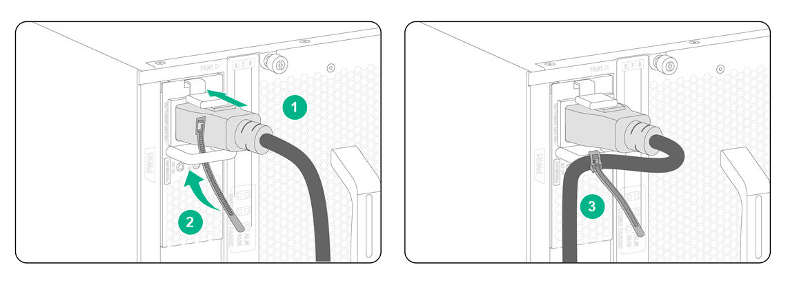
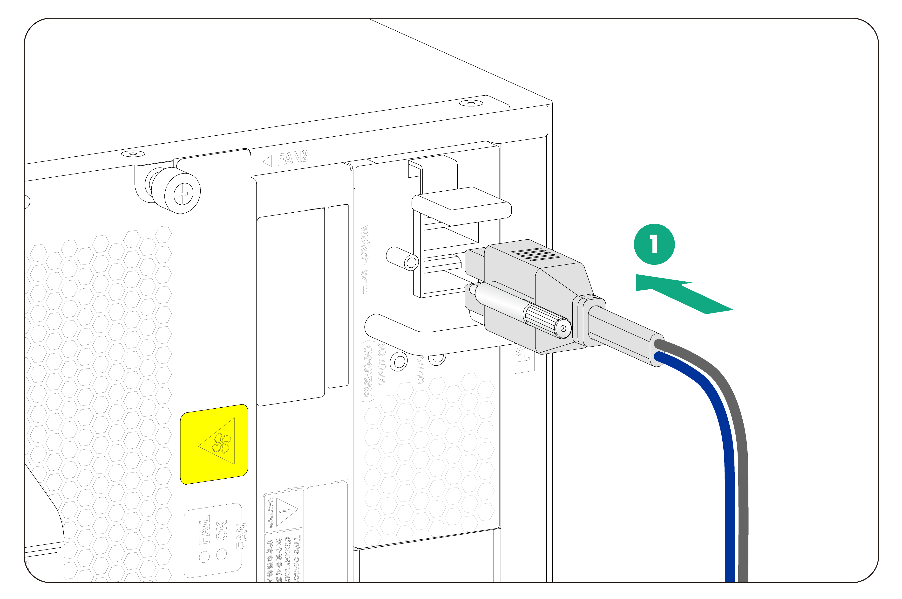
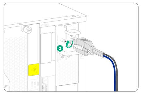
Connecting a DC power cord
|
|
WARNING! Before you connect a DC power cord, make sure the circuit breakers for both of the positive and negative power input wires are turned off. |
1. Connect the DC power cord connector to the DC input receptacle on the power supply.
2. Fasten the screw on the connector to secure the connector to the receptacle.
3. Connect the other ends of the DC power cords to a DC power source, with the positive wire (+) to the positive terminal and the negative wire (-) to the negative terminal.
Figure6-2 Connecting a DC power cord
Connecting an HVDC power cord
The connection procedure is similar for an AC power cord and an HVDC power cord. To connect an HVDC power cord, see "Connecting an AC power cord."
7 Installing cable management brackets
|
|
IMPORTANT: To prevent the cable management brackets from blocking the mounting bracket installation holes on the rack posts, install cable management brackets after the device is mounted in the rack. |
To install a cable management bracket, insert a cable guide to the cable guide hole in the pillow block.
Figure7-1 Cable management brackets
8 Connecting signal cables
Installing transceiver modules and fiber cables
|
|
WARNING! Disconnected optical fibers or transceiver modules might emit invisible laser light. Do not stare into beams or view directly with optical instruments when the device is operating. |
|
|
CAUTION: · Before installing a transceiver module, remove the fiber cables, if any, from it. For more information about installing transceiver modules, see the installation guide for the transceiver modules. · If you are not to use a fiber port or transceiver module, insert dust plugs into the port or module. If you are not to connect an optical fiber, install dust caps for the fiber connector. |
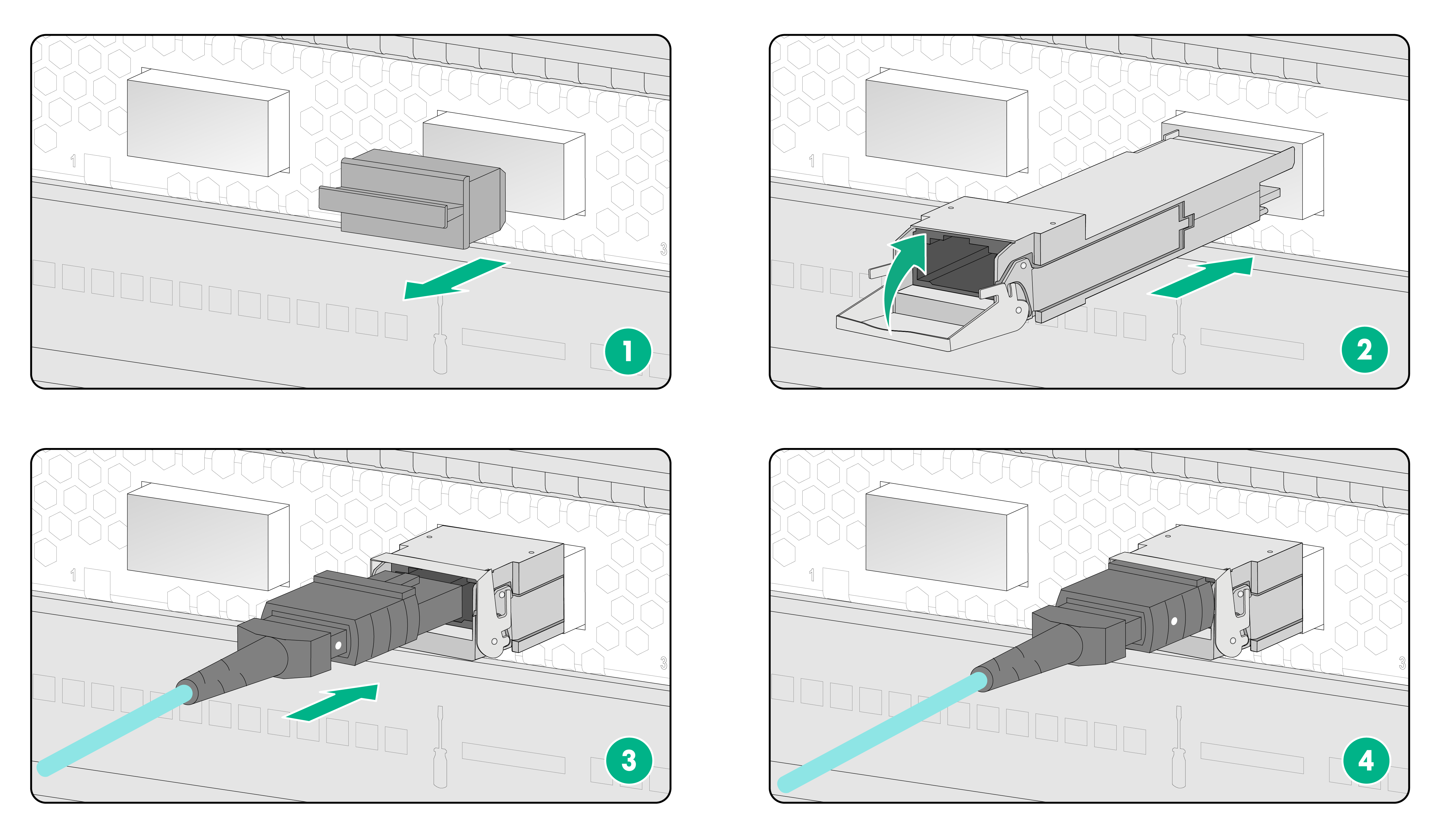
To install a transceiver module and fiber cable:
1. Remove the dust plug from the target fiber port.
2. Pull the bail latch on the transceiver module upwards.
Skip this step if the bail latch is plastic.
3. Take the transceiver module by its two sides and push the end without the bail latch gently into the port until it is firmly seated in the fiber port.
Routing signal cables
The cable management brackets are located on the left and right sides of the chassis front panel. As a best practice, route the cables from the left half of the chassis through the left cable management brackets and the cables from the right half of the chassis through the right cable management brackets.
1. Remove the dust plug and dust cap from the transceiver module and fiber connector, respectively.
2. Connect the fiber cable to the transceiver module.
¡ LC connector—Align the connector with the transceiver module and push it into the transceiver module slightly until it clicks into the place.
¡ MPO connector—Orient the connector with the white spot on it facing right. Insert the MPO fiber connector horizontally into the transceiver module. Push the MPO fiber connector into the transceiver module slightly until it clicks into the place.
3. Use cable ties to bind fiber cables every 150 mm (5.91 in).
4. Label fiber cables according to the cable labeling specifications.
Figure8-1 Installing a transceiver modules and fiber cable (with LC fiber connector)
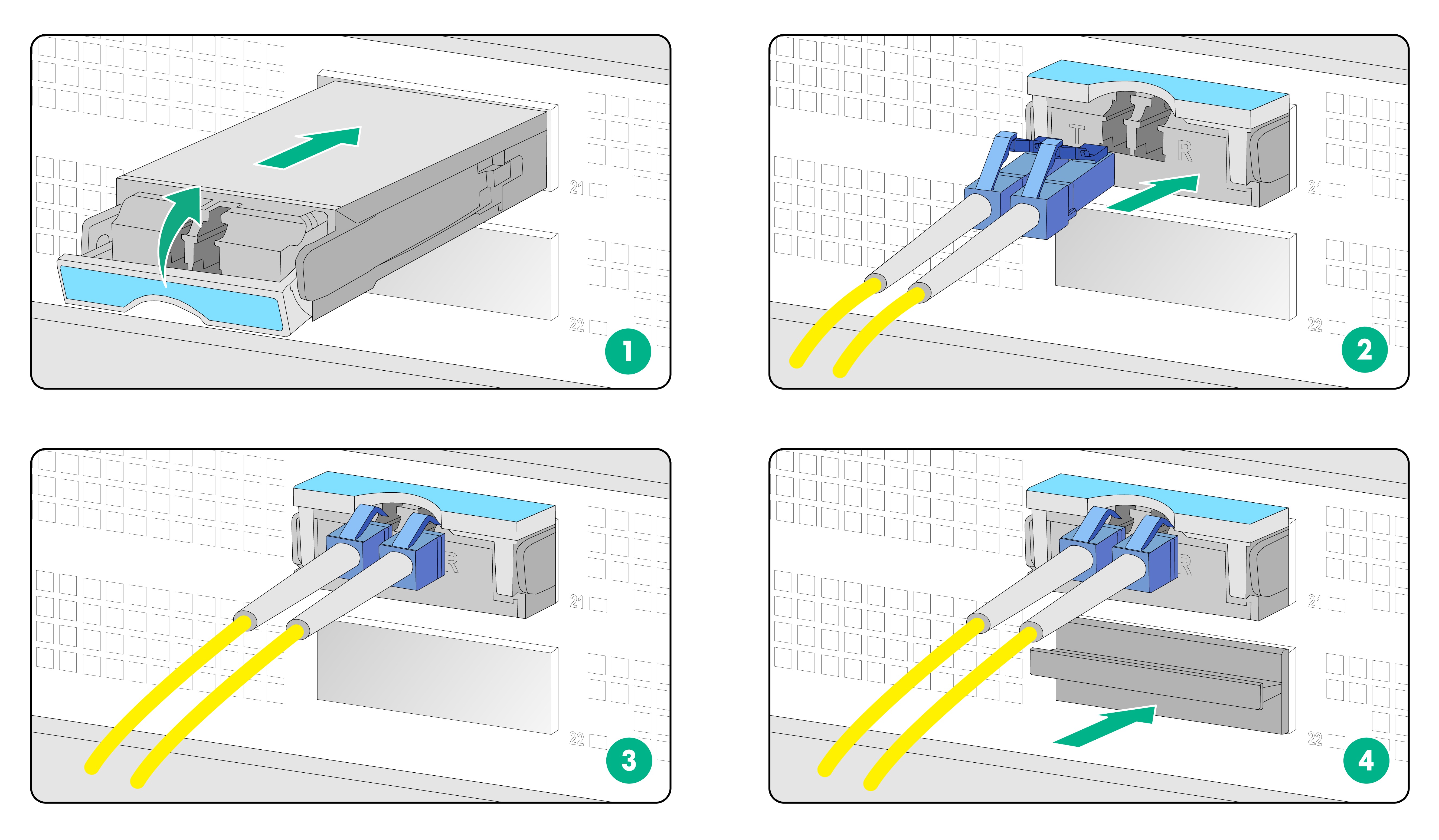
Figure8-2 Installing a transceiver modules and fiber cable (with MPO fiber connector)
9 Verifying the installation
Table9-1 Post-installation checklist
|
Item |
Requirements |
|
Installation site |
· No condensation on the surface of the device or inside of the device. · Keep the device clean and dust-free. · No packing boxes, packing bags or other packing materials left in the installation site. · Keep the air inlet and outlet vents of the device free of obstruction. |
|
Device |
· All modules are installed correctly. · No slot is empty. Each is installed with a module or filler panel, · Fan trays are installed correctly. |
|
Cables |
· The device is grounded reliably with the provided grounding cable. Both ends of the grounding cable are securely connected. · No switch or fuse is installed on the grounding cable. · The power cords are connected reliably and no short circuit has occurred in power input and output. · Power cords, grounding cables and fiber cables are routed and bound separately. · The cables are bound neatly with cable ties at an even distance. · The cable labels are correct, clear, and affixed to the cable in the same direction. |
|
Electricity safety |
A circuit breaker is provided for each power input line. |
10 Power-on check
|
|
WARNING! Locate the emergency power-off switch in the room before power-on so you can quickly shut power off when an electrical accident occurs. |
|
|
CAUTION: Before powering on the device, make sure all fan trays and modules are present. |
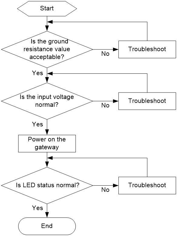
Power-on check flow
Figure10-1 Power-on check flow
Checking the LEDs
After the device powers up, you can determine whether the device and the components are operating correctly by observing the LEDs on the MPUs and other components.
The device MPU provides LEDs for modules installed on the device to indicate their operating status. Table 10-1 and Table 10-2 describe the LEDs on the MPUs. For more information about device LEDs, see the installation guide for the device.
Table10-1 M9000-X06 MPU LED description
|
LED |
Status |
Description |
|
|
Management Ethernet copper port LED/Management Ethernet fiber port LED |
Flashing |
A link is present on the port, and the port is sending or receiving data. |
|
|
On |
A link is present on the port. |
||
|
Off |
No link is present on the port. |
||
|
Fan tray status LED (FAN) |
OK |
FAIL |
|
|
On |
Off |
All fan trays are operating correctly. |
|
|
Off |
On |
A fan tray is faulty or no fan trays are present. |
|
|
Off |
Off |
The device is not powered on. |
|
|
Power supply status LED (PWR) |
OK |
FAIL |
|
|
On |
Off |
All power supplies are operating correctly. |
|
|
Off |
On |
One or more power supplies are faulty. |
|
|
Off |
Off |
The device is not powered on. |
|
|
Slot status LED (SLOT) |
RUN |
ALM |
|
|
Flashing (4 Hz) |
On |
The module is loading software. If the LED stays in this status, the software version of the device does not match that of the module. |
|
|
Flashing (0.5 Hz) |
Off |
The module is operating correctly. |
|
|
Flashing (0.5 Hz) |
Flashing (0.25 Hz) |
The temperature of the module has reached the high-temperature warning threshold or dropped below the low-temperature threshold. |
|
|
On |
On |
The module is starting up or faulty. |
|
|
Off |
Off |
The module is not present. |
|
|
Active/standby status LED (ACTIVE) |
On |
The MPU is operating in active mode. |
|
|
Off |
· The MPU is operating in standby mode. · The MPU is faulty. Examine also the status LED for the MPU to determine whether a fault has occurred. |
||
Table10-2 M9000-X10 MPU LED description
|
LED |
Status |
Description |
|
|
Management Ethernet copper port LED/Management Ethernet fiber port LED |
Flashing |
A link is present on the port, and the port is sending or receiving data. |
|
|
On |
A link is present on the port. |
||
|
Off |
No link is present on the port. |
||
|
Fan tray status LED (FAN) |
OK |
FAIL |
|
|
On |
Off |
All fan trays are operating correctly. |
|
|
Off |
On |
A fan tray is faulty or no fan trays are present. |
|
|
Off |
Off |
The device is not powered on. |
|
|
Power supply status LED (PWR) |
OK |
FAIL |
|
|
On |
Off |
All power supplies are operating correctly. |
|
|
Off |
On |
One or more power supplies are faulty. |
|
|
Off |
Off |
The device is not powered on. |
|
|
Slot status LED (SLOT) |
RUN |
ALM |
|
|
Flashing (4 Hz) |
On |
The module is loading software. If the LED stays in this status, the software version of the device does not match that of the module. |
|
|
Flashing (0.5 Hz) |
Off |
The module is operating correctly. |
|
|
Flashing (0.5 Hz) |
Flashing (0.25 Hz) |
The temperature of the module has reached the high-temperature warning threshold or dropped below the low-temperature threshold. |
|
|
On |
On |
The module is starting up or faulty. |
|
|
Off |
Off |
The module is not present. |
|
|
Active/standby status LED (ACTIVE) |
On |
The MPU is operating in active mode. |
|
|
Off |
· The MPU is operating in standby mode. · The MPU is faulty. Examine also the status LED for the MPU to determine whether a fault has occurred. |
||
11 Appendix A Chassis views
This document is applicable to H3C SecPath M9000-X multiservice security gateway series and H3C SecPath M9000-AI-X multiservice security gateway series.
Table11-1 H3C SecPath M9000-X and M9000-AI-X multiservice security gateway series models
|
Gateway series |
Model |
|
M9000-X |
M9000-X06 |
|
M9000-X10 |
|
|
M9000-AI-X |
M9000-AI-X06 |
|
M9000-AI-X10 |
The main components of the device include supervisor engine modules (also called MPUs), interface switch modules, interface modules, firewall modules, switching fabric modules, fan trays, and power supplies.
M9000-X06/M9000-AI-X06
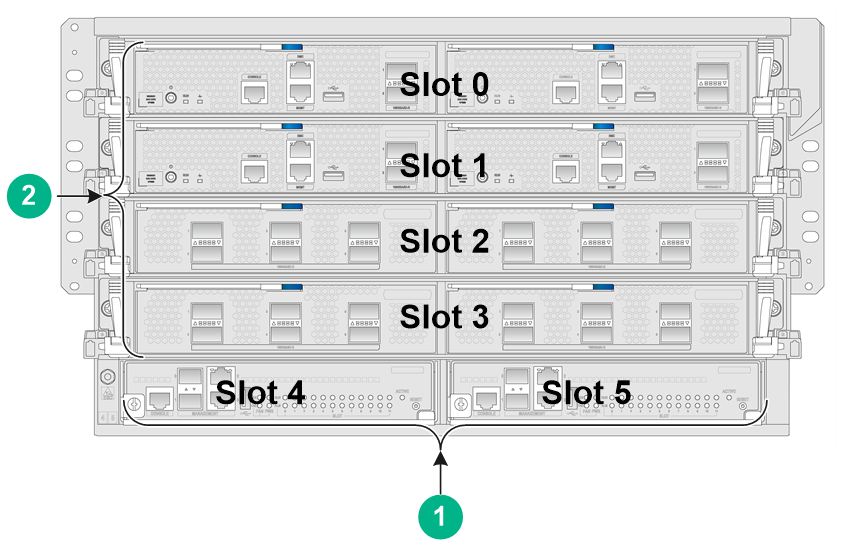
Figure11-1 Front view
|
(1) MPU section |
(2) Interface switch module section |
Figure11-2 Rear view
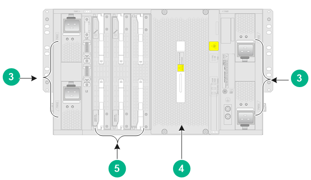
|
(3) Power supply section |
(4) Fan tray section |
|
(5) Switching fabric module section |
|
Table11-2 Descriptions for the M9000-X06/M9000-AI-X06 sections
|
Section |
Slots |
Remarks |
|
MPU section |
Slots 4 and 5 |
N/A |
|
Interface switch module section |
Slots 0 to 3 |
An interface switch module provides two slots in which you can install firewall modules or interface modules. |
|
Power supply section |
Power supply slots PWR1 to PWR4 |
· Determine the power supply model based on power distribution. · Determine the number of power supplies based on the power requirement of the device. |
|
Fan tray section |
Fan tray slots FAN1 and FAN2 |
N/A |
|
Switching fabric module section |
Slots 6 to 11 |
· Slot numbers of switching fabric modules are located at the top left corner and lower right corner of the switching fabric module section. · You can install switching fabric modules only in slots 6 to 9. · Install a minimum of one switching fabric module if the device is installed with more than one interface switch module. If the device is installed with only one interface switch module, you can choose to not install any switching fabric modules. |
M9000-X10/M9000-AI-X10
Figure11-3 Front view
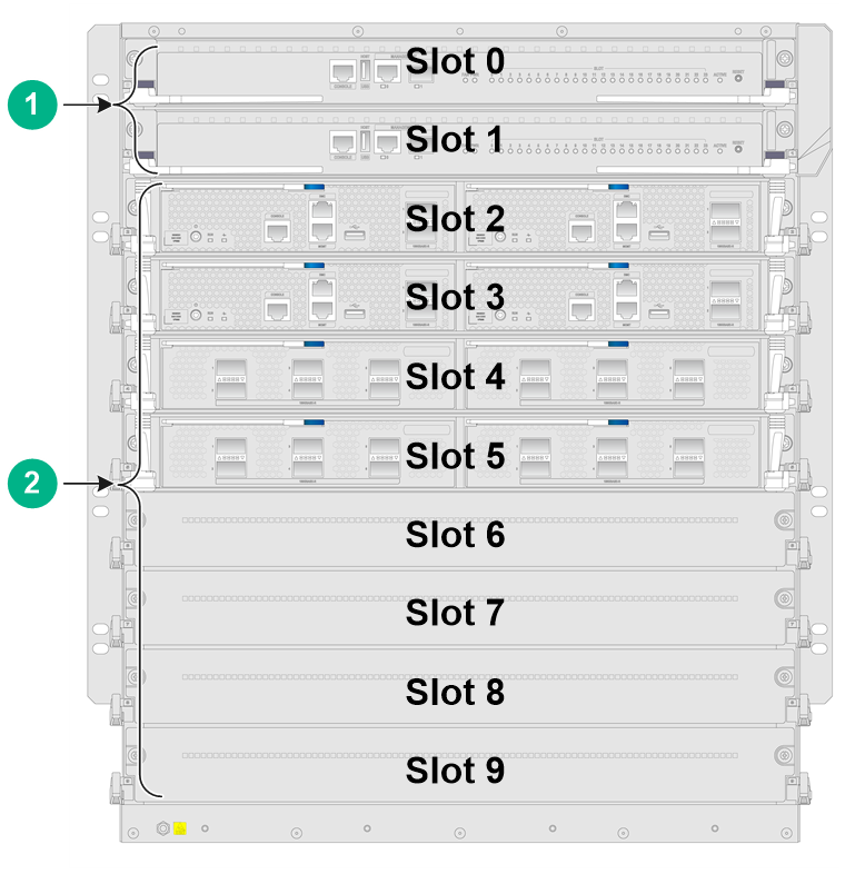
|
(1) MPU section |
(2) Interface switch module section |
Figure11-4 Rear view
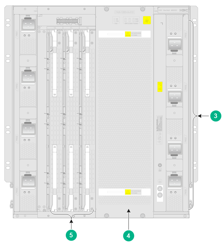
|
(3) Power supply section |
(4) Fan tray section |
|
(5) Switching fabric module section |
|
Table11-3 Descriptions for the M9000-X10/M9000-AI-X10 sections
|
Section |
Slots |
Remarks |
|
MPU section |
Slots 0 and 1 |
N/A |
|
Interface switch module section |
Slots 2 to 9 |
· An interface switch module provides two slots in which you can install firewall modules and interface modules. · Interface modules and firewall modules are not hot swappable. You must first install them on an interface switch module and then install the interface switch module on the device. |
|
Power supply section |
Power supply slots PWR1 to PWR8 |
· Determine the power supply model based on power distribution. · Determine the number of power supplies based on the power requirement of the device. |
|
Fan tray section |
Fan tray slots FAN1 and FAN2 |
N/A |
|
Switching fabric module section |
Slots 10 to 15 |
· Slot numbers of switching fabric modules are located at the top left corner and lower right corner of the switching fabric module section. · You can install switching fabric modules only in slots 10 to 13. · Install a minimum of one switching fabric module on the device. |
