- Table of Contents
- Related Documents
-
| Title | Size | Download |
|---|---|---|
| 01-Hardware Information and Specifications | 30.10 MB |
Contents
Service module naming conventions
Fabric module naming conventions
Restrictions and guidelines for service modules
LSXM116XFANH (high performance)
LSXM108XFANH (high performance)
LSXM104XFANH (high performance)
Making an Ethernet twisted pair cable
QSFP+ to SFP+/QSFP28 to SFP28 DAC cable
1 Chassis
H3C S12500G-AF switch series is a set of core switching products designed for the cloud computing data centers. It uses the advanced multi-stage multi-plane CLOS architecture to deliver the industry's highest switching performance, port density, availability, and most abundant cloud computing features.
Chassis information
Chassis views
H3C S12500G-AF switch series includes the S12504G-AF, S12508G-AF, and S12516G-AF models.
Unless otherwise stated, MPUs, service modules, and fabric modules are collectively referred to as "modules" in this document.
|
|
NOTE: The chassis views in this section are for illustration only. |
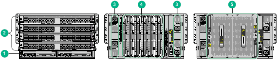
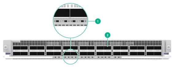
Figure1-1 Front and rear views of the S12504G-AF switch
|
(1) MPU section |
(2) Service module section |
(3) Power module section |
|
(4) Fabric module section |
(5) Fan tray section |
|
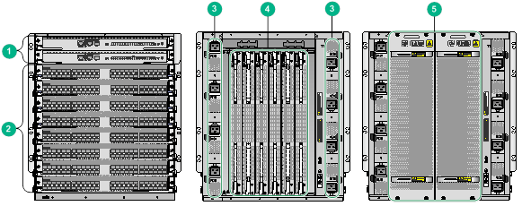
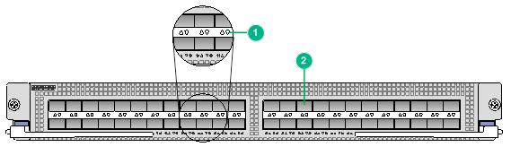
Figure1-2 Front and rear views of the S12508G-AF switch
|
(1) MPU section |
(2) Service module section |
(3) Power module section |
|
(4) Fabric module section |
(5) Fan tray section |
|
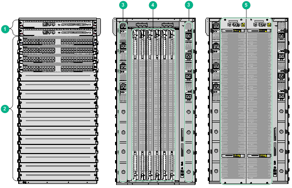
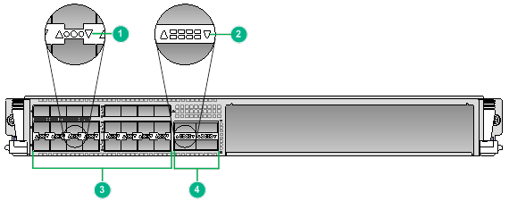
Figure1-3 Front and rear views of the S12516G-AF switch
|
(1) MPU section |
(2) Service module section |
(3) Power module section |
|
(4) Fabric module section |
(5) Fan tray section |
|
Table1-1 Description for the switch sections
|
Section |
Location identification |
Installation description |
|
MPU section |
Pink color is used for you to identify the MPU installation location. · S12516G-AF and S12508G-AF—The ejector lever pillow blocks on the MPU slots are pink marked. The MPU ejector levers are also pink marked to suggest the corresponding installation location. · S12504G-AF—The MPU slot numbers on the chassis are pink marked. The module identifiers on the MPUs are also pink marked to suggest the corresponding installation location. NOTE: The MPU section of an S12504G-AF is located below the service module section. |
No MPUs are provided with the switch. Purchase MPUs yourself. The switch has two MPU slots. You can install one MPU, or two MPUs for redundancy. To install only one MPU for the switch, you can install it in either of the MPU slots. |
|
Service module section |
The ejector lever pillow blocks on service module slots are purple marked. The edges and ejector levers of service modules are also purple marked to suggest the corresponding installation location. |
No service modules are provided with the switch. Purchase service modules yourself. · S12516G-AF switch—16 service module slots. · S12508G-AF switch—8 service module slots. · S12504G-AF switch—4 service module slots. You can install a service module in any of the empty service module slots. |
|
Power module section |
N/A |
No power modules are provided with the switch. Purchase power modules yourself. · S12516G-AF switch—16 power module slots, with eight on the left side and eight on the right side of the rear panel. · S12508G-AF switch—8 power module slots, with four on the left side and four on the right side of the rear panel. · S12504G-AF switch—4 power module slots, with two on the left side and two on the right side of the rear panel. The switch supports N+N (dual power input sources) and N+1 (single power input source) power redundancy. Determine the number of power modules based on power supply mode and the system power consumption. You can install a power module in any of the empty power module slots. |
|
Fabric module section |
The fabric module slots are behind fan trays. Each fan tray covers three fabric module slots. |
No fabric modules or fabric module slot filler panels are provided with the switch. Purchase fabric modules and fabric module slot filler panels yourself. · Configure two to six fabric modules for the switch. Install filler panels in the empty fabric module slots. · Before you remove a fabric module, remove the fan tray that covers it. |
|
Fan tray section |
The fan tray section is located at the rear of the chassis. |
No fan trays are provided with the switch. Purchase fan trays yourself. The switch provides two fan tray slots FAN1 and FAN2. You must install two fan trays on the switch. Replace a fan tray only when the other fan tray is operating correctly. |
Slot arrangement
Table1-2 Slot quantity for the removable components
|
Item |
S12504G-AF |
S12508G-AF |
S12516G-AF |
|
MPU slots |
2 |
2 |
2 |
|
Service module slots |
4 |
8 |
16 |
|
Fabric module slots |
6 |
6 |
6 |
|
Power module slots |
4 |
8 |
16 |
|
Fan tray slots |
2 |
2 |
2 |
Figure1-4 S12504G-AF slot arrangement
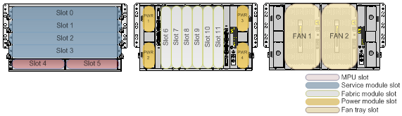
Figure1-5 S12508G-AF slot arrangement
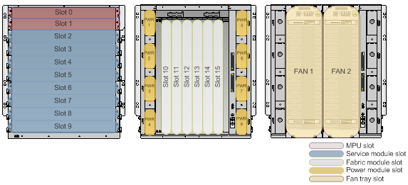
Figure1-6 S12516G-AF slot arrangement
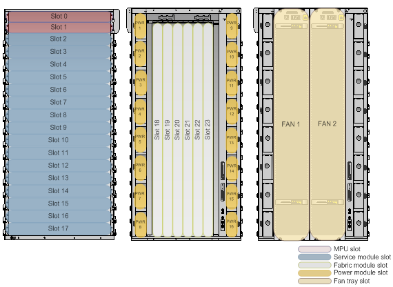
Table1-3 describes the slot arrangement for the removable components.
Table1-3 Slot arrangement for the removable components
|
Model |
MPU |
Service module |
Fabric module |
Power module |
Fan tray |
|
S12516G-AF |
Slots 0 and 1 |
Slots 2 to 17 |
Slots 18 to 23 Slots 18 to 20 are covered by FAN 1. Slots 21 to 23 are covered by FAN 2. |
PWR1 to PWR16 |
FAN1 and FAN2 |
|
S12508G-AF |
Slots 0 and 1 |
Slots 2 to 9 |
Slots 10 to 15 Slots 10 to 12 are covered by FAN 1. Slots 13 to 15 are covered by FAN 2. |
PWR1 to PWR8 |
FAN1 and FAN2 |
|
S12504G-AF |
Slots 4 and 5 |
Slots 0 to 3 |
Slots 6 to 11 Slots 6 to 8 are covered by FAN 1. Slots 9 to 11 are covered by FAN 2. |
PWR1 to PWR4 |
FAN1 and FAN2 |
Chassis specifications
Table1-4 Chassis specifications
|
Item |
S12504G-AF |
S12508G-AF |
S12516G-AF |
|
Power supply mode |
· AC · Low-voltage DC · High-voltage DC |
· AC · Low-voltage DC · High-voltage DC |
· AC · Low-voltage DC · High-voltage DC |
|
Product compliance |
· Safety standards · EMC standards |
· Safety standards · EMC standards |
· Safety standards · EMC standards |
|
MPU redundancy |
1+1 |
1+1 |
1+1 |
|
Fabric module redundancy |
N+M |
N+M |
N+M |
|
Power module redundancy |
· N+N · N+1 |
· N+N · N+1 |
· N+N · N+1 |
|
Heat dissipation method |
Air cooling |
Air cooling |
Air cooling |
|
Maximum number of 400GE ports |
64 |
128 |
256 |
|
Maximum number of 100GE ports |
144 |
288 |
576 |
|
Maximum number of 40GE ports |
144 |
288 |
576 |
|
Maximum number of 25GE ports |
192 |
384 |
768 |
|
Maximum number of 10GE ports |
192 |
384 |
768 |
|
Maximum number of GE ports |
192 |
384 |
768 |
Weights and dimensions
Table1-5 Chassis weights and dimensions
|
Model |
Net weight (without package materials) |
Net weight (with package materials) |
Max weight (fully configured) |
Height |
Width |
Depth |
|
S12516G-AF |
86.1 kg (189.81 lb) |
119.3 kg (263.01 lb) |
< 360 kg (793.65 lb) |
Without package materials |
||
|
931 mm (36.65 in)/21 RUs |
440 mm (17.32 in) |
857 mm (33.74 in) |
||||
|
With package materials |
||||||
|
1288 mm (50.71 in) |
750 mm (29.53 in) |
1185 mm (46.65 in) |
||||
|
S12508G-AF |
47.0 kg (103.62 lb) |
93.2 kg (205.47 lb) |
< 200 kg (440.92 lb) |
Without package materials |
||
|
531 mm (20.91 in)/12 RUs |
440 mm (17.32 in) |
857 mm (33.74 in) |
||||
|
With package materials |
||||||
|
888 mm (34.96 in) |
750 mm (29.53 in) |
1185 mm (46.65 in) |
||||
|
S12504G-AF |
36.0 kg (79.37 lb) |
68.0 kg (149.91 lb) |
< 115 kg (253.53 lb) |
Without package materials |
||
|
264 mm (10.39 in)/6 RUs |
440 mm (17.32 in) |
857 mm (33.74 in) |
||||
|
With package materials |
||||||
|
623 mm (24.53 in) |
750 mm (29.53 in) |
1185 mm (46.65 in) |
||||
|
|
NOTE: · Rack height is measured in RUs. One RU is 44.45 mm (1.75 in). · Table1-5 lists dimensions for the switch, excluding the mounting brackets, cable management brackets, modules, and power modules. |
System power consumption
The system power consumption of the switch depends on the type and number of modules and the fan tray power consumption.
· The minimum system power consumption is the total static power consumption of all modules plus the minimum fan tray power consumption.
· The typical system power consumption is the total typical power consumption of all modules plus the typical fan tray power consumption.
· The maximum system power consumption is the total dynamic power consumption of all modules plus the maximum fan tray power consumption.
For example, for an S12516G-AF switch that has two LSXM3SUPS2 MPUs, two LSXM3TGS48SF2 service modules, six LSXM3SFS16G2 fabric modules, and two LSXM116XFAN fan trays, the system power consumption is calculated as follows:
· The minimum system power consumption of the switch is 2 × 39 + 2 × 95 + 6 × 241 + 2 × 33 = 1780 W.
· The typical system power consumption of the switch is 2 × 40 + 2 × 101 + 6 × 317 + 2 × 206 = 2596 W.
· The maximum system power consumption of the switch is 2 × 50 + 2 × 175 + 6 × 500 + 2 × 793 = 5036 W.
Reliability and availability
Table1-6 Reliability and availability
|
Model |
Mean Time Between Failure (MTBF) (year) |
Mean time to repair (MTTR) (hour) |
Availability |
|
S12516G-AF |
44.62 |
0.5 |
0.9999974 |
|
S12508G-AF |
44.63 |
0.5 |
0.9999974 |
|
S12504G-AF |
46.26 |
0.5 |
0.9999975 |
Heat dissipation
Heat dissipation is measured in BTU/h, and 1 W equals 3.4121 BTU/h.
The heat dissipation of a switch depends on its power consumption. To calculate heat dissipation of the switch, assume 90% power consumption is converted to heat, and the conversion efficiency of the power modules is 90%. Heat dissipation/hour of the switch is 0.9 × (total power consumption of the modules plus power consumption of the fan tray)/0.9 × 3.4121.
Table1-7 Heat dissipation
|
Model |
Heat dissipation (BTU/h) |
|
S12516G-AF |
19539 |
|
S12508G-AF |
39931 |
|
S12504G-AF |
76922 |
Environmental specifications
Table1-8 Environmental specifications
|
Description |
Operating |
Storage |
|
Temperature |
0°C to 40°C (32°F to 104°F) |
–40°C to +70°C (–40°F to +158°F) |
|
Relative humidity |
5% to 95%, noncondensing |
5% to 95%, noncondensing |
|
Altitude |
–60 m to +5000 m (–196.85 ft to +16404.20 ft) The maximum acceptable temperature decreases by 0.33°C (32.59°F) for every 100 m (328.08 ft) increase in altitude from Tmax@0m. |
–60 m to +5000 m (–196.85 ft to +16404.20 ft) |
Noise
The switch uses fan trays that can automatically adjust the fan speed based on the switch temperature. The sound pressure levels vary by fan speed. For more information, see Table1-9.
Table1-9 Sound pressure levels
|
Switch model |
Fan tray model |
Sound pressure level in the acceptable temperature range |
Sound pressure level when the fan tray operates at full speed |
|
S12516G-AF (with two fan trays) |
LSXM116XFANH |
73.9 dBA |
97.4 dBA |
|
LSXM116XFAN |
67.8 dBA |
91.2 dBA |
|
|
S12508G-AF (with two fan trays) |
LSXM108XFANH |
71.5 dBA |
95.4 dBA |
|
LSXM108XFAN |
62.1 dBA |
87.6 dBA |
|
|
S12504G-AF (with two fan trays) |
LSXM104XFANH |
69.2 dBA |
87.0 dBA |
|
LSXM104XFAN |
67.5 dBA |
85.3 dBA |
|
|
NOTE: The sound pressure levels are measured based on the method specified in ISO 7779 at bystander positions. |
Rack requirements
The switch is applicable to all 19-inch standard racks. For information about how to select and install a rack, see Universal Cabinet and Accessories Installation Guide.
Slide rails
No slide rails are shipped with the switch. Select slide rails for the switch as required. Table1-10 describes the slide rails available for the switch.
Table1-10 Slide rails available for the switch
|
Switch model |
Max. chassis weight (fully configured) |
Applicable slide rails |
||
|
Slide rail model |
Adjustment range |
Occupied space |
||
|
S12516G-AF |
360 kg (793.65 lb) |
LSXM1BSR |
630 mm to 900 mm (24.80 in to 35.43 in) |
1 RU |
|
S12508G-AF |
200 kg (440.92 lb) |
LSXM1BSR |
630 mm to 900 mm (24.80 in to 35.43 in) |
1 RU |
|
LSTM2KSGD0 |
500 mm to 800 mm (19.69 in to 31.50 in) |
2 RUs |
||
|
S12504G-AF |
115 kg (253.53 lb) |
LSVM1BSR10 |
630 mm to 850 mm (24.80 in to 33.46 in) |
N/A |
Chassis ordering information
To purchase an S12500G-AF chassis, contact the sales agent or H3C sales personnel.
Table1-11 S12500G-AF chassis ordering information
|
Product code |
Product name |
Description |
|
0235A3EW |
S12516G-AF |
H3C S12516G-AF Ethernet switch host |
|
0235A3EV |
S12508G-AF |
H3C S12508G-AF Ethernet switch host |
|
0235A2LD |
S12504G-AF |
H3C S12504G-AF Ethernet switch host |
2 Modules
|
|
IMPORTANT: · Type-S modules include Type-S MPUs (for example, LSXM1SUPS2), Type-S fabric modules (for example, LSXM1SFS08D2), and Type-S service modules (for example, LSXM1TGS48SE2). A Type-S module can be used together only with another Type-S module. You cannot install a Type-S module and a module of another type on the same switch. · Type-T modules include Type-T MPUs (for example, LSXM2SUPT2), Type-T fabric modules (for example, LSXM2SFT08E2), and Type-T service modules (for example, LSXM1TGS48TE2). A Type-T module can be used together only with another Type-T module. You cannot install a Type-T module and a module of another type on the same switch. · You cannot use the speed command to change the speed of a split interface on a module. · You can only use QSFP+ to SFP+ cables for 10GE interfaces split from a 100GE interface. |
|
|
NOTE: For the transceiver modules and cables available for the modules, see H3C S12500G-AF Switch Series Cards and Transceiver Modules Compatibility Matrixes. |
|
|
NOTE: Module dimensions are expressed in Height (H) × Width (W) × Depth (D) format: · Height—Height of the front panel of the module. · Width—Width of the front panel of the module. · Depth—Depth from the front panel of the module to the connector (including the connector, but excluding the ejector levers and captive screws). |
The switch supports varieties of modules that are different in power consumptions. For a same module, the power consumption varies by its state.
· The minimum power consumption of a module refers to the power consumed by the module when it is running with all its ports down and its fiber ports not installed with transceiver modules.
· The typical power consumption of a module refers to the power consumed by the module when it is running with 50% of its ports connected and at 50% load.
· The maximum power consumption of a module refers to the power consumed by the module when it is running with all of its ports connected and at full load.
Naming conventions
MPU naming conventions
Figure2-1 MPU naming conventions
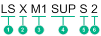
Table2-1 MPU naming conventions
|
No. |
Description |
|
1 |
Product line. LS represents the switch product line. |
|
2 |
Product series. X represents the S12500G-AF switch series. |
|
3 |
Distinguisher. |
|
4 |
Module type. |
|
5 |
MPU type. Values include: · S—Type-S MPU. · T—Type-T MPU. |
|
6 |
Extended attributes. |
Service module naming conventions
Figure2-2 Service module naming conventions

Table2-2 Service module naming conventions
|
No. |
Description |
|
1 |
Product line. LS represents the switch product line. |
|
2 |
Product series. X represents the S12500G-AF switch series. |
|
3 |
Distinguisher. |
|
4 |
Primary interface rate of the service module. |
|
5 |
Primary interface type of the service module. |
|
6 |
Primary interface quantity of the service module. |
|
7 |
Optional. Secondary interface type of the service module. |
|
8 |
Service module type. |
|
9 |
Extended attributes. |
Fabric module naming conventions
Figure2-3 Fabric module naming conventions
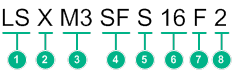
Table2-3 Fabric module naming conventions
|
No. |
Description |
|
1 |
Product line. LS represents the switch product line. |
|
2 |
Product series. X represents the S12500G-AF switch series. |
|
3 |
Distinguisher. |
|
4 |
Module type. SF represents the fabric module. |
|
5 |
Fabric module type. Values include: · S—Type-S fabric module. · T—Type-T fabric module. |
|
6 |
Compatible switch model. 16 represents that the fabric module is compatible with the S12516G-AF switch. |
|
7 |
Fabric module class. |
|
8 |
Extended attributes. |
MPUs
|
|
IMPORTANT: · To verify compatibility of the module with the software release you are using, see the release notes. · The USB port outputs power as prescribed by USB 2.0. You can only install a USB 2.0-compliant device in the USB port. · Set the same speed and duplex mode for a management Ethernet port and its peer port. · If the two management ports are connected to one remote switch, you must assign their peer ports to different VLANs. Login or file transfer will fail if the peer ports are in the same VLAN. · When using the BootWare menu to upgrade software or BootWare, make sure you use 10/100/1000BASE-T port M0/0/0 for image transferring. · Type-S modules include Type-S MPUs (for example, LSXM1SUPS2), Type-S fabric modules (for example, LSXM1SFS08D2), and Type-S service modules (for example, LSXM1TGS48SE2). A Type-S module can be used together only with another Type-S module. You cannot install a Type-S module and a module of another type on the same switch. · Type-T modules include Type-T MPUs (for example, LSXM2SUPT2), Type-T fabric modules (for example, LSXM2SFT08E2), and Type-T service modules (for example, LSXM1TGS48TE2). A Type-T module can be used together only with another Type-T module. You cannot install a Type-T module and a module of another type on the same switch. |
The switch uses an MPU for control and management. You can install one MPU, or two MPUs for redundancy on the switch. Do not install MPUs of different models on the same switch.
Table2-4 Type-T MPU ordering guide
|
MPU model |
Applicable switch models |
|
LSXM2SUPT2 |
S12516G-AF S12508G-AF |
|
LSXM1SUP04T2 |
S12504G-AF |
Table2-5 Type-S MPU ordering guide
|
Available MPUs |
Applicable switch models |
|
LSXM3SUPS2 |
S12516G-AF S12508G-AF |
|
LSXM1SUPS2 |
S12508G-AF |
|
LSXM3SUP04S2 |
S12504G-AF |
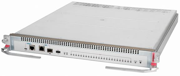
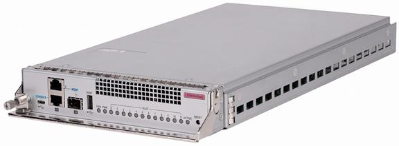
LSXM2SUPT2
View
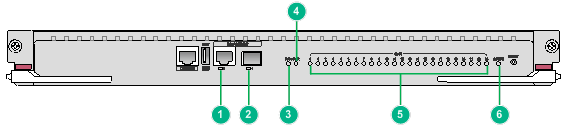
Figure2-4 LSXM2SUPT2 MPU view
Technical specifications
Table2-6 Technical specifications
|
Item |
Specification |
|
Net weight |
4.90 kg (10.80 lb) |
|
Dimensions (H × W × D) |
44 × 433 × 512 mm (1.73 × 17.05 × 20.16 in) |
|
Power consumption |
· Minimum: 28 W · Maximum: 34 W |
|
Processor |
4 cores, 2.2 GHz |
|
SDRAM |
16 GB |
|
Flash |
8 GB |
|
NVRAM |
512 KB |
|
Hot swapping |
Supported |
|
Connector type |
· RJ-45 · LC · USB (Type A) |
|
Ports |
· 1 × console port · 1 × USB port (USB 2.0, Host) · 2 × network management ports (one RJ-45 port and one SFP port) |
|
Port transmission speed |
· Console port: 9600 bps (default) to 115200 bps · RJ-45 management port: 10/100/1000 Mbps, half/full duplex · SFP management port: 1000 Mbps |
|
Applicable switch models |
All S12500G-AF models |
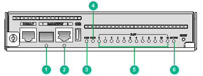
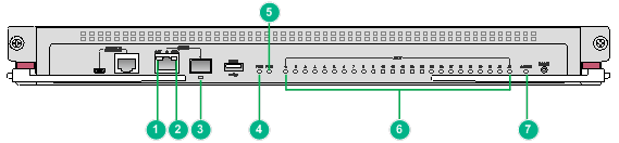
Ports and LEDs
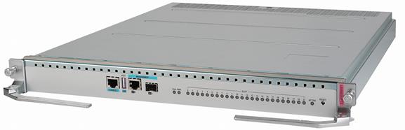
Figure2-5 LSXM2SUPT2 front panel
|
(1) 10/100/1000BASE-T management Ethernet port LED |
(2) SFP management Ethernet port LED |
|
(3) Fan tray status LED (FAN) |
(4) Power module status LED (PWR) |
|
(5) Module status LEDs (SLOT) |
(6) MPU active/standby status LED (ACTIVE) |
|
LED |
Status |
Description |
|
Management Ethernet port LED |
Flashing |
The port is in sending or receiving data. |
|
On |
A link is present on the port. |
|
|
Off |
No link is present on the port. |
|
|
Fan tray status LED |
Steady green |
All fan trays are present and operating correctly. |
|
Steady red |
A fan tray is faulty, or no or only one fan tray is operating correctly. |
|
|
Off |
The switch has not been powered on. |
|
|
Power module status LED |
Steady green |
All present power modules are operating correctly. |
|
Steady red |
One or more power modules are faulty. |
|
|
Off |
The switch has not been powered on. |
|
|
Module status LED |
Flashing green (once per two seconds) |
The module is operating correctly. |
|
Flashing green (four times per second) |
The module is loading software. If the LED keeps in this state, the software version running on the switch is not compatible with the module. |
|
|
Steady green |
The module is starting up. |
|
|
Steady red |
A high severity alarm has occurred on the module or the module is faulty. |
|
|
Flashing red (once per four seconds) |
The temperature of the module is abnormal. The temperature has exceeded the upper warning threshold or dropped below the lower warning threshold. |
|
|
Off |
The module is not present or the module is faulty. |
|
|
MPU active/standby status LED |
Steady on |
The MPU is in active state. |
|
Off |
· The MPU is in standby state. · The MPU is faulty. To further determine the MPU status, see the module status LED. |
LSXM1SUP04T2
View
Figure2-6 LSXM1SUP04T2 MPU view
Technical specifications
Table2-8 Technical specifications
|
Item |
Specification |
|
Net weight |
2.60 kg (5.73 lb) |
|
Dimensions (H × W × D) |
40 × 201 × 412 mm (1.57 × 7.91 × 16.22 in) |
|
Power consumption |
· Minimum: 24 W · Maximum: 35 W |
|
Processor |
4 cores, 2.2 GHz |
|
SDRAM |
16 GB |
|
Flash |
8 GB |
|
NVRAM |
512 KB |
|
Hot swapping |
Supported |
|
Connector type |
· RJ-45 · LC · USB (Type A) |
|
Ports |
· 1 × console port · 1 × USB port (USB 2.0, Host) · 2 × network management ports (one RJ-45 port and one SFP port) |
|
Port transmission speed |
· Console port: 9600 bps (default) to 115200 bps · RJ-45 management port: 10/100/1000 Mbps, half/full duplex · SFP management port: 1000 Mbps |
|
Applicable switch models |
S12504G-AF |
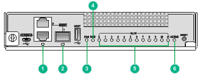
Ports and LEDs
Figure2-7 LSXM1SUP04T2 front panel
|
(1) SFP management Ethernet port LED |
(2) 10/100/1000BASE-T management Ethernet port LED |
|
(3) Fan tray status LED (FAN) |
(4) Power module status LED (PWR) |
|
(5) Module status LEDs (SLOT) |
(6) MPU active/standby status LED (ACTIVE) |
Table2-9 LED description
|
LED |
Status |
Description |
|
Management Ethernet port LED |
Flashing |
The port is in sending or receiving data. |
|
On |
A link is present on the port. |
|
|
Off |
No link is present on the port. |
|
|
Fan tray status LED |
Steady green |
All fan trays are present and operating correctly. |
|
Steady red |
A fan tray is faulty, or no or only one fan tray is operating correctly. |
|
|
Off |
The switch has not been powered on. |
|
|
Power module status LED |
Steady green |
All present power modules are operating correctly. |
|
Steady red |
One or more power modules are faulty. |
|
|
Off |
The switch has not been powered on. |
|
|
Module status LED |
Flashing green (once per two seconds) |
The module is operating correctly. |
|
Flashing green (four times per second) |
The module is loading software. If the LED keeps in this state, the software version running on the switch is not compatible with the module. |
|
|
Steady green |
The module is starting up. |
|
|
Steady red |
A high severity alarm has occurred on the module or the module is faulty. |
|
|
Flashing red (once per four seconds) |
The temperature of the module is abnormal. The temperature has exceeded the upper warning threshold or dropped below the lower warning threshold. |
|
|
Off |
The module is not present or the module is faulty. |
|
|
MPU active/standby status LED |
Steady on |
The MPU is in active state. |
|
Off |
· The MPU is in standby state. · The MPU is faulty. To further determine the MPU status, see the module status LED. |
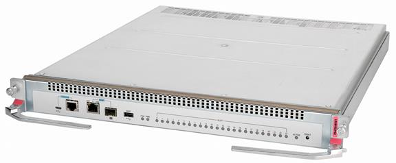
LSXM3SUPS2
View
Figure2-8 LSXM3SUPS2 MPU view
Technical specifications
Table2-10 Technical specifications
|
Item |
Specification |
|
Net weight |
5.60 kg (12.35 lb) |
|
Dimensions (H × W × D) |
44 × 433 × 512 mm (1.73 × 17.05 × 20.16 in) |
|
Power consumption |
· Minimum: 39 W · Typical: 40 W · Maximum: 50 W |
|
Processor |
4 cores, 2.2 GHz |
|
SDRAM |
16 GB |
|
Flash |
2 GB |
|
NVRAM |
1 MB |
|
Connector type |
· RJ-45 · LC · USB (Type A) |
|
Ports |
· 1 × console port · 1 × USB console port · 2 × network management ports (one RJ-45 port and one SFP port) · 1 × USB port |
|
Port transmission speed |
· Console port: 9600 bps (default) to 115200 bps · USB console port: ≤ 115200 bps (default: 9600 bps) · RJ-45 management port: 10/100/1000 Mbps, half/full duplex · SFP management port: 1000 Mbps |
|
Applicable switch models |
All S12500G-AF models |
Ports and LEDs
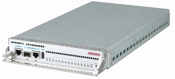
Figure2-9 LSXM3SUPS2 front panel
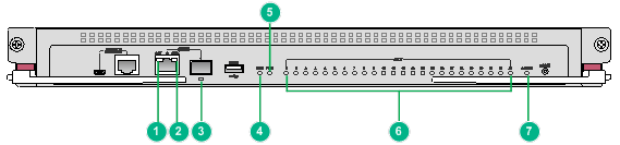
|
(1) 10/100/1000BASE-T management Ethernet port LED (ACT) |
(2) 10/100/1000BASE-T management Ethernet port LED (LINK) |
|
(3) SFP management Ethernet port LED |
(4) Fan tray status LED (FAN) |
|
(5) Power module status LED (PWR) |
(6) Module status LEDs (SLOT) |
|
(7) MPU active/standby status LED (ACTIVE) |
|
Table2-11 LED description
|
LED |
Status |
Description |
|
10/100/1000BASE-T management Ethernet port LEDs |
ACT: Off LINK: Off |
No link is present on the port. |
|
ACT: Off LINK: Steady green |
A 1000 Mbps link is present on the port. |
|
|
ACT: Off LINK: Steady orange |
A 10/100 Mbps link is present on the port. |
|
|
ACT: Flashing yellow LINK: Steady green |
The port is sending or receiving data at 1000 Mbps. |
|
|
ACT: Flashing yellow LINK: Steady orange |
The port is sending or receiving data at 10/100 Mbps. |
|
|
SFP management Ethernet port LED |
Flashing |
The port is in sending or receiving data. |
|
On |
A link is present on the port. |
|
|
Off |
No link is present on the port. |
|
|
Fan tray status LED |
Steady green |
All fan trays are present and operating correctly. |
|
Steady red |
A fan tray is faulty, or no or only one fan tray is operating correctly. |
|
|
Off |
The switch has not been powered on. |
|
|
Power module status LED |
Steady green |
All present power modules are operating correctly. |
|
Steady red |
One or more power modules are faulty. |
|
|
Off |
The switch has not been powered on. |
|
|
Module status LED |
Flashing green (once per two seconds) |
The module is operating correctly. |
|
Flashing green (four times per second) |
The module is loading software. If the LED keeps in this state, the software version running on the switch is not compatible with the module. |
|
|
Steady green |
The module is starting up. |
|
|
Steady red |
A high severity alarm has occurred on the module or the module is faulty. |
|
|
Flashing red (once per four seconds) |
The temperature of the module is abnormal. The temperature has exceeded the upper warning threshold or dropped below the lower warning threshold. |
|
|
Off |
The module is not present or the module is faulty. |
|
|
MPU active/standby status LED |
Steady on |
The MPU is in active state. |
|
Off |
· The MPU is in standby state. · The MPU is faulty. To further determine the MPU status, see the module status LED. |
LSXM1SUPS2
View
Figure2-10 LSXM1SUPS2 MPU view
Technical specifications
Table2-12 Technical specifications
|
Item |
Specification |
|
Net weight |
5.50 kg (12.13 lb) |
|
Dimensions (H × W × D) |
44 × 433 × 512 mm (1.73 × 17.05 × 20.16 in) |
|
Power consumption |
· Minimum: 34 W · Typical: 35 W · Maximum: 40 W |
|
Processor |
Single core, 1 GHz |
|
SDRAM |
2 GB |
|
Flash |
1 GB |
|
NVRAM |
1 MB |
|
Connector type |
· RJ-45 · LC · USB (Type A) |
|
Ports |
· 1 × console port · 1 × USB console port · 2 × network management ports (one RJ-45 port and one SFP port) · 1 × USB port |
|
Port transmission speed |
· Console port: 9600 bps (default) to 115200 bps · USB console port: ≤ 115200 bps (default: 9600 bps) · RJ-45 management port: 10/100/1000 Mbps, half/full duplex · SFP management port: 1000 Mbps |
|
Applicable switch models |
All S12500G-AF models |
Ports and LEDs
Figure2-11 LSXM1SUPS2 front panel
|
(1) 10/100/1000BASE-T management Ethernet port LED (ACT) |
(2) 10/100/1000BASE-T management Ethernet port LED (LINK) |
|
(3) SFP management Ethernet port LED |
(4) Fan tray status LED (FAN) |
|
(5) Power module status LED (PWR) |
(6) Module status LEDs (SLOT) |
|
(7) MPU active/standby status LED (ACTIVE) |
|
Table2-13 LED description
|
LED |
Status |
Description |
|
10/100/1000BASE-T management Ethernet port LEDs |
ACT: Off LINK: Off |
No link is present on the port. |
|
ACT: Off LINK: Steady green |
A 1000 Mbps link is present on the port. |
|
|
ACT: Off LINK: Steady orange |
A 10/100 Mbps link is present on the port. |
|
|
ACT: Flashing yellow LINK: Steady green |
The port is sending or receiving data at 1000 Mbps. |
|
|
ACT: Flashing yellow LINK: Steady orange |
The port is sending or receiving data at 10/100 Mbps. |
|
|
SFP management Ethernet port LED |
Flashing |
The port is in sending or receiving data. |
|
On |
A link is present on the port. |
|
|
Off |
No link is present on the port. |
|
|
Fan tray status LED |
Steady green |
All fan trays are present and operating correctly. |
|
Steady red |
A fan tray is faulty, or no or only one fan tray is operating correctly. |
|
|
Off |
The switch has not been powered on. |
|
|
Power module status LED |
Steady green |
All present power modules are operating correctly. |
|
Steady red |
One or more power modules are faulty. |
|
|
Off |
The switch has not been powered on. |
|
|
Module status LED |
Flashing green (once per two seconds) |
The module is operating correctly. |
|
Flashing green (four times per second) |
The module is loading software. If the LED keeps in this state, the software version running on the switch is not compatible with the module. |
|
|
Steady green |
The module is starting up. |
|
|
Steady red |
A high severity alarm has occurred on the module or the module is faulty. |
|
|
Flashing red (once per four seconds) |
The temperature of the module is abnormal. The temperature has exceeded the upper warning threshold or dropped below the lower warning threshold. |
|
|
Off |
The module is not present or the module is faulty. |
|
|
MPU active/standby status LED |
Steady on |
The MPU is in active state. |
|
Off |
· The MPU is in standby state. · The MPU is faulty. To further determine the MPU status, see the module status LED. |
LSXM3SUP04S2
View
Figure2-12 LSXM3SUP04S2 MPU view
Technical specifications
Table2-14 Technical specifications
|
Item |
Specification |
|
Net weight |
2.75 kg (6.06 lb) |
|
Dimensions (H × W × D) |
40 × 201 × 412 mm (1.57 × 7.91 × 16.22 in) |
|
Power consumption |
· Minimum: 27 W · Typical: 28 W · Maximum: 43 W |
|
Processor |
4 cores, 2.2 GHz |
|
SDRAM |
16 GB |
|
Flash |
2 GB |
|
NVRAM |
1 MB |
|
Connector type |
· RJ-45 · LC · USB (Type A) |
|
Ports |
· 1 × console port · 1 × USB console port · 2 × network management ports (one RJ-45 port and one SFP port) · 1 × USB port |
|
Port transmission speed |
· Console port: 9600 bps (default) to 115200 bps · USB console port: ≤ 115200 bps (default: 9600 bps) · RJ-45 management port: 10/100/1000 Mbps, half/full duplex · SFP management port: 1000 Mbps |
|
Applicable switch models |
S12504G-AF |
Ports and LEDs
Figure2-13 LSXM3SUP04S2 front panel
|
(1) 10/100/1000BASE-T management Ethernet port LED |
(2) SFP management Ethernet port LED |
|
(3) Fan tray status LED (FAN) |
(4) Power module status LED (PWR) |
|
(5) Module status LEDs (SLOT) |
(6) MPU active/standby status LED (ACTIVE) |
Table2-15 LED description
|
LED |
Status |
Description |
|
Management Ethernet port LED |
Flashing |
The port is in sending or receiving data. |
|
On |
A link is present on the port. |
|
|
Off |
No link is present on the port. |
|
|
Fan tray status LED |
Steady green |
All fan trays are present and operating correctly. |
|
Steady red |
A fan tray is faulty, or no or only one fan tray is operating correctly. |
|
|
Off |
The switch has not been powered on. |
|
|
Power module status LED |
Steady green |
All present power modules are operating correctly. |
|
Steady red |
One or more power modules are faulty. |
|
|
Off |
The switch has not been powered on. |
|
|
Module status LED |
Flashing green (once per two seconds) |
The module is operating correctly. |
|
Flashing green (four times per second) |
The module is loading software. If the LED keeps in this state, the software version running on the switch is not compatible with the module. |
|
|
Steady green |
The module is starting up. |
|
|
Steady red |
A high severity alarm has occurred on the module or the module is faulty. |
|
|
Flashing red (once per four seconds) |
The temperature of the module is abnormal. The temperature has exceeded the upper warning threshold or dropped below the lower warning threshold. |
|
|
Off |
The module is not present or the module is faulty. |
|
|
MPU active/standby status LED |
Steady green |
The MPU is in active state. |
|
Off |
· The MPU is in standby state. · The MPU is faulty. To further determine the MPU status, see the module status LED. |
Restrictions and guidelines for service modules
The data drives on the LSXM1SEERBXC2, LSXM1SEERBXD2, LSXM1SEERBG2, LSXM1SEERBA2, or LSXM1SEERBNPA2 module are not hot swappable.
The LSXM1SEERBXC2, LSXM1SEERBXD2, LSXM1SEERBG2, LSXM1SEERBA2, or LSXM1SEERBNPA2 module can be used together only with Type-T MPUs (for example, LSXM2SUPT2) and Type-T fabric modules (for example, LSXM2SFT08E2).
The LSXM1SEERBG2 and LSXM1SEERBA2 modules cannot be used with the LSXM1QGS36TE2 interface module.
Type-S modules include Type-S MPUs (for example, LSXM1SUPS2), Type-S fabric modules (for example, LSXM1SFS08D2), and Type-S service modules (for example, LSXM1TGS48SE2). A Type-S module can be used together only with another Type-S module. You cannot install a Type-S module and a module of another type on the same switch.
Type-T modules include Type-T MPUs (for example, LSXM2SUPT2), Type-T fabric modules (for example, LSXM2SFT08E2), and Type-T service modules (for example, LSXM1TGS48TE2). A Type-T module can be used together only with another Type-T module. You cannot install a Type-T module and a module of another type on the same switch.
SF interface modules (for example, LSXM3TGS48SF2) cannot be used together with Type-S Class-D fabric modules (for example, LSXM1SFS08D).
As a best practice, use SE interface modules (for example, LSXM1TGS48SE2) together with Type-S Class-D fabric modules (for example, LSXM1SFS08D). If you use the LSXM3GP48SE2 or LSXM3GT48SE2 interface module together with other Type-S fabric modules, contact Technical Support to ensure no interface modules on the switch will fail to start up.
400G interface modules
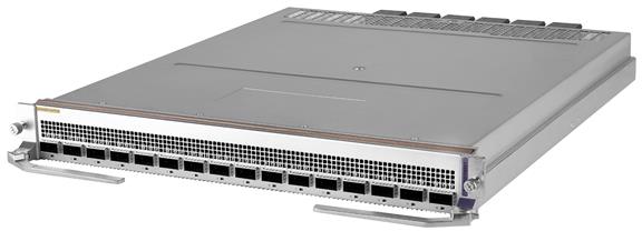
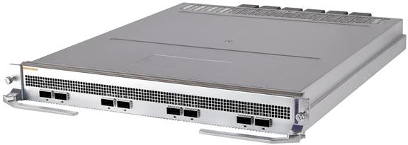
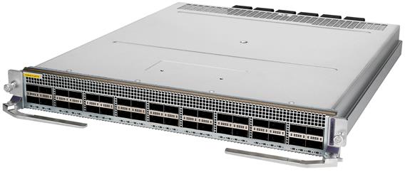
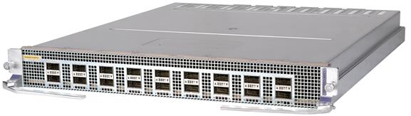
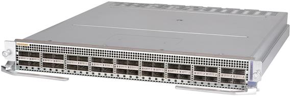
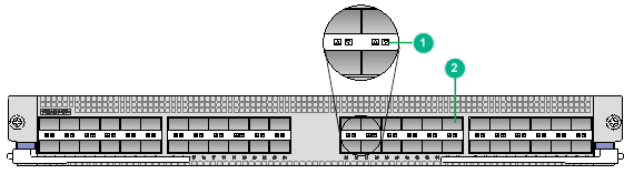
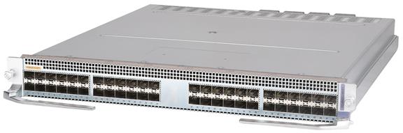
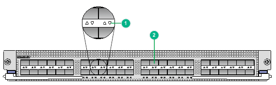
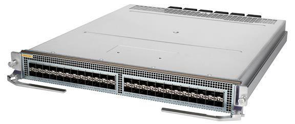
LSXM3CDQ16SF2
View
Figure2-14 LSXM3CDQ16SF2 interface module view
Technical specifications
Table2-16 Technical specifications
|
Item |
Specification |
|
Net weight |
8.85 kg (19.51 lb) |
|
Dimensions (H × W × D) |
50 × 433 × 520 mm (1.97 × 17.05 × 20.47 in) |
|
Power consumption |
· Minimum: 260 W · Typical: 365 W · Maximum: 679 W |
|
Port quantity |
16 |
|
Port type |
400GBASE-R-QSFP-DD fiber port |
|
Available transceiver modules and cables |
· QSFP-DD transceiver modules · QSFP-DD DAC cables · QSFP28 transceiver modules · QSFP28 DAC cables · QSFP28 AOC cables · QSFP+ transceiver modules · QSFP+ DAC cables · QSFP+ AOC cables |
|
Services |
The module provides data access and switching with sixteen 400GE fiber ports |
|
Hot swapping |
Supported |
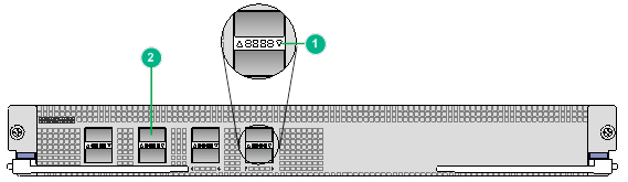
Ports and LEDs
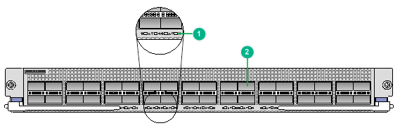
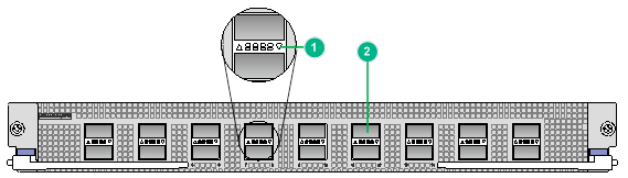
Figure2-15 LSXM3CDQ16SF2 front panel

|
(1) 400GBASE-R-QSFP-DD fiber port LED |
(2) 400GBASE-R-QSFP-DD fiber port |
Table2-17 LED description
|
LED |
Status |
Description |
|
QSFP-DD port LED |
Flashing |
The QSFP-DD port is sending or receiving data. |
|
On |
A link is present on the QSFP-DD port. |
|
|
Off |
No link is present on the QSFP-DD port. |
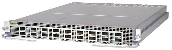
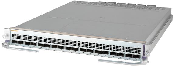
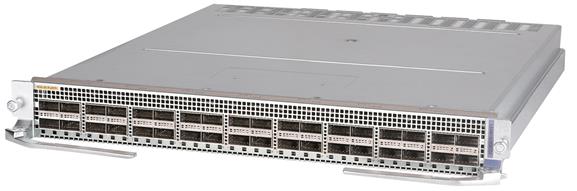
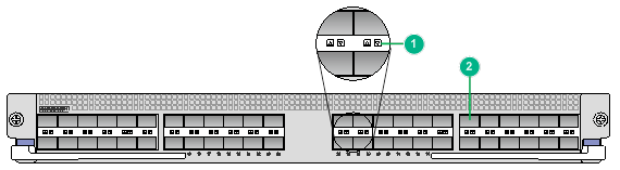
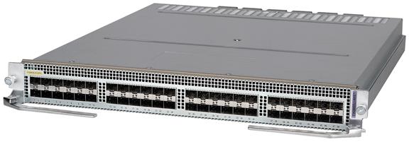
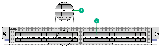
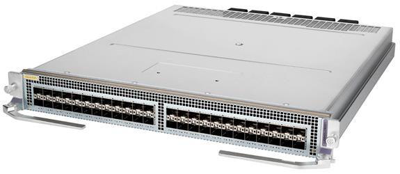
LSXM3CDQ8SF2
View
Figure2-16 LSXM3CDQ8SF2 interface module view
Technical specifications
Table2-18 Technical specifications
|
Item |
Specification |
|
Net weight |
8.50 kg (18.74 lb) |
|
Dimensions (H × W × D) |
50 × 433 × 520 mm (1.97 × 17.05 × 20.47 in) |
|
Power consumption |
· Minimum: 258 W · Typical: 320 W · Maximum: 542 W |
|
Port quantity |
8 |
|
Port type |
400GBASE-R-QSFP-DD fiber port |
|
Available transceiver modules and cables |
· QSFP-DD transceiver modules · QSFP-DD DAC cables · QSFP28 transceiver modules · QSFP28 DAC cables · QSFP28 AOC cables · QSFP+ transceiver modules · QSFP+ DAC cables · QSFP+ AOC cables |
|
Services |
The module provides data access and switching with eight 400GE fiber ports |
|
Hot swapping |
Supported |
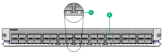
Ports and LEDs
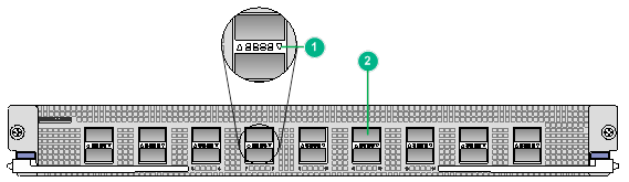
Figure2-17 LSXM3CDQ8SF2 front panel

|
(1) 400GBASE-R-QSFP-DD fiber port LED |
(2) 400GBASE-R-QSFP-DD fiber port |
Table2-19 LED description
|
LED |
Status |
Description |
|
QSFP-DD port LED |
Flashing |
The QSFP-DD port is sending or receiving data. |
|
On |
A link is present on the QSFP-DD port. |
|
|
Off |
No link is present on the QSFP-DD port. |
100G interface modules
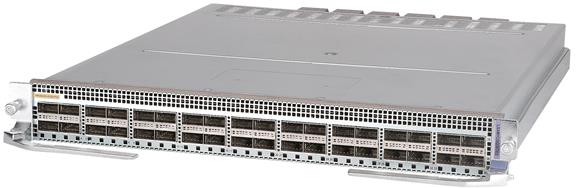
LSXM1CGQ36TE2
View
Figure2-18 LSXM1CGQ36TE2 interface module view
Technical specifications
Table2-20 Technical specifications
|
Item |
Specification |
|
Net weight |
9.20 kg (20.28 lb) |
|
Dimensions (H × W × D) |
50 × 433 × 520 mm (1.97 × 17.05 × 20.47 in) |
|
Power consumption |
· Minimum: 450 W · Typical: 531 W · Maximum: 810 W |
|
Port quantity |
36 |
|
Port type |
100GBASE-R-QSFP28 fiber port |
|
Available transceiver modules and cables |
· QSFP28 transceiver modules · QSFP28 DAC cables · QSFP28 AOC cables · QSFP+ transceiver modules · QSFP+ DAC cables · QSFP+ AOC cables · QSFP28 to SFP28 DAC cables · QSFP+ to SFP+ DAC cables |
|
Services |
The module provides data access and switching with 36 Ethernet fiber ports |
|
Hot swapping |
Supported |
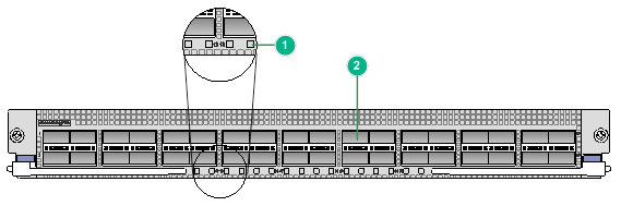
Ports and LEDs
Figure2-19 LSXM1CGQ36TE2 front panel
|
(1) 100GBASE-R-QSFP28 fiber port LED |
(2) 100GBASE-R-QSFP28 fiber port |
Table2-21 LED description
|
LED |
Status |
Description |
|
QSFP28 port LED |
Flashing |
The QSFP28 port is sending or receiving data. |
|
On |
A link is present on the QSFP28 port. |
|
|
Off |
No link is present on the QSFP28 port. |
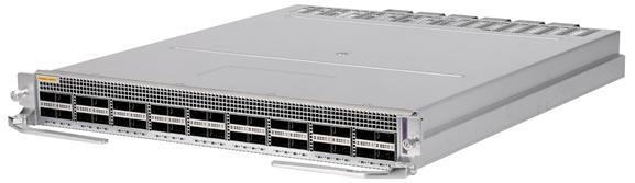
LSXM4CGQ36SF2
View
Figure2-20 LSXM4CGQ36SF2 interface module view
Technical specifications
Table2-22 Technical specifications
|
Item |
Specification |
|
Net weight |
8.95 kg (19.73 lb) |
|
Dimensions (H × W × D) |
50 × 433 × 520 mm (1.97 × 17.05 × 20.47 in) |
|
Power consumption |
· Minimum: 344 W · Typical: 412 W · Maximum: 644 W |
|
Port quantity |
36 |
|
Port type |
100GBASE-R-QSFP28 fiber port |
|
Available transceiver modules and cables |
· QSFP28 transceiver modules · QSFP28 DAC cables · QSFP28 AOC cables · QSFP+ transceiver modules · QSFP+ DAC cables · QSFP+ AOC cables |
|
Services |
The module provides data access and switching with 36 Ethernet fiber ports |
|
Hot swapping |
Supported |
Ports and LEDs
Figure2-21 LSXM4CGQ36SF2 front panel

|
(1) 100GBASE-R-QSFP28 fiber port |
(2) 100GBASE-R-QSFP28 fiber port LED |
Table2-23 LED description
|
LED |
Status |
Description |
|
QSFP28 port LED |
Flashing |
The QSFP28 port is sending or receiving data. |
|
On |
A link is present on the QSFP28 port. |
|
|
Off |
No link is present on the QSFP28 port. |
LSXM3CGQ36SF2
View
Figure2-22 LSXM3CGQ36SF2 interface module view
Technical specifications
Table2-24 Technical specifications
|
Item |
Specification |
|
Net weight |
8.60 kg (18.96 lb) |
|
Dimensions (H × W × D) |
50 × 433 × 520 mm (1.97 × 17.05 × 20.47 in) |
|
Power consumption |
· Minimum: 297 W · Typical: 328 W · Maximum: 587 W |
|
Port quantity |
36 |
|
Port type |
100GBASE-R-QSFP28 fiber port |
|
Available transceiver modules and cables |
· QSFP28 transceiver modules · QSFP28 DAC cables · QSFP28 AOC cables · QSFP+ transceiver modules · QSFP+ DAC cables · QSFP+ AOC cables · QSFP28 to SFP28 DAC cables · QSFP+ to SFP+ DAC cables |
|
Services |
The module provides data access and switching with 36 Ethernet fiber ports |
|
Hot swapping |
Supported |
Ports and LEDs
Figure2-23 LSXM3CGQ36SF2 front panel
|
(1) 100GBASE-R-QSFP28 fiber port LED |
(2) 100GBASE-R-QSFP28 fiber port |
Table2-25 LED description
|
LED |
Status |
Description |
|
QSFP28 port LED |
Flashing |
The QSFP28 port is sending or receiving data. |
|
On |
A link is present on the QSFP28 port. |
|
|
Off |
No link is present on the QSFP28 port. |
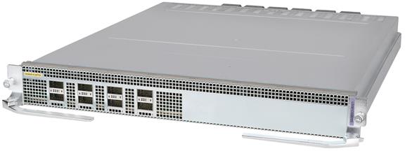
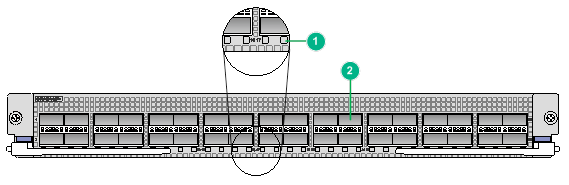
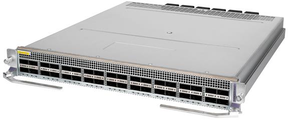
LSXM1CGQ18TE2
View
Figure2-24 LSXM1CGQ18TE2 interface module view
Technical specifications
Table2-26 Technical specifications
|
Item |
Specification |
|
Net weight |
7.70 kg (16.98 lb) |
|
Dimensions (H × W × D) |
50 × 433 × 520 mm (1.97 × 17.05 × 20.47 in) |
|
Power consumption |
· Minimum: 212 W · Typical: 279 W · Maximum: 385 W |
|
Port quantity |
18 |
|
Port type |
100GBASE-R-QSFP28 fiber port |
|
Available transceiver modules and cables |
· QSFP28 transceiver modules · QSFP28 DAC cables · QSFP28 AOC cables · QSFP+ transceiver modules · QSFP+ DAC cables · QSFP+ AOC cables · QSFP28 to SFP28 DAC cables · QSFP+ to SFP+ DAC cables |
|
Services |
The module provides data access and switching with 18 Ethernet fiber ports |
|
Hot swapping |
Supported |
Ports and LEDs
Figure2-25 LSXM1CGQ18TE2 front panel
|
(1) 100GBASE-R-QSFP28 fiber port LED |
(2) 100GBASE-R-QSFP28 fiber port |
Table2-27 LED description
|
LED |
Status |
Description |
|
QSFP28 port LED |
Flashing |
The QSFP28 port is sending or receiving data. |
|
On |
A link is present on the QSFP28 port. |
|
|
Off |
No link is present on the QSFP28 port. |
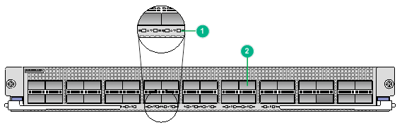
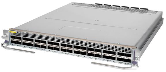
LSXM1CGQ18TD2
View
Figure2-26 LSXM1CGQ18TD2 interface module view
Technical specifications
Table2-28 Technical specifications
|
Item |
Specification |
|
Net weight |
7.90 kg (17.42 lb) |
|
Dimensions (H × W × D) |
50 × 433 × 520 mm (1.97 × 17.05 × 20.47 in) |
|
Power consumption |
· Minimum: 149 W · Typical: 219 W · Maximum: 326 W |
|
Port quantity |
18 |
|
Port type |
100GBASE-R-QSFP28 fiber port |
|
Available transceiver modules and cables |
· QSFP28 transceiver modules · QSFP28 DAC cables · QSFP28 AOC cables · QSFP+ transceiver modules · QSFP+ DAC cables · QSFP+ AOC cables · QSFP28 to SFP28 DAC cables · QSFP+ to SFP+ DAC cables |
|
Services |
The module provides data access and switching with 18 Ethernet fiber ports |
|
Hot swapping |
Supported |
Ports and LEDs
Figure2-27 LSXM1CGQ18TD2 front panel
|
(1) 100GBASE-R-QSFP28 fiber port LED |
(2) 100GBASE-R-QSFP28 fiber port |
Table2-29 LED description
|
LED |
Status |
Description |
|
QSFP28 port LED |
Flashing |
The QSFP28 port is sending or receiving data. |
|
On |
A link is present on the QSFP28 port. |
|
|
Off |
No link is present on the QSFP28 port. |
LSXM3CGQ18SF2
View
Figure2-28 LSXM3CGQ18SF2 interface module view
Technical specifications
Table2-30 Technical specifications
|
Item |
Specification |
|
Net weight |
7.50 kg (16.53 lb) |
|
Dimensions (H × W × D) |
50 × 433 × 520 mm (1.97 × 17.05 × 20.47 in) |
|
Power consumption |
· Minimum: 144 W · Typical: 194 W · Maximum: 311 W |
|
Port quantity |
18 |
|
Port type |
100GBASE-R-QSFP28 fiber port |
|
Available transceiver modules and cables |
· QSFP28 transceiver modules · QSFP28 DAC cables · QSFP28 AOC cables · QSFP+ transceiver modules · QSFP+ DAC cables · QSFP+ AOC cables · QSFP28 to SFP28 DAC cables · QSFP+ to SFP+ DAC cables |
|
Services |
The module provides data access and switching with 18 Ethernet fiber ports |
|
Hot swapping |
Supported |
Ports and LEDs
Figure2-29 LSXM3CGQ18SF2 front panel

|
(1) 100GBASE-R-QSFP28 fiber port LED |
(2) 100GBASE-R-QSFP28 fiber port |
Table2-31 LED description
|
LED |
Status |
Description |
|
QSFP28 port LED |
Flashing |
The QSFP28 port is sending or receiving data. |
|
On |
A link is present on the QSFP28 port. |
|
|
Off |
No link is present on the QSFP28 port. |
LSXM1CGQ8TD2
View
Figure2-30 LSXM1CGQ8TD2 interface module view
Technical specifications
Table2-32 Technical specifications
|
Item |
Specification |
|
Net weight |
7.35 kg (16.20 lb) |
|
Dimensions (H × W × D) |
50 × 433 × 520 mm (1.97 × 17.05 × 20.47 in) |
|
Power consumption |
· Minimum: 85 W · Typical: 117 W · Maximum: 400 W |
|
Port quantity |
8 |
|
Port type |
100GBASE-R-QSFP28 fiber port |
|
Available transceiver modules and cables |
· QSFP28 transceiver modules · QSFP28 DAC cables · QSFP28 AOC cables · QSFP+ transceiver modules · QSFP+ DAC cables · QSFP+ AOC cables · QSFP28 to SFP28 DAC cables · QSFP+ to SFP+ DAC cables |
|
Services |
The module provides data access and switching with eight Ethernet fiber ports |
|
Hot swapping |
Supported |
Ports and LEDs
Figure2-31 LSXM1CGQ8TD2 front panel
|
(1) 100GBASE-R-QSFP28 fiber port LED |
(2) 100GBASE-R-QSFP28 fiber port |
Table2-33 LED description
|
LED |
Status |
Description |
|
QSFP28 port LED |
Flashing |
The QSFP28 port is sending or receiving data. |
|
On |
A link is present on the QSFP28 port. |
|
|
Off |
No link is present on the QSFP28 port. |
40G interface modules
LSXM1QGS36TE2
View
Figure2-32 LSXM1QGS36TE2 interface module view
Technical specifications
Table2-34 Technical specifications
|
Item |
Specification |
|
Net weight |
8.10 kg (17.86 lb) |
|
Dimensions (H × W × D) |
50 × 433 × 520 mm (1.97 × 17.05 × 20.47 in) |
|
Power consumption |
· Minimum: 266 W · Typical: 321 W · Maximum: 510 W |
|
Port quantity |
36 |
|
Port type |
40GBASE-R-QSFP+ fiber port |
|
Available transceiver modules and cables |
· QSFP+ transceiver modules · QSFP+ DAC cables · QSFP+ AOC cables |
|
Services |
The module provides data access and switching with 36 Ethernet fiber ports |
|
Hot swapping |
Supported |
Ports and LEDs
Figure2-33 LSXM1QGS36TE2 front panel
|
(1) 40GBASE-R-QSFP+ fiber port LED |
(2) 40GBASE-R-QSFP+ fiber port |
Table2-35 LED description
|
LED |
Status |
Description |
|
QSFP+ port LED |
Flashing |
The QSFP+ port is sending or receiving data. |
|
On |
A link is present on the QSFP+ port. |
|
|
Off |
No link is present on the QSFP+ port. |
LSXM1QGS36TD2
View
Figure2-34 LSXM1QGS36TD2 interface module view
Technical specifications
Table2-36 Technical specifications
|
Item |
Specification |
|
Net weight |
8.30 kg (18.30 lb) |
|
Dimensions (H × W × D) |
50 × 433 × 520 mm (1.97 × 17.05 × 20.47 in) |
|
Power consumption |
· Minimum: 179 W · Typical: 250 W · Maximum: 400 W |
|
Port quantity |
36 |
|
Port type |
40GBASE-R-QSFP+ fiber port |
|
Available transceiver modules and cables |
· QSFP+ transceiver modules · QSFP+ DAC cables · QSFP+ AOC cables |
|
Services |
The module provides data access and switching with 36 Ethernet fiber ports |
|
Hot swapping |
Supported |
Ports and LEDs
Figure2-35 LSXM1QGS36TD2 front panel
|
(1) 40GBASE-R-QSFP+ fiber port LED |
(2) 40GBASE-R-QSFP+ fiber port |
Table2-37 LED description
|
LED |
Status |
Description |
|
QSFP+ port LED |
Flashing |
The QSFP+ port is sending or receiving data. |
|
On |
A link is present on the QSFP+ port. |
|
|
Off |
No link is present on the QSFP+ port. |
LSXM3QGS36SF2
View
Figure2-36 LSXM3QGS36SF2 interface module view
Technical specifications
Table2-38 Technical specifications
|
Item |
Specification |
|
Net weight |
7.70 kg (16.98 lb) |
|
Dimensions (H × W × D) |
50 × 433 × 520 mm (1.97 × 17.05 × 20.47 in) |
|
Power consumption |
· Minimum: 140 W · Typical: 188 W · Maximum: 356 W |
|
Port quantity |
36 |
|
Port type |
40GBASE-R-QSFP+ fiber port |
|
Available transceiver modules and cables |
· QSFP+ transceiver modules · QSFP+ DAC cables · QSFP+ AOC cables · QSFP+ to SFP+ DAC cables |
|
Services |
The module provides data access and switching with 36 Ethernet fiber ports |
|
Hot swapping |
Supported |
Ports and LEDs
Figure2-37 LSXM3QGS36SF2 front panel
|
(1) 40GBASE-R-QSFP+ fiber port LED |
(2) 40GBASE-R-QSFP+ fiber port |
Table2-39 LED description
|
QSFP+ port |
Status |
Description |
|
Not split |
Flashing |
The QSFP+ port is sending or receiving data. |
|
On |
A link is present on the QSFP+ port. |
|
|
Off |
No link is present on the QSFP+ port. |
|
|
Split into four 10G channels |
Flashing |
A minimum of one channel is receiving or sending data. |
|
On |
A link is present on a minimum of one channel. |
|
|
Off |
No link is present. |
LSXM3QGS36SF1
View
Figure2-38 LSXM3QGS36SF1 interface module view
Technical specifications
Table2-40 Technical specifications
|
Item |
Specification |
|
Net weight |
7.70 kg (16.98 lb) |
|
Dimensions (H × W × D) |
50 × 433 × 520 mm (1.97 × 17.05 × 20.47 in) |
|
Power consumption |
· Minimum: 140 W · Typical: 188 W · Maximum: 356 W |
|
Port quantity |
36 |
|
Port type |
40GBASE-R-QSFP+ fiber port |
|
Available transceiver modules and cables |
· QSFP+ transceiver modules · QSFP+ DAC cables · QSFP+ AOC cables · QSFP+ to SFP+ DAC cables |
|
Services |
The module provides data access and switching with 36 Ethernet fiber ports |
|
Hot swapping |
Supported |
Ports and LEDs
Figure2-39 LSXM3QGS36SF1 front panel
|
(1) 40GBASE-R-QSFP+ fiber port LED |
(2) 40GBASE-R-QSFP+ fiber port |
Table2-41 LED description
|
QSFP+ port |
Status |
Description |
|
Not split |
Flashing |
The QSFP+ port is sending or receiving data. |
|
On |
A link is present on the QSFP+ port. |
|
|
Off |
No link is present on the QSFP+ port. |
|
|
Split into four 10G channels |
Flashing |
A minimum of one channel is receiving or sending data. |
|
On |
A link is present on a minimum of one channel. |
|
|
Off |
No link is present. |
25G interface modules
LSXM3YGS48SF2
View
Figure2-40 LSXM3YGS48SF2 interface module view
Technical specifications
Table2-42 Technical specifications
|
Item |
Specification |
|
Net weight |
7.20 kg (15.87 lb) |
|
Dimensions (H × W × D) |
50 × 433 × 520 mm (1.97 × 17.05 × 20.47 in) |
|
Power consumption |
· Minimum: 101 W · Typical: 118 W · Maximum: 234 W |
|
Port quantity |
48 |
|
Port type |
25GBASE-R-SFP28 fiber port |
|
Available transceiver modules and cables |
· SFP28 transceiver modules · SFP28 DAC cables · SFP28 AOC cables · 10GE SFP+ transceiver modules · 10GE SFP+ DAC cables · GE SFP transceiver modules |
|
Services |
The module provides data access and switching with 48 Ethernet fiber ports |
|
Hot swapping |
Supported |
Ports and LEDs
Figure2-41 LSXM3YGS48SF2 front panel
|
(1) 25GBASE-R-SFP28 fiber port LED |
(2) 25GBASE-R-SFP28 fiber port |
Table2-43 LED description
|
LED |
Status |
Description |
|
SFP28 port LED |
Flashing |
The SFP28 port is sending or receiving data. |
|
On |
A link is present on the SFP28 port. |
|
|
Off |
No link is present on the SFP28 port. |
LSXM1YGS24CGMODTE2
View
Figure2-42 LSXM1YGS24CGMODTE2 interface module view

Technical specifications
Table2-44 Technical specifications
|
Item |
Specification |
|
Net weight |
7.15 kg (15.76 lb) |
|
Dimensions (H × W × D) |
50 × 433 × 520 mm (1.97 × 17.05 × 20.47 in) |
|
Power consumption |
· Minimum: 210 W · Typical: 276 W · Maximum: 483 W |
|
Port quantity |
28 + ports on the interface card |
|
Port type |
· 4 × 100G QSFP28 fiber ports · 24 × 25G SFP28 fiber ports · Ports on the interface card |
|
Available transceiver modules and cables |
· QSFP28 transceiver modules · QSFP28 DAC cables · QSFP28 AOC cables · QSFP+ transceiver modules · QSFP+ DAC cables · QSFP+ AOC cables · SFP28 transceiver modules · SFP28 DAC cables · SFP28 AOC cables |
|
Available interface cards |
· LSWM18QC · LSWM124XG2Q · LSWM124TG2H · LSWM124XGT2Q · LSWM1FWD0 |
|
Services |
The module provides data access and switching with Ethernet fiber ports |
|
Hot swapping |
Supported |
Ports and LEDs
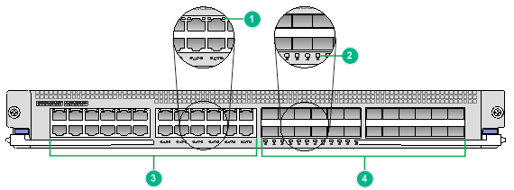
Figure2-43 LSXM1YGS24CGMODTE2 front panel
|
(1) 25GBASE-R-SFP28 fiber port LED |
(2) 100GBASE-R-QSFP28 fiber port LED |
|
(3) 25GBASE-R-SFP28 fiber ports |
(4) 100GBASE-R-QSFP28 fiber ports |
Table2-45 LED description
|
LED |
Status |
Description |
|
SFP28 port LED |
Flashing |
The SFP28 port is sending or receiving data. |
|
On |
A link is present on the SFP28 port. |
|
|
Off |
No link is present on the SFP28 port. |
|
|
QSFP28 port LED |
Flashing |
The QSFP28 port is sending or receiving data. |
|
On |
A link is present on the QSFP28 port. |
|
|
Off |
No link is present on the QSFP28 port. |
10G interface modules
LSXM1TGS48TE2
View
Figure2-44 LSXM1TGS48TE2 interface module view

Technical specifications
Table2-46 Technical specifications
|
Item |
Specification |
|
Net weight |
7.00 kg (15.43 lb) |
|
Dimensions (H × W × D) |
50 × 433 × 520 mm (1.97 × 17.05 × 20.47 in) |
|
Power consumption |
· Minimum: 130 W · Typical: 135 W · Maximum: 220 W |
|
Port quantity |
48 |
|
Port type |
10GBASE-R-SFP+ fiber port |
|
Available transceiver modules and cables |
· 10GE SFP+ transceiver modules · 10GE SFP+ DAC cables · GE SFP transceiver modules |
|
Services |
The module provides data access and switching with 48 Ethernet fiber ports |
|
Hot swapping |
Supported |
Ports and LEDs
Figure2-45 LSXM1TGS48TE2 front panel
|
(1) 10GBASE-R-SFP+ fiber port LED |
(2) 10GBASE-R-SFP+ fiber port |
Table2-47 LED description
|
LED |
Status |
Description |
|
SFP+ port LED |
Flashing |
The SFP+ port is sending or receiving data. |
|
On |
A link is present on the SFP+ port. |
|
|
Off |
No link is present on the SFP+ port. |
LSXM1TGS48TD2
View
Figure2-46 LSXM1TGS48TD2 interface module view
Technical specifications
Table2-48 Technical specifications
|
Item |
Specification |
|
Net weight |
7.00 kg (15.43 lb) |
|
Dimensions (H × W × D) |
50 × 433 × 520 mm (1.97 × 17.05 × 20.47 in) |
|
Power consumption |
· Minimum: 93 W · Typical: 129 W · Maximum: 179 W |
|
Port quantity |
48 |
|
Port type |
10GBASE-R-SFP+ fiber port |
|
Available transceiver modules and cables |
· 10GE SFP+ transceiver modules · 10GE SFP+ DAC cables · GE SFP transceiver modules |
|
Services |
The module provides data access and switching with 48 Ethernet fiber ports |
|
Hot swapping |
Supported |
Ports and LEDs
Figure2-47 LSXM1TGS48TD2 front panel
|
(1) 10GBASE-R-SFP+ fiber port LED |
(2) 10GBASE-R-SFP+ fiber port |
Table2-49 LED description
|
LED |
Status |
Description |
|
SFP+ port LED |
Flashing |
The SFP+ port is sending or receiving data. |
|
On |
A link is present on the SFP+ port. |
|
|
Off |
No link is present on the SFP+ port. |
LSXM1TGS48SE2
View
Figure2-48 LSXM1TGS48SE2 interface module view
Technical specifications
Table2-50 Technical specifications
|
Item |
Specification |
|
Net weight |
7.95 kg (17.53 lb) |
|
Dimensions (H × W × D) |
50 × 433 × 520 mm (1.97 × 17.05 × 20.47 in) |
|
Power consumption |
· Minimum: 143 W · Typical: 158 W · Maximum: 204 W |
|
Port quantity |
48 |
|
Port type |
10GBASE-R-SFP+ fiber port |
|
Available transceiver modules and cables |
· 10GE SFP+ transceiver modules · 10GE SFP+ DAC cables · GE SFP transceiver modules |
|
Services |
The module provides data access and switching with 48 Ethernet fiber ports |
|
Hot swapping |
Supported |
Ports and LEDs
Figure2-49 LSXM1TGS48SE2 front panel
|
(1) 10GBASE-R-SFP+ fiber port LED |
(2) 10GBASE-R-SFP+ fiber port |
Table2-51 LED description
|
LED |
Status |
Description |
|
SFP+ port LED |
Flashing |
The SFP+ port is sending or receiving data. |
|
On |
A link is present on the SFP+ port. |
|
|
Off |
No link is present on the SFP+ port. |
LSXM3TGS48SF2
View
Figure2-50 LSXM3TGS48SF2 interface module view
Technical specifications
Table2-52 Technical specifications
|
Item |
Specification |
|
Net weight |
7.25 kg (15.98 lb) |
|
Dimensions (H × W × D) |
50 × 433 × 520 mm (1.97 × 17.05 × 20.47 in) |
|
Power consumption |
· Minimum: 95 W · Typical: 101 W · Maximum: 175 W |
|
Port quantity |
48 |
|
Port type |
10GBASE-R-SFP+ fiber port |
|
Available transceiver modules and cables |
· 10GE SFP+ transceiver modules · 10GE SFP+ DAC cables · GE SFP transceiver modules |
|
Services |
The module provides data access and switching with 48 Ethernet fiber ports |
|
Hot swapping |
Supported |
Ports and LEDs
Figure2-51 LSXM3TGS48SF2 front panel
|
(1) 10GBASE-R-SFP+ fiber port LED |
(2) 10GBASE-R-SFP+ fiber port |
Table2-53 LED description
|
LED |
Status |
Description |
|
SFP+ port LED |
Flashing |
The SFP+ port is sending or receiving data. |
|
On |
A link is present on the SFP+ port. |
|
|
Off |
No link is present on the SFP+ port. |
LSXM3TGS48SF1
View
Figure2-52 LSXM3TGS48SF1 interface module view
Technical specifications
Table2-54 Technical specifications
|
Item |
Specification |
|
Net weight |
7.25 kg (15.98 lb) |
|
Dimensions (H × W × D) |
50 × 433 × 520 mm (1.97 × 17.05 × 20.47 in) |
|
Power consumption |
· Minimum: 95 W · Typical: 101 W · Maximum: 175 W |
|
Port quantity |
48 |
|
Port type |
10GBASE-R-SFP+ fiber port |
|
Available transceiver modules and cables |
· 10GE SFP+ transceiver modules · 10GE SFP+ DAC cables · GE SFP transceiver modules |
|
Services |
The module provides data access and switching with 48 Ethernet fiber ports |
|
Hot swapping |
Supported |
Ports and LEDs
Figure2-53 LSXM3TGS48SF1 front panel
|
(1) 10GBASE-R-SFP+ fiber port LED |
(2) 10GBASE-R-SFP+ fiber port |
Table2-55 LED description
|
LED |
Status |
Description |
|
SFP+ port LED |
Flashing |
The SFP+ port is sending or receiving data. |
|
On |
A link is present on the SFP+ port. |
|
|
Off |
No link is present on the SFP+ port. |
LSXM3TGT48CQSF2
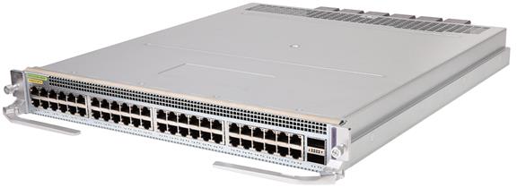
View
Figure2-54 LSXM3TGT48CQSF2 interface module view
Technical specifications
Table2-56 Technical specifications
|
Item |
Specification |
|
Net weight |
7.35 kg (16.20 lb) |
|
Dimensions (H × W × D) |
50 × 433 × 520 mm (1.97 × 17.05 × 20.47 in) |
|
Power consumption |
· Minimum: 154 W · Typical: 190 W · Maximum: 266 W |
|
Port quantity |
50 |
|
Port type |
· 2 × 100GBASE-R-QSFP28 fiber ports · 48 × 10G/5G/2.5G/1G/100BASE-T-RJ45 copper ports |
|
Available transceiver modules and cables |
· QSFP28 transceiver modules · QSFP28 DAC cables · QSFP28 AOC cables · QSFP+ transceiver modules · QSFP+ DAC cables · QSFP+ AOC cables · QSFP28 to SFP28 DAC cables · Category 6A/7 twisted pair cables |
|
Services |
The module provides data access and switching with 2 Ethernet fiber ports and 48 Ethernet copper ports |
|
Hot swapping |
Supported |
Ports and LEDs
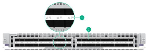
Figure2-55 LSXM3TGT48CQSF2 front panel
|
(1) 10G/5G/2.5G/1G/100BASE-T-RJ45 copper port LED |
(2) 100GBASE-R-QSFP28 fiber port LED |
Table2-57 LED description
|
LED |
Status |
Description |
|
QSFP28 port LED |
Flashing |
The QSFP28 port is sending or receiving data. |
|
On |
A link is present on the QSFP28 port. |
|
|
Off |
No link is present on the QSFP28 port. |
|
|
RJ-45 port LED |
Flashing |
The RJ-45 port is receiving or sending data. |
|
On |
A link is present on the RJ-45 port. |
|
|
Off |
No link is present on the RJ-45 port. |
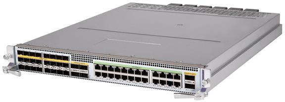
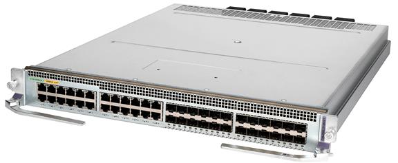
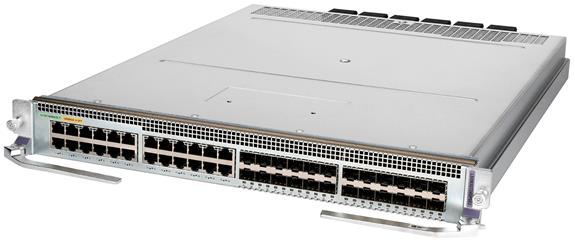
LSXM1TGS24XT24C4Q2TE2
View
Figure2-56 LSXM1TGS24XT24C4Q2TE2 interface module view
Technical specifications
Table2-58 Technical specifications
|
Item |
Specification |
|
Net weight |
8.05 kg (17.75 lb) |
|
Dimensions (H × W × D) |
50 × 433 × 520 mm (1.97 × 17.05 × 20.47 in) |
|
Power consumption |
· Minimum: 193 W · Typical: 246 W · Maximum: 356 W |
|
Port quantity |
54 |
|
Port type |
· 4 × 100GBASE-R-QSFP28 fiber ports · 2 × 40GBASE-R-QSFP+ fiber ports · 24 × 10GBASE-R-SFP+ fiber ports · 24 × 10G/1000BASE-T-RJ45 copper ports |
|
Available transceiver modules and cables |
· QSFP28 transceiver modules · QSFP28 DAC cables · QSFP28 AOC cables · QSFP+ transceiver modules · QSFP+ DAC cables · QSFP+ AOC cables · GE SFP+ transceiver modules · GE SFP+ DAC cables · Category 6A/7 twisted pair cables |
|
Services |
The module provides data access and switching with 30 Ethernet fiber ports and 24 Ethernet copper ports |
|
Hot swapping |
Supported |
Ports and LEDs
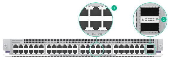
Figure2-57 LSXM1TGS24XT24C4Q2TE2 front panel
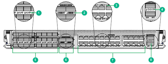
|
(1) 10GBASE-R-SFP+ fiber port LED |
(2) 100GBASE-R-QSFP28 fiber port LED |
|
(3) 10G/1000BASE-T-RJ45 copper port LED |
(4) 40GBASE-R-QSFP+ fiber port LED |
|
(5) 10GBASE-R-SFP+ fiber ports |
(6) 100GBASE-R-QSFP28 fiber ports |
|
(7) 10G/1000BASE-T-RJ45 copper ports |
(8) 40GBASE-R-QSFP+ fiber port |
Table2-59 LED description
|
LED |
Status |
Description |
|
SFP+ port LED |
Flashing |
The SFP+ port is sending or receiving data. |
|
On |
A link is present on the SFP+ port. |
|
|
Off |
No link is present on the SFP+ port. |
|
|
QSFP28 port LED |
Flashing |
The QSFP28 port is sending or receiving data. |
|
On |
A link is present on the QSFP28 port. |
|
|
Off |
No link is present on the QSFP28 port. |
|
|
RJ-45 port LED |
Flashing |
The RJ-45 port is receiving or sending data. |
|
On |
A link is present on the RJ-45 port. |
|
|
Off |
No link is present on the RJ-45 port. |
|
|
QSFP+ port LED |
Flashing |
The QSFP+ port is sending or receiving data. |
|
On |
A link is present on the QSFP+ port. |
|
|
Off |
No link is present on the QSFP+ port. |
|
|
NOTE: You can check the RJ-45 port speed by observing the color of the RJ-45 port LED. Green indicates a speed of 10 Gbps, and yellow indicates a speed of 1 Gbps. |
1G interface modules
LSXM1GT24GPSE2
View
Figure2-58 LSXM1GT24GPSE2 interface module view
Technical specifications
Table2-60 Technical specifications
|
Item |
Specification |
|
Net weight |
7.15 kg (15.76 lb) |
|
Dimensions (H × W × D) |
50 × 433 × 520 mm (1.97 × 17.05 × 20.47 in) |
|
Power consumption |
· Minimum: 64 W · Typical: 75 W · Maximum: 105 W |
|
Port quantity |
48 |
|
Port type |
· 24 × 10/100/1000BASE-T-RJ45 copper ports · 24 × 1000BASE-X-SFP fiber ports |
|
Available transceiver modules and cables |
· GE transceiver modules · Category 5 or above twisted pair cables |
|
Services |
The module provides data access and switching with 24 Ethernet fiber ports and 24 Ethernet copper ports |
|
Hot swapping |
Supported |
Ports and LEDs
Figure2-59 LSXM1GT24GPSE2 front panel

|
(1) 10/100/1000BASE-T-RJ45 copper port LED |
(2) 1000BASE-X-SFP fiber port LED |
|
(3) 10/100/1000BASE-T-RJ45 copper ports |
(4) 1000BASE-X-SFP fiber ports |
Table2-61 LED description
|
LED |
Status |
Description |
|
RJ-45 port LED |
Flashing |
The RJ-45 port is receiving or sending data. |
|
On |
A link is present on the RJ-45 port. |
|
|
Off |
No link is present on the RJ-45 port. |
|
|
SFP port LED |
Flashing |
The SFP port is sending or receiving data. |
|
On |
A link is present on the SFP port. |
|
|
Off |
No link is present on the SFP port. |
|
|
NOTE: · You can check the RJ-45 port speed by observing the color of the RJ-45 port LED. Green indicates a speed of 1000 Mbps, and yellow indicates a speed of 10 or 100 Mbps. · An SFP port operates at 1 Gbps. Its LED is green when the link is connected. |
LSXM3GT24GPSE2
View
Figure2-60 LSXM3GT24GPSE2 interface module view
Technical specifications
Table2-62 Technical specifications
|
Item |
Specification |
|
Net weight |
7.15 kg (15.76 lb) |
|
Dimensions (H × W × D) |
50 × 433 × 520 mm (1.97 × 17.05 × 20.47 in) |
|
Power consumption |
· Minimum: 69 W · Typical: 80 W · Maximum: 97 W |
|
Port quantity |
48 |
|
Port type |
· 24 × 10/100/1000BASE-T-RJ45 copper ports · 24 × 1000BASE-X-SFP fiber ports |
|
Available transceiver modules and cables |
· GE transceiver modules · Category 5 or above twisted pair cables |
|
Services |
The module provides data access and switching with 24 Ethernet fiber ports and 24 Ethernet copper ports |
|
Hot swapping |
Supported |
Ports and LEDs
Figure2-61 LSXM3GT24GPSE2 front panel
|
(1) 10/100/1000BASE-T-RJ45 copper port LED |
(2) 1000BASE-X-SFP fiber port LED |
|
(3) 10/100/1000BASE-T-RJ45 copper ports |
(4) 1000BASE-X-SFP fiber ports |
Table2-63 LED description
|
LED |
Status |
Description |
|
RJ-45 port LED |
Flashing |
The RJ-45 port is receiving or sending data. |
|
On |
A link is present on the RJ-45 port. |
|
|
Off |
No link is present on the RJ-45 port. |
|
|
SFP port LED |
Flashing |
The SFP port is sending or receiving data. |
|
On |
A link is present on the SFP port. |
|
|
Off |
No link is present on the SFP port. |
|
|
NOTE: · You can check the RJ-45 port speed by observing the color of the RJ-45 port LED. Green indicates a speed of 1000 Mbps, and yellow indicates a speed of 10 or 100 Mbps. · An SFP port operates at 1 Gbps. Its LED is green when the link is connected. |
LSXM1GT48SE2
View
Figure2-62 LSXM1GT48SE2 interface module view
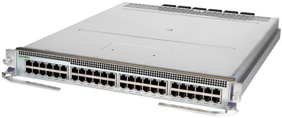
Technical specifications
Table2-64 Technical specifications
|
Item |
Specification |
|
Net weight |
7.10 kg (15.65 lb) |
|
Dimensions (H × W × D) |
50 × 433 × 520 mm (1.97 × 17.05 × 20.47 in) |
|
Power consumption |
· Minimum: 65 W · Typical: 75 W · Maximum: 90 W |
|
Port quantity |
48 |
|
Port type |
10/100/1000BASE-T-RJ45 copper ports |
|
Available transceiver modules and cables |
Category 5 or above twisted pair cables |
|
Services |
The module provides data access and switching with 48 Ethernet copper ports |
|
Hot swapping |
Supported |
Ports and LEDs
Figure2-63 LSXM1GT48SE2 front panel
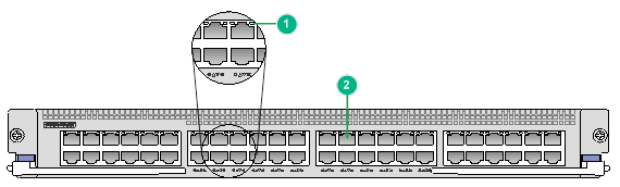
|
(1) 10/100/1000BASE-T-RJ45 copper port LED |
(2) 10/100/1000BASE-T-RJ45 copper port |
Table2-65 LED description
|
LED |
Status |
Description |
|
RJ-45 port LED |
Flashing |
The RJ-45 port is receiving or sending data. |
|
On |
A link is present on the RJ-45 port. |
|
|
Off |
No link is present on the RJ-45 port. |
|
|
NOTE: You can check the RJ-45 port speed by observing the color of the RJ-45 port LED. Green indicates a speed of 1000 Mbps, and yellow indicates a speed of 10 or 100 Mbps. |
LSXM3GT48SE2
View
Figure2-64 LSXM3GT48SE2 interface module view

Technical specifications
Table2-66 Technical specifications
|
Item |
Specification |
|
Net weight |
7.10 kg (15.65 lb) |
|
Dimensions (H × W × D) |
50 × 433 × 520 mm (1.97 × 17.05 × 20.47 in) |
|
Power consumption |
· Minimum: 70 W · Typical: 80 W · Maximum: 96 W |
|
Port quantity |
48 |
|
Port type |
10/100/1000BASE-T-RJ45 copper ports |
|
Available transceiver modules and cables |
Category 5 or above twisted pair cables |
|
Services |
The module provides data access and switching with 48 Ethernet copper ports |
|
Hot swapping |
Supported |
Ports and LEDs
Figure2-65 LSXM3GT48SE2 front panel
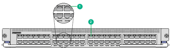
|
(1) 10/100/1000BASE-T-RJ45 copper port LED |
(2) 10/100/1000BASE-T-RJ45 copper port |
Table2-67 LED description
|
LED |
Status |
Description |
|
RJ-45 port LED |
Flashing |
The RJ-45 port is receiving or sending data. |
|
On |
A link is present on the RJ-45 port. |
|
|
Off |
No link is present on the RJ-45 port. |
|
|
NOTE: You can check the RJ-45 port speed by observing the color of the RJ-45 port LED. Green indicates a speed of 1000 Mbps, and yellow indicates a speed of 10 or 100 Mbps. |
LSXM3GP48SE2
View
Figure2-66 LSXM3GP48SE2 interface module view
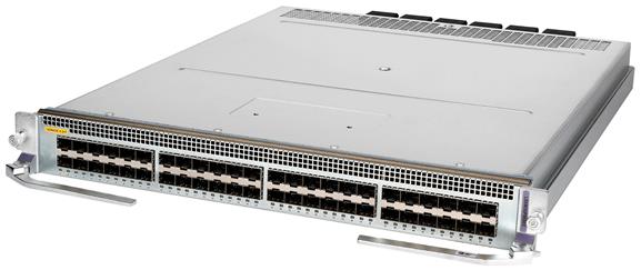
Technical specifications
Table2-68 Technical specifications
|
Item |
Specification |
|
Net weight |
7.15 kg (15.76 lb) |
|
Dimensions (H × W × D) |
50 × 433 × 520 mm (1.97 × 17.05 × 20.47 in) |
|
Power consumption |
· Minimum: 61 W · Typical: 71 W · Maximum: 89 W |
|
Port quantity |
48 |
|
Port type |
1000BASE-X-SFP fiber ports |
|
Available transceiver modules and cables |
GE SFP transceiver modules |
|
Services |
The module provides data access and switching with Ethernet fiber ports |
|
Hot swapping |
Supported |
Ports and LEDs
Figure2-67 LSXM3GP48SE2 front panel
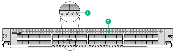
|
(1) 1000BASE-X-SFP fiber port LED |
(2) 1000BASE-X-SFP fiber port |
Table2-69 LED description
|
LED |
Status |
Description |
|
SFP port LED |
Flashing |
The SFP port is sending or receiving data. |
|
On |
A link is present on the SFP port. |
|
|
Off |
No link is present on the SFP port. |
Integrated service modules
LSXM1SEERBXC2
View
Figure2-68 LSXM1SEERBXC2 integrated service module view
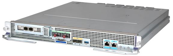
Technical specifications
Table2-70 Technical specifications
|
Item |
Specification |
|
Description |
Campus SeerEngine module |
|
Net weight |
8.90 kg (19.62 lb) |
|
Dimensions (H × W × D) |
50 × 433 × 520 mm (1.97 × 17.05 × 20.47 in) |
|
Power consumption |
· Minimum: 140 W · Typical: 245 W · Maximum: 285 W |
|
Port quantity |
10 |
|
Port type |
· 3 × 10GBASE-R-SFP+ fiber ports · 1 × 10GBASE-R-SFP+ HDM shared network port (used for Ethernet connection or HDM access) · 2 × 1 TB data drive ports · 1 × SUV port (using an SUV connector) · 1 × USB 3.0 port · 1 × console port (used by technical support for debugging only) · 1 × 10/100/1000BASE-T HDM dedicated network port (default IP address: 192.168.1.2/24) NOTE: The HDM shared network port obtains an IP address through DHCP automatically. |
|
Services |
The LSXM1SEERBXC2 is preinstalled with Application-Driven Campus (AD-Campus) solution components such as U-Center, endpoint intelligent access (EIA), vDHCP, and SeerEngine. It supports plug and play and policy enforcement as users move around, and can be automatically deployed on small and medium-sized campus networks, eliminating the need to install physical servers. |
|
Hot swapping |
Supported |
Ports and LEDs
Figure2-69 LSXM1SEERBXC2 front panel
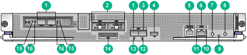
|
(1) SFP+ fiber ports (3 in total) |
(2) Data drive ports (SSD0 and SSD1) |
|
(3) HDM shared network port |
(4) USB 3.0 port |
|
(5) Console port |
(6) HDM dedicated network port |
|
(7) UID button/LED |
(8) Power on/standby button and system power LED |
|
(9) Health LED |
(10) HDM dedicated network port LED (ACT) |
|
(11) HDM dedicated network port LED (LINK) |
(12) HDM shared network port LED |
|
(13) SFP+ fiber port LED |
(14) SUV port (using an SUV connector) |
|
(15) SFP+ fiber port LEDs (ACT) |
(16) SFP+ fiber port LEDs (LINK) |
Table2-71 LED description
|
LED |
Status |
Description |
|
SFP+ fiber port LEDs (LINK and ACT) |
LINK: Steady on ACT: Flashing |
A link is present on the port and the port is sending or receiving data. |
|
LINK: Steady on ACT: Off |
A link is present on the port but the port is not sending or receiving data. |
|
|
LINK: Off ACT: Off |
No link is present on the port. |
|
|
System power LED |
Steady green |
The system has started up. |
|
Flashing |
The system is starting up. |
|
|
Steady amber |
The system is in standby state. |
|
|
Off |
No power input. |
|
|
Health LED |
Steady green |
The system is operating correctly. |
|
Flashing green |
HDM is being initialized. |
|
|
Flashing amber (0.5 Hz) |
A predictive alarm has occurred. |
|
|
Flashing amber (1 Hz) |
A general alarm has occurred. |
|
|
Flashing red |
A severe alarm has occurred. |
|
|
Off |
The system is not powered on or the module is not installed correctly. |
|
|
UID button/LED |
Steady on |
The UID LED is activated. The UID LED can be activated by pressing the UID button or from HDM or OM. |
|
Flashing (1 Hz) |
The system is being managed from HDM or the firmware is being upgraded. |
|
|
Flashing (4 Hz) |
HDM is restarting. To restart HDM, press the UID button/LED for 8 seconds. |
|
|
Off |
The UID LED is not activated. |
|
|
HDM dedicated network port LEDs (LINK and ACT) |
LINK: Steady on ACT: Flashing |
A link is present on the port and the port is sending or receiving data. |
|
LINK: Steady on ACT: Off |
A link is present on the port. |
|
|
LINK: Off ACT: Off |
No link is present on the port. |
|
|
SFP+ fiber port/HDM shared network port LED |
Steady on |
A link is present on the port. |
|
Flashing |
The port is sending or receiving data. |
|
|
Off |
No link is present on the port. |
LSXM1SEERBXD2
View
Figure2-70 LSXM1SEERBXD2 integrated service module view
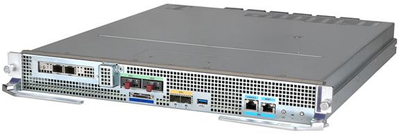
Technical specifications
Table2-72 Technical specifications
|
Item |
Specification |
|
Description |
DC SeerEngine module |
|
Net weight |
8.90 kg (19.62 lb) |
|
Dimensions (H × W × D) |
50 × 433 × 520 mm (1.97 × 17.05 × 20.47 in) |
|
Power consumption |
· Minimum: 140 W · Typical: 245 W · Maximum: 285 W |
|
Port quantity |
10 |
|
Port type |
· 3 × 10GBASE-R-SFP+ fiber ports · 1 × 10GBASE-R-SFP+ HDM shared network port (used for Ethernet connection or HDM access) · 2 × 1 TB data drive ports · 1 × SUV port (using an SUV connector) · 1 × USB 3.0 port · 1 × console port (used by technical support for debugging only) · 1 × 10/100/1000BASE-T HDM dedicated network port (default IP address: 192.168.1.2/24) NOTE: The HDM shared network port obtains an IP address through DHCP automatically. |
|
Services |
The LSXM1SEERBXD2 is preinstalled with Application-Driven Data Center (AD-DC) solution components such as SeerNetwork Architecture (SNA) Center and SeerEngine. It can be used to build a stateless network for small and medium-sized data centers. It enables pooling of all computing, network, and security resources and provides complete virtual data center (vDC) capabilities, eliminating the need to install physical servers. |
|
Hot swapping |
Supported |
Ports and LEDs
Figure2-71 LSXM1SEERBXD2 front panel

|
(1) SFP+ fiber ports (3 in total) |
(2) Data drive ports (SSD0 and SSD1) |
|
(3) HDM shared network port |
(4) USB 3.0 port |
|
(5) Console port |
(6) HDM dedicated network port |
|
(7) UID button/LED |
(8) Power on/standby button and system power LED |
|
(9) Health LED |
(10) HDM dedicated network port LED (ACT) |
|
(11) HDM dedicated network port LED (LINK) |
(12) HDM shared network port LED |
|
(13) SFP+ fiber port LED |
(14) SUV port (using an SUV connector) |
|
(15) SFP+ fiber port LEDs (ACT) |
(16) SFP+ fiber port LEDs (LINK) |
Table2-73 LED description
|
LED |
Status |
Description |
|
SFP+ fiber port LEDs (LINK and ACT) |
LINK: Steady on ACT: Flashing |
A link is present on the port and the port is sending or receiving data. |
|
LINK: Steady on ACT: Off |
A link is present on the port but the port is not sending or receiving data. |
|
|
LINK: Off ACT: Off |
No link is present on the port. |
|
|
System power LED |
Steady green |
The system has started up. |
|
Flashing |
The system is starting up. |
|
|
Steady amber |
The system is in standby state. |
|
|
Off |
No power input. |
|
|
Health LED |
Steady green |
The system is operating correctly. |
|
Flashing green |
HDM is being initialized. |
|
|
Flashing amber (0.5 Hz) |
A predictive alarm has occurred. |
|
|
Flashing amber (1 Hz) |
A general alarm has occurred. |
|
|
Flashing red |
A severe alarm has occurred. |
|
|
Off |
The system is not powered on or the module is not installed correctly. |
|
|
UID button/LED |
Steady on |
The UID LED is activated. The UID LED can be activated by pressing the UID button or from HDM or OM. |
|
Flashing (1 Hz) |
The system is being managed from HDM or the firmware is being upgraded. |
|
|
Flashing (4 Hz) |
HDM is restarting. To restart HDM, press the UID button/LED for 8 seconds. |
|
|
Off |
The UID LED is not activated. |
|
|
HDM dedicated network port LEDs (LINK and ACT) |
LINK: Steady on ACT: Flashing |
A link is present on the port and the port is sending or receiving data. |
|
LINK: Steady on ACT: Off |
A link is present on the port. |
|
|
LINK: Off ACT: Off |
No link is present on the port. |
|
|
SFP+ fiber port/HDM shared network port LED |
Steady on |
A link is present on the port. |
|
Flashing |
The port is sending or receiving data. |
|
|
Off |
No link is present on the port. |
LSXM1SEERBA2
View
Figure2-72 LSXM1SEERBA2 integrated service module view
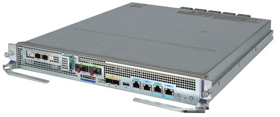
Technical specifications
Table2-74 Technical specifications
|
Item |
Specification |
|
Description |
High performance compute engine module |
|
Net weight |
9.50 kg (20.94 lb) |
|
Dimensions (H × W × D) |
50 × 433 × 520 mm (1.97 × 17.05 × 20.47 in) |
|
Power consumption |
· Minimum: 170 W · Typical: 295 W · Maximum: 385 W |
|
Port quantity |
12 |
|
Port type |
· 3 × 10GBASE-R-SFP+ fiber ports · 1 × 10GBASE-R-SFP+ HDM shared network port (used for Ethernet connection or HDM access) · 2 × 1 TB data drive ports · 1 × SUV port (using an SUV connector) · 1 × USB 3.0 port · 2 × console ports (used by technical support for debugging only) · 1 × 10/100/1000BASE-T management Ethernet port (used by technical support for debugging only) · 1 × 10/100/1000BASE-T HDM dedicated network port (default IP address: 192.168.1.2/24) NOTE: The HDM shared network port obtains an IP address through DHCP automatically. |
|
Services |
The LSXM1SEERBA2 is preinstalled with a Linux operating system. It is a high performance computing platform that is deeply converged with networking features and provides high-performance CPUs as well as a large storage space. The module can meet the requirements of small to medium-sized enterprises for lightweight deployment of big data applications. |
|
Hot swapping |
Supported |
Ports and LEDs
Figure2-73 LSXM1SEERBA2 front panel
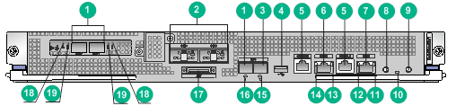
|
(1) SFP+ fiber ports (3 in total) |
(2) Data drive ports (SSD0 and SSD1) |
|
(3) HDM shared network port |
(4) USB 3.0 port |
|
(5) Console port |
(6) Management Ethernet port |
|
(7) HDM dedicated network port |
(8) UID button/LED |
|
(9) Power on/standby button and system power LED |
(10) Health LED |
|
(11) HDM dedicated network port LED (ACT) |
(12) HDM dedicated network port LED (LINK) |
|
(13) Management Ethernet port LED (ACT) |
(14) Management Ethernet port LED (LINK) |
|
(15) HDM shared network port LED |
(16) SFP+ fiber port LED |
|
(17) SUV port (using an SUV connector) |
(18) SFP+ fiber port LEDs (ACT) |
|
(19) SFP+ fiber port LEDs (LINK) |
|
Table2-75 LED description
|
LED |
Status |
Description |
|
SFP+ fiber port LEDs (LINK and ACT) |
LINK: Steady on ACT: Flashing |
A link is present on the port and the port is sending or receiving data. |
|
LINK: Steady on ACT: Off |
A link is present on the port but the port is not sending or receiving data. |
|
|
LINK: Off ACT: Off |
No link is present on the port. |
|
|
System power LED |
Steady green |
The system has started up. |
|
Flashing |
The system is starting up. |
|
|
Steady amber |
The system is in standby state. |
|
|
Off |
No power input. |
|
|
Health LED |
Steady green |
The system is operating correctly. |
|
Flashing green |
HDM is being initialized. |
|
|
Flashing amber (0.5 Hz) |
A predictive alarm has occurred. |
|
|
Flashing amber (1 Hz) |
A general alarm has occurred. |
|
|
Flashing red |
A severe alarm has occurred. |
|
|
Off |
The system is not powered on or the module is not installed correctly. |
|
|
UID button/LED |
Steady on |
The UID LED is activated. The UID LED can be activated by pressing the UID button or from HDM or OM. |
|
Flashing (1 Hz) |
The system is being managed from HDM or the firmware is being upgraded. |
|
|
Flashing (4 Hz) |
HDM is restarting. To restart HDM, press the UID button/LED for 8 seconds. |
|
|
Off |
The UID LED is not activated. |
|
|
Management Ethernet port/HDM dedicated network port LEDs (LINK and ACT) |
LINK: Steady on ACT: Flashing |
A link is present on the port and the port is sending or receiving data. |
|
LINK: Steady on ACT: Off |
A link is present on the port. |
|
|
LINK: Off ACT: Off |
No link is present on the port. |
|
|
SFP+ fiber port/HDM shared network port LED |
Steady on |
A link is present on the port. |
|
Flashing |
The port is sending or receiving data. |
|
|
Off |
No link is present on the port. |
LSXM1SEERBG2
View
Figure2-74 LSXM1SEERBG2 integrated service module view
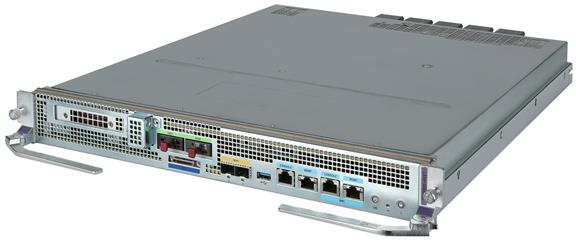
Technical specifications
Table2-76 Technical specifications
|
Item |
Specification |
|
Description |
AI compute engine module |
|
Net weight |
11.40 kg (25.13 lb) |
|
Dimensions (H × W × D) |
50 × 433 × 520 mm (1.97 × 17.05 × 20.47 in) |
|
Power consumption |
· Minimum: 267 W · Typical: 453 W · Maximum: 615 W |
|
Port quantity |
10 |
|
Port type |
· 1 × 10GBASE-R SFP+ fiber port · 1 × 10GBASE-R SFP+ HDM shared network port (used for Ethernet connection or HDM access) · 2 × 1 TB data drive ports · 1 × SUV port (using an SUV connector) · 1 × USB 3.0 port · 2 × console ports (used by technical support for debugging only) · 1 × 10/100/1000BASE-T management Ethernet port (used by technical support for debugging only) · 1 × 10/100/1000BASE-T HDM dedicated network port (default IP address: 192.168.1.2/24) NOTE: The HDM shared network port obtains an IP address through DHCP automatically. |
|
Services |
The LSXM1SEERBG2 is preinstalled with a Linux operating system. It is an intelligent computing platform that is deeply converged with networking features and provides high-performance CPUs and GPUs as well as a large storage space. The module can meet the requirements of small to medium-sized enterprises for lightweight deployment of AI+big data applications. |
|
Hot swapping |
Supported |
Ports and LEDs
Figure2-75 LSXM1SEERBG2 front panel
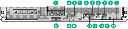
|
(1) Data drive ports (SSD0 and SSD1) |
(2) SFP+ fiber port |
|
(3) HDM shared network port |
(4) USB 3.0 port |
|
(5) Console port |
(6) Management Ethernet port |
|
(7) HDM dedicated network port |
(8) UID button/LED |
|
(9) Power on/standby button and system power LED |
(10) Health LED |
|
(11) HDM dedicated network port LED (ACT) |
(12) HDM dedicated network port LED (LINK) |
|
(13) Management Ethernet port LED (ACT) |
(14) Management Ethernet port LED (LINK) |
|
(15) HDM shared network port LED |
(16) SFP+ fiber port LED |
|
(17) SUV port (using an SUV connector) |
|
Table2-77 LED description
|
LED |
Status |
Description |
|
System power LED |
Steady green |
The system has started up. |
|
Flashing |
The system is starting up. |
|
|
Steady amber |
The system is in standby state. |
|
|
Off |
No power input. |
|
|
Health LED |
Steady green |
The system is operating correctly. |
|
Flashing green |
HDM is being initialized. |
|
|
Flashing amber (0.5 Hz) |
A predictive alarm has occurred. |
|
|
Flashing amber (1 Hz) |
A general alarm has occurred. |
|
|
Flashing red |
A severe alarm has occurred. |
|
|
Off |
The system is not powered on or the module is not installed correctly. |
|
|
UID button/LED |
Steady on |
The UID LED is activated. The UID LED can be activated by pressing the UID button or from HDM or OM. |
|
Flashing (1 Hz) |
The system is being managed from HDM or the firmware is being upgraded. |
|
|
Flashing (4 Hz) |
HDM is restarting. To restart HDM, press the UID button/LED for 8 seconds. |
|
|
Off |
The UID LED is not activated. |
|
|
Management Ethernet port/HDM dedicated network port LEDs (LINK and ACT) |
LINK: Steady on ACT: Flashing |
A link is present on the port and the port is sending or receiving data. |
|
LINK: Steady on ACT: Off |
A link is present on the port. |
|
|
LINK: Off ACT: Off |
No link is present on the port. |
|
|
SFP+ fiber port/HDM shared network port LED |
Steady on |
A link is present on the port. |
|
Flashing |
The port is sending or receiving data. |
|
|
Off |
No link is present on the port. |
LSXM1SEERBNPA2
View
Figure2-76 LSXM1SEERBNPA2 integrated service module view
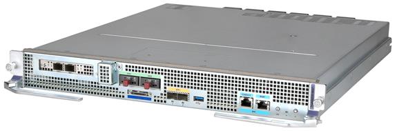
Technical specifications
Table2-78 Technical specifications
|
Item |
Specification |
|
Description |
Network performance analytics module |
|
Net weight |
8.90 kg (19.62 lb) |
|
Dimensions (H × W × D) |
50 × 433 × 520 mm (1.97 × 17.05 × 20.47 in) |
|
Power consumption |
· Minimum: 140 W · Typical: 245 W · Maximum: 285 W |
|
Port quantity |
10 |
|
Port type |
· 3 × 10GBASE-R-SFP+ fiber ports · 1 × 10GBASE-R-SFP+ HDM shared network port (used for Ethernet connection or HDM access) · 2 × 1 TB data drive ports · 1 × SUV port (using an SUV connector) · 1 × USB 3.0 port · 1 × console port (used by technical support for debugging only) · 1 × 10/100/1000BASE-T HDM dedicated network port (default IP address: 192.168.1.2/24) NOTE: The HDM shared network port obtains an IP address through DHCP automatically. |
|
Services |
The LSXM1SEERBNPA2 is provided with high-capacity storage. By collecting and analyzing network traffic, it can fast locate faults in the network, providing assurance for key services and enhancing network issue processing efficiency. |
|
Hot swapping |
Supported |
Ports and LEDs
Figure2-77 LSXM1SEERBNPA2 front panel
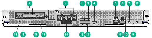
|
(1) SFP+ fiber ports (3 in total) |
(2) Data drive ports (SSD0 and SSD1) |
|
(3) HDM shared network port |
(4) USB 3.0 port |
|
(5) Console port |
(6) HDM dedicated network port |
|
(7) UID button/LED |
(8) Power on/standby button and system power LED |
|
(9) Health LED |
(10) HDM dedicated network port LED (ACT) |
|
(11) HDM dedicated network port LED (LINK) |
(12) HDM shared network port LED |
|
(13) SFP+ fiber port LED |
(14) SUV port (using an SUV connector) |
|
(15) SFP+ fiber port LEDs (ACT) |
(16) SFP+ fiber port LEDs (LINK) |
Table2-79 LED description
|
LED |
Status |
Description |
|
SFP+ fiber port LEDs (LINK and ACT) |
LINK: Steady on ACT: Flashing |
A link is present on the port and the port is sending or receiving data. |
|
LINK: Steady on ACT: Off |
A link is present on the port but the port is not sending or receiving data. |
|
|
LINK: Off ACT: Off |
No link is present on the port. |
|
|
System power LED |
Steady green |
The system has started up. |
|
Flashing |
The system is starting up. |
|
|
Steady amber |
The system is in standby state. |
|
|
Off |
No power input. |
|
|
Health LED |
Steady green |
The system is operating correctly. |
|
Flashing green |
HDM is being initialized. |
|
|
Flashing amber (0.5 Hz) |
A predictive alarm has occurred. |
|
|
Flashing amber (1 Hz) |
A general alarm has occurred. |
|
|
Flashing red |
A severe alarm has occurred. |
|
|
Off |
The system is not powered on or the module is not installed correctly. |
|
|
UID button/LED |
Steady on |
The UID LED is activated. The UID LED can be activated by pressing the UID button or from HDM or OM. |
|
Flashing (1 Hz) |
The system is being managed from HDM or the firmware is being upgraded. |
|
|
Flashing (4 Hz) |
HDM is restarting. To restart HDM, press the UID button/LED for 8 seconds. |
|
|
Off |
The UID LED is not activated. |
|
|
HDM dedicated network port LEDs (LINK and ACT) |
LINK: Steady on ACT: Flashing |
A link is present on the port and the port is sending or receiving data. |
|
LINK: Steady on ACT: Off |
A link is present on the port. |
|
|
LINK: Off ACT: Off |
No link is present on the port. |
|
|
SFP+ fiber port/HDM shared network port LED |
Steady on |
A link is present on the port. |
|
Flashing |
The port is sending or receiving data. |
|
|
Off |
No link is present on the port. |
Interface cards
|
|
CAUTION: Before hot swapping an interface card, make sure the switch is operating correctly. Do not install or remove an interface card during startup of the switch. |
LSWM18QC
View
Figure2-78 LSWM18QC interface card view
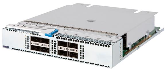
Technical specifications
Table2-80 Technical specifications
|
Item |
Specification |
|
Net weight |
2.00 kg (4.41 lb) |
|
Dimensions (H × W × D) |
40.1 × 214 × 274 mm (1.58 × 8.43 × 10.79 in) |
|
Power consumption |
· Minimum: 15 W · Typical: 22 W · Maximum: 30 W |
|
Port quantity |
8 |
|
Port type |
40GBASE-R-QSFP+ fiber ports |
|
Available transceiver modules and cables |
· QSFP+ transceiver modules · QSFP+ DAC cables · QSFP+ AOC cables |
|
Services |
The module provides data access and switching with eight Ethernet fiber ports |
|
Hot swapping |
Supported |
Ports and LEDs
Figure2-79 LSWM18QC front panel
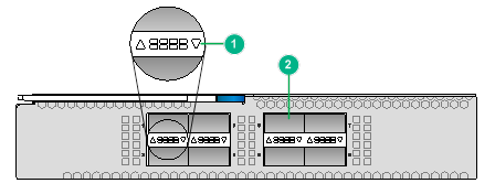
|
(1) 40GBASE-R-QSFP+ fiber port LED |
(2) 40GBASE-R-QSFP+ fiber port |
Table2-81 LED description
|
LED |
Status |
Description |
|
QSFP+ port LED |
Flashing |
The QSFP+ port is sending or receiving data. |
|
On |
A link is present on the QSFP+ port. |
|
|
Off |
No link is present on the QSFP+ port. |
LSWM124XG2Q
View
Figure2-80 LSWM124XG2Q interface card view
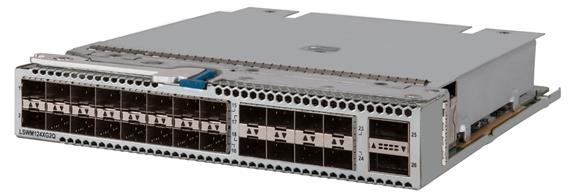
Technical specifications
Table2-82 Technical specifications
|
Item |
Specification |
|
Net weight |
2.00 kg (4.41 lb) |
|
Dimensions (H × W × D) |
40.1 × 214 × 274 mm (1.58 × 8.43 × 10.79 in) |
|
Power consumption |
· Minimum: 40 W · Typical: 50 W · Maximum: 60 W |
|
Port quantity |
26 |
|
Port type |
· 2 × 40GBASE-R-QSFP+ fiber ports · 24 × 10GBASE-R-SFP+ fiber ports |
|
Available transceiver modules and cables |
· QSFP+ transceiver modules · QSFP+ DAC cables · QSFP+ AOC cables · 10GE SFP+ transceiver modules · 10GE SFP+ DAC cables · GE SFP transceiver modules |
|
Services |
The module provides data access and switching with 26 Ethernet fiber ports |
|
Hot swapping |
Supported |
Ports and LEDs
Figure2-81 LSWM124XG2Q front panel
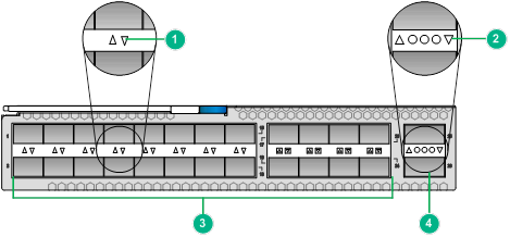
|
(1) 10GBASE-R-SFP+ fiber port LED |
(2) 40GBASE-R-QSFP+ fiber port LED |
|
(3) 10GBASE-R-SFP+ fiber ports |
(4) 40GBASE-R-QSFP+ fiber port |
Table2-83 LED description
|
LED |
Status |
Description |
|
SFP+ port LED |
Flashing |
The SFP+ port is sending or receiving data. |
|
On |
A link is present on the SFP+ port. |
|
|
Off |
No link is present on the SFP+ port. |
|
|
QSFP+ port LED |
Flashing |
The QSFP+ port is sending or receiving data. |
|
On |
A link is present on the QSFP+ port. |
|
|
Off |
No link is present on the QSFP+ port. |
LSWM124TG2H
View
Figure2-82 LSWM124TG2H interface card view
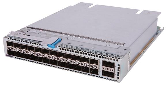
Technical specifications
Table2-84 Technical specifications
|
Item |
Specification |
|
Net weight |
2.00 kg (4.41 lb) |
|
Dimensions (H × W × D) |
40.1 × 214 × 274 mm (1.58 × 8.43 × 10.79 in) |
|
Power consumption |
· Minimum: 19 W · Typical: 48 W · Maximum: 78 W |
|
Port quantity |
26 |
|
Port type |
· 2 × 100G QSFP28 fiber ports · 24 × 25G SFP28 fiber ports |
|
Available transceiver modules and cables |
· QSFP28 transceiver modules · QSFP28 DAC cables · QSFP28 AOC cables · QSFP+ transceiver modules · QSFP+ DAC cables · QSFP+ AOC cables · SFP28 transceiver modules · SFP28 DAC cables · SFP28 AOC cables · 10GE SFP+ transceiver modules · 10GE SFP+ DAC cables · 10GE SFP+ AOC cables |
|
Services |
The module provides data access and switching with 26 Ethernet fiber ports |
|
Hot swapping |
Supported |
Ports and LEDs
Figure2-83 LSWM124TG2H front panel
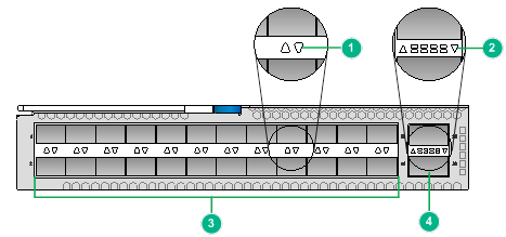
|
(1) 25GBASE-R-SFP28 fiber port LED |
(2) 100GBASE-R-QSFP28 fiber port LED |
|
(3) 25GBASE-R-SFP28 fiber ports |
(4) 100GBASE-R-QSFP28 fiber port |
Table2-85 LED description
|
LED |
Status |
Description |
|
SFP28 port LED |
Flashing |
The SFP28 port is sending or receiving data. |
|
On |
A link is present on the SFP28 port. |
|
|
Off |
No link is present on the SFP28 port. |
|
|
QSFP28 port LED |
Flashing |
The QSFP28 port is sending or receiving data. |
|
On |
A link is present on the QSFP28 port. |
|
|
Off |
No link is present on the QSFP28 port. |
LSWM124XGT2Q
View
Figure2-84 LSWM124XGT2Q interface card view
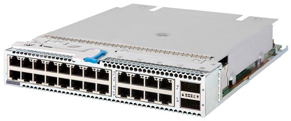
Technical specifications
Table2-86 Technical specifications
|
Item |
Specification |
|
Net weight |
3.00 kg (6.61 lb) |
|
Dimensions (H × W × D) |
40.1 × 214 × 274 mm (1.58 × 8.43 × 10.79 in) |
|
Power consumption |
· Minimum: 40 W · Typical: 81 W · Maximum: 123 W |
|
Port quantity |
26 |
|
Port type |
· 2 × 40GBASE-R-QSFP+ fiber ports · 24 × 10GBASE-T-RJ45 copper ports |
|
Available transceiver modules and cables |
· QSFP+ transceiver modules · QSFP+ DAC cables · QSFP+ AOC cables · Category 6A or 7 twisted pair cables |
|
Services |
The interface card with MACsec provides data access and switching with 24 Ethernet copper ports and 2 Ethernet fiber ports |
|
Hot swapping |
Supported |
Ports and LEDs
Figure2-85 LSWM124XGT2Q front panel
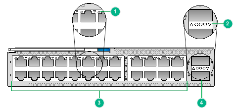
|
(1) 10GBASE-T-RJ45 copper port LED |
(2) 40GBASE-R-QSFP+ fiber port LED |
|
(3) 10GBASE-T-RJ45 copper ports |
(4) 40GBASE-R-QSFP+ fiber port |
Table2-87 LED description
|
LED |
Status |
Description |
|
RJ-45 port LED |
Flashing |
The RJ-45 port is receiving or sending data. |
|
On |
A link is present on the RJ-45 port. |
|
|
Off |
No link is present on the RJ-45 port. |
|
|
QSFP+ port LED |
Flashing |
The QSFP+ port is sending or receiving data. |
|
On |
A link is present on the QSFP+ port. |
|
|
Off |
No link is present on the QSFP+ port. |
LSWM1FWD0
View
Figure2-86 LSWM1FWD0 interface card view
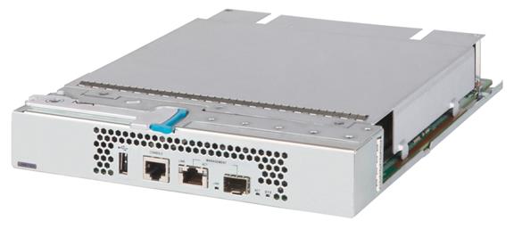
Technical specifications
Table2-88 Technical specifications
|
Item |
Specification |
|
Net weight |
2.1 kg (4.63 lb) |
|
Dimensions (H × W × D) |
40.1 × 214 × 274 mm (1.58 × 8.43 × 10.79 in) |
|
Power consumption |
Maximum: 150 W |
|
Flash |
8 MB |
|
Memory |
8 × memory slots Standard configuration: 32 GB (four 8 GB VLP RDIMMs) The module requires pairs of VLP RDIMMs that have the same specifications. |
|
SD card |
1 × built-in SD card slot Standard configuration: 8 GB |
|
Ports |
· 1 × console port · 1 × USB port (only for power output) · 2 × network management ports (one RJ-45 port and one SFP port) |
|
Services |
The module is a fourth-generation high performance firewall module. It provides features including firewall, VPN, content filtering, content identification, URL filtering, and NAT. By using this module on a switch, you can enhance the switch security capabilities without changing the network topology. |
|
Hot swapping |
Supported |
Ports and LEDs
Figure2-87 LSWM1FWD0 front panel
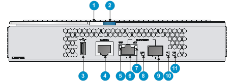
|
(1) Ejector lever |
(2) Latch |
|
(3) USB port (only for power output) |
(4) Console port (CONSOLE) |
|
(5) RJ-45 management Ethernet port LED (LINK) |
(6) RJ-45 management Ethernet port |
|
(7) RJ-45 management Ethernet port LED (ACT) |
(8) SFP fiber management Ethernet port LED (LINK) |
|
(9) SFP fiber management Ethernet port |
(10) SFP fiber management Ethernet port LED (ACT) |
|
(11) System status LED (SYS) |
|
Table2-89 LED description
|
LED |
Mark |
Status |
Description |
|
Management Ethernet port LED |
LINK |
Off |
No link is present on the port. |
|
Steady green |
A link is present on the port. |
||
|
ACT |
Off |
The port is not receiving or sending data. |
|
|
Flashing yellow |
The port is receiving or sending data. |
||
|
System status LED |
SYS |
Off |
No power is input or the module has failed. |
|
Slow flashing green (1 Hz) |
The system has started up and is operating correctly. |
||
|
Fast flashing green (8 Hz) |
The system is loading software. |
Fabric modules
LSXM1SFT16E1
View
Figure2-88 LSXM1SFT16E1 fabric module view
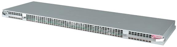
Technical specifications
Table2-90 Technical specifications
|
Item |
Specification |
|
Net weight |
9.80 kg (21.60 lb) |
|
Dimensions (H × W × D) |
40 × 853 × 279 mm (1.57 × 33.58 × 10.98 in) |
|
Power consumption |
· Minimum: 302 W · Typical: 332 W · Maximum: 452 W |
|
SDRAM |
4 GB |
|
Hot swapping |
Supported |
|
Applicable switch models |
S12516G-AF |
Buttons and LEDs
Figure2-89 LSXM1SFT16E1 front panel
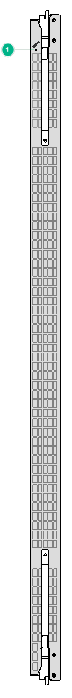
|
(1) RUN/ALM LED |
Table2-91 LED description
|
LED |
Status |
Description |
|
RUN/ALM LED |
Green |
The fabric module is operating correctly. |
|
Red |
The fabric module has failed or is loading software. |
|
|
Off |
The fabric module is not powered on or has not started loading software. |
LSXM1SFT16F2
View
Figure2-90 LSXM1SFT16F2 fabric module view
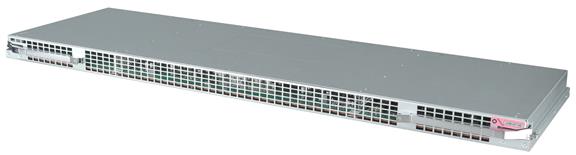
Technical specifications
Table2-92 Technical specifications
|
Item |
Specification |
|
Net weight |
9.70 kg (21.38 lb) |
|
Dimensions (H × W × D) |
40 × 853 × 279 mm (1.57 × 33.58 × 10.98 in) |
|
Power consumption |
· Minimum: 419 W · Typical: 545 W · Maximum: 691 W |
|
SDRAM |
8 GB |
|
Hot swapping |
Supported |
|
Applicable switch models |
S12516G-AF |
Buttons and LEDs
Figure2-91 LSXM1SFT16F2 front panel
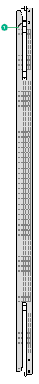
|
(1) RUN/ALM LED |
Table2-93 LED description
|
LED |
Status |
Description |
|
RUN/ALM LED |
Green |
The fabric module is operating correctly. |
|
Red |
The fabric module has failed or is loading software. |
|
|
Off |
The fabric module is not powered on or has not started loading software. |
LSXM3SFS16H2
View
Figure2-92 LSXM3SFS16H2 fabric module view
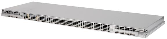
Technical specifications
Table2-94 Technical specifications
|
Item |
Specification |
|
Net weight |
9.95 kg (21.94 lb) |
|
Dimensions (H × W × D) |
40 × 853 × 279 mm (1.57 × 33.58 × 10.98 in) |
|
Power consumption |
· Minimum: 360 W · Typical: 547 W · Maximum: 729 W |
|
SDRAM |
4 GB |
|
Hot swapping |
Supported |
|
Applicable switch models |
S12516G-AF |
Buttons and LEDs
Figure2-93 LSXM3SFS16H2 front panel
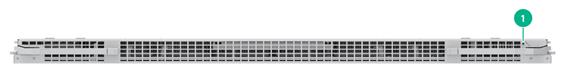
|
(1) RUN/ALM LED |
Table2-95 LED description
|
LED |
Status |
Description |
|
RUN/ALM LED |
Green |
The fabric module is operating correctly. |
|
Red |
The fabric module has failed or is loading software. |
|
|
Off |
The fabric module is not powered on or has not started loading software. |
LSXM3SFS16F2
View
Figure2-94 LSXM3SFS16F2 fabric module view
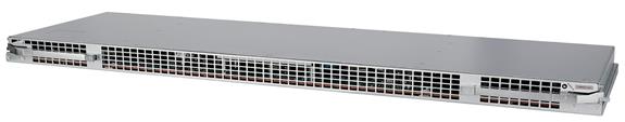
Technical specifications
Table2-96 Technical specifications
|
Item |
Specification |
|
Net weight |
9.40 kg (20.72 lb) |
|
Dimensions (H × W × D) |
40 × 853 × 279 mm (1.57 × 33.58 × 10.98 in) |
|
Power consumption |
· Minimum: 123 W · Typical: 172 W · Maximum: 257 W |
|
SDRAM |
4 GB |
|
Hot swapping |
Supported |
|
Applicable switch models |
S12516G-AF |
Buttons and LEDs
Figure2-95 LSXM3SFS16F2 front panel
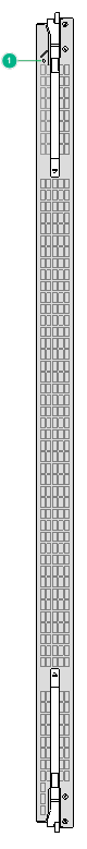
|
(1) RUN/ALM LED |
Table2-97 LED description
|
LED |
Status |
Description |
|
RUN/ALM LED |
Green |
The fabric module is operating correctly. |
|
Red |
The fabric module has failed or is loading software. |
|
|
Off |
The fabric module is not powered on or has not started loading software. |
LSXM3SFS16G2
View
Figure2-96 LSXM3SFS16G2 fabric module view
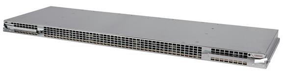
Technical specifications
Table2-98 Technical specifications
|
Item |
Specification |
|
Net weight |
10.20 kg (22.49 lb) |
|
Dimensions (H × W × D) |
40 × 853 × 279 mm (1.57 × 33.58 × 10.98 in) |
|
Power consumption |
· Minimum: 241 W · Typical: 317 W · Maximum: 500 W |
|
SDRAM |
4 GB |
|
Hot swapping |
Supported |
|
Applicable switch models |
S12516G-AF |
Buttons and LEDs
Figure2-97 LSXM3SFS16G2 front panel
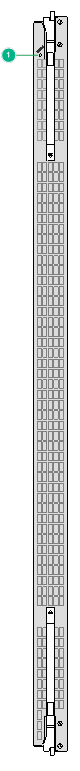
|
(1) RUN/ALM LED |
Table2-99 LED description
|
LED |
Status |
Description |
|
RUN/ALM LED |
Green |
The fabric module is operating correctly. |
|
Red |
The fabric module has failed or is loading software. |
|
|
Off |
The fabric module is not powered on or has not started loading software. |
LSXM1SFS08D2
View
Figure2-98 LSXM1SFS08D2 fabric module view
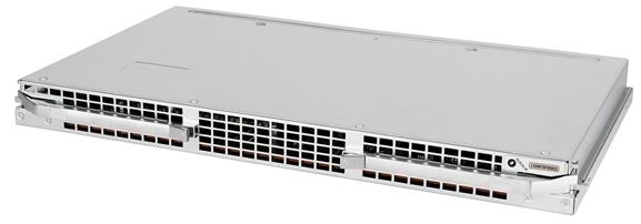
Technical specifications
Table2-100 Technical specifications
|
Item |
Specification |
|
Net weight |
5.10 kg (11.24 lb) |
|
Dimensions (H × W × D) |
40 × 453 × 279 mm (1.57 × 17.83 × 10.98 in) |
|
Power consumption |
· Minimum: 59 W · Typical: 116 W · Maximum: 145 W |
|
SDRAM |
2 GB |
|
Hot swapping |
Supported |
|
Applicable switch models |
S12508G-AF |
Buttons and LEDs
Figure2-99 LSXM1SFS08D2 front panel
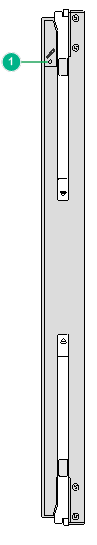
|
(1) RUN/ALM LED |
Table2-101 LED description
|
LED |
Status |
Description |
|
RUN/ALM LED |
Green |
The fabric module is operating correctly. |
|
Red |
The fabric module has failed or is loading software. |
|
|
Off |
The fabric module is not powered on or has not started loading software. |
LSXM3SFS08H2
View
Figure2-100 LSXM3SFS08H2 fabric module view
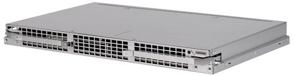
Technical specifications
Table2-102 Technical specifications
|
Item |
Specification |
|
Net weight |
5.15 kg (11.35 lb) |
|
Dimensions (H × W × D) |
40 × 453 × 279 mm (1.57 × 17.83 × 10.98 in) |
|
Power consumption |
· Minimum: 177 W · Typical: 245 W · Maximum: 363 W |
|
SDRAM |
4 GB |
|
Hot swapping |
Supported |
|
Applicable switch models |
S12508G-AF |
Buttons and LEDs
Figure2-101 LSXM3SFS08H2 front panel
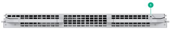
|
(1) RUN/ALM LED |
Table2-103 LED description
|
LED |
Status |
Description |
|
RUN/ALM LED |
Green |
The fabric module is operating correctly. |
|
Red |
The fabric module has failed or is loading software. |
|
|
Off |
The fabric module is not powered on or has not started loading software. |
LSXM2SFT08E1
View
Figure2-102 LSXM2SFT08E1 fabric module view
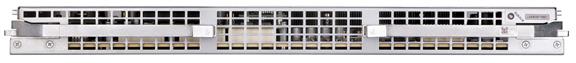
Technical specifications
Table2-104 Technical specifications
|
Item |
Specification |
|
Net weight |
5.20 kg (11.46 lb) |
|
Dimensions (H × W × D) |
40 × 453 × 279 mm (1.57 × 17.83 × 10.98 in) |
|
Power consumption |
· Minimum: 261 W · Typical: 340 W · Maximum: 446 W |
|
SDRAM |
8 GB |
|
Hot swapping |
Supported |
|
Applicable switch models |
S12508G-AF |
Buttons and LEDs
Figure2-103 LSXM2SFT08E1 front panel
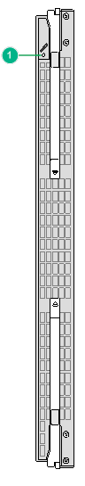
|
(1) RUN/ALM LED |
Table2-105 LED description
|
LED |
Status |
Description |
|
RUN/ALM LED |
Green |
The fabric module is operating correctly. |
|
Red |
The fabric module has failed or is loading software. |
|
|
Off |
The fabric module is not powered on or has not started loading software. |
LSXM2SFT08E2
View
Figure2-104 LSXM2SFT08E2 fabric module view
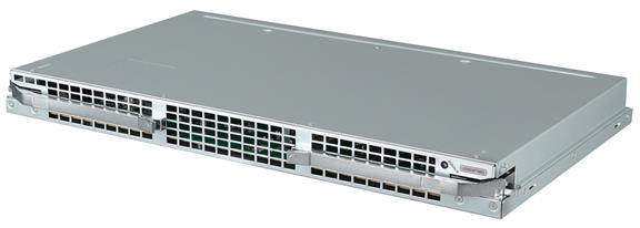
Technical specifications
Table2-106 Technical specifications
|
Item |
Specification |
|
Net weight |
4.90 kg (10.80 lb) |
|
Dimensions (H × W × D) |
40 × 453 × 279 mm (1.57 × 17.83 × 10.98 in) |
|
Power consumption |
· Minimum: 153 W · Typical: 176 W · Maximum: 223 W |
|
SDRAM |
4 GB |
|
Hot swapping |
Supported |
|
Applicable switch models |
S12508G-AF |
Buttons and LEDs
Figure2-105 LSXM2SFT08E2 front panel
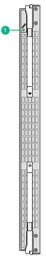
|
(1) RUN/ALM LED |
Table2-107 LED description
|
LED |
Status |
Description |
|
RUN/ALM LED |
Green |
The fabric module is operating correctly. |
|
Red |
The fabric module has failed or is loading software. |
|
|
Off |
The fabric module is not powered on or has not started loading software. |
LSXM1SFT08F2
View
Figure2-106 LSXM1SFT08F2 fabric module view
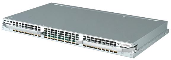
Technical specifications
Table2-108 Technical specifications
|
Item |
Specification |
|
Net weight |
5.20 kg (11.46 lb) |
|
Dimensions (H × W × D) |
40 × 453 × 279 mm (1.57 × 17.83 × 10.98 in) |
|
Power consumption |
· Minimum: 165 W · Typical: 397 W · Maximum: 444 W |
|
SDRAM |
4 GB |
|
Hot swapping |
Supported |
|
Applicable switch models |
S12508G-AF |
Buttons and LEDs
Figure2-107 LSXM1SFT08F2 front panel
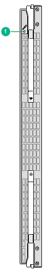
|
(1) RUN/ALM LED |
Table2-109 LED description
|
LED |
Status |
Description |
|
RUN/ALM LED |
Green |
The fabric module is operating correctly. |
|
Red |
The fabric module has failed or is loading software. |
|
|
Off |
The fabric module is not powered on or has not started loading software. |
LSXM3SFS08F2
View
Figure2-108 LSXM3SFS08F2 fabric module view
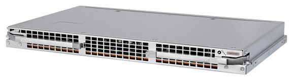
Technical specifications
Table2-110 Technical specifications
|
Item |
Specification |
|
Net weight |
4.50 kg (9.92 lb) |
|
Dimensions (H × W × D) |
40 × 453 × 279 mm (1.57 × 17.83 × 10.98 in) |
|
Power consumption |
· Minimum: 68 W · Typical: 86 W · Maximum: 124 W |
|
SDRAM |
4 GB |
|
Hot swapping |
Supported |
|
Applicable switch models |
S12508G-AF |
Buttons and LEDs
Figure2-109 LSXM3SFS08F2 front panel

|
(1) RUN/ALM LED |
Table2-111 LED description
|
LED |
Status |
Description |
|
RUN/ALM LED |
Green |
The fabric module is operating correctly. |
|
Red |
The fabric module has failed or is loading software. |
|
|
Off |
The fabric module is not powered on or has not started loading software. |
LSXM3SFS08G2
View
Figure2-110 LSXM3SFS08G2 fabric module view
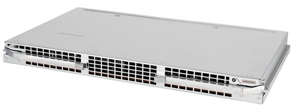
Technical specifications
Table2-112 Technical specifications
|
Item |
Specification |
|
Net weight |
5.10 kg (11.24 lb) |
|
Dimensions (H × W × D) |
40 × 453 × 279 mm (1.57 × 17.83 × 10.98 in) |
|
Power consumption |
· Minimum: 137 W · Typical: 176 W · Maximum: 259 W |
|
SDRAM |
4 GB |
|
Hot swapping |
Supported |
|
Applicable switch models |
S12508G-AF |
Buttons and LEDs
Figure2-111 LSXM3SFS08G2 front panel
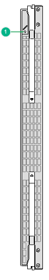
|
(1) RUN/ALM LED |
Table2-113 LED description
|
LED |
Status |
Description |
|
RUN/ALM LED |
Green |
The fabric module is operating correctly. |
|
Red |
The fabric module has failed or is loading software. |
|
|
Off |
The fabric module is not powered on or has not started loading software. |
LSXM1SFT04F2
View
Figure2-112 LSXM1SFT04F2 fabric module view
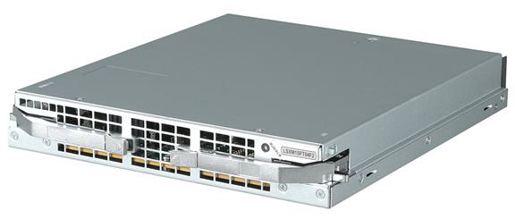
Technical specifications
Table2-114 Technical specifications
|
Item |
Specification |
|
Net weight |
2.90 kg (6.39 lb) |
|
Dimensions (H × W × D) |
40 × 243 × 279 mm (1.57 × 9.57 × 10.98 in) |
|
Power consumption |
· Minimum: 146 W · Typical: 172 W · Maximum: 206 W |
|
SDRAM |
4 GB |
|
Hot swapping |
Supported |
|
Applicable switch models |
S12504G-AF |
Buttons and LEDs
Figure2-113 LSXM1SFT04F2 front panel

|
(1) RUN/ALM LED |
Table2-115 LED description
|
LED |
Status |
Description |
|
RUN/ALM LED |
Green |
The fabric module is operating correctly. |
|
Red |
The fabric module has failed or is loading software. |
|
|
Off |
The fabric module is not powered on or has not started loading software. |
LSXM3SFS04G2
View
Figure2-114 LSXM3SFS04G2 fabric module view

Technical specifications
Table2-116 Technical specifications
|
Item |
Specification |
|
Net weight |
2.90 kg (6.39 lb) |
|
Dimensions (H × W × D) |
40 × 243 × 279 mm (1.57 × 9.57 × 10.98 in) |
|
Power consumption |
· Minimum: 68 W · Typical: 90 W · Maximum: 119 W |
|
SDRAM |
4 GB |
|
Hot swapping |
Supported |
|
Applicable switch models |
S12504G-AF |
Buttons and LEDs
Figure2-115 LSXM3SFS04G2 front panel
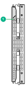
|
(1) RUN/ALM LED |
Table2-117 LED description
|
LED |
Status |
Description |
|
RUN/ALM LED |
Green |
The fabric module is operating correctly. |
|
Red |
The fabric module has failed or is loading software. |
|
|
Off |
The fabric module is not powered on or has not started loading software. |
Fabric module filler panels
Table2-118 Weights and dimensions of the fabric module filler panels
|
Model |
Net weight |
Height |
Width |
Depth |
|
Fabric module filler panel for the S12516G-AF switch |
2.8 kg (6.17 lb) |
40 mm (1.57 in) |
853 mm (33.58 in) |
136 mm (5.35 in) |
|
Fabric module filler panel for the S12508G-AF switch |
1.6 kg (3.53 lb) |
40 mm (1.57 in) |
453 mm (17.83 in) |
133 mm (5.24 in) |
|
Fabric module filler panel for the S12504G-AF switch |
0.9 kg (1.98 lb) |
40 mm (1.57 in) |
243 mm (9.57 in) |
136 mm (5.35 in) |
3 Power modules
|
|
CAUTION: You must install power modules of the same model for the switch. |
The switch supports N+N (dual power input sources) or N+1 (single power input source) power module redundancy. Determine the number of power modules based on the power supply mode and system power consumption. Make sure the maximum total output power of the installed power modules is greater than the system power consumption. Reserve a 20% power surplus as a best practice.
The power module shuts down automatically when its temperature exceeds the acceptable range. When the temperature returns to the acceptable range, the power module automatically restarts.
PSR2400-54A
View
Figure3-1 PSR2400-54A power module view

Technical specifications
Table3-1 Technical specifications
|
Item |
Specification |
|
Net weight |
1.90 kg (4.19 lb) |
|
Dimensions (H × W × D) |
41 × 100 × 332 mm (1.61 × 3.94 × 13.07 in) |
|
Rated input voltage range |
100 to 240 VAC @ 50 or 60 Hz |
|
Rated output voltage |
54 VDC |
|
Maximum input current |
16 A |
|
Maximum output current |
44.5 A |
|
Maximum output power |
· 1200 W @ 110 VAC · 2400 W @ 220 VAC |
|
Heat dissipation |
Equipped with fans, rear-to-front airflow (from the golden plating to the front panel) |
|
Hot swapping |
Supported |
|
Operating temperature |
–10°C to +55°C (14°F to 131°F) |
|
Storage temperature |
–40°C to +70°C (–40°F to +158°F) |
|
Applicable switch models |
All S12500G-AF switch models |
LEDs
Figure3-2 PSR2400-54A front panel
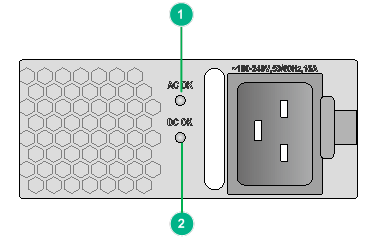
|
(1) Input status LED (AC OK) |
(2) Output status LED (DC OK) |
Table3-2 LED description
|
LED |
Status |
Description |
|
Input status LED (AC OK) |
Off |
· No power input. · The power module is in self-protection state because of low input voltage. |
|
Green |
Normal power input. |
|
|
Output status LED (DC OK) |
Green |
Normal power output. |
|
Red |
Power output of the power module is abnormal. The power module has an output shortcircuit, output overcurrent, output overvoltage, input undervoltage, or remote shutdown alarm and has entered self-protection state. |
|
|
Amber |
An overtemperature alarm was triggered. |
PSR3000-54A
View
Figure3-3 PSR3000-54A power module view
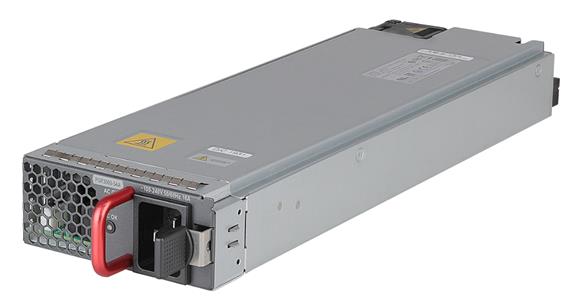
Technical specifications
Table3-3 Technical specifications
|
Item |
Specification |
|
Net weight |
2.1 kg (4.63 lb) |
|
Dimensions (H × W × D) |
41 × 100 × 332 mm (1.61 × 3.94 × 13.07 in) |
|
Rated input voltage range |
· AC input: 100 to 240 VAC @ 50 or 60 Hz · HVDC input: 240 VDC |
|
Rated output voltage |
54 VDC |
|
Maximum input current |
16 A |
|
Maximum output current |
55.6 A |
|
Maximum output power |
· 1200 W @ 110 VAC · 2400 W @ 175 to 200 VAC · 3000 W @ 220 VAC · 3000 W @ 240 VDC |
|
Heat dissipation |
Equipped with fans, rear-to-front airflow (from the golden plating to the front panel) |
|
Hot swapping |
Supported |
|
Operating temperature |
–10°C to +55°C (14°F to 131°F) |
|
Storage temperature |
–40°C to +70°C (–40°F to +158°F) |
|
Applicable switch models |
All S12500G-AF switch models |
LEDs
Figure3-4 PSR3000-54A front panel
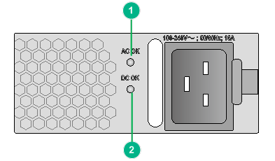
|
(1) Input status LED (AC OK) |
(2) Output status LED (DC OK) |
Table3-4 LED description
|
LED |
Status |
Description |
|
Input status LED (AC OK) |
Off |
· No power input. · The power module is in self-protection state because of low input voltage. |
|
Green |
Normal power input. |
|
|
Output status LED (DC OK) |
Green |
Normal power output. |
|
Red |
Power output of the power module is abnormal. The power module has an output shortcircuit, output overcurrent, output overvoltage, input undervoltage, or remote shutdown alarm and has entered self-protection state. |
|
|
Amber |
An overtemperature alarm was triggered. |
PSR2400-54AA-B
View
Figure3-5 PSR2400-54AA-B power module view
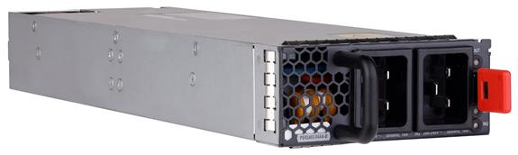
Technical specifications
Table3-5 Technical specifications
|
Item |
Specification |
|
Net weight |
1.95 kg (4.30 lb) |
|
Dimensions (H × W × D) |
41 × 100 × 332 mm (1.61 × 3.94 × 13.07 in) |
|
Rated input voltage range |
100 to 240 VAC @ 50 or 60 Hz |
|
Rated output voltage |
54 VDC |
|
Maximum input current |
16 A |
|
Maximum output current |
44.5 A |
|
Maximum output power |
· 1200 W @ 110 VAC · 2400 W @ 220 VAC |
|
Heat dissipation |
Equipped with fans, rear-to-front airflow (from the golden plating to the front panel) |
|
Hot swapping |
Supported |
|
Operating temperature |
–10°C to +55°C (14°F to 131°F) |
|
Storage temperature |
–40°C to +70°C (–40°F to +158°F) |
|
Applicable switch models |
All S12500G-AF switch models |
LEDs
Figure3-6 PSR2400-54AA-B front panel
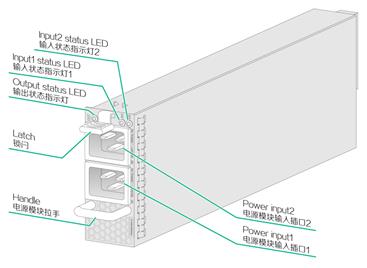
Table3-6 LED description
|
LED |
Status |
Description |
|
Input1 status LED (IN1) |
Off |
No power input. |
|
Green |
Normal power input. |
|
|
Red |
The input voltage is too low. |
|
|
Input2 status LED (IN2) |
Off |
No power input. |
|
Green |
Normal power input. |
|
|
Red |
The input voltage is too low. |
|
|
Output status LED (OUT) |
Off |
No power output. |
|
Green |
Normal power output. |
|
|
Red |
Power output of the power module is abnormal. The power module has an output shortcircuit, output overcurrent, output overvoltage, input undervoltage, or remote shutdown alarm and has entered self-protection state. |
|
|
Amber |
An overtemperature alarm was triggered. |
PSR2400-54D
View
Figure3-7 PSR2400-54D power module view
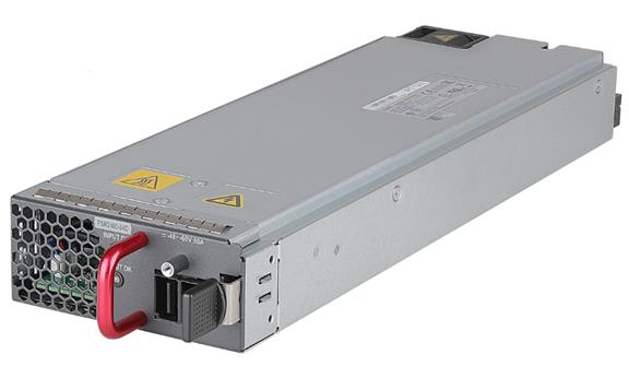
Technical specifications
Table3-7 Technical specifications
|
Item |
Specification |
|
Net weight |
1.9 kg (4.19 lb) |
|
Dimensions (H × W × D) |
41 × 100 × 332 mm (1.61 × 3.94 × 13.07 in) |
|
Rated input voltage range |
–48 to –60 VDC |
|
Rated output voltage |
54 VDC |
|
Maximum input current |
80 A |
|
Maximum output current |
44.5 A |
|
Maximum output power |
2400 W |
|
Heat dissipation |
Equipped with fans, rear-to-front airflow (from the golden plating to the front panel) |
|
Hot swapping |
Supported |
|
Operating temperature |
–10°C to +55°C (14°F to 131°F) |
|
Storage temperature |
–40°C to +70°C (–40°F to +158°F) |
|
Applicable switch models |
All S12500G-AF switch models |
LEDs
Figure3-8 PSR2400-54D front panel
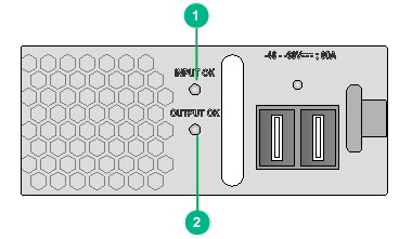
|
(1) Input status LED (INPUT OK) |
(2) Output status LED (OUTPUT OK) |
Table3-8 LED description
|
LED |
Status |
Description |
|
Input status LED (INPUT OK) |
Off |
· No power input. · The power module is in self-protection state because of low input voltage. |
|
Green |
Normal power input. |
|
|
Output status LED (OUTPUT OK) |
Green |
Normal power output. |
|
Red |
Power output of the power module is abnormal. The power module has an output shortcircuit, output overcurrent, output overvoltage, input undervoltage, or remote shutdown alarm and has entered self-protection state. |
|
|
Amber |
An overtemperature alarm was triggered. |
PSR3000-54AHD
View
Figure3-9 PSR3000-54AHD power module view
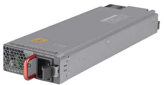
Technical specifications
Table3-9 Technical specifications
|
Item |
Specification |
|
Net weight |
2.1 kg (4.63 lb) |
|
Dimensions (H × W × D) |
41 × 100 × 332 mm (1.61 × 3.94 × 13.07 in) |
|
Rated input voltage range |
100 to 240 VAC @ 50 or 60 Hz |
|
Rated output voltage |
54 VDC |
|
Maximum input current |
16 A |
|
Maximum output current |
44.5 A |
|
Maximum output power |
· 1200 W @ 110 VAC · 2400 W @ 220 VAC |
|
Heat dissipation |
Equipped with fans, rear-to-front airflow (from the golden plating to the front panel) |
|
Hot swapping |
Supported |
|
Operating temperature |
–10°C to +55°C (14°F to 131°F) |
|
Storage temperature |
–40°C to +70°C (–40°F to +158°F) |
|
Applicable switch models |
All S12500G-AF switch models |
LEDs
Figure3-10 PSR3000-54AHD front panel
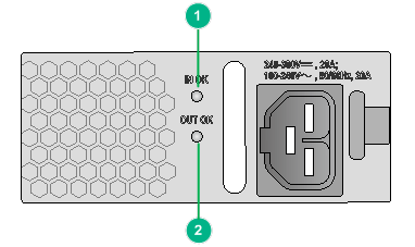
|
(1) Input status LED (IN OK) |
(2) Output status LED (OUT OK) |
Table3-10 LED description
|
LED |
Status |
Description |
|
Input status LED (IN OK) |
Off |
· No power input. · The power module is in self-protection state because of low input voltage. |
|
Green |
Normal power input. |
|
|
Output status LED (OUT OK) |
Green |
Normal power output. |
|
Amber |
An overtemperature alarm was triggered. |
|
|
Red |
Power output of the power module is abnormal. The power module has an output overcurrent, output overvoltage, input undervoltage, or remote shutdown alarm and has entered self-protection state. |
4 Fan trays
A fan tray provides a RUN and ALM LED pair for each fabric module it covers.
· On the S12516G-AF and S12508G-AF fan trays, the fabric module LED pairs correspond to the fabric modules the fan tray covers from left to right.
· On the S12504G-AF fan tray, the extend lines of the fabric module LED pairs correspond to the fabric module the fan tray covers from left to right.
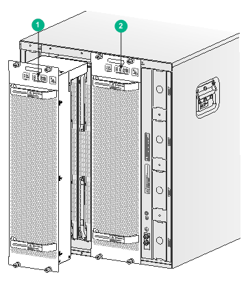
|
(1) LEDs for fabric module slots 10 to 12 |
|
(2) LEDs for fabric module slots 13 to 15 |
Figure4-2 Corresponding relations between the LEDs on the S12504G-AF fan trays and fabric module slots
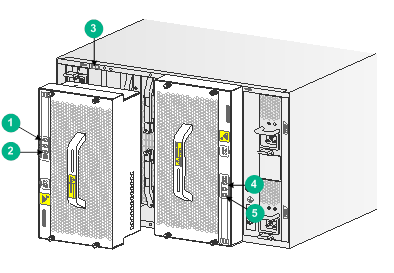
|
(1) LEDs for fabric module slot 6 |
(2) LEDs for fabric module slot 8 |
|
(3) Fabric module slot number |
(4) LEDs for fabric module slot 9 |
|
(5) LEDs for fabric module slot 11 |
|
LSXM116XFANH (high performance)
View
Figure4-3 LSXM116XFANH (high performance) fan tray view
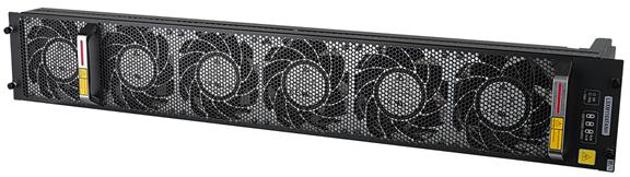
Technical specifications
Table4-2 Technical specifications
|
Item |
Specification |
|
Net weight |
8.4 kg (18.52 lb) |
|
Dimensions (H × W × D) |
144 × 927 × 154 mm (5.67 × 36.50 × 6.06 in) |
|
Power consumption |
· Minimum: 59 W · Typical: 725 W · Maximum: 2030 W |
|
Number of fans |
6 |
|
Fan diameter |
134 mm (5.28 in) |
|
Maximum air flow rate |
1860 CFM (52.67 m3/min) |
|
Airflow direction |
Air drawn in from the faceplate |
|
Noise reduction after poweron |
Supported |
|
Auto speed adjustment |
Supported |
|
Alarm detection |
Supported |
|
Supported |
|
|
Hot swapping |
Supported |
|
Applicable switch models |
S12516G-AF |
LEDs
Figure4-4 LSXM116XFANH (high performance) front panel
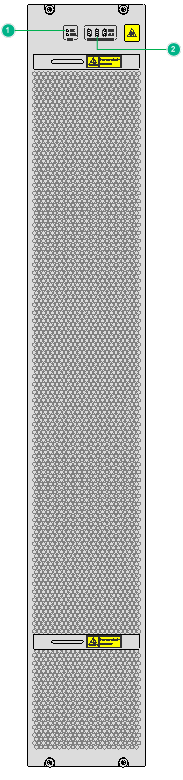
|
(1) Fan tray status LEDs (FAN) |
(2) Fabric module status LEDs (SWITCHING FABRIC) |
Table4-3 Fan tray status LED description
|
OK |
FAIL |
Description |
|
On |
Off |
The fan tray is operating correctly. |
|
Off |
On |
The fan tray is faulty. |
|
Off |
Off |
The fan tray is not powered on. |
Table4-4 Description for fabric module status LEDs on the fan tray
|
RUN |
ALM |
Description |
|
Flashing (once per second) |
Off |
The fabric module is operating correctly. |
|
Off |
On |
The fabric module has failed. |
|
Flashing (once per second) |
On |
· The fabric module is loading software. · The fabric module is operating incorrectly. For example, the operating temperature exceeds the acceptable range. |
|
Off |
Off |
The fabric module has not started or is not powered on. |
|
On |
On |
The fabric module is starting up. |
LSXM116XFAN
View
Figure4-5 LSXM116XFAN fan tray view
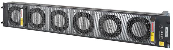
Technical specifications
Table4-5 Technical specifications
|
Item |
Specification |
|
Net weight |
6.7 kg (14.77 lb) |
|
Dimensions (H × W × D) |
144 × 927 × 154 mm (5.67 × 36.50 × 6.06 in) |
|
Power consumption |
· Minimum: 33 W · Typical: 206 W · Maximum: 793 W |
|
Number of fans |
6 |
|
Fan diameter |
120 mm (4.72 in) |
|
Maximum air flow rate |
1020 CFM (28.88 m3/min) |
|
Airflow direction |
Air drawn in from the faceplate |
|
Noise reduction after poweron |
Supported |
|
Auto speed adjustment |
Supported |
|
Alarm detection |
Supported |
|
Electrical label |
Supported |
|
Hot swapping |
Supported |
|
Applicable switch models |
S12516G-AF |
LEDs
Figure4-6 LSXM116XFAN front panel
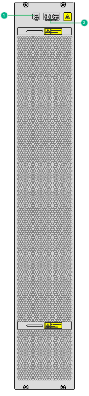
|
(1) Fan tray status LEDs (FAN) |
(2) Fabric module status LEDs (SWITCHING FABRIC) |
Table4-6 Fan tray status LED description
|
OK |
FAIL |
Description |
|
On |
Off |
The fan tray is operating correctly. |
|
Off |
On |
The fan tray is faulty. |
|
Off |
Off |
The fan tray is not powered on. |
Table4-7 Description for fabric module status LEDs on the fan tray
|
RUN |
ALM |
Description |
|
Flashing (once per second) |
Off |
The fabric module is operating correctly. |
|
Off |
On |
The fabric module has failed. |
|
Flashing (once per second) |
On |
· The fabric module is loading software. · The fabric module is operating incorrectly. For example, the operating temperature exceeds the acceptable range. |
|
Off |
Off |
The fabric module has not started or is not powered on. |
|
On |
On |
The fabric module is starting up. |
LSXM108XFANH (high performance)
View
Figure4-7 LSXM108XFANH (high performance) fan tray view
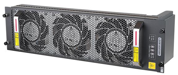
Technical specifications
Table4-8 Technical specifications
|
Item |
Specification |
|
Net weight |
4.4 kg (9.70 lb) |
|
Dimensions (H × W × D) |
144 × 527 × 154 mm (5.67 × 20.75 × 6.06 in) |
|
Power consumption |
· Minimum: 35 W · Typical: 410 W · Maximum: 1000 W |
|
Number of fans |
3 |
|
Fan diameter |
134 mm (5.28 in) |
|
Maximum air flow rate |
930 CFM (26.33 m3/min) |
|
Airflow direction |
Air drawn in from the faceplate |
|
Noise reduction after poweron |
Supported |
|
Auto speed adjustment |
Supported |
|
Alarm detection |
Supported |
|
Electrical label |
Supported |
|
Hot swapping |
Supported |
|
Applicable switch models |
S12508G-AF |
LEDs
Figure4-8 LSXM108XFANH (high performance) front panel

|
(1) Fan tray status LEDs (FAN) |
(2) Fabric module status LEDs (SWITCHING FABRIC) |
Table4-9 Fan tray status LED description
|
OK |
FAIL |
Description |
|
On |
Off |
The fan tray is operating correctly. |
|
Off |
On |
The fan tray is faulty. |
|
Off |
Off |
The fan tray is not powered on. |
Table4-10 Description for fabric module status LEDs on the fan tray
|
RUN |
ALM |
Description |
|
Flashing (once per second) |
Off |
The fabric module is operating correctly. |
|
Off |
On |
The fabric module has failed. |
|
Flashing (once per second) |
On |
· The fabric module is loading software. · The fabric module is operating incorrectly. For example, the operating temperature exceeds the acceptable range. |
|
Off |
Off |
The fabric module has not started or is not powered on. |
|
On |
On |
The fabric module is starting up. |
LSXM108XFAN
View
Figure4-9 LSXM108XFAN fan tray view
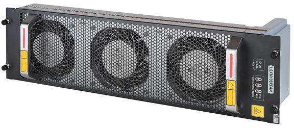
Technical specifications
Table4-11 Technical specifications
|
Item |
Specification |
|
Net weight |
3.8 kg (8.38 lb) |
|
Dimensions (H × W × D) |
144 × 527 × 154 mm (5.67 × 20.75 × 6.06 in) |
|
Power consumption |
· Minimum: 17 W · Typical: 103 W · Maximum: 395 W |
|
Number of fans |
3 |
|
Fan diameter |
120 mm (4.72 in) |
|
Maximum air flow rate |
510 CFM (14.44 m3/min) |
|
Airflow direction |
Air drawn in from the faceplate |
|
Noise reduction after poweron |
Supported |
|
Auto speed adjustment |
Supported |
|
Alarm detection |
Supported |
|
Electrical label |
Supported |
|
Hot swapping |
Supported |
|
Applicable switch models |
S12508G-AF |
LEDs
Figure4-10 LSXM108XFAN front panel
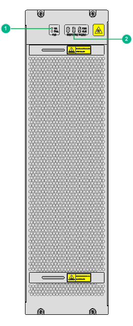
|
(1) Fan tray status LEDs (FAN) |
(2) Fabric module status LEDs (SWITCHING FABRIC) |
Table4-12 Fan tray status LED description
|
OK |
FAIL |
Description |
|
On |
Off |
The fan tray is operating correctly. |
|
Off |
On |
The fan tray is faulty. |
|
Off |
Off |
The fan tray is not powered on. |
Table4-13 Description for fabric module status LEDs on the fan tray
|
RUN |
ALM |
Description |
|
Flashing (once per second) |
Off |
The fabric module is operating correctly. |
|
Off |
On |
The fabric module has failed. |
|
Flashing (once per second) |
On |
· The fabric module is loading software. · The fabric module is operating incorrectly. For example, the operating temperature exceeds the acceptable range. |
|
Off |
Off |
The fabric module has not started or is not powered on. |
|
On |
On |
The fabric module is starting up. |
LSXM104XFANH (high performance)
View
Figure4-11 LSXM104XFANH (high performance) fan tray view
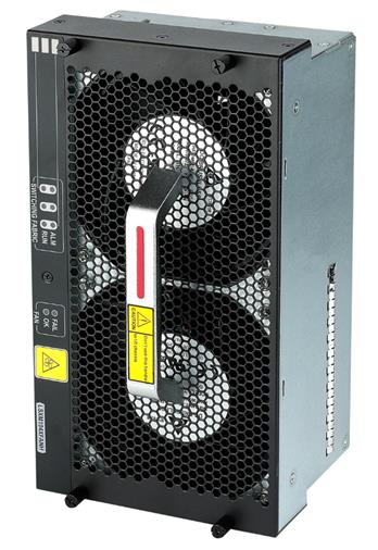
Technical specifications
Table4-14 Technical specifications
|
Item |
Specification |
|
Net weight |
3.0 kg (6.61 lb) |
|
Dimensions (H × W × D) |
144 × 263 × 102 mm (5.67 × 10.35 × 4.02 in) |
|
Power consumption |
· Minimum: 19.4 W · Typical: 86.4 W · Maximum: 590 W |
|
Number of fans |
2 |
|
Fan diameter |
120 mm (4.72 in) |
|
Maximum air flow rate |
560 CFM (15.86 m3/min) |
|
Airflow direction |
Air drawn in from the faceplate |
|
Noise reduction after power on |
Supported |
|
Auto speed adjustment |
Supported |
|
Alarm detection |
Supported |
|
Electrical label |
Supported |
|
Hot swapping |
Supported |
|
Applicable switch models |
S12504G-AF |
LEDs
Figure4-12 LSXM104XFANH (high performance) front panel
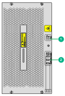
|
(1) Fan tray status LEDs (FAN) |
(2) Fabric module status LEDs (SWITCHING FABRIC) |
Table4-15 Fan tray status LED description
|
OK |
FAIL |
Description |
|
On |
Off |
The fan tray is operating correctly. |
|
Off |
On |
The fan tray is faulty. |
|
Off |
Off |
The fan tray is not powered on. |
Table4-16 Description for fabric module status LEDs on the fan tray
|
RUN |
ALM |
Description |
|
Flashing (once per second) |
Off |
The fabric module is operating correctly. |
|
Off |
On |
The fabric module has failed. |
|
Flashing (once per second) |
On |
· The fabric module is loading software. · The fabric module is operating incorrectly. For example, the operating temperature exceeds the acceptable range. |
|
Off |
Off |
The fabric module has not started or is not powered on. |
|
On |
On |
The fabric module is starting up. |
LSXM104XFAN
View
Figure4-13 LSXM104XFAN fan tray view
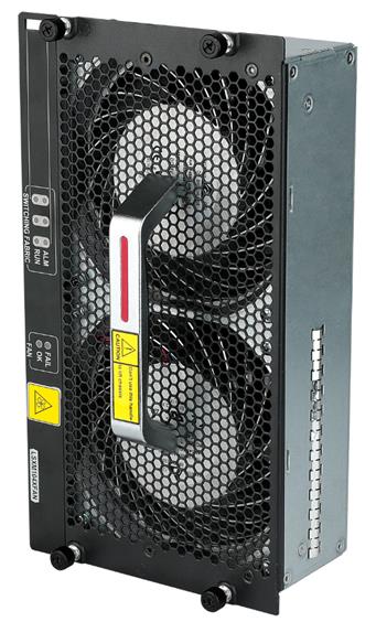
Technical specifications
Table4-17 Technical specifications
|
Item |
Specification |
|
Net weight |
1.8 kg (3.97 lb) |
|
Dimensions (H × W × D) |
144 × 263 × 67 mm (5.67 × 10.35 × 2.64 in) |
|
Power consumption |
· Minimum: 14 W · Typical: 66 W · Maximum: 255 W |
|
Number of fans |
2 |
|
Fan diameter |
120 mm (4.72 in) |
|
Maximum air flow rate |
340 CFM (9.63 m3/min) |
|
Airflow direction |
Air drawn in from the faceplate |
|
Noise reduction after poweron |
Supported |
|
Auto speed adjustment |
Supported |
|
Alarm detection |
Supported |
|
Electrical label |
Supported |
|
Hot swapping |
Supported |
|
Applicable switch models |
S12504G-AF |
LEDs
Figure4-14 LSXM104XFAN front panel
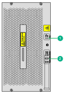
|
(1) Fan tray status LEDs (FAN) |
(2) Fabric module status LEDs (SWITCHING FABRIC) |
Table4-18 Fan tray LED description
|
OK |
FAIL |
Description |
|
On |
Off |
The fan tray is operating correctly. |
|
Off |
On |
The fan tray is faulty. |
|
Off |
Off |
The fan tray is not powered on. |
Table4-19 Description for fabric module status LEDs on the fan tray
|
RUN |
ALM |
Description |
|
Flashing (once per second) |
Off |
The fabric module is operating correctly. |
|
Off |
On |
The fabric module has failed. |
|
Flashing (once per second) |
On |
· The fabric module is loading software. · The fabric module is operating incorrectly. For example, the operating temperature exceeds the acceptable range. |
|
Off |
Off |
The fabric module has not started or is not powered on. |
|
On |
On |
The fabric module is starting up. |
5 Cables
Console cable
A console cable is an 8-core shielded cable, with a crimped RJ-45 connector at one end for connecting to the console port of the switch, and a DB-9 female connector at the other end for connecting to the serial port on the console terminal.
Figure5-1 Console cable

|
RJ-45 |
Signal |
DB-9 |
Signal |
|
1 |
RTS |
8 |
CTS |
|
2 |
DTR |
6 |
DSR |
|
3 |
TXD |
2 |
RXD |
|
4 |
SG |
5 |
SG |
|
5 |
SG |
5 |
SG |
|
6 |
RXD |
3 |
TXD |
|
7 |
DSR |
4 |
DTR |
|
8 |
CTS |
7 |
RTS |
Ethernet twisted pair cable
An Ethernet twisted pair cable consists of four pairs of insulated wires twisted together. It mainly transmits analog signals and is advantageous in transmitting data over shorter distances. The maximum transmission distance is 100 m (328.08 ft). To increase the transmission distance, you can install a maximum of four repeaters between two Ethernet twisted pair cables. With four repeaters installed, the maximum transmission distance can reach 500 m (1640.42 ft).
RJ-45 connector
An Ethernet twisted pair cable connects network devices through the RJ-45 connectors at the two ends. Figure5-2 shows the pinouts of an RJ-45 connector.
Figure5-2 RJ-45 connector pinout diagram
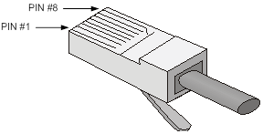
Cable pinouts
EIA/TIA cabling specifications define two standards: 568A and 568B for cable pinouts.
· Standard 568A—pin 1: white/green stripe, pin 2: green solid, pin 3: white/orange stripe, pin 4: blue solid, pin 5: white/blue stripe, pin 6: orange solid, pin 7: white/brown stripe, pin 8: brown solid.
· Standard 568B—pin 1: white/orange stripe, pin 2: orange solid, pin 3: white/green stripe, pin 4: blue solid, pin 5: white/blue stripe, pin 6: green solid, pin 7: white/brown stripe, pin 8: brown solid.
Cable type
Based on performance
Table5-1 Ethernet cable description
|
Type |
Description |
|
Category 5 |
Transmits data at a maximum speed of 100 Mbps, with a bandwidth of 100 MHz. |
|
Category 5e |
Transmits data at a maximum speed of 1000 Mbps, with a bandwidth of 100 MHz. |
|
Category 6 |
Transmits data at a speed higher than 1 Gbps, with a bandwidth of 250 MHz. |
|
Category 6A |
Transmits data at a speed higher than 10 Gbps, with a bandwidth of 500 MHz. |
|
Category 7 |
Transmits data at a speed higher than 10 Gbps, with a bandwidth of 600 MHz. |
Based on pinouts
Ethernet twisted pair cables can be classified into straight through and crossover cables based on their pinouts.
· Straight-through—The pinouts at both ends comply with standard 568B, as shown in Figure5-3.
· Crossover—The pinouts at one end comply with standard 568B, and those at the other end comply with standard 568A, as shown in Figure5-4.
Figure5-3 Straight-through cable
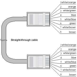
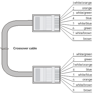
Pin assignments
Select an Ethernet twisted pair cable according to the RJ-45 Ethernet interface type on your device. An RJ-45 Ethernet interface can be MDI (for routers and PCs) or MDIX (for switches). For the pinouts of RJ-45 Ethernet interfaces, see Table5-2 and Table5-3.
Table5-2 RJ-45 MDI interface pinouts
|
10BASE-T/100BASE-TX |
1000BASE-T |
|||
|
Signal |
Function |
Signal |
Function |
|
|
1 |
Tx+ |
Send data |
BIDA+ |
Bi-directional data cable A+ |
|
2 |
Tx- |
Send data |
BIDA- |
Bi-directional data cable A- |
|
3 |
Rx+ |
Receive data |
BIDB+ |
Bi-directional data cable B+ |
|
4 |
Reserved |
N/A |
BIDC+ |
Bi-directional data cable C+ |
|
5 |
Reserved |
N/A |
BIDC- |
Bi-directional data cable C- |
|
6 |
Rx- |
Receive data |
BIDB- |
Bi-directional data cable B- |
|
7 |
Reserved |
N/A |
BIDD+ |
Bi-directional data cable D+ |
|
8 |
Reserved |
N/A |
BIDD- |
Bi-directional data cable D- |
Table5-3 RJ-45 MDI-X interface pinouts
|
Pin |
10BASE-T/100BASE-TX |
1000BASE-T |
||
|
Signal |
Function |
Signal |
Function |
|
|
1 |
Rx+ |
Receive data |
BIDB+ |
Bi-directional data cable B+ |
|
2 |
Rx- |
Receive data |
BIDB- |
Bi-directional data cable B- |
|
3 |
Tx+ |
Send data |
BIDA+ |
Bi-directional data cable A+ |
|
4 |
Reserved |
N/A |
BIDD+ |
Bi-directional data cable D+ |
|
5 |
Reserved |
N/A |
BIDD- |
Bi-directional data cable D- |
|
6 |
Tx- |
Send data |
BIDA- |
Bi-directional data cable A- |
|
7 |
Reserved |
N/A |
BIDC+ |
Bi-directional data cable C+ |
|
8 |
Reserved |
N/A |
BIDC- |
Bi-directional data cable C- |
To ensure normal communication, the pins for sending data on one port should correspond to the pins for receiving data on the peer port. When both of the ports on the two devices are MDI or MDIX, a crossover Ethernet cable is needed. A cross-over cable connects devices of the same type. When one port is MDI and the other is MDIX, a straight-through Ethernet cable is needed. A straight-through cable connects devices of different types.
An RJ-45 Ethernet interface with MDI/MDIX autosensing enabled can automatically negotiate pin roles. The S12500G-AF RJ-45 Ethernet interfaces support MDI/MDIX. By default, MDI/MDIX is enabled on a port.
Making an Ethernet twisted pair cable
1. Cut the cable to length with the crimping pliers.
2. Strip off an appropriate length of the cable sheath. The length is typically that of the RJ-45 connector.
3. Untwist the pairs so that they can lie flat, and arrange the colored wires based on the wiring specifications.
4. Cut the top of the wires even with one another. Insert the wires into the RJ-45 end and make sure the wires extend to the front of the RJ-45 end and make good contact with the metal contacts in the RJ-45 end and in the correct order.
5. Crimp the RJ-45 connector with the crimping pliers until you hear a click.
6. Repeat the above steps with the other end of the cable.
7. Use a cable tester to verify the connectivity of the cable.
Optical fiber
|
|
CAUTION: Use the same types of transceiver modules, pigtail cords, patch cords, and fiber cables. If you use single-mode optical fibers, the transceiver modules, pigtail cords, patch cords, and fiber cables must be single-mode. |
Optical fiber
Optical fibers are widely used in fiber-optic communications, which are advantageous for long-distance communications.
Optical fibers can be classified into the following types:
· Single mode fiber—It has a core size of 10 µm or smaller, and has a lower modal dispersion. It carries only a single ray of light. It is mostly used for communication over longer distances.
· Multi-mode fiber—It has a core size of 50 µm or 62.5 µm or higher, and has a higher modal dispersion than single-mode optical fiber. It is mostly used for communication over shorter distances.
Table5-4 Allowed maximum tensile force and crush load
|
Period of force |
Tensile load (N) |
Crush load (N/mm) |
|
Short period |
150 |
500 |
|
Long term |
80 |
100 |
Optical fiber cable
An optical fiber cable is a cable containing one or more optical fibers. The optical fiber elements are typically individually coated with plastic layers and contained in a protective tube. Optical fiber cables fall into single-mode and multi-mode.
Patch cord
A fiber that has connectors at both ends is called a patch cord. A patch cord connects one optical device to another for signal routing. Patch cords fall into single-mode and multi-mode patch cords.
· Single-mode patch cord—The jacket is yellow. It permits transmission over longer distances.
· Multi-mode patch cord—The jacket is orange. It permits transmission over shorter distances.
Patch cords are classified into SC, LC, FC, and so on based on interface type. The length of a patch cord can be 0.5 m (1.64 ft), 1 m (3.28 ft), 2 m (6.56 ft), 3 m (9.84 ft), 5 m (16.40 ft), 10 m (32.81 ft), and so on.
Pigtail cord
A pigtail cord is an optical fiber that has an optical connector on one end and a length of exposed fiber on the other. The end of the pigtail is fusion spliced to a fiber, connecting the fiber cable and transceiver.
Pigtail cords fall into single-mode (yellow) and multi-mode (orange), and can also be classified into SC, LC, FC, and so on based on interface type.
Fiber connector
Figure5-5 MPO connector

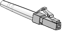
Precautions
· Make sure the fiber connector and fiber type match the transceiver module type.
· The fiber ports on the switch are provided with dust plugs. Insert the dust plugs into the fiber ports that you are not to use, to prevent particles from entering the ports.
· Fiber connectors must be protected under safe and reliable outer packing, and be fitted with dust caps. Fiber connectors must be installed with dust caps when they are not in use. Take care not to scratch their end face. Replace the dust cap if it is loose or polluted.
· Before connecting a fiber, use dust free paper and absolute alcohol to clean the end face of the fiber connector. You can brush the end face only in one direction. You also need to brush the end face of the fiber port.
· If the fiber has to pass through a metallic board hole, the hole must have a sleek and fully filleted surface (the filleting radius must be not less than 2 mm). When passing through a metallic board hole or bending along the acute side of mechanical parts, the fiber must wear jackets or cushions.
· Insert and remove a plug with care. Never exert a fierce force to the fiber or plug; otherwise the plug might be damaged or the fiber might be broken. Never pull, press or extrude the fiber fiercely. For the allowed maximum tensile load and crush load, see Table5-4.
SFP+/SFP28 DAC cable
You can use SFP+/SFP28 DAC cables to connect SFP+/SFP28 ports.
The SFP+ DAC cables available for the switch series are 10 G SFP+ Cu cables, as shown in Figure5-7.
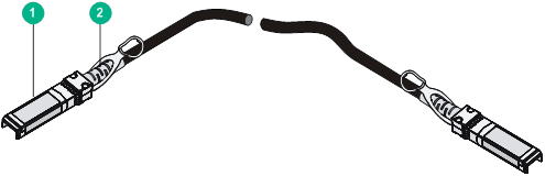
|
(1) Connector |
(2) Pull latch |
SFP28 AOC cable
You can use SFP28 AOC cables to connect SFP28 ports.
Figure5-8 SFP28 AOC cable
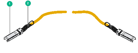
|
(1) Connector |
(2) Pull latch |
QSFP+ DAC/QSFP28 DAC cable
You can use QSFP+ DAC cables to connect QSFP+ ports.
You can use QSFP28 DAC cables to connect QSFP28 ports. The QSFP28 DAC cables are similar to QSFP+ DAC cables in appearance.
Figure5-9 QSFP+ DAC cable
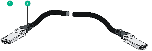
|
(1) Connector |
(2) Pull latch |
QSFP+ AOC/QSFP28 AOC cable
You can use QSFP+ AOC cables to connect QSFP+ ports.
You can use QSFP28 AOC cables to connect QSFP28 ports. The QSFP28 AOC cables are similar to QSFP+ AOC cables in appearance.
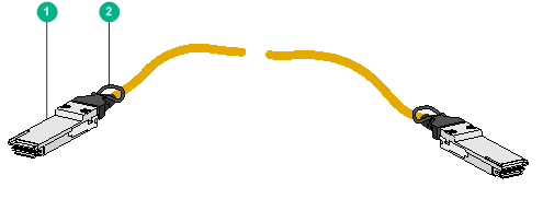
|
(1) Connector |
(2) Pull latch |
QSFP+ to SFP+/QSFP28 to SFP28 DAC cable
A QSFP+ to SFP+ DAC cable is a cable with one QSFP+ module at one end and four SFP+ modules at the other end.
A QSFP28 to SFP28 DAC cable is a cable with one QSFP28 module at one end and four SFP28 modules at the other end. The appearance of a QSFP28 to SFP28 DAC cable is similar to that of the QSFP+ to SFP+ DAC cable.
Figure5-11 QSFP+ to SFP+ DAC cable
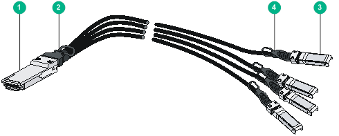
|
(1) QSFP+ connector |
(2) QSFP+ pull latch |
|
(3) SFP+ connector |
(4) SFP+ pull latch |
QSFP-DD cable
You can use QSFP-DD cables to connect QSFP-DD ports.
Figure5-12 QSFP-DD cable