- Table of Contents
- Related Documents
-
| Title | Size | Download |
|---|---|---|
| 01-Hardware Information and Specifications | 1.01 MB |
1 Product models and technical specifications
2000W AC power module (PSR2000-12A-C-A/PSR2000-12A-C-B)
1 Product models and technical specifications
Product models
This document is applicable to the following switch models:
|
Series |
Product model |
Product code |
|
H3C S9827 switch series |
S9827-128DH |
LS-9827-128DH |
|
|
NOTE: · To obtain the purchase information, see the product data sheet at https://www.h3c.com/en/Products_and_Solutions/InterConnect/Switches/ and pay attention to the switch product lifecycle management announcement at https://www.h3c.com/en/Support/Policy_Dynamics/Management_Strategy/Products_End_of_Life_Announcement/Switches/. · For information about product and software compatibility, see the release notes. |
Technical specifications
Table1-1 Technical specifications
|
Item |
LS-9827-128DH |
|
Physical specifications |
|
|
Dimensions (H × W × D, without package) |
175 × 442 × 760 mm (6.9 × 17.40 × 38.39 in) |
|
Dimensions (H × W × D, with package) |
391 × 655 × 1092 mm (15.40 × 25.79 × 42.99 in) |
|
Weight (fully configured with fan trays, power modules, and MPUs) |
≤ 40.2 kg (88.62 lb) |
|
Technical specifications |
|
|
Processor |
4 cores, 2.6 GHz |
|
DRAM memory |
16 GB |
|
NOR flash |
256 MB *2 (primary and backup) |
|
NAND flash |
64 GB eMMC flash |
|
Interface types and quantity |
|
|
Console port |
1 × serial console port |
|
Management Ethernet port |
1 × management Ethernet port |
|
USB port |
1 × USB2.0 port |
|
QSFP112 port |
128 × QSFP112 ports |
|
Fan trays, power modules, and interface modules |
|
|
Fan tray slot |
8 |
|
Power module slot |
4 |
|
MPU slot |
1 |
|
Power module specifications |
|
|
Power input |
AC input and DC input |
|
Power consumption |
|
|
Typical power consumption (Fully configured with copper cables, at 50% load) |
850 W |
|
Maximum power consumption (Fully configured with transceiver modules, at 100% load) |
3888 W |
|
Thermal consumption |
|
|
Typical thermal consumption |
Single-AC/dual-AC: 498 BTU/hr |
|
Maximum thermal consumption |
1464 BTU/hr |
|
Heat dissipation |
|
|
Heat dissipation method |
Air cooling |
|
Ventilation aisles |
Front-to-rear |
|
Reliability and availability |
|
|
Power module redundancy |
2+2 redundancy |
|
Fan redundancy |
7+1 redundancy |
|
Hot swapping |
Supported |
|
Mean time between failure (MTBF) (year) |
> 50 |
|
Mean time to repair (MTTR) (hour) |
< 1 |
|
Availability |
99.999927% |
|
Environment specifications |
|
|
Sound pressure level at 27°C (80.6°F) |
65.5 dB(A) |
|
Altitude |
0 m to +5000 m (0 ft to +16404.20 ft) |
|
Operating temperature |
0°C to 40°C (32°F to 104°F) Note: The allowed maximum temperature decreases by 0.33 °C (32.59°F) as the altitude increases by 100 m (328.08 ft) from 0 m (0 ft). |
|
Storage temperature |
–40°C to +70°C (–40°F to +158°F) |
|
Humidity |
5% RH to 95% RH, noncondensing |
|
Compliance |
|
|
Product compliance |
· Safety standards · EMC standards · Environmental and eco-friendly standards |
2 Chassis views
|
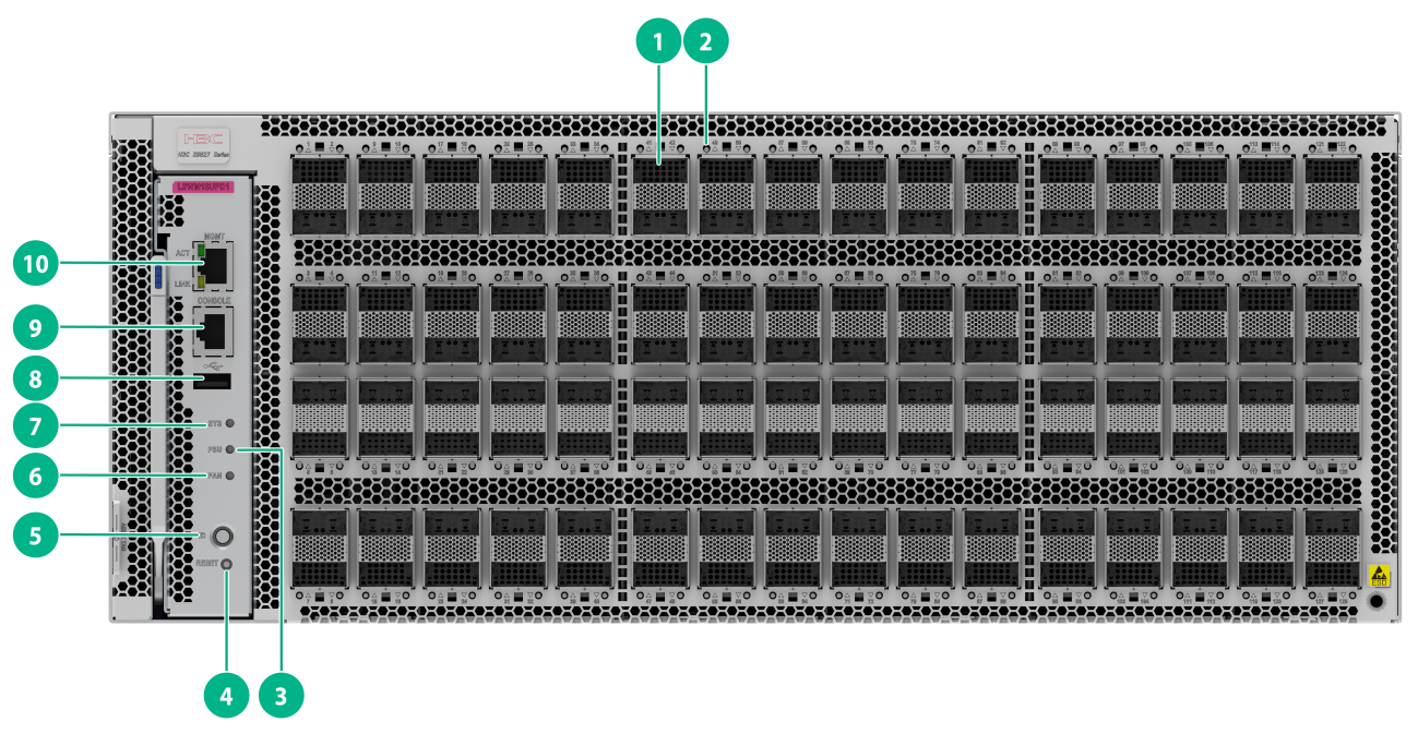
(1) QSFP112 Ethernet optical port |
(2) QSFP112 port LED |
|
(3) Power status LED (PSU) |
(4) RESET button |
|
(5) Location LED (ID) |
(6) Fan status LED (FAN) |
|
(7) System status LED (SYS) |
(8) USB port |
|
(9) Serial console port |
(10) Management Ethernet copper port (LINK/ACT) |
|
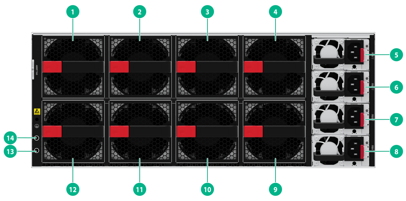
(1) Fan tray 1 |
(2) Fan tray 2 |
|
(3) Fan tray 3 |
(4) Fan tray 4 |
|
(5) Power module 1 |
(6) Power module 2 |
|
(7) Power module 3 |
(8) Power module 4 |
|
(9) Fan tray 5 |
(10) Fan tray 6 |
|
(11) Fan tray 7 |
(12) Power module 8 |
|
(13) Grounding screw 2 |
(14) Grounding screw 1 |
The switch came with fully-configured power modules in the four power modules slots. You can install two to four power modules for the switch as needed. In Figure2-2, PSR2000-12A-C-A AC power modules are installed in the four power module slots.
The switch came with eight fan tray slots empty. You must install eight fan trays of the same model for the switch. In Figure2-2, FAN-80B-1-C fan trays are installed in the eight fan tray slots.
The switch supports shipping with fan trays and power modules installed. To purchase a switch preinstalled with fans trays and power modules, contact marketing staff.
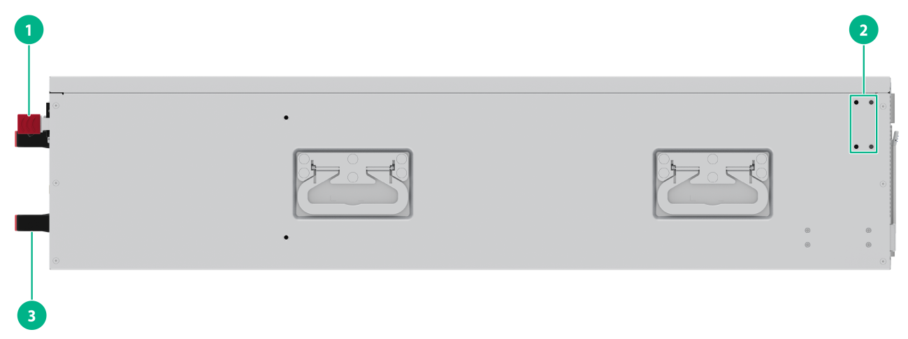
Figure2-3 Left view
|
(1) Handle |
(2) Installation position for the port-side chassis ear |
|
(3) Handle |
|
3 FRUs
The switch uses modular design. Table3-1 describes the FRUs available for the switch.
Table3-1 FRUs available for the switch
|
FRUs |
Product code |
LS-9827-128DH |
|
Power modules |
||
|
PSR2000-12A-C-A |
9803A0D9 |
Yes |
|
PSR2000-12A-C-B |
9803A1PG |
Yes |
|
Fan trays |
||
|
FAN-80B-1-C |
9803A0DC |
Yes |
|
MPUs |
||
|
LSWM1SUPD1 |
9803A1N9 |
Yes |
The switch can operate correctly with two power modules. You can install three power modules for 2+1 redundancy or four power modules for 2+2 redundancy.
To ensure heat dissipation, make sure all fan tray slots are installed with fan trays and install fan trays of the same model on the switch as a best practice.
Power modules
|
|
WARNING! When the switch has power modules in redundancy, you can replace a power module without powering off the switch. To avoid device damage and personal injury, make sure the power module is powered off before you replace it. |
You can select power modules as needed for the switch.
2000W AC power module (PSR2000-12A-C-A/PSR2000-12A-C-B)
Figure3-1 PSR2000-12A-C-A/PSR2000-12A-C-B power module
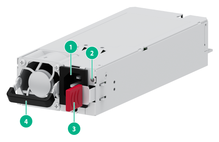
|
(1) AC power receptacle |
(2) Power module alarm LED |
|
(3) Latch |
(4) Handle |
For information about the power module LED, see "Power module LED."
Features
PSR2000-12A-C-A/PSR2000-12A-C-B is a power module with AC or HVDC input and DC output. It can provide up to 2000 W of output. Table3-2 describes the features provided by the PSR1600B-12A-B power module.
Table3-2 Features provided by the PSR2000-12A-C-A/PSR2000-12A-C-B power module
|
Feature |
Description |
|
Protection function |
Protection for input overcurrent, input undervoltage, output overvoltage, output shortcircuit, and overtemperature. |
|
Support for redundancy |
The power modules can work in N+1 or N+N redundant mode, and support load sharing. |
|
Support for hot swapping |
You can install or remove a power module when the switch is powered on. |
Technical specifications
Table3-3 Technical specifications
|
Item |
Specification |
|
Dimensions (H × W × D) (handle included) |
73.5 × 185 × 40 mm (2.89 × 7.28 × 1.57 in) |
|
Weight |
0.75 kg (1.65 lb) |
|
Rated AC input voltage range |
100 VAC to 240 VAC @ 50 or 60 Hz |
|
Max AC input voltage range |
90 VAC to 264 VAC |
|
Rated HVDC input voltage |
240 VDC |
|
Max HVDC input voltage range |
180 VDC to 320 VDC |
|
Rated input current |
12A Max @ 100 VAC to 240 VAC 10A Max @ 240 VDC |
|
Rated output current |
164 A |
|
Rated output voltage |
12.2 V |
|
Rated output power |
2000 W |
|
Melting current of power module fuse |
15 A |
|
Max. output current |
164 A |
|
Max. power |
2000 W |
Fan trays
|
|
CAUTION: The switch has eight fan tray slots. To ensure good ventilation of the switch, follow these guidelines to install and remove fan trays: · The switch comes with the fan tray slots empty. As a best practice to ensure adequate heat dissipation, install fan trays of the same model on the switch. Before powering on the switch, make sure the number of installed fan trays meets the minimum requirement. · Make sure all slots have a module or filler panel installed when the switch is operating. · If multiple fan trays fail on an operating switch, do not remove the fan trays at the same time. Replace the fan trays one after another and finish replacing each fan tray within 3 minutes. |
FAN-80B-1-C
Figure3-2 FAN-80B-1-C fan tray
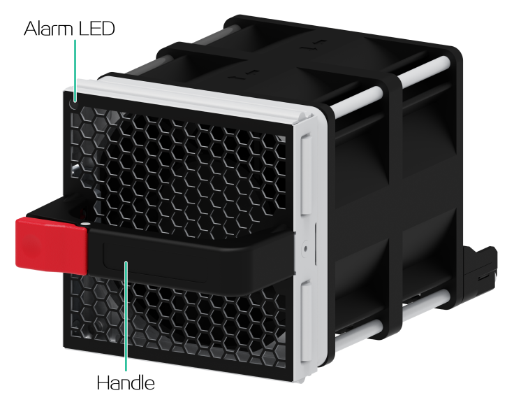
For information about the alarm LED, see "Fan tray alarm LED."
Features
The FAN-80B-1-C fan tray draws air from the port side to the fan tray faceplate side. The fan tray is small, hot swappable, and can automatically adjust the fan speed according to the device temperature.
Technical specifications
Table3-4 FAN-80B-1-C fan tray specifications
|
Item |
Specification |
|
Dimensions (H × W × D) (handle included) |
80 × 80 × 136 mm (3.15 × 3.15 × 5.35 in) |
|
Weight |
0.5 kg (1.10 lb) |
|
Airflow direction |
Air exhausted from the fan tray faceplate |
|
Max fan speed |
INLET: 16000 R.P.M OUTLET: 14000 R.P.M |
|
Max airflow |
163.92 CFM (3.68 m3/min) |
|
Operating voltage |
12 V |
|
Max power consumption |
105.6 W |
MPUs
LSWM1SUPD1
Figure3-3 LSWM1SUPD1 MPU

Technical specifications
Table3-5 LSWM1SUPD1 MPU specifications
|
Item |
Specification |
||
|
Weight |
1.90 kg (4.19 lb) |
||
|
Dimensions (H × W × D) |
151 × 33.5 × 309 mm (5.95 × 1.32 × 12.17 in) |
||
|
Power consumption |
45 W |
||
|
Processor |
4 cores, 2.6 GHz |
||
|
SDRAM |
16 GB |
||
|
Flash |
64 GB |
||
|
NVRAM |
N/A |
||
|
Connector type |
· RJ-45 · USB (Type A) |
||
|
Interface |
· 1 × console port · 1 × USB port · 1 × network management port (1 × RJ-45 port) |
||
|
Interface transmission speed |
· Console port: 9600 to 115200 bps (Default: 9600 bps) · Network management port (1 × RJ-45 port): 10/100/1000 Mbps, half/full duplex |
||
|
Hot swapping |
Supported |
||
|
Compatible switch model |
S9827-128DH |
Figure3-4 LSWM1SUPD1 MPU front view
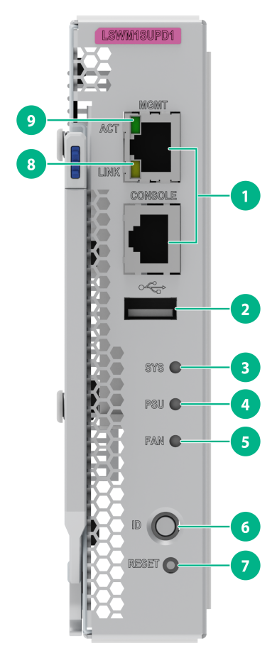
|
(1) Network management port |
(2) USB port |
|
(3) System status LED (SYS) |
(4) Power status LED (PSU) |
|
(5) Fan status LED (FAN) |
(6) Location LED (ID) |
|
(7) RESET button |
(8) Management Ethernet copper port LED (LINK) |
|
(9) Management Ethernet copper port LED (ACT) |
|
4 Ports
As a best practice, use H3C transceiver modules and cables for the switch. H3C transceiver modules and cables are subject to change over time. For the most up-to-date list of H3C transceiver modules and cables, contact H3C Support or marketing staff.
For information about the specifications of H3C transceiver modules and cables, see H3C Transceiver Modules User Guide.
Console port
The switch has a serial console port.
Table4-1 Console port specifications
|
Item |
Serial console port |
|
Connector type |
RJ-45 |
|
Compliant standard |
EIA/TIA-232 |
|
Operating mode |
Duplex Universal Asynchronous Receiver/Transmitter (duplex UART) |
|
Transmission baud rate |
9600 bps (default) to 115200 bps |
|
Services |
· Provides connection to an ASCII terminal. · Provides connection to the serial port of a local terminal (a PC for example) running a terminal emulation program. |
Management Ethernet port
The switch has one management Ethernet copper port. You can connect the port to a local PC for software loading and debugging or to a remote management station for remote management.
Table4-2 Management Ethernet port specifications
|
Item |
Specification |
|
Connector type |
RJ-45 |
|
Connector count |
1 × 10/100/1000BASE-T management port |
|
Compliant standard |
10/100/1000BASE-T management port: IEEE802.3ab |
|
Port transmission rate, duplex mode, and auto MDI/MDI-X |
· 10/100 Mbps, half/full duplex, auto MDI/MDI-X. · 1000 Mbps, full duplex, auto MDI/MDI-X. |
|
Transmission medium and max transmission distance |
10/100/1000BASE-T management port: 100 m (328.08 ft) over category-5 UTP cable. |
|
Functions and services |
Software upgrade and network management. |
USB port
The switch has one OHCI-compliant USB 3.0 port that can upload and download data at a rate up to 5 Gbps. You can use this USB port to access the file system on the flash of the switch, for example, to upload or download application and configuration files.
The USB port supplies power as per USB 3.0 specifications. Use only USB 3.0-compliant USB devices for the USB port. The port might not identify USB devices that are not compliant with USB 3.0.
|
|
NOTE: USB devices from different vendors vary in compatibilities and drivers. H3C does not guarantee correct operation of USB devices of all vendors on the switch. If a USB device fails to operate on the switch, replace it with one from another vendor. |
QSFP112 port
Table4-3 QSFP112 port specifications
|
Item |
Specification |
|
Interface name |
400 GE QSFP112 Ethernet optical interface |
|
Product compatibility |
128 × QSFP112 ports on the front panel |
|
Connector |
LC/MPO |
|
Description |
The 400 GE QSFP112 Ethernet optical interfaces are mainly used for transmitting and receiving 400 GE Ethernet optical interface services and being compatible with 200 GE and 100 GE Ethernet rates |
|
Compliant standard |
· IEEE802.3ba · IEEE802.3ck · IEEE802.3bm |
|
Optical interface attribute |
Depends on transceiver modules and cables |
|
Operating mode |
Full duplex |
|
Transceiver modules and cables |
· 100G QSFP28 modules · 100G QSFP28 copper cables · QSFP56-200G-SR4-MM850 · QSFP56-200G-FR4-WDM1300 · QSFP112-400G-VR4-MM850 · QSFP112-400G-DR4-SM1310 · QSFP112-400G-FR4-WDM1300 |
|
Support for interface splitting |
· Split into two 200 GE interfaces · Split into four 100 GE interfaces |
|
Other restrictions |
N/A |
5 LEDs
System status LED
The system status LED shows the operating status of the switch.
Table5-1 System status LED description
|
LED mark |
Status |
Description |
|
SYS |
Steady green |
The switch is operating correctly. |
|
Flashing green |
The switch is performing power-on self-test (POST). |
|
|
Steady red |
The system has failed to pass POST or a fault has occurred. |
|
|
Steady yellow |
Some ports have failed to pass POST and cannot operate correctly. |
|
|
Flashing blue (3 Hz) |
Helps identifying the switch. The S9827-128DH switch uses the ID LED to locate the device with the LED in flashing blue at 2 Hz. To identify the switch location, execute the locator blink blink-time command. This LED will flash blue at 3 Hz. |
|
|
Off |
The switch is powered off or has failed to start up. |
QSFP112 port LED
Table5-2 QSFP112 port LED description
|
LED status |
Description |
|
Steady green |
A transceiver module or cable has been correctly installed in the port. The port has a link and is operating at 400 Gbps. |
|
Flashing green |
The port is sending or receiving data at 400 Gbps. |
|
Steady yellow |
A transceiver module or cable has been correctly installed in the port. The port has a link and is operating at non-400 Gbps. |
|
Flashing yellow (3 Hz) |
The port is sending or receiving data at non-400 Gbps. |
|
Off |
No transceiver module or cable has been installed in the port, or no link is present on the port. |
Management Ethernet port LEDs
The switch provides a LINK/ACT LED for the management Ethernet copper port to indicate its operating status.
Table5-3 Management Ethernet copper port LED description
|
LED mark |
Status |
Description |
|
LINK |
Off |
No link is present on the port. |
|
Steady green |
The port is operating at 10/100/1000 Mbps. |
|
|
ACT |
Off |
The port is not receiving or sending data. |
|
Flashing yellow |
The port is receiving or sending data. |
Power module LED
A PSR2000-12A-C-A power module provides a LED to indicate the status of power input and power output.
Table5-4 Description for the LED on a PSR2000-12A-C-A power module
|
Status |
Description |
|
Steady green |
The power module is operating correctly. |
|
Flashing green at 1 Hz |
The power module has power input, and the system is in standby state and has not been powered on. |
|
Flashing green at 0.33 Hz |
The power module is in cold standby state with no power output. |
|
Flashing green at 2 Hz |
The power module firmware is being upgraded. |
|
Steady amber |
· A severe fault occurs on the power module · The power module has no power input but the other power module has power input. |
|
Steady amber at 1 Hz |
An alarm occurs on the power module. |
|
Off |
The power module does not have power input due to one of the following conditions: · The power cable is connected incorrectly. · The external power system is powered off. |
Fan tray alarm LED
Each fan tray panel has an alarm LED. For information about the alarm LED on a FAN-80B-1-C fan tray, see Table5-5
Table5-5 Description for the alarm LED on a FAN-80B-1-C fan tray
|
Status |
Description |
|
Steady green |
The fan tray is operating correctly. |
|
Steady red |
The fan tray is faulty. |
|
Off |
The fan tray is operating correctly or no power is present. |
Power status LED
The switch provides a power status LED on the panel to indicate the operating status of the power modules in the chassis.
Table5-6 Description for the power status LED
|
Mark |
Status |
Description |
|
PSU |
Steady green |
The power modules are operating correctly. |
|
Steady yellow |
The number of the faulty or absent power modules is 1 |
|
|
Steady red |
The number of the faulty or absent power modules is equal to or greater than 2. |
|
|
Off |
The device is powered off. |
Fan status LED
The switch provides a fan status LED on the panel to indicate the operating status of the fan trays in the chassis.
Table5-7 Fan status LED
|
Mark |
Status |
Description |
|
FAN |
Steady green |
The fan trays are operating correctly. |
|
Steady yellow |
The number of the faulty or absent fan trays is 1 |
|
|
Steady red |
The number of the faulty or absent fan trays is equal to or greater than 2. |
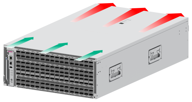
6 Cooling system
|
|
CAUTION: The chassis and power modules use separate air aisles. Make sure the two aisles are not blocked when the switch is operating. |
The switch uses a highly efficient front-rear air aisle cooling system to ensure adequate heat dissipation and improve system reliability. Consider the ventilation design at the installation site when you plan the installation location for the switch.
Table6-1 Fan tray options for the switch
|
Device model |
Available fan tray |
Airflow direction of the chassis |
|
S9827-128DH |
FAN-80B-1-C |
From the port side to the power module side
|