- Table of Contents
- Related Documents
-
| Title | Size | Download |
|---|---|---|
| 04-MVXLAN configuration | 1.62 MB |
Restrictions and guidelines: MVXLAN configuration
Restrictions: Hardware compatibility with MVXLAN
Automatic MVXLAN tunnel establishment and assignment
Default MDT-based transmission
Configuring ingress replication MVXLAN
Restrictions and guidelines: Multicast source location
Ingress replication MVXLAN tasks at a glance
Enabling IP multicast routing for a VPN instance
Configuring a VSI interface as a distributed designated router interface
Ingress replication MVXLAN configuration examples
Example: Configuring an ingress replication MVXLAN
MDT-based MVXLAN tasks at a glance
Restrictions: IGMP proxying configuration
Enabling IP multicast routing for a VPN instance
Specifying the MVXLAN source interface
Configuring MDT switchover parameters
Configuring a VSI interface as a distributed designated router interface
Configuring an MVXLAN extranet RPF selection policy
Display and maintenance commands for MDT-based MVXLAN
MDT-based MVXLAN configuration examples
Example: Configuring intra-VPN MVXLAN Layer 3 multicast forwarding (IPv4 site network)
Example: Configuring intra-VPN MVXLAN Layer 3 multicast forwarding (IPv6 site network)
Example: Configuring MVXLAN extranet with receivers on both VPNs and the public network
Example: Configuring M-LAG in MVXLAN with an Ethernet aggregate link as the peer link
Example: Configuring ED M-LAG without L3 VXLAN ID mapping in a DCI multihoming scenario
MVXLAN overview
Multicast VXLAN (MVXLAN) transmits multicast traffic from a multicast source to multicast receivers in a VXLAN or EVPN VXLAN network.
Restrictions and guidelines: MVXLAN configuration
Before you configure MVXLAN settings, perform the following tasks:
1. Execute the switch-mode 1 command in system view to set the system operating mode to VXLAN.
2. Save the running configuration to the next-startup configuration file.
3. Reboot the device.
For more information about the system operating mode, see device management in Fundamentals Configuration Guide.
MVXLAN supports only IPv4 underlay networks in the current software version.
Restrictions: Hardware compatibility with MVXLAN
The S5500V2-EI switch series does not support MVXLAN.
MVXLAN modes
MVXLAN supports the following traffic transmission modes:
· Ingress replication—Used for forwarding multicast traffic of multiple VPN instances in a VXLAN network. This mode supports only IPv4 site networks.
· Multicast distribution tree (MDT)—Used for forwarding multicast traffic in an EVPN VXLAN network. This mode supports both IPv4 and IPv6 site networks. This document uses the IPv4 site network as an example to describe the operating mechanism of MVXLAN. The operating mechanism of MVXLAN in an IPv6 site network is similar.
Ingress replication MVXLAN
Network model
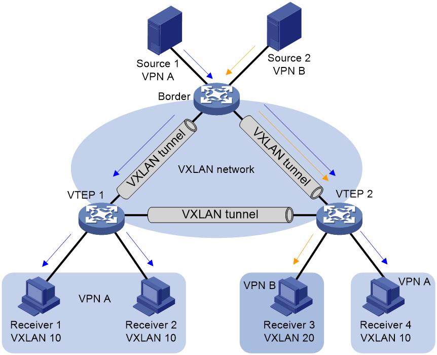
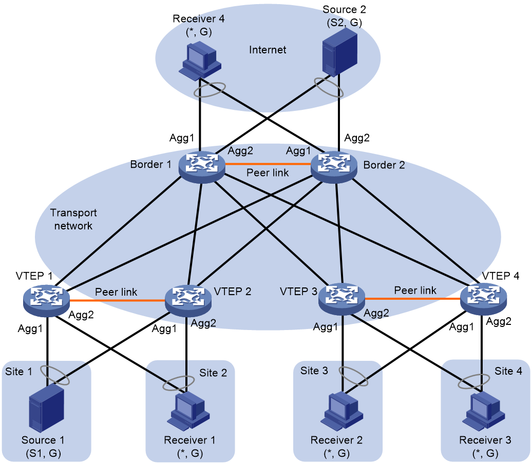
Figure 1 shows a typical MVXLAN network that uses ingress replication. In the network, the border device is attached to multiple sources, and the VTEPs are attached to multicast receivers. VXLAN tunnels are manually established between the border device and the VTEPs and assigned to VXLANs. When receiving multicast packets, the border device identifies the VPN instance to which the packets belong and forwards them to the VTEPs configured with the VPN instance. Then, the VTEPs forward the multicast packets to the attached multicast receivers in the VPN instance.
Figure 1 Ingress replication MVXLAN network model
Working mechanism
Ingress replication MVXLAN requires the following configuration on the border device and VTEPs:
· On the border device, create VSI interfaces, associate them with VPN instances, and enable IGMP on the VSI interfaces.
· On the border device, associate the multicast source-facing interfaces with VPN instances.
· On the border device and VTEPs, enable IGMP snooping on VSIs.
The border device and VTEPs learn multicast forwarding entries as follows:
1. On the border device, VSI interfaces broadcast IGMP queries in their respective VXLANs after they are enabled with IGMP.
2. The VTEPs mark the VXLAN tunnel interfaces where the IGMP queries are received as IGMP snooping router ports, remove VXLAN encapsulation from the IGMP queries, and forward them to local hosts.
3. Multicast receivers reply with IGMP membership reports.
4. The VTEPs mark the ACs where the IGMP membership reports are received as IGMP snooping member ports and forward the reports to the border device through VXLAN tunnels.
5. The border device receives the IGMP membership reports on a VXLAN tunnel interface and marks the VXLAN tunnel interface as an IGMP snooping member port.
Having learned multicast forwarding entries, the border device and VTEPs forward multicast traffic as follows:
1. When receiving multicast packets, the border device identifies their VPN instance by the incoming interface and forwards them based on the multicast forwarding table of the VPN instance.
2. If the traffic outgoing interface is a VSI interface, the border device forwards the multicast packets through the IGMP snooping member ports in the VXLAN associated with the VSI interface. The IGMP snooping member ports are VXLAN tunnel interfaces.
3. The VTEPs decapsulate the multicast packets and forward them out of member ports to multicast receivers.
MDT MVXLAN
On the public network, MVXLAN multicast traffic is forwarded along an MDT rooted at the multicast source-side VTEP to leaf receiver-side VTEPs through unidirectional MVXLAN tunnels. MDT-based transmission ensures that multicast traffic is forwarded along optimal paths.
Benefits
MDT MVXLAN provides the following benefits:
· On-demand multicast forwarding—Creates multicast distribution trees and manages multicast group members by using BGP EVPN routes and PIM.
· Inter-VXLAN multicast forwarding—Uses distributed EVPN gateways to forward Layer 3 multicast traffic between VXLANs.
Network model
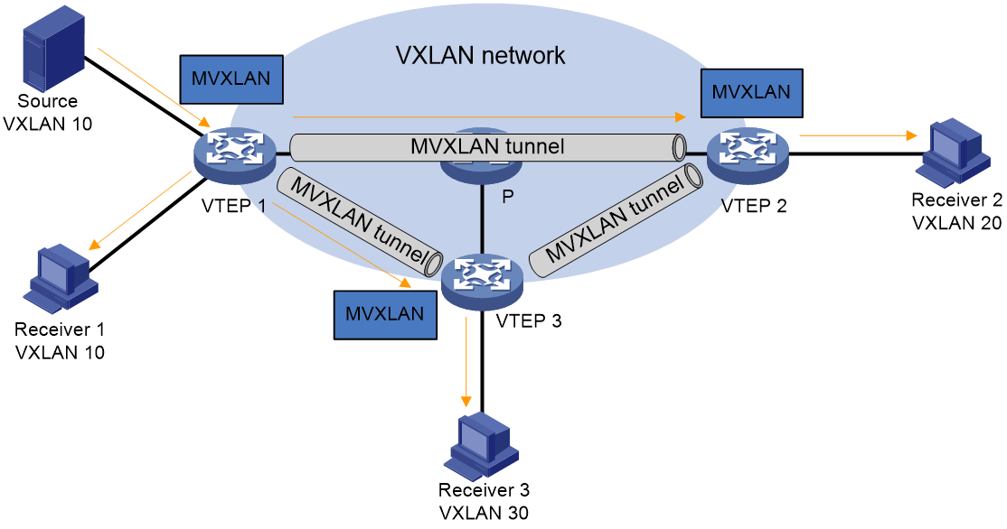
As shown in Figure 2, distributed EVPN gateways are collocated with the VTEPs, and MVXLANs are created on the VTEPs to direct multicast traffic forwarding. When receiving multicast packets, a VTEP forwards them through ACs and MVXLAN tunnels to multicast receivers.
For more information about VTEPs, VSIs, and VXLANs, see VXLAN Configuration Guide. For more information about EVPN configuration, see "Configuring EVPN."
Figure 2 MDT MVXLAN network model
Basic concepts
The following are the basic concepts in MVXLAN:
· MDT—An MDT is a multicast distribution tree constructed by all VTEPs in the same MVXLAN. MDTs include the default MDT and the data MDT.
· Default group—A default group is a unique multicast address assigned to each MVXLAN on the public network. It is the unique identifier of an MVXLAN on the public network and helps build the default MDT for an MVXLAN on the public network. Packets of the private multicast groups in an MVXLAN are encapsulated into packets of the default group before they are transmitted on the public network.
· Default MDT—A default MDT uses a default group address as its group address. The default MDT of an MVXLAN is uniquely identified by the default group and transmits all private multicast packets of the MVXLAN. A default MDT is automatically created after the default group is specified and will always exist on the public network, regardless of whether multicast services exist on the public network or MVXLAN.
· Data group—An MVXLAN is assigned a unique data group for MDT switchover. If you use an ACL to match the multicast traffic of an MVXLAN, the ingress VTEP selects a least used address from the data group range to encapsulate the matching multicast packets of the MVXLAN. Other VTEPs are notified to use the address to forward the matching traffic of the MVXLAN. This initiates the switchover to the data MDT.
· Data MDT—A data MDT is an MDT that uses a data group as it group address. At MDT switchover, VTEPs with downstream receivers join a data group to build a data MDT. The ingress VTEP forwards the encapsulated MVXLAN multicast traffic along the data MDT over the public network.
MP-BGP extension for MVXLAN
To support MVXLAN, MP-BGP introduces the following routes for creating MDTs under the EVPN address family:
· Supplementary broadcast domain selective multicast Ethernet tag (SBD-SMET) route—Contains private multicast source address and private multicast group address information. A receiver-side VTEP uses the SBD-SMET route to advertise its interest in a specific (*, G) or (S, G). An SBD-SMET route carries the RD configured in VPN instance view and export targets configured in VPN instance IPv4 or IPv6 address family view.
· Selective provider multicast service interface route—Also known as S-PMSI A-D route. An S-PMSI A-D route contains the private multicast source address, private multicast group address, default or data group address, and MVXLAN source interface address. S-PMSI A-D routes are used by the multicast source-side VTEP and its BGP peers to establish the default MDT and switch traffic from the default MDT to a data MDT. An S-PMSI A-D route carries the RD configured in VPN instance view and export targets configured in VPN instance IPv4 or IPv6 address family view.
Automatic MVXLAN tunnel establishment and assignment
In an MVXLAN network, VTEPs automatically establish MVXLAN tunnels and assign them to MVXLANs to forward Layer 3 multicast traffic. The tunnel source is the MVXLAN source interface address, and the tunnel destination is the default or data group address. An MVXLAN tunnel is a unidirectional tunnel from the multicast source-side VTEP to a multicast receiver-side VTEP.
Default MDT establishment
The multicast routing protocol running on the public network can be PIM-SM or PIM-SSM. The process of creating a default MDT is the same in these PIM modes. All VTEPs in an MVXLAN join the default MDT of the MVXLAN. The private multicast packets of the MVXLAN are forwarded along the default MDT to the VTEPs, no matter whether the site attached to a VTEP contains receivers.
Figure 3 Default MDT establishment in a PIM-SM network
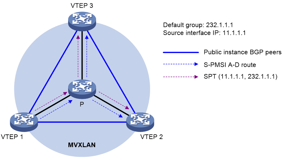
As shown in Figure 3, PIM-SM runs on the public network, and MVXLAN is configured on all VTEPs. The process for establishing a default MDT is as follows:
1. VTEP 1 sends an S-PMSI A-D route that contains (*, *) to VTEP 2 and VTEP 3.
2. VTEP 2 and VTEP 3 receive the route and join a multicast group according to the PMSI tunnel attribute of the route. The PMSI tunnel attribute contains the following information:
¡ The multicast source is the IP address of the MVXLAN source interface on VTEP 1.
¡ The multicast group is the default group configured on VTEP 1.
3. Multicast forwarding entries are created on each device along the paths on the public network, and a shortest path tree (SPT) with VTEP 1 as the root and VTEP 2 and VTEP 3 as leaves is created. The SPT is the default MDT.
Default MDT-based transmission
After the default MDT is established, the multicast source sends the private multicast traffic to the receivers in each site along the default MDT. The private multicast packets are encapsulated into public multicast packets on the local VTEP and transmitted along the default MDT. Then, they are decapsulated on the remote VTEPs and transmitted in remote VXLAN sites.
Figure 4 Multicast data packet transmission
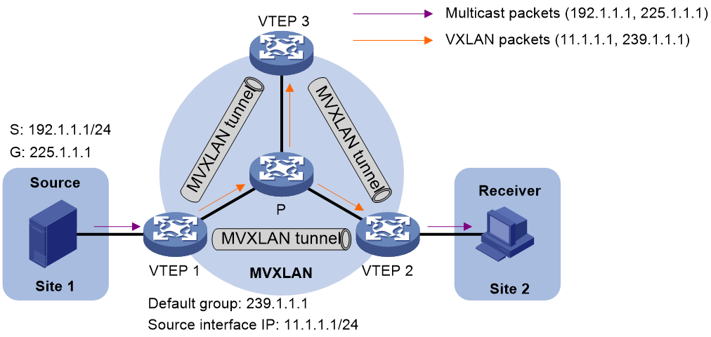
As shown in Figure 4, PIM-SM runs on the public network, the multicast source is attached to VTEP 1, and the multicast receiver is attached to VTEP 2. The multicast forwarding process is as follows:
1. The multicast source sends private multicast packets (192.1.1.1, 225.1.1.1) to VTEP 1.
2. VTEP 1 creates a multicast forwarding entry for (192.1.1.1, 225.1.1.1).
3. VTEP 1 processes the packets based on whether the receiver has joined the private multicast group:
¡ If the receiver has sent an IGMP join message to VTEP 2, VTEP 1 has an SBD-SMET route sent by VTEP 1 that contains (*, G). VTEP 1 adds VXLAN encapsulation to the packets according to the route and forwards them to VTEP 2 and VTEP 3 along the default MDT. In the outer IP header of the VXLAN packets, the source IP address is the IP address of the MVXLAN source interface, and the destination IP address is the default group address.
¡ If no receiver exists, VTEP 1 drops the packets.
4. VTEP 2 decapsulates the VXLAN packets and forwards the private multicast packets to the receiver.
5. VTEP 3 decapsulates the VXLAN packets and drops the private multicast packets because no local receiver exists.
MDT switchover
An MVXLAN can use the default MDT or a data MDT for multicast traffic forwarding. The default MDT is uniquely identified by the default group, and a data MDT is uniquely identified by a data group. Each default group is associated with a data group range.
Switching from the default MDT to a data MDT
When a multicast packet of an MVXLAN is transmitted through the default MDT on the public network, the packet is forwarded to all VTEPs configured with the VPN instance of the MVXLAN. This occurs whether or not any active receivers exist in the sites attached to the VTEPs. When the rate of the multicast traffic of that MVXLAN is high, multicast traffic might be flooded on the public network. This increases the bandwidth use and brings extra burden on the VTEPs.
To optimize multicast transmission, the MDT-based MVXLAN solution introduces a dedicated data MDT. The data MDT is built between the VTEPs that are attached to MVXLAN multicast receivers and multicast sources. When specific network criteria are met, multicast traffic is switched from the default MDT to the data MDT.
A switchover from the default MDT to the data MDT is initiated as follows:
1. Private multicast traffic passes the ACL rule filtering for default MDT to data MDT switchover.
2. The source-side VTEP selects a least-used address from the data group range and sends an S-PMSI A-D route to all the other VTEPs down the default MDT. This route contains the private multicast source address, private multicast group address, IP address of the MVXLAN source interface, and data group address.
3. Each VTEP that receives the route examines whether it has receivers of that private multicast stream.
If so, it joins the data MDT rooted at the source-side VTEP. Otherwise, it caches the route and will join the data MDT when it has attached receivers.
4. After sending the S-PMSI A-D route, the source-side VTEP starts the data-delay timer. When the timer expires, the source-side VTEP uses the data group address to encapsulate the private multicast traffic. The multicast traffic is then forwarded down the data MDT.
5. After the multicast traffic is switched from the default MDT to the data MDT, a downstream VTEP can leave the data MDT by sending a PIM prune message if it no longer has active receivers attached to it.
Switching from the data MDT to the default MDT
After the MXVLAN multicast traffic is switched to the data MDT, the multicast traffic conditions might change and no longer meet the switchover criterion. In this case, the source-side VTEP initiates a backward MDT switchover process when any of the following criteria are met:
· The associated data group range is changed, and the data group address for encapsulating the MVXLAN multicast traffic is not in the new address range.
· The ACL rule for controlling the switchover from the default MDT to the data MDT has changed, and the MVXLAN multicast traffic fails to pass the new ACL rule.
M-LAG in MVXLAN
Overview
As shown in Figure 5, you can use multichassis link aggregation (M-LAG) to virtualize two VTEPs or border devices into an M-LAG system to prevent single points of failure from interrupting traffic. The VTEPs or border devices can have both multicast sources and receivers attached. For more information about M-LAG, see Layer 2—LAN Switching Configuration Guide.
Mechanisms
In an M-LAG system, the M-LAG member devices synchronize multicast traffic and multicast join requests (IGMP membership reports or PIM join messages) over the peer link to maintain consistency in multicast source and receiver information. When one M-LAG member device fails or its uplink or downlink fails, the other M-LAG member device forwards all multicast traffic to avoid traffic interruption.
As shown in Figure 5, the M-LAG system formed by VTEP 1 and VTEP 2 operates as follows:
1. VTEP 1 and VTEP 2 set up MVXLAN tunnels with the other devices on the network. The MVXLAN tunnels use the virtual VTEP address as the multicast source and the default group address as the destination address.
2. When receiving the multicast join requests sent by the multicast receivers on aggregate interface 2, VTEP 1 sends the requests over the peer link to VTEP 2.
3. Both VTEP 1 and VTEP 2 create multicast forwarding entries for the multicast join requests and send SBD-SMET routes to the multicast source-side VTEP.
4. When receiving the multicast traffic sent by the multicast source on aggregate interface 1, VTEP 1 sends the multicast traffic over the peer link to VTEP 2.
5. VTEP 1 and VTEP 2 forward the multicast traffic according to the following rules:
¡ The M-LAG member device with an odd M-LAG system number forwards traffic destined for odd multicast group addresses.
¡ The M-LAG member device with an even M-LAG system number forwards traffic destined for even multicast group addresses.
¡ When one M-LAG member device fails, the other M-LAG member device forwards all multicast traffic.
6. If the requirements are met for switching traffic from the default MDT to a data MDT, the primary M-LAG member device selects a target data MDT and advertises the data MDT to the secondary M-LAG member device through an SBD-SMET route.
7. The secondary M-LAG member device acts as follows:
¡ If the data group exists on the device, the device uses that data group for multicast forwarding.
¡ If the data group does not exist or the device does not receive the SBD-SMET route, the device selects a local data group.
Layer 3 multicast data failover through the peer link
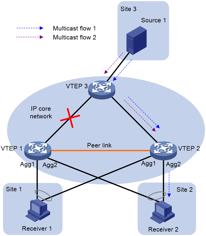
As shown in Figure 6, in the M-LAG in MVXLAN scenario, multicast traffic on VTEP 2 cannot be synchronized to VTEP 1 over the peer link when the uplink of VTEP 1 fails. As defined by the odd/even traffic forwarding rules, VTEP 2 can forward only multicast data destined for odd or even multicast group addresses to the receiver. This practice can cause forwarding exceptions of multicast data destined for even or odd multicast group addresses.
Figure 6 Forwarding failures of some multicast traffic when the uplink fails
To address the previously-mentioned issue, you can specify a reserved VLAN for the peer link on VTEP 1 and VTEP 2 to add the peer-link interfaces to the reserved VLAN. With a reserved VLAN configured, the peer link can be used as the failover link for multicast data. As shown in Figure 7, if the outgoing interface corresponding to the (S, G) entry on VTEP 2 is the reserved VLAN interface, the peer-link interfaces will be added to the outgoing interface list of the (S, G) entry. Multicast data on VTEP 2 will be forwarded to VTEP 1 over the peer link. For more information about reserved VLAN configuration for the peer link, see M-LAG configuration in Layer 2—LAN Switching Configuration Guide.
Figure 7 Peer link used as the failover link for Layer 3 multicast data

Configuring ingress replication MVXLAN
Restrictions and guidelines: Multicast source location
You can attach a multicast source only to a border device in an ingress replication MVXLAN network.
Before you configure multicast features on a VSI interface, assign a primary IP address to the VSI interface.
Ingress replication MVXLAN tasks at a glance
To configure ingress replication MVXLAN, perform the following tasks:
1. Configuring VXLAN
a. Configuring a VXLAN on a VSI
b. Configuring a VXLAN tunnel
c. Manually assigning VXLAN tunnels to a VXLAN
d. Assigning customer frames to a VSI
For more information about VXLAN configuration, see VXLAN Configuration Guide.
2. Configuring IGMP and IGMP snooping
a. Enabling IGMP on a VSI interface on a border device
b. Enabling IGMP snooping on a VSI on a border device or VTEP
For more information about IGMP and IGMP snooping configuration, see IP Multicast Configuration Guide.
3. Configuring a VPN instance
a. Creating a VPN instance
b. Associating a VSI interface with a multicast source-facing interface on a border device
For more information about VPN instance configuration, see MPLS L3VPN configuration in MPLS Configuration Guide.
4. Configuring MVXLAN
a. Enabling IP multicast routing for a VPN instance
c. Configuring a VSI interface as a distributed designated router interface
You must perform this task on a VTEP if the VTEP acts as a distributed VXLAN IP gateway.
Enabling IP multicast routing for a VPN instance
1. Enter system view.
system-view
2. Enable IP multicast routing for a VPN instance and enter MRIB view.
multicast routing vpn-instance instance-name
By default, IP multicast routing is disabled for VPN instances.
For more information about this command, see multicast routing and forwarding commands in IP Multicast Command Reference.
Creating an MVXLAN
About this task
You can create one or multiple ingress replication MVXLANs on a VTEP to provide services for different VPN instances and the public instance.
Creating an MVXLAN for a VPN instance
1. Enter system view.
system-view
2. Create an ingress replication MVXLAN and enter MVXLAN view.
multicast-vpn vxlan vpn-instance instance-name mode ingress-replication
3. Create the MVXLAN IPv4 address family and enter its view.
address-family ipv4
Creating an MVXLAN for the public instance
1. Enter system view.
system-view
2. Create an ingress replication MVXLAN and enter MVXLAN view.
multicast-vpn vxlan public-instance mode ingress-replication
3. Create the MVXLAN IPv4 address family and enter its view.
address-family ipv4
Configuring a VSI interface as a distributed designated router interface
About this task
On the VTEPs configured with MVXLAN, you must specify the VSI interfaces that act as distributed EVPN gateways as distributed designated router interfaces. This operation ensures that a distributed EVPN gateway can forward multicast traffic to the local site.
Procedure
1. Enter system view.
system-view
2. Enter VSI interface view.
interface vsi-interface interface-number
3. Configure the VSI interface as a distributed designated router interface.
pim distributed-dr
By default, a VSI interface is not a distributed designated router interface.
For more information about this command, see PIM commands in IP Multicast Command Reference.
Ingress replication MVXLAN configuration examples
Example: Configuring an ingress replication MVXLAN
Network configuration
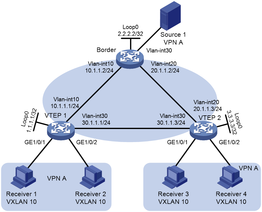
As shown in Figure 8, the border device is attached to a multicast source in VPN A. Configure an ingress replication MVXLAN to forward the multicast traffic from the source to the receivers, and configure VTEP 1 as a centralized VXLAN IP gateway.
Procedure
1. Configure IP addresses and unicast routing settings:
# Assign IP addresses to interfaces, as shown in Figure 8. (Details not shown.)
# Configure OSPF on the border device and VTEPs for them to reach one another. (Details not shown.)
2. Configure the border device:
# Enable L2VPN and IGMP snooping.
<Border> system-view
[Border] l2vpn enable
[Border] igmp-snooping
[Border-igmp-snooping] quit
# Set up VXLAN tunnels to the VTEPs.
[Border] interface tunnel 1 mode vxlan
[Border-Tunnel1] source 2.2.2.2
[Border-Tunnel1] destination 1.1.1.1
[Border-Tunnel1] quit
[Border] interface tunnel 2 mode vxlan
[Border-Tunnel2] source 2.2.2.2
[Border-Tunnel2] destination 3.3.3.3
[Border-Tunnel2] quit
# Create VSI vpna and VXLAN 10, and enable IGMP snooping on VSI vpna.
[Border] vsi vpna
[Border-vsi-vpna] igmp-snooping enable
[Border-vsi-vpna] vxlan 10
# Assign Tunnel 1 and Tunnel 2 to VXLAN 10.
[Border-vsi-vpna-vxlan-10] tunnel 1
[Border-vsi-vpna-vxlan-10] tunnel 2
[Border-vsi-vpna-vxlan-10] quit
[Border-vsi-vpna] quit
# Create VPN instance vpna.
[Border] ip vpn-instance vpna
[Border-vpn-instance-vpna] quit
# Enable IP multicast routing.
[Border] multicast routing vpn-instance vpna
[Border-mrib] quit
# Configure VSI-interface 1, associate it with VPN instance vpna, and enable IGMP on it.
[Border] interface vsi-interface 1
[Border-Vsi-interface] ip binding vpn-instance vpna
[Border-Vsi-interface] ip address 100.1.1.2 255.255.255.0
[Border-Vsi-interface] igmp enable
[Border-Vsi-interface] quit
# Specify VSI-interface 1 as the gateway interface for VSI vpna.
[Border] vsi vpna
[Border-vsi-vpna] gateway vsi-interface 1
[Border-vsi-vpna] quit
# Associate multicast source-facing interface VLAN-interface 30 with VPN instance vpna, and enable PIM SM on VLAN-interface 30.
[Border] interface vlan-interface 30
[Border-Vlan-interface30] ip binding vpn-instance vpna
[Border-Vlan-interface30] ip address 100.2.2.2 255.255.255.0
[Border-Vlan-interface30] pim sm
[Border-Vlan-interface30] quit
# Create an ingress replication MVXLAN, and create the MVXLAN IPv4 address family and enter its view.
[Border] multicast-vpn vxlan vpn-instance vpna mode ingress-replication
[Border-mvxlan-vpna] address-family ipv4
[Border-mvxlan-vpna] quit
3. Configure VTEP 1:
# Enable L2VPN and IGMP snooping.
<VTEP1> system-view
[VTEP1] l2vpn enable
[VTEP1] igmp-snooping
[VTEP1-igmp-snooping] quit
# Set up a VXLAN tunnel to the border device.
[VTEP1] interface tunnel 2 mode vxlan
[VTEP1-Tunnel2] source 1.1.1.1
[VTEP1-Tunnel2] destination 2.2.2.2
[VTEP1-Tunnel2] quit
# Create VSI vpna and VXLAN 10, and enable IGMP snooping on VSI vpna.
[VTEP1] vsi vpna
[VTEP1-vsi-vpna] igmp-snooping enable
[VTEP1-vsi-vpna] vxlan 10
# Assign Tunnel 2 to VXLAN 10.
[VTEP1-vsi-vpna-vxlan-10] tunnel 2
[VTEP1-vsi-vpna-vxlan-10] quit
[VTEP1-vsi-vpna] quit
# On GigabitEthernet 1/0/1 and GigabitEthernet 1/0/2, create Ethernet service instance 1000 to match VLAN 2 and map Ethernet service instance 1000 to VSI vpna.
[VTEP1] interface gigabitethernet 1/0/1
[VTEP1-GigabitEthernet1/0/1] service-instance 1000
[VTEP1-GigabitEthernet1/0/1-srv1000] encapsulation s-vid 2
[VTEP1-GigabitEthernet1/0/1-srv1000] xconnect vsi vpna
[VTEP1-GigabitEthernet1/0/1-srv1000] quit
[VTEP1-GigabitEthernet1/0/1] quit
[VTEP1] interface gigabitethernet 1/0/2
[VTEP1-GigabitEthernet1/0/2] service-instance 1000
[VTEP1-GigabitEthernet1/0/2-srv1000] encapsulation s-vid 2
[VTEP1-GigabitEthernet1/0/2-srv1000] xconnect vsi vpna
[VTEP1-GigabitEthernet1/0/2-srv1000] quit
[VTEP1-GigabitEthernet1/0/2] quit
4. Configure VTEP 2:
# Enable L2VPN and IGMP snooping.
<VTEP2> system-view
[VTEP2] l2vpn enable
[VTEP2] igmp-snooping
[VTEP2-igmp-snooping] quit
# Set up a VXLAN tunnel to the border device.
[VTEP2] interface tunnel 2 mode vxlan
[VTEP2-Tunnel2] source 3.3.3.3
[VTEP2-Tunnel2] destination 2.2.2.2
[VTEP2-Tunnel2] quit
# Create VSI vpna and VXLAN 10, and enable IGMP snooping on VSI vpna.
[VTEP2] vsi vpna
[VTEP2-vsi-vpna] igmp-snooping enable
[VTEP2-vsi-vpna] vxlan 10
# Assign Tunnel 2 to VXLAN 10.
[VTEP2-vsi-vpna-vxlan-10] tunnel 2
[VTEP2-vsi-vpna-vxlan-10] quit
[VTEP2-vsi-vpna] quit
# On GigabitEthernet 1/0/1 and GigabitEthernet 1/0/2, create Ethernet service instance 1000 to match VLAN 2 and map Ethernet service instance 1000 to VSI vpna.
[VTEP2] interface gigabitethernet 1/0/1
[VTEP2-GigabitEthernet1/0/1] service-instance 1000
[VTEP2-GigabitEthernet1/0/1-srv1000] encapsulation s-vid 2
[VTEP2-GigabitEthernet1/0/1-srv1000] xconnect vsi vpna
[VTEP2-GigabitEthernet1/0/1-srv1000] quit
[VTEP2-GigabitEthernet1/0/1] quit
[VTEP2] interface gigabitethernet 1/0/2
[VTEP2-GigabitEthernet1/0/2] service-instance 1000
[VTEP2-GigabitEthernet1/0/2-srv1000] encapsulation s-vid 2
[VTEP2-GigabitEthernet1/0/2-srv1000] xconnect vsi vpna
[VTEP2-GigabitEthernet1/0/2-srv1000] quit
[VTEP2-GigabitEthernet1/0/2] quit
Verifying the configuration
1. Verify the MVXLAN settings on the border device:
# Verify that the VXLAN tunnel interfaces are up on the border device.
[Border] display interface tunnel 1
Tunnel1
Current state: UP
Line protocol state: UP
Description: Tunnel2 Interface
Bandwidth: 64 kbps
Maximum transmission unit: 1464
Internet protocol processing: Disabled
Output queue - Urgent queuing: Size/Length/Discards 0/100/0
Output queue - Protocol queuing: Size/Length/Discards 0/500/0
Output queue - FIFO queuing: Size/Length/Discards 0/75/0
Last clearing of counters: Never
Tunnel source 2.2.2.2, destination 1.1.1.1
Tunnel protocol/transport UDP_VXLAN/IP
Last 300 seconds input rate: 0 bytes/sec, 0 bits/sec, 0 packets/sec
Last 300 seconds output rate: 0 bytes/sec, 0 bits/sec, 0 packets/sec
Input: 0 packets, 0 bytes, 0 drops
Output: 0 packets, 0 bytes, 0 drops
# Verify that VSI-interface 1 is up.
[Border] display interface vsi-interface brief
Brief information on interfaces in route mode:
Link: ADM - administratively down; Stby - standby
Protocol: (s) - spoofing
Interface Link Protocol Primary IP Description
Vsi1 UP UP 10.1.1.1
# Verify that the border device has multicast routing entries.
[Border] display pim vpn-instance vpna routing-table
Total 17 (*, G) entries; 18 (S, G) entries
(10.1.2.99, 225.0.1.1)
RP: 10.1.2.88 (local)
Protocol: pim-sm, Flag: SPT 2MSDP LOC ACT 2MVPN
UpTime: 21:24:27
Upstream interface: Vlan-interface30
Upstream neighbor: NULL
RPF prime neighbor: NULL
Downstream interface information:
Total number of downstream interfaces: 1
1: Vsi-interface1
Protocol: pim-sm, UpTime: 07:08:26, Expires: -
2. Verify the MVXLAN settings on VTEP 1:
# Verify that the interfaces that host ACs are member ports.
[VTEP1] display igmp-snooping group
Total 1 entries.
VSI vpna: Total 1 entries.
(0.0.0.0, 225.0.1.1)
Host ports (1 in total):
GE1/0/1 (Link ID 0) (00:04:20)
GE1/0/2 (Link ID 1) (00:04:20)
# Verify that Tunnel 2 is a router port.
[VTEP1] display igmp-snooping router-port
VSI vpna:
Router ports (1 in total):
Tun2 (VXLAN ID 10) (00:03:23)
3. Verify that the multicast receivers can receive the multicast traffic sent by the multicast source. (Details not shown.)
Configuring MDT-based MVXLAN
MDT-based MVXLAN tasks at a glance
To configure MDT-based MVXLAN, perform the following tasks:
1. Configuring EVPN
a. Configuring a VXLAN on a VSI
b. Mapping ACs to a VSI
c. Configuring an EVPN instance
d. Configuring BGP to advertise BGP EVPN routes
e. Configuring a distributed EVPN gateway
For more information about EVPN configuration, see "Configuring EVPN."
2. Configuring IGMP and IGMP snooping
a. Enabling IGMP on a VSI interface
b. Enabling IGMP proxying on a VSI interface
c. Enabling IGMP snooping
d. Configuring IGMP snooping proxying
For more information about IGMP and IGMP snooping configuration, see IP Multicast Configuration Guide.
3. Configuring PIM on the transport-facing interfaces of VTEPs
Choose one of the following tasks:
¡ Configuring PIM-SM
¡ Configuring PIM-SSM
For more information about PIM configuration, see IP Multicast Configuration Guide.
4. Configuring MVXLAN
a. Enabling IP multicast routing for a VPN instance
c. Configuring a default group
d. Specifying the MVXLAN source interface
e. Configuring MDT switchover parameters
f. Configuring a VSI interface as a distributed designated router interface
g. (Optional.) Configuring an MVXLAN extranet RPF selection policy
h. (Optional.) Configuring M-LAG in MVXLAN
Restrictions: IGMP proxying configuration
When you configure IGMP proxying for an MDT-based MVXLAN, follow these restrictions and guidelines:
· You must enable IGMP proxying on all VTEPs and EDs. Do not enable IGMP proxying on only some of the VTEPs or EDs in the MVXLAN.
· IGMPv1 is not supported.
· If multicast receivers send IGMP membership reports that carry (*, G) information, make sure all multicast sources that send traffic to the related multicast group are attached to the same VTEP. This restriction frequents frequent changes of outgoing interfaces in multicast forwarding entries from affecting traffic forwarding.
Enabling IP multicast routing for a VPN instance
Procedure (IPv4)
1. Enter system view.
system-view
2. Enable IPv4 multicast routing for a VPN instance and enter MRIB view.
multicast routing vpn-instance instance-name
By default, IPv4 multicast routing is disabled for VPN instances.
For more information about the commands, see multicast routing and forwarding commands in IP Multicast Command Reference.
Procedure (IPv6)
1. Enter system view.
system-view
2. Enable IPv6 multicast routing for a VPN instance and enter MRIB view.
ipv6 multicast routing vpn-instance instance-name
By default, IPv6 multicast routing is disabled for VPN instances.
For more information about the commands, see IPv6 multicast routing and forwarding commands in IP Multicast Command Reference.
Creating an MVXLAN
About this task
You can create one or multiple MDT-based MVXLANs on a VTEP to provide services for different VPN instances and the public instance.
Restrictions and guidelines
If a multicast source is attached to one VTEP or border device and the multicast receivers are attached to another VTEP or border device, MVXLAN cannot forward multicast traffic in the public instance.
Creating an MVXLAN for a VPN instance
1. Enter system view.
system-view
2. Create an MDT-based MVXLAN and enter MVXLAN view.
multicast-vpn vxlan vpn-instance instance-name mode mdt
Creating an MVXLAN for the public instance
1. Enter system view.
system-view
2. Create an MDT-based MVXLAN and enter MVXLAN view.
multicast-vpn vxlan public-instance mode mdt
Configuring a default group
About this task
When adding VXLAN encapsulation to private multicast packets, the VTEP uses the default group as the destination IP address in the outer IP header.
Restrictions and guidelines
The default group address of an MVXLAN must be unique among MVXLANs, and it cannot be the same as a data group address of any MVXLAN.
For an MVXLAN that transmits both IPv4 and IPv6 multicast packets, you must specify the same default group in MVXLAN IPv4 address family view and IPv6 address family view, and the data group ranges in the two views cannot overlap.
Procedure
1. Enter system view.
system-view
2. Enter MVXLAN view.
multicast-vpn vxlan vpn-instance instance-name mode mdt
3. Create the MVXLAN IPv4 or IPv6 address family and enter its view.
IPv4:
address-family ipv4
IPv6:
address-family ipv6
4. Configure the default group.
default-group group-address
By default, no default group exists.
Specifying the MVXLAN source interface
About this task
When adding VXLAN encapsulation to private multicast packets, the VTEP uses the IP address of the MVXLAN source interface as the source IP address in the outer IP header.
Restrictions and guidelines
You must configure the same MVXLAN source interface for all MVXLAN instances on the device.
For the VTEP to obtain correct routing information, you must specify the interface used for establishing BGP peer relationships as the MVXLAN source interface.
Procedure
1. Enter system view.
system-view
2. Enter MVXLAN view.
multicast-vpn vxlan vpn-instance instance-name mode mdt
3. Enter MVXLAN IPv4 or IPv6 address family view.
IPv4:
address-family ipv4
IPv6:
address-family ipv6
4. Specify the MVXLAN source interface.
source interface-type interface-number
By default, no MVXLAN source interface is specified.
Configuring MDT switchover parameters
About this task
To avoid frequent switching of multicast traffic between the default MDT and a data MDT, set the data-delay period. The data-delay period enables the device to perform MDT switchover after a delay.
Restrictions and guidelines
On a VTEP, the data group range of an MVXLAN cannot include the default group or data groups of any other MVXLAN.
For an MVXLAN that transmits both IPv4 and IPv6 multicast packets, you must specify the same default group in MVXLAN IPv4 address family view and IPv6 address family view, and the data group ranges in the two views cannot overlap.
All VPN instances share the data group resources. As a best practice to avoid data group resource exhaustion, specify a reasonable data group range for a VPN instance.
Procedure
1. Enter system view.
system-view
2. Enter MVXLAN view.
multicast-vpn vxlan vpn-instance instance-name mode mdt
3. Enter MVXLAN IPv4 or IPv6 address family view.
IPv4:
address-family ipv4
IPv6:
address-family ipv6
4. Configure the data group range and the switchover criteria.
data-group group-address { mask-length | mask } [ acl acl-number | name acl-name ]
By default, no data group range exists, and the default MDT to data MDT switchover never occurs.
5. Set the data-delay period.
data-delay delay
By default, the data-delay period is 3 seconds.
Configuring a VSI interface as a distributed designated router interface
About this task
On the VTEPs configured with MVXLAN, you must specify the VSI interfaces that act as distributed EVPN gateways as distributed designated router interfaces. This operation ensures that a distributed EVPN gateway can forward multicast traffic to the local site.
Procedure
1. Enter system view.
system-view
2. Enter VSI interface view.
interface vsi-interface interface-number
3. Configure the VSI interface as a distributed designated router interface.
pim distributed-dr
A VSI instance is not a distributed designated router interface.
For more information about this command, see PIM commands in IP Multicast Command Reference.
Configuring an MVXLAN extranet RPF selection policy
About this task
MVXLAN extranet RPF routing policies are used for multicast transmission when multicast sources and receivers are located in different VPNs.
· L3 VXLAN ID-based RPF selection policy—A policy of this kind specifies the L3 VXLAN ID of the VPN instance where a multicast source resides, a multicast source address, and a multicast group address.
A multicast source-side VTEP matches the L3 VXLAN ID, multicast source address, and multicast group address in multicast packets with RPF selection policies. If a match is found, the VTEP forwards the packets to the receiver VPN instance.
With RPF selection policies configured, a multicast receiver-side VTEP forwards multicast traffic as follows:
a. Removes the VXLAN header added by the multicast source-side VTEP from received multicast packets. The VXLAN header includes the L3 VXLAN ID of the source VPN instance.
b. Matches the L3 VXLAN ID, multicast source address, and multicast group address of the packets with RPF selection policies.
c. Forwards the packets in the receiver VPN instance if a match is found.
· VPN instance-based RPF selection policy—A policy of this kind specifies the VPN instance where a multicast source resides, a multicast source address, and a multicast group address.
A multicast source-side VTEP matches the VPN instance, multicast source address, and multicast group address in multicast packets with RPF selection policies. If a match is found, the VTEP forwards the packets to the receiver VPN instance.
With RPF selection policies configured, a multicast receiver-side VTEP forwards multicast traffic as follows:
d. Removes the VXLAN header added by the multicast source-side VTEP from received multicast packets. The VXLAN header includes the L3 VXLAN ID of the source VPN instance.
e. Matches the VPN instance, multicast source address, and multicast group address of the packets with RPF selection policies.
f. Forwards the packets in the receiver VPN instance if a match is found.
You can use RPF selection policies on the following networks:
· Asymmetrically configured extranet—The source VPN instance is not configured on the multicast receiver-side VTEP.
¡ On the multicast source-side VTEP, you can configure either L3 VXLAN ID-based or VPN instance-based RPF selection policies.
¡ On the multicast receiver-side VTEP, you can configure only L3 VXLAN ID-based RPF selection policies.
· Symmetrically configured extranet—The source VPN instance is configured on the multicast receiver-side VTEP. You can configure either L3 VXLAN ID-based or VPN instance-based RPF selection policies on the multicast source-side and receiver-side VTEPs.
If some of the multicast receivers reside on the public network, specify only the multicast source address and multicast group address in the related RPF selection policies. On the multicast receiver-side VTEP, perform the following tasks for the VTEP to forward multicast traffic in both the receiver VPN instance and the public network:
2. Assign an L3 VXLAN ID to the public instance.
3. Configure an RPF selection policy that does not include an L3 VXLAN ID or VPN instance for the receiver VPN instance.
Restrictions and guidelines
MVXLAN does not support redirecting the public multicast traffic received by a VSI interface to receiver VPNs based on an L3 VXLAN ID-based RPF selection policy.
The PIM mode in the source VPN instance and the receiver VPN instance must be the same. Only PIM-SM and PIM-SSM are supported.
When you use PIM-SM, use one of the following schemes as a best practice:
· Specifying only the multicast source address—Configure two RPF selection policies as follows:
¡ In one policy, configure the multicast source address as the RP address of the multicast group that requires inter-VPN transmission.
¡ In the other policy, specify the multicast source address of the source VPN instance.
If multiple multicast groups require inter-VPN transmission, configure a dedicated RP for the multicast groups and specify the multicast source address as the RP address in RPF selection policies.
· Specifying only the multicast group address—Configure one RPF selection policy that specifies the multicast group address of the source VPN instance.
When you use PIM-SSM, configure one RPF selection policy that contains both the multicast source address and multicast group address as a best practice.
Multicast packets can only be forwarded between two VPNs. The receiver VPN instance cannot also be the source VPN instance.
You cannot specify both an L3 VXLAN ID and an MPLS L3VPN instance for a multicast source address and multicast group address pair.
· In PIM-SM mode, you can configure one RPF selection policy that specifies an L3 VXLAN ID or VPN instance for a multicast group address.
· In PIM-SSM mode, you can configure one RPF selection policy that specifies an L3 VXLAN ID or VPN instance for a multicast source address and multicast group address pair.
For a receiver VPN instance, you must configure the same types of RPF selection policies for all multicast traffic from the same source VPN instance.
If an IPv4 or IPv6 MVPN extranet RPF selection policy with only the multicast group address specified is configured in the receiver VPN instance, the multicast traffic for the intra-VPN transmission will be interrupted.
Multicast source addresses in different MVXLAN extranet RPF routing policies cannot be the same, but they can overlap. The same restriction applies to the multicast group addresses in different MVXLAN extranet RPF routing policies. If multiple routing policies exist for an (S, G) entry, the device selects the policy in which the multicast group address has the longest mask. If multiple policies have the same mask length, the device selects the policy in which the multicast source address has the longest mask.
Configuring an IPv4 MVXLAN extranet RPF selection policy
1. Enter system view.
system-view
2. Enter MRIB view.
multicast routing [ vpn-instance vpn-instance-name ]
3. Configure an IPv4 MVXLAN extranet RPF selection policy.
multicast extranet select-rpf [ l3-vni vxlan-id | vpn-instance vpn-instance-name ] { source source-address { mask | mask-length } | group group-address { mask | mask-length } } *
Configuring an IPv6 MVXLAN extranet RPF selection policy
1. Enter system view.
system-view
2. Enter IPv6 MRIB view.
ipv6 multicast routing [ vpn-instance vpn-instance-name ]
3. Configure an IPv6 MVXLAN extranet RPF selection policy.
ipv6 multicast extranet select-rpf [ l3-vni vxlan-id | vpn-instance vpn-instance-name ] { group group-address prefix-length | source source-address prefix-length } *
Configuring M-LAG in MVXLAN
About this task
For two VTEPs or border devices to be identified as one device, you must assign the same IP address to the MVXLAN source interfaces on them and specify that IP address as the virtual VTEP address. The devices use the virtual VTEP address as the multicast source address to set up MVXLAN tunnels with other devices.
Restrictions and guidelines
Usage guidelines
To use M-LAG in MVXLAN, follow these restrictions:
· All ACs must be dualhomed to the M-LAG member devices. Singlehomed ACs are not supported.
· The peer link can only be an Ethernet aggregate link.
· You cannot use M-LAG to aggregate the links between two VTEPs or between a VTEP and a border device.
Multicast traffic load sharing
You can use only PIM SM on an M-LAG system. The M-LAG member devices load share multicast traffic based on the multicast destination address. They do not support load sharing based on the multicast source address.
If the peer link fails, each M-LAG member device sets its MVXLAN tunnel source address to the local M-LAG member device address and forwards multicast traffic only through the default group. Instead of load sharing multicast traffic, each M-LAG member device forwards all received multicast traffic. When the peer link recovers, the M-LAG member devices set the MVXLAN tunnel source addresses to the virtual VTEP address. They are able to perform switchover to data groups and load share multicast traffic.
Underlay network traffic
As a best practice to prevent receivers from receiving two copies of multicast traffic when the underlay network traffic enters the VTEP or border device through a VLAN interface, configure the peer link to deny the VLAN of the underlay network traffic.
Relationship with M-LAG in EVPN
If you configure both M-LAG in MVXLAN and M-LAG in EVPN or EVPN-DCI, follow these restrictions and guidelines:
· In addition to M-LAG in MVXLAN configuration, you must also execute the evpn m-lag group command to specify the MVXLAN source interface address as the virtual VTEP address.
· For an MVXLAN, the following settings are in descending order of priority:
¡ The m-lag local setting in MVXLAN address family view. This setting takes effect on a per-MVXLAN basis.
¡ The multicast-vpn vxlan m-lag local setting in system view. This setting takes effect on all MVXLANs.
¡ The evpn m-lag local setting in system view. This setting takes effect on all MVXLANs.
Preprequisites
For M-LAG in MVXLAN to take effect, you must enable both Layer 2 and Layer 3 multicast.
To advertise multiple routes with the same prefix to a peer or peer group, configure the BGP Additional Paths feature on the devices connected to the M-LAG system.
Procedure
1. Enter system view.
system-view
2. Globally specify the IP addresses of the member devices in an M-LAG system.
multicast-vpn vxlan m-lag local local-ipv4-address remote remote-ipv4-address
By default, the IP addresses of the member devices in an M-LAG system are not specified globally.
3. Enter MVXLAN view.
multicast-vpn vxlan vpn-instance instance-name mode mdt
4. Enter MVXLAN IPv4 or IPv6 address family view.
IPv4:
address-family ipv4
IPv6:
address-family ipv6
5. Specify the IP addresses of the member devices in the M-LAG system.
m-lag local local-ipv4-address remote remote-ipv4-address
By default, the IP addresses of the member devices in an M-LAG system are not specified.
6. Specify an MVXLAN source interface to provide the virtual VTEP address.
source interface-type interface-number evpn-m-lag-group
By default, no MVXLAN source interface is specified.
7. (Optional.) Specify a reserved VLAN for the peer link in an M-LAG system.
a. Enter the following commands in sequence to enter VLAN view:
quit
quit
vlan vlan-id
b. Specify the VLAN as the reserved VLAN for the peer link.
m-lag peer-link reserved
By default, no reserved VLAN is specified for the peer link in an M-LAG system.
For more information about this command, see Layer 2—LAN Switching Command Reference.
Display and maintenance commands for MDT-based MVXLAN
Execute display commands in any view.
|
Command |
|
|
Display received IPv4 data group information in an MVXLAN. |
display multicast-vpn vxlan { vpn-instance instance-name | public-instance } data-group receive [ brief | [ active | group group-address | sender source-address | vpn-source-address [ mask { mask-length | mask } ] | vpn-group-address [ mask { mask-length | mask } ] ] * ] |
|
Display sent IPv4 data group information in an MVXLAN. |
display multicast-vpn vxlan { vpn-instance instance-name | public-instance } data-group send [ group group-address | vpn-source-address [ mask { mask-length | mask } ] | vpn-group-address [ mask { mask-length | mask } ] ] * |
|
Display information about IPv4 default groups. |
display multicast-vpn vxlan [ vpn-instance instance-name | public-instance ] default-group { local | remote } |
|
Display received IPv6 data group information in an MVXLAN. |
display multicast-vpn vxlan vpn-instance instance-name ipv6 data-group receive [ brief | [ active | group group-address | sender source-address | vpn-source-address [ prefix-length ] | vpn-group-address [ prefix-length ] ] * ] |
|
Display sent IPv6 data group information in an MVXLAN. |
display multicast-vpn vxlan vpn-instance instance-name ipv6 data-group send [ group group-address | vpn-source-address [ prefix-length ] | vpn-group-address [ prefix-length ] ] * |
|
Display information about IPv6 default groups. |
display multicast-vpn vxlan [ vpn-instance instance-name ] ipv6 default-group { local | remote } |
MDT-based MVXLAN configuration examples
Example: Configuring intra-VPN MVXLAN Layer 3 multicast forwarding (IPv4 site network)
Network configuration
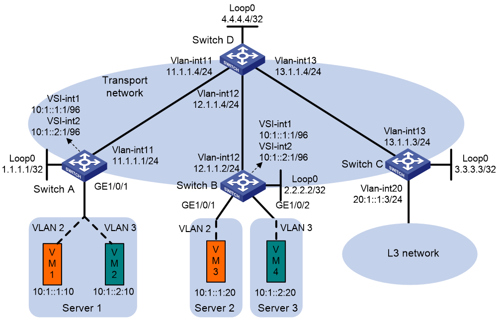
As shown in Figure 9, VM 1 is the multicast source of multicast group 225.0.0.0, and the other VMs are multicast receivers. Configure MVXLAN to forward the multicast traffic from the source to the receivers.
· Configure VXLAN 10 and VXLAN 20 on Switch A and Switch B to extend VLAN 2 and VLAN 3 across the sites.
· Configure Switch A and Switch B as distributed EVPN gateways to provide gateway services. Configure Switch C as a border gateway to provide access to the connected Layer 3 network.
· Configure Switch D as an RR to reflect BGP EVPN routes between Switch A, Switch B, and Switch C.
· Configure PIM-SM on the transport-facing interfaces of Switches A through D. Configure IGMP snooping on Switches A through C for multicast forwarding entry creation.

Procedure
1. On VM 1 and VM 3, specify 10.1.1.1 as the gateway address. On VM 2 and VM 4, specify 10.1.2.1 as the gateway address. (Details not shown.)
2. Configure IP addresses and unicast routing settings:
# Assign IP addresses to interfaces, as shown in Figure 9. (Details not shown.)
# Configure OSPF on all transport network switches (Switches A through D) for them to reach one another. (Details not shown.)
3. Configure Switch A:
# Enable L2VPN and IP multicast routing.
<SwitchA> system-view
[SwitchA] l2vpn enable
[SwitchA] multicast routing
[SwitchA-mrib] quit
# Enable the IGMP snooping feature.
[SwitchA] igmp-snooping
[SwitchA-igmp-snooping] quit
# Disable remote MAC address learning and remote ARP learning.
[SwitchA] vxlan tunnel mac-learning disable
[SwitchA] vxlan tunnel arp-learning disable
# Create VLAN-interface 11 and enter its view.
[SwitchA] vlan 11
[SwitchA-vlan11] quit
[SwitchA] interface vlan-interface 11
# Enable PIM-SM on VLAN-interface 11.
[SwitchA-Vlan-interface11] pim sm
[SwitchA-Vlan-interface11] quit
# Create an EVPN instance on VSI vpna.
[SwitchA] vsi vpna
[SwitchA-vsi-vpna] evpn encapsulation vxlan
[SwitchA-vsi-vpna-evpn-vxlan] route-distinguisher auto
[SwitchA-vsi-vpna-evpn-vxlan] vpn-target auto
[SwitchA-vsi-vpna-evpn-vxlan] quit
# Enable IGMP snooping and IGMP snooping proxying on VSI vpna.
[SwitchA-vsi-vpna] igmp-snooping enable
[SwitchA-vsi-vpna] igmp-snooping proxy enable
# Create VXLAN 10.
[SwitchA-vsi-vpna] vxlan 10
[SwitchA-vsi-vpna-vxlan-10] quit
[SwitchA-vsi-vpna] quit
# Create an EVPN instance on VSI vpnb.
[SwitchA] vsi vpnb
[SwitchA-vsi-vpnb] evpn encapsulation vxlan
[SwitchA-vsi-vpnb-evpn-vxlan] route-distinguisher auto
[SwitchA-vsi-vpnb-evpn-vxlan] vpn-target auto
[SwitchA-vsi-vpnb-evpn-vxlan] quit
# Enable IGMP snooping and IGMP snooping proxying on VSI vpnb.
[SwitchA-vsi-vpnb] igmp-snooping enable
[SwitchA-vsi-vpnb] igmp-snooping proxy enable
# Create VXLAN 20.
[SwitchA-vsi-vpnb] vxlan 20
[SwitchA-vsi-vpnb-vxlan-20] quit
[SwitchA-vsi-vpnb] quit
# Configure BGP to advertise BGP EVPN routes.
[SwitchA] bgp 200
[SwitchA-bgp-default] peer 4.4.4.4 as-number 200
[SwitchA-bgp-default] peer 4.4.4.4 connect-interface loopback 0
[SwitchA-bgp-default] address-family l2vpn evpn
[SwitchA-bgp-default-evpn] peer 4.4.4.4 enable
[SwitchA-bgp-default-evpn] quit
[SwitchA-bgp-default] quit
# Create VLAN 2.
[SwitchA] vlan 2
[SwitchA-vlan2] quit
# Create VLAN 3.
[SwitchA] vlan 3
[SwitchA-vlan3] quit
# Configure GigabitEthernet 1/0/1 as a trunk port and assign it to VLAN 2 and VLAN 3.
[SwitchA] interface gigabitethernet 1/0/1
[SwitchA-GigabitEthernet1/0/1] port link-type trunk
[SwitchA-GigabitEthernet1/0/1] port trunk permit vlan 2 3
# On GigabitEthernet 1/0/1, create Ethernet service instance 1000 to match VLAN 2.
[SwitchA-GigabitEthernet1/0/1] service-instance 1000
[SwitchA-GigabitEthernet1/0/1-srv1000] encapsulation s-vid 2
# Map Ethernet service instance 1000 to VSI vpna.
[SwitchA-GigabitEthernet1/0/1-srv1000] xconnect vsi vpna
[SwitchA-GigabitEthernet1/0/1-srv1000] quit
# On GigabitEthernet 1/0/1, create Ethernet service instance 2000 to match VLAN 3.
[SwitchA-GigabitEthernet1/0/1] service-instance 2000
[SwitchA-GigabitEthernet1/0/1-srv2000] encapsulation s-vid 3
# Map Ethernet service instance 2000 to VSI vpnb.
[SwitchA-GigabitEthernet1/0/1-srv2000] xconnect vsi vpnb
[SwitchA-GigabitEthernet1/0/1-srv2000] quit
[SwitchA-GigabitEthernet1/0/1] quit
# Configure RD and route target settings for VPN instance vpna.
[SwitchA] ip vpn-instance vpna
[SwitchA-vpn-instance-vpna] route-distinguisher 1:1
[SwitchA-vpn-instance-vpna] address-family ipv4
[SwitchA-vpn-ipv4-vpna] vpn-target 1:1
[SwitchA-vpn-ipv4-vpna] quit
[SwitchA-vpn-instance-vpna] address-family evpn
[SwitchA-vpn-evpn-vpna] vpn-target 1:1
[SwitchA-vpn-evpn-vpna] quit
[SwitchA-vpn-instance-vpna] quit
# Configure VSI-interface 1.
[SwitchA] interface vsi-interface 1
[SwitchA-Vsi-interface1] ip binding vpn-instance vpna
[SwitchA-Vsi-interface1] ip address 10.1.1.1 255.255.255.0
[SwitchA-Vsi-interface1] pim sm
[SwitchA-Vsi-interface1] pim distributed-dr
[SwitchA-Vsi-interface1] mac-address 1-1-1
[SwitchA-Vsi-interface1] distributed-gateway local
[SwitchA-Vsi-interface1] local-proxy-arp enable
[SwitchA-Vsi-interface1] quit
# Configure VSI-interface 2.
[SwitchA] interface vsi-interface 2
[SwitchA-Vsi-interface2] ip binding vpn-instance vpna
[SwitchA-Vsi-interface2] ip address 10.1.2.1 255.255.255.0
[SwitchA-Vsi-interface2] igmp enable
[SwitchA-Vsi-interface2] mac-address 2-2-2
[SwitchA-Vsi-interface2] distributed-gateway local
[SwitchA-Vsi-interface2] local-proxy-arp enable
[SwitchA-Vsi-interface2] quit
# Associate VSI-interface 3 with VPN instance vpna, and configure the L3 VXLAN ID as 1000 for the VPN instance.
[SwitchA] interface vsi-interface 3
[SwitchA-Vsi-interface3] ip binding vpn-instance vpna
[SwitchA-Vsi-interface3] l3-vni 1000
[SwitchA-Vsi-interface3] pim sm
[SwitchA-Vsi-interface3] quit
# Enable IP multicast routing for VPN instance vpna.
[SwitchA] multicast routing vpn-instance vpna
[SwitchA-mrib-vpna] quit
# Create an MDT-based MVXLAN for VPN instance vpna and enter MVXLAN IPv4 address family view. Configure the default group, MVXLAN source interface, and data group range settings.
[SwitchA] multicast-vpn vxlan vpn-instance vpna mode mdt
[SwitchA-mvxlan-vpna] address-family ipv4
[SwitchA-mvxlan-vpna-ipv4] default-group 236.0.0.1
[SwitchA-mvxlan-vpna-ipv4] source loopback 0
[SwitchA-mvxlan-vpna-ipv4] data-group 239.0.1.0 30
[SwitchA-mvxlan-vpna-ipv4] quit
[SwitchA-mvxlan-vpna] quit
# Configure Loopback 1.
[SwitchA] interface loopback 1
[SwitchA-LoopBack1] ip binding vpn-instance vpna
[SwitchA-LoopBack1] ip address 12.12.12.12 32
[SwitchA-LoopBack1] pim sm
[SwitchA-LoopBack1] quit
# Enter VPN instance PIM view, and configure Loopback 1 as a candidate-BSR and candidate-RP in VPN instance vpna.
[SwitchA] pim vpn-instance vpna
[SwitchA-pim-vpna] c-bsr 12.12.12.12
[SwitchA-pim-vpna] c-rp 12.12.12.12
[SwitchA-pim-vpna] quit
# Specify VSI-interface 1 as the gateway interface for VSI vpna.
[SwitchA] vsi vpna
[SwitchA-vsi-vpna] gateway vsi-interface 1
[SwitchA-vsi-vpna] quit
# Specify VSI-interface 2 as the gateway interface for VSI vpnb.
[SwitchA] vsi vpnb
[SwitchA-vsi-vpnb] gateway vsi-interface 2
[SwitchA-vsi-vpnb] quit
4. Configure Switch B:
# Enable L2VPN and IP multicast routing.
<SwitchB> system-view
[SwitchB] l2vpn enable
[SwitchB] multicast routing
[SwitchB-mrib] quit
# Enable the IGMP snooping feature.
[SwitchB] igmp-snooping
[SwitchB-igmp-snooping] quit
# Disable remote MAC address learning and remote ARP learning.
[SwitchB] vxlan tunnel mac-learning disable
[SwitchB] vxlan tunnel arp-learning disable
# Create VLAN-interface 12 and enter its view.
[SwitchB] vlan 12
[SwitchB-vlan12] quit
[SwitchB] interface vlan-interface 12
# Enable PIM-SM on VLAN-interface 12.
[SwitchB-Vlan-interface12] pim sm
[SwitchB-Vlan-interface12] quit
# Create an EVPN instance on VSI vpna.
[SwitchB] vsi vpna
[SwitchB-vsi-vpna] evpn encapsulation vxlan
[SwitchB-vsi-vpna-evpn-vxlan] route-distinguisher auto
[SwitchB-vsi-vpna-evpn-vxlan] vpn-target auto
[SwitchB-vsi-vpna-evpn-vxlan] quit
# Enable IGMP snooping and IGMP snooping proxying on VSI vpna.
[SwitchB-vsi-vpna] igmp-snooping enable
[SwitchB-vsi-vpna] igmp-snooping proxy enable
# Create VXLAN 10.
[SwitchB-vsi-vpna] vxlan 10
[SwitchB-vsi-vpna-vxlan-10] quit
[SwitchB-vsi-vpna] quit
# Create an EVPN instance on VSI vpnb.
[SwitchB] vsi vpnb
[SwitchB-vsi-vpnb] evpn encapsulation vxlan
[SwitchB-vsi-vpnb-evpn-vxlan] route-distinguisher auto
[SwitchB-vsi-vpnb-evpn-vxlan] vpn-target auto
[SwitchB-vsi-vpnb-evpn-vxlan] quit
# Enable IGMP snooping and IGMP snooping proxying on VSI vpnb.
[SwitchB-vsi-vpnb] igmp-snooping enable
[SwitchB-vsi-vpnb] igmp-snooping proxy enable
# Create VXLAN 20.
[SwitchB-vsi-vpnb] vxlan 20
[SwitchB-vsi-vpnb-vxlan-20] quit
[SwitchB-vsi-vpnb] quit
# Configure BGP to advertise BGP EVPN routes.
[SwitchB] bgp 200
[SwitchB-bgp-default] peer 4.4.4.4 as-number 200
[SwitchB-bgp-default] peer 4.4.4.4 connect-interface loopback 0
[SwitchB-bgp-default] address-family l2vpn evpn
[SwitchB-bgp-default-evpn] peer 4.4.4.4 enable
[SwitchB-bgp-default-evpn] quit
[SwitchB-bgp-default] quit
# Create VLAN 2.
[SwitchB] vlan 2
[SwitchB-vlan2] quit
# Create VLAN 3.
[SwitchB] vlan 3
[SwitchB-vlan3] quit
# Configure GigabitEthernet 1/0/1 as a trunk port and assign it to VLAN 2.
[SwitchB] interface gigabitethernet 1/0/1
[SwitchB-GigabitEthernet1/0/1] port link-type trunk
[SwitchB-GigabitEthernet1/0/1] port trunk permit vlan 2
# On GigabitEthernet 1/0/1, create Ethernet service instance 1000 to match VLAN 2.
[SwitchB-GigabitEthernet1/0/1] service-instance 1000
[SwitchB-GigabitEthernet1/0/1-srv1000] encapsulation s-vid 2
# Map Ethernet service instance 1000 to VSI vpna.
[SwitchB-GigabitEthernet1/0/1-srv1000] xconnect vsi vpna
[SwitchB-GigabitEthernet1/0/1-srv1000] quit
# Configure GigabitEthernet 1/0/1 as a trunk port and assign it to VLAN 3.
[SwitchB] interface gigabitethernet 1/0/1
[SwitchB-GigabitEthernet1/0/1] port link-type trunk
[SwitchB-GigabitEthernet1/0/1] port trunk permit vlan 3
# On GigabitEthernet 1/0/1, create Ethernet service instance 2000 to match VLAN 3.
[SwitchB-GigabitEthernet1/0/1] service-instance 2000
[SwitchB-GigabitEthernet1/0/1-srv2000] encapsulation s-vid 3
# Map Ethernet service instance 2000 to VSI vpnb.
[SwitchB-GigabitEthernet1/0/1-srv2000] xconnect vsi vpnb
[SwitchB-GigabitEthernet1/0/1-srv2000] quit
[SwitchB-GigabitEthernet1/0/1] quit
# Configure RD and route target settings for VPN instance vpna.
[SwitchB] ip vpn-instance vpna
[SwitchB-vpn-instance-vpna] route-distinguisher 1:1
[SwitchB-vpn-instance-vpna] address-family ipv4
[SwitchB-vpn-ipv4-vpna] vpn-target 1:1
[SwitchB-vpn-ipv4-vpna] quit
[SwitchB-vpn-instance-vpna] address-family evpn
[SwitchB-vpn-evpn-vpna] vpn-target 1:1
[SwitchB-vpn-evpn-vpna] quit
[SwitchB-vpn-instance-vpna] quit
# Configure VSI-interface 1.
[SwitchB] interface vsi-interface 1
[SwitchB-Vsi-interface1] ip binding vpn-instance vpna
[SwitchB-Vsi-interface1] ip address 10.1.1.1 255.255.255.0
[SwitchB-Vsi-interface1] igmp enable
[SwitchB-Vsi-interface1] mac-address 1-1-1
[SwitchB-Vsi-interface1] distributed-gateway local
[SwitchB-Vsi-interface1] local-proxy-arp enable
[SwitchB-Vsi-interface1] quit
# Configure VSI-interface 2.
[SwitchB] interface vsi-interface 2
[SwitchB-Vsi-interface2] ip binding vpn-instance vpna
[SwitchB-Vsi-interface2] ip address 10.1.2.1 255.255.255.0
[SwitchB-Vsi-interface2] igmp enable
[SwitchB-Vsi-interface2] mac-address 2-2-2
[SwitchB-Vsi-interface2] distributed-gateway local
[SwitchB-Vsi-interface2] local-proxy-arp enable
[SwitchB-Vsi-interface2] quit
# Associate VSI-interface 3 with VPN instance vpna, and configure the L3 VXLAN ID as 1000 for the VPN instance.
[SwitchB] interface vsi-interface 3
[SwitchB-Vsi-interface3] ip binding vpn-instance vpna
[SwitchB-Vsi-interface3] l3-vni 1000
[SwitchB-Vsi-interface3] pim sm
[SwitchB-Vsi-interface3] quit
# Enable IP multicast routing for VPN instance vpna.
[SwitchB] multicast routing vpn-instance vpna
[SwitchB-mrib-vpna] quit
# Create an MDT-based MVXLAN for VPN instance vpna and enter MVXLAN IPv4 address family view. Configure the MVXLAN source interface.
[SwitchB] multicast-vpn vxlan vpn-instance vpna mode mdt
[SwitchB-mvxlan-vpna] address-family ipv4
[SwitchB-mvxlan-vpna-ipv4] source loopback 0
[SwitchB-mvxlan-vpna-ipv4] quit
[SwitchB-mvxlan-vpna] quit
# Configure Loopback 1.
[SwitchB] interface loopback 1
[SwitchB-LoopBack1] ip binding vpn-instance vpna
[SwitchB-LoopBack1] ip address 12.12.12.12 32
[SwitchB-LoopBack1] pim sm
[SwitchB-LoopBack1] quit
# Enter VPN instance PIM view, and configure Loopback 1 as a candidate-BSR and candidate-RP in VPN instance vpna.
[SwitchB] pim vpn-instance vpna
[SwitchB-pim-vpna] c-bsr 12.12.12.12
[SwitchB-pim-vpna] c-rp 12.12.12.12
[SwitchB-pim-vpna] quit
# Specify VSI-interface 1 as the gateway interface for VSI vpna.
[SwitchB] vsi vpna
[SwitchB-vsi-vpna] gateway vsi-interface 1
[SwitchB-vsi-vpna] quit
# Specify VSI-interface 2 as the gateway interface for VSI vpnb.
[SwitchB] vsi vpnb
[SwitchB-vsi-vpnb] gateway vsi-interface 2
[SwitchB-vsi-vpnb] quit
5. Configure Switch C:
# Enable L2VPN and IP multicast routing.
<SwitchC> system-view
[SwitchC] l2vpn enable
[SwitchC] multicast routing
[SwitchC-mrib] quit
# Disable remote MAC address learning and remote ARP learning.
[SwitchC] vxlan tunnel mac-learning disable
[SwitchC] vxlan tunnel arp-learning disable
# Create VLAN-interface 13 and enter its view.
[SwitchC] vlan 13
[SwitchC-vlan13] quit
[SwitchC] interface vlan-interface 13
# Enable PIM-SM on VLAN-interface 13.
[SwitchC-Vlan-interface13] pim sm
[SwitchC-Vlan-interface13] quit
# Configure BGP to advertise BGP EVPN routes.
[SwitchC] bgp 200
[SwitchC-bgp-default] peer 4.4.4.4 as-number 200
[SwitchC-bgp-default] peer 4.4.4.4 connect-interface loopback 0
[SwitchC-bgp-default] address-family l2vpn evpn
[SwitchC-bgp-default-evpn] peer 4.4.4.4 enable
[SwitchC-bgp-default-evpn] quit
[SwitchC-bgp-default] quit
# Configure RD and route target settings for VPN instance vpna.
[SwitchC] ip vpn-instance vpna
[SwitchC-vpn-instance-vpna] route-distinguisher 1:1
[SwitchC-vpn-instance-vpna] address-family ipv4
[SwitchC-vpn-ipv4-vpna] vpn-target 1:1
[SwitchC-vpn-ipv4-vpna] quit
[SwitchC-vpn-instance-vpna] address-family evpn
[SwitchC-vpn-evpn-vpna] vpn-target 1:1
[SwitchC-vpn-evpn-vpna] quit
[SwitchC-vpn-instance-vpna] quit
# Associate VSI-interface 3 with VPN instance vpna, and configure the L3 VXLAN ID as 1000 for the VPN instance.
[SwitchC] interface vsi-interface 3
[SwitchC-Vsi-interface3] ip binding vpn-instance vpna
[SwitchC-Vsi-interface3] l3-vni 1000
[SwitchC-Vsi-interface3] pim sm
[SwitchC-Vsi-interface3] quit
# Enable IP multicast routing on VPN instance vpna.
[SwitchC] multicast routing vpn-instance vpna
[SwitchC-mrib-vpna] quit
# Create an MDT-based MVXLAN for VPN instance vpna and enter MVXLAN IPv4 address family view. Configure the MVXLAN source interface.
[SwitchC] multicast-vpn vxlan vpn-instance vpna mode mdt
[SwitchC-mvxlan-vpna] address-family ipv4
[SwitchC-mvxlan-vpna-ipv4] source loopback 0
[SwitchC-mvxlan-vpna-ipv4] quit
[SwitchC-mvxlan-vpna] quit
# Configure Loopback 1.
[SwitchC] interface loopback 1
[SwitchC-LoopBack1] ip binding vpn-instance vpna
[SwitchC-LoopBack1] ip address 12.12.12.12 32
[SwitchC-LoopBack1] pim sm
[SwitchC-LoopBack1] quit
# Enter VPN instance PIM view, and configure Loopback 1 as a candidate-BSR and candidate-RP in VPN instance vpna.
[SwitchC] pim vpn-instance vpna
[SwitchC-pim-vpna] c-bsr 12.12.12.12
[SwitchC-pim-vpna] c-rp 12.12.12.12
[SwitchC-pim-vpna] quit
# Configure a default route. Specify the next hop as 20.1.1.100, the IP address of a device in the Layer 3 network.
[SwitchC] ip route-static vpn-instance vpna 0.0.0.0 0 20.1.1.100
# Import the default route to the BGP IPv4 unicast routing table of VPN instance vpna.
[SwitchC] bgp 200
[SwitchC-bgp-default] ip vpn-instance vpna
[SwitchC-bgp-default-vpna] address-family ipv4 unicast
[SwitchC-bgp-default-ipv4-vpna] default-route imported
[SwitchC-bgp-default-ipv4-vpna] import-route static
[SwitchC-bgp-default-ipv4-vpna] quit
[SwitchC-bgp-default-vpna] quit
[SwitchC-bgp-default] quit
# Create VLAN 20 and enter its view.
[SwitchC] vlan 20
[SwitchC-vlan20] quit
# Associate WAN-facing interface VLAN-interface 20 with VPN instance vpna.
[SwitchC] interface vlan-interface 20
[SwitchC-Vlan-interface20] ip binding vpn-instance vpna
[SwitchC-Vlan-interface20] ip address 20.1.1.3 24
[SwitchC-Vlan-interface20] pim sm
[SwitchC-Vlan-interface20] quit
6. Configure Switch D:
# Enable IP multicast routing.
<SwitchD> system-view
[SwitchD] multicast routing
[SwitchD-mrib] quit
# Enter PIM view, and configure Loopback 0 as a candidate-BSR and candidate-RP in the public network.
[SwitchD] pim
[SwitchD-pim] c-bsr 4.4.4.4
[SwitchD-pim] c-rp 4.4.4.4
[SwitchD-pim] quit
# Enable PIM-SM on VLAN-interface 11.
[SwitchD] interface vlan-interface11
[SwitchD-Vlan-interface11] pim sm
[SwitchD-Vlan-interface11] quit
# Enable PIM-SM on VLAN-interface 12.
[SwitchD] interface vlan-interface12
[SwitchD-Vlan-interface12] pim sm
[SwitchD-Vlan-interface12] quit
# Enable PIM-SM on VLAN-interface 13.
[SwitchD] interface vlan-interface13
[SwitchD-Vlan-interface13] pim sm
[SwitchD-Vlan-interface13] quit
# Establish BGP connections with other transport network switches.
[SwitchD] bgp 200
[SwitchD-bgp-default] group evpn
[SwitchD-bgp-default] peer 1.1.1.1 group evpn
[SwitchD-bgp-default] peer 2.2.2.2 group evpn
[SwitchD-bgp-default] peer 3.3.3.3 group evpn
[SwitchD-bgp-default] peer evpn as-number 200
[SwitchD-bgp-default] peer evpn connect-interface loopback 0
# Configure BGP to advertise BGP EVPN routes, and disable route target filtering of received BGP EVPN routes.
[SwitchD-bgp-default] address-family l2vpn evpn
[SwitchD-bgp-default-evpn] peer evpn enable
[SwitchD-bgp-default-evpn] undo policy vpn-target
# Configure Switch D as an RR.
[SwitchD-bgp-default-evpn] peer evpn reflect-client
[SwitchD-bgp-default-evpn] quit
[SwitchD-bgp-default] quit
Verifying the configuration
1. Verify the multicast routing information on Switch A:
# Verify that Switch A has multicast routing entries for VPN instance vpna.
<SwitchA> display pim vpn-instance vpna routing-table
Total 1 (*, G) entries; 1 (S, G) entries
(*, 225.0.0.0)
RP: 12.12.12.12 (local)
Protocol: pim-sm, Flag: WC RC
UpTime: 02:57:31
Upstream interface: Register-Tunnel0
Upstream neighbor: NULL
RPF prime neighbor: NULL
Downstream interface information:
Total number of downstream interfaces: 1
1: MTunnel0
Protocol: MD, UpTime: 02:57:31, Expires: -
(10.1.1.10, 225.0.0.0)
RP: 12.12.12.12 (local)
Protocol: pim-sm, Flag: SPT 2MSDP LOC ACT SQ RC 2MVPN
UpTime: 04:44:08
Upstream interface: Vsi-interface1
Upstream neighbor: NULL
RPF prime neighbor: NULL
Downstream interface information:
Total number of downstream interfaces: 1
1: MTunnel1
Protocol: MD, UpTime: 02:00:27, Expires: -
# Verify that Switch A has multicast routing entries for the public network.
<SwitchA> display pim routing-table
Total 0 (*, G) entries; 2 (S, G) entries
(1.1.1.1, 236.0.0.1)
RP: 4.4.4.4
Protocol: pim-sm, Flag: SPT LOC VXLAN_L3
UpTime: 02:09:52
Upstream interface: MTunnel0 (VPN: vpna)
Upstream neighbor: NULL
RPF prime neighbor: NULL
Downstream interface information:
Total number of downstream interfaces: 1
1: Vlan-interface11
Protocol: pim-sm, UpTime: 01:16:34, Expires: 00:03:10
(1.1.1.1, 239.0.1.0)
RP: 4.4.4.4
Protocol: pim-sm, Flag: SPT LOC VXLAN_L3
UpTime: 02:08:52
Upstream interface: MTunnel1 (VPN: vpna)
Upstream neighbor: NULL
RPF prime neighbor: NULL
Downstream interface information:
Total number of downstream interfaces: 1
1: Vlan-interface11
Protocol: pim-sm, UpTime: 01:15:34, Expires: 00:03:11
2. Verify the multicast routing information on Switch B:
# Verify that Switch B has multicast routing entries for VPN instance vpna.
<SwitchB> display pim vpn-instance vpna routing-table
Total 1 (*, G) entries; 1 (S, G) entries
(*, 225.0.0.0)
RP: 12.12.12.12 (local)
Protocol: pim-sm, Flag: WC
UpTime: 05:04:06
Upstream interface: Register-Tunnel0
Upstream neighbor: NULL
RPF prime neighbor: NULL
Downstream interface information:
Total number of downstream interfaces: 1
1: Vsi-interface1
Protocol: igmp, UpTime: 05:04:06, Expires: -
(10.1.1.10, 225.0.0.0)
RP: 12.12.12.12 (local)
Protocol: pim-sm, Flag: SPT ACT RQ FROMVXLAN
UpTime: 01:57:12
Upstream interface: MVXLAN-UPE0 (0.0.0.0)
Upstream neighbor: NULL
RPF prime neighbor: NULL
Downstream interface information:
Total number of downstream interfaces: 1
1: Vsi-interface1
Protocol: pim-sm, UpTime: 01:57:12, Expires: -
# Verify that Switch B has multicast routing entries for the public network.
<SwitchB> display pim routing-table
Total 0 (*, G) entries; 2 (S, G) entries
(1.1.1.1, 236.0.0.1)
RP: 4.4.4.4
Protocol: pim-sm, Flag: SPT
UpTime: 01:59:46
Upstream interface: Vlan-interface12
Upstream neighbor: 12.1.1.4
RPF prime neighbor: 12.1.1.4
Downstream interface information:
Total number of downstream interfaces: 1
1: MVXLAN-UPE0
Protocol: MD, UpTime: 01:59:46, Expires: -
(1.1.1.1, 239.0.1.0)
RP: 4.4.4.4
Protocol: pim-sm, Flag: SPT ACT
UpTime: 01:58:46
Upstream interface: Vlan-interface12
Upstream neighbor: 12.1.1.4
RPF prime neighbor: 12.1.1.4
Downstream interface information:
Total number of downstream interfaces: 1
1: MVXLAN-UPE0
Protocol: MD, UpTime: 01:58:46, Expires: -
Example: Configuring intra-VPN MVXLAN Layer 3 multicast forwarding (IPv6 site network)
Network configuration
As shown in Figure 9, VM 1 is the multicast source of multicast group FF1E::, and the other VMs are multicast receivers. Configure MVXLAN to forward the multicast traffic from the source to the receivers.
· Configure VXLAN 10 and VXLAN 20 on Switch A and Switch B to extend VLAN 2 and VLAN 3 across the sites.
· Configure Switch A and Switch B as distributed EVPN gateways to provide gateway services. Configure Switch C as a border gateway to provide access to the connected Layer 3 network.
· Configure Switch D as an RR to reflect BGP EVPN routes between Switch A, Switch B, and Switch C.
· Configure PIM-SM on the transport-facing interfaces of Switches A through D. Configure MLD snooping on Switches A through C for multicast forwarding entry creation.
Figure 10 Network diagram
Procedure
1. On VM 1 and VM 3, specify 10:1::1:1 as the gateway address. On VM 2 and VM 4, specify 10:1::2:1 as the gateway address. (Details not shown.)
2. Configure IP addresses and unicast routing settings:
# Assign IP addresses to interfaces, as shown in Figure 9. (Details not shown.)
# Configure OSPF on all transport network switches (Switches A through D) for them to reach one another. (Details not shown.)
3. Configure Switch A:
# Enable L2VPN and IP multicast routing.
<SwitchA> system-view
[SwitchA] l2vpn enable
[SwitchA] multicast routing
[SwitchA-mrib] quit
# Enable the MLD snooping feature.
[SwitchA] mld-snooping
[SwitchA-mld-snooping] quit
# Disable remote MAC address learning and remote ND learning.
[SwitchA] vxlan tunnel mac-learning disable
[SwitchA] vxlan tunnel nd-learning disable
# Create VLAN-interface 11 and enter its view.
[SwitchA] vlan 11
[SwitchA-vlan11] quit
[SwitchA] interface vlan-interface 11
# Enable PIM-SM on VLAN-interface 11.
[SwitchA-Vlan-interface11] pim sm
[SwitchA-Vlan-interface11] quit
# Create an EVPN instance on VSI vpna.
[SwitchA] vsi vpna
[SwitchA-vsi-vpna] evpn encapsulation vxlan
[SwitchA-vsi-vpna-evpn-vxlan] route-distinguisher auto
[SwitchA-vsi-vpna-evpn-vxlan] vpn-target auto
[SwitchA-vsi-vpna-evpn-vxlan] quit
# Enable MLD snooping and MLD snooping proxying on VSI vpna.
[SwitchA-vsi-vpna] mld-snooping enable
[SwitchA-vsi-vpna] mld-snooping proxy enable
# Create VXLAN 10.
[SwitchA-vsi-vpna] vxlan 10
[SwitchA-vsi-vpna-vxlan-10] quit
[SwitchA-vsi-vpna] quit
# Create an EVPN instance on VSI vpnb.
[SwitchA] vsi vpnb
[SwitchA-vsi-vpnb] evpn encapsulation vxlan
[SwitchA-vsi-vpnb-evpn-vxlan] route-distinguisher auto
[SwitchA-vsi-vpnb-evpn-vxlan] vpn-target auto
[SwitchA-vsi-vpnb-evpn-vxlan] quit
# Enable MLD snooping and MLD snooping proxying on VSI vpnb.
[SwitchA-vsi-vpnb] mld-snooping enable
[SwitchA-vsi-vpnb] mld-snooping proxy enable
# Create VXLAN 20.
[SwitchA-vsi-vpnb] vxlan 20
[SwitchA-vsi-vpnb-vxlan-20] quit
[SwitchA-vsi-vpnb] quit
# Configure BGP to advertise BGP EVPN routes.
[SwitchA] bgp 200
[SwitchA-bgp-default] peer 4.4.4.4 as-number 200
[SwitchA-bgp-default] peer 4.4.4.4 connect-interface loopback 0
[SwitchA-bgp-default] address-family l2vpn evpn
[SwitchA-bgp-default-evpn] peer 4.4.4.4 enable
[SwitchA-bgp-default-evpn] quit
[SwitchA-bgp-default] quit
# Create VLAN 2.
[SwitchA] vlan 2
[SwitchA-vlan2] quit
# Create VLAN 3.
[SwitchA] vlan 3
[SwitchA-vlan3] quit
# Configure GigabitEthernet 1/0/1 as a trunk port and assign it to VLAN 2 and VLAN 3.
[SwitchA] interface gigabitethernet 1/0/1
[SwitchA-GigabitEthernet1/0/1] port link-type trunk
[SwitchA-GigabitEthernet1/0/1] port trunk permit vlan 2 3
# On GigabitEthernet 1/0/1, create Ethernet service instance 1000 to match VLAN 2.
[SwitchA-GigabitEthernet1/0/1] service-instance 1000
[SwitchA-GigabitEthernet1/0/1-srv1000] encapsulation s-vid 2
# Map Ethernet service instance 1000 to VSI vpna.
[SwitchA-GigabitEthernet1/0/1-srv1000] xconnect vsi vpna
[SwitchA-GigabitEthernet1/0/1-srv1000] quit
# On GigabitEthernet 1/0/1, create Ethernet service instance 2000 to match VLAN 3.
[SwitchA-GigabitEthernet1/0/1] service-instance 2000
[SwitchA-GigabitEthernet1/0/1-srv2000] encapsulation s-vid 3
# Map Ethernet service instance 2000 to VSI vpnb.
[SwitchA-GigabitEthernet1/0/1-srv2000] xconnect vsi vpnb
[SwitchA-GigabitEthernet1/0/1-srv2000] quit
[SwitchA-GigabitEthernet1/0/1] quit
# Configure RD and route target settings for VPN instance vpna.
[SwitchA] ip vpn-instance vpna
[SwitchA-vpn-instance-vpna] route-distinguisher 1:1
[SwitchA-vpn-instance-vpna] address-family ipv6
[SwitchA-vpn-ipv6-vpna] vpn-target 1:1
[SwitchA-vpn-ipv6-vpna] quit
[SwitchA-vpn-instance-vpna] address-family evpn
[SwitchA-vpn-evpn-vpna] vpn-target 1:1
[SwitchA-vpn-evpn-vpna] quit
[SwitchA-vpn-instance-vpna] quit
# Configure VSI-interface 1.
[SwitchA] interface vsi-interface 1
[SwitchA-Vsi-interface1] ip binding vpn-instance vpna
[SwitchA-Vsi-interface1] ipv6 address 10:1::1:1 96
[SwitchA-Vsi-interface1] ipv6 pim sm
[SwitchA-Vsi-interface1] ipv6 pim distributed-dr
[SwitchA-Vsi-interface1] mac-address 1-1-1
[SwitchA-Vsi-interface1] distributed-gateway local
[SwitchA-Vsi-interface1] local-proxy-arp enable
[SwitchA-Vsi-interface1] quit
# Configure VSI-interface 2.
[SwitchA] interface vsi-interface 2
[SwitchA-Vsi-interface2] ip binding vpn-instance vpna
[SwitchA-Vsi-interface2] ipv6 address 10:1::2:1 96
[SwitchA-Vsi-interface2] mld enable
[SwitchA-Vsi-interface2] mac-address 2-2-2
[SwitchA-Vsi-interface2] distributed-gateway local
[SwitchA-Vsi-interface2] local-proxy-arp enable
[SwitchA-Vsi-interface2] quit
# Associate VSI-interface 3 with VPN instance vpna, and configure the L3 VXLAN ID as 1000 for the VPN instance.
[SwitchA] interface vsi-interface 3
[SwitchA-Vsi-interface3] ip binding vpn-instance vpna
[SwitchA-Vsi-interface3] l3-vni 1000
[SwitchA-Vsi-interface3] ipv6 pim sm
[SwitchA-Vsi-interface3] quit
# Enable IP multicast routing for VPN instance vpna.
[SwitchA] ipv6 multicast routing vpn-instance vpna
[SwitchA-mrib6-vpna] quit
# Create an MDT-based MVXLAN for VPN instance vpna and enter MVXLAN IPv6 address family view. Configure the default group, MVXLAN source interface, and data group range settings.
[SwitchA] multicast-vpn vxlan vpn-instance vpna mode mdt
[SwitchA-mvxlan-vpna] address-family ipv6
[SwitchA-mvxlan-vpna-ipv6] default-group 236.0.0.1
[SwitchA-mvxlan-vpna-ipv6] source loopback 0
[SwitchA-mvxlan-vpna-ipv6] data-group 239.0.1.0 30
[SwitchA-mvxlan-vpna-ipv6] quit
[SwitchA-mvxlan-vpna] quit
# Configure Loopback 1.
[SwitchA] interface loopback 1
[SwitchA-LoopBack1] ip binding vpn-instance vpna
[SwitchA-LoopBack1] ipv6 address 12:12::12:12 128
[SwitchA-LoopBack1] ipv6 pim sm
[SwitchA-LoopBack1] quit
# Enter VPN instance IPv6 PIM view, and configure Loopback 1 as a candidate-BSR and candidate-RP in VPN instance vpna.
[SwitchA] ipv6 pim vpn-instance vpna
[SwitchA-pim6-vpna] c-bsr 12:12::12:12
[SwitchA-pim6-vpna] c-rp 12:12::12:12
[SwitchA-pim6-vpna] quit
# Specify VSI-interface 1 as the gateway interface for VSI vpna.
[SwitchA] vsi vpna
[SwitchA-vsi-vpna] gateway vsi-interface 1
[SwitchA-vsi-vpna] quit
# Specify VSI-interface 2 as the gateway interface for VSI vpnb.
[SwitchA] vsi vpnb
[SwitchA-vsi-vpnb] gateway vsi-interface 2
[SwitchA-vsi-vpnb] quit
4. Configure Switch B:
# Enable L2VPN and IP multicast routing.
<SwitchB> system-view
[SwitchB] l2vpn enable
[SwitchB] multicast routing
[SwitchB-mrib] quit
# Enable the MLD snooping feature.
[SwitchB] mld-snooping
[SwitchB-mld-snooping] quit
# Disable remote MAC address learning and remote ND learning.
[SwitchB] vxlan tunnel mac-learning disable
[SwitchB] vxlan tunnel nd-learning disable
# Create VLAN-interface 12 and enter its view.
[SwitchB] vlan 12
[SwitchB-vlan12] quit
[SwitchB] interface vlan-interface 12
# Enable PIM-SM on VLAN-interface 12.
[SwitchB-Vlan-interface12] pim sm
[SwitchB-Vlan-interface12] quit
# Create an EVPN instance on VSI vpna.
[SwitchB] vsi vpna
[SwitchB-vsi-vpna] evpn encapsulation vxlan
[SwitchB-vsi-vpna-evpn-vxlan] route-distinguisher auto
[SwitchB-vsi-vpna-evpn-vxlan] vpn-target auto
[SwitchB-vsi-vpna-evpn-vxlan] quit
# Enable MLD snooping and MLD snooping proxying on VSI vpna.
[SwitchB-vsi-vpna] mld-snooping enable
[SwitchB-vsi-vpna] mld-snooping proxy enable
# Create VXLAN 10.
[SwitchB-vsi-vpna] vxlan 10
[SwitchB-vsi-vpna-vxlan-10] quit
[SwitchB-vsi-vpna] quit
# Create an EVPN instance on VSI vpnb.
[SwitchB] vsi vpnb
[SwitchB-vsi-vpnb] evpn encapsulation vxlan
[SwitchB-vsi-vpnb-evpn-vxlan] route-distinguisher auto
[SwitchB-vsi-vpnb-evpn-vxlan] vpn-target auto
[SwitchB-vsi-vpnb-evpn-vxlan] quit
# Enable MLD snooping and MLD snooping proxying on VSI vpnb.
[SwitchB-vsi-vpnb] mld-snooping enable
[SwitchB-vsi-vpnb] mld-snooping proxy enable
# Create VXLAN 20.
[SwitchB-vsi-vpnb] vxlan 20
[SwitchB-vsi-vpnb-vxlan-20] quit
[SwitchB-vsi-vpnb] quit
# Configure BGP to advertise BGP EVPN routes.
[SwitchB] bgp 200
[SwitchB-bgp-default] peer 4.4.4.4 as-number 200
[SwitchB-bgp-default] peer 4.4.4.4 connect-interface loopback 0
[SwitchB-bgp-default] address-family l2vpn evpn
[SwitchB-bgp-default-evpn] peer 4.4.4.4 enable
[SwitchB-bgp-default-evpn] quit
[SwitchB-bgp-default] quit
# Create VLAN 2.
[SwitchB] vlan 2
[SwitchB-vlan2] quit
# Create VLAN 3.
[SwitchB] vlan 3
[SwitchB-vlan3] quit
# Configure GigabitEthernet 1/0/1 as a trunk port and assign it to VLAN 2.
[SwitchB] interface gigabitethernet 1/0/1
[SwitchB-GigabitEthernet1/0/1] port link-type trunk
[SwitchB-GigabitEthernet1/0/1] port trunk permit vlan 2
# On GigabitEthernet 1/0/1, create Ethernet service instance 1000 to match VLAN 2.
[SwitchB-GigabitEthernet1/0/1] service-instance 1000
[SwitchB-GigabitEthernet1/0/1-srv1000] encapsulation s-vid 2
# Map Ethernet service instance 1000 to VSI vpna.
[SwitchB-GigabitEthernet1/0/1-srv1000] xconnect vsi vpna
[SwitchB-GigabitEthernet1/0/1-srv1000] quit
# Configure GigabitEthernet 1/0/1 as a trunk port and assign it to VLAN 3.
[SwitchB] interface gigabitethernet 1/0/1
[SwitchB-GigabitEthernet1/0/1] port link-type trunk
[SwitchB-GigabitEthernet1/0/1] port trunk permit vlan 3
# On GigabitEthernet 1/0/1, create Ethernet service instance 2000 to match VLAN 3.
[SwitchB-GigabitEthernet1/0/1] service-instance 2000
[SwitchB-GigabitEthernet1/0/1-srv2000] encapsulation s-vid 3
# Map Ethernet service instance 2000 to VSI vpnb.
[SwitchB-GigabitEthernet1/0/1-srv2000] xconnect vsi vpnb
[SwitchB-GigabitEthernet1/0/1-srv2000] quit
[SwitchB-GigabitEthernet1/0/1] quit
# Configure RD and route target settings for VPN instance vpna.
[SwitchB] ip vpn-instance vpna
[SwitchB-vpn-instance-vpna] route-distinguisher 1:1
[SwitchB-vpn-instance-vpna] address-family ipv6
[SwitchB-vpn-ipv6-vpna] vpn-target 1:1
[SwitchB-vpn-ipv6-vpna] quit
[SwitchB-vpn-instance-vpna] address-family evpn
[SwitchB-vpn-evpn-vpna] vpn-target 1:1
[SwitchB-vpn-evpn-vpna] quit
[SwitchB-vpn-instance-vpna] quit
# Configure VSI-interface 1.
[SwitchB] interface vsi-interface 1
[SwitchB-Vsi-interface1] ip binding vpn-instance vpna
[SwitchB-Vsi-interface1] ipv6 address 10:1::1:1 96
[SwitchB-Vsi-interface1] mld enable
[SwitchB-Vsi-interface1] mac-address 1-1-1
[SwitchB-Vsi-interface1] distributed-gateway local
[SwitchB-Vsi-interface1] local-proxy-arp enable
[SwitchB-Vsi-interface1] quit
# Configure VSI-interface 2.
[SwitchB] interface vsi-interface 2
[SwitchB-Vsi-interface2] ip binding vpn-instance vpna
[SwitchB-Vsi-interface2] ipv6 address 10:1::2:1 96
[SwitchB-Vsi-interface2] mld enable
[SwitchB-Vsi-interface2] mac-address 2-2-2
[SwitchB-Vsi-interface2] distributed-gateway local
[SwitchB-Vsi-interface2] local-proxy-arp enable
[SwitchB-Vsi-interface2] quit
# Associate VSI-interface 3 with VPN instance vpna, and configure the L3 VXLAN ID as 1000 for the VPN instance.
[SwitchB] interface vsi-interface 3
[SwitchB-Vsi-interface3] ip binding vpn-instance vpna
[SwitchB-Vsi-interface3] l3-vni 1000
[SwitchB-Vsi-interface3] ipv6 pim sm
[SwitchB-Vsi-interface3] quit
# Enable IP multicast routing for VPN instance vpna.
[SwitchB] ipv6 multicast routing vpn-instance vpna
[SwitchB-mrib6-vpna] quit
# Create an MDT-based MVXLAN for VPN instance vpna and enter MVXLAN IPv6 address family view. Configure the MVXLAN source interface.
[SwitchB] multicast-vpn vxlan vpn-instance vpna mode mdt
[SwitchB-mvxlan-vpna] address-family ipv6
[SwitchB-mvxlan-vpna-ipv6] source loopback 0
[SwitchB-mvxlan-vpna-ipv6] quit
[SwitchB-mvxlan-vpna] quit
# Configure Loopback 1.
[SwitchB] interface loopback 1
[SwitchB-LoopBack1] ip binding vpn-instance vpna
[SwitchB-LoopBack1] ipv6 address 12:12::12:12 128
[SwitchB-LoopBack1] ipv6 pim sm
[SwitchB-LoopBack1] quit
# Enter VPN instance PIM view, and configure Loopback 1 as a candidate-BSR and candidate-RP in VPN instance vpna.
[SwitchB] ipv6 pim vpn-instance vpna
[SwitchB-pim6-vpna] c-bsr 12:12::12:12
[SwitchB-pim6-vpna] c-rp 12:12::12:12
[SwitchB-pim6-vpna] quit
# Specify VSI-interface 1 as the gateway interface for VSI vpna.
[SwitchB] vsi vpna
[SwitchB-vsi-vpna] gateway vsi-interface 1
[SwitchB-vsi-vpna] quit
# Specify VSI-interface 2 as the gateway interface for VSI vpnb.
[SwitchB] vsi vpnb
[SwitchB-vsi-vpnb] gateway vsi-interface 2
[SwitchB-vsi-vpnb] quit
5. Configure Switch C:
# Enable L2VPN and IP multicast routing.
<SwitchC> system-view
[SwitchC] l2vpn enable
[SwitchC] multicast routing
[SwitchC-mrib] quit
# Disable remote MAC address learning and remote ND learning.
[SwitchC] vxlan tunnel mac-learning disable
[SwitchC] vxlan tunnel nd-learning disable
# Create VLAN-interface 13 and enter its view.
[SwitchC] vlan 13
[SwitchC-vlan13] quit
[SwitchC] interface vlan-interface 13
# Enable PIM-SM on VLAN-interface 13.
[SwitchC-Vlan-interface13] pim sm
[SwitchC-Vlan-interface13] quit
# Configure BGP to advertise BGP EVPN routes.
[SwitchC] bgp 200
[SwitchC-bgp-default] peer 4.4.4.4 as-number 200
[SwitchC-bgp-default] peer 4.4.4.4 connect-interface loopback 0
[SwitchC-bgp-default] address-family l2vpn evpn
[SwitchC-bgp-default-evpn] peer 4.4.4.4 enable
[SwitchC-bgp-default-evpn] quit
[SwitchC-bgp-default] quit
# Configure RD and route target settings for VPN instance vpna.
[SwitchC] ip vpn-instance vpna
[SwitchC-vpn-instance-vpna] route-distinguisher 1:1
[SwitchC-vpn-instance-vpna] address-family ipv6
[SwitchC-vpn-ipv6-vpna] vpn-target 1:1
[SwitchC-vpn-ipv6-vpna] quit
[SwitchC-vpn-instance-vpna] address-family evpn
[SwitchC-vpn-evpn-vpna] vpn-target 1:1
[SwitchC-vpn-evpn-vpna] quit
[SwitchC-vpn-instance-vpna] quit
# Associate VSI-interface 3 with VPN instance vpna, and configure the L3 VXLAN ID as 1000 for the VPN instance.
[SwitchC] interface vsi-interface 3
[SwitchC-Vsi-interface3] ip binding vpn-instance vpna
[SwitchC-Vsi-interface3] l3-vni 1000
[SwitchC-Vsi-interface3] ipv6 pim sm
[SwitchC-Vsi-interface3] quit
# Enable IP multicast routing on VPN instance vpna.
[SwitchC] ipv6 multicast routing vpn-instance vpna
[SwitchC-mrib6-vpna] quit
# Create an MDT-based MVXLAN for VPN instance vpna and enter MVXLAN IPv6 address family view. Configure the MVXLAN source interface.
[SwitchC] multicast-vpn vxlan vpn-instance vpna mode mdt
[SwitchC-mvxlan-vpna] address-family ipv6
[SwitchC-mvxlan-vpna-ipv6] source loopback 0
[SwitchC-mvxlan-vpna-ipv6] quit
[SwitchC-mvxlan-vpna] quit
# Configure Loopback 1.
[SwitchC] interface loopback 1
[SwitchC-LoopBack1] ip binding vpn-instance vpna
[SwitchC-LoopBack1] ipv6 address 12:12::12:12 128
[SwitchC-LoopBack1] ipv6 pim sm
[SwitchC-LoopBack1] quit
# Enter VPN instance PIM view, and configure Loopback 1 as a candidate-BSR and candidate-RP in VPN instance vpna.
[SwitchC] ipv6 pim vpn-instance vpna
[SwitchC-pim6-vpna] c-bsr 12:12::12:12
[SwitchC-pim6-vpna] c-rp 12:12::12:12
[SwitchC-pim6-vpna] quit
# Configure a default route. Specify the next hop as 20:1::1:100, the IP address of a device in the Layer 3 network.
[SwitchC] ipv6 route-static vpn-instance vpna 0::0 20:1::1:100
# Import the default route to the BGP IPv6 unicast routing table of VPN instance vpna.
[SwitchC] bgp 200
[SwitchC-bgp-default] ip vpn-instance vpna
[SwitchC-bgp-default-vpna] address-family ipv6 unicast
[SwitchC-bgp-default-ipv6-vpna] default-route imported
[SwitchC-bgp-default-ipv6-vpna] import-route static
[SwitchC-bgp-default-ipv6-vpna] quit
[SwitchC-bgp-default-vpna] quit
[SwitchC-bgp-default] quit
# Create VLAN 20 and enter its view.
[SwitchC] vlan 20
[SwitchC-vlan20] quit
# Associate WAN-facing interface VLAN-interface 20 with VPN instance vpna.
[SwitchC] interface vlan-interface 20
[SwitchC-Vlan-interface20] ip binding vpn-instance vpna
[SwitchC-Vlan-interface20] ipv6 address 20:1::1:3 96
[SwitchC-Vlan-interface20] ipv6 pim sm
[SwitchC-Vlan-interface20] quit
6. Configure Switch D:
# Enable IP multicast routing.
<SwitchD> system-view
[SwitchD] multicast routing
[SwitchD-mrib] quit
# Enter PIM view, and configure Loopback 0 as a candidate-BSR and candidate-RP in the public network.
[SwitchD] pim
[SwitchD-pim] c-bsr 4.4.4.4
[SwitchD-pim] c-rp 4.4.4.4
[SwitchD-pim] quit
# Enable PIM-SM on VLAN-interface 11.
[SwitchD] interface vlan-interface11
[SwitchD-Vlan-interface11] pim sm
[SwitchD-Vlan-interface11] quit
# Enable PIM-SM on VLAN-interface 12.
[SwitchD] interface vlan-interface12
[SwitchD-Vlan-interface12] pim sm
[SwitchD-Vlan-interface12] quit
# Enable PIM-SM on VLAN-interface 13.
[SwitchD] interface vlan-interface13
[SwitchD-Vlan-interface13] pim sm
[SwitchD-Vlan-interface13] quit
# Establish BGP connections with other transport network switches.
[SwitchD] bgp 200
[SwitchD-bgp-default] group evpn
[SwitchD-bgp-default] peer 1.1.1.1 group evpn
[SwitchD-bgp-default] peer 2.2.2.2 group evpn
[SwitchD-bgp-default] peer 3.3.3.3 group evpn
[SwitchD-bgp-default] peer evpn as-number 200
[SwitchD-bgp-default] peer evpn connect-interface loopback 0
# Configure BGP to advertise BGP EVPN routes, and disable route target filtering of received BGP EVPN routes.
[SwitchD-bgp-default] address-family l2vpn evpn
[SwitchD-bgp-default-evpn] peer evpn enable
[SwitchD-bgp-default-evpn] undo policy vpn-target
# Configure Switch D as an RR.
[SwitchD-bgp-default-evpn] peer evpn reflect-client
[SwitchD-bgp-default-evpn] quit
[SwitchD-bgp-default] quit
Verifying the configuration
1. Verify the multicast routing information on Switch A:
# Verify that Switch A has multicast routing entries for VPN instance vpna.
<SwitchA> display ipv6 pim vpn-instance vpna routing-table
Total 1 (*, G) entries; 1 (S, G) entries
(*, FF1E::1)
RP: 12:12::12:12 (local)
Protocol: pim-sm, Flag: WC RC
UpTime: 02:57:31
Upstream interface: Register-Tunnel0
Upstream neighbor: NULL
RPF prime neighbor: NULL
Downstream interface information:
Total number of downstream interfaces: 1
1: MTunnel0
Protocol: MD, UpTime: 02:57:31, Expires: -
(10:1::1:10, FF1E::1)
RP: 12:12::12:12 (local)
Protocol: pim-sm, Flag: SPT LOC ACT SQ RC SRC-ACT 2MVPN
UpTime: 04:44:08
Upstream interface: Vsi-interface1
Upstream neighbor: NULL
RPF prime neighbor: NULL
Downstream interface information:
Total number of downstream interfaces: 1
1: MTunnel1
Protocol: MD, UpTime: 02:00:27, Expires: -
# Verify that Switch A has multicast routing entries for the public network.
<SwitchA> display pim routing-table
Total 0 (*, G) entries; 2 (S, G) entries
(1.1.1.1, 236.0.0.1)
RP: 4.4.4.4
Protocol: pim-sm, Flag: SPT LOC VXLAN_L3
UpTime: 02:09:52
Upstream interface: MTunnel0 (VPN: vpna)
Upstream neighbor: NULL
RPF prime neighbor: NULL
Downstream interface information:
Total number of downstream interfaces: 1
1: Vlan-interface11
Protocol: pim-sm, UpTime: 01:16:34, Expires: 00:03:10
(1.1.1.1, 239.0.1.0)
RP: 4.4.4.4
Protocol: pim-sm, Flag: SPT LOC VXLAN_L3
UpTime: 02:08:52
Upstream interface: MTunnel1 (VPN: vpna)
Upstream neighbor: NULL
RPF prime neighbor: NULL
Downstream interface information:
Total number of downstream interfaces: 1
1: Vlan-interface11
Protocol: pim-sm, UpTime: 01:15:34, Expires: 00:03:11
2. Verify the multicast routing information on Switch B:
# Verify that Switch B has multicast routing entries for VPN instance vpna.
<SwitchB> display ipv6 pim vpn-instance vpna routing-table
Total 1 (*, G) entries; 1 (S, G) entries
(*, FF1E::1)
RP: 12:12::12:12 (local)
Protocol: pim-sm, Flag: WC
UpTime: 05:04:06
Upstream interface: Register-Tunnel0
Upstream neighbor: NULL
RPF prime neighbor: NULL
Downstream interface information:
Total number of downstream interfaces: 1
1: Vsi-interface1
Protocol: mld, UpTime: 05:04:06, Expires: -
(10:1::1:10, FF1E::1)
RP: 12:12::12::12 (local)
Protocol: pim-sm, Flag: SPT ACT RQ FROMVXLAN
UpTime: 01:57:12
Upstream interface: MVXLAN-UPE0 (::)
Upstream neighbor: NULL
RPF prime neighbor: NULL
Downstream interface information:
Total number of downstream interfaces: 1
1: Vsi-interface1
Protocol: pim-sm, UpTime: 01:57:12, Expires: -
# Verify that Switch B has multicast routing entries for the public network.
<SwitchB> display pim routing-table
Total 0 (*, G) entries; 2 (S, G) entries
(1.1.1.1, 236.0.0.1)
RP: 4.4.4.4
Protocol: pim-sm, Flag: SPT
UpTime: 01:59:46
Upstream interface: Vlan-interface12
Upstream neighbor: 12.1.1.4
RPF prime neighbor: 12.1.1.4
Downstream interface information:
Total number of downstream interfaces: 1
1: MVXLAN-UPE0
Protocol: MD, UpTime: 01:59:46, Expires: -
(1.1.1.1, 239.0.1.0)
RP: 4.4.4.4
Protocol: pim-sm, Flag: SPT ACT
UpTime: 01:58:46
Upstream interface: Vlan-interface12
Upstream neighbor: 12.1.1.4
RPF prime neighbor: 12.1.1.4
Downstream interface information:
Total number of downstream interfaces: 1
1: MVXLAN-UPE0
Protocol: MD, UpTime: 01:58:46, Expires: -
Example: Configuring MVXLAN extranet on the receiver VPN instance for symmetrically configured extranet
Network configuration
As shown in Figure 11, VM 1 is the multicast source of multicast group 225.0.0.0, and the other VMs are multicast receivers. VM 1, VM 2, and VM 3 belong to VPN instance vpna, and VM 4 belongs to VPN instance vpnb. VM 1 and VM 3 are in VXLAN 10, and VM 2 and VM 4 are in VXLAN 20. Configure MVXLAN to forward the multicast traffic from the source to the receivers.
· Configure VXLAN 10 and VXLAN 20 on Switch A and Switch B to extend VLAN 2 and VLAN 3 across the sites.
· Configure Switch A and Switch B as distributed EVPN gateways to provide gateway services. Configure Switch C as a border gateway to provide access to the connected Layer 3 network.
· Configure Switch D as an RR to reflect BGP EVPN routes between Switch A, Switch B, and Switch C.
· Configure PIM-SM on the transport-facing interfaces of Switches A through D. Configure IGMP snooping on Switches A through C for multicast forwarding entry creation.
· Configure MVXLAN extranet to import the traffic of VPN instance vpna to VPN instance vpnb based on the L3 VXLAN ID on Switch B.
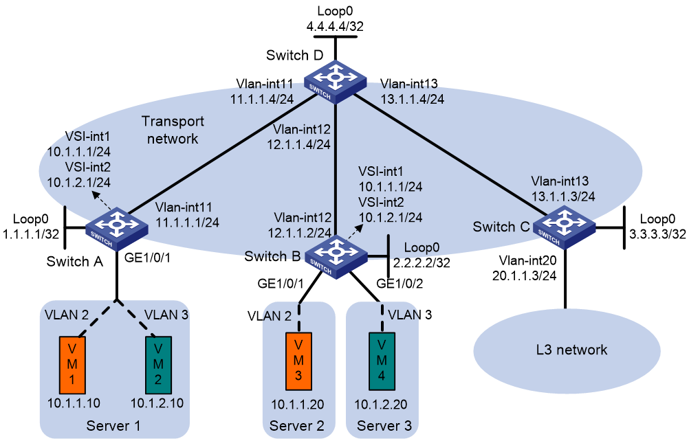
Procedure
1. On VM 1 and VM 3, specify 10.1.1.1 as the gateway address. On VM 2 and VM 4, specify 10.1.2.1 as the gateway address. (Details not shown.)
2. Configure IP addresses and unicast routing settings:
# Assign IP addresses to interfaces, as shown in Figure 11. (Details not shown.)
# Configure OSPF on all transport network switches (Switches A through D) for them to reach one another. (Details not shown.)
3. Configure Switch A:
# Enable L2VPN and IP multicast routing.
<SwitchA> system-view
[SwitchA] l2vpn enable
[SwitchA] multicast routing
[SwitchA-mrib] quit
# Enable the IGMP snooping feature.
[SwitchA] igmp-snooping
[SwitchA-igmp-snooping] quit
# Disable remote MAC address learning and remote ARP learning.
[SwitchA] vxlan tunnel mac-learning disable
[SwitchA] vxlan tunnel arp-learning disable
# Create VLAN-interface 11 and enter its view.
[SwitchA] vlan 11
[SwitchA-vlan11] quit
[SwitchA] interface vlan-interface 11
# Enable PIM-SM on VLAN-interface 11.
[SwitchA-Vlan-interface11] pim sm
[SwitchA-Vlan-interface11] quit
# Create an EVPN instance on VSI vpna.
[SwitchA] vsi vpna
[SwitchA-vsi-vpna] evpn encapsulation vxlan
[SwitchA-vsi-vpna-evpn-vxlan] route-distinguisher auto
[SwitchA-vsi-vpna-evpn-vxlan] vpn-target auto export-extcommunity
[SwitchA-vsi-vpna-evpn-vxlan] vpn-target auto import-extcommunity
[SwitchA-vsi-vpna-evpn-vxlan] quit
# Enable IGMP snooping and IGMP snooping proxying on VSI vpna.
[SwitchA-vsi-vpna] igmp-snooping enable
[SwitchA-vsi-vpna] igmp-snooping proxy enable
# Create VXLAN 10.
[SwitchA-vsi-vpna] vxlan 10
[SwitchA-vsi-vpna-vxlan-10] quit
[SwitchA-vsi-vpna] quit
# Create an EVPN instance on VSI vpnb.
[SwitchA] vsi vpnb
[SwitchA-vsi-vpnb] evpn encapsulation vxlan
[SwitchA-vsi-vpnb-evpn-vxlan] route-distinguisher auto
[SwitchA-vsi-vpnb-evpn-vxlan] vpn-target auto export-extcommunity
[SwitchA-vsi-vpnb-evpn-vxlan] vpn-target auto import-extcommunity
[SwitchA-vsi-vpnb-evpn-vxlan] quit
# Enable IGMP snooping and IGMP snooping proxying on VSI vpnb.
[SwitchA-vsi-vpnb] igmp-snooping enable
[SwitchA-vsi-vpnb] igmp-snooping proxy enable
# Create VXLAN 20.
[SwitchA-vsi-vpnb] vxlan 20
[SwitchA-vsi-vpnb-vxlan-20] quit
[SwitchA-vsi-vpnb] quit
# Configure BGP to advertise BGP EVPN routes.
[SwitchA] bgp 200
[SwitchA-bgp-default] peer 4.4.4.4 as-number 200
[SwitchA-bgp-default] peer 4.4.4.4 connect-interface loopback 0
[SwitchA-bgp-default] address-family l2vpn evpn
[SwitchA-bgp-default-evpn] peer 4.4.4.4 enable
[SwitchA-bgp-default-evpn] quit
[SwitchA-bgp-default] quit
# Create VLAN 2.
[SwitchA] vlan 2
[SwitchA-vlan2] quit
# Create VLAN 3.
[SwitchA] vlan 3
[SwitchA-vlan3] quit
# Configure GigabitEthernet 1/0/1 as a trunk port and assign it to VLAN 2 and VLAN 3.
[SwitchA] interface gigabitethernet 1/0/1
[SwitchA-GigabitEthernet1/0/1] port link-type trunk
[SwitchA-GigabitEthernet1/0/1] port trunk permit vlan 2 3
# On GigabitEthernet 1/0/1, create Ethernet service instance 1000 to match VLAN 2.
[SwitchA-GigabitEthernet1/0/1] service-instance 1000
[SwitchA-GigabitEthernet1/0/1-srv1000] encapsulation s-vid 2
# Map Ethernet service instance 1000 to VSI vpna.
[SwitchA-GigabitEthernet1/0/1-srv1000] xconnect vsi vpna
[SwitchA-GigabitEthernet1/0/1-srv1000] quit
# On GigabitEthernet 1/0/1, create Ethernet service instance 2000 to match VLAN 3.
[SwitchA-GigabitEthernet1/0/1] service-instance 2000
[SwitchA-GigabitEthernet1/0/1-srv2000] encapsulation s-vid 3
# Map Ethernet service instance 2000 to VSI vpnb.
[SwitchA-GigabitEthernet1/0/1-srv2000] xconnect vsi vpnb
[SwitchA-GigabitEthernet1/0/1-srv2000] quit
[SwitchA-GigabitEthernet1/0/1] quit
# Configure RD and route target settings for VPN instance vpna.
[SwitchA] ip vpn-instance vpna
[SwitchA-vpn-instance-vpna] route-distinguisher 1:1
[SwitchA-vpn-instance-vpna] address-family ipv4
[SwitchA-vpn-ipv4-vpna] vpn-target 1:1
[SwitchA-vpn-ipv4-vpna] quit
[SwitchA-vpn-instance-vpna] address-family evpn
[SwitchA-vpn-evpn-vpna] vpn-target 1:1
[SwitchA-vpn-evpn-vpna] quit
[SwitchA-vpn-instance-vpna] quit
# Configure VSI-interface 1.
[SwitchA] interface vsi-interface 1
[SwitchA-Vsi-interface1] ip binding vpn-instance vpna
[SwitchA-Vsi-interface1] ip address 10.1.1.1 255.255.255.0
[SwitchA-Vsi-interface1] pim sm
[SwitchA-Vsi-interface1] pim distributed-dr
[SwitchA-Vsi-interface1] mac-address 1-1-1
[SwitchA-Vsi-interface1] distributed-gateway local
[SwitchA-Vsi-interface1] local-proxy-arp enable
[SwitchA-Vsi-interface1] quit
# Configure VSI-interface 2.
[SwitchA] interface vsi-interface 2
[SwitchA-Vsi-interface2] ip binding vpn-instance vpna
[SwitchA-Vsi-interface2] ip address 10.1.2.1 255.255.255.0
[SwitchA-Vsi-interface2] igmp enable
[SwitchA-Vsi-interface2] mac-address 2-2-2
[SwitchA-Vsi-interface2] distributed-gateway local
[SwitchA-Vsi-interface2] local-proxy-arp enable
[SwitchA-Vsi-interface2] quit
# Associate VSI-interface 3 with VPN instance vpna, and configure the L3 VXLAN ID as 1000 for the VPN instance.
[SwitchA] interface vsi-interface 3
[SwitchA-Vsi-interface3] ip binding vpn-instance vpna
[SwitchA-Vsi-interface3] l3-vni 1000
[SwitchA-Vsi-interface3] pim sm
[SwitchA-Vsi-interface3] quit
# Enable IP multicast routing for VPN instance vpna.
[SwitchA] multicast routing vpn-instance vpna
[SwitchA-mrib-vpna] quit
# Create an MDT-based MVXLAN for VPN instance vpna and enter MVXLAN IPv4 address family view. Configure the default group, MVXLAN source interface, and data group range settings.
[SwitchA] multicast-vpn vxlan vpn-instance vpna mode mdt
[SwitchA-mvxlan-vpna] address-family ipv4
[SwitchA-mvxlan-vpna-ipv4] default-group 236.0.0.1
[SwitchA-mvxlan-vpna-ipv4] source loopback 0
[SwitchA-mvxlan-vpna-ipv4] data-group 239.0.1.0 30
[SwitchA-mvxlan-vpna-ipv4] quit
[SwitchA-mvxlan-vpna] quit
# Configure Loopback 1.
[SwitchA] interface loopback 1
[SwitchA-LoopBack1] ip binding vpn-instance vpna
[SwitchA-LoopBack1] ip address 12.12.12.12 32
[SwitchA-LoopBack1] pim sm
[SwitchA-LoopBack1] quit
# Enter VPN instance PIM view, and configure Loopback 1 as a candidate-BSR and candidate-RP in VPN instance vpna.
[SwitchA] pim vpn-instance vpna
[SwitchA-pim-vpna] c-bsr 12.12.12.12
[SwitchA-pim-vpna] c-rp 12.12.12.12
[SwitchA-pim-vpna] quit
# Specify VSI-interface 1 as the gateway interface for VSI vpna.
[SwitchA] vsi vpna
[SwitchA-vsi-vpna] gateway vsi-interface 1
[SwitchA-vsi-vpna] quit
# Specify VSI-interface 2 as the gateway interface for VSI vpnb.
[SwitchA] vsi vpnb
[SwitchA-vsi-vpnb] gateway vsi-interface 2
[SwitchA-vsi-vpnb] quit
4. Configure Switch B:
# Enable L2VPN and IP multicast routing.
<SwitchB> system-view
[SwitchB] l2vpn enable
[SwitchB] multicast routing
[SwitchB-mrib] quit
# Enable the IGMP snooping feature.
[SwitchB] igmp-snooping
[SwitchB-igmp-snooping] quit
# Disable remote MAC address learning and remote ARP learning.
[SwitchB] vxlan tunnel mac-learning disable
[SwitchB] vxlan tunnel arp-learning disable
# Create VLAN-interface 12 and enter its view.
[SwitchB] vlan 12
[SwitchB-vlan12] quit
[SwitchB] interface vlan-interface 12
# Enable PIM-SM on VLAN-interface 12.
[SwitchB-Vlan-interface12] pim sm
[SwitchB-Vlan-interface12] quit
# Create an EVPN instance on VSI vpna.
[SwitchB] vsi vpna
[SwitchB-vsi-vpna] evpn encapsulation vxlan
[SwitchB-vsi-vpna-evpn-vxlan] route-distinguisher auto
[SwitchB-vsi-vpna-evpn-vxlan] vpn-target auto export-extcommunity
[SwitchB-vsi-vpna-evpn-vxlan] vpn-target auto import-extcommunity
[SwitchB-vsi-vpna-evpn-vxlan] quit
# Enable IGMP snooping and IGMP snooping proxying on VSI vpna
[SwitchB-vsi-vpna] igmp-snooping enable
[SwitchB-vsi-vpna] igmp-snooping proxy enable
# Create VXLAN 10.
[SwitchB-vsi-vpna] vxlan 10
[SwitchB-vsi-vpna-vxlan-10] quit
[SwitchB-vsi-vpna] quit
# Create an EVPN instance on VSI vpnb.
[SwitchB] vsi vpnb
[SwitchB-vsi-vpnb] evpn encapsulation vxlan
[SwitchB-vsi-vpnb-evpn-vxlan] route-distinguisher auto
[SwitchB-vsi-vpnb-evpn-vxlan] vpn-target auto export-extcommunity
[SwitchB-vsi-vpnb-evpn-vxlan] vpn-target auto import-extcommunity
[SwitchB-vsi-vpnb-evpn-vxlan] quit
# Enable IGMP snooping and IGMP snooping proxying on VSI vpnb.
[SwitchB-vsi-vpnb] igmp-snooping enable
[SwitchB-vsi-vpnb] igmp-snooping proxy enable
# Create VXLAN 20.
[SwitchB-vsi-vpnb] vxlan 20
[SwitchB-vsi-vpnb-vxlan-20] quit
[SwitchB-vsi-vpnb] quit
# Configure BGP to advertise BGP EVPN routes.
[SwitchB] bgp 200
[SwitchB-bgp-default] peer 4.4.4.4 as-number 200
[SwitchB-bgp-default] peer 4.4.4.4 connect-interface loopback 0
[SwitchB-bgp-default] address-family l2vpn evpn
[SwitchB-bgp-default-evpn] peer 4.4.4.4 enable
[SwitchB-bgp-default-evpn] quit
[SwitchB-bgp-default] quit
# Create VLAN 2.
[SwitchB] vlan 2
[SwitchB-vlan2] quit
# Create VLAN 3.
[SwitchB] vlan 3
[SwitchB-vlan3] quit
# Configure GigabitEthernet 1/0/1 as a trunk port and assign it to VLAN 2.
[SwitchB] interface gigabitethernet 1/0/1
[SwitchB-GigabitEthernet1/0/1] port link-type trunk
[SwitchB-GigabitEthernet1/0/1] port trunk permit vlan 2
# On GigabitEthernet 1/0/1, create Ethernet service instance 1000 to match VLAN 2.
[SwitchB] interface gigabitethernet 1/0/1
[SwitchB-GigabitEthernet1/0/1] service-instance 1000
[SwitchB-GigabitEthernet1/0/1-srv1000]encapsulation s-vid 2
# Map Ethernet service instance 1000 to VSI vpna.
[SwitchB-GigabitEthernet1/0/1-srv1000] xconnect vsi vpna
[SwitchB-GigabitEthernet1/0/1-srv1000] quit
# Configure GigabitEthernet 1/0/2 as a trunk port and assign it to VLAN 3.
[SwitchB] interface gigabitethernet 1/0/2
[SwitchB-GigabitEthernet1/0/2] port link-type trunk
[SwitchB-GigabitEthernet1/0/2] port trunk permit vlan 3
# On GigabitEthernet 1/0/2, create Ethernet service instance 2000 to match VLAN 3.
[SwitchB-GigabitEthernet1/0/2] service-instance 2000
[SwitchB-GigabitEthernet1/0/2-srv2000] encapsulation s-vid 3
# Map Ethernet service instance 2000 to VSI vpnb.
[SwitchB-GigabitEthernet1/0/2-srv2000] xconnect vsi vpnb
[SwitchB-GigabitEthernet1/0/2-srv2000] quit
[SwitchB-GigabitEthernet1/0/2] quit
# Configure RD and route target settings for VPN instance vpna.
[SwitchB] ip vpn-instance vpna
[SwitchB-vpn-instance-vpna] route-distinguisher 1:1
[SwitchB-vpn-instance-vpna] address-family ipv4
[SwitchB-vpn-ipv4-vpna] vpn-target 1:1
[SwitchB-vpn-ipv4-vpna] quit
[SwitchB-vpn-instance-vpna] address-family evpn
[SwitchB-vpn-evpn-vpna] vpn-target 1:1
[SwitchB-vpn-evpn-vpna] quit
[SwitchB-vpn-instance-vpna] quit
# Configure RD and route target settings for VPN instance vpnb.
[SwitchB] ip vpn-instance vpnb
[SwitchB-vpn-instance-vpnb] route-distinguisher 2:2
[SwitchB-vpn-instance-vpnb] address-family ipv4
[SwitchB-vpn-ipv4-vpnb] vpn-target 1:1
[SwitchB-vpn-ipv4-vpnb] quit
[SwitchB-vpn-instance-vpnb] address-family evpn
[SwitchB-vpn-evpn-vpnb] vpn-target 1:1
[SwitchB-vpn-evpn-vpnb] quit
[SwitchB-vpn-instance-vpnb] quit
# Configure VSI-interface 1.
[SwitchB] interface vsi-interface 1
[SwitchB-Vsi-interface1] ip binding vpn-instance vpna
[SwitchB-Vsi-interface1] ip address 10.1.1.1 255.255.255.0
[SwitchB-Vsi-interface1] igmp enable
[SwitchB-Vsi-interface1] mac-address 1-1-1
[SwitchB-Vsi-interface1] distributed-gateway local
[SwitchB-Vsi-interface1] local-proxy-arp enable
[SwitchB-Vsi-interface1] quit
# Configure VSI-interface 2.
[SwitchB] interface vsi-interface 2
[SwitchB-Vsi-interface2] ip binding vpn-instance vpnb
[SwitchB-Vsi-interface2] ip address 10.1.2.1 255.255.255.0
[SwitchB-Vsi-interface2] igmp enable
[SwitchB-Vsi-interface2] mac-address 2-2-2
[SwitchB-Vsi-interface2] distributed-gateway local
[SwitchB-Vsi-interface2] local-proxy-arp enable
[SwitchB-Vsi-interface2] quit
# Associate VSI-interface 3 with VPN instance vpna, and configure the L3 VXLAN ID as 1000 for the VPN instance.
[SwitchB] interface vsi-interface 3
[SwitchB-Vsi-interface3] ip binding vpn-instance vpna
[SwitchB-Vsi-interface3] l3-vni 1000
[SwitchB-Vsi-interface3] pim sm
[SwitchB-Vsi-interface3] quit
# Enable IP multicast routing for VPN instance vpna.
[SwitchB] multicast routing vpn-instance vpna
[SwitchB-mrib-vpna] quit
# Enable IP multicast routing for VPN instance vpnb.
[SwitchB] multicast routing vpn-instance vpnb
[SwitchB-mrib-vpnb] quit
# Create an MDT-based MVXLAN for VPN instance vpna, enter MVXLAN IPv4 address family view, and configure the MVXLAN source interface.
[SwitchB] multicast-vpn vxlan vpn-instance vpna mode mdt
[SwitchB-mvxlan-vpna] address-family ipv4
[SwitchB-mvxlan-vpna-ipv4] source loopback 0
[SwitchB-mvxlan-vpna-ipv4] quit
[SwitchB-mvxlan-vpna] quit
# Configure Loopback 1.
[SwitchB] interface loopback 1
[SwitchB-LoopBack1] ip binding vpn-instance vpna
[SwitchB-LoopBack1] ip address 12.12.12.12 32
[SwitchB-LoopBack1] pim sm
[SwitchB-LoopBack1] quit
# Enter VPN instance PIM view, and configure Loopback 1 as a candidate-BSR and candidate-RP in VPN instance vpna.
[SwitchB] pim vpn-instance vpna
[SwitchB-pim-vpna] c-bsr 12.12.12.12
[SwitchB-pim-vpna] c-rp 12.12.12.12
[SwitchB-pim-vpna] quit
# Configure Loopback 2.
[SwitchB] interface loopback 2
[SwitchB-LoopBack2] ip binding vpn-instance vpnb
[SwitchB-LoopBack2] ip address 13.13.13.13 32
[SwitchB-LoopBack2] pim sm
[SwitchB-LoopBack2] quit
# Enter VPN instance PIM view, and configure Loopback 2 as a candidate-BSR and candidate-RP in VPN instance vpnb.
[SwitchB] pim vpn-instance vpnb
[SwitchB-pim-vpnb] c-bsr 13.13.13.13
[SwitchB-pim-vpnb] c-rp 13.13.13.13
[SwitchB-pim-vpnb] quit
# Specify VSI-interface 1 as the gateway interface for VSI vpna.
[SwitchB] vsi vpna
[SwitchB-vsi-vpna] gateway vsi-interface 1
[SwitchB-vsi-vpna] quit
# Specify VSI-interface 2 as the gateway interface for VSI vpnb.
[SwitchB] vsi vpnb
[SwitchB-vsi-vpnb] gateway vsi-interface 2
[SwitchB-vsi-vpnb] quit
# Enable IP multicast routing for VPN instance vpnb, and import the traffic of VPN instance vpna to VPN instance vpnb.
[SwitchB] multicast routing vpn-instance vpnb
[SwitchB-mrib-vpnb] multicast extranet select-rpf l3-vni 1000 group 225.0.0.0 16
[SwitchB-mrib-vpnb] quit
5. Configure Switch C:
# Enable L2VPN and IP multicast routing.
<SwitchC> system-view
[SwitchC] l2vpn enable
[SwitchC] multicast routing
[SwitchC-mrib] quit
# Disable remote MAC address learning and remote ARP learning.
[SwitchC] vxlan tunnel mac-learning disable
[SwitchC] vxlan tunnel arp-learning disable
# Create VLAN-interface 13 and enter its view.
[SwitchC] vlan 13
[SwitchC-vlan13] quit
[SwitchC] interface vlan-interface 13
# Enable PIM-SM on VLAN-interface 13.
[SwitchC-Vlan-interface13] pim sm
[SwitchC-Vlan-interface13] quit
# Configure BGP to advertise BGP EVPN routes.
[SwitchC] bgp 200
[SwitchC-bgp-default] peer 4.4.4.4 as-number 200
[SwitchC-bgp-default] peer 4.4.4.4 connect-interface loopback 0
[SwitchC-bgp-default] address-family l2vpn evpn
[SwitchC-bgp-default-evpn] peer 4.4.4.4 enable
[SwitchC-bgp-default-evpn] quit
[SwitchC-bgp-default] quit
# Configure RD and route target settings for VPN instance vpna.
[SwitchC] ip vpn-instance vpna
[SwitchC-vpn-instance-vpna] route-distinguisher 1:1
[SwitchC-vpn-instance-vpna] address-family ipv4
[SwitchC-vpn-ipv4-vpna] vpn-target 1:1
[SwitchC-vpn-ipv4-vpna] quit
[SwitchC-vpn-instance-vpna] address-family evpn
[SwitchC-vpn-evpn-vpna] vpn-target 1:1
[SwitchC-vpn-evpn-vpna] quit
[SwitchC-vpn-instance-vpna] quit
# Configure RD and route target settings for VPN instance vpnb.
[SwitchC] ip vpn-instance vpnb
[SwitchC-vpn-instance-vpna] route-distinguisher 2:2
[SwitchC-vpn-instance-vpna] address-family ipv4
[SwitchC-vpn-ipv4-vpna] vpn-target 1:1
[SwitchC-vpn-ipv4-vpna] quit
[SwitchC-vpn-instance-vpna] address-family evpn
[SwitchC-vpn-evpn-vpna] vpn-target 1:1
[SwitchC-vpn-evpn-vpna] quit
[SwitchC-vpn-instance-vpna] quit
# Associate VSI-interface 3 with VPN instance vpna, and configure the L3 VXLAN ID as 1000 for the VPN instance.
[SwitchC] interface vsi-interface 3
[SwitchC-Vsi-interface3] ip binding vpn-instance vpna
[SwitchC-Vsi-interface3] l3-vni 1000
[SwitchC-Vsi-interface3] pim sm
[SwitchC-Vsi-interface3] quit
# Enable IP multicast routing for VPN instance vpna.
[SwitchC] multicast routing vpn-instance vpna
[SwitchC-mrib-vpna] quit
# Enable IP multicast routing for VPN instance vpnb.
[SwitchC] multicast routing vpn-instance vpnb
[SwitchC-mrib-vpnb] quit
# Create an MDT-based MVXLAN for VPN instance vpna, enter MVXLAN IPv4 address family view, and configure the MVXLAN source interface.
[SwitchC] multicast-vpn vxlan vpn-instance vpna mode mdt
[SwitchC-mvxlan-vpna] address-family ipv4
[SwitchC-mvxlan-vpna-ipv4] source loopback 0
[SwitchC-mvxlan-vpna-ipv4] quit
[SwitchC-mvxlan-vpna] quit
# Configure Loopback 1.
[SwitchC] interface loopback 1
[SwitchC-LoopBack1] ip binding vpn-instance vpna
[SwitchC-LoopBack1] ip address 12.12.12.12 32
[SwitchC-LoopBack1] pim sm
[SwitchC-LoopBack1] quit
# Enter VPN instance PIM view, and configure Loopback 1 as a candidate-BSR and candidate-RP in VPN instance vpna.
[SwitchC] pim vpn-instance vpna
[SwitchC-pim-vpna] c-bsr 12.12.12.12
[SwitchC-pim-vpna] c-rp 12.12.12.12
[SwitchC-pim-vpna] quit
# Configure Loopback 2.
[SwitchC] interface loopback 2
[SwitchC-LoopBack2] ip binding vpn-instance vpnb
[SwitchC-LoopBack2] ip address 13.13.13.13 32
[SwitchC-LoopBack2] pim sm
[SwitchC-LoopBack2] quit
# Enter VPN instance PIM view, and configure Loopback 2 as a candidate-BSR and candidate-RP in VPN instance vpnb.
[SwitchC] pim vpn-instance vpnb
[SwitchC-pim-vpnb] c-bsr 13.13.13.13
[SwitchC-pim-vpnb] c-rp 13.13.13.13
[SwitchC-pim-vpnb] quit
# Configure a default route. Specify the next hop as 20.1.1.100, the IP address of a device in the Layer 3 network.
[SwitchC] ip route-static vpn-instance vpnb 0.0.0.0 0 20.1.1.100
# Import the default route to the BGP IPv4 unicast routing table of VPN instance vpnb.
[SwitchC] bgp 200
[SwitchC-bgp-default] ip vpn-instance vpnb
[SwitchC-bgp-default-vpnb] address-family ipv4 unicast
[SwitchC-bgp-default-ipv4-vpnb] default-route imported
[SwitchC-bgp-default-ipv4-vpnb] import-route static
[SwitchC-bgp-default-ipv4-vpnb] quit
[SwitchC-bgp-default-vpnb] quit
[SwitchC-bgp-default] quit
# Create VLAN 20.
[SwitchC] vlan 20
[SwitchC-vlan20] quit
# Configure VLAN-interface 20 that connects to the Layer 3 network and associate the interface with VPN instance vpnb.
[SwitchC] interface vlan-interface 20
[SwitchC-Vlan-interface20] ip binding vpn-instance vpnb
[SwitchC-Vlan-interface20] ip address 20.1.1.3 24
[SwitchC-Vlan-interface20] pim sm
[SwitchC-Vlan-interface20] quit
# Enable IP multicast routing for VPN instance vpnb, and import the traffic of VPN instance vpna to VPN instance vpnb.
[SwitchC] multicast routing vpn-instance vpnb
[SwitchC-mrib-vpnb] multicast extranet select-rpf l3-vni 1000 group 225.0.0.0 16
[SwitchC-mrib-vpnb] quit
6. Configure Switch D:
# Enable IP multicast routing.
<SwitchD> system-view
[SwitchD] multicast routing
[SwitchD-mrib] quit
# Enter PIM view, and configure Loopback 0 as a candidate-BSR and candidate-RP in the public network.
[SwitchD] pim
[SwitchD-pim] c-bsr 4.4.4.4
[SwitchD-pim] c-rp 4.4.4.4
[SwitchD-pim] quit
# Enable PIM-SM on VLAN-interface 11.
[SwitchD] interface vlan-interface11
[SwitchD-Vlan-interface11] pim sm
[SwitchD-Vlan-interface11] quit
# Enable PIM-SM on VLAN-interface 12.
[SwitchD] interface vlan-interface12
[SwitchD-Vlan-interface12] pim sm
[SwitchD-Vlan-interface12] quit
# Enable PIM-SM on VLAN-interface 13.
[SwitchD] interface vlan-interface13
[SwitchD-Vlan-interface13] pim sm
[SwitchD-Vlan-interface13] quit
# Establish BGP connections with other transport network switches.
[SwitchD] bgp 200
[SwitchD-bgp-default] group evpn
[SwitchD-bgp-default] peer 1.1.1.1 group evpn
[SwitchD-bgp-default] peer 2.2.2.2 group evpn
[SwitchD-bgp-default] peer 3.3.3.3 group evpn
[SwitchD-bgp-default] peer evpn as-number 200
[SwitchD-bgp-default] peer evpn connect-interface loopback 0
# Configure BGP to advertise BGP EVPN routes, and disable route target filtering of received BGP EVPN routes.
[SwitchD-bgp-default] address-family l2vpn evpn
[SwitchD-bgp-default-evpn] peer evpn enable
[SwitchD-bgp-default-evpn] undo policy vpn-target
# Configure Switch D as an RR.
[SwitchD-bgp-default-evpn] peer evpn reflect-client
[SwitchD-bgp-default-evpn] quit
[SwitchD-bgp-default] quit
Verifying the configuration
1. Verify the multicast routing information on Switch A:
# Verify that Switch A has multicast routing entries for VPN instance vpna.
<SwitchA> display pim vpn-instance vpna routing-table
Total 1 (*, G) entries; 1 (S, G) entries
(*, 225.0.0.0)
RP: 12.12.12.12 (local)
Protocol: pim-sm, Flag: WC RC
UpTime: 03:01:20
Upstream interface: Register-Tunnel0
Upstream neighbor: NULL
RPF prime neighbor: NULL
Downstream interface information:
Total number of downstream interfaces: 1
1: MTunnel0
Protocol: MD, UpTime: 02:57:31, Expires: -
2: Vsi-interface2
Protocol: igmp, UpTime: 03:01:22, Expires: -
(10.1.1.10, 225.0.0.0)
RP: 12.12.12.12 (local)
Protocol: pim-sm, Flag: SPT 2MSDP LOC ACT SQ RC 2MVPN
UpTime: 03:01:20
Upstream interface: Vsi-interface1
Upstream neighbor: NULL
RPF prime neighbor: NULL
Downstream interface information:
Total number of downstream interfaces: 1
1: MTunnel1
Protocol: MD, UpTime: 02:56:31, Expires: -
2: Vsi-interface2
Protocol: igmp, UpTime: 03:01:22, Expires: -
# Verify that Switch A has multicast routing entries for the public network.
<SwitchA> display pim routing-table
Total 0 (*, G) entries; 2 (S, G) entries
(1.1.1.1, 236.0.0.1)
RP: 4.4.4.4
Protocol: pim-sm, Flag: SPT LOC VXLAN_L3
UpTime: 04:09:52
Upstream interface: MTunnel0 (VPN: vpna)
Upstream neighbor: NULL
RPF prime neighbor: NULL
Downstream interface information:
Total number of downstream interfaces: 1
1: Vlan-interface11
Protocol: pim-sm, UpTime: 04:09:40, Expires: 00:03:10
(1.1.1.1, 239.0.1.0)
RP: 4.4.4.4
Protocol: pim-sm, Flag: SPT LOC VXLAN_L3
UpTime: 03:00:20
Upstream interface: MTunnel1 (VPN: vpna)
Upstream neighbor: NULL
RPF prime neighbor: NULL
Downstream interface information:
Total number of downstream interfaces: 1
1: Vlan-interface11
Protocol: pim-sm, UpTime: 03:00:20, Expires: 00:03:11
2. Verify the multicast routing information on Switch B:
# Verify that Switch B has multicast routing entries for VPN instance vpna.
<SwitchB> display pim vpn-instance vpna routing-table
Total 1 (*, G) entries; 1 (S, G) entries
(*, 225.0.0.0)
RP: 12.12.12.12 (local)
Protocol: pim-sm, Flag: WC
UpTime: 03:01:20
Upstream interface: Register-Tunnel0
Upstream neighbor: NULL
RPF prime neighbor: NULL
Downstream interface information:
Total number of downstream interfaces: 2
1: Extranet (VPN: vpnb)
Protocol: MD, UpTime: 03:01:20, Expires: -
2: Vsi-interface1
Protocol: igmp, UpTime: 03:01:20, Expires: -
(10.1.1.10, 225.0.0.0)
RP: 12.12.12.12 (local)
Protocol: pim-sm, Flag: SPT ACT FROMVXLAN
UpTime: 03:00:20
Upstream interface: MVXLAN-UPE0 (0.0.0.0)
Upstream neighbor: NULL
RPF prime neighbor: NULL
Downstream interface information:
Total number of downstream interfaces: 2
1: Extranet (VPN: vpnb)
Protocol: MD, UpTime: 03:00:20, Expires: -
2: Vsi-interface1
Protocol: pim-sm, UpTime: 03:00:20, Expires: -
# Verify that Switch B has multicast routing entries for VPN instance vpnb.
<SwitchB> display pim vpn-instance vpnb routing-table
Total 1 (*, G) entries; 1 (S, G) entries
(*, 225.0.0.0)
RP: 13.13.13.13 (local)
Protocol: pim-sm, Flag: WC
UpTime: 03:01:20
Upstream interface: Extranet (VPN: vpna, l3-vni: 1000)
Upstream neighbor: 127.0.0.1
RPF prime neighbor: 127.0.0.1
Downstream interface information:
Total number of downstream interfaces: 1
1: Vsi-interface2
Protocol: igmp, UpTime: 05:04:11, Expires: -
(10.1.1.10, 225.0.0.0)
RP: 13.13.13.13 (local)
Protocol: pim-sm, Flag: SPT ACT RQ 2MVPN
UpTime: 03:00:20
Upstream interface: Extranet (VPN: vpna, l3-vni: 1000)
Upstream neighbor: 127.0.0.1
RPF prime neighbor: 127.0.0.1
Downstream interface information:
Total number of downstream interfaces: 1
1: Vsi-interface2
Protocol: pim-sm, UpTime: 03:00:20, Expires: -
# Verify that Switch B has multicast routing entries for the public network.
<SwitchB> display pim routing-table
Total 0 (*, G) entries; 2 (S, G) entries
(1.1.1.1, 236.0.0.1)
RP: 4.4.4.4
Protocol: pim-sm, Flag: SPT
UpTime: 04:09:00
Upstream interface: Vlan-interface12
Upstream neighbor: 12.1.1.4
RPF prime neighbor: 12.1.1.4
Downstream interface information:
Total number of downstream interfaces: 1
1: MVXLAN-UPE0
Protocol: MD, UpTime: 04:09:40, Expires: -
(1.1.1.1, 239.0.1.0)
RP: 4.4.4.4
Protocol: pim-sm, Flag: SPT ACT 2MVPN
UpTime: 03:00:20
Upstream interface: Vlan-interface12
Upstream neighbor: 12.1.1.4
RPF prime neighbor: 12.1.1.4
Downstream interface information:
Total number of downstream interfaces: 1
1: MVXLAN-UPE0
Protocol: MD, UpTime: 03:00:20, Expires: -
Example: Configuring MVXLAN extranet on the receiver VPN instance for asymmetrically configured extranet
Network configuration
As shown in Figure 12, VM 1 is the multicast source of multicast group 225.0.0.0, and the other VMs are multicast receivers. VM 1 and VM 2 belong to VPN instance vpna, VM 3 belongs to VPN instance vpnb, and VM 4 belongs to vpnc. VM 1 and VM 3 are in VXLAN 10, and VM 2 and VM 4 are in VXLAN 20. Configure MVXLAN to forward the multicast traffic from the source to the receivers.
· Configure VXLAN 10 and VXLAN 20 on Switch A and Switch B to extend VLAN 2 and VLAN 3 across the sites.
· Configure Switch A and Switch B as distributed EVPN gateways to provide gateway services. Configure Switch C as a border gateway to provide access to the connected Layer 3 network.
· Configure Switch D as an RR to reflect BGP EVPN routes between Switch A, Switch B, and Switch C.
· Configure PIM-SM on the transport-facing interfaces of Switches A through D. Configure IGMP snooping on Switches A through C for multicast forwarding entry creation.
· Configure MVXLAN extranet to import the traffic of VPN instance vpna to VPN instance vpnb and VPN instance vpnc based on the L3 VXLAN ID on Switch B.

Procedure
1. On VM 1 and VM 3, specify 10.1.1.1 as the gateway address. On VM 2 and VM 4, specify 10.1.2.1 as the gateway address. (Details not shown.)
2. Configure IP addresses and unicast routing settings:
# Assign IP addresses to interfaces, as shown in Figure 12. (Details not shown.)
# Configure OSPF on all transport network switches (Switches A through D) for them to reach one another. (Details not shown.)
3. Configure Switch A:
# Enable L2VPN and IP multicast routing.
<SwitchA> system-view
[SwitchA] l2vpn enable
[SwitchA] multicast routing
[SwitchA-mrib] quit
# Enable the IGMP snooping feature.
[SwitchA] igmp-snooping
[SwitchA-igmp-snooping] quit
# Disable remote MAC address learning and remote ARP learning.
[SwitchA] vxlan tunnel mac-learning disable
[SwitchA] vxlan tunnel arp-learning disable
# Create VLAN-interface 11 and enter its view.
[SwitchA] vlan 11
[SwitchA-vlan11] quit
[SwitchA] interface vlan-interface 11
# Enable PIM-SM on VLAN-interface 11.
[SwitchA-Vlan-interface11] pim sm
[SwitchA-Vlan-interface11] quit
# Create an EVPN instance on VSI vpna.
[SwitchA] vsi vpna
[SwitchA-vsi-vpna] evpn encapsulation vxlan
[SwitchA-vsi-vpna-evpn-vxlan] route-distinguisher auto
[SwitchA-vsi-vpna-evpn-vxlan] vpn-target auto export-extcommunity
[SwitchA-vsi-vpna-evpn-vxlan] vpn-target auto import-extcommunity
[SwitchA-vsi-vpna-evpn-vxlan] quit
# Enable IGMP snooping and IGMP snooping proxying on VSI vpna.
[SwitchA-vsi-vpna] igmp-snooping enable
[SwitchA-vsi-vpna] igmp-snooping proxy enable
# Create VXLAN 10.
[SwitchA-vsi-vpna] vxlan 10
[SwitchA-vsi-vpna-vxlan-10] quit
[SwitchA-vsi-vpna] quit
# Create an EVPN instance on VSI vpnb.
[SwitchA] vsi vpnb
[SwitchA-vsi-vpnb] evpn encapsulation vxlan
[SwitchA-vsi-vpnb-evpn-vxlan] route-distinguisher auto
[SwitchA-vsi-vpnb-evpn-vxlan] vpn-target auto export-extcommunity
[SwitchA-vsi-vpnb-evpn-vxlan] vpn-target auto import-extcommunity
[SwitchA-vsi-vpnb-evpn-vxlan] quit
# Enable IGMP snooping and IGMP snooping proxying on VSI vpnb.
[SwitchA-vsi-vpnb] igmp-snooping enable
[SwitchA-vsi-vpnb] igmp-snooping proxy enable
# Create VXLAN 20.
[SwitchA-vsi-vpnb] vxlan 20
[SwitchA-vsi-vpnb-vxlan-20] quit
[SwitchA-vsi-vpnb] quit
# Configure BGP to advertise BGP EVPN routes.
[SwitchA] bgp 200
[SwitchA-bgp-default] peer 4.4.4.4 as-number 200
[SwitchA-bgp-default] peer 4.4.4.4 connect-interface loopback 0
[SwitchA-bgp-default] address-family l2vpn evpn
[SwitchA-bgp-default-evpn] peer 4.4.4.4 enable
[SwitchA-bgp-default-evpn] quit
[SwitchA-bgp-default] quit
# Create VLAN 2.
[SwitchA] vlan 2
[SwitchA-vlan2] quit
# Create VLAN 3.
[SwitchA] vlan 3
[SwitchA-vlan3] quit
# Configure GigabitEthernet 1/0/1 as a trunk port and assign it to VLAN 2 and VLAN 3.
[SwitchA] interface gigabitethernet 1/0/1
[SwitchA-GigabitEthernet1/0/1] port link-type trunk
[SwitchA-GigabitEthernet1/0/1] port trunk permit vlan 2 3
# On GigabitEthernet 1/0/1, create Ethernet service instance 1000 to match VLAN 2.
[SwitchA-GigabitEthernet1/0/1] service-instance 1000
[SwitchA-GigabitEthernet1/0/1-srv1000] encapsulation s-vid 2
# Map Ethernet service instance 1000 to VSI vpna.
[SwitchA-GigabitEthernet1/0/1-srv1000] xconnect vsi vpna
[SwitchA-GigabitEthernet1/0/1-srv1000] quit
# On GigabitEthernet 1/0/1, create Ethernet service instance 2000 to match VLAN 3.
[SwitchA-GigabitEthernet1/0/1] service-instance 2000
[SwitchA-GigabitEthernet1/0/1-srv2000] encapsulation s-vid 3
# Map Ethernet service instance 2000 to VSI vpnb.
[SwitchA-GigabitEthernet1/0/1-srv2000] xconnect vsi vpnb
[SwitchA-GigabitEthernet1/0/1-srv2000] quit
[SwitchA-GigabitEthernet1/0/1] quit
# Configure RD and route target settings for VPN instance vpna.
[SwitchA] ip vpn-instance vpna
[SwitchA-vpn-instance-vpna] route-distinguisher 1:1
[SwitchA-vpn-instance-vpna] address-family ipv4
[SwitchA-vpn-ipv4-vpna] vpn-target 1:1
[SwitchA-vpn-ipv4-vpna] quit
[SwitchA-vpn-instance-vpna] address-family evpn
[SwitchA-vpn-evpn-vpna] vpn-target 1:1
[SwitchA-vpn-evpn-vpna] quit
[SwitchA-vpn-instance-vpna] quit
# Configure VSI-interface 1.
[SwitchA] interface vsi-interface 1
[SwitchA-Vsi-interface1] ip binding vpn-instance vpna
[SwitchA-Vsi-interface1] ip address 10.1.1.1 255.255.255.0
[SwitchA-Vsi-interface1] pim sm
[SwitchA-Vsi-interface1] pim distributed-dr
[SwitchA-Vsi-interface1] mac-address 1-1-1
[SwitchA-Vsi-interface1] distributed-gateway local
[SwitchA-Vsi-interface1] local-proxy-arp enable
[SwitchA-Vsi-interface1] quit
# Configure VSI-interface 2.
[SwitchA] interface vsi-interface 2
[SwitchA-Vsi-interface2] ip binding vpn-instance vpna
[SwitchA-Vsi-interface2] ip address 10.1.2.1 255.255.255.0
[SwitchA-Vsi-interface2] igmp enable
[SwitchA-Vsi-interface2] mac-address 2-2-2
[SwitchA-Vsi-interface2] distributed-gateway local
[SwitchA-Vsi-interface2] local-proxy-arp enable
[SwitchA-Vsi-interface2] quit
# Associate VSI-interface 3 with VPN instance vpna, and configure the L3 VXLAN ID as 1000 for the VPN instance.
[SwitchA] interface vsi-interface 3
[SwitchA-Vsi-interface3] ip binding vpn-instance vpna
[SwitchA-Vsi-interface3] l3-vni 1000
[SwitchA-Vsi-interface3] pim sm
[SwitchA-Vsi-interface3] quit
# Enable IP multicast routing for VPN instance vpna.
[SwitchA] multicast routing vpn-instance vpna
[SwitchA-mrib-vpna] quit
# Create an MDT-based MVXLAN for VPN instance vpna and enter MVXLAN IPv4 address family view. Configure the default group, MVXLAN source interface, and data group range settings.
[SwitchA] multicast-vpn vxlan vpn-instance vpna mode mdt
[SwitchA-mvxlan-vpna] address-family ipv4
[SwitchA-mvxlan-vpna-ipv4] default-group 236.0.0.1
[SwitchA-mvxlan-vpna-ipv4] source loopback 0
[SwitchA-mvxlan-vpna-ipv4] data-group 239.0.1.0 30
[SwitchA-mvxlan-vpna-ipv4] quit
[SwitchA-mvxlan-vpna] quit
# Configure Loopback 1.
[SwitchA] interface loopback 1
[SwitchA-LoopBack1] ip binding vpn-instance vpna
[SwitchA-LoopBack1] ip address 12.12.12.12 32
[SwitchA-LoopBack1] pim sm
[SwitchA-LoopBack1] quit
# Enter VPN instance PIM view, and configure Loopback 1 as a candidate-BSR and candidate-RP in VPN instance vpna.
[SwitchA] pim vpn-instance vpna
[SwitchA-pim-vpna] c-bsr 12.12.12.12
[SwitchA-pim-vpna] c-rp 12.12.12.12
[SwitchA-pim-vpna] quit
# Specify VSI-interface 1 as the gateway interface for VSI vpna.
[SwitchA] vsi vpna
[SwitchA-vsi-vpna] gateway vsi-interface 1
[SwitchA-vsi-vpna] quit
# Specify VSI-interface 2 as the gateway interface for VSI vpnb.
[SwitchA] vsi vpnb
[SwitchA-vsi-vpnb] gateway vsi-interface 2
[SwitchA-vsi-vpnb] quit
4. Configure Switch B:
# Enable L2VPN and IP multicast routing.
<SwitchB> system-view
[SwitchB] l2vpn enable
[SwitchB] multicast routing
[SwitchB-mrib] quit
# Enable the IGMP snooping feature.
[SwitchB] igmp-snooping
[SwitchB-igmp-snooping] quit
# Disable remote MAC address learning and remote ARP learning.
[SwitchB] vxlan tunnel mac-learning disable
[SwitchB] vxlan tunnel arp-learning disable
# Create VLAN-interface 12 and enter its view.
[SwitchB] vlan 12
[SwitchB-vlan12] quit
[SwitchB] interface vlan-interface 12
# Enable PIM-SM on VLAN-interface 12.
[SwitchB-Vlan-interface12] pim sm
[SwitchB-Vlan-interface12] quit
# Create an EVPN instance on VSI vpna.
[SwitchB] vsi vpna
[SwitchB-vsi-vpna] evpn encapsulation vxlan
[SwitchB-vsi-vpna-evpn-vxlan] route-distinguisher auto
[SwitchB-vsi-vpna-evpn-vxlan] vpn-target auto export-extcommunity
[SwitchB-vsi-vpna-evpn-vxlan] vpn-target auto import-extcommunity
[SwitchB-vsi-vpna-evpn-vxlan] quit
# Enable IGMP snooping and IGMP snooping proxying on VSI vpna.
[SwitchB-vsi-vpna] igmp-snooping enable
[SwitchB-vsi-vpna] igmp-snooping proxy enable
# Create VXLAN 10.
[SwitchB-vsi-vpna] vxlan 10
[SwitchB-vsi-vpna-vxlan-10] quit
[SwitchB-vsi-vpna] quit
# Create an EVPN instance on VSI vpnb.
[SwitchB] vsi vpnb
[SwitchB-vsi-vpnb] evpn encapsulation vxlan
[SwitchB-vsi-vpnb-evpn-vxlan] route-distinguisher auto
[SwitchB-vsi-vpnb-evpn-vxlan] vpn-target auto export-extcommunity
[SwitchB-vsi-vpnb-evpn-vxlan] vpn-target auto import-extcommunity
[SwitchB-vsi-vpnb-evpn-vxlan] quit
# Enable IGMP snooping and IGMP snooping proxying on VSI vpnb.
[SwitchB-vsi-vpnb] igmp-snooping enable
[SwitchB-vsi-vpnb] igmp-snooping proxy enable
# Create VXLAN 20.
[SwitchB-vsi-vpnb] vxlan 20
[SwitchB-vsi-vpnb-vxlan-20] quit
[SwitchB-vsi-vpnb] quit
# Configure BGP to advertise BGP EVPN routes.
[SwitchB] bgp 200
[SwitchB-bgp-default] peer 4.4.4.4 as-number 200
[SwitchB-bgp-default] peer 4.4.4.4 connect-interface loopback 0
[SwitchB-bgp-default] address-family l2vpn evpn
[SwitchB-bgp-default-evpn] peer 4.4.4.4 enable
[SwitchB-bgp-default-evpn] quit
[SwitchB-bgp-default] quit
# Create VLAN 2.
[SwitchB] vlan 2
[SwitchB-vlan2] quit
# Create VLAN 3.
[SwitchB] vlan 3
[SwitchB-vlan3] quit
# Configure GigabitEthernet 1/0/1 as a trunk port and assign it to VLAN 2.
[SwitchB] interface gigabitethernet 1/0/1
[SwitchB-GigabitEthernet1/0/1] port link-type trunk
[SwitchB-GigabitEthernet1/0/1] port trunk permit vlan 2
# On GigabitEthernet 1/0/1, create Ethernet service instance 1000 to match VLAN 2.
[SwitchB] interface gigabitethernet 1/0/1
[SwitchB-GigabitEthernet1/0/1] service-instance 1000
[SwitchB-GigabitEthernet1/0/1-srv1000]encapsulation s-vid 2
# Map Ethernet service instance 1000 to VSI vpna.
[SwitchB-GigabitEthernet1/0/1-srv1000] xconnect vsi vpna
[SwitchB-GigabitEthernet1/0/1-srv1000] quit
# Configure GigabitEthernet 1/0/2 as a trunk port and assign it to VLAN 3.
[SwitchB] interface gigabitethernet 1/0/2
[SwitchB-GigabitEthernet1/0/2] port link-type trunk
[SwitchB-GigabitEthernet1/0/2] port trunk permit vlan 3
# On GigabitEthernet 1/0/2, create Ethernet service instance 2000 to match VLAN 3.
[SwitchB-GigabitEthernet1/0/2] service-instance 2000
[SwitchB-GigabitEthernet1/0/2-srv2000] encapsulation s-vid 3
# Map Ethernet service instance 2000 to VSI vpnb.
[SwitchB-GigabitEthernet1/0/2-srv2000] xconnect vsi vpnb
[SwitchB-GigabitEthernet1/0/2-srv2000] quit
[SwitchB-GigabitEthernet1/0/2] quit
# Configure RD and route target settings for VPN instance vpnb.
[SwitchB] ip vpn-instance vpnb
[SwitchB-vpn-instance-vpnb] route-distinguisher 2:2
[SwitchB-vpn-instance-vpnb] address-family ipv4
[SwitchB-vpn-ipv4-vpnb] vpn-target 1:1
[SwitchB-vpn-ipv4-vpnb] quit
[SwitchB-vpn-instance-vpnb] address-family evpn
[SwitchB-vpn-evpn-vpnb] vpn-target 1:1
[SwitchB-vpn-evpn-vpnb] quit
[SwitchB-vpn-instance-vpnb] quit
# Configure RD and route target settings for VPN instance vpnc.
[SwitchB] ip vpn-instance vpnc
[SwitchB-vpn-instance-vpnc] route-distinguisher 3:3
[SwitchB-vpn-instance-vpnc] address-family ipv4
[SwitchB-vpn-ipv4-vpnc] vpn-target 1:1
[SwitchB-vpn-ipv4-vpnc] quit
[SwitchB-vpn-instance-vpnc] address-family evpn
[SwitchB-vpn-evpn-vpnc] vpn-target 1:1
[SwitchB-vpn-evpn-vpnc] quit
[SwitchB-vpn-instance-vpnc] quit
# Configure VSI-interface 1.
[SwitchB] interface vsi-interface 1
[SwitchB-Vsi-interface1] ip binding vpn-instance vpnb
[SwitchB-Vsi-interface1] ip address 10.1.1.1 255.255.255.0
[SwitchB-Vsi-interface1] igmp enable
[SwitchB-Vsi-interface1] mac-address 1-1-1
[SwitchB-Vsi-interface1] distributed-gateway local
[SwitchB-Vsi-interface1] local-proxy-arp enable
[SwitchB-Vsi-interface1] quit
# Configure VSI-interface 2.
[SwitchB] interface vsi-interface 2
[SwitchB-Vsi-interface2] ip binding vpn-instance vpnc
[SwitchB-Vsi-interface2] ip address 10.1.2.1 255.255.255.0
[SwitchB-Vsi-interface2] igmp enable
[SwitchB-Vsi-interface2] mac-address 2-2-2
[SwitchB-Vsi-interface2] distributed-gateway local
[SwitchB-Vsi-interface2] local-proxy-arp enable
[SwitchB-Vsi-interface2] quit
# Configure the L3 VXLAN ID as 1000 for VSI-interface 3.
[SwitchB] interface vsi-interface 3
[SwitchB-Vsi-interface3] l3-vni 1000
[SwitchB-Vsi-interface3] pim sm
[SwitchB-Vsi-interface3] quit
# Enable IP multicast routing for VPN instance vpnb.
[SwitchB] multicast routing vpn-instance vpnb
[SwitchB-mrib-vpnb] quit
# Enable IP multicast routing for VPN instance vpnc.
[SwitchB] multicast routing vpn-instance vpnc
[SwitchB-mrib-vpnc] quit
# Create an MDT-based MVXLAN for VPN instance vpnb, enter MVXLAN IPv4 address family view, and configure the MVXLAN source interface.
[SwitchB] multicast-vpn vxlan vpn-instance vpnb mode mdt
[SwitchB-mvxlan-vpnb] address-family ipv4
[SwitchB-mvxlan-vpnb-ipv4] source loopback 0
[SwitchB-mvxlan-vpnb-ipv4] quit
[SwitchB-mvxlan-vpnb] quit
# Create an MDT-based MVXLAN for VPN instance vpnc, enter MVXLAN IPv4 address family view, and configure the MVXLAN source interface.
[SwitchB] multicast-vpn vxlan vpn-instance vpnc mode mdt
[SwitchB-mvxlan-vpnc] address-family ipv4
[SwitchB-mvxlan-vpnc-ipv4] source loopback 0
[SwitchB-mvxlan-vpnc-ipv4] quit
[SwitchB-mvxlan-vpnc] quit
# Configure Loopback 1.
[SwitchB] interface loopback 1
[SwitchB-LoopBack1] ip binding vpn-instance vpnb
[SwitchB-LoopBack1] ip address 12.12.12.12 32
[SwitchB-LoopBack1] pim sm
[SwitchB-LoopBack1] quit
# Enter VPN instance PIM view, and configure Loopback 1 as a candidate-BSR and candidate-RP in VPN instance vpnb.
[SwitchB] pim vpn-instance vpnb
[SwitchB-pim-vpnb] c-bsr 12.12.12.12
[SwitchB-pim-vpnb] c-rp 12.12.12.12
[SwitchB-pim-vpnb] quit
# Configure Loopback 2.
[SwitchB] interface loopback 2
[SwitchB-LoopBack2] ip binding vpn-instance vpnc
[SwitchB-LoopBack2] ip address 13.13.13.13 32
[SwitchB-LoopBack2] pim sm
[SwitchB-LoopBack2] quit
# Enter VPN instance PIM view, and configure Loopback 2 as a candidate-BSR and candidate-RP in VPN instance vpnc.
[SwitchB] pim vpn-instance vpnc
[SwitchB-pim-vpnc] c-bsr 13.13.13.13
[SwitchB-pim-vpnc] c-rp 13.13.13.13
[SwitchB-pim-vpnc] quit
# Specify VSI-interface 1 as the gateway interface for VSI vpna.
[SwitchB] vsi vpna
[SwitchB-vsi-vpna] gateway vsi-interface 1
[SwitchB-vsi-vpna] quit
# Specify VSI-interface 2 as the gateway interface for VSI vpnb.
[SwitchB] vsi vpnb
[SwitchB-vsi-vpnb] gateway vsi-interface 2
[SwitchB-vsi-vpnb] quit
# Enable IP multicast routing for VPN instance vpnb and VPN instance vpnc, and import the traffic of VPN instance vpna to VPN instance vpnb and VPN instance vpnc.
[SwitchB] multicast routing vpn-instance vpnb
[SwitchB-mrib-vpnb] multicast extranet select-rpf l3-vni 1000 group 225.0.0.0 16
[SwitchB] multicast routing vpn-instance vpnc
[SwitchB-mrib-vpnc] multicast extranet select-rpf l3-vni 1000 group 225.0.0.0 16
[SwitchB-mrib-vpnc] quit
5. Configure Switch C:
# Enable L2VPN and IP multicast routing.
<SwitchC> system-view
[SwitchC] l2vpn enable
[SwitchC] multicast routing
[SwitchC-mrib] quit
# Disable remote MAC address learning and remote ARP learning.
[SwitchC] vxlan tunnel mac-learning disable
[SwitchC] vxlan tunnel arp-learning disable
# Create VLAN-interface 13 and enter its view.
[SwitchC] vlan 13
[SwitchC-vlan13] quit
[SwitchC] interface vlan-interface 13
# Enable PIM-SM on VLAN-interface 13.
[SwitchC-Vlan-interface13] pim sm
[SwitchC-Vlan-interface13] quit
# Configure BGP to advertise BGP EVPN routes.
[SwitchC] bgp 200
[SwitchC-bgp-default] peer 4.4.4.4 as-number 200
[SwitchC-bgp-default] peer 4.4.4.4 connect-interface loopback 0
[SwitchC-bgp-default] address-family l2vpn evpn
[SwitchC-bgp-default-evpn] peer 4.4.4.4 enable
[SwitchC-bgp-default-evpn] quit
[SwitchC-bgp-default] quit
# Configure RD and route target settings for VPN instance vpnb.
[SwitchC] ip vpn-instance vpnb
[SwitchC-vpn-instance-vpnb] route-distinguisher 1:1
[SwitchC-vpn-instance-vpnb] address-family ipv4
[SwitchC-vpn-ipv4-vpnb] vpn-target 1:1
[SwitchC-vpn-ipv4-vpnb] quit
[SwitchC-vpn-instance-vpnb] address-family evpn
[SwitchC-vpn-evpn-vpnb] vpn-target 1:1
[SwitchC-vpn-evpn-vpnb] quit
[SwitchC-vpn-instance-vpnb] quit
# Configure the L3 VXLAN ID as 1000 for VSI-interface 3.
[SwitchC] interface vsi-interface 3
[SwitchC-Vsi-interface3] l3-vni 1000
[SwitchC-Vsi-interface3] pim sm
[SwitchC-Vsi-interface3] quit
# Enable IP multicast routing for VPN instance vpnb.
[SwitchC] multicast routing vpn-instance vpnb
[SwitchC-mrib-vpna] quit
# Create an MDT-based MVXLAN for VPN instance vpnb, enter MVXLAN IPv4 address family view, and configure the MVXLAN source interface.
[SwitchC] multicast-vpn vxlan vpn-instance vpnb mode mdt
[SwitchC-mvxlan-vpnb] address-family ipv4
[SwitchC-mvxlan-vpnb-ipv4] source loopback 0
[SwitchC-mvxlan-vpnb-ipv4] quit
[SwitchC-mvxlan-vpnb] quit
# Configure Loopback 1.
[SwitchC] interface loopback 1
[SwitchC-LoopBack1] ip binding vpn-instance vpnb
[SwitchC-LoopBack1] ip address 12.12.12.12 32
[SwitchC-LoopBack1] pim sm
[SwitchC-LoopBack1] quit
# Enter VPN instance PIM view, and configure Loopback 1 as a candidate-BSR and candidate-RP in VPN instance vpnb.
[SwitchC] pim vpn-instance vpnb
[SwitchC-pim-vpnb] c-bsr 12.12.12.12
[SwitchC-pim-vpnb] c-rp 12.12.12.12
[SwitchC-pim-vpnb] quit
# Configure a default route. Specify the next hop as 20.1.1.100, the IP address of a device in the Layer 3 network.
[SwitchC] ip route-static vpn-instance vpnb 0.0.0.0 0 20.1.1.100
# Import the default route to the BGP IPv4 unicast routing table of VPN instance vpnb.
[SwitchC] bgp 200
[SwitchC-bgp-default] ip vpn-instance vpnb
[SwitchC-bgp-default-vpnb] address-family ipv4 unicast
[SwitchC-bgp-default-ipv4-vpnb] default-route imported
[SwitchC-bgp-default-ipv4-vpnb] import-route static
[SwitchC-bgp-default-ipv4-vpnb] quit
[SwitchC-bgp-default-vpnb] quit
[SwitchC-bgp-default] quit
# Create VLAN 20.
[SwitchC] vlan 20
[SwitchC-vlan20] quit
# Configure VLAN-interface 20 that connects to the Layer 3 network and associate the interface with VPN instance vpnb.
[SwitchC] interface vlan-interface 20
[SwitchC-Vlan-interface20] ip binding vpn-instance vpnb
[SwitchC-Vlan-interface20] ip address 20.1.1.3 24
[SwitchC-Vlan-interface20] pim sm
[SwitchC-Vlan-interface20] quit
# Enable IP multicast routing for VPN instance vpnb, and import the traffic of VPN instance vpna to VPN instance vpnb.
[SwitchC] multicast routing vpn-instance vpnb
[SwitchC-mrib-vpnb] multicast extranet select-rpf l3-vni 1000 group 225.0.0.0 16
[SwitchC-mrib-vpnb] quit
6. Configure Switch D:
# Enable IP multicast routing.
<SwitchD> system-view
[SwitchD] multicast routing
[SwitchD-mrib] quit
# Enter PIM view, and configure Loopback 0 as a candidate-BSR and candidate-RP in the public network.
[SwitchD] pim
[SwitchD-pim] c-bsr 4.4.4.4
[SwitchD-pim] c-rp 4.4.4.4
[SwitchD-pim] quit
# Enable PIM-SM on VLAN-interface 11.
[SwitchD] interface vlan-interface11
[SwitchD-Vlan-interface11] pim sm
[SwitchD-Vlan-interface11] quit
# Enable PIM-SM on VLAN-interface 12.
[SwitchD] interface vlan-interface12
[SwitchD-Vlan-interface12] pim sm
[SwitchD-Vlan-interface12] quit
# Enable PIM-SM on VLAN-interface 13.
[SwitchD] interface vlan-interface13
[SwitchD-Vlan-interface13] pim sm
[SwitchD-Vlan-interface13] quit
# Establish BGP connections with other transport network switches.
[SwitchD] bgp 200
[SwitchD-bgp-default] group evpn
[SwitchD-bgp-default] peer 1.1.1.1 group evpn
[SwitchD-bgp-default] peer 2.2.2.2 group evpn
[SwitchD-bgp-default] peer 3.3.3.3 group evpn
[SwitchD-bgp-default] peer evpn as-number 200
[SwitchD-bgp-default] peer evpn connect-interface loopback 0
# Configure BGP to advertise BGP EVPN routes, and disable route target filtering of received BGP EVPN routes.
[SwitchD-bgp-default] address-family l2vpn evpn
[SwitchD-bgp-default-evpn] peer evpn enable
[SwitchD-bgp-default-evpn] undo policy vpn-target
# Configure Switch D as an RR.
[SwitchD-bgp-default-evpn] peer evpn reflect-client
[SwitchD-bgp-default-evpn] quit
[SwitchD-bgp-default] quit
Verifying the configuration
1. Verify the multicast routing information on Switch A:
# Verify that Switch A has multicast routing entries for VPN instance vpna.
<SwitchA> display pim vpn-instance vpna routing-table
Total 1 (*, G) entries; 1 (S, G) entries
(*, 225.0.0.0)
RP: 12.12.12.12 (local)
Protocol: pim-sm, Flag: WC RC
UpTime: 02:57:31
Upstream interface: Register-Tunnel0
Upstream neighbor: NULL
RPF prime neighbor: NULL
Downstream interface information:
Total number of downstream interfaces: 1
1: MTunnel0
Protocol: MD, UpTime: 02:56:31, Expires: -
2: Vsi-interface2
Protocol: igmp, UpTime: 02:57:31, Expires: -
(10.1.1.10, 225.0.0.0)
RP: 12.12.12.12 (local)
Protocol: pim-sm, Flag: SPT 2MSDP LOC ACT SQ RC 2MVPN
UpTime: 02:56:31
Upstream interface: Vsi-interface1
Upstream neighbor: NULL
RPF prime neighbor: NULL
Downstream interface information:
Total number of downstream interfaces: 1
1: MTunnel1
Protocol: MD, UpTime: 02:56:21, Expires: -
2: Vsi-interface2
Protocol: igmp, UpTime: 02:56:31, Expires: -
# Verify that Switch A has multicast routing entries for the public network.
<SwitchA> display pim routing-table
Total 0 (*, G) entries; 2 (S, G) entries
(1.1.1.1, 236.0.0.1)
RP: 4.4.4.4
Protocol: pim-sm, Flag: SPT LOC VXLAN_L3
UpTime: 03:09:52
Upstream interface: MTunnel0 (VPN: vpna)
Upstream neighbor: NULL
RPF prime neighbor: NULL
Downstream interface information:
Total number of downstream interfaces: 1
1: Vlan-interface11
Protocol: pim-sm, UpTime: 03:08:52, Expires: 00:03:10
(1.1.1.1, 239.0.1.0)
RP: 4.4.4.4
Protocol: pim-sm, Flag: SPT LOC VXLAN_L3
UpTime: 02:55:31
Upstream interface: MTunnel1 (VPN: vpna)
Upstream neighbor: NULL
RPF prime neighbor: NULL
Downstream interface information:
Total number of downstream interfaces: 1
1: Vlan-interface11
Protocol: pim-sm, UpTime: 02:55:20, Expires: 00:03:11
2. Verify the multicast routing information on Switch B:
# Verify that Switch B has multicast routing entries for VPN instance vpnb.
<SwitchB> display pim vpn-instance vpnb routing-table
Total 1 (*, G) entries; 1 (S, G) entries
(*, 225.0.0.0)
RP: 12.12.12.12 (local)
Protocol: pim-sm, Flag: WC
UpTime: 02:56:32
Upstream interface: Extranet (public instance, l3-vni: 1000)
Upstream neighbor: 127.0.0.1
RPF prime neighbor: 127.0.0.1
Downstream interface information:
Total number of downstream interfaces: 1
1: Vsi-interface1
Protocol: igmp, UpTime: 02:56:32, Expires: -
(10.1.1.10, 225.0.0.0)
RP: 12.12.12.12 (local)
Protocol: pim-sm, Flag: SPT ACT RQ 2MVPN
UpTime: 02:55:20
Upstream interface: Extranet (public instance, l3-vni: 1000)
Upstream neighbor: 127.0.0.1
RPF prime neighbor: 127.0.0.1
Downstream interface information:
Total number of downstream interfaces: 1
1: Vsi-interface1
Protocol: pim-sm, UpTime: 02:55:20, Expires: -
# Verify that Switch B has multicast routing entries for VPN instance vpnc.
<SwitchB> display pim vpn-instance vpnc routing-table
Total 1 (*, G) entries; 1 (S, G) entries
(*, 225.0.0.0)
RP: 13.13.13.13 (local)
Protocol: pim-sm, Flag: WC
UpTime: 02:56:32
Upstream interface: Extranet (public instance, l3-vni: 1000)
Upstream neighbor: 127.0.0.1
RPF prime neighbor: 127.0.0.1
Downstream interface information:
Total number of downstream interfaces: 1
1: Vsi-interface2
Protocol: igmp, UpTime: 02:56:32, Expires: -
(10.1.1.10, 225.0.0.0)
RP: 13.13.13.13 (local)
Protocol: pim-sm, Flag: SPT ACT RQ 2MVPN
UpTime: 02:55:20
Upstream interface: Extranet (public instance, l3-vni: 1000)
Upstream neighbor: 127.0.0.1
RPF prime neighbor: 127.0.0.1
Downstream interface information:
Total number of downstream interfaces: 1
1: Vsi-interface2
Protocol: pim-sm, UpTime: 02:55:20, Expires: -
# Verify that Switch B has multicast routing entries for the public network.
<SwitchB> display pim routing-table
Total 0 (*, G) entries; 2 (S, G) entries
(1.1.1.1, 236.0.0.1)
RP: 4.4.4.4
Protocol: pim-sm, Flag: SPT
UpTime: 03:08:52
Upstream interface: Vlan-interface12
Upstream neighbor: 12.1.1.4
RPF prime neighbor: 12.1.1.4
Downstream interface information:
Total number of downstream interfaces: 1
1: MVXLAN-UPE0
Protocol: MD, UpTime: 03:08:52, Expires: -
(1.1.1.1, 239.0.1.0)
RP: 4.4.4.4
Protocol: pim-sm, Flag: SPT ACT 2MVPN
UpTime: 02:55:31
Upstream interface: Vlan-interface12
Upstream neighbor: 12.1.1.4
RPF prime neighbor: 12.1.1.4
Downstream interface information:
Total number of downstream interfaces: 1
1: MVXLAN-UPE0
Protocol: MD, UpTime: 02:55:31, Expires: -
Example: Configuring MVXLAN extranet with receivers on both VPNs and the public network
Network configuration
As shown in Figure 13, VM 1 is the multicast source of multicast group 225.0.0.0, and the other VMs are multicast receivers. VM 1 and VM 2 belong to VPN instance vpna, VM 3 belongs to the public instance, and VM 4 belongs to VPN instance vpnb. VM 1 and VM 3 are in VXLAN 10, and VM 2 and VM 4 are in VXLAN 20. Configure MVXLAN to forward the multicast traffic from the source to the receivers.
· Configure VXLAN 10 and VXLAN 20 on Switch A and Switch B to extend VLAN 2 and VLAN 3 across the sites.
· Configure Switch A and Switch B as distributed EVPN gateways to provide gateway services. Configure Switch C as a border gateway to provide access to the connected Layer 3 network.
· Configure Switch D as an RR to reflect BGP EVPN routes between Switch A, Switch B, and Switch C.
· Configure PIM-SM on the transport-facing interfaces of Switches A through D. Configure IGMP snooping on Switches A through C for multicast forwarding entry creation.
· Configure MVXLAN extranet to import the traffic of VPN instance vpna to VPN instance vpnb and the public instance.

Procedure
1. On VM 1 and VM 2, specify 10.1.1.1 as the gateway address. On VM 3 and VM 4, specify 10.1.2.1 as the gateway address. (Details not shown.)
2. Configure IP addresses and unicast routing settings:
# Assign IP addresses to interfaces, as shown in Figure 13. (Details not shown.)
# Configure OSPF on all transport network switches (Switches A through D) for them to reach one another. (Details not shown.)
3. Configure Switch A:
# Enable L2VPN and IP multicast routing.
<SwitchA> system-view
[SwitchA] l2vpn enable
[SwitchA] multicast routing
[SwitchA-mrib] quit
# Enable the IGMP snooping feature.
[SwitchA] igmp-snooping
[SwitchA-igmp-snooping] quit
# Disable remote MAC address learning and remote ARP learning.
[SwitchA] vxlan tunnel mac-learning disable
[SwitchA] vxlan tunnel arp-learning disable
# Create VLAN-interface 11 and enter its view.
[SwitchA] vlan 11
[SwitchA-vlan11] quit
[SwitchA] interface vlan-interface 11
# Enable PIM-SM on VLAN-interface 11.
[SwitchA-Vlan-interface11] pim sm
[SwitchA-Vlan-interface11] quit
# Create an EVPN instance on VSI vpna.
[SwitchA] vsi vpna
[SwitchA-vsi-vpna] evpn encapsulation vxlan
[SwitchA-vsi-vpna-evpn-vxlan] route-distinguisher auto
[SwitchA-vsi-vpna-evpn-vxlan] vpn-target auto export-extcommunity
[SwitchA-vsi-vpna-evpn-vxlan] vpn-target auto import-extcommunity
[SwitchA-vsi-vpna-evpn-vxlan] quit
# Enable IGMP snooping and IGMP snooping proxying on VSI vpna.
[SwitchA-vsi-vpna] igmp-snooping enable
[SwitchA-vsi-vpna] igmp-snooping proxy enable
# Create VXLAN 10.
[SwitchA-vsi-vpna] vxlan 10
[SwitchA-vsi-vpna-vxlan-10] quit
[SwitchA-vsi-vpna] quit
# Create an EVPN instance on VSI vpnb.
[SwitchA] vsi vpnb
[SwitchA-vsi-vpnb] evpn encapsulation vxlan
[SwitchA-vsi-vpnb-evpn-vxlan] route-distinguisher auto
[SwitchA-vsi-vpnb-evpn-vxlan] vpn-target auto export-extcommunity
[SwitchA-vsi-vpnb-evpn-vxlan] vpn-target auto import-extcommunity
[SwitchA-vsi-vpnb-evpn-vxlan] quit
# Enable IGMP snooping and IGMP snooping proxying on VSI vpnb.
[SwitchA-vsi-vpnb] igmp-snooping enable
[SwitchA-vsi-vpnb] igmp-snooping proxy enable
# Create VXLAN 20.
[SwitchA-vsi-vpnb] vxlan 20
[SwitchA-vsi-vpnb-vxlan-20] quit
[SwitchA-vsi-vpnb] quit
# Configure BGP to advertise BGP EVPN routes.
[SwitchA] bgp 200
[SwitchA-bgp-default] peer 4.4.4.4 as-number 200
[SwitchA-bgp-default] peer 4.4.4.4 connect-interface loopback 0
[SwitchA-bgp-default] address-family l2vpn evpn
[SwitchA-bgp-default-evpn] peer 4.4.4.4 enable
[SwitchA-bgp-default-evpn] quit
[SwitchA-bgp-default] quit
# Create VLAN 2.
[SwitchA] vlan 2
[SwitchA-vlan2] quit
# Create VLAN 3.
[SwitchA] vlan 3
[SwitchA-vlan3] quit
# Configure GigabitEthernet 1/0/1 as a trunk port and assign it to VLAN 2 and VLAN 3.
[SwitchA] interface gigabitethernet 1/0/1
[SwitchA-GigabitEthernet1/0/1] port link-type trunk
[SwitchA-GigabitEthernet1/0/1] port trunk permit vlan 2 3
# On GigabitEthernet 1/0/1, create Ethernet service instance 1000 to match VLAN 2.
[SwitchA-GigabitEthernet1/0/1] service-instance 1000
[SwitchA-GigabitEthernet1/0/1-srv1000] encapsulation s-vid 2
# Map Ethernet service instance 1000 to VSI vpna.
[SwitchA-GigabitEthernet1/0/1-srv1000] xconnect vsi vpna
[SwitchA-GigabitEthernet1/0/1-srv1000] quit
# On GigabitEthernet 1/0/1, create Ethernet service instance 2000 to match VLAN 3.
[SwitchA-GigabitEthernet1/0/1] service-instance 2000
[SwitchA-GigabitEthernet1/0/1-srv2000] encapsulation s-vid 3
# Map Ethernet service instance 2000 to VSI vpnb.
[SwitchA-GigabitEthernet1/0/1-srv2000] xconnect vsi vpnb
[SwitchA-GigabitEthernet1/0/1-srv2000] quit
[SwitchA-GigabitEthernet1/0/1] quit
# Configure RD and route target settings for VPN instance vpna.
[SwitchA] ip vpn-instance vpna
[SwitchA-vpn-instance-vpna] route-distinguisher 1:1
[SwitchA-vpn-instance-vpna] address-family ipv4
[SwitchA-vpn-ipv4-vpna] vpn-target 1:1
[SwitchA-vpn-ipv4-vpna] quit
[SwitchA-vpn-instance-vpna] address-family evpn
[SwitchA-vpn-evpn-vpna] vpn-target 1:1
[SwitchA-vpn-evpn-vpna] quit
[SwitchA-vpn-instance-vpna] quit
# Configure VSI-interface 1.
[SwitchA] interface vsi-interface 1
[SwitchA-Vsi-interface1] ip binding vpn-instance vpna
[SwitchA-Vsi-interface1] ip address 10.1.1.1 255.255.255.0
[SwitchA-Vsi-interface1] pim sm
[SwitchA-Vsi-interface1] pim distributed-dr
[SwitchA-Vsi-interface1] mac-address 1-1-1
[SwitchA-Vsi-interface1] distributed-gateway local
[SwitchA-Vsi-interface1] local-proxy-arp enable
[SwitchA-Vsi-interface1] quit
# Configure VSI-interface 2.
[SwitchA] interface vsi-interface 2
[SwitchA-Vsi-interface2] ip binding vpn-instance vpna
[SwitchA-Vsi-interface2] ip address 10.1.2.1 255.255.255.0
[SwitchA-Vsi-interface2] igmp enable
[SwitchA-Vsi-interface2] mac-address 2-2-2
[SwitchA-Vsi-interface2] distributed-gateway local
[SwitchA-Vsi-interface2] local-proxy-arp enable
[SwitchA-Vsi-interface2] quit
# Associate VSI-interface 3 with VPN instance vpna, and configure the L3 VXLAN ID as 1000 for the VPN instance.
[SwitchA] interface vsi-interface 3
[SwitchA-Vsi-interface3] ip binding vpn-instance vpna
[SwitchA-Vsi-interface3] l3-vni 1000
[SwitchA-Vsi-interface3] pim sm
[SwitchA-Vsi-interface3] quit
# Enable IP multicast routing for VPN instance vpna.
[SwitchA] multicast routing vpn-instance vpna
[SwitchA-mrib-vpna] quit
# Create an MDT-based MVXLAN for VPN instance vpna and enter MVXLAN IPv4 address family view. Configure the default group, MVXLAN source interface, and data group range settings.
[SwitchA] multicast-vpn vxlan vpn-instance vpna mode mdt
[SwitchA-mvxlan-vpna] address-family ipv4
[SwitchA-mvxlan-vpna-ipv4] default-group 236.0.0.1
[SwitchA-mvxlan-vpna-ipv4] source loopback 0
[SwitchA-mvxlan-vpna-ipv4] data-group 239.0.1.0 30
[SwitchA-mvxlan-vpna-ipv4] quit
[SwitchA-mvxlan-vpna] quit
# Configure Loopback 1.
[SwitchA] interface loopback 1
[SwitchA-LoopBack1] ip binding vpn-instance vpna
[SwitchA-LoopBack1] ip address 12.12.12.12 32
[SwitchA-LoopBack1] pim sm
[SwitchA-LoopBack1] quit
# Enter VPN instance PIM view, and configure Loopback 1 as a candidate-BSR and candidate-RP in VPN instance vpna.
[SwitchA] pim vpn-instance vpna
[SwitchA-pim-vpna] c-bsr 12.12.12.12
[SwitchA-pim-vpna] c-rp 12.12.12.12
[SwitchA-pim-vpna] quit
# Specify VSI-interface 1 as the gateway interface for VSI vpna.
[SwitchA] vsi vpna
[SwitchA-vsi-vpna] gateway vsi-interface 1
[SwitchA-vsi-vpna] quit
# Specify VSI-interface 2 as the gateway interface for VSI vpnb.
[SwitchA] vsi vpnb
[SwitchA-vsi-vpnb] gateway vsi-interface 2
[SwitchA-vsi-vpnb] quit
4. Configure Switch B:
# Enable L2VPN and IP multicast routing.
<SwitchB> system-view
[SwitchB] l2vpn enable
[SwitchB] multicast routing
[SwitchB-mrib] quit
# Enable the IGMP snooping feature.
[SwitchB] igmp-snooping
[SwitchB-igmp-snooping] quit
# Disable remote MAC address learning and remote ARP learning.
[SwitchB] vxlan tunnel mac-learning disable
[SwitchB] vxlan tunnel arp-learning disable
# Create VLAN-interface 12 and enter its view.
[SwitchB] vlan 12
[SwitchB-vlan12] quit
[SwitchB] interface vlan-interface 12
# Enable PIM-SM on VLAN-interface 12.
[SwitchB-Vlan-interface12] pim sm
[SwitchB-Vlan-interface12] quit
# Create an EVPN instance on VSI vpna.
[SwitchB] vsi vpna
[SwitchB-vsi-vpna] evpn encapsulation vxlan
[SwitchB-vsi-vpna-evpn-vxlan] route-distinguisher auto
[SwitchB-vsi-vpna-evpn-vxlan] vpn-target auto export-extcommunity
[SwitchB-vsi-vpna-evpn-vxlan] vpn-target auto import-extcommunity
[SwitchB-vsi-vpna-evpn-vxlan] quit
# Enable IGMP snooping and IGMP snooping proxying on VSI vpna.
[SwitchB-vsi-vpna] igmp-snooping enable
[SwitchB-vsi-vpna] igmp-snooping proxy enable
# Create VXLAN 10.
[SwitchB-vsi-vpna] vxlan 10
[SwitchB-vsi-vpna-vxlan-10] quit
[SwitchB-vsi-vpna] quit
# Create an EVPN instance on VSI vpnb.
[SwitchB] vsi vpnb
[SwitchB-vsi-vpnb] evpn encapsulation vxlan
[SwitchB-vsi-vpnb-evpn-vxlan] route-distinguisher auto
[SwitchB-vsi-vpnb-evpn-vxlan] vpn-target auto export-extcommunity
[SwitchB-vsi-vpnb-evpn-vxlan] vpn-target auto import-extcommunity
[SwitchB-vsi-vpnb-evpn-vxlan] quit
# Enable IGMP snooping and IGMP snooping proxying on VSI vpnb.
[SwitchB-vsi-vpnb] igmp-snooping enable
[SwitchB-vsi-vpnb] igmp-snooping proxy enable
# Create VXLAN 20.
[SwitchB-vsi-vpnb] vxlan 20
[SwitchB-vsi-vpnb-vxlan-20] quit
[SwitchB-vsi-vpnb] quit
# Configure BGP to advertise BGP EVPN routes.
[SwitchB] bgp 200
[SwitchB-bgp-default] peer 4.4.4.4 as-number 200
[SwitchB-bgp-default] peer 4.4.4.4 connect-interface loopback 0
[SwitchB-bgp-default] address-family l2vpn evpn
[SwitchB-bgp-default-evpn] peer 4.4.4.4 enable
[SwitchB-bgp-default-evpn] quit
[SwitchB-bgp-default] quit
# Create VLAN 2.
[SwitchB] vlan 2
[SwitchB-vlan2] quit
# Create VLAN 3.
[SwitchB] vlan 3
[SwitchB-vlan3] quit
# Configure GigabitEthernet 1/0/1 as a trunk port and assign it to VLAN 2.
[SwitchB] interface gigabitethernet 1/0/1
[SwitchB-GigabitEthernet1/0/1] port link-type trunk
[SwitchB-GigabitEthernet1/0/1] port trunk permit vlan 2
# On GigabitEthernet 1/0/1, create Ethernet service instance 1000 to match VLAN 2.
[SwitchB] interface gigabitethernet 1/0/1
[SwitchB-GigabitEthernet1/0/1] service-instance 1000
[SwitchB-GigabitEthernet1/0/1-srv1000]encapsulation s-vid 2
# Map Ethernet service instance 1000 to VSI vpna.
[SwitchB-GigabitEthernet1/0/1-srv1000] xconnect vsi vpna
[SwitchB-GigabitEthernet1/0/1-srv1000] quit
# Configure GigabitEthernet 1/0/2 as a trunk port and assign it to VLAN 3.
[SwitchB] interface gigabitethernet 1/0/2
[SwitchB-GigabitEthernet1/0/2] port link-type trunk
[SwitchB-GigabitEthernet1/0/2] port trunk permit vlan 3
# On GigabitEthernet 1/0/2, create Ethernet service instance 2000 to match VLAN 3.
[SwitchB-GigabitEthernet1/0/2] service-instance 2000
[SwitchB-GigabitEthernet1/0/2-srv2000] encapsulation s-vid 3
# Map Ethernet service instance 2000 to VSI vpnb.
[SwitchB-GigabitEthernet1/0/2-srv2000] xconnect vsi vpnb
[SwitchB-GigabitEthernet1/0/2-srv2000] quit
[SwitchB-GigabitEthernet1/0/2] quit
# Configure RD and route target settings for VPN instance vpnb.
[SwitchB] ip vpn-instance vpnb
[SwitchB-vpn-instance-vpnb] route-distinguisher 1:1
[SwitchB-vpn-instance-vpnb] address-family ipv4
[SwitchB-vpn-ipv4-vpnb] vpn-target 1:1
[SwitchB-vpn-ipv4-vpnb] quit
[SwitchB-vpn-instance-vpnb] address-family evpn
[SwitchB-vpn-evpn-vpnb] vpn-target 1:1
[SwitchB-vpn-evpn-vpnb] quit
[SwitchB-vpn-instance-vpnb] quit
# Configure RD and route target settings for the public instance.
[SwitchB] ip public-instance
[SwitchB-public-instance] route-distinguisher 2:2
[SwitchB-public-instance] address-family ipv4
[SwitchB-public-instance-ipv4] vpn-target 1:1
[SwitchB-public-instance-ipv4] quit
[SwitchB-public-instance] address-family evpn
[SwitchB-public-instance-evpn] vpn-target 1:1
[SwitchB-public-instance-evpn] quit
[SwitchB-public-instance] quit
# Configure VSI-interface 1.
[SwitchB] interface vsi-interface 1
[SwitchB-Vsi-interface1] ip address 10.1.1.1 255.255.255.0
[SwitchB-Vsi-interface1] igmp enable
[SwitchB-Vsi-interface1] mac-address 1-1-1
[SwitchB-Vsi-interface1] distributed-gateway local
[SwitchB-Vsi-interface1] local-proxy-arp enable
[SwitchB-Vsi-interface1] quit
# Configure VSI-interface 2.
[SwitchB] interface vsi-interface 2
[SwitchB-Vsi-interface2] ip binding vpn-instance vpnb
[SwitchB-Vsi-interface2] ip address 10.1.2.1 255.255.255.0
[SwitchB-Vsi-interface2] igmp enable
[SwitchB-Vsi-interface2] mac-address 2-2-2
[SwitchB-Vsi-interface2] distributed-gateway local
[SwitchB-Vsi-interface2] local-proxy-arp enable
[SwitchB-Vsi-interface2] quit
# Create VSI-interface 4 and configure its L3 VXLAN ID as 1000.
[SwitchB] interface vsi-interface 4
[SwitchB-Vsi-interface4] l3-vni 1000
[SwitchB-Vsi-interface4] pim sm
[SwitchB-Vsi-interface4] quit
# Enable IP multicast routing for VPN instance vpnb.
[SwitchB] multicast routing vpn-instance vpnb
[SwitchB-mrib-vpnb] quit
# Create an MDT-based MVXLAN for VPN instance vpnb, enter MVXLAN IPv4 address family view, and configure the MVXLAN source interface.
[SwitchB] multicast-vpn vxlan vpn-instance vpnb mode mdt
[SwitchB-mvxlan-vpnb] address-family ipv4
[SwitchB-mvxlan-vpnb-ipv4] source loopback 0
[SwitchB-mvxlan-vpnb-ipv4] quit
[SwitchB-mvxlan-vpnb] quit
# Configure Loopback 1.
[SwitchB] interface loopback 1
[SwitchB-LoopBack1] ip binding vpn-instance vpnb
[SwitchB-LoopBack1] ip address 12.12.12.12 32
[SwitchB-LoopBack1] pim sm
[SwitchB-LoopBack1] quit
# Enter VPN instance PIM view, and configure Loopback 1 as a candidate-BSR and candidate-RP in VPN instance vpnb.
[SwitchB] pim vpn-instance vpnb
[SwitchB-pim-vpnb] c-bsr 12.12.12.12
[SwitchB-pim-vpnb] c-rp 12.12.12.12
[SwitchB-pim-vpnb] quit
# Configure Loopback 2.
[SwitchB] interface loopback 2
[SwitchB-LoopBack2] ip address 13.13.13.13 32
[SwitchB-LoopBack2] pim sm
[SwitchB-LoopBack2] quit
# Create IPv4 basic ACL 2000 and enter its view. Create a rule in the ACL to permit only packets from 225.0.0.0/8.
[SwitchB-acl-ipv4-basic-2000] acl basic 2000
[SwitchB-acl-ipv4-basic-2000] rule permit source 225.0.0.0 0.255.255.255
[SwitchB-acl-ipv4-basic-2000] quit
# Enter public instance PIM view, configure Loopback 2 as a candidate-BSR and candidate-RP in the public instance, and specify a candidate-RP policy.
[SwitchB] pim
[SwitchB-pim] c-bsr 13.13.13.13
[SwitchB-pim] c-rp 13.13.13.13 group-policy 2000
[SwitchB-pim] quit
# Specify VSI-interface 1 as the gateway interface for VSI vpna.
[SwitchB] vsi vpna
[SwitchB-vsi-vpna] gateway vsi-interface 1
[SwitchB-vsi-vpna] quit
# Specify VSI-interface 2 as the gateway interface for VSI vpnb.
[SwitchB] vsi vpnb
[SwitchB-vsi-vpnb] gateway vsi-interface 2
[SwitchB-vsi-vpnb] quit
# Enable IP multicast routing for VPN instance vpnb, and import the traffic of VPN instance vpna to VPN instance vpnb.
[SwitchB] multicast routing vpn-instance vpnb
[SwitchB-mrib-vpnb] multicast extranet select-rpf group 225.0.0.0 16
[SwitchB-mrib-vpnb] quit
5. Configure Switch C:
# Enable L2VPN and IP multicast routing.
<SwitchC> system-view
[SwitchC] l2vpn enable
[SwitchC] multicast routing
[SwitchC-mrib] quit
# Disable remote MAC address learning and remote ARP learning.
[SwitchC] vxlan tunnel mac-learning disable
[SwitchC] vxlan tunnel arp-learning disable
# Create VLAN-interface 13 and enter its view.
[SwitchC] vlan 13
[SwitchC-vlan13] quit
[SwitchC] interface vlan-interface 13
# Enable PIM-SM on VLAN-interface 13.
[SwitchC-Vlan-interface13] pim sm
[SwitchC-Vlan-interface13] quit
# Configure BGP to advertise BGP EVPN routes.
[SwitchC] bgp 200
[SwitchC-bgp-default] peer 4.4.4.4 as-number 200
[SwitchC-bgp-default] peer 4.4.4.4 connect-interface loopback 0
[SwitchC-bgp-default] address-family l2vpn evpn
[SwitchC-bgp-default-evpn] peer 4.4.4.4 enable
[SwitchC-bgp-default-evpn] quit
[SwitchC-bgp-default] quit
# Configure RD and route target settings for the public instance.
[SwitchC] ip public-instance
[SwitchC-public-instance] route-distinguisher 1:1
[SwitchC-public-instance] address-family ipv4
[SwitchC-public-instance] vpn-target 1:1
[SwitchC-public-instance] quit
[SwitchC-public-instance] address-family evpn
[SwitchC-public-instance] vpn-target 1:1
[SwitchC-public-instance] quit
[SwitchC-public-instance] quit
# Configure the L3 VXLAN ID as 1000 for VSI-interface 3.
[SwitchC] interface vsi-interface 3
[SwitchC-Vsi-interface3] l3-vni 1000
[SwitchC-Vsi-interface3] pim sm
[SwitchC-Vsi-interface3] quit
# Create an MDT-based MVXLAN for the public instance, enter MVXLAN IPv4 address family view, and configure the MVXLAN source interface.
[SwitchC] multicast-vpn vxlan public-instance mode mdt
[SwitchC-mvxlan-public-instance] address-family ipv4
[SwitchC-mvxlan-public-instance-ipv4] source loopback 0
[SwitchC-mvxlan-public-instance-ipv4] quit
[SwitchC-mvxlan-public-instance] quit
# Configure Loopback 1.
[SwitchC] interface loopback 1
[SwitchC-LoopBack1] ip address 12.12.12.12 32
[SwitchC-LoopBack1] pim sm
[SwitchC-LoopBack1] quit
# Create IPv4 basic ACL 2000 and enter its view. Create a rule in the ACL to permit only packets from 225.0.0.0/8.
[SwitchC-acl-ipv4-basic-2000] acl basic 2000
[SwitchC-acl-ipv4-basic-2000] rule permit source 225.0.0.0 0.255.255.255
[SwitchC-acl-ipv4-basic-2000] qui
# Enter PIM view, and configure Loopback 1 as a candidate-BSR and candidate-RP in the public network.
[SwitchC] pim
[SwitchC-pim] c-bsr 12.12.12.12
[SwitchC-pim] c-rp 12.12.12.12 group-policy 2000
[SwitchC-pim] quit
# Configure a default route. Specify the next hop as 20.1.1.100, the IP address of a device in the Layer 3 network.
[SwitchC] ip route-static 0.0.0.0 0 20.1.1.100
# Import the default route to the BGP IPv4 unicast routing table of the public instance.
[SwitchC] bgp 200
[SwitchC-bgp-default] address-family ipv4 unicast
[SwitchC-bgp-default-ipv4] default-route imported
[SwitchC-bgp-default-ipv4] import-route static
[SwitchC-bgp-default-ipv4] quit
[SwitchC-bgp-default] quit
# Create VLAN 20.
[SwitchC] vlan 20
[SwitchC-vlan20] quit
# Configure VLAN-interface 20 that connects to the Layer 3 network and associate the interface with the public instance.
[SwitchC] interface vlan-interface 20
[SwitchC-Vlan-interface20] ip address 20.1.1.3 24
[SwitchC-Vlan-interface20] pim sm
[SwitchC-Vlan-interface20] quit
6. Configure Switch D:
# Enable IP multicast routing.
<SwitchD> system-view
[SwitchD] multicast routing
[SwitchD-mrib] quit
# Enter PIM view, and configure Loopback 0 as a candidate-BSR and candidate-RP in the public network.
[SwitchD] pim
[SwitchD-pim] c-bsr 4.4.4.4
[SwitchD-pim] c-rp 4.4.4.4
[SwitchD-pim] quit
# Enable PIM-SM on VLAN-interface 11.
[SwitchD] interface vlan-interface11
[SwitchD-Vlan-interface11] pim sm
[SwitchD-Vlan-interface11] quit
# Enable PIM-SM on VLAN-interface 12.
[SwitchD] interface vlan-interface12
[SwitchD-Vlan-interface12] pim sm
[SwitchD-Vlan-interface12] quit
# Enable PIM-SM on VLAN-interface 13.
[SwitchD] interface vlan-interface13
[SwitchD-Vlan-interface13] pim sm
[SwitchD-Vlan-interface13] quit
# Establish BGP connections with other transport network switches.
[SwitchD] bgp 200
[SwitchD-bgp-default] group evpn
[SwitchD-bgp-default] peer 1.1.1.1 group evpn
[SwitchD-bgp-default] peer 2.2.2.2 group evpn
[SwitchD-bgp-default] peer 3.3.3.3 group evpn
[SwitchD-bgp-default] peer evpn as-number 200
[SwitchD-bgp-default] peer evpn connect-interface loopback 0
# Configure BGP to advertise BGP EVPN routes, and disable route target filtering of received BGP EVPN routes.
[SwitchD-bgp-default] address-family l2vpn evpn
[SwitchD-bgp-default-evpn] peer evpn enable
[SwitchD-bgp-default-evpn] undo policy vpn-target
# Configure Switch D as an RR.
[SwitchD-bgp-default-evpn] peer evpn reflect-client
[SwitchD-bgp-default-evpn] quit
[SwitchD-bgp-default] quit
Verifying the configuration
1. Verify the multicast routing information on Switch A:
# Verify that Switch A has multicast routing entries for VPN instance vpna.
<SwitchA> display pim vpn-instance vpna routing-table
Total 1 (*, G) entries; 1 (S, G) entries
(*, 225.0.0.0)
RP: 12.12.12.12 (local)
Protocol: pim-sm, Flag: WC RC
UpTime: 02:57:31
Upstream interface: Register-Tunnel0
Upstream neighbor: NULL
RPF prime neighbor: NULL
Downstream interface information:
Total number of downstream interfaces: 1
1: MTunnel0
Protocol: MD, UpTime: 02:57:31, Expires: -
(10.1.1.10, 225.0.0.0)
RP: 12.12.12.12 (local)
Protocol: pim-sm, Flag: SPT 2MSDP LOC ACT SQ RC 2MVPN
UpTime: 02:56:31
Upstream interface: Vsi-interface1
Upstream neighbor: NULL
RPF prime neighbor: NULL
Downstream interface information:
Total number of downstream interfaces: 1
1: MTunnel1
Protocol: MD, UpTime: 02:56:31, Expires: -
# Verify that Switch A has multicast routing entries for the public network.
<SwitchA> display pim routing-table
Total 0 (*, G) entries; 2 (S, G) entries
(1.1.1.1, 236.0.0.1)
RP: 4.4.4.4
Protocol: pim-sm, Flag: SPT LOC VXLAN_L3
UpTime: 03:09:52
Upstream interface: MTunnel0 (VPN: vpna)
Upstream neighbor: NULL
RPF prime neighbor: NULL
Downstream interface information:
Total number of downstream interfaces: 1
1: Vlan-interface11
Protocol: pim-sm, UpTime: 03:09:50, Expires: 00:03:10
(1.1.1.1, 239.0.1.0)
RP: 4.4.4.4
Protocol: pim-sm, Flag: SPT LOC VXLAN_L3
UpTime: 02:55:31
Upstream interface: MTunnel1 (VPN: vpna)
Upstream neighbor: NULL
RPF prime neighbor: NULL
Downstream interface information:
Total number of downstream interfaces: 1
1: Vlan-interface11
Protocol: pim-sm, UpTime: 02:55:28, Expires: 00:03:11
2. Verify the multicast routing information on Switch B:
# Verify that Switch B has multicast routing entries for VPN instance vpnb.
<SwitchB> display pim vpn-instance vpnb routing-table
Total 1 (*, G) entries; 1 (S, G) entries
(*, 225.0.0.0)
RP: 12.12.12.12 (local)
Protocol: pim-sm, Flag: WC
UpTime: 02:56:35
Upstream interface: Extranet (public instance)
Upstream neighbor: 127.0.0.1
RPF prime neighbor: 127.0.0.1
Downstream interface information:
Total number of downstream interfaces: 11: Vsi-interface2
Protocol: igmp, UpTime: 02:56:35, Expires: -
(10.1.1.10, 225.0.0.0)
RP: 12.12.12.12 (local)
Protocol: pim-sm, Flag: SPT ACT RQ 2MVPN
UpTime: 02:56:31
Upstream interface: Extranet (public instance)
Upstream neighbor: 127.0.0.1
RPF prime neighbor: 127.0.0.1
Downstream interface information:
Total number of downstream interfaces: 1 1: Vsi-interface2
Protocol: igmp, UpTime: 02:56:31, Expires: -
# Verify that Switch B has multicast routing entries for the public network.
<SwitchB> display pim routing-table
Total 1 (*, G) entries; 3 (S, G) entries
(*, 225.0.0.0)
RP: 13.13.13.13 (local)
Protocol: pim-sm, Flag: WC
UpTime: 02:56:31
Upstream interface: Register-Tunnel0
Upstream neighbor: NULL
RPF prime neighbor: NULL
Downstream interface information:
Total number of downstream interfaces: 2
1: Vsi-interface 1
Protocol: igmp, UpTime: 02:56:31, Expires: -
2: Extranet (VPN: vpnb)
Protocol: MD, UpTime: 02:56:31, Expires: -
(10.1.1.10, 225.0.0.0)
RP: 12.12.12.12 (local)
Protocol: pim-sm, Flag: SPT ACT RQ 2MVPN
UpTime: 02:56:30
Upstream interface: MVXLAN-UPE0 (0.0.0.0)
Upstream neighbor: NULL
RPF prime neighbor: NULL
Downstream interface information:
Total number of downstream interfaces: 1
1: Vsi-interface 1
Protocol: igmp, UpTime: 02:56:31, Expires: -
2: Extranet (VPN: vpnb)
Protocol: MD, UpTime: 02:56:31, Expires: -
(1.1.1.1, 236.0.0.1)
RP: 4.4.4.4
Protocol: pim-sm, Flag: SPT
UpTime: 03:00:46
Upstream interface: Vlan-interface12
Upstream neighbor: 12.1.1.4
RPF prime neighbor: 12.1.1.4
Downstream interface information:
Total number of downstream interfaces: 1
1: MVXLAN-UPE0
Protocol: MD, UpTime: 03:00:46, Expires: -
(1.1.1.1, 239.0.1.0)
RP: 4.4.4.4
Protocol: pim-sm, Flag: SPT ACT 2MVPN
UpTime: 02:56:31
Upstream interface: Vlan-interface12
Upstream neighbor: 12.1.1.4
RPF prime neighbor: 12.1.1.4
Downstream interface information:
Total number of downstream interfaces: 1
1: MVXLAN-UPE0
Protocol: MD, UpTime: 02:56:31, Expires: -
Example: Configuring M-LAG in MVXLAN with an Ethernet aggregate link as the peer link
Network configuration
As shown in Figure 14, set up M-LAG systems as follows:
· Set up an M-LAG system with distributed EVPN gateways Switch A and Switch B. The devices are attached to multicast source 1.
· Set up an M-LAG system with distributed EVPN gateways Switch C and Switch D. The devices are attached to multicast receiver 1.
· Set up an M-LAG system with border devices Switch E and Switch F. The devices are attached to multicast receiver 2. Configure the devices as RRs to reflect BGP EVPN routes.
· Configure an Ethernet aggregate link as the peer link for each M-LAG system.
· On each switch, configure VLAN 100 as the reserved VLAN for the peer link and add the peer-link interface to VLAN 100. The peer link can be used as the failover link for Layer multicast traffic when the uplink fails.
· Configure IGMP snooping on Switches A through F for multicast forwarding entry creation.
· Configure PIM-SM on the transport-facing interfaces of Switches A through F.
· Configure VXLAN 10 on the M-LAG systems for the multicast receivers to receive multicast traffic from multicast source 1.
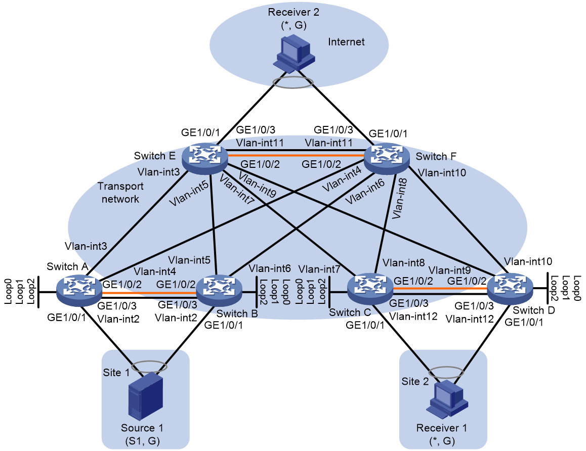
|
Device |
Interface |
IP address |
Device |
Interface |
IP address |
|
Switch A |
Loop0 |
1.1.1.1/32 |
Switch B |
Loop0 |
2.2.2.2/32 |
|
|
Loop1 |
1.2.3.4/32 |
|
Loop1 |
1.2.3.4/32 |
|
|
Loop2 |
1.2.3.4/32 |
|
Loop2 |
1.2.3.4/32 |
|
|
Vlan-int2 |
192.168.1.1/24 |
|
Vlan-int2 |
192.168.1.2/24 |
|
|
Vlan-int3 |
30.1.1.1/24 |
|
Vlan-int5 |
50.1.1.2/24 |
|
|
Vlan-int4 |
40.1.1.1/24 |
|
Vlan-int6 |
60.1.1.2/24 |
|
|
Vlan-int100 |
100.1.1.1/24 |
|
Vlan-int100 |
100.1.1.2/24 |
|
Switch C |
Loop0 |
3.3.3.3/32 |
Switch D |
Loop0 |
4.4.4.4/32 |
|
|
Loop1 |
1.2.3.6/32 |
|
Loop1 |
1.2.3.6/32 |
|
|
Loop2 |
1.2.3.6/32 |
|
Loop2 |
1.2.3.6/32 |
|
|
Vlan-int7 |
70.1.1.3/24 |
|
Vlan-int9 |
90.1.1.4/24 |
|
|
Vlan-int8 |
80.1.1.3/24 |
|
Vlan-int10 |
100.1.1.4/24 |
|
|
Vlan-int12 |
192.168.3.1/24 |
|
Vlan-int12 |
192.168.3.2/24 |
|
|
Vlan-int100 |
100.1.1.3/24 |
|
Vlan-int100 |
100.1.1.4/24 |
|
Switch E |
Loop0 |
5.5.5.5/32 |
Switch F |
Loop0 |
6.6.6.6/32 |
|
|
Loop1 |
1.2.3.5/32 |
|
Loop1 |
1.2.3.5/32 |
|
|
Loop2 |
1.2.3.5/32 |
|
Loop2 |
1.2.3.5/32 |
|
|
Vlan-int3 |
30.1.1.5/24 |
|
Vlan-int4 |
40.1.1.6/24 |
|
|
Vlan-int5 |
50.1.1.5/24 |
|
Vlan-int6 |
60.1.1.6/24 |
|
|
Vlan-int7 |
70.1.1.5/24 |
|
Vlan-int8 |
80.1.1.6/24 |
|
|
Vlan-int9 |
90.1.1.5/24 |
|
Vlan-int10 |
100.1.1.6/24 |
|
|
Vlan-int11 |
192.168.4.1/24 |
|
Vlan-int11 |
192.168.4.2/24 |
|
|
Vlan-int100 |
100.1.1.5/24 |
|
Vlan-int100 |
100.1.1.6/24 |
Procedure
1. Configure IP addresses and unicast routing settings:
# Assign IP addresses to interfaces, as shown in Figure 14. (Details not shown.)
# Configure OSPF on all transport network switches (Switches A through F) for them to reach one another. (Details not shown.)
2. Configure Switch A:
# Enable L2VPN.
<SwitchA> system-view
[SwitchA] l2vpn enable
# Specify the virtual VTEP address as 1.2.3.4.
[SwitchA] evpn m-lag group 1.2.3.4
# Specify the IP addresses of the member devices in the M-LAG system.
[SwitchA] evpn m-lag local 1.1.1.1 remote 2.2.2.2
# Enable IP multicast routing.
[SwitchA] multicast routing
[SwitchA-mrib] quit
# Enable the IGMP snooping feature.
[SwitchA] igmp-snooping
[SwitchA-igmp-snooping] quit
# Disable remote MAC address learning and remote ARP learning.
[SwitchA] vxlan tunnel mac-learning disable
[SwitchA] vxlan tunnel arp-learning disable
# Create an EVPN instance on VSI vpna.
[SwitchA] vsi vpna
[SwitchA-vsi-vpna] evpn encapsulation vxlan
[SwitchA-vsi-vpna-evpn-vxlan] route-distinguisher auto
[SwitchA-vsi-vpna-evpn-vxlan] vpn-target auto
[SwitchA-vsi-vpna-evpn-vxlan] quit
# Enable IGMP snooping and IGMP snooping proxying on VSI vpna.
[SwitchA-vsi-vpna] igmp-snooping enable
[SwitchA-vsi-vpna] igmp-snooping proxy enable
# Create VXLAN 10.
[SwitchA-vsi-vpna] vxlan 10
[SwitchA-vsi-vpna-vxlan-10] quit
[SwitchA-vsi-vpna] quit
# Configure BGP to advertise BGP EVPN routes.
[SwitchA] bgp 200
[SwitchA-bgp-default] peer 5.5.5.5 as-number 200
[SwitchA-bgp-default] peer 5.5.5.5 connect-interface loopback 0
[SwitchA-bgp-default] peer 6.6.6.6 as-number 200
[SwitchA-bgp-default] peer 6.6.6.6 connect-interface loopback 0
[SwitchA-bgp-default] address-family l2vpn evpn
[SwitchA-bgp-default-evpn] peer 5.5.5.5 enable
[SwitchA-bgp-default-evpn] peer 6.6.6.6 enable
[SwitchA-bgp-default-evpn] quit
[SwitchA-bgp-default] quit
# Configure RD and route target settings for VPN instance vpna.
[SwitchA] ip vpn-instance vpna
[SwitchA-vpn-instance-vpna] route-distinguisher 1:1
[SwitchA-vpn-instance-vpna] address-family ipv4
[SwitchA-vpn-ipv4-vpna] vpn-target 2:2
[SwitchA-vpn-ipv4-vpna] quit
[SwitchA-vpn-instance-vpna] address-family evpn
[SwitchA-vpn-evpn-vpna] vpn-target 1:1
[SwitchA-vpn-evpn-vpna] quit
[SwitchA-vpn-instance-vpna] quit
# Configure VSI-interface 1.
[SwitchA] interface vsi-interface 1
[SwitchA-Vsi-interface1] ip binding vpn-instance vpna
[SwitchA-Vsi-interface1] ip address 10.1.1.1 255.255.255.0
[SwitchA-Vsi-interface1] pim sm
[SwitchA-Vsi-interface1] igmp enable
[SwitchA-Vsi-interface1] pim distributed-dr
[SwitchA-Vsi-interface1] mac-address 1-1-1
[SwitchA-Vsi-interface1] distributed-gateway local
[SwitchA-Vsi-interface1] local-proxy-arp enable
[SwitchA-Vsi-interface1] quit
# Associate VSI-interface 3 with VPN instance vpna, and configure the L3 VXLAN ID as 1000 for the VPN instance.
[SwitchA] interface vsi-interface 3
[SwitchA-Vsi-interface3] ip binding vpn-instance vpna
[SwitchA-Vsi-interface3] l3-vni 1000
[SwitchA-Vsi-interface3] pim sm
[SwitchA-Vsi-interface3] quit
# Enable IP multicast routing for VPN instance vpna.
[SwitchA] multicast routing vpn-instance vpna
[SwitchA-mrib-vpna] quit
# Configure Loopback 0.
[SwitchA] interface loopback 0
[SwitchA-LoopBack0] ip address 1.1.1.1 32
[SwitchA-LoopBack0] pim sm
[SwitchA-LoopBack0] ospf 1 area 0
[SwitchA-LoopBack0] quit
# Configure Loopback 1.
[SwitchA] interface loopback 1
[SwitchA-LoopBack1] ip address 1.2.3.4 32
[SwitchA-LoopBack1] pim sm
[SwitchA-LoopBack1] ospf 1 area 0
[SwitchA-LoopBack1] quit
# Configure Loopback 2.
[SwitchA] interface loopback 2
[SwitchA-LoopBack2] ip binding vpn-instance vpna
[SwitchA-LoopBack2] ip address 1.2.3.4 32
[SwitchA-LoopBack2] pim sm
[SwitchA-LoopBack2] quit
# Create an MDT-based MVXLAN for VPN instance vpna and enter MVXLAN IPv4 address family view. Configure the default group, MVXLAN source interface, and data group range settings.
[SwitchA] multicast-vpn vxlan vpn-instance vpna mode mdt
[SwitchA-mvxlan-vpna] address-family ipv4
[SwitchA-mvxlan-vpna-ipv4] default-group 236.0.0.1
[SwitchA-mvxlan-vpna-ipv4] source loopback 1 evpn-mlag-group
[SwitchA-mvxlan-vpna-ipv4] data-group 239.0.0.1 30
[SwitchA-mvxlan-vpna-ipv4] quit
[SwitchA-mvxlan-vpna] quit
# Enter VPN instance PIM view, and configure Loopback 2 as a candidate-BSR and candidate-RP in VPN instance vpna.
[SwitchA] pim vpn-instance vpna
[SwitchA-pim-vpna] c-bsr 1.2.3.4
[SwitchA-pim-vpna] c-rp 1.2.3.4
[SwitchA-pim-vpna] quit
# Specify VSI-interface 1 as the gateway interface for VSI vpna.
[SwitchA] vsi vpna
[SwitchA-vsi-vpna] gateway vsi-interface 1
[SwitchA-vsi-vpna] quit
# Configure VLAN 100 as the reserved VLAN for the peer link.
[SwitchA] vlan 100
[SwitchA–vlan100] m-lag peer-link reserved
[SwitchA–vlan100] quit
# Configure an M-LAG interface.
[SwitchA] interface bridge-aggregation 21
[SwitchA-Bridge-Aggregation21] port link-type trunk
[SwitchA-Bridge-Aggregation21] port trunk permit vlan 1 20 to 29
[SwitchA-Bridge-Aggregation21] link-aggregation mode dynamic
[SwitchA-Bridge-Aggregation21] port m-lag group 1
# Map Ethernet service instance 100 to VSI vpna.
[SwitchA-Bridge-Aggregation21] service-instance 100
[SwitchA-Bridge-Aggregation21-srv100] encapsulation s-vid 21
[SwitchA-Bridge-Aggregation21-srv100] xconnect vsi vpna
[SwitchA-Bridge-Aggregation21-srv100] quit
# Assign a Layer 2 Ethernet interface to the aggregation group of the M-LAG interface.
[SwitchA] interface gigabitethernet 1/0/1
[SwitchA-GigabitEthernet1/0/1] port link-aggregation group 21
[SwitchA-GigabitEthernet1/0/1] quit
# Configure an aggregate interface as the peer-link interface.
[SwitchA] interface bridge-aggregation 9
[SwitchA-Bridge-Aggregation9] port link-type trunk
[SwitchA-Bridge-Aggregation9] port trunk permit vlan all
[SwitchA-Bridge-Aggregation9] link-aggregation mode dynamic
[SwitchA-Bridge-Aggregation9] port m-lag peer-link 1
[SwitchA-Bridge-Aggregation9] quit
# Assign a Layer 2 Ethernet interface to the aggregation group of the peer-link interface.
[SwitchA] interface gigabitethernet 1/0/2
[SwitchA-GigabitEthernet1/0/2] port link-aggregation group 9
[SwitchA-GigabitEthernet1/0/2] quit
# Exclude the interface used for setting up the keepalive link from the shutdown action by M-LAG MAD.
[SwitchA] m-lag mad exclude interface gigabitethernet 1/0/3
# Configure M-LAG system parameters.
[SwitchA] m-lag restore-delay 180
[SwitchA] m-lag system-mac 1-1-1
[SwitchA] m-lag system-number 1
[SwitchA] m-lag system-priority 10
[SwitchA] m-lag keepalive ip destination 192.168.1.2 source 192.168.1.1
3. Configure Switch B:
# Enable L2VPN.
<SwitchB> system-view
[SwitchB] l2vpn enable
# Specify the virtual VTEP address as 1.2.3.4.
[SwitchB] evpn m-lag group 1.2.3.4
# Specify the IP addresses of the member devices in the M-LAG system.
[SwitchB] evpn m-lag local 2.2.2.2 remote 1.1.1.1
# Enable IP multicast routing.
[SwitchB] multicast routing
[SwitchB-mrib] quit
# Enable the IGMP snooping feature.
[SwitchB] igmp-snooping
[SwitchB-igmp-snooping] quit
# Disable remote MAC address learning and remote ARP learning.
[SwitchB] vxlan tunnel mac-learning disable
[SwitchB] vxlan tunnel arp-learning disable
# Create an EVPN instance on VSI vpna.
[SwitchB] vsi vpna
[SwitchB-vsi-vpna] evpn encapsulation vxlan
[SwitchB-vsi-vpna-evpn-vxlan] route-distinguisher auto
[SwitchB-vsi-vpna-evpn-vxlan] vpn-target auto
[SwitchB-vsi-vpna-evpn-vxlan] quit
# Enable IGMP snooping and IGMP snooping proxying on VSI vpna.
[SwitchB-vsi-vpna] igmp-snooping enable
[SwitchB-vsi-vpna] igmp-snooping proxy enable
# Create VXLAN 10.
[SwitchB-vsi-vpna] vxlan 10
[SwitchB-vsi-vpna-vxlan-10] quit
[SwitchB-vsi-vpna] quit
# Configure BGP to advertise BGP EVPN routes.
[SwitchB] bgp 200
[SwitchB-bgp-default] peer 5.5.5.5 as-number 200
[SwitchB-bgp-default] peer 5.5.5.5 connect-interface loopback 0
[SwitchB-bgp-default] peer 6.6.6.6 as-number 200
[SwitchB-bgp-default] peer 6.6.6.6 connect-interface loopback 0
[SwitchB-bgp-default] address-family l2vpn evpn
[SwitchB-bgp-default-evpn] peer 5.5.5.5 enable
[SwitchB-bgp-default-evpn] peer 6.6.6.6 enable
[SwitchB-bgp-default-evpn] quit
[SwitchB-bgp-default] quit
# Configure RD and route target settings for VPN instance vpna.
[SwitchB] ip vpn-instance vpna
[SwitchB-vpn-instance-vpna] route-distinguisher 1:1
[SwitchB-vpn-instance-vpna] address-family ipv4
[SwitchB-vpn-ipv4-vpna] vpn-target 2:2
[SwitchB-vpn-ipv4-vpna] quit
[SwitchB-vpn-instance-vpna] address-family evpn
[SwitchB-vpn-evpn-vpna] vpn-target 1:1
[SwitchB-vpn-evpn-vpna] quit
[SwitchB-vpn-instance-vpna] quit
# Configure VSI-interface 1.
[SwitchB] interface vsi-interface 1
[SwitchB-Vsi-interface1] ip binding vpn-instance vpna
[SwitchB-Vsi-interface1] ip address 10.1.1.1 255.255.255.0
[SwitchB-Vsi-interface1] pim sm
[SwitchB-Vsi-interface1] igmp enable
[SwitchB-Vsi-interface1] pim distributed-dr
[SwitchB-Vsi-interface1] mac-address 1-1-1
[SwitchB-Vsi-interface1] distributed-gateway local
[SwitchB-Vsi-interface1] local-proxy-arp enable
[SwitchB-Vsi-interface1] quit
# Associate VSI-interface 3 with VPN instance vpna, and configure the L3 VXLAN ID as 1000 for the VPN instance.
[SwitchB] interface vsi-interface 3
[SwitchB-Vsi-interface3] ip binding vpn-instance vpna
[SwitchB-Vsi-interface3] l3-vni 1000
[SwitchB-Vsi-interface3] pim sm
[SwitchB-Vsi-interface3] quit
# Enable IP multicast routing for VPN instance vpna.
[SwitchB] multicast routing vpn-instance vpna
[SwitchB-mrib-vpna] quit
# Configure Loopback 0.
[SwitchB] interface loopback 0
[SwitchB-LoopBack0] ip address 2.2.2.2 32
[SwitchB-LoopBack0] pim sm
[SwitchB-LoopBack0] ospf 1 area 0
[SwitchB-LoopBack0] quit
# Configure Loopback 1.
[SwitchB] interface loopback 1
[SwitchB-LoopBack1] ip address 1.2.3.4 32
[SwitchB-LoopBack1] pim sm
[SwitchB-LoopBack1] ospf 1 area 0
[SwitchB-LoopBack1] quit
# Configure Loopback 2.
[SwitchB] interface loopback 2
[SwitchB-LoopBack2] ip binding vpn-instance vpna
[SwitchB-LoopBack2] ip address 1.2.3.4 32
[SwitchB-LoopBack2] pim sm
[SwitchB-LoopBack2] quit
# Create an MDT-based MVXLAN for VPN instance vpna and enter MVXLAN IPv4 address family view. Configure the default group, MVXLAN source interface, and data group range settings.
[SwitchB] multicast-vpn vxlan vpn-instance vpna mode mdt
[SwitchB-mvxlan-vpna] address-family ipv4
[SwitchB-mvxlan-vpna-ipv4] default-group 236.0.0.1
[SwitchB-mvxlan-vpna-ipv4] source loopback 1 evpn-mlag-group
[SwitchB-mvxlan-vpna-ipv4] data-group 239.0.0.1 30
[SwitchB-mvxlan-vpna-ipv4] quit
[SwitchB-mvxlan-vpna] quit
# Enter VPN instance PIM view, and configure Loopback 2 as a candidate-BSR and candidate-RP in VPN instance vpna.
[SwitchB] pim vpn-instance vpna
[SwitchB-pim-vpna] c-bsr 1.2.3.4
[SwitchB-pim-vpna] c-rp 1.2.3.4
[SwitchB-pim-vpna] quit
# Specify VSI-interface 1 as the gateway interface for VSI vpna.
[SwitchB] vsi vpna
[SwitchB-vsi-vpna] gateway vsi-interface 1
[SwitchB-vsi-vpna] quit
# Configure VLAN 100 as the reserved VLAN for the peer link.
[SwitchB] vlan 100
[SwitchB–vlan100] m-lag peer-link reserved
[SwitchB–vlan100] quit
# Configure an M-LAG interface.
[SwitchB] interface bridge-aggregation 21
[SwitchB-Bridge-Aggregation21] port link-type trunk
[SwitchB-Bridge-Aggregation21] port trunk permit vlan 1 20 to 29
[SwitchB-Bridge-Aggregation21] link-aggregation mode dynamic
[SwitchB-Bridge-Aggregation21] port m-lag group 1
# Map Ethernet service instance 100 to VSI vpna.
[SwitchB-Bridge-Aggregation21] service-instance 100
[SwitchB-Bridge-Aggregation21-srv100] encapsulation s-vid 21
[SwitchB-Bridge-Aggregation21-srv100] xconnect vsi vpna
[SwitchB-Bridge-Aggregation21-srv100] quit
# Assign a Layer 2 Ethernet interface to the aggregation group of the M-LAG interface.
[SwitchB] interface gigabitethernet 1/0/1
[SwitchB-GigabitEthernet1/0/1] port link-aggregation group 21
[SwitchB-GigabitEthernet1/0/1] quit
# Configure an aggregate interface as the peer-link interface.
[SwitchB] interface bridge-aggregation 9
[SwitchB-Bridge-Aggregation9] port link-type trunk
[SwitchB-Bridge-Aggregation9] port trunk permit vlan all
[SwitchB-Bridge-Aggregation9] link-aggregation mode dynamic
[SwitchB-Bridge-Aggregation9] port m-lag peer-link 1
[SwitchB-Bridge-Aggregation9] quit
# Assign a Layer 2 Ethernet interface to the aggregation group of the peer-link interface.
[SwitchB] interface gigabitethernet 1/0/2
[SwitchB-GigabitEthernet1/0/2] port link-aggregation group 9
[SwitchB-GigabitEthernet1/0/2] quit
# Exclude the interface used for setting up the keepalive link from the shutdown action by M-LAG MAD.
[SwitchB] m-lag mad exclude interface gigabitethernet 1/0/3
# Configure M-LAG system parameters.
[SwitchB] m-lag restore-delay 180
[SwitchB] m-lag system-mac 1-1-1
[SwitchB] m-lag system-number 2
[SwitchB] m-lag system-priority 10
[SwitchB] m-lag keepalive ip destination 192.168.1.1 source 192.168.1.2
4. Configure Switch C:
# Enable L2VPN.
<SwitchC> system-view
[SwitchC] l2vpn enable
# Specify the virtual VTEP address as 1.2.3.6.
[SwitchC] evpn m-lag group 1.2.3.6
# Specify the IP addresses of the member devices in the M-LAG system.
[SwitchC] evpn m-lag local 3.3.3.3 remote 4.4.4.4
# Enable IP multicast routing.
[SwitchC] multicast routing
[SwitchC-mrib] quit
# Enable the IGMP snooping feature.
[SwitchC] igmp-snooping
[SwitchC-igmp-snooping] quit
# Disable remote MAC address learning and remote ARP learning.
[SwitchC] vxlan tunnel mac-learning disable
[SwitchC] vxlan tunnel arp-learning disable
# Create an EVPN instance on VSI vpna.
[SwitchC] vsi vpna
[SwitchC-vsi-vpna] evpn encapsulation vxlan
[SwitchC-vsi-vpna-evpn-vxlan] route-distinguisher auto
[SwitchC-vsi-vpna-evpn-vxlan] vpn-target auto
[SwitchC-vsi-vpna-evpn-vxlan] quit
# Enable IGMP snooping and IGMP snooping proxying on VSI vpna.
[SwitchC-vsi-vpna] igmp-snooping enable
[SwitchC-vsi-vpna] igmp-snooping proxy enable
# Create VXLAN 10.
[SwitchC-vsi-vpna] vxlan 10
[SwitchC-vsi-vpna-vxlan-10] quit
[SwitchC-vsi-vpna] quit
# Configure BGP to advertise BGP EVPN routes.
[SwitchC] bgp 200
[SwitchC-bgp-default] peer 6.6.6.6 as-number 200
[SwitchC-bgp-default] peer 6.6.6.6 connect-interface loopback 0
[SwitchC-bgp-default] peer 5.5.5.5 as-number 200
[SwitchC-bgp-default] peer 5.5.5.5 connect-interface loopback 0
[SwitchC-bgp-default] address-family l2vpn evpn
[SwitchC-bgp-default-evpn] peer 6.6.6.6 enable
[SwitchC-bgp-default-evpn] peer 5.5.5.5 enable
[SwitchC-bgp-default-evpn] quit
[SwitchC-bgp-default] quit
# Configure RD and route target settings for VPN instance vpna.
[SwitchC] ip vpn-instance vpna
[SwitchC-vpn-instance-vpna] route-distinguisher 1:1
[SwitchC-vpn-instance-vpna] address-family ipv4
[SwitchC-vpn-ipv4-vpna] vpn-target 2:2
[SwitchC-vpn-ipv4-vpna] quit
[SwitchC-vpn-instance-vpna] address-family evpn
[SwitchC-vpn-evpn-vpna] vpn-target 1:1
[SwitchC-vpn-evpn-vpna] quit
[SwitchC-vpn-instance-vpna] quit
# Configure VSI-interface 1.
[SwitchC] interface vsi-interface 1
[SwitchC-Vsi-interface1] ip binding vpn-instance vpna
[SwitchC-Vsi-interface1] ip address 10.1.1.1 255.255.255.0
[SwitchC-Vsi-interface1] pim sm
[SwitchC-Vsi-interface1] igmp enable
[SwitchC-Vsi-interface1] pim distributed-dr
[SwitchC-Vsi-interface1] mac-address 1-1-1
[SwitchC-Vsi-interface1] distributed-gateway local
[SwitchC-Vsi-interface1] local-proxy-arp enable
[SwitchC-Vsi-interface1] quit
# Associate VSI-interface 3 with VPN instance vpna, and configure the L3 VXLAN ID as 1000 for the VPN instance.
[SwitchC] interface vsi-interface 3
[SwitchC-Vsi-interface3] ip binding vpn-instance vpna
[SwitchC-Vsi-interface3] l3-vni 1000
[SwitchC-Vsi-interface3] pim sm
[SwitchC-Vsi-interface3] quit
# Enable IP multicast routing for VPN instance vpna.
[SwitchC] multicast routing vpn-instance vpna
[SwitchC-mrib-vpna] quit
# Configure Loopback 0.
[SwitchC] interface loopback 0
[SwitchC-LoopBack0] ip address 3.3.3.3 32
[SwitchC-LoopBack0] pim sm
[SwitchC-LoopBack0] ospf 1 area 0
[SwitchC-LoopBack1] quit
# Configure Loopback 1.
[SwitchC] interface loopback 1
[SwitchC-LoopBack1] ip address 1.2.3.6 32
[SwitchC-LoopBack1] pim sm
[SwitchC-LoopBack1] ospf 1 area 0
[SwitchC-LoopBack1] quit
# Configure Loopback 2.
[SwitchB] interface loopback 2
[SwitchC-LoopBack2] ip binding vpn-instance vpna
[SwitchC-LoopBack2] ip address 1.2.3.6 255.255.255.255
[SwitchC-LoopBack2] pim sm
[SwitchC-LoopBack2] quit
# Create an MDT-based MVXLAN for VPN instance vpna and enter MVXLAN IPv4 address family view. Configure the default group, MVXLAN source interface, and data group range settings.
[SwitchC] multicast-vpn vxlan vpn-instance vpna mode mdt
[SwitchC-mvxlan-vpna] address-family ipv4
[SwitchC-mvxlan-vpna-ipv4] default-group 236.0.0.1
[SwitchC-mvxlan-vpna-ipv4] source loopback 1 evpn-mlag-group
[SwitchC-mvxlan-vpna-ipv4] data-group 239.0.1.0 30
[SwitchC-mvxlan-vpna-ipv4] m-lag local 3.3.3.3 remote 4.4.4.4
[SwitchC-mvxlan-vpna-ipv4] quit
[SwitchC-mvxlan-vpna] quit
# Enter VPN instance PIM view, and configure Loopback 2 as a candidate-BSR and candidate-RP in VPN instance vpna.
[SwitchC] pim vpn-instance vpna
[SwitchC-pim-vpna] c-bsr 1.2.3.6
[SwitchC-pim-vpna] c-rp 1.2.3.6
[SwitchC-pim-vpna] quit
# Specify VSI-interface 1 as the gateway interface for VSI vpna.
[SwitchC] vsi vpna
[SwitchC-vsi-vpna] gateway vsi-interface 1
[SwitchC-vsi-vpna] quit
# Configure VLAN 100 as the reserved VLAN for the peer link.
[SwitchC] vlan 100
[SwitchC–vlan100] m-lag peer-link reserved
[SwitchC–vlan100] quit
# Configure an M-LAG interface.
[SwitchC] interface bridge-aggregation 17
[SwitchC-Bridge-Aggregation17] link-aggregation mode dynamic
[SwitchC-Bridge-Aggregation17] port m-lag group 17
# Map Ethernet service instance 20 to VSI vpna.
[SwitchC-Bridge-Aggregation17] service-instance 20
[SwitchC-Bridge-Aggregation17-srv20] encapsulation s-vid 2
[SwitchC-Bridge-Aggregation17-srv20] xconnect vsi vpna
[SwitchC-Bridge-Aggregation17-srv20] quit
# Assign a Layer 2 Ethernet interface to the aggregation group of the M-LAG interface.
[SwitchC]interface gigabitethernet 1/0/1
[SwitchC-GigabitEthernet1/0/1] port link-aggregation group 17
[SwitchC-GigabitEthernet1/0/1] quit
# Configure an aggregate interface as the peer-link interface.
[SwitchC] interface bridge-aggregation 9
[SwitchC-Bridge-Aggregation9] link-aggregation mode dynamic
[SwitchC-Bridge-Aggregation9] port m-lag peer-link 1
[SwitchC-Bridge-Aggregation9] quit
# Assign a Layer 2 Ethernet interface to the aggregation group of the peer-link interface.
[SwitchC] interface gigabitethernet 1/0/2
[SwitchC-GigabitEthernet1/0/2] port link-aggregation group 9
# Exclude the interface used for setting up the keepalive link from the shutdown action by M-LAG MAD.
[SwitchC] m-lag mad exclude interface gigabitethernet 1/0/3
# Configure M-LAG system parameters.
[SwitchC] m-lag restore-delay 180
[SwitchC] m-lag system-mac 2-2-2
[SwitchC] m-lag system-number 1
[SwitchC] m-lag system-priority 10
[SwitchC] m-lag keepalive ip destination 192.168.3.2 source 192.168.3.1
# Configure Bridge-Aggregation 17 as a trunk port and configure it to permit VLANs 20 through 29.
[SwitchC] interface bridge-aggregation 17
[SwitchC-Bridge-Aggregation17] port link-type trunk
[SwitchC-Bridge-Aggregation17] undo port trunk permit vlan 1
[SwitchC-Bridge-Aggregation17] port trunk permit vlan 20 to 29
[SwitchC-Bridge-Aggregation17] quit
# Configure the peer-link interface as a trunk port and configure it to permit all VLANs.
[SwitchC] interface bridge-aggregation 9
[SwitchC-Bridge-Aggregation9] port link-type trunk
[SwitchC-Bridge-Aggregation9] undo port trunk permit vlan 1
[SwitchC-Bridge-Aggregation9] port trunk permit vlan all
[SwitchC-Bridge-Aggregation9] quit
5. Configure Switch D:
# Enable L2VPN.
<SwitchD> system-view
[SwitchD] l2vpn enable
# Specify the virtual VTEP address as 1.2.3.6.
[SwitchD] evpn m-lag group 1.2.3.6
# Specify the IP addresses of the member devices in the M-LAG system.
[SwitchD] evpn m-lag local 4.4.4.4 remote 3.3.3.3
# Enable IP multicast routing.
[SwitchD] multicast routing
[SwitchD-mrib] quit
# Enable the IGMP snooping feature.
[SwitchD] igmp-snooping
[SwitchD-igmp-snooping] quit
# Disable remote MAC address learning and remote ARP learning.
[SwitchD] vxlan tunnel mac-learning disable
[SwitchD] vxlan tunnel arp-learning disable
# Create an EVPN instance on VSI vpna.
[SwitchD] vsi vpna
[SwitchD-vsi-vpna] evpn encapsulation vxlan
[SwitchD-vsi-vpna-evpn-vxlan] route-distinguisher auto
[SwitchD-vsi-vpna-evpn-vxlan] vpn-target auto
[SwitchD-vsi-vpna-evpn-vxlan] quit
# Enable IGMP snooping and IGMP snooping proxying on VSI vpna.
[SwitchD-vsi-vpna] igmp-snooping enable
[SwitchD-vsi-vpna] igmp-snooping proxy enable
# Create VXLAN 10.
[SwitchD-vsi-vpna] vxlan 10
[SwitchD-vsi-vpna-vxlan-10] quit
[SwitchD-vsi-vpna] quit
# Configure BGP to advertise BGP EVPN routes.
[SwitchD] bgp 200
[SwitchD-bgp-default] peer 6.6.6.6 as-number 200
[SwitchD-bgp-default] peer 6.6.6.6 connect-interface loopback 0
[SwitchD-bgp-default] peer 5.5.5.5 as-number 200
[SwitchD-bgp-default] peer 5.5.5.5 connect-interface loopback 0
[SwitchD-bgp-default] address-family l2vpn evpn
[SwitchD-bgp-default-evpn] peer 6.6.6.6 enable
[SwitchD-bgp-default-evpn] peer 5.5.5.5 enable
[SwitchD-bgp-default-evpn] quit
[SwitchD-bgp-default] quit
# Configure RD and route target settings for VPN instance vpna.
[SwitchD] ip vpn-instance vpna
[SwitchD-vpn-instance-vpna] route-distinguisher 1:1
[SwitchD-vpn-instance-vpna] address-family ipv4
[SwitchD-vpn-ipv4-vpna] vpn-target 2:2
[SwitchD-vpn-ipv4-vpna] quit
[SwitchD-vpn-instance-vpna] address-family evpn
[SwitchD-vpn-evpn-vpna] vpn-target 1:1
[SwitchD-vpn-evpn-vpna] quit
[SwitchD-vpn-instance-vpna] quit
# Configure VSI-interface 1.
[SwitchD] interface vsi-interface 1
[SwitchD-Vsi-interface1] ip binding vpn-instance vpna
[SwitchD-Vsi-interface1] ip address 10.1.1.1 255.255.255.0
[SwitchD-Vsi-interface1] pim sm
[SwitchD-Vsi-interface1] igmp enable
[SwitchD-Vsi-interface1] pim distributed-dr
[SwitchD-Vsi-interface1] mac-address 1-1-1
[SwitchD-Vsi-interface1] distributed-gateway local
[SwitchD-Vsi-interface1] local-proxy-arp enable
[SwitchD-Vsi-interface1] quit
# Associate VSI-interface 3 with VPN instance vpna, and configure the L3 VXLAN ID as 1000 for the VPN instance.
[SwitchD] interface vsi-interface 3
[SwitchD-Vsi-interface3] ip binding vpn-instance vpna
[SwitchD-Vsi-interface3] l3-vni 1000
[SwitchD-Vsi-interface3] pim sm
[SwitchD-Vsi-interface3] quit
# Enable IP multicast routing for VPN instance vpna.
[SwitchD] multicast routing vpn-instance vpna
[SwitchD-mrib-vpna] quit
# Configure Loopback 0.
[SwitchD] interface loopback 0
[SwitchD-LoopBack0] ip address 4.4.4.4 32
[SwitchD-LoopBack0] pim sm
[SwitchD-LoopBack0] ospf 1 area 0
[SwitchD-LoopBack1] quit
# Configure Loopback 1.
[SwitchD] interface loopback 1
[SwitchD-LoopBack1] ip address 1.2.3.6 32
[SwitchD-LoopBack1] pim sm
[SwitchD-LoopBack1] ospf 1 area 0
[SwitchD-LoopBack1] quit
# Configure Loopback 2.
[SwitchD] interface loopback 2
[SwitchD-LoopBack2] ip binding vpn-instance vpna
[SwitchD-LoopBack2] ip address 1.2.3.6 255.255.255.255
[SwitchD-LoopBack2] pim sm
[SwitchD-LoopBack2] quit
# Create an MDT-based MVXLAN for VPN instance vpna and enter MVXLAN IPv4 address family view. Configure the default group, MVXLAN source interface, and data group range settings.
[SwitchD] multicast-vpn vxlan vpn-instance vpna mode mdt
[SwitchD-mvxlan-vpna] address-family ipv4
[SwitchD-mvxlan-vpna-ipv4] default-group 236.0.0.1
[SwitchD-mvxlan-vpna-ipv4] source loopback 1 evpn-mlag-group
[SwitchD-mvxlan-vpna-ipv4] data-group 239.0.1.0 30
[SwitchD-mvxlan-vpna-ipv4] m-lag local 4.4.4.4 remote 3.3.3.3
[SwitchD-mvxlan-vpna-ipv4] quit
[SwitchD-mvxlan-vpna] quit
# Enter VPN instance PIM view, and configure Loopback 2 as a candidate-BSR and candidate-RP in VPN instance vpna.
[SwitchD] pim vpn-instance vpna
[SwitchD-pim-vpna] c-bsr 1.2.3.6
[SwitchD-pim-vpna] c-rp 1.2.3.6
[SwitchD-pim-vpna] quit
# Specify VSI-interface 1 as the gateway interface for VSI vpna.
[SwitchD] vsi vpna
[SwitchD-vsi-vpna] gateway vsi-interface 1
[SwitchD-vsi-vpna] quit
# Configure VLAN 100 as the reserved VLAN for the peer link.
[SwitchD] vlan 100
[SwitchD–vlan100] m-lag peer-link reserved
[SwitchD–vlan100] quit
# Configure an M-LAG interface.
[SwitchD] interface bridge-aggregation 17
[SwitchD-Bridge-Aggregation17] link-aggregation mode dynamic
[SwitchD-Bridge-Aggregation17] port m-lag group 17
# Map Ethernet service instance 20 to VSI vpna.
[SwitchD-Bridge-Aggregation17] service-instance 20
[SwitchD-Bridge-Aggregation17-srv20] encapsulation s-vid 2
[SwitchD-Bridge-Aggregation17-srv20] xconnect vsi vpna
[SwitchD-Bridge-Aggregation17-srv20] quit
# Assign a Layer 2 Ethernet interface to the aggregation group of the M-LAG interface.
[SwitchD] interface gigabitethernet 1/0/1
[SwitchD-GigabitEthernet1/0/1] port link-aggregation group 17
[SwitchD-GigabitEthernet1/0/1] quit
# Configure an aggregate interface as the peer-link interface.
[SwitchD] interface bridge-aggregation 9
[SwitchD-Bridge-Aggregation9] link-aggregation mode dynamic
[SwitchD-Bridge-Aggregation9] port m-lag peer-link 1
[SwitchD-Bridge-Aggregation9] quit
# Assign a Layer 2 Ethernet interface to the aggregation group of the peer-link interface.
[SwitchD] interface gigabitethernet 1/0/2
[SwitchD-GigabitEthernet1/0/2] port link-aggregation group 9
# Exclude the interface used for setting up the keepalive link from the shutdown action by M-LAG MAD.
[SwitchD] m-lag mad exclude interface gigabitethernet 1/0/3
# Configure M-LAG system parameters.
[SwitchD] m-lag restore-delay 180
[SwitchD] m-lag system-mac 2-2-2
[SwitchD] m-lag system-number 2
[SwitchD] m-lag system-priority 10
[SwitchD] m-lag keepalive ip destination 192.168.3.1 source 192.168.3.2
# Configure Bridge-Aggregation 17 as a trunk port and configure it to permit VLANs 20 through 29.
[SwitchD] interface bridge-aggregation 17
[SwitchD-Bridge-Aggregation17] port link-type trunk
[SwitchD-Bridge-Aggregation17] undo port trunk permit vlan 1
[SwitchD-Bridge-Aggregation17] port trunk permit vlan 20 to 29
[SwitchD-Bridge-Aggregation17] quit
# Configure the peer-link interface as a trunk port and configure it to permit all VLANs.
[SwitchD] interface bridge-aggregation 9
[SwitchD-Bridge-Aggregation9] port link-type trunk
[SwitchD-Bridge-Aggregation9] undo port trunk permit vlan 1
[SwitchD-Bridge-Aggregation9] port trunk permit vlan all
[SwitchD-Bridge-Aggregation9] quit
6. Configure Switch E:
# Enable L2VPN.
<SwitchE> system-view
[SwitchE] l2vpn enable
# Specify the virtual VTEP address as 1.2.3.5.
[SwitchE] evpn m-lag group 1.2.3.5
# Specify the IP addresses of the member devices in the M-LAG system.
[SwitchE] evpn m-lag local 5.5.5.5 remote 6.6.6.6
# Enable IP multicast routing.
[SwitchE] multicast routing
[SwitchE-mrib] quit
# Enable the IGMP snooping feature.
[SwitchE] igmp-snooping
[SwitchE-igmp-snooping] quit
# Disable remote MAC address learning and remote ARP learning.
[SwitchE] vxlan tunnel mac-learning disable
[SwitchE] vxlan tunnel arp-learning disable
# Create an EVPN instance on VSI vpna.
[SwitchE] vsi vpna
[SwitchE-vsi-vpna] evpn encapsulation vxlan
[SwitchE-vsi-vpna-evpn-vxlan] route-distinguisher auto
[SwitchE-vsi-vpna-evpn-vxlan] vpn-target auto
[SwitchE-vsi-vpna-evpn-vxlan] quit
# Enable IGMP snooping and IGMP snooping proxying on VSI vpna.
[SwitchE-vsi-vpna] igmp-snooping enable
[SwitchE-vsi-vpna] igmp-snooping proxy enable
# Create VXLAN 10.
[SwitchE-vsi-vpna] vxlan 10
[SwitchE-vsi-vpna-vxlan-10] quit
[SwitchE-vsi-vpna] quit
# Configure BGP to advertise BGP EVPN routes.
[SwitchE] bgp 200
[SwitchE-bgp-default] non-stop-routing
[SwitchE-bgp-default] group evpn internal
[SwitchE-bgp-default] peer evpn connect-interface loopback 0
[SwitchE-bgp-default] peer 1.1.1.1 group evpn
[SwitchE-bgp-default] peer 2.2.2.2 group evpn
[SwitchE-bgp-default] peer 3.3.3.3 group evpn
[SwitchE-bgp-default] peer 4.4.4.4 group evpn
[SwitchE-bgp-default] peer 6.6.6.6 group evpn
[SwitchE-bgp-default] address-family l2vpn evpn
[SwitchE-bgp-default-evpn] undo policy vpn-target
[SwitchE-bgp-default-evpn] peer evpn enable
[SwitchE-bgp-default-evpn] peer evpn next-hop-local
[SwitchE-bgp-default-evpn] peer evpn reflect-client
[SwitchE-bgp-default-evpn] quit
[SwitchE-bgp-default] quit
# Configure RD and route target settings for VPN instance vpna.
[SwitchE] ip vpn-instance vpna
[SwitchE-vpn-instance-vpna] route-distinguisher 1:1
[SwitchE-vpn-instance-vpna] address-family ipv4
[SwitchE-vpn-ipv4-vpna] vpn-target 2:2
[SwitchE-vpn-ipv4-vpna] quit
[SwitchE-vpn-instance-vpna] address-family evpn
[SwitchE-vpn-evpn-vpna] vpn-target 1:1
[SwitchE-vpn-evpn-vpna] quit
[SwitchE-vpn-instance-vpna] quit
# Configure VSI-interface 1.
[SwitchE] interface vsi-interface 1
[SwitchE-Vsi-interface1] ip binding vpn-instance vpna
[SwitchE-Vsi-interface1] ip address 10.1.1.1 255.255.255.0
[SwitchE-Vsi-interface1] pim sm
[SwitchE-Vsi-interface1] igmp enable
[SwitchE-Vsi-interface1] pim distributed-dr
[SwitchE-Vsi-interface1] mac-address 1-1-1
[SwitchE-Vsi-interface1] distributed-gateway local
[SwitchE-Vsi-interface1] local-proxy-arp enable
[SwitchE-Vsi-interface1] quit
# Associate VSI-interface 3 with VPN instance vpna, and configure the L3 VXLAN ID as 1000 for the VPN instance.
[SwitchE] interface vsi-interface 3
[SwitchE-Vsi-interface3] ip binding vpn-instance vpna
[SwitchE-Vsi-interface3] l3-vni 1000
[SwitchE-Vsi-interface3] pim sm
[SwitchE-Vsi-interface3] quit
# Enable IP multicast routing for VPN instance vpna.
[SwitchE] multicast routing vpn-instance vpna
[SwitchE-mrib-vpna] quit
# Configure Loopback 0.
[SwitchE] interface loopback 0
[SwitchE-LoopBack0] ip address 5.5.5.5 32
[SwitchE-LoopBack0] ospf 1 area 0
[SwitchE-LoopBack0] quit
# Configure Loopback 1.
[SwitchE] interface loopback 1
[SwitchE-LoopBack1] ip address 1.2.3.5 32
[SwitchE-LoopBack1] ospf 1 area 0
[SwitchE-LoopBack1] quit
# Configure Loopback 2.
[SwitchE] interface loopback 2
[SwitchE-LoopBack2] ip binding vpn-instance vpna
[SwitchE-LoopBack2] ip address 1.2.3.5 255.255.255.255
[SwitchE-LoopBack2] pim sm
[SwitchE-LoopBack2] quit
# Create an MDT-based MVXLAN for VPN instance vpna and enter MVXLAN IPv4 address family view. Configure the default group, MVXLAN source interface, and data group range settings.
[SwitchE] multicast-vpn vxlan vpn-instance vpna mode mdt
[SwitchE-mvxlan-vpna] address-family ipv4
[SwitchE-mvxlan-vpna-ipv4] default-group 236.0.0.1
[SwitchE-mvxlan-vpna-ipv4] source loopback 1 evpn-mlag-group
[SwitchE-mvxlan-vpna-ipv4] data-group 239.0.0.1 30
[SwitchE-mvxlan-vpna-ipv4] quit
[SwitchE-mvxlan-vpna] quit
# Enter VPN instance PIM view, and configure Loopback 2 as a candidate-BSR and candidate-RP in VPN instance vpna.
[SwitchE] pim vpn-instance vpna
[SwitchE-pim-vpna] c-bsr 1.2.3.5
[SwitchE-pim-vpna] c-rp 1.2.3.5
[SwitchE-pim-vpna] quit
# Specify VSI-interface 1 as the gateway interface for VSI vpna.
[SwitchE] vsi vpna
[SwitchE-vsi-vpna] gateway vsi-interface 1
[SwitchE-vsi-vpna] quit
# Configure VLAN 100 as the reserved VLAN for the peer link.
[SwitchE] vlan 100
[SwitchE–vlan100] m-lag peer-link reserved
[SwitchE–vlan100] quit
# Configure an M-LAG interface.
[SwitchE] interface bridge-aggregation 17
[SwitchE-Bridge-Aggregation17] link-aggregation mode dynamic
[SwitchE-Bridge-Aggregation17] port m-lag group 17
# Map Ethernet service instance 20 to VSI vpna.
[SwitchE-Bridge-Aggregation17] service-instance 20
[SwitchE-Bridge-Aggregation17-srv20] encapsulation s-vid 2
[SwitchE-Bridge-Aggregation17-srv20] xconnect vsi vpna
[SwitchE-Bridge-Aggregation17-srv20] quit
# Assign a Layer 2 Ethernet interface to the aggregation group of the M-LAG interface.
[SwitchE]interface gigabitethernet 1/0/1
[SwitchE-GigabitEthernet1/0/1] port link-aggregation group 17
[SwitchE-GigabitEthernet1/0/1] quit
# Configure an aggregate interface as the peer-link interface.
[SwitchE] interface bridge-aggregation 9
[SwitchE-Bridge-Aggregation9] port link-type trunk
[SwitchE-Bridge-Aggregation9] port trunk permit vlan all
[SwitchE-Bridge-Aggregation9] link-aggregation mode dynamic
[SwitchE-Bridge-Aggregation9] port m-lag peer-link 1
[SwitchE-Bridge-Aggregation9] quit
# Assign a Layer 2 Ethernet interface to the aggregation group of the peer-link interface.
[SwitchE] interface gigabitethernet 1/0/2
[SwitchE-GigabitEthernet1/0/2] port link-aggregation group 9
[SwitchE-GigabitEthernet1/0/2] quit
# Exclude the interface used for setting up the keepalive link from the shutdown action by M-LAG MAD.
[SwitchE] m-lag mad exclude interface gigabitethernet 1/0/3
# Configure M-LAG system parameters.
[SwitchE] m-lag restore-delay 180
[SwitchE] m-lag system-mac 3-3-3
[SwitchE] m-lag system-number 1
[SwitchE] m-lag system-priority 10
[SwitchE] m-lag keepalive ip destination 192.168.4.2 source 192.168.4.1
# Configure Bridge-Aggregation 17 as a trunk port and configure it to permit VLANs 20 through 29.
[SwitchE] interface bridge-aggregation 17
[SwitchE-Bridge-Aggregation17] port link-type trunk
[SwitchE-Bridge-Aggregation17] undo port trunk permit vlan 1
[SwitchE-Bridge-Aggregation17] port trunk permit vlan 20 to 29
[SwitchE-Bridge-Aggregation17] quit
# Configure the peer-link interface as a trunk port and configure it to permit all VLANs.
[SwitchE] interface bridge-aggregation 9
[SwitchE-Bridge-Aggregation9] port link-type trunk
[SwitchE-Bridge-Aggregation9] undo port trunk permit vlan 1
[SwitchE-Bridge-Aggregation9] port trunk permit vlan all
[SwitchE-Bridge-Aggregation9] quit
7. Configure Switch F:
# Enable L2VPN.
<SwitchF> system-view
[SwitchF] l2vpn enable
# Specify the virtual VTEP address as 1.2.3.5.
[SwitchF] evpn m-lag group 1.2.3.5
# Specify the IP addresses of the member devices in the M-LAG system.
[SwitchF] evpn m-lag local 6.6.6.6 remote 5.5.5.5
# Enable IP multicast routing.
[SwitchF] multicast routing
[SwitchF-mrib] quit
# Enable the IGMP snooping feature.
[SwitchF] igmp-snooping
[SwitchF-igmp-snooping] quit
# Disable remote MAC address learning and remote ARP learning.
[SwitchF] vxlan tunnel mac-learning disable
[SwitchF] vxlan tunnel arp-learning disable
# Create an EVPN instance on VSI vpna.
[SwitchF] vsi vpna
[SwitchF-vsi-vpna] evpn encapsulation vxlan
[SwitchF-vsi-vpna-evpn-vxlan] route-distinguisher auto
[SwitchF-vsi-vpna-evpn-vxlan] vpn-target auto
[SwitchF-vsi-vpna-evpn-vxlan] quit
# Enable IGMP snooping and IGMP snooping proxying on VSI vpna.
[SwitchF-vsi-vpna] igmp-snooping enable
[SwitchF-vsi-vpna] igmp-snooping proxy enable
# Create VXLAN 10.
[SwitchF-vsi-vpna] vxlan 10
[SwitchF-vsi-vpna-vxlan-10] quit
[SwitchF-vsi-vpna] quit
# Configure BGP to advertise BGP EVPN routes.
[SwitchF] bgp 200
[SwitchF-bgp-default] non-stop-routing
[SwitchF-bgp-default] group evpn internal
[SwitchF-bgp-default] peer evpn connect-interface loopback 0
[SwitchF-bgp-default] peer 1.1.1.1 group evpn
[SwitchF-bgp-default] peer 2.2.2.2 group evpn
[SwitchF-bgp-default] peer 3.3.3.3 group evpn
[SwitchF-bgp-default] peer 4.4.4.4 group evpn
[SwitchF-bgp-default] peer 5.5.5.5 group evpn
[SwitchF-bgp-default] address-family l2vpn evpn
[SwitchF-bgp-default-evpn] undo policy vpn-target
[SwitchF-bgp-default-evpn] peer evpn enable
[SwitchF-bgp-default-evpn] peer evpn next-hop-local
[SwitchF-bgp-default-evpn] peer evpn reflect-client
[SwitchF-bgp-default-evpn] quit
[SwitchF-bgp-default] quit
# Configure RD and route target settings for VPN instance vpna.
[SwitchF] ip vpn-instance vpna
[SwitchF-vpn-instance-vpna] route-distinguisher 1:1
[SwitchF-vpn-instance-vpna] address-family ipv4
[SwitchF-vpn-ipv4-vpna] vpn-target 2:2
[SwitchF-vpn-ipv4-vpna] quit
[SwitchF-vpn-instance-vpna] address-family evpn
[SwitchF-vpn-evpn-vpna] vpn-target 1:1
[SwitchF-vpn-evpn-vpna] quit
[SwitchF-vpn-instance-vpna] quit
# Configure VSI-interface 1.
[SwitchF] interface vsi-interface 1
[SwitchF-Vsi-interface1] ip binding vpn-instance vpna
[SwitchF-Vsi-interface1] ip address 10.1.1.1 255.255.255.0
[SwitchF-Vsi-interface1] pim sm
[SwitchF-Vsi-interface1] igmp enable
[SwitchF-Vsi-interface1] pim distributed-dr
[SwitchF-Vsi-interface1] mac-address 1-1-1
[SwitchF-Vsi-interface1] distributed-gateway local
[SwitchF-Vsi-interface1] local-proxy-arp enable
[SwitchF-Vsi-interface1] quit
# Associate VSI-interface 3 with VPN instance vpna, and configure the L3 VXLAN ID as 1000 for the VPN instance.
[SwitchF] interface vsi-interface 3
[SwitchF-Vsi-interface3] ip binding vpn-instance vpna
[SwitchF-Vsi-interface3] l3-vni 1000
[SwitchF-Vsi-interface3] pim sm
[SwitchF-Vsi-interface3] quit
# Enable IP multicast routing for VPN instance vpna.
[SwitchF] multicast routing vpn-instance vpna
[SwitchF-mrib-vpna] quit
# Configure Loopback 0.
[SwitchF] interface loopback 0
[SwitchF-LoopBack0] ip address 6.6.6.6 32
[SwitchF-LoopBack0] ospf 1 area 0
[SwitchF-LoopBack0] quit
# Configure Loopback 1.
[SwitchF] interface loopback 1
[SwitchF-LoopBack1] ip address 1.2.3.5 32
[SwitchF-LoopBack1] ospf 1 area 0
[SwitchF-LoopBack1] quit
# Configure Loopback 2.
[SwitchF] interface loopback 2
[SwitchF-LoopBack2] ip binding vpn-instance vpna
[SwitchF-LoopBack2] ip address 1.2.3.5 255.255.255.255
[SwitchF-LoopBack2] pim sm
[SwitchF-LoopBack2] quit
# Create an MDT-based MVXLAN for VPN instance vpna and enter MVXLAN IPv4 address family view. Configure the default group, MVXLAN source interface, and data group range settings.
[SwitchF] multicast-vpn vxlan vpn-instance vpna mode mdt
[SwitchF-mvxlan-vpna] address-family ipv4
[SwitchF-mvxlan-vpna-ipv4] default-group 236.0.0.1
[SwitchF-mvxlan-vpna-ipv4] source loopback 1 evpn-mlag-group
[SwitchF-mvxlan-vpna-ipv4] data-group 239.0.0.1 30
[SwitchF-mvxlan-vpna-ipv4] quit
[SwitchF-mvxlan-vpna] quit
# Enter VPN instance PIM view, and configure Loopback 2 as a candidate-BSR and candidate-RP in VPN instance vpna.
[SwitchF] pim vpn-instance vpna
[SwitchF-pim-vpna] c-bsr 1.2.3.5
[SwitchF-pim-vpna] c-rp 1.2.3.5
[SwitchF-pim-vpna] quit
# Specify VSI-interface 1 as the gateway interface for VSI vpna.
[SwitchF] vsi vpna
[SwitchF-vsi-vpna] gateway vsi-interface 1
[SwitchF-vsi-vpna] quit
# Configure VLAN 100 as the reserved VLAN for the peer link.
[SwitchF] vlan 100
[SwitchF–vlan100] m-lag peer-link reserved
[SwitchF–vlan100] quit
# Configure an M-LAG interface.
[SwitchF] interface bridge-aggregation 17
[SwitchF-Bridge-Aggregation17] link-aggregation mode dynamic
[SwitchF-Bridge-Aggregation17] port m-lag group 17
# Map Ethernet service instance 20 to VSI vpna.
[SwitchF-Bridge-Aggregation17] service-instance 20
[SwitchF-Bridge-Aggregation17-srv20] encapsulation s-vid 2
[SwitchF-Bridge-Aggregation17-srv20] xconnect vsi vpna
[SwitchF-Bridge-Aggregation17-srv20] quit
# Assign a Layer 2 Ethernet interface to the aggregation group of the M-LAG interface.
[SwitchF] interface gigabitethernet 1/0/1
[SwitchF-GigabitEthernet1/0/1] port link-aggregation group 17
[SwitchF-GigabitEthernet1/0/1] quit
# Configure an aggregate interface as the peer-link interface.
[SwitchF] interface bridge-aggregation 9
[SwitchF-Bridge-Aggregation9] port link-type trunk
[SwitchF-Bridge-Aggregation9] port trunk permit vlan all
[SwitchF-Bridge-Aggregation9] link-aggregation mode dynamic
[SwitchF-Bridge-Aggregation9] port m-lag peer-link 1
[SwitchF-Bridge-Aggregation9] quit
# Assign a Layer 2 Ethernet interface to the aggregation group of the peer-link interface.
[SwitchF] interface gigabitethernet 1/0/2
[SwitchF-GigabitEthernet1/0/2] port link-aggregation group 9
[SwitchF-GigabitEthernet1/0/2] quit
# Exclude the interface used for setting up the keepalive link from the shutdown action by M-LAG MAD.
[SwitchF] m-lag mad exclude interface gigabitethernet 1/0/3
# Configure M-LAG system parameters.
[SwitchF] m-lag restore-delay 180
[SwitchF] m-lag system-mac 3-3-3
[SwitchF] m-lag system-number 2
[SwitchF] m-lag system-priority 10
[SwitchF] m-lag keepalive ip destination 192.168.4.1 source 192.168.4.2
# Configure Bridge-Aggregation 17 as a trunk port and configure it to permit VLANs 20 through 29.
[SwitchF] interface bridge-aggregation 17
[SwitchF-Bridge-Aggregation17] port link-type trunk
[SwitchF-Bridge-Aggregation17] undo port trunk permit vlan 1
[SwitchF-Bridge-Aggregation17] port trunk permit vlan 20 to 29
[SwitchF-Bridge-Aggregation17] quit
# Configure the peer-link interface as a trunk port and configure it to permit all VLANs.
[SwitchF] interface bridge-aggregation 9
[SwitchF-Bridge-Aggregation9] port link-type trunk
[SwitchF-Bridge-Aggregation9] undo port trunk permit vlan 1
[SwitchF-Bridge-Aggregation9] port trunk permit vlan all
[SwitchF-Bridge-Aggregation9] quit
Verifying the configuration
1. Verify the VXLAN tunnel and VSI configuration on Switch A:
# Verify that the VXLAN tunnels are up, and the virtual VTEP address is used as the source address of some VXLAN tunnels.
[SwitchA] display interface tunnel
Tunnel0
Current state: UP
Line protocol state: UP
Description: Tunnel0 Interface
Bandwidth: 64 kbps
Maximum transmission unit: 1464
Internet protocol processing: Disabled
Last clearing of counters: Never
Tunnel source 1.2.3.4, destination 6.6.6.6
Tunnel protocol/transport UDP_VXLAN/IP
Last 300 seconds input rate: 0 bytes/sec, 0 bits/sec, 0 packets/sec
Last 300 seconds output rate: 0 bytes/sec, 0 bits/sec, 0 packets/sec
Input: 0 packets, 0 bytes, 0 drops
Output: 0 packets, 0 bytes, 0 drops
Tunnel1
Current state: UP
Line protocol state: UP
Description: Tunnel1 Interface
Bandwidth: 64 kbps
Maximum transmission unit: 1464
Internet protocol processing: Disabled
Last clearing of counters: Never
Tunnel source 1.1.1.1, destination 2.2.2.2
Tunnel protocol/transport UDP_VXLAN/IP
Last 300 seconds input rate: 0 bytes/sec, 0 bits/sec, 0 packets/sec
Last 300 seconds output rate: 0 bytes/sec, 0 bits/sec, 0 packets/sec
Input: 1159 packets, 176556 bytes, 0 drops
Output: 1176 packets, 178121 bytes, 0 drops
Tunnel2
Current state: UP
Line protocol state: UP
Description: Tunnel2 Interface
Bandwidth: 64 kbps
Maximum transmission unit: 1464
Internet protocol processing: Disabled
Last clearing of counters: Never
Tunnel source 1.2.3.4, destination 3.3.3.3
Tunnel protocol/transport UDP_VXLAN/IP
Last 300 seconds input rate: 0 bytes/sec, 0 bits/sec, 0 packets/sec
Last 300 seconds output rate: 0 bytes/sec, 0 bits/sec, 0 packets/sec
Input: 0 packets, 0 bytes, 0 drops
Output: 0 packets, 0 bytes, 0 drops
Tunnel3
Current state: UP
Line protocol state: UP
Description: Tunnel3 Interface
Bandwidth: 64 kbps
Maximum transmission unit: 1464
Internet protocol processing: Disabled
Last clearing of counters: Never
Tunnel source 1.2.3.4, destination 1.2.3.6
Tunnel protocol/transport UDP_VXLAN/IP
Last 300 seconds input rate: 0 bytes/sec, 0 bits/sec, 0 packets/sec
Last 300 seconds output rate: 0 bytes/sec, 0 bits/sec, 0 packets/sec
Input: 8 packets, 480 bytes, 0 drops
Output: 0 packets, 0 bytes, 0 drops
# Verify that the VXLAN tunnels have been assigned to the VXLANs, and that the VSI interfaces are the gateway interfaces of their respective VXLANs.
[SwitchA] display l2vpn vsi verbose
VSI Name: vpna
VSI Index : 0
VSI State : Up
MTU : 1500
Bandwidth : -
Broadcast Restrain : -
Multicast Restrain : -
Unknown Unicast Restrain: -
MAC Learning : Enabled
MAC Table Limit : -
MAC Learning rate : -
Drop Unknown : -
Flooding : Enabled
Statistics : Disabled
Gateway Interface : VSI-interface 1
VXLAN ID : 10
Tunnels:
Tunnel Name Link ID State Type Flood proxy
Tunnel0 0x5000000 UP Auto Disabled
Tunnel1 0x5000001 UP Auto Disabled
Tunnel2 0x5000002 UP Auto Disabled
Tunnel3 0x5000003 UP Auto Disabled
ACs:
AC Link ID State Type
BAGG17 srv20 0 Up Manual
2. Verify the multicast routing information on Switch A:
# Display the multicast routing entries when the peer links of the M-LAG systems are up.
<SwitchA> display pim routing-table
Total 0 (*, G) entries; 2 (S, G) entries
(1.2.3.4, 236.0.0.1)
RP: 5.5.5.5
Protocol: pim-sm, Flag: SPT LOC VXLAN_L3
UpTime: 03:59:50
Upstream interface: MTunnel0 (VPN: vpna)
Upstream neighbor: NULL
RPF prime neighbor: NULL
Downstream interface information:
Total number of downstream interfaces: 1
1: Register-Tunnel0
Protocol: pim-sm, UpTime: 03:38:17, Expires: -
(1.2.3.6, 236.0.0.1)
RP: 5.5.5.5
Protocol: pim-sm, Flag: SPT
UpTime: 01:18:49
Upstream interface: Vlan-interface11
Upstream neighbor: 11.1.1.11
RPF prime neighbor: 11.1.1.11
Downstream interface information:
Total number of downstream interfaces: 1
1: MVXLAN-UPE1
Protocol: MD, UpTime: 01:18:49, Expires: -
# Display the multicast routing entries when the peer links of the M-LAG systems are down.
<SwitchA> display pim routing-table
Total 0 (*, G) entries; 4 (S, G) entries
(1.1.1.1, 236.0.0.1)
RP: 5.5.5.5
Protocol: pim-sm, Flag: SPT LOC VXLAN_L3
UpTime: 00:02:12
Upstream interface: MTunnel0 (VPN: vpna)
Upstream neighbor: NULL
RPF prime neighbor: NULL
Downstream interface information:
Total number of downstream interfaces: 1
1: Vlan-interface11
Protocol: pim-sm, UpTime: 00:02:11, Expires: 00:03:19
(2.2.2.2, 236.0.0.1)
RP: 5.5.5.5
Protocol: pim-sm, Flag: SPT
UpTime: 00:01:04
Upstream interface: Vlan-interface11
Upstream neighbor: 11.1.1.11
RPF prime neighbor: 11.1.1.11
Downstream interface information:
Total number of downstream interfaces: 1
1: MVXLAN-UPE0
Protocol: MD, UpTime: 00:01:04, Expires: -
(3.3.3.3, 236.0.0.1)
RP: 5.5.5.5
Protocol: pim-sm, Flag: SPT
UpTime: 00:01:36
Upstream interface: Vlan-interface11
Upstream neighbor: 11.1.1.11
RPF prime neighbor: 11.1.1.11
Downstream interface information:
Total number of downstream interfaces: 1
1: MVXLAN-UPE0
Protocol: MD, UpTime: 00:01:36, Expires: -
(6.6.6.6, 236.0.0.1)
RP: 5.5.5.5
Protocol: pim-sm, Flag: SPT
UpTime: 00:00:32
Upstream interface: Vlan-interface11
Upstream neighbor: 11.1.1.11
RPF prime neighbor: 11.1.1.11
Downstream interface information:
Total number of downstream interfaces: 1
1: MVXLAN-UPE0
Protocol: MD, UpTime: 00:00:32, Expires: -
3. Verify the multicast routing information on Switch E:
# Display the public multicast routing entries when the peer links of the M-LAG systems are up.
<SwitchE> display pim routing-table
Total 0 (*, G) entries; 2 (S, G) entries
(1.2.3.4, 236.0.0.1)
RP: 5.5.5.5 (local)
Protocol: pim-sm, Flag: SPT 2MSDP ACT 2MVPN
UpTime: 04:11:32
Upstream interface: Vlan-interface12
Upstream neighbor: 12.1.1.2
RPF prime neighbor: 12.1.1.2
Downstream interface information:
Total number of downstream interfaces: 2
1: Vlan-interface13
Protocol: pim-sm, UpTime: 01:33:53, Expires: 00:02:40
2: Vlan-interface14
Protocol: pim-sm, UpTime: 01:31:35, Expires: 00:02:40
(1.2.3.6, 236.0.0.1)
RP: 5.5.5.5 (local)
Protocol: pim-sm, Flag: SPT 2MSDP ACT 2MVPN
UpTime: 01:34:02
Upstream interface: Vlan-interface14
Upstream neighbor: 14.1.1.4
RPF prime neighbor: 14.1.1.4
Downstream interface information:
Total number of downstream interfaces: 2
1: Vlan-interface11
Protocol: pim-sm, UpTime: 01:30:50, Expires: 00:02:40
2: Vlan-interface12
Protocol: pim-sm, UpTime: 01:30:50, Expires: 00:02:41-
# Display the public multicast routing entries when the peer links of the M-LAG systems are up.
<SwitchE> display pim routing-table
Total 0 (*, G) entries; 2 (S, G) entries
(1.1.1.1, 236.0.0.1)
RP: 5.5.5.5 (local)
Protocol: pim-sm, Flag: SPT 2MSDP ACT 2MVPN
UpTime: 00:04:00
Upstream interface: Vlan-interface11
Upstream neighbor: 11.1.1.1
RPF prime neighbor: 11.1.1.1
Downstream interface information:
Total number of downstream interfaces: 3
1: Vlan-interface12
Protocol: pim-sm, UpTime: 00:02:51, Expires: 00:02:39
2: Vlan-interface13
Protocol: pim-sm, UpTime: 00:03:59, Expires: 00:03:06
3: Vlan-interface14
Protocol: pim-sm, UpTime: 00:03:59, Expires: 00:03:10
(2.2.2.2, 236.0.0.1)
RP: 5.5.5.5 (local)
Protocol: pim-sm, Flag: SPT 2MSDP ACT 2MVPN
UpTime: 00:02:52
Upstream interface: Vlan-interface12
Upstream neighbor: 12.1.1.2
RPF prime neighbor: 12.1.1.2
Downstream interface information:
Total number of downstream interfaces: 3
1: Vlan-interface11
Protocol: pim-sm, UpTime: 00:02:52, Expires: 00:02:38
2: Vlan-interface13
Protocol: pim-sm, UpTime: 00:02:52, Expires: 00:02:39
3: Vlan-interface14
Protocol: pim-sm, UpTime: 00:02:52, Expires: 00:03:10
(3.3.3.3, 236.0.0.1)
RP: 5.5.5.5 (local)
Protocol: pim-sm, Flag: SPT 2MSDP ACT 2MVPN
UpTime: 00:03:25
Upstream interface: Vlan-interface13
Upstream neighbor: 13.1.1.3
RPF prime neighbor: 13.1.1.3
Downstream interface information:
Total number of downstream interfaces: 3
1: Vlan-interface11
Protocol: pim-sm, UpTime: 00:03:24, Expires: 00:03:06
2: Vlan-interface12
Protocol: pim-sm, UpTime: 00:03:24, Expires: 00:02:38
3: Vlan-interface14
Protocol: pim-sm, UpTime: 00:02:20, Expires: 00:03:10
(6.6.6.6, 236.0.0.1)
RP: 5.5.5.5 (local)
Protocol: pim-sm, Flag: SPT 2MSDP ACT 2MVPN
UpTime: 00:02:20
Upstream interface: Vlan-interface14
Upstream neighbor: 14.1.1.4
RPF prime neighbor: 14.1.1.4
Downstream interface information:
Total number of downstream interfaces: 3
1: Vlan-interface11
Protocol: pim-sm, UpTime: 00:02:20, Expires: 00:03:10
2: Vlan-interface12
Protocol: pim-sm, UpTime: 00:02:20, Expires: 00:03:10
3: Vlan-interface13
Protocol: pim-sm, UpTime: 00:02:20, Expires: 00:03:11
Example: Configuring DCI Layer 3 multicast in a source-ED directly connected scenario (without L3 VXLAN ID mapping)
Network configuration
As shown in Figure 15, the multicast source is attached to Switch C and Switch D, and the receivers are attached to Switch A, Switch E, Switch F, and Switch G.
· Switch B is a common Layer 2 switch for forwarding multicast traffic at Layer 2.
· Switch A is a VTEP in DC 1.
· Switch C and Switch D are EDs in DC 1 and form an M-LAG system.
· Switch E and Switch F are EDs in DC 2 and form an M-LAG system.
· Switch G is a VTEP in DC 2.
· Both DC 1 and DC 2 use L3VNI 1000.
On Switch A through Switch G, configure PIM SM on the public-network interfaces used for intra-data center connection. Enable IGMP snooping on Switch C through Switch F.
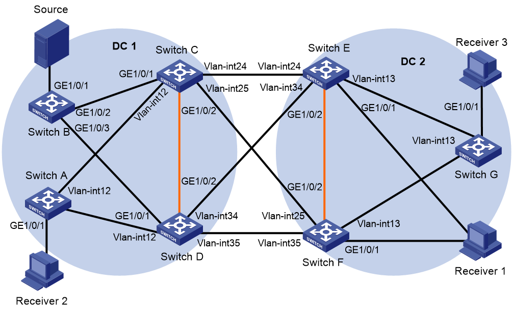
Table 1 Interfaces and IP address assignment
|
Device |
Interface |
IP address |
Device |
Interface |
IP address |
|
Switch A |
Loop0 |
1.1.1.1/32 |
Switch G |
Loop0 |
6.6.6.6/32 |
|
|
Loop1 |
1.1.1.1/32 |
|
Loop1 |
6.6.6.6/32 |
|
|
Vlan-int12 |
12.1.1.1/24 |
|
Vlan-int13 |
13.1.1.6/24 |
|
|
VSI-int1 |
192.168.59.2/24 |
|
VSI-int1 |
192.168.60.2/24 |
|
Switch C |
Loop0 |
2.2.2.2/32 |
Switch D |
Loop0 |
3.3.3.3/32 |
|
|
Loop1 |
2.2.2.2/32 |
|
Loop1 |
3.3.3.3/32 |
|
|
Loop2 |
1.2.3.4/32 |
|
Loop2 |
1.2.3.4/32 |
|
|
Vlan-int12 |
12.1.1.2/24 |
|
Vlan-int12 |
12.1.1.3/24 |
|
|
Vlan-int24 |
24.1.1.2/24 |
|
Vlan-int34 |
34.1.1.3/24 |
|
|
Vlan-int25 |
25.1.1.2/24 |
|
Vlan-int35 |
35.1.1.3/24 |
|
|
VSI-int1 |
192.168.57.2/24 |
|
VSI-int1 |
192.168.57.3/24 |
|
Switch E |
Loop0 |
4.4.4.4/32 |
Switch F |
Loop0 |
5.5.5.5/32 |
|
|
Loop1 |
4.4.4.4/32 |
|
Loop1 |
5.5.5.5/32 |
|
|
Loop2 |
5.6.7.8/32 |
|
Loop2 |
5.6.7.8/32 |
|
|
Vlan-int13 |
13.1.1.4/24 |
|
Vlan-int13 |
12.1.1.5/24 |
|
|
Vlan-int24 |
24.1.1.4/24 |
|
Vlan-int25 |
25.1.1.5/24 |
|
|
Vlan-int34 |
34.1.1.4/24 |
|
Vlan-int35 |
35.1.1.5/24 |
|
|
VSI-int1 |
192.168.58.2/24 |
|
VSI-int1 |
192.168.58.3/24 |
Procedure
1. On the multicast source, specify 192.168.57.1 as the gateway address. On Receiver 1, Receiver 2, and Receiver 3, specify 192.168.58.1, 192.168.59.1, and 192.168.60.1 as the gateway addresses, respectively. (Details not shown.)
2. Configure IP addresses, PIM SM, and unicast routing settings:
# Assign IP addresses to interfaces, as shown in Figure 15. (Details not shown.)
# Configure OSPF in each data center for the switches in a data center to reach one another. (Details not shown.)
# Enable PIM SM on the VLAN interfaces that interconnect the devices in a data center. (Details not shown.)
# Verify that PIM SM is disabled on the VLAN interfaces that interconnect the EDs. (Details not shown.)
3. Configure Switch A:
# Enable L2VPN and IP multicast routing, and create VLAN 11.
<SwitchA> system-view
[SwitchA] l2vpn enable
[SwitchA] multicast routing
[SwitchA-mrib] quit
[SwitchA] vlan 11
[SwitchA-vlan11] quit
# Enable the IGMP snooping feature.
[SwitchA] igmp-snooping
[SwitchA-igmp-snooping] quit
# Disable remote MAC address learning and remote ARP learning.
[SwitchA] vxlan tunnel mac-learning disable
[SwitchA] vxlan tunnel arp-learning disable
# Configure Loopback 0.
[SwitchA] interface loopback 0
[SwitchA-LoopBack0] ip address 1.1.1.1 32
[SwitchA-LoopBack0] pim sm
[SwitchA-LoopBack0] ospf 1 area 0.0.0.0
[SwitchA-LoopBack0] quit
# Create an EVPN instance on VSI vpna.
[SwitchA] vsi vpna
[SwitchA-vsi-vpna] evpn encapsulation vxlan
[SwitchA-vsi-vpna-evpn-vxlan] route-distinguisher auto
[SwitchA-vsi-vpna-evpn-vxlan] vpn-target auto
[SwitchA-vsi-vpna-evpn-vxlan] quit
# Enable IGMP snooping and IGMP snooping proxying on VSI vpna.
[SwitchA-vsi-vpna] igmp-snooping enable
[SwitchA-vsi-vpna] igmp-snooping proxy enable
# Create VXLAN 11.
[SwitchA-vsi-vpna] vxlan 11
[SwitchA-vsi-vpna-vxlan-11] quit
[SwitchA-vsi-vpna] quit
# Configure BGP to advertise BGP EVPN routes.
[SwitchA] bgp 100
[SwitchA-bgp-default] group evpn internal
[SwitchA-bgp-default] peer evpn connect-interface loopback 0
[SwitchA-bgp-default] peer 2.2.2.2 group evpn
[SwitchA-bgp-default] peer 3.3.3.3 group evpn
[SwitchA-bgp-default] address-family l2vpn evpn
[SwitchA-bgp-default-evpn] peer evpn enable
[SwitchA-bgp-default-evpn] peer evpn next-hop-local
[SwitchA-bgp-default-evpn] quit
[SwitchA-bgp-default] quit
# On GigabitEthernet 1/0/1, create Ethernet service instance 100 to match VLAN 11.
[SwitchA] interface gigabitethernet 1/0/1
[SwitchA-GigabitEthernet1/0/1] port link-type trunk
[SwitchA-GigabitEthernet1/0/1] port trunk permit vlan 1 11
[SwitchA-GigabitEthernet1/0/1] service-instance 100
[SwitchA-GigabitEthernet1/0/1-srv100] encapsulation s-vid 11
# Map Ethernet service instance 100 to VSI vpna.
[SwitchA-GigabitEthernet1/0/1-srv100] xconnect vsi vpna
[SwitchA-GigabitEthernet1/0/1-srv100] quit
# Configure RD and route target settings for VPN instance vpn1.
[SwitchA] ip vpn-instance vpn1
[SwitchA-vpn-instance-vpn1] route-distinguisher 1:1
[SwitchA-vpn-instance-vpn1] address-family ipv4
[SwitchA-vpn-ipv4-vpn1] vpn-target 2:2
[SwitchA-vpn-ipv4-vpn1] quit
[SwitchA-vpn-instance-vpn1] address-family evpn
[SwitchA-vpn-evpn-vpn1] vpn-target 1:1
[SwitchA-vpn-evpn-vpn1] quit
[SwitchA-vpn-instance-vpn1] quit
# Configure VSI-interface 1.
[SwitchA] interface vsi-interface 1
[SwitchA-Vsi-interface1] ip binding vpn-instance vpn1
[SwitchA-Vsi-interface1] ip address 192.168.59.2 255.255.255.0
[SwitchA-Vsi-interface1] pim sm
[SwitchA-Vsi-interface1] igmp enable
[SwitchA-Vsi-interface1] distributed-gateway local
[SwitchA-Vsi-interface1] quit
# Associate VSI-interface 2 with VPN instance vpn1, and configure the L3 VXLAN ID as 1000 for the VPN instance.
[SwitchA] interface vsi-interface 2
[SwitchA-Vsi-interface2] ip binding vpn-instance vpn1
[SwitchA-Vsi-interface2] l3-vni 1000
[SwitchA-Vsi-interface2] pim sm
[SwitchA-Vsi-interface2] quit
# Enable IP multicast routing for VPN instance vpn1.
[SwitchA] multicast routing vpn-instance vpn1
[SwitchA-mrib-vpn1] quit
# Create an MDT-based MVXLAN for VPN instance vpn1 and enter MVXLAN IPv4 address family view. Configure the default group, MVXLAN source interface, and data group range settings.
[SwitchA] multicast-vpn vxlan vpn-instance vpn1 mode mdt
[SwitchA-mvxlan-vpn1] address-family ipv4
[SwitchA-mvxlan-vpn1-ipv4] default-group 236.0.0.0
[SwitchA-mvxlan-vpn1-ipv4] source loopback 0
[SwitchA-mvxlan-vpn1-ipv4] data-group 239.0.0.0 24
[SwitchA-mvxlan-vpn1-ipv4] quit
[SwitchA-mvxlan-vpn1] quit
# Configure Loopback 1.
[SwitchA] interface loopback 1
[SwitchA-LoopBack1] ip binding vpn-instance vpn1
[SwitchA-LoopBack1] ip address 1.1.1.1 32
[SwitchA-LoopBack1] pim sm
[SwitchA-LoopBack1] quit
# Enter VPN instance PIM view, and configure Loopback 1 as a candidate-BSR and candidate-RP in VPN instance vpn1.
[SwitchA] pim vpn-instance vpn1
[SwitchA-pim-vpn1] c-bsr 1.1.1.1
[SwitchA-pim-vpn1] c-rp 1.1.1.1
[SwitchA-pim-vpn1] quit
# Specify VSI-interface 1 as the gateway interface for VSI vpna.
[SwitchA] vsi vpna
[SwitchA-vsi-vpna] gateway vsi-interface 1
[SwitchA-vsi-vpna] quit
4. Configure Switch B:
# Create Layer 2 aggregate interface Bridge-Aggregation 1, and set the link aggregation mode to dynamic.
<SwitchB> system-view
[SwitchB] interface bridge-aggregation 1
[SwitchB-Bridge-Aggregation1] link-aggregation mode dynamic
[SwitchB-Bridge-Aggregation1] quit
# Assign ports GigabitEthernet 1/0/2 and GigabitEthernet 1/0/3 to link aggregation group 1.
[SwitchB] interface range gigabitethernet 1/0/2 to gigabitethernet 1/0/3
[SwitchB-if-range] port link-aggregation group 1
[SwitchB-if-range] quit
# Create VLAN 11.
[SwitchB] vlan 11
[SwitchB-vlan11] quit
# Configure Layer 2 aggregate interface Bridge-Aggregation 1 as a trunk port and assign it to VLAN 11.
[SwitchB] interface Bridge-Aggregation 1
[SwitchB-Bridge-Aggregation1] port link-type trunk
[SwitchB-Bridge-Aggregation1] port trunk permit vlan 11
[SwitchB-Bridge-Aggregation1] quit
# Configure GigabitEthernet 1/0/1 as a trunk port and assign it to VLAN 11.
[SwitchB] interface gigabitethernet 1/0/1
[SwitchB-GigabitEthernet1/0/1] port link-type trunk
[SwitchB-GigabitEthernet1/0/1] port trunk permit vlan 11
[SwitchB-GigabitEthernet1/0/1] quit
5. Configure Switch C:
# Enable L2VPN, IP multicast routing, OSPF process 1, and RIP process 1.
<SwitchC> system-view
[SwitchC] l2vpn enable
[SwitchC] multicast routing
[SwitchC-mrib] quit
[SwitchC] pim
[SwitchC-pim] quit
[SwitchC] ospf 1
[SwitchC-ospf-1] area 0.0.0.0
[SwitchC-ospf-1-area-0.0.0.0] quit
[SwitchC-ospf-1] quit
[SwitchC] rip 1
[SwitchC-rip-1] quit
# Enable the IGMP snooping feature.
[SwitchC] igmp-snooping
[SwitchC-igmp-snooping] quit
# Create an EVPN instance on VSI vpna.
[SwitchC] vsi vpna
[SwitchC-vsi-vpna] evpn encapsulation vxlan
[SwitchC-vsi-vpna-evpn-vxlan] route-distinguisher auto
[SwitchC-vsi-vpna-evpn-vxlan] vpn-target auto
[SwitchC-vsi-vpna-evpn-vxlan] quit
# Enable IGMP snooping and IGMP snooping proxying on VSI vpna.
[SwitchC-vsi-vpna] igmp-snooping enable
[SwitchC-vsi-vpna] igmp-snooping proxy enable
# Create VXLAN 11.
[SwitchC-vsi-vpna] vxlan 11
[SwitchC-vsi-vpna-vxlan-11] quit
[SwitchC-vsi-vpna] quit
# On VLAN interface 24, enable RIP and DCI multicast.
[SwitchC] interface vlan-interface 24
[SwitchC-Vlan-interface24] rip 1 enable
[SwitchC-Vlan-interface24] dci enable
[SwitchC-Vlan-interface24] quit
# On VLAN interface 25, enable RIP and DCI multicast.
[SwitchC] interface vlan-interface 25
[SwitchC-Vlan-interface25] rip 1 enable
[SwitchC-Vlan-interface25] dci enable
[SwitchC-Vlan-interface25] quit
# Specify the virtual ED address as 1.2.3.4.
[SwitchC] evpn m-lag group 1.2.3.4
# Specify the IP addresses of the member devices in the M-LAG system.
[SwitchC] evpn m-lag local 2.2.2.2 remote 3.3.3.3
# Configure RD and route target settings for VPN instance vpn1.
[SwitchC] ip vpn-instance vpn1
[SwitchC-vpn-instance-vpn1] route-distinguisher 1:2
[SwitchC-vpn-instance-vpn1] address-family ipv4
[SwitchC-vpn-ipv4-vpn1] vpn-target 2:2
[SwitchC-vpn-ipv4-vpn1] quit
[SwitchC-vpn-instance-vpn1] address-family evpn
[SwitchC-vpn-evpn-vpn1] vpn-target 1:1
[SwitchC-vpn-evpn-vpn1] quit
[SwitchC-vpn-instance-vpn1] quit
# Configure Loopback 0.
[SwitchC] interface loopback 0
[SwitchC-LoopBack0] ip address 2.2.2.2 32
[SwitchC-LoopBack0] ospf 1 area 0.0.0.0
[SwitchC-LoopBack0] rip 1 enable
[SwitchC-LoopBack0] pim sm
# Configure Loopback 1.
[SwitchC] interface loopback 1
[SwitchC-LoopBack1] ip binding vpn-instance vpn1
[SwitchC-LoopBack1] ip address 2.2.2.2 32
[SwitchC-LoopBack1] pim sm
[SwitchC-LoopBack1] quit
# Configure Loopback 2.
[SwitchC] interface loopback 2
[SwitchC-LoopBack2] ip address 1.2.3.4 32
[SwitchC-LoopBack2] ospf 1 area 0.0.0.0
[SwitchC-LoopBack2] rip 1 enable
[SwitchC-LoopBack2] quit
# Configure VSI-interface 1.
[SwitchC] interface vsi-interface 1
[SwitchC-Vsi-interface1] ip binding vpn-instance vpn1
[SwitchC-Vsi-interface1] ip address 192.168.57.2 255.255.255.0
[SwitchC-Vsi-interface1] pim sm
[SwitchC-Vsi-interface1] igmp enable
[SwitchC-Vsi-interface1] distributed-gateway local
[SwitchC-Vsi-interface1] quit
# Associate VSI-interface 2 with VPN instance vpn1, and configure the L3 VXLAN ID as 1000 for the VPN instance.
[SwitchC] interface vsi-interface 2
[SwitchC-Vsi-interface2] ip binding vpn-instance vpn1
[SwitchC-Vsi-interface2] l3-vni 1000
[SwitchC-Vsi-interface2] pim sm
[SwitchC-Vsi-interface2] quit
# Create Layer 2 aggregate interface Bridge-Aggregation 1, and set the link aggregation mode to dynamic.
[SwitchC] interface bridge-aggregation 1
[SwitchC-Bridge-Aggregation1] link-aggregation mode dynamic
[SwitchC-Bridge-Aggregation1] quit
# Assign GigabitEthernet 1/0/1 to link aggregation group 1.
[SwitchC] interface gigabitethernet 1/0/1
[SwitchC-GigabitEthernet1/0/1] port link-aggregation group 1
[SwitchC-GigabitEthernet1/0/1] quit
# Assign the Layer 2 aggregate interface to M-LAG group 1, create Ethernet service instance 100, and configure the Ethernet service instance to match frames that have an outer 802.1Q VLAN ID of 11.
[SwitchC] interface bridge-aggregation 1
[SwitchC-Bridge-Aggregation1] port link-type trunk
[SwitchC-Bridge-Aggregation1] port trunk permit vlan 1 11
[SwitchC-Bridge-Aggregation1] port m-lag group 1
[SwitchC-Bridge-Aggregation1] service-instance 100
[SwitchC-Bridge-Aggregation1-srv100] encapsulation s-vid 11
# Map Ethernet service instance 100 to VSI vpna.
[SwitchC-Bridge-Aggregation1-srv100] xconnect vsi vpna
[SwitchC-Bridge-Aggregation1-srv100] quit
# Enable IP multicast routing in VPN instance vpn1.
[SwitchC] multicast routing vpn-instance vpn1
[SwitchC-mrib-vpn1] quit
# Enter VPN instance PIM view, and configure Loopback 1 as a candidate-BSR and candidate-RP in VPN instance vpn1.
[SwitchC] pim vpn-instance vpn1
[SwitchC-pim-vpn1] c-bsr 2.2.2.2
[SwitchC-pim-vpn1] c-rp 2.2.2.2
[SwitchC-pim-vpn1] quit
# Create an MDT-based MVXLAN for VPN instance vpn1 and enter MVXLAN IPv4 address family view. Configure the default group, MVXLAN source interface, and data group range settings. Enable advertising active multicast sources through S-PMSI routes, and enable DCI multicast.
[SwitchC] multicast-vpn vxlan vpn-instance vpn1 mode mdt
[SwitchC-mvxlan-vpn1] address-family ipv4
[SwitchC-mvxlan-vpn1-ipv4] default-group 236.0.0.0
[SwitchC-mvxlan-vpn1-ipv4] source loopback 2 evpn-mlag-group
[SwitchC-mvxlan-vpn1-ipv4] data-group 239.0.0.0 24
[SwitchC-mvxlan-vpn1-ipv4] s-pmsi advertise source-active
[SwitchC-mvxlan-vpn1-ipv4] dci enable
[SwitchC-mvxlan-vpn1-ipv4] quit
[SwitchC-mvxlan-vpn1] quit
# Specify the IP addresses of the member devices in the M-LAG system.
[SwitchC] evpn m-lag local 2.2.2.2 remote 3.3.3.3
# Configure a routing policy to meet the following requirements:
¡ Switch C does not forward SMET and S-PMSI routes from Switch D to Switch E or Switch F.
¡ Switch C modifies the next hop as 2.2.2.2 when receiving a SMET or S-PMSI route from a device other than Switch D.
[SwitchC] ip prefix-list 1 index 10 permit 0.0.0.0 0 less-equal 32
[SwitchC] ip prefix-list 2 index 10 permit 3.3.3.3 32
[SwitchC] route-policy 2 deny node 0
[SwitchC-route-policy-2-0] if-match ip route-source prefix-list 2
[SwitchC-route-policy-2-0] if-match route-type bgp-evpn-mac-ip bgp-evpn-imet bgp-evpn-ip-prefix
[SwitchC-route-policy-2-0] quit
[SwitchC] route-policy 2 deny node 1
[SwitchC-route-policy-2-1] if-match ip route-source prefix-list 2
[SwitchC-route-policy-2-1] if-match route-type bgp-evpn-smet bgp-evpn-s-pmsi
[SwitchC-route-policy-2-1] quit
[SwitchC] route-policy 2 permit node 2
[SwitchC-route-policy-2-2] if-match ip route-source prefix-list 1
[SwitchC-route-policy-2-2] if-match route-type bgp-evpn-smet bgp-evpn-s-pmsi
[SwitchC-route-policy-2-2] apply ip-address next-hop 2.2.2.2
[SwitchC-route-policy-2-2] quit
[SwitchC] route-policy 2 permit node 3
[SwitchC-route-policy-2-3] if-match ip route-source prefix-list 1
[SwitchC-route-policy-2-3] quit
# Configure another routing policy, so Switch C sends SMET and S-PMSI routes to only Switch D.
[SwitchC] route-policy 10 permit node 1
[SwitchC-route-policy-10-1] if-match ip route-source prefix-list 1
[SwitchC-route-policy-10-1] if-match route-type bgp-evpn-smet bgp-evpn-s-pmsi
[SwitchC-route-policy-10-1] quit
# Configure BGP to advertise EVPN routes, and set the virtual ED address as the next hop for the advertised routes.
[SwitchC] bgp 100
[SwitchC-bgp-default] peer 1.1.1.1 as-number 100
[SwitchC-bgp-default] peer 1.1.1.1 connect-interface loopback 0
[SwitchC-bgp-default] peer 3.3.3.3 as-number 100
[SwitchC-bgp-default] peer 3.3.3.3 connect-interface loopback 0
[SwitchC-bgp-default] peer 4.4.4.4 as-number 200
[SwitchC-bgp-default] peer 4.4.4.4 connect-interface loopback 0
[SwitchC-bgp-default] peer 4.4.4.4 ebgp-max-hop 64
[SwitchC-bgp-default] peer 5.5.5.5 as-number 200
[SwitchC-bgp-default] peer 5.5.5.5 connect-interface loopback 0
[SwitchC-bgp-default] peer 5.5.5.5 ebgp-max-hop 64
[SwitchC-bgp-default] address-family l2vpn evpn
[SwitchC-bgp-default-evpn] nexthop evpn-m-lag group-address
[SwitchC-bgp-default-evpn] peer 1.1.1.1 enable
[SwitchC-bgp-default-evpn] peer 1.1.1.1 next-hop-local
[SwitchC-bgp-default-evpn] peer 3.3.3.3 enable
[SwitchC-bgp-default-evpn] peer 3.3.3.3 next-hop-local
[SwitchC-bgp-default-evpn] peer 3.3.3.3 route-policy 10 export
[SwitchC-bgp-default-evpn] peer 4.4.4.4 enable
[SwitchC-bgp-default-evpn] peer 4.4.4.4 router-mac-local
[SwitchC-bgp-default-evpn] peer 4.4.4.4 route-policy 2 export
[SwitchC-bgp-default-evpn] peer 5.5.5.5 enable
[SwitchC-bgp-default-evpn] peer 5.5.5.5 router-mac-local
[SwitchC-bgp-default-evpn] peer 5.5.5.5 route-policy 2 export
[SwitchC-bgp-default-evpn] quit
[SwitchC-bgp-default] quit
# Configure Layer 2 dynamic aggregate interface Bridge-Aggregation 9, and specify it as the peer-link interface.
[SwitchC] interface bridge-aggregation 9
[SwitchC-Bridge-Aggregation9] port link-type trunk
[SwitchC-Bridge-Aggregation9] port trunk permit vlan all
[SwitchC-Bridge-Aggregation9] link-aggregation mode dynamic
[SwitchC-Bridge-Aggregation9] port m-lag peer-link 1
[SwitchC-Bridge-Aggregation9] quit
# Assign GigabitEthernet 1/0/2 to link aggregation group 9.
[SwitchC] interface gigabitethernet 1/0/2
[SwitchC-GigabitEthernet1/0/2] port link-aggregation group 9
[SwitchC-GigabitEthernet1/0/2] quit
# Configure M-LAG system settings.
[SwitchC] m-lag restore-delay 180
[SwitchC] m-lag system-mac 0001-0001-0001
[SwitchC] m-lag system-number 1
[SwitchC] m-lag system-priority 10
# Specify VSI-interface 1 as the gateway interface for VSI vpna.
[SwitchC] vsi vpna
[SwitchC-vsi-vpna] gateway vsi-interface 1
[SwitchC-vsi-vpna] quit
6. Configure Switch D:
# Enable L2VPN, IP multicast routing, OSPF process 1, and RIP process 1.
<SwitchD> system-view
[SwitchD] l2vpn enable
[SwitchD] multicast routing
[SwitchD-mrib] quit
[SwitchD] pim
[SwitchD-pim] quit
[SwitchD] ospf 1
[SwitchD-ospf-1] area 0.0.0.0
[SwitchD-ospf-1-area-0.0.0.0] quit
[SwitchD-ospf-1] quit
[SwitchD] rip 1
[SwitchD-rip-1] quit
# Enable the IGMP snooping feature.
[SwitchD] igmp-snooping
[SwitchD-igmp-snooping] quit
# Create an EVPN instance on VSI vpna.
[SwitchD] vsi vpna
[SwitchD-vsi-vpna] evpn encapsulation vxlan
[SwitchD-vsi-vpna-evpn-vxlan] route-distinguisher auto
[SwitchD-vsi-vpna-evpn-vxlan] vpn-target auto
[SwitchD-vsi-vpna-evpn-vxlan] quit
# Enable IGMP snooping and IGMP snooping proxying on VSI vpna.
[SwitchD-vsi-vpna] igmp-snooping enable
[SwitchD-vsi-vpna] igmp-snooping proxy enable
# Create VXLAN 11.
[SwitchD-vsi-vpna] vxlan 11
[SwitchD-vsi-vpna-vxlan-11] quit
[SwitchD-vsi-vpna] quit
# On VLAN interface 34, enable RIP and DCI multicast.
[SwitchD] interface vlan-interface 34
[SwitchD-Vlan-interface34] rip 1 enable
[SwitchD-Vlan-interface34] dci enable
[SwitchD-Vlan-interface34] quit
# On VLAN interface 35, enable RIP and DCI multicast.
[SwitchD] interface vlan-interface 35
[SwitchD-Vlan-interface35] rip 1 enable
[SwitchD-Vlan-interface35] dci enable
[SwitchD-Vlan-interface35] quit
# Specify the virtual ED address as 1.2.3.4.
[SwitchD] evpn m-lag group 1.2.3.4
# Specify the IP addresses of the member devices in the M-LAG system.
[SwitchD] evpn m-lag local 3.3.3.3 remote 2.2.2.2
# Configure RD and route target settings for VPN instance vpn1.
[SwitchD] ip vpn-instance vpn1
[SwitchD-vpn-instance-vpn1] route-distinguisher 1:3
[SwitchD-vpn-instance-vpn1] address-family ipv4
[SwitchD-vpn-ipv4-vpn1] vpn-target 2:2
[SwitchD-vpn-ipv4-vpn1] quit
[SwitchD-vpn-instance-vpn1] address-family evpn
[SwitchD-vpn-evpn-vpn1] vpn-target 1:1
[SwitchD-vpn-evpn-vpn1] quit
[SwitchD-vpn-instance-vpn1] quit
# Configure Loopback 0.
[SwitchD] interface loopback 0
[SwitchD-LoopBack0] ip address 3.3.3.3 32
[SwitchD-LoopBack0] ospf 1 area 0.0.0.0
[SwitchD-LoopBack0] rip 1 enable
[SwitchD-LoopBack0] pim sm
# Configure Loopback 1.
[SwitchD] interface loopback 1
[SwitchD-LoopBack1] ip binding vpn-instance vpn1
[SwitchD-LoopBack1] ip address 3.3.3.3 32
[SwitchD-LoopBack1] pim sm
[SwitchD-LoopBack1] quit
# Configure Loopback 2.
[SwitchD] interface loopback 2
[SwitchD-LoopBack2] ip address 1.2.3.4 32
[SwitchD-LoopBack2] ospf 1 area 0.0.0.0
[SwitchD-LoopBack2] rip 1 enable
[SwitchD-LoopBack2] quit
# Configure VSI-interface 1.
[SwitchD] interface vsi-interface 1
[SwitchD-Vsi-interface1] ip binding vpn-instance vpn1
[SwitchD-Vsi-interface1] ip address 192.168.57.3 255.255.255.0
[SwitchD-Vsi-interface1] pim sm
[SwitchD-Vsi-interface1] igmp enable
[SwitchD-Vsi-interface1] distributed-gateway local
[SwitchD-Vsi-interface1] quit
# Associate VSI-interface 2 with VPN instance vpn1, and configure the L3 VXLAN ID as 1000 for the VPN instance.
[SwitchD] interface vsi-interface 2
[SwitchD-Vsi-interface2] ip binding vpn-instance vpn1
[SwitchD-Vsi-interface2] l3-vni 1000
[SwitchD-Vsi-interface2] pim sm
[SwitchD-Vsi-interface2] quit
# Create Layer 2 aggregate interface Bridge-Aggregation 1, and set the link aggregation mode to dynamic.
[SwitchD] interface bridge-aggregation 1
[SwitchD-Bridge-Aggregation1] link-aggregation mode dynamic
[SwitchD-Bridge-Aggregation1] quit
# Assign GigabitEthernet 1/0/1 to link aggregation group 1.
[SwitchD] interface gigabitethernet 1/0/1
[SwitchD-GigabitEthernet1/0/1] port link-aggregation group 1
[SwitchD-GigabitEthernet1/0/1] quit
# Assign the Layer 2 aggregate interface to M-LAG group 1, create Ethernet service instance 100, and configure the Ethernet service instance to match frames that have an outer 802.1Q VLAN ID of 11.
[SwitchD] interface bridge-aggregation 1
[SwitchD-Bridge-Aggregation1] port link-type trunk
[SwitchD-Bridge-Aggregation1] port trunk permit vlan 1 11
[SwitchD-Bridge-Aggregation1] port m-lag group 1
[SwitchD-Bridge-Aggregation1] service-instance 100
[SwitchD-Bridge-Aggregation1-srv100] encapsulation s-vid 11
# Map Ethernet service instance 100 to VSI vpna.
[SwitchD-Bridge-Aggregation1-srv100] xconnect vsi vpna
[SwitchD-Bridge-Aggregation1-srv100] quit
# Enable IP multicast routing in VPN instance vpn1.
[SwitchD] multicast routing vpn-instance vpn1
[SwitchD-mrib-vpn1] quit
# Enter VPN instance PIM view, and configure Loopback 1 as a candidate-BSR and candidate-RP in VPN instance vpn1.
[SwitchD] pim vpn-instance vpn1
[SwitchD-pim-vpn1] c-bsr 3.3.3.3
[SwitchD-pim-vpn1] c-rp 3.3.3.3
[SwitchD-pim-vpn1] quit
# Create an MDT-based MVXLAN for VPN instance vpn1 and enter MVXLAN IPv4 address family view. Configure the default group, MVXLAN source interface, and data group range settings. Enable advertising active multicast sources through S-PMSI routes, and enable DCI multicast.
[SwitchD] multicast-vpn vxlan vpn-instance vpn1 mode mdt
[SwitchD-mvxlan-vpn1] address-family ipv4
[SwitchD-mvxlan-vpn1-ipv4] default-group 236.0.0.0
[SwitchD-mvxlan-vpn1-ipv4] source loopback 2 evpn-mlag-group
[SwitchD-mvxlan-vpn1-ipv4] data-group 239.0.0.0 24
[SwitchD-mvxlan-vpn1-ipv4] s-pmsi advertise source-active
[SwitchD-mvxlan-vpn1-ipv4] dci enable
[SwitchD-mvxlan-vpn1-ipv4] quit
[SwitchD-mvxlan-vpn1] quit
# Specify the IP addresses of the member devices in the M-LAG system.
[SwitchD] evpn m-lag local 3.3.3.3 remote 2.2.2.2
# Configure a routing policy to meet the following requirements:
¡ Switch D does not forward SMET and S-PMSI routes from Switch C to Switch E or Switch F.
¡ Switch D modifies the next hop as 3.3.3.3 when receiving a SMET or S-PMSI route from a device other than Switch C.
[SwitchD] ip prefix-list 1 index 10 permit 0.0.0.0 0 less-equal 32
[SwitchD] ip prefix-list 2 index 10 permit 2.2.2.2 32
[SwitchD] route-policy 3 deny node 0
[SwitchD-route-policy-3-0] if-match ip route-source prefix-list 2
[SwitchD-route-policy-3-0] if-match route-type bgp-evpn-mac-ip bgp-evpn-imet bgp-evpn-ip-prefix
[SwitchD-route-policy-3-0] quit
[SwitchD] route-policy 3 deny node 1
[SwitchD-route-policy-3-1] if-match ip route-source prefix-list 2
[SwitchD-route-policy-3-1] if-match route-type bgp-evpn-smet bgp-evpn-s-pmsi
[SwitchD-route-policy-3-1] quit
[SwitchD] route-policy 3 permit node 2
[SwitchD-route-policy-3-2] if-match ip route-source prefix-list 1
[SwitchD-route-policy-3-2] if-match route-type bgp-evpn-smet bgp-evpn-s-pmsi
[SwitchD-route-policy-3-2] apply ip-address next-hop 3.3.3.3
[SwitchD-route-policy-3-2] quit
[SwitchD] route-policy 3 permit node 3
[SwitchD-route-policy-3-3] if-match ip route-source prefix-list 1
[SwitchD-route-policy-3-3] quit
# Configure another routing policy, so Switch D send SMET and S-PMSI routes to only Switch C.
[SwitchD] route-policy 10 permit node 1
[SwitchD-route-policy-10-1] if-match ip route-source prefix-list 1
[SwitchD-route-policy-10-1] if-match route-type bgp-evpn-smet bgp-evpn-s-pmsi
[SwitchD-route-policy-10-1] quit
# Configure BGP to advertise EVPN routes, and set the virtual ED address as the next hop for the advertised routes.
[SwitchD] bgp 100
[SwitchD-bgp-default] peer 1.1.1.1 as-number 100
[SwitchD-bgp-default] peer 1.1.1.1 connect-interface loopback 0
[SwitchD-bgp-default] peer 2.2.2.2 as-number 100
[SwitchD-bgp-default] peer 2.2.2.2 connect-interface loopback 0
[SwitchD-bgp-default] peer 4.4.4.4 as-number 200
[SwitchD-bgp-default] peer 4.4.4.4 connect-interface loopback 0
[SwitchD-bgp-default] peer 4.4.4.4 ebgp-max-hop 64
[SwitchD-bgp-default] peer 5.5.5.5 as-number 200
[SwitchD-bgp-default] peer 5.5.5.5 connect-interface loopback 0
[SwitchD-bgp-default] peer 5.5.5.5 ebgp-max-hop 64
[SwitchD-bgp-default] address-family l2vpn evpn
[SwitchD-bgp-default-evpn] nexthop evpn-m-lag group-address
[SwitchD-bgp-default-evpn] peer 1.1.1.1 enable
[SwitchD-bgp-default-evpn] peer 1.1.1.1 next-hop-local
[SwitchD-bgp-default-evpn] peer 2.2.2.2 enable
[SwitchD-bgp-default-evpn] peer 2.2.2.2 next-hop-local
[SwitchD-bgp-default-evpn] peer 2.2.2.2 route-policy 10 export
[SwitchD-bgp-default-evpn] peer 4.4.4.4 enable
[SwitchD-bgp-default-evpn] peer 4.4.4.4 router-mac-local
[SwitchD-bgp-default-evpn] peer 4.4.4.4 route-policy 3 export
[SwitchD-bgp-default-evpn] peer 5.5.5.5 enable
[SwitchD-bgp-default-evpn] peer 5.5.5.5 router-mac-local
[SwitchD-bgp-default-evpn] peer 5.5.5.5 route-policy 3 export
[SwitchD-bgp-default-evpn] quit
[SwitchD-bgp-default] quit
# Configure Layer 2 dynamic aggregate interface Bridge-Aggregation 9, and specify it as the peer-link interface.
[SwitchD] interface bridge-aggregation 9
[SwitchD-Bridge-Aggregation9] port link-type trunk
[SwitchD-Bridge-Aggregation9] port trunk permit vlan all
[SwitchD-Bridge-Aggregation9] link-aggregation mode dynamic
[SwitchD-Bridge-Aggregation9] port m-lag peer-link 1
[SwitchD-Bridge-Aggregation9] quit
# Assign GigabitEthernet 1/0/2 to link aggregation group 9.
[SwitchD] interface gigabitethernet 1/0/2
[SwitchD-GigabitEthernet1/0/2] port link-aggregation group 9
[SwitchD-GigabitEthernet1/0/2] quit
# Configure M-LAG system settings.
[SwitchD] m-lag restore-delay 180
[SwitchD] m-lag system-mac 0001-0001-0001
[SwitchD] m-lag system-number 2
[SwitchD] m-lag system-priority 10
# Specify VSI-interface 1 as the gateway interface for VSI vpna.
[SwitchD] vsi vpna
[SwitchD-vsi-vpna] gateway vsi-interface 1
[SwitchD-vsi-vpna] quit
7. Configure Switch E:
# Enable L2VPN, IP multicast routing, OSPF process 1, and RIP process 1.
<SwitchE> system-view
[SwitchE] l2vpn enable
[SwitchE] multicast routing
[SwitchE-mrib] quit
[SwitchE] pim
[SwitchE-pim] quit
[SwitchE] ospf 1
[SwitchE-ospf-1] area 0.0.0.0
[SwitchE-ospf-1-area-0.0.0.0] quit
[SwitchE-ospf-1] quit
[SwitchE] rip 1
[SwitchE-rip-1] quit
# Enable the IGMP snooping feature.
[SwitchE] igmp-snooping
[SwitchE-igmp-snooping] quit
# Create an EVPN instance on VSI vpna.
[SwitchE] vsi vpna
[SwitchE-vsi-vpna] evpn encapsulation vxlan
[SwitchE-vsi-vpna-evpn-vxlan] route-distinguisher auto
[SwitchE-vsi-vpna-evpn-vxlan] vpn-target auto
[SwitchE-vsi-vpna-evpn-vxlan] quit
# Enable IGMP snooping and IGMP snooping proxying on VSI vpna.
[SwitchE-vsi-vpna] igmp-snooping enable
[SwitchE-vsi-vpna] igmp-snooping proxy enable
# Create VXLAN 11.
[SwitchE-vsi-vpna] vxlan 11
[SwitchE-vsi-vpna-vxlan-11] quit
[SwitchE-vsi-vpna] quit
# On VLAN interface 24, enable RIP and DCI multicast.
[SwitchE] interface vlan-interface 24
[SwitchE-Vlan-interface24] rip 1 enable
[SwitchE-Vlan-interface24] dci enable
[SwitchE-Vlan-interface24] quit
# On VLAN interface 34, enable RIP and DCI multicast.
[SwitchE] interface vlan-interface 34
[SwitchE-Vlan-interface34] rip 1 enable
[SwitchE-Vlan-interface34] dci enable
[SwitchE-Vlan-interface34] quit
# Specify the virtual ED address as 5.6.7.8.
[SwitchE] evpn m-lag group 5.6.7.8
# Specify the IP addresses of the member devices in the M-LAG system.
[SwitchE] evpn m-lag local 4.4.4.4 remote 5.5.5.5
# Configure RD and route target settings for VPN instance vpn1.
[SwitchE] ip vpn-instance vpn1
[SwitchE-vpn-instance-vpn1] route-distinguisher 1:4
[SwitchE-vpn-instance-vpn1] address-family ipv4
[SwitchE-vpn-ipv4-vpn1] vpn-target 2:2
[SwitchE-vpn-ipv4-vpn1] quit
[SwitchE-vpn-instance-vpn1] address-family evpn
[SwitchE-vpn-evpn-vpn1] vpn-target 1:1
[SwitchE-vpn-evpn-vpn1] quit
[SwitchE-vpn-instance-vpn1] quit
# Configure Loopback 0.
[SwitchE] interface loopback 0
[SwitchE-LoopBack0] ip address 4.4.4.4 32
[SwitchE-LoopBack0] ospf 1 area 0.0.0.0
[SwitchE-LoopBack0] rip 1 enable
[SwitchE-LoopBack0] pim sm
# Configure Loopback 1.
[SwitchE] interface loopback 1
[SwitchE-LoopBack1] ip binding vpn-instance vpn1
[SwitchE-LoopBack1] ip address 4.4.4.4 32
[SwitchE-LoopBack1] pim sm
[SwitchE-LoopBack1] quit
# Configure Loopback 2.
[SwitchE] interface loopback 2
[SwitchE-LoopBack2] ip address 5.6.7.8 32
[SwitchE-LoopBack2] ospf 1 area 0.0.0.0
[SwitchE-LoopBack2] rip 1 enable
[SwitchE-LoopBack2] quit
# Configure VSI-interface 1.
[SwitchE] interface vsi-interface 1
[SwitchE-Vsi-interface1] ip binding vpn-instance vpn1
[SwitchE-Vsi-interface1] ip address 192.168.58.2 255.255.255.0
[SwitchE-Vsi-interface1] pim sm
[SwitchE-Vsi-interface1] igmp enable
[SwitchE-Vsi-interface1] distributed-gateway local
[SwitchE-Vsi-interface1] quit
# Associate VSI-interface 2 with VPN instance vpn1, and configure the L3 VXLAN ID as 1000 for the VPN instance.
[SwitchE] interface vsi-interface 2
[SwitchE-Vsi-interface2] ip binding vpn-instance vpn1
[SwitchE-Vsi-interface2] l3-vni 1000
[SwitchE-Vsi-interface2] pim sm
[SwitchE-Vsi-interface2] quit
# Create Ethernet service instance 100 on GigabitEthernet 1/0/1, and configure the Ethernet service instance to match frames that have an outer 802.1Q VLAN ID of 11.
[SwitchE] interface gigabitethernet 1/0/1
[SwitchE-GigabitEthernet1/0/1] port link-type trunk
[SwitchE-GigabitEthernet1/0/1] port trunk permit vlan 1 11
[SwitchE-GigabitEthernet1/0/1] service-instance 100
[SwitchE-GigabitEthernet1/0/1-srv100] encapsulation s-vid 11
# Map Ethernet service instance 100 to VSI vpna.
[SwitchE-GigabitEthernet1/0/1-srv100] xconnect vsi vpna
[SwitchE-GigabitEthernet1/0/1-srv100] quit
# Enable IP multicast routing in VPN instance vpn1.
[SwitchE] multicast routing vpn-instance vpn1
[SwitchE-mrib-vpn1] quit
# Enter VPN instance PIM view, and configure Loopback 1 as a candidate-BSR and candidate-RP in VPN instance vpn1.
[SwitchE] pim vpn-instance vpn1
[SwitchE-pim-vpn1] c-bsr 4.4.4.4
[SwitchE-pim-vpn1] c-rp 4.4.4.4
[SwitchE-pim-vpn1] quit
# Create an MDT-based MVXLAN for VPN instance vpn1 and enter MVXLAN IPv4 address family view. Configure the default group, MVXLAN source interface, and data group range settings. Enable advertising active multicast sources through S-PMSI routes, and enable DCI multicast.
[SwitchE] multicast-vpn vxlan vpn-instance vpn1 mode mdt
[SwitchE-mvxlan-vpn1] address-family ipv4
[SwitchE-mvxlan-vpn1-ipv4] default-group 236.0.0.0
[SwitchE-mvxlan-vpn1-ipv4] source loopback 2 evpn-mlag-group
[SwitchE-mvxlan-vpn1-ipv4] data-group 239.0.0.0 24
[SwitchE-mvxlan-vpn1-ipv4] s-pmsi advertise source-active
[SwitchE-mvxlan-vpn1-ipv4] dci enable
[SwitchE-mvxlan-vpn1-ipv4] quit
[SwitchE-mvxlan-vpn1] quit
# Specify the IP addresses of the member devices in the M-LAG system.
[SwitchE] evpn m-lag local 4.4.4.4 remote 5.5.5.5
# Configure a routing policy to meet the following requirements:
¡ Switch E does not forward SMET and S-PMSI routes from Switch F to Switch C or Switch D.
¡ Switch E modifies the next hop as 4.4.4.4 when receiving a SMET or S-PMSI route from a device other than Switch F.
[SwitchE] ip prefix-list 1 index 10 permit 0.0.0.0 0 less-equal 32
[SwitchE] ip prefix-list 2 index 10 permit 5.5.5.5 32
[SwitchE] route-policy 4 deny node 0
[SwitchE-route-policy-4-0] if-match ip route-source prefix-list 2
[SwitchE-route-policy-4-0] if-match route-type bgp-evpn-mac-ip bgp-evpn-imet bgp-evpn-ip-prefix
[SwitchE-route-policy-4-0] quit
[SwitchE] route-policy 4 deny node 1
[SwitchE-route-policy-4-1] if-match ip route-source prefix-list 2
[SwitchE-route-policy-4-1] if-match route-type bgp-evpn-smet bgp-evpn-s-pmsi
[SwitchE-route-policy-4-1] quit
[SwitchE] route-policy 4 permit node 2
[SwitchE-route-policy-4-2] if-match ip route-source prefix-list 1
[SwitchE-route-policy-4-2] if-match route-type bgp-evpn-smet bgp-evpn-s-pmsi
[SwitchE-route-policy-4-2] apply ip-address next-hop 4.4.4.4
[SwitchE-route-policy-4-2] quit
[SwitchE] route-policy 4 permit node 3
[SwitchE-route-policy-4-3] if-match ip route-source prefix-list 1
[SwitchE-route-policy-4-3] quit
# Configure another routing policy, so Switch E sends SMET and S-PMSI routes to only Switch F.
[SwitchE] route-policy 10 permit node 1
[SwitchE-route-policy-10-1] if-match ip route-source prefix-list 1
[SwitchE-route-policy-10-1] if-match route-type bgp-evpn-smet bgp-evpn-s-pmsi
[SwitchE-route-policy-10-1] quit
# Configure BGP to advertise EVPN routes, and set the virtual ED address as the next hop for the advertised routes.
[SwitchE] bgp 200
[SwitchE-bgp-default] peer 5.5.5.5 as-number 200
[SwitchE-bgp-default] peer 5.5.5.5 connect-interface loopback 0
[SwitchE-bgp-default] peer 6.6.6.6 as-number 200
[SwitchE-bgp-default] peer 6.6.6.6 connect-interface loopback 0
[SwitchE-bgp-default] peer 2.2.2.2 as-number 100
[SwitchE-bgp-default] peer 2.2.2.2 connect-interface loopback 0
[SwitchE-bgp-default] peer 2.2.2.2 ebgp-max-hop 64
[SwitchE-bgp-default] peer 3.3.3.3 as-number 100
[SwitchE-bgp-default] peer 3.3.3.3 connect-interface loopback 0
[SwitchE-bgp-default] peer 3.3.3.3 ebgp-max-hop 64
[SwitchE-bgp-default] address-family l2vpn evpn
[SwitchE-bgp-default-evpn] nexthop evpn-m-lag group-address
[SwitchE-bgp-default-evpn] peer 5.5.5.5 enable
[SwitchE-bgp-default-evpn] peer 5.5.5.5 next-hop-local
[SwitchE-bgp-default-evpn] peer 5.5.5.5 route-policy 10 export
[SwitchE-bgp-default-evpn] peer 6.6.6.6 enable
[SwitchE-bgp-default-evpn] peer 6.6.6.6 next-hop-local
[SwitchE-bgp-default-evpn] peer 2.2.2.2 enable
[SwitchE-bgp-default-evpn] peer 2.2.2.2 router-mac-local
[SwitchE-bgp-default-evpn] peer 2.2.2.2 route-policy 4 export
[SwitchE-bgp-default-evpn] peer 3.3.3.3 enable
[SwitchE-bgp-default-evpn] peer 3.3.3.3 router-mac-local
[SwitchE-bgp-default-evpn] peer 3.3.3.3 route-policy 4 export
[SwitchE-bgp-default-evpn] quit
[SwitchE-bgp-default] quit
# Configure Layer 2 dynamic aggregate interface Bridge-Aggregation 9, and specify it as the peer-link interface.
[SwitchE] interface bridge-aggregation 9
[SwitchE-Bridge-Aggregation9] port link-type trunk
[SwitchE-Bridge-Aggregation9] port trunk permit vlan all
[SwitchE-Bridge-Aggregation9] link-aggregation mode dynamic
[SwitchE-Bridge-Aggregation9] port m-lag peer-link 1
[SwitchE-Bridge-Aggregation9] quit
# Assign GigabitEthernet 1/0/2 to link aggregation group 9.
[SwitchE] interface gigabitethernet 1/0/2
[SwitchE-GigabitEthernet1/0/2] port link-aggregation group 9
[SwitchE-GigabitEthernet1/0/2] quit
# Configure M-LAG system settings.
[SwitchE] m-lag restore-delay 180
[SwitchE] m-lag system-mac 0002-0002-0002
[SwitchE] m-lag system-number 1
[SwitchE] m-lag system-priority 10
# Specify VSI-interface 1 as the gateway interface for VSI vpna.
[SwitchE] vsi vpna
[SwitchE-vsi-vpna] gateway vsi-interface 1
[SwitchE-vsi-vpna] quit
8. Configure Switch F:
# Enable L2VPN, IP multicast routing, OSPF process 1, and RIP process 1.
<SwitchF> system-view
[SwitchF] l2vpn enable
[SwitchF] multicast routing
[SwitchF-mrib] quit
[SwitchF] pim
[SwitchF-pim] quit
[SwitchF] ospf 1
[SwitchF-ospf-1] area 0.0.0.0
[SwitchF-ospf-1-area-0.0.0.0] quit
[SwitchF-ospf-1] quit
[SwitchF] rip 1
[SwitchF-rip-1] quit
# Enable the IGMP snooping feature.
[SwitchF] igmp-snooping
[SwitchF-igmp-snooping] quit
# Create an EVPN instance on VSI vpna.
[SwitchF] vsi vpna
[SwitchF-vsi-vpna] evpn encapsulation vxlan
[SwitchF-vsi-vpna-evpn-vxlan] route-distinguisher auto
[SwitchF-vsi-vpna-evpn-vxlan] vpn-target auto
[SwitchF-vsi-vpna-evpn-vxlan] quit
# Enable IGMP snooping and IGMP snooping proxying on VSI vpna.
[SwitchF-vsi-vpna] igmp-snooping enable
[SwitchF-vsi-vpna] igmp-snooping proxy enable
# Create VXLAN 11.
[SwitchF-vsi-vpna] vxlan 11
[SwitchF-vsi-vpna-vxlan-11] quit
[SwitchF-vsi-vpna] quit
# On VLAN interface 25, enable RIP and DCI multicast.
[SwitchF] interface vlan-interface 25
[SwitchF-Vlan-interface25] rip 1 enable
[SwitchF-Vlan-interface25] dci enable
[SwitchF-Vlan-interface25] quit
# On VLAN interface 35, enable RIP and DCI multicast.
[SwitchF] interface vlan-interface 35
[SwitchF-Vlan-interface35] rip 1 enable
[SwitchF-Vlan-interface35] dci enable
[SwitchF-Vlan-interface35] quit
# Specify the virtual ED address as 5.6.7.8.
[SwitchF] evpn m-lag group 5.6.7.8
# Specify the IP addresses of the member devices in the M-LAG system.
[SwitchF] evpn m-lag local 5.5.5.5 remote 4.4.4.4
# Configure RD and route target settings for VPN instance vpn1.
[SwitchF] ip vpn-instance vpn1
[SwitchF-vpn-instance-vpn1] route-distinguisher 1:5
[SwitchF-vpn-instance-vpn1] address-family ipv4
[SwitchF-vpn-ipv4-vpn1] vpn-target 2:2
[SwitchF-vpn-ipv4-vpn1] quit
[SwitchF-vpn-instance-vpn1] address-family evpn
[SwitchF-vpn-evpn-vpn1] vpn-target 1:1
[SwitchF-vpn-evpn-vpn1] quit
[SwitchF-vpn-instance-vpn1] quit
# Configure Loopback 0.
[SwitchF] interface loopback 0
[SwitchF-LoopBack0] ip address 5.5.5.5 32
[SwitchF-LoopBack0] ospf 1 area 0.0.0.0
[SwitchF-LoopBack0] rip 1 enable
[SwitchF-LoopBack0] pim sm
# Configure Loopback 1.
[SwitchF] interface loopback 1
[SwitchF-LoopBack1] ip binding vpn-instance vpn1
[SwitchF-LoopBack1] ip address 5.5.5.5 32
[SwitchF-LoopBack1] pim sm
[SwitchF-LoopBack1] quit
# Configure Loopback 2.
[SwitchF] interface loopback 2
[SwitchF-LoopBack2] ip address 5.6.7.8 32
[SwitchF-LoopBack2] ospf 1 area 0.0.0.0
[SwitchF-LoopBack2] rip 1 enable
[SwitchF-LoopBack2] quit
# Configure VSI-interface 1.
[SwitchF] interface vsi-interface 1
[SwitchF-Vsi-interface1] ip binding vpn-instance vpn1
[SwitchF-Vsi-interface1] ip address 192.168.58.3 255.255.255.0
[SwitchF-Vsi-interface1] pim sm
[SwitchF-Vsi-interface1] igmp enable
[SwitchF-Vsi-interface1] distributed-gateway local
[SwitchF-Vsi-interface1] quit
# Associate VSI-interface 2 with VPN instance vpn1, and configure the L3 VXLAN ID as 1000 for the VPN instance.
[SwitchF] interface vsi-interface 2
[SwitchF-Vsi-interface2] ip binding vpn-instance vpn1
[SwitchF-Vsi-interface2] l3-vni 1000
[SwitchF-Vsi-interface2] pim sm
[SwitchF-Vsi-interface2] quit
# Create Ethernet service instance 100 on GigabitEthernet 1/0/1, and configure the Ethernet service instance to match frames that have an outer 802.1Q VLAN ID of 11.
[SwitchF] interface gigabitethernet 1/0/1
[SwitchF-GigabitEthernet1/0/1] port link-type trunk
[SwitchF-GigabitEthernet1/0/1] port trunk permit vlan 1 11
[SwitchF-GigabitEthernet1/0/1] service-instance 100
[SwitchF-GigabitEthernet1/0/1-srv100] encapsulation s-vid 11
# Map Ethernet service instance 100 to VSI vpna.
[SwitchF-GigabitEthernet1/0/1-srv100] xconnect vsi vpna
[SwitchF-GigabitEthernet1/0/1-srv100] quit
# Enable IP multicast routing in VPN instance vpn1.
[SwitchF] multicast routing vpn-instance vpn1
[SwitchF-mrib-vpn1] quit
# Enter VPN instance PIM view, and configure Loopback 1 as a candidate-BSR and candidate-RP in VPN instance vpn1.
[SwitchF] pim vpn-instance vpn1
[SwitchF-pim-vpn1] c-bsr 5.5.5.5
[SwitchF-pim-vpn1] c-rp 5.5.5.5
[SwitchF-pim-vpn1] quit
# Create an MDT-based MVXLAN for VPN instance vpn1 and enter MVXLAN IPv4 address family view. Configure the default group, MVXLAN source interface, and data group range settings. Enable advertising active multicast sources through S-PMSI routes, and enable DCI multicast.
[SwitchF] multicast-vpn vxlan vpn-instance vpn1 mode mdt
[SwitchF-mvxlan-vpn1] address-family ipv4
[SwitchF-mvxlan-vpn1-ipv4] default-group 236.0.0.0
[SwitchF-mvxlan-vpn1-ipv4] source loopback 2 evpn-mlag-group
[SwitchF-mvxlan-vpn1-ipv4] data-group 239.0.0.0 24
[SwitchF-mvxlan-vpn1-ipv4] s-pmsi advertise source-active
[SwitchF-mvxlan-vpn1-ipv4] dci enable
[SwitchF-mvxlan-vpn1-ipv4] quit
[SwitchF-mvxlan-vpn1] quit
# Specify the IP addresses of the member devices in the M-LAG system.
[SwitchF] evpn m-lag local 5.5.5.5 remote 4.4.4.4
# Configure a routing policy to meet the following requirements:
¡ Switch F does not forward SMET and S-PMSI routes from Switch E to Switch C or Switch D.
¡ Switch F modifies the next hop as 5.5.5.5 when receiving a SMET or S-PMSI route from a device other than Switch E.
[SwitchF] ip prefix-list 1 index 10 permit 0.0.0.0 0 less-equal 32
[SwitchF] ip prefix-list 2 index 10 permit 5.5.5.5 32
[SwitchF] route-policy 5 deny node 0
[SwitchF-route-policy-5-0] if-match ip route-source prefix-list 2
[SwitchF-route-policy-5-0] if-match route-type bgp-evpn-mac-ip bgp-evpn-imet bgp-evpn-ip-prefix
[SwitchF-route-policy-5-0] quit
[SwitchF] route-policy 5 deny node 1
[SwitchF-route-policy-5-1] if-match ip route-source prefix-list 2
[SwitchF-route-policy-5-1] if-match route-type bgp-evpn-smet bgp-evpn-s-pmsi
[SwitchF-route-policy-5-1] quit
[SwitchF] route-policy 5 permit node 2
[SwitchF-route-policy-5-2] if-match ip route-source prefix-list 1
[SwitchF-route-policy-5-2] if-match route-type bgp-evpn-smet bgp-evpn-s-pmsi
[SwitchF-route-policy-5-2] apply ip-address next-hop 5.5.5.5
[SwitchF-route-policy-5-2] quit
[SwitchF] route-policy 5 permit node 3
[SwitchF-route-policy-5-3] if-match ip route-source prefix-list 1
[SwitchF-route-policy-5-3] quit
# Configure another routing policy, so Switch F send SMET and S-PMSI routes to only Switch E.
[SwitchF] route-policy 10 permit node 1
[SwitchF-route-policy-10-1] if-match ip route-source prefix-list 1
[SwitchF-route-policy-10-1] if-match route-type bgp-evpn-smet bgp-evpn-s-pmsi
[SwitchF-route-policy-10-1] quit
# Configure BGP to advertise EVPN routes, and set the virtual ED address as the next hop for the advertised routes.
[SwitchF] bgp 200
[SwitchF-bgp-default] peer 4.4.4.4 as-number 200
[SwitchF-bgp-default] peer 4.4.4.4 connect-interface loopback 0
[SwitchF-bgp-default] peer 6.6.6.6 as-number 200
[SwitchF-bgp-default] peer 6.6.6.6 connect-interface loopback 0
[SwitchF-bgp-default] peer 2.2.2.2 as-number 100
[SwitchF-bgp-default] peer 2.2.2.2 connect-interface loopback 0
[SwitchF-bgp-default] peer 2.2.2.2 ebgp-max-hop 64
[SwitchF-bgp-default] peer 3.3.3.3 as-number 100
[SwitchF-bgp-default] peer 3.3.3.3 connect-interface loopback 0
[SwitchF-bgp-default] peer 3.3.3.3 ebgp-max-hop 64
[SwitchF-bgp-default] address-family l2vpn evpn
[SwitchF-bgp-default-evpn] nexthop evpn-m-lag group-address
[SwitchF-bgp-default-evpn] peer 4.4.4.4 enable
[SwitchF-bgp-default-evpn] peer 4.4.4.4 next-hop-local
[SwitchF-bgp-default-evpn] peer 4.4.4.4 route-policy 10 export
[SwitchF-bgp-default-evpn] peer 6.6.6.6 enable
[SwitchF-bgp-default-evpn] peer 6.6.6.6 next-hop-local
[SwitchF-bgp-default-evpn] peer 2.2.2.2 enable
[SwitchF-bgp-default-evpn] peer 2.2.2.2 router-mac-local
[SwitchF-bgp-default-evpn] peer 2.2.2.2 route-policy 5 export
[SwitchF-bgp-default-evpn] peer 3.3.3.3 enable
[SwitchF-bgp-default-evpn] peer 3.3.3.3 router-mac-local
[SwitchF-bgp-default-evpn] peer 3.3.3.3 route-policy 5 export
[SwitchF-bgp-default-evpn] quit
[SwitchF-bgp-default] quit
# Configure Layer 2 dynamic aggregate interface Bridge-Aggregation 9, and specify it as the peer-link interface.
[SwitchF] interface bridge-aggregation 9
[SwitchF-Bridge-Aggregation9] port link-type trunk
[SwitchF-Bridge-Aggregation9] port trunk permit vlan all
[SwitchF-Bridge-Aggregation9] link-aggregation mode dynamic
[SwitchF-Bridge-Aggregation9] port m-lag peer-link 1
[SwitchF-Bridge-Aggregation9] quit
# Assign GigabitEthernet 1/0/2 to link aggregation group 9.
[SwitchF] interface gigabitethernet 1/0/2
[SwitchF-GigabitEthernet1/0/2] port link-aggregation group 9
[SwitchF-GigabitEthernet1/0/2] quit
# Configure M-LAG system settings.
[SwitchF] m-lag restore-delay 180
[SwitchF] m-lag system-mac 0002-0002-0002
[SwitchF] m-lag system-number 2
[SwitchF] m-lag system-priority 10
# Specify VSI-interface 1 as the gateway interface for VSI vpna.
[SwitchF] vsi vpna
[SwitchF-vsi-vpna] gateway vsi-interface 1
[SwitchF-vsi-vpna] quit
9. Configure Switch G:
# Enable L2VPN and IP multicast routing, and create VLAN 11.
<SwitchG> system-view
[SwitchG] l2vpn enable
[SwitchG] multicast routing
[SwitchG-mrib] quit
[SwitchG] vlan 11
[SwitchG-vlan11] quit
# Enable the IGMP snooping feature.
[SwitchG] igmp-snooping
[SwitchG-igmp-snooping] quit
# Disable remote MAC address learning and remote ARP learning.
[SwitchG] vxlan tunnel mac-learning disable
[SwitchG] vxlan tunnel arp-learning disable
# Configure Loopback 0.
[SwitchG] interface loopback 0
[SwitchG-LoopBack0] ip address 6.6.6.6 32
[SwitchG-LoopBack0] pim sm
[SwitchG-LoopBack0] ospf 1 area 0.0.0.0
[SwitchG-LoopBack0] quit
# Create an EVPN instance on VSI vpna.
[SwitchG] vsi vpna
[SwitchG-vsi-vpna] evpn encapsulation vxlan
[SwitchG-vsi-vpna-evpn-vxlan] route-distinguisher auto
[SwitchG-vsi-vpna-evpn-vxlan] vpn-target auto
[SwitchG-vsi-vpna-evpn-vxlan] quit
# Enable IGMP snooping and IGMP snooping proxying on VSI vpna.
[SwitchG-vsi-vpna] igmp-snooping enable
[SwitchG-vsi-vpna] igmp-snooping proxy enable
# Create VXLAN 11.
[SwitchG-vsi-vpna] vxlan 11
[SwitchG-vsi-vpna-vxlan-11] quit
[SwitchG-vsi-vpna] quit
# Configure BGP to advertise BGP EVPN routes.
[SwitchG] bgp 200
[SwitchG-bgp-default] group evpn internal
[SwitchG-bgp-default] peer evpn connect-interface loopback 0
[SwitchG-bgp-default] peer 4.4.4.4 group evpn
[SwitchG-bgp-default] peer 5.5.5.5 group evpn
[SwitchG-bgp-default] address-family l2vpn evpn
[SwitchG-bgp-default-evpn] peer evpn enable
[SwitchG-bgp-default-evpn] peer evpn next-hop-local
[SwitchG-bgp-default-evpn] quit
[SwitchG-bgp-default] quit
# On GigabitEthernet 1/0/1, create Ethernet service instance 100 to match VLAN 11.
[SwitchG] interface gigabitethernet 1/0/1
[SwitchG-GigabitEthernet1/0/1] port link-type trunk
[SwitchG-GigabitEthernet1/0/1] port trunk permit vlan 1 11
[SwitchG-GigabitEthernet1/0/1] service-instance 100
[SwitchG-GigabitEthernet1/0/1-srv100] encapsulation s-vid 11
# Map Ethernet service instance 100 to VSI vpna.
[SwitchG-GigabitEthernet1/0/1-srv100] xconnect vsi vpna
[SwitchG-GigabitEthernet1/0/1-srv100] quit
# Configure RD and route target settings for VPN instance vpn1.
[SwitchG] ip vpn-instance vpn1
[SwitchG-vpn-instance-vpn1] route-distinguisher 1:6
[SwitchG-vpn-instance-vpn1] address-family ipv4
[SwitchG-vpn-ipv4-vpn1] vpn-target 2:2
[SwitchG-vpn-ipv4-vpn1] quit
[SwitchG-vpn-instance-vpn1] address-family evpn
[SwitchG-vpn-evpn-vpn1] vpn-target 1:1
[SwitchG-vpn-evpn-vpn1] quit
[SwitchG-vpn-instance-vpn1] quit
# Configure VSI-interface 1.
[SwitchG] interface vsi-interface 1
[SwitchG-Vsi-interface1] ip binding vpn-instance vpn1
[SwitchG-Vsi-interface1] ip address 192.168.60.2 255.255.255.0
[SwitchG-Vsi-interface1] pim sm
[SwitchG-Vsi-interface1] igmp enable
[SwitchG-Vsi-interface1] distributed-gateway local
[SwitchG-Vsi-interface1] quit
# Associate VSI-interface 2 with VPN instance vpn1, and configure the L3 VXLAN ID as 1000 for the VPN instance.
[SwitchG] interface vsi-interface 2
[SwitchG-Vsi-interface2] ip binding vpn-instance vpn1
[SwitchG-Vsi-interface2] l3-vni 1000
[SwitchG-Vsi-interface2] pim sm
[SwitchG-Vsi-interface2] quit
# Enable IP multicast routing for VPN instance vpn1.
[SwitchG] multicast routing vpn-instance vpn1
[SwitchG-mrib-vpn1] quit
# Create an MDT-based MVXLAN for VPN instance vpn1 and enter MVXLAN IPv4 address family view. Configure the default group, MVXLAN source interface, and data group range settings.
[SwitchG] multicast-vpn vxlan vpn-instance vpn1 mode mdt
[SwitchG-mvxlan-vpn1] address-family ipv4
[SwitchG-mvxlan-vpn1-ipv4] default-group 236.0.0.0
[SwitchG-mvxlan-vpn1-ipv4] source loopback 0
[SwitchG-mvxlan-vpn1-ipv4] data-group 239.0.0.0 24
[SwitchG-mvxlan-vpn1-ipv4] quit
[SwitchG-mvxlan-vpn1] quit
# Configure Loopback 1.
[SwitchG] interface loopback 1
[SwitchG-LoopBack1] ip binding vpn-instance vpn1
[SwitchG-LoopBack1] ip address 6.6.6.6 32
[SwitchG-LoopBack1] pim sm
[SwitchG-LoopBack1] quit
# Enter VPN instance PIM view, and configure Loopback 1 as a candidate-BSR and candidate-RP in VPN instance vpn1.
[SwitchG] pim vpn-instance vpn1
[SwitchG-pim-vpn1] c-bsr 6.6.6.6
[SwitchG-pim-vpn1] c-rp 6.6.6.6
[SwitchG-pim-vpn1] quit
# Specify VSI-interface 1 as the gateway interface for VSI vpna.
[SwitchG] vsi vpna
[SwitchG-vsi-vpna] gateway vsi-interface 1
[SwitchG-vsi-vpna] quit
Verifying the configuration
1. Verify the multicast routing information on the VTEPs.
# Verify that Switch A has multicast routing entries for VPN instance vpn1 and the public network.
<SwitchA> display pim vpn-instance vpn1 routing-table
Total 1 (*, G) entries; 1 (S, G) entries
(*, 225.0.0.1)
RP: NULL
Protocol: pim-sm, Flag: WC NIIF RC
UpTime: 00:00:55
Upstream interface: NULL
Upstream neighbor: NULL
RPF prime neighbor: NULL
Downstream interface information:
Total number of downstream interfaces: 2
1: Vsi-interface1
Protocol: igmp, UpTime: 00:00:04, Expires: -
2: MTunnel0
Protocol: MD, UpTime: 00:00:55, Expires: -
(192.168.57.1, 225.0.0.1)
RP: NULL
Protocol: pim-sm, Flag: SPT ACT RQ SRC-ACT FROMVXLAN
UpTime: 00:01:06
Upstream interface: MVXLAN-UPE0 (0.0.0.0)
Upstream neighbor: NULL
RPF prime neighbor: NULL
Downstream interface information:
Total number of downstream interfaces: 1
1: Vsi-interface1
Protocol: pim-sm, UpTime: 00:00:04, Expires: -
<SwitchA> display pim routing-table
Total 0 (*, G) entries; 5 (S, G) entries
(1.1.1.1, 236.0.0.0)
RP: NULL
Protocol: pim-sm, Flag: SPT LOC VXLAN_L3
UpTime: 04:53:19
Upstream interface: MTunnel0 (VPN: vpn1)
Upstream neighbor: NULL
RPF prime neighbor: NULL
Downstream interface information:
Total number of downstream interfaces: 2
1: GigabitEthernet1/0/2
Protocol: pim-sm, UpTime: 04:50:57, Expires: 00:03:30
2: GigabitEthernet1/0/3
Protocol: pim-sm, UpTime: 04:51:43, Expires: 00:02:35
(2.2.2.2, 236.0.0.0)
RP: NULL
Protocol: pim-sm, Flag: SPT
UpTime: 04:50:57
Upstream interface: GigabitEthernet1/0/2
Upstream neighbor: 12.1.1.2
RPF prime neighbor: 12.1.1.2
Downstream interface information:
Total number of downstream interfaces: 1
1: MVXLAN-UPE0
Protocol: MD, UpTime: 04:50:57, Expires: -
(3.3.3.3, 236.0.0.0)
RP: NULL
Protocol: pim-sm, Flag: SPT
UpTime: 04:51:43
Upstream interface: GigabitEthernet1/0/3
Upstream neighbor: 13.1.1.2
RPF prime neighbor: 13.1.1.2
Downstream interface information:
Total number of downstream interfaces: 1
1: MVXLAN-UPE0
Protocol: MD, UpTime: 04:51:43, Expires: -
(2.2.2.2, 239.0.0.0)
RP: NULL
Protocol: pim-sm, Flag: SPT
UpTime: 00:00:54
Upstream interface: GigabitEthernet1/0/2
Upstream neighbor: 12.1.1.2
RPF prime neighbor: 12.1.1.2
Downstream interface information:
Total number of downstream interfaces: 1
1: MVXLAN-UPE0
Protocol: MD, UpTime: 00:00:54, Expires: -
(3.3.3.3, 239.0.0.0)
RP: NULL
Protocol: pim-sm, Flag: SPT ACT 2MVPN
UpTime: 00:00:54
Upstream interface: GigabitEthernet1/0/3
Upstream neighbor: 13.1.1.2
RPF prime neighbor: 13.1.1.2
Downstream interface information:
Total number of downstream interfaces: 1
1: MVXLAN-UPE0
Protocol: MD, UpTime: 00:00:54, Expires: -
# Verify that Switch G has multicast routing entries for VPN instance vpn1 and the public network.
<SwitchG> display pim vpn-instance vpn1 routing-table
Total 1 (*, G) entries; 1 (S, G) entries
(*, 225.0.0.1)
RP: NULL
Protocol: pim-sm, Flag: WC NIIF RC
UpTime: 00:03:29
Upstream interface: NULL
Upstream neighbor: NULL
RPF prime neighbor: NULL
Downstream interface information:
Total number of downstream interfaces: 2
1: Vsi-interface1
Protocol: igmp, UpTime: 00:03:29, Expires: -
2: MTunnel0
Protocol: MD, UpTime: 00:02:38, Expires: -
(192.168.57.1, 225.0.0.1)
RP: NULL
Protocol: pim-sm, Flag: SPT ACT RQ SRC-ACT FROMVXLAN
UpTime: 00:03:40
Upstream interface: MVXLAN-UPE0 (0.0.0.0)
Upstream neighbor: NULL
RPF prime neighbor: NULL
Downstream interface information:
Total number of downstream interfaces: 1
1: Vsi-interface1
Protocol: pim-sm, UpTime: 00:03:29, Expires: -
<SwitchG> display pim routing-table
Total 0 (*, G) entries; 5 (S, G) entries
(4.4.4.4, 236.0.0.0)
RP: NULL
Protocol: pim-sm, Flag: SPT
UpTime: 04:53:14
Upstream interface: GigabitEthernet1/0/2
Upstream neighbor: 46.1.1.1
RPF prime neighbor: 46.1.1.1
Downstream interface information:
Total number of downstream interfaces: 1
1: MVXLAN-UPE0
Protocol: MD, UpTime: 04:53:14, Expires: -
(5.5.5.5, 236.0.0.0)
RP: NULL
Protocol: pim-sm, Flag: SPT
UpTime: 04:52:09
Upstream interface: GigabitEthernet1/0/3
Upstream neighbor: 56.1.1.1
RPF prime neighbor: 56.1.1.1
Downstream interface information:
Total number of downstream interfaces: 1
1: MVXLAN-UPE0
Protocol: MD, UpTime: 04:52:09, Expires: -
(6.6.6.6, 236.0.0.0)
RP: NULL
Protocol: pim-sm, Flag: SPT LOC VXLAN_L3
UpTime: 04:55:14
Upstream interface: MTunnel0 (VPN: vpn1)
Upstream neighbor: NULL
RPF prime neighbor: NULL
Downstream interface information:
Total number of downstream interfaces: 2
1: GigabitEthernet1/0/2
Protocol: pim-sm, UpTime: 04:53:14, Expires: 00:02:47
2: GigabitEthernet1/0/3
Protocol: pim-sm, UpTime: 04:52:03, Expires: 00:02:46
(4.4.4.4, 239.0.0.0)
RP: NULL
Protocol: pim-sm, Flag: SPT
UpTime: 00:03:35
Upstream interface: GigabitEthernet1/0/2
Upstream neighbor: 46.1.1.1
RPF prime neighbor: 46.1.1.1
Downstream interface information:
Total number of downstream interfaces: 1
1: MVXLAN-UPE0
Protocol: MD, UpTime: 00:03:35, Expires: -
(5.5.5.5, 239.0.0.0)
RP: NULL
Protocol: pim-sm, Flag: SPT ACT 2MVPN
UpTime: 00:03:35
Upstream interface: GigabitEthernet1/0/3
Upstream neighbor: 56.1.1.1
RPF prime neighbor: 56.1.1.1
Downstream interface information:
Total number of downstream interfaces: 1
1: MVXLAN-UPE0
Protocol: MD, UpTime: 00:03:35, Expires: -
2. Verify the multicast routing information on the EDs.
# Verify that Switch C has multicast routing entries for VPN instance vpn1 and the public network.
<SwitchC> display pim vpn-instance vpn1 routing-table
Total 1 (*, G) entries; 1 (S, G) entries
(*, 225.0.0.1)
RP: NULL
Protocol: pim-sm, Flag: WC NIIF RC
UpTime: 00:04:47
Upstream interface: NULL
Upstream neighbor: NULL
RPF prime neighbor: NULL
Downstream interface information:
Total number of downstream interfaces: 2
1: MTunnel0
Protocol: MD, UpTime: 00:03:55, Expires: -
2: Vsi-interface2
Protocol: MD, UpTime: 00:04:47, Expires: -
(192.168.57.1, 225.0.0.1)
RP: NULL
Protocol: pim-sm, Flag: SPT LOC ACT SQ SRC-ACT FROMMLAG
UpTime: 00:04:58
Upstream interface: Vsi-interface1
Upstream neighbor: NULL
RPF prime neighbor: NULL
Downstream interface information:
Total number of downstream interfaces: 1
1: Vsi-interface2
Protocol: MD, UpTime: 00:04:47, Expires: -
<SwitchC> display pim routing-table
Total 0 (*, G) entries; 3 (S, G) entries
(1.1.1.1, 236.0.0.0)
RP: NULL
Protocol: pim-sm, Flag: SPT
UpTime: 04:54:47
Upstream interface: GigabitEthernet1/0/2
Upstream neighbor: 12.1.1.1
RPF prime neighbor: 12.1.1.1
Downstream interface information:
Total number of downstream interfaces: 1
1: MVXLAN-UPE0
Protocol: MD, UpTime: 04:54:47, Expires: -
(2.2.2.2, 236.0.0.0)
RP: NULL
Protocol: pim-sm, Flag: SPT LOC VXLAN_L3
UpTime: 04:56:53
Upstream interface: MTunnel0 (VPN: vpn1)
Upstream neighbor: NULL
RPF prime neighbor: NULL
Downstream interface information:
Total number of downstream interfaces: 1
1: GigabitEthernet1/0/2
Protocol: pim-sm, UpTime: 04:54:47, Expires: 00:02:48
(2.2.2.2, 239.0.0.0)
RP: NULL
Protocol: pim-sm, Flag: SPT LOC VXLAN_L3
UpTime: 00:05:34
Upstream interface: MTunnel1 (VPN: vpn1)
Upstream neighbor: NULL
RPF prime neighbor: NULL
Downstream interface information:
Total number of downstream interfaces: 1
1: GigabitEthernet1/0/2
Protocol: pim-sm, UpTime: 00:04:42, Expires: 00:02:51
# Verify that Switch D has multicast routing entries for VPN instance vpn1 and the public network.
<SwitchD> display pim vpn-instance vpn1 routing-table
Total 1 (*, G) entries; 1 (S, G) entries
(*, 225.0.0.1)
RP: NULL
Protocol: pim-sm, Flag: WC NIIF RC
UpTime: 00:06:17
Upstream interface: NULL
Upstream neighbor: NULL
RPF prime neighbor: NULL
Downstream interface information:
Total number of downstream interfaces: 2
1: Vsi-interface2
Protocol: MD, UpTime: 00:06:17, Expires: -
2: MTunnel0
Protocol: MD, UpTime: 00:05:25, Expires: -
(192.168.57.1, 225.0.0.1)
RP: NULL
Protocol: pim-sm, Flag: SPT LOC ACT SQ SRC-ACT 2MVPN FROMMLAG
UpTime: 00:06:29
Upstream interface: Vsi-interface1
Upstream neighbor: NULL
RPF prime neighbor: NULL
Downstream interface information:
Total number of downstream interfaces: 2
1: MTunnel1
Protocol: MD, UpTime: 00:05:25, Expires: -
2: Vsi-interface2
Protocol: MD, UpTime: 00:06:17, Expires: -
<SwitchD> display pim routing-table
Total 0 (*, G) entries; 3 (S, G) entries
(1.1.1.1, 236.0.0.0)
RP: NULL
Protocol: pim-sm, Flag: SPT
UpTime: 04:56:42
Upstream interface: GigabitEthernet1/0/3
Upstream neighbor: 13.1.1.1
RPF prime neighbor: 13.1.1.1
Downstream interface information:
Total number of downstream interfaces: 1
1: MVXLAN-UPE0
Protocol: MD, UpTime: 04:56:42, Expires: -
(3.3.3.3, 236.0.0.0)
RP: NULL
Protocol: pim-sm, Flag: SPT LOC VXLAN_L3
UpTime: 04:57:45
Upstream interface: MTunnel0 (VPN: vpn1)
Upstream neighbor: NULL
RPF prime neighbor: NULL
Downstream interface information:
Total number of downstream interfaces: 1
1: GigabitEthernet1/0/3
Protocol: pim-sm, UpTime: 04:56:42, Expires: 00:03:02
(3.3.3.3, 239.0.0.0)
RP: NULL
Protocol: pim-sm, Flag: SPT LOC VXLAN_L3
UpTime: 00:06:33
Upstream interface: MTunnel1 (VPN: vpn1)
Upstream neighbor: NULL
RPF prime neighbor: NULL
Downstream interface information:
Total number of downstream interfaces: 1
1: GigabitEthernet1/0/3
Protocol: pim-sm, UpTime: 00:05:42, Expires: 00:02:51
# Verify that Switch E has multicast routing entries for VPN instance vpn1 and the public network.
<SwitchE> display pim vpn-instance vpn1 routing-table
Total 1 (*, G) entries; 1 (S, G) entries
(*, 225.0.0.1)
RP: NULL
Protocol: pim-sm, Flag: WC NIIF RC
UpTime: 00:07:09
Upstream interface: NULL
Upstream neighbor: NULL
RPF prime neighbor: NULL
Downstream interface information:
Total number of downstream interfaces: 2
1: Vsi-interface2
Protocol: MD, UpTime: 00:06:18, Expires: -
2: MTunnel0
Protocol: MD, UpTime: 00:07:09, Expires: -
(192.168.57.1, 225.0.0.1)
RP: NULL
Protocol: pim-sm, Flag: SPT ACT SQ SRC-ACT FROMACTDCI
UpTime: 00:07:21
Upstream interface: Vsi-interface2
Upstream neighbor: NULL
RPF prime neighbor: NULL
Downstream interface information: None
<SwitchE>display pim routing-table
Total 0 (*, G) entries; 3 (S, G) entries
(4.4.4.4, 236.0.0.0)
RP: NULL
Protocol: pim-sm, Flag: SPT LOC VXLAN_L3
UpTime: 05:00:50
Upstream interface: MTunnel0 (VPN: vpn1)
Upstream neighbor: NULL
RPF prime neighbor: NULL
Downstream interface information:
Total number of downstream interfaces: 1
1: GigabitEthernet1/0/2
Protocol: pim-sm, UpTime: 04:59:00, Expires: 00:02:52
(6.6.6.6, 236.0.0.0)
RP: NULL
Protocol: pim-sm, Flag: SPT
UpTime: 04:59:00
Upstream interface: GigabitEthernet1/0/2
Upstream neighbor: 46.1.1.2
RPF prime neighbor: 46.1.1.2
Downstream interface information:
Total number of downstream interfaces: 1
1: MVXLAN-UPE0
Protocol: MD, UpTime: 04:59:00, Expires: -
(4.4.4.4, 239.0.0.0)
RP: NULL
Protocol: pim-sm, Flag: SPT LOC VXLAN_L3
UpTime: 00:08:49
Upstream interface: MTunnel1 (VPN: vpn1)
Upstream neighbor: NULL
RPF prime neighbor: NULL
Downstream interface information:
Total number of downstream interfaces: 1
1: GigabitEthernet1/0/2
Protocol: pim-sm, UpTime: 00:08:49, Expires: 00:03:30
# Verify that Switch F has multicast routing entries for VPN instance vpn1 and the public network.
<SwitchF> display pim vpn-instance vpn1 routing-table
Total 1 (*, G) entries; 1 (S, G) entries
(*, 225.0.0.1)
RP: NULL
Protocol: pim-sm, Flag: WC NIIF RC
UpTime: 00:10:25
Upstream interface: NULL
Upstream neighbor: NULL
RPF prime neighbor: NULL
Downstream interface information:
Total number of downstream interfaces: 3
1: MTunnel0
Protocol: MD, UpTime: 00:10:25, Expires: -
2: Vsi-interface2
Protocol: MD, UpTime: 00:09:34, Expires: -
3: Vsi-interface1
Protocol: igmp, UpTime: 00:09:35, Expires: -
(192.168.57.1, 225.0.0.1)
RP: NULL
Protocol: pim-sm, Flag: SPT ACT SQ SRC-ACT FROMACTDCI
UpTime: 00:10:37
Upstream interface: Vsi-interface2
Upstream neighbor: NULL
RPF prime neighbor: NULL
Downstream interface information:
Total number of downstream interfaces: 2
1: Vsi-interface1
Protocol: pim-sm, UpTime: 00:09:35, Expires: -
2: MTunnel1
Protocol: MD, UpTime: 00:10:05, Expires: -
<SwitchF> display pim routing-table
Total 0 (*, G) entries; 3 (S, G) entries
(5.5.5.5, 236.0.0.0)
RP: NULL
Protocol: pim-sm, Flag: SPT LOC VXLAN_L3
UpTime: 05:02:07
Upstream interface: MTunnel0 (VPN: vpn1)
Upstream neighbor: NULL
RPF prime neighbor: NULL
Downstream interface information:
Total number of downstream interfaces: 1
1: GigabitEthernet1/0/3
Protocol: pim-sm, UpTime: 04:58:49, Expires: 00:03:21
(6.6.6.6, 236.0.0.0)
RP: NULL
Protocol: pim-sm, Flag: SPT
UpTime: 04:58:49
Upstream interface: GigabitEthernet1/0/3
Upstream neighbor: 56.1.1.2
RPF prime neighbor: 56.1.1.2
Downstream interface information:
Total number of downstream interfaces: 1
1: MVXLAN-UPE0
Protocol: MD, UpTime: 04:58:49, Expires: -
(5.5.5.5, 239.0.0.0)
RP: NULL
Protocol: pim-sm, Flag: SPT LOC VXLAN_L3
UpTime: 00:10:34
Upstream interface: MTunnel1 (VPN: vpn1)
Upstream neighbor: NULL
RPF prime neighbor: NULL
Downstream interface information:
Total number of downstream interfaces: 1
1: GigabitEthernet1/0/3
Protocol: pim-sm, UpTime: 00:10:34, Expires: 00:02:55
Example: Configuring Layer 3 multicast with the same L3 VXLAN ID mapping in a DCI multihoming scenario
Network configuration
As shown in Figure 16, the multicast source of multicast group 225.0.0.1 is attached to Switch A, and the receivers of the multicast group are attached to Switch B, Switch J, and Switch L. Configure Layer 3 multicast in a DCI multihoming scenario as follows:
· For DC 1, configure Switch A and Switch B as VTEPs, configure Switch C as an RR, and configure Switch D, Switch E, and Switch F as EDs.
· For DC 2, configure Switch J as a VTEP, and configure Switch H and Switch I as EDs.
· For DC 3, configure Switch L as a VTEP, and configure Switch K as an ED.
· Assign L3 VXLAN IDs 1000, 2000, and 3000 to DC 1, DC 2, and DC 3, respectively, and map all of them to L3 VXLAN ID 4000.
· Configure Switch G to connect all the EDs.
· On Switch A through Switch L, configure PIM SM on the public-network interfaces used for intra-data center connection. On Switch A, Switch B, Switch J, and Switch L, enable IGMP snooping for multicast entry creation.
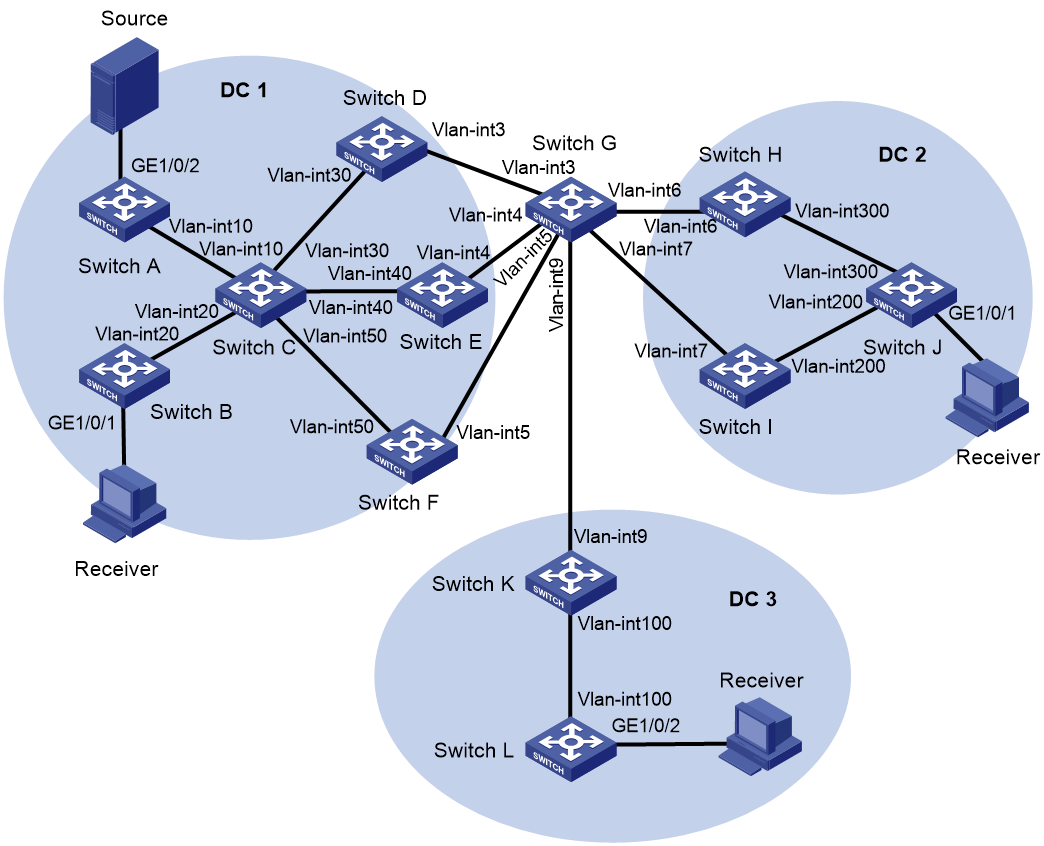
|
Device |
Interface |
IP address |
Device |
Interface |
IP address |
|
Switch A |
Loop0 |
1.1.1.1/32 |
Switch B |
Loop0 |
2.2.2.2/32 |
|
|
Loop1 |
1.1.1.1/32 |
|
Loop1 |
2.2.2.2/32 |
|
|
Vlan-int10 |
121.121.121.1/24 |
|
GE1/0/1 |
- |
|
|
GE1/0/2 |
- |
|
Vlan-int20 |
122.122.122.2/24 |
|
|
VSI-int1 |
10.0.0.1/24 |
|
VSI-int1 |
10.0.0.1/24 |
|
|
VSI-int2 |
- |
|
VSI-int2 |
- |
|
Switch C |
Loop0 |
12.12.12.12/32 |
Switch D |
Loop0 |
3.3.3.3/32 |
|
|
Vlan-int10 |
121.121.121.12/24 |
|
Loop1 |
3.3.3.3/32 |
|
|
Vlan-int20 |
122.122.122.12/24 |
|
Loop2 |
3.4.5.0/32 |
|
|
Vlan-int30 |
123.123.123.12/24 |
|
Vlan-int3 |
113.113.113.3/24 |
|
|
Vlan-int40 |
124.124.124.12/24 |
|
Vlan-int30 |
123.123.123.3/24 |
|
|
Vlan-int50 |
125.125.125.12/24 |
|
VSI-int2 |
- |
|
Switch E |
Loop0 |
4.4.4.4/32 |
Switch F |
Loop0 |
5.5.5.5/32 |
|
|
Loop1 |
4.4.4.4/32 |
|
Loop1 |
5.5.5.5/32 |
|
|
Loop2 |
3.4.5.0/32 |
|
Loop2 |
3.4.5.0/32 |
|
|
Vlan-int4 |
114.114.114.4/24 |
|
Vlan-int50 |
125.125.125.5/24 |
|
|
Vlan-int40 |
124.124.124.4/24 |
|
Vlan-int5 |
115.115.115.5/24 |
|
|
VSI-int2 |
- |
|
VSI-int2 |
- |
|
Switch G |
Loop0 |
11.11.11.11/32 |
Switch J |
Loop0 |
8.8.8.8/32 |
|
|
Vlan-int3 |
113.113.113.11/24 |
|
Loop1 |
8.8.8.8/32 |
|
|
Vlan-int4 |
114.114.114.11/24 |
|
GE1/0/1 |
- |
|
|
Vlan-int5 |
115.115.115.11/24 |
|
Vlan-int200 |
78.78.78.87/24 |
|
|
Vlan-int9 |
119.119.119.11/24 |
|
Vlan-int300 |
68.68.68.86/24 |
|
|
Vlan-int7 |
117.117.117.11/24 |
|
VSI-int1 |
10.0.0.1/24 |
|
|
Vlan-int6 |
116.116.116.11/24 |
|
VSI-int2 |
- |
|
Switch H |
Loop0 |
6.6.6.6/32 |
Switch I |
Loop0 |
7.7.7.7/32 |
|
|
Loop1 |
6.6.6.6/32 |
|
Loop1 |
7.7.7.7/32 |
|
|
Loop2 |
2.2.1.1/32 |
|
Loop2 |
2.2.1.1/32 |
|
|
Vlan-int300 |
68.68.68.68/24 |
|
Vlan-int7 |
117.117.117.7/24 |
|
|
Vlan-int6 |
116.116.116.6/24 |
|
Vlan-int200 |
78.78.78.78/24 |
|
|
VSI-int2 |
- |
|
VSI-int2 |
- |
|
Switch K |
Loop0 |
9.9.9.9/32 |
Switch L |
Loop0 |
10.10.10.10/32 |
|
|
Loop1 |
9.9.9.9/32 |
|
Loop1 |
10.10.10.10/32 |
|
|
Vlan-int100 |
109.109.109.9/24 |
|
Vlan-int100 |
109.109.109.10/24 |
|
|
Vlan-int9 |
119.119.119.9/24 |
|
GE1/0/2 |
- |
|
|
VSI-int2 |
- |
|
VSI-int1 |
10.0.0.1/24 |
|
|
|
|
|
VSI-int2 |
- |
Procedure
1. Configure IP addresses, PIM SM, and unicast routing settings:
# On the multicast source and receivers, specify 10.0.0.1 as the gateway address. (Details not shown.)
# Assign IP addresses to interfaces, as shown in Figure 16. (Details not shown.)
# Configure OSPF in each data center for the switches in a data center to reach one another. (Details not shown.)
# Enable PIM SM on the VLAN interfaces that interconnect the devices in a data center. (Details not shown.)
# Verify that PIM SM is disabled on the VLAN interfaces that interconnect the EDs. (Details not shown.)
# If you enable PIM SM on interfaces connecting EDs, you must use the pim bsr-boundary command configure each ED as a PIM-SM domain border. (Details not shown.)
2. Configure Switch A:
# Enable L2VPN, IP multicast routing, and OSPF process 1, and create VLAN 11.
<SwitchA> system-view
[SwitchA] l2vpn enable
[SwitchA] multicast routing
[SwitchA-mrib] quit
[SwitchA] pim
[SwitchA-pim] quit
[SwitchA] ospf 1
[SwitchA-ospf-1] area 0.0.0.0
[SwitchA-ospf-1-area-0.0.0.0] quit
[SwitchA] vlan 11
[SwitchA-vlan11] quit
# Enable the IGMP snooping feature.
[SwitchA] igmp-snooping
[SwitchA-igmp-snooping] quit
# Configure Loopback 0.
[SwitchA] interface loopback 0
[SwitchA-LoopBack0] ip address 1.1.1.1 32
[SwitchA-LoopBack0] ospf 1 area 0.0.0.0
[SwitchA-LoopBack0] quit
# Create an EVPN instance on VSI 1.
[SwitchA] vsi 1
[SwitchA-vsi-1] evpn encapsulation vxlan
[SwitchA-vsi-1-evpn-vxlan] route-distinguisher auto
[SwitchA-vsi-1-evpn-vxlan] vpn-target auto export-extcommunity
[SwitchA-vsi-1-evpn-vxlan] vpn-target auto import-extcommunity [SwitchA-vsi-1-evpn-vxlan] quit
# Enable IGMP snooping on VSI 1.
[SwitchA-vsi-1] igmp-snooping enable
# Create VXLAN 10.
[SwitchA-vsi-1] vxlan 10
[SwitchA-vsi-1-vxlan-10] quit
# Configure BGP to advertise BGP EVPN routes, and enable the BGP additional path receiving capability.
[SwitchA] bgp 100
[SwitchA-bgp-default] peer 12.12.12.12 as-number 100
[SwitchA-bgp-default] peer 12.12.12.12 connect-interface loopback 0
[SwitchA-bgp-default] address-family l2vpn evpn
[SwitchA-bgp-default-evpn] peer 12.12.12.12 enable
[SwitchA-bgp-default-evpn] peer 12.12.12.12 additional-paths receive
[SwitchA-bgp-default-evpn] quit
[SwitchA-bgp-default] quit
# On server-facing interface GigabitEthernet 1/0/2, create Ethernet service instance 11 to match VLAN 11.
[SwitchA] interface gigabitethernet 1/0/2
[SwitchA-GigabitEthernet1/0/2] port link-mode bridge
[SwitchA-GigabitEthernet1/0/2] port link-type trunk
[SwitchA-GigabitEthernet1/0/2] port trunk permit vlan 1 11
[SwitchA-GigabitEthernet1/0/2] service-instance 11
[SwitchA-GigabitEthernet1/0/2-srv11] encapsulation s-vid 11
# Map Ethernet service instance 11 to VSI 1.
[SwitchA-GigabitEthernet1/0/2-srv11] xconnect vsi 1
[SwitchA-GigabitEthernet1/0/2-srv11] quit
[SwitchA-GigabitEthernet1/0/2] quit
# Configure RD and route target settings for VPN instance a.
[SwitchA] ip vpn-instance a
[SwitchA-vpn-instance-a] route-distinguisher 1:1
[SwitchA-vpn-instance-a] vpn-target 10:10 import-extcommunity
[SwitchA-vpn-instance-a] vpn-target 10:10 export-extcommunity
[SwitchA-vpn-instance-a] quit
# Configure VSI-interface 1.
[SwitchA] interface vsi-interface 1
[SwitchA-Vsi-interface1] ip binding vpn-instance a
[SwitchA-Vsi-interface1] ip address 10.0.0.1 255.255.255.0
[SwitchA-Vsi-interface1] pim sm
[SwitchA-Vsi-interface1] igmp enable
[SwitchA-Vsi-interface1] mac-address 0001-0001-0001
[SwitchA-Vsi-interface1] distributed-gateway local
[SwitchA-Vsi-interface1] quit
# Create VSI-interface 2, associate the VSI interface with VPN instance a, and configure the L3 VXLAN ID as 1000 for the VPN instance.
[SwitchA] interface vsi-interface 2
[SwitchA-Vsi-interface2] ip binding vpn-instance a
[SwitchA-Vsi-interface2] l3-vni 1000
[SwitchA-Vsi-interface2] pim sm
[SwitchA-Vsi-interface2] quit
# Enable IP multicast routing for VPN instance a.
[SwitchA] multicast routing vpn-instance a
[SwitchA-mrib-a] quit
# Create an MDT-based MVXLAN for VPN instance a and enter MVXLAN IPv4 address family view. Configure the default group, MVXLAN source interface, and data group range settings. Enable advertising active multicast sources through S-PMSI routes.
[SwitchA] multicast-vpn vxlan vpn-instance a mode mdt
[SwitchA-mvxlan-a] address-family ipv4
[SwitchA-mvxlan-a-ipv4] default-group 236.0.0.0
[SwitchA-mvxlan-a-ipv4] source loopback 0
[SwitchA-mvxlan-a-ipv4] data-group 239.0.0.0 24
[SwitchA-mvxlan-a-ipv4] s-pmsi advertise source-active
[SwitchA-mvxlan-a-ipv4] quit
[SwitchA-mvxlan-a] quit
# Configure Loopback 1.
[SwitchA] interface loopback 1
[SwitchA-LoopBack1] ip binding vpn-instance a
[SwitchA-LoopBack1] ip address 1.1.1.1 32
[SwitchA-LoopBack1] pim sm
[SwitchA-LoopBack1] quit
# Enter VPN instance PIM view, and configure Loopback 1 as a candidate-BSR and candidate-RP in VPN instance a.
[SwitchA] pim vpn-instance a
[SwitchA-pim-a] c-bsr 1.1.1.1
[SwitchA-pim-a] c-rp 1.1.1.1
[SwitchA-pim-a] quit
# Specify VSI-interface 1 as the gateway interface for VSI 1.
[SwitchA] vsi 1
[SwitchA-vsi-1] gateway vsi-interface 1
[SwitchA-vsi-1] quit
3. Configure Switch B:
# Enable L2VPN, IP multicast routing, and OSPF process 1, and create VLAN 22.
<SwitchB> system-view
[SwitchB] l2vpn enable
[SwitchB] multicast routing
[SwitchB-mrib] quit
[SwitchB] pim
[SwitchB-pim] quit
[SwitchB] ospf 1
[SwitchB-ospf-1] area 0.0.0.0
[SwitchB-ospf-1-area-0.0.0.0] quit
[SwitchB-ospf-1] quit
[SwitchB] vlan 22
[SwitchB-vlan22] quit
# Enable the IGMP snooping feature.
[SwitchB] igmp-snooping
[SwitchB-igmp-snooping] quit
# Configure Loopback 0.
[SwitchB] interface loopback 0
[SwitchB-LoopBack0] ip address 2.2.2.2 32
[SwitchB-LoopBack0] ospf 1 area 0.0.0.0
[SwitchB-LoopBack0] quit
# Create an EVPN instance on VSI 1.
[SwitchB] vsi 1
[SwitchB-vsi-1] evpn encapsulation vxlan
[SwitchB-vsi-1-evpn-vxlan] route-distinguisher auto
[SwitchB-vsi-1-evpn-vxlan] vpn-target auto export-extcommunity
[SwitchB-vsi-1-evpn-vxlan] vpn-target auto import-extcommunity [SwitchB-vsi-1-evpn-vxlan] quit
# Enable IGMP snooping on VSI 1.
[SwitchB-vsi-1] igmp-snooping enable
# Create VXLAN 10.
[SwitchB-vsi-1] vxlan 10
[SwitchB-vsi-1-vxlan-10] quit
# Configure BGP to advertise BGP EVPN routes, and enable the BGP additional path receiving capability.
[SwitchB] bgp 100
[SwitchB-bgp-default] peer 12.12.12.12 as-number 100
[SwitchB-bgp-default] peer 12.12.12.12 connect-interface loopback 0
[SwitchB-bgp-default] address-family l2vpn evpn
[SwitchB-bgp-default-evpn] peer 12.12.12.12 enable
[SwitchB-bgp-default-evpn] peer 12.12.12.12 additional-paths receive
[SwitchB-bgp-default-evpn] quit
[SwitchB-bgp-default] quit
# On server-facing interface GigabitEthernet 1/0/1, create Ethernet service instance 22 to match VLAN 22.
[SwitchB] interface gigabitethernet 1/0/1
[SwitchB-GigabitEthernet1/0/1] port link-mode bridge
[SwitchB-GigabitEthernet1/0/1] port link-type trunk
[SwitchB-GigabitEthernet1/0/1] port trunk permit vlan 1 22
[SwitchB-GigabitEthernet1/0/1] service-instance 22
[SwitchB-GigabitEthernet1/0/1-srv22] encapsulation s-vid 22
# Map Ethernet service instance 22 to VSI 1.
[SwitchB-GigabitEthernet1/0/1-srv22] xconnect vsi 1
[SwitchB-GigabitEthernet1/0/1-srv22] quit
[SwitchB-GigabitEthernet1/0/1] quit
# Configure RD and route target settings for VPN instance a.
[SwitchB] ip vpn-instance a
[SwitchB-vpn-instance-a] route-distinguisher 2:2
[SwitchB-vpn-instance-a] vpn-target 10:10 import-extcommunity
[SwitchB-vpn-instance-a] vpn-target 10:10 export-extcommunity
[SwitchB-vpn-instance-a] quit
# Configure VSI-interface 1.
[SwitchB] interface vsi-interface 1
[SwitchB-Vsi-interface1] ip binding vpn-instance a
[SwitchB-Vsi-interface1] ip address 10.0.0.1 255.255.255.0
[SwitchB-Vsi-interface1] pim sm
[SwitchB-Vsi-interface1] igmp enable
[SwitchB-Vsi-interface1] mac-address 0001-0001-0001
[SwitchB-Vsi-interface1] distributed-gateway local
[SwitchB-Vsi-interface1] quit
# Create VSI-interface 2, associate the VSI interface with VPN instance a, and configure the L3 VXLAN ID as 1000 for the VPN instance.
[SwitchB] interface vsi-interface 2
[SwitchB-Vsi-interface2] ip binding vpn-instance a
[SwitchB-Vsi-interface2] l3-vni 1000
[SwitchB-Vsi-interface2] pim sm
[SwitchB-Vsi-interface2] quit
# Enable IP multicast routing for VPN instance a.
[SwitchB] multicast routing vpn-instance a
[SwitchB-mrib-a] quit
# Create an MDT-based MVXLAN for VPN instance a and enter MVXLAN IPv4 address family view. Configure the default group, MVXLAN source interface, and data group range settings. Enable advertising active multicast sources through S-PMSI routes.
[SwitchB] multicast-vpn vxlan vpn-instance a mode mdt
[SwitchB-mvxlan-a] address-family ipv4
[SwitchB-mvxlan-a-ipv4] default-group 236.0.0.0
[SwitchB-mvxlan-a-ipv4] source loopback 0
[SwitchB-mvxlan-a-ipv4] data-group 239.0.0.0 24
[SwitchB-mvxlan-a-ipv4] s-pmsi advertise source-active
[SwitchB-mvxlan-a-ipv4] quit
[SwitchB-mvxlan-a] quit
# Configure Loopback 1.
[SwitchB] interface loopback 1
[SwitchB-LoopBack1] ip binding vpn-instance a
[SwitchB-LoopBack1] ip address 2.2.2.2 32
[SwitchB-LoopBack1] pim sm
[SwitchB-LoopBack1] quit
# Enter VPN instance PIM view, and configure Loopback 1 as a candidate-BSR and candidate-RP in VPN instance a.
[SwitchB] pim vpn-instance a
[SwitchB-pim-a] c-bsr 2.2.2.2
[SwitchB-pim-a] c-rp 2.2.2.2
[SwitchB-pim-a] quit
# Specify VSI-interface 1 as the gateway interface for VSI 1.
[SwitchB] vsi 1
[SwitchB-vsi-1] gateway vsi-interface 1
[SwitchB-vsi-1] quit
4. Configure Switch C:
# Enable IP multicast routing and OSPF process 1.
<SwitchC> system-view
[SwitchC] multicast routing
[SwitchC-mrib] quit
[SwitchC] pim
[SwitchC-pim] quit
[SwitchC] ospf 1
[SwitchC-ospf-1] area 0.0.0.0
[SwitchC-ospf-1-area-0.0.0.0] quit
[SwitchC-ospf-1] quit
# Configure Loopback 0.
[SwitchC] interface loopback 0
[SwitchC-LoopBack0] ip address 12.12.12.12 32
[SwitchC-LoopBack0] ospf 1 area 0.0.0.0
[SwitchC-LoopBack0] quit
# Configure Switch C as an RR to reflect BGP EVPN routes between switches. Enable the BGP additional path sending capability to Switch A and Switch B, and set the maximum number of Add-Path optimal routes that can be advertised. The maximum number of Add-Path optimal routes cannot be smaller than the number of peer EDs.
[SwitchC] bgp 100
[SwitchC-bgp-default] group ED internal
[SwitchC-bgp-default] peer ED connect-interface loopback 0
[SwitchC-bgp-default] group VTEP internal
[SwitchC-bgp-default] peer VTEP connect-interface loopback 0
[SwitchC-bgp-default] peer 1.1.1.1 group VTEP
[SwitchC-bgp-default] peer 2.2.2.2 group VTEP
[SwitchC-bgp-default] peer 3.3.3.3 group ED
[SwitchC-bgp-default] peer 4.4.4.4 group ED
[SwitchC-bgp-default] peer 5.5.5.5 group ED
[SwitchC-bgp-default] address-family l2vpn evpn
[SwitchC-bgp-default-evpn] undo policy vpn-target
[SwitchC-bgp-default-evpn] additional-paths select-best 3
[SwitchC-bgp-default-evpn] peer ED enable
[SwitchC-bgp-default-evpn] peer ED reflect-client
[SwitchC-bgp-default-evpn] peer VTEP enable
[SwitchC-bgp-default-evpn] peer VTEP reflect-client
[SwitchC-bgp-default-evpn] peer VTEP additional-paths send
[SwitchC-bgp-default-evpn] peer VTEP advertise additional-paths best 3
[SwitchC-bgp-default-evpn] quit
[SwitchC-bgp-default] quit
5. Configure Switch D:
# Enable L2VPN, IP multicast routing, OSPF process 1, and RIP process 1.
<SwitchD> system-view
[SwitchD] l2vpn enable
[SwitchD] multicast routing
[SwitchD-mrib] quit
[SwitchD] pim
[SwitchD-pim] quit
[SwitchD] ospf 1
[SwitchD-ospf-1] area 0.0.0.0
[SwitchD-ospf-1-area-0.0.0.0] quit
[SwitchD-ospf-1] quit
[SwitchD] rip 1
[SwitchD-rip-1] network 3.0.0.0
[SwitchD-rip-1] network 113.0.0.0
[SwitchD-rip-1] quit
# Enable the IGMP snooping feature.
[SwitchD] igmp-snooping
[SwitchD-igmp-snooping] quit
# Configure Loopback 0.
[SwitchD] interface loopback 0
[SwitchD-LoopBack0] ip address 3.3.3.3 32
[SwitchD-LoopBack0] rip 1 enable
[SwitchD-LoopBack0] ospf 1 area 0.0.0.0
[SwitchD-LoopBack0] quit
# Configure RIP and enable DCI multicast on the interface connected to a peer ED.
[SwitchD] interface vlan-interface 3
[SwitchD-Vlan-interface3] rip 1 enable
[SwitchD-Vlan-interface3] dci enable
[SwitchD-Vlan-interface3] quit
# Specify virtual ED address 3.4.5.0.
[SwitchD] evpn edge group 3.4.5.0
# Specify peer EDs for the local ED.
[SwitchD] multicast-vpn vxlan edge remote 4.4.4.4
[SwitchD] multicast-vpn vxlan edge remote 5.5.5.5
# Configure RD and route target settings for VPN instance a.
[SwitchD] ip vpn-instance a
[SwitchD-vpn-instance-a] route-distinguisher 3:3
[SwitchD-vpn-instance-a] vpn-target 10:10 200:200 300:300 import-extcommunity
[SwitchD-vpn-instance-a] vpn-target 10:10 export-extcommunity
[SwitchD-vpn-instance-a] quit
# Configure RD and route target settings for VPN instance b.
[SwitchD] ip vpn-instance b
[SwitchD-vpn-instance-b] route-distinguisher 3:33
[SwitchD-vpn-instance-b] vpn-target 10:10 200:200 300:300 import-extcommunity
[SwitchD-vpn-instance-b] vpn-target 10:10 export-extcommunity
[SwitchD-vpn-instance-b] quit
# Configure Loopback 1.
[SwitchD] interface loopback 1
[SwitchD-LoopBack1] ip binding vpn-instance a
[SwitchD-LoopBack1] ip address 3.3.3.3 32
[SwitchD-LoopBack1] pim sm
[SwitchD-LoopBack1] quit
# Configure Loopback 2.
[SwitchD] interface loopback 2
[SwitchD-LoopBack2] ip address 3.4.5.0 32
[SwitchD-LoopBack2] rip 1 enable
[SwitchD-LoopBack2] ospf 1 area 0.0.0.0
[SwitchD-LoopBack2] quit
# Enter VPN instance PIM view, and configure Loopback 1 as a candidate-BSR and candidate-RP in VPN instance a.
[SwitchD] pim vpn-instance a
[SwitchD-pim-a] c-bsr 3.3.3.3
[SwitchD-pim-a] c-rp 3.3.3.3
[SwitchD-pim-a] quit
# Create VSI-interface 2, associate the VSI interface with VPN instance a, and configure the L3 VXLAN ID as 1000 for the VPN instance.
[SwitchD] interface vsi-interface 2
[SwitchD-Vsi-interface2] ip binding vpn-instance a
[SwitchD-Vsi-interface2] l3-vni 1000
[SwitchD-Vsi-interface2] pim sm
[SwitchD-Vsi-interface2] quit
# Create VSI-interface 3, associate the VSI interface with VPN instance b, and configure the L3 VXLAN ID as 4000 for the VPN instance.
[SwitchD] interface vsi-interface 3
[SwitchD-Vsi-interface3] ip binding vpn-instance b
[SwitchD-Vsi-interface3] l3-vni 4000
[SwitchD-Vsi-interface3] pim sm
[SwitchD-Vsi-interface3] quit
# Enable IP multicast routing for VPN instance a.
[SwitchD] multicast routing vpn-instance a
[SwitchD-mrib-a] quit
# Enable IP multicast routing for VPN instance b.
[SwitchD] multicast routing vpn-instance b
[SwitchD-mrib-b] quit
[SwitchD] pim vpn-instance b
[SwitchD-pim-b] quit
# Create an MDT-based MVXLAN for VPN instance a and enter MVXLAN IPv4 address family view. Configure the default group, MVXLAN source interface, and data group range settings. Enable DCI multicast.
[SwitchD] multicast-vpn vxlan vpn-instance a mode mdt
[SwitchD-mvxlan-a] address-family ipv4
[SwitchD-mvxlan-a-ipv4] default-group 236.0.0.0
[SwitchD-mvxlan-a-ipv4] source loopback 0
[SwitchD-mvxlan-a-ipv4] data-group 239.0.0.0 24
[SwitchD-mvxlan-a-ipv4] dci enable
[SwitchD-mvxlan-a-ipv4] quit
[SwitchD-mvxlan-a] quit
# Configure a routing policy. Configure Switch D to not forward the SMET and S-PMSI routes received from Switch H and Switch I to Switch K. Configure Switch D to not forward the SMET and S-PMSI routes received from Switch K to Switch H and Switch I.
[SwitchD] ip prefix-list 1 index 10 permit 0.0.0.0 0 less-equal 32
[SwitchD] ip prefix-list 2 index 10 permit 6.6.6.6 32
[SwitchD] ip prefix-list 2 index 20 permit 7.7.7.7 32
[SwitchD] ip prefix-list 3 index 10 permit 9.9.9.9 32
[SwitchD] route-policy dc2 deny node 0
[SwitchD-route-policy-dc2-0] if-match ip route-source prefix-list 3
[SwitchD-route-policy-dc2-0] if-match route-type bgp-evpn-smet bgp-evpn-s-pmsi
[SwitchD-route-policy-dc2-0] route-policy dc2 permit node 1
[SwitchD-route-policy-dc2-1] if-match ip route-source prefix-list 1
[SwitchD-route-policy-dc2-1] route-policy dc3 deny node 0
[SwitchD-route-policy-dc3-0] if-match ip route-source prefix-list 2
[SwitchD-route-policy-dc3-0] if-match route-type bgp-evpn-smet bgp-evpn-s-pmsi
[SwitchD-route-policy-dc3-0] route-policy dc3 permit node 1
[SwitchD-route-policy-dc3-1] if-match ip route-source prefix-list 1
[SwitchD-route-policy-dc3-1] quit
# Configure a routing policy to change the next hop of the S-PMSI routes sent from Switch D to Switch C to 3.3.3.3.
[SwitchD] route-policy rt_spmsi permit node 0
[SwitchD-route-policy-rt_spmsi-0] if-match route-type bgp-evpn-s-pmsi
[SwitchD-route-policy-rt_spmsi-0] apply ip-address next-hop 3.3.3.3
[SwitchD-route-policy-rt_spmsi-0] route-policy rt_spmsi permit node 1
[SwitchD-route-policy-rt_spmsi-1] quit
# Enable BGP to advertise BGP EVPN routes, and configure the device to modify the information in received BGP EVPN routes.
[SwitchD] bgp 100
[SwitchD-bgp-default] group ED2 external
[SwitchD-bgp-default] peer ED2 as-number 200
[SwitchD-bgp-default] peer ED2 connect-interface loopback 0
[SwitchD-bgp-default] peer ED2 ebgp-max-hop 64
[SwitchD-bgp-default] peer 6.6.6.6 group ED2
[SwitchD-bgp-default] peer 7.7.7.7 group ED2
[SwitchD-bgp-default] peer 9.9.9.9 as-number 300
[SwitchD-bgp-default] peer 9.9.9.9 connect-interface loopback 0
[SwitchD-bgp-default] peer 9.9.9.9 ebgp-max-hop 64
[SwitchD-bgp-default] peer 12.12.12.12 as-number 100
[SwitchD-bgp-default] peer 12.12.12.12 connect-interface loopback 0
[SwitchD-bgp-default] address-family l2vpn evpn
[SwitchD-bgp-default-evpn] peer ED2 enable
[SwitchD-bgp-default-evpn] peer ED2 route-policy dc2 export
[SwitchD-bgp-default-evpn] peer ED2 router-mac-local
[SwitchD-bgp-default-evpn] peer ED2 re-originated replace-rt
[SwitchD-bgp-default-evpn] peer ED2 imet replace-rt
[SwitchD-bgp-default-evpn] peer ED2 mac-ip replace-rt
[SwitchD-bgp-default-evpn] peer ED2 smet replace-rt
[SwitchD-bgp-default-evpn] peer ED2 s-pmsi replace-rt
[SwitchD-bgp-default-evpn] peer 9.9.9.9 enable
[SwitchD-bgp-default-evpn] peer 9.9.9.9 route-policy dc3 export
[SwitchD-bgp-default-evpn] peer 9.9.9.9 router-mac-local
[SwitchD-bgp-default-evpn] peer 9.9.9.9 re-originated replace-rt
[SwitchD-bgp-default-evpn] peer 9.9.9.9 re-originated mac-ip replace-rt
[SwitchD-bgp-default-evpn] peer 9.9.9.9 re-originated imet replace-rt
[SwitchD-bgp-default-evpn] peer 9.9.9.9 re-originated smet replace-rt
[SwitchD-bgp-default-evpn] peer 9.9.9.9 re-originated s-pmsi replace-rt
[SwitchD-bgp-default-evpn] peer 12.12.12.12 enable
[SwitchD-bgp-default-evpn] peer 12.12.12.12 route-policy rt_spmsi export
[SwitchD-bgp-default-evpn] peer 12.12.12.12 re-originated replace-rt
[SwitchD-bgp-default-evpn] peer 12.12.12.12 re-originated mac-ip replace-rt
[SwitchD-bgp-default-evpn] peer 12.12.12.12 re-originated imet replace-rt
[SwitchD-bgp-default-evpn] peer 12.12.12.12 re-originated smet replace-rt
[SwitchD-bgp-default-evpn] peer 12.12.12.12 re-originated s-pmsi replace-rt
[SwitchD-bgp-default-evpn] quit
[SwitchD-bgp-default] quit
6. Configure Switch E:
# Enable L2VPN, IP multicast routing, OSPF process 1, and RIP process 1.
<SwitchE> system-view
[SwitchE] l2vpn enable
[SwitchE] multicast routing
[SwitchE-mrib] quit
[SwitchE] pim
[SwitchE-pim] quit
[SwitchE] ospf 1
[SwitchE-ospf-1] area 0.0.0.0
[SwitchE-ospf-1-area-0.0.0.0] quit
[SwitchE] rip 1
[SwitchE-rip-1] network 4.0.0.0
[SwitchE-rip-1] network 114.0.0.0
[SwitchE-rip-1] quit
# Enable the IGMP snooping feature.
[SwitchE] igmp-snooping
[SwitchE-igmp-snooping] quit
# Configure Loopback 0.
[SwitchE] interface loopback 0
[SwitchE-LoopBack0] ip address 4.4.4.4 32
[SwitchE-LoopBack0] rip 1 enable
[SwitchE-LoopBack0] ospf 1 area 0.0.0.0
[SwitchE-LoopBack0] quit
# Configure RIP and enable DCI multicast on the interface connected to a peer ED.
[SwitchE] interface vlan-interface 4
[SwitchE-Vlan-interface4] rip 1 enable
[SwitchE-Vlan-interface4] dci enable
[SwitchE-Vlan-interface4] quit
# Specify virtual ED address 3.4.5.0.
[SwitchE] evpn edge group 3.4.5.0
# Configure RD and route target settings for VPN instance a.
[SwitchE] ip vpn-instance a
[SwitchE-vpn-instance-a] route-distinguisher 4:4
[SwitchE-vpn-instance-a] vpn-target 10:10 200:200 300:300 import-extcommunity
[SwitchE-vpn-instance-a] vpn-target 10:10 export-extcommunity
[SwitchE-vpn-instance-a] quit
# Configure RD and route target settings for VPN instance b.
[SwitchE] ip vpn-instance b
[SwitchE-vpn-instance-b] route-distinguisher 4:44
[SwitchE-vpn-instance-b] vpn-target 10:10 200:200 300:300 import-extcommunity
[SwitchE-vpn-instance-b] vpn-target 100:100 export-extcommunity
[SwitchE-vpn-instance-b] quit
# Configure Loopback 1.
[SwitchE] interface loopback 1
[SwitchE-LoopBack1] ip binding vpn-instance a
[SwitchE-LoopBack1] ip address 4.4.4.4 32
[SwitchE-LoopBack1] pim sm
[SwitchE-LoopBack1] quit
# Configure Loopback 2.
[SwitchE] interface loopback 2
[SwitchE-LoopBack2] ip address 3.4.5.0 32
[SwitchE-LoopBack2] rip 1 enable
[SwitchE-LoopBack2] ospf 1 area 0.0.0.0
[SwitchE-LoopBack2] quit
# Create VSI-interface 2, associate the VSI interface with VPN instance a, and configure the L3 VXLAN ID as 1000 for the VPN instance.
[SwitchE] interface vsi-interface 2
[SwitchE-Vsi-interface2] ip binding vpn-instance a
[SwitchE-Vsi-interface2] l3-vni 1000
[SwitchE-Vsi-interface2] pim sm
[SwitchE-Vsi-interface2] quit
# Create VSI-interface 3, associate the VSI interface with VPN instance b, and configure the L3 VXLAN ID as 4000 for the VPN instance.
[SwitchE] interface vsi-interface 3
[SwitchE-Vsi-interface3] ip binding vpn-instance b
[SwitchE-Vsi-interface3] l3-vni 4000
[SwitchE-Vsi-interface3] pim sm
[SwitchE-Vsi-interface3] quit
# Enable IP multicast routing for VPN instance a.
[SwitchE] multicast routing vpn-instance a
[SwitchE-mrib-a] quit
# Enter VPN instance PIM view, and configure Loopback 1 as a candidate-BSR and candidate-RP in VPN instance a.
[SwitchE] pim vpn-instance a
[SwitchE-pim-a] c-bsr 4.4.4.4
[SwitchE-pim-a] c-rp 4.4.4.4
[SwitchE-pim-a] quit
# Enable IP multicast routing for VPN instance b.
[SwitchE] multicast routing vpn-instance b
[SwitchE-mrib-b] quit
[SwitchE] pim vpn-instance b
[SwitchE-pim-b] quit
# Specify peer EDs for the local ED.
[SwitchE] multicast-vpn vxlan edge remote 3.3.3.3
[SwitchE] multicast-vpn vxlan edge remote 5.5.5.5
# Create an MDT-based MVXLAN for VPN instance a and enter MVXLAN IPv4 address family view. Configure the default group, MVXLAN source interface, and data group range settings. Enable DCI multicast.
[SwitchE] multicast-vpn vxlan vpn-instance a mode mdt
[SwitchE-mvxlan-a] address-family ipv4
[SwitchE-mvxlan-a-ipv4] default-group 236.0.0.0
[SwitchE-mvxlan-a-ipv4] source loopback 0
[SwitchE-mvxlan-a-ipv4] data-group 239.0.0.0 24
[SwitchE-mvxlan-a-ipv4] dci enable
[SwitchE-mvxlan-a-ipv4] quit
[SwitchE-mvxlan-a] quit
# Configure a routing policy. Configure Switch E to not forward the SMET and S-PMSI routes received from Switch H and Switch I to Switch K. Configure Switch E to not forward the SMET and S-PMSI routes received from Switch K to Switch H and Switch I.
[SwitchE] ip prefix-list 1 index 10 permit 0.0.0.0 0 less-equal 32
[SwitchE] ip prefix-list 2 index 10 permit 6.6.6.6 32
[SwitchE] ip prefix-list 2 index 20 permit 7.7.7.7 32
[SwitchE] ip prefix-list 3 index 10 permit 9.9.9.9 32
[SwitchE] route-policy dc2 deny node 0
[SwitchE-route-policy-dc2-0] if-match ip route-source prefix-list 3
[SwitchE-route-policy-dc2-0] if-match route-type bgp-evpn-smet bgp-evpn-s-pmsi
[SwitchE-route-policy-dc2-0] route-policy dc2 permit node 1
[SwitchE-route-policy-dc2-1] if-match ip route-source prefix-list 1
[SwitchE-route-policy-dc2-1] route-policy dc3 deny node 0
[SwitchE-route-policy-dc3-0] if-match ip route-source prefix-list 2
[SwitchE-route-policy-dc3-0] if-match route-type bgp-evpn-smet bgp-evpn-s-pmsi
[SwitchE-route-policy-dc3-0] route-policy dc3 permit node 1
[SwitchE-route-policy-dc3-1] if-match ip route-source prefix-list 1
[SwitchE-route-policy-dc3-1] quit
# Configure a routing policy to change the next hop of the S-PMSI routes sent from Switch E to Switch C to 4.4.4.4.
[SwitchE] route-policy rt_spmsi permit node 0
[SwitchE-route-policy-rt_spmsi-0] if-match route-type bgp-evpn-s-pmsi
[SwitchE-route-policy-rt_spmsi-0] apply ip-address next-hop 4.4.4.4
[SwitchE-route-policy-rt_spmsi-0] route-policy rt_spmsi permit node 1
[SwitchE-route-policy-rt_spmsi-1] quit
# Enable BGP to advertise BGP EVPN routes, and configure the device to modify the information in received BGP EVPN routes.
[SwitchE] bgp 100
[SwitchE-bgp-default] group ED2 external
[SwitchE-bgp-default] peer ED2 as-number 200
[SwitchE-bgp-default] peer ED2 connect-interface loopback 0
[SwitchE-bgp-default] peer ED2 ebgp-max-hop 64
[SwitchE-bgp-default] peer 6.6.6.6 group ED2
[SwitchE-bgp-default] peer 7.7.7.7 group ED2
[SwitchE-bgp-default] peer 9.9.9.9 as-number 300
[SwitchE-bgp-default] peer 9.9.9.9 connect-interface loopback 0
[SwitchE-bgp-default] peer 9.9.9.9 ebgp-max-hop 64
[SwitchE-bgp-default] peer 12.12.12.12 as-number 100
[SwitchE-bgp-default] peer 12.12.12.12 connect-interface loopback 0
[SwitchE-bgp-default] address-family l2vpn evpn
[SwitchE-bgp-default-evpn] undo policy vpn-target
[SwitchE-bgp-default-evpn] peer ED2 enable
[SwitchE-bgp-default-evpn] peer ED2 route-policy dc2 export
[SwitchE-bgp-default-evpn] peer ED2 router-mac-local
[SwitchE-bgp-default-evpn] peer ED2 re-originated replace-rt
[SwitchE-bgp-default-evpn] peer ED2 imet replace-rt
[SwitchE-bgp-default-evpn] peer ED2 mac-ip replace-rt
[SwitchE-bgp-default-evpn] peer ED2 smet replace-rt
[SwitchE-bgp-default-evpn] peer ED2 s-pmsi replace-rt
[SwitchE-bgp-default-evpn] peer 9.9.9.9 enable
[SwitchE-bgp-default-evpn] peer 9.9.9.9 route-policy dc3 export
[SwitchE-bgp-default-evpn] peer 9.9.9.9 router-mac-local
[SwitchE-bgp-default-evpn] peer 9.9.9.9 re-originated replace-rt
[SwitchE-bgp-default-evpn] peer 9.9.9.9 re-originated mac-ip replace-rt
[SwitchE-bgp-default-evpn] peer 9.9.9.9 re-originated imet replace-rt
[SwitchE-bgp-default-evpn] peer 9.9.9.9 re-originated smet replace-rt
[SwitchE-bgp-default-evpn] peer 9.9.9.9 re-originated s-pmsi replace-rt
[SwitchE-bgp-default-evpn] peer 12.12.12.12 enable
[SwitchE-bgp-default-evpn] peer 12.12.12.12 route-policy rt_spmsi export
[SwitchE-bgp-default-evpn] peer 12.12.12.12 re-originated replace-rt
[SwitchE-bgp-default-evpn] peer 12.12.12.12 re-originated mac-ip replace-rt
[SwitchE-bgp-default-evpn] peer 12.12.12.12 re-originated imet replace-rt
[SwitchE-bgp-default-evpn] peer 12.12.12.12 re-originated smet replace-rt
[SwitchE-bgp-default-evpn] peer 12.12.12.12 re-originated s-pmsi replace-rt
[SwitchE-bgp-default-evpn] quit
[SwitchE-bgp-default] quit
7. Configure Switch F:
# Enable L2VPN, IP multicast routing, OSPF process 1, and RIP process 1.
<SwitchF> system-view
[SwitchF] l2vpn enable
[SwitchF] multicast routing
[SwitchF-mrib] quit
[SwitchF] pim
[SwitchF-pim] quit
[SwitchF] ospf 1
[SwitchF-ospf-1] area 0.0.0.0
[SwitchF-ospf-1-area-0.0.0.0] quit
[SwitchF] rip 1
[SwitchF-rip-1] network 5.0.0.0
[SwitchF-rip-1] network 115.0.0.0
[SwitchF-rip-1] quit
# Enable the IGMP snooping feature.
[SwitchF] igmp-snooping
[SwitchF-igmp-snooping] quit
# Configure Loopback 0.
[SwitchF] interface loopback 0
[SwitchF-LoopBack0] ip address 5.5.5.5 32
[SwitchF-LoopBack0] rip 1 enable
[SwitchF-LoopBack0] ospf 1 area 0.0.0.0
[SwitchF-LoopBack0] quit
# Configure RIP and enable DCI multicast on the interface connected to a peer ED
[SwitchF] interface vlan-interface 5
[SwitchF-Vlan-interface5] rip 1 enable
[SwitchF-Vlan-interface5] dci enable
[SwitchF-Vlan-interface5] quit
# Configure RD and route target settings for VPN instance a.
[SwitchF] ip vpn-instance a
[SwitchF-vpn-instance-a] route-distinguisher 5:5
[SwitchF-vpn-instance-a] vpn-target 10:10 200:200 300:300 import-extcommunity
[SwitchF-vpn-instance-a] vpn-target 10:10 export-extcommunity
[SwitchF-vpn-instance-a] quit
# Configure RD and route target settings for VPN instance b.
[SwitchF] ip vpn-instance b
[SwitchF-vpn-instance-b] route-distinguisher 5:55
[SwitchF-vpn-instance-b] vpn-target 10:10 200:200 300:300 import-extcommunity
[SwitchF-vpn-instance-b] vpn-target 100:100 export-extcommunity
[SwitchF-vpn-instance-b] quit
# Configure Loopback 1.
[SwitchF] interface loopback 1
[SwitchF-LoopBack1] ip binding vpn-instance a
[SwitchF-LoopBack1] ip address 5.5.5.5 32
[SwitchF-LoopBack1] pim sm
[SwitchF-LoopBack1] quit
# Configure Loopback 2.
[SwitchF] interface loopback 2
[SwitchF-LoopBack2] ip address 3.4.5.0 32
[SwitchF-LoopBack2] rip 1 enable
[SwitchF-LoopBack2] ospf 1 area 0.0.0.0
[SwitchF-LoopBack2] quit
# Create VSI-interface 2, associate the VSI interface with VPN instance a, and configure the L3 VXLAN ID as 1000 for the VPN instance.
[SwitchF] interface vsi-interface 2
[SwitchF-Vsi-interface2] ip binding vpn-instance a
[SwitchF-Vsi-interface2] l3-vni 1000
[SwitchF-Vsi-interface2] pim sm
[SwitchF-Vsi-interface2] quit
# Create VSI-interface 3, associate the VSI interface with VPN instance b, and configure the L3 VXLAN ID as 4000 for the VPN instance.
[SwitchF] interface vsi-interface 3
[SwitchF-Vsi-interface2] ip binding vpn-instance b
[SwitchF-Vsi-interface2] l3-vni 4000
[SwitchF-Vsi-interface2] pim sm
[SwitchF-Vsi-interface2] quit
# Enable IP multicast routing for VPN instance a.
[SwitchF] multicast routing vpn-instance a
[SwitchF-mrib-a] quit
# Enter VPN instance PIM view, and configure Loopback 1 as a candidate-BSR and candidate-RP in VPN instance a.
[SwitchF] pim vpn-instance a
[SwitchF-pim-a] c-bsr 5.5.5.5
[SwitchF-pim-a] c-rp 5.5.5.5
[SwitchF-pim-a] quit
# Enable IP multicast routing for VPN instance b.
[SwitchF] multicast routing vpn-instance b
[SwitchF-mrib-b] quit
[SwitchF] pim vpn-instance b
[SwitchF-pim-b] quit
# Specify virtual ED address 3.4.5.0.
[SwitchF] evpn edge group 3.4.5.0
# Specify peer EDs for the local ED.
[SwitchF] multicast-vpn vxlan edge remote 3.3.3.3
[SwitchF] multicast-vpn vxlan edge remote 4.4.4.4
# Create an MDT-based MVXLAN for VPN instance a and enter MVXLAN IPv4 address family view. Configure the default group, MVXLAN source interface, and data group range settings. Enable DCI multicast.
[SwitchF] multicast-vpn vxlan vpn-instance a mode mdt
[SwitchF-mvxlan-a] address-family ipv4
[SwitchF-mvxlan-a-ipv4] default-group 236.0.0.0
[SwitchF-mvxlan-a-ipv4] source loopback 0
[SwitchF-mvxlan-a-ipv4] data-group 239.0.0.0 24
[SwitchF-mvxlan-a-ipv4] dci enable
[SwitchF-mvxlan-a-ipv4] quit
[SwitchF-mvxlan-a] quit
# Configure a routing policy. Configure Switch F to not forward the SMET and S-PMSI routes received from Switch H and Switch I to Switch K. Configure Switch F to not forward the SMET and S-PMSI routes received from Switch K to Switch H and Switch I.
[SwitchF] ip prefix-list 1 index 10 permit 0.0.0.0 0 less-equal 32
[SwitchF] ip prefix-list 2 index 10 permit 6.6.6.6 32
[SwitchF] ip prefix-list 2 index 20 permit 7.7.7.7 32
[SwitchF] ip prefix-list 3 index 10 permit 9.9.9.9 32
[SwitchF] route-policy dc2 deny node 0
[SwitchF-route-policy-dc2-0] if-match ip route-source prefix-list 3
[SwitchF-route-policy-dc2-0] if-match route-type bgp-evpn-smet bgp-evpn-s-pmsi
[SwitchF-route-policy-dc2-0] route-policy dc2 permit node 1
[SwitchF-route-policy-dc2-1] if-match ip route-source prefix-list 1
[SwitchF-route-policy-dc2-1] route-policy dc3 deny node 0
[SwitchF-route-policy-dc3-0] if-match ip route-source prefix-list 2
[SwitchF-route-policy-dc3-0] if-match route-type bgp-evpn-smet bgp-evpn-s-pmsi
[SwitchF-route-policy-dc3-0] route-policy dc3 permit node 1
[SwitchF-route-policy-dc3-1] if-match ip route-source prefix-list 1
[SwitchF-route-policy-dc3-1] quit
# Configure a routing policy to change the next hop of the S-PMSI routes sent from Switch F to Switch C to 5.5.5.5.
[SwitchF] route-policy rt_spmsi permit node 0
[SwitchF-route-policy-rt_spmsi-0] if-match route-type bgp-evpn-s-pmsi
[SwitchF-route-policy-rt_spmsi-0] apply ip-address next-hop 5.5.5.5
[SwitchF-route-policy-rt_spmsi-0] quit
# Enable BGP to advertise BGP EVPN routes, and configure the device to modify the information in received BGP EVPN routes.
[SwitchF] bgp 100
[SwitchF-bgp-default] group ED2 external
[SwitchF-bgp-default] peer ED2 as-number 200
[SwitchF-bgp-default] peer ED2 connect-interface loopback 0
[SwitchF-bgp-default] peer ED2 ebgp-max-hop 64
[SwitchF-bgp-default] peer 6.6.6.6 group ED2
[SwitchF-bgp-default] peer 7.7.7.7 group ED2
[SwitchF-bgp-default] peer 9.9.9.9 as-number 300
[SwitchF-bgp-default] peer 9.9.9.9 connect-interface loopback 0
[SwitchF-bgp-default] peer 9.9.9.9 ebgp-max-hop 64
[SwitchF-bgp-default] peer 12.12.12.12 as-number 100
[SwitchF-bgp-default] peer 12.12.12.12 connect-interface loopback 0
[SwitchF-bgp-default] address-family l2vpn evpn
[SwitchF-bgp-default-evpn] undo policy vpn-target
[SwitchF-bgp-default-evpn] peer ED2 enable
[SwitchF-bgp-default-evpn] peer ED2 route-policy dc2 export
[SwitchF-bgp-default-evpn] peer ED2 router-mac-local
[SwitchF-bgp-default-evpn] peer ED2 re-originated replace-rt
[SwitchF-bgp-default-evpn] peer ED2 imet replace-rt
[SwitchF-bgp-default-evpn] peer ED2 mac-ip replace-rt
[SwitchF-bgp-default-evpn] peer ED2 smet replace-rt
[SwitchF-bgp-default-evpn] peer ED2 s-pmsi replace-rt
[SwitchF-bgp-default-evpn] peer 9.9.9.9 enable
[SwitchF-bgp-default-evpn] peer 9.9.9.9 route-policy dc3 export
[SwitchF-bgp-default-evpn] peer 9.9.9.9 router-mac-local
[SwitchF-bgp-default-evpn] peer 9.9.9.9 re-originated replace-rt
[SwitchF-bgp-default-evpn] peer 9.9.9.9 re-originated mac-ip replace-rt
[SwitchF-bgp-default-evpn] peer 9.9.9.9 re-originated imet replace-rt
[SwitchF-bgp-default-evpn] peer 9.9.9.9 re-originated smet replace-rt
[SwitchF-bgp-default-evpn] peer 9.9.9.9 re-originated s-pmsi replace-rt
[SwitchF-bgp-default-evpn] peer 12.12.12.12 enable
[SwitchF-bgp-default-evpn] peer 12.12.12.12 route-policy rt_spmsi export
[SwitchF-bgp-default-evpn] peer 12.12.12.12 re-originated replace-rt
[SwitchF-bgp-default-evpn] peer 12.12.12.12 re-originated mac-ip replace-rt
[SwitchF-bgp-default-evpn] peer 12.12.12.12 re-originated imet replace-rt
[SwitchF-bgp-default-evpn] peer 12.12.12.12 re-originated smet replace-rt
[SwitchF-bgp-default-evpn] peer 12.12.12.12 re-originated s-pmsi replace-rt
[SwitchF-bgp-default-evpn] quit
[SwitchF-bgp-default] quit
8. Configure Switch G:
# Configure RIP process 1.
<SwitchG> system-view
[SwitchG] rip 1
[SwitchG-rip-1] network 113.0.0.0
[SwitchG-rip-1] network 114.0.0.0
[SwitchG-rip-1] network 115.0.0.0
[SwitchG-rip-1] network 116.0.0.0
[SwitchG-rip-1] network 117.0.0.0
[SwitchG-rip-1] network 119.0.0.0
[SwitchG-rip-1] quit
# Enable RIP on the interfaces connected to EDs.
[SwitchG] interface vlan-interface 3
[SwitchG-Vlan-interface3] rip 1 enable
[SwitchG-Vlan-interface3] quit
[SwitchG] interface vlan-interface 4
[SwitchG-Vlan-interface4] rip 1 enable
[SwitchG-Vlan-interface4] quit
[SwitchG] interface vlan-interface 5
[SwitchG-Vlan-interface5] rip 1 enable
[SwitchG-Vlan-interface5] quit
[SwitchG] interface vlan-interface 6
[SwitchG-Vlan-interface6] rip 1 enable
[SwitchG-Vlan-interface6] quit
[SwitchG] interface vlan-interface 7
[SwitchG-Vlan-interface7] rip 1 enable
[SwitchG-Vlan-interface7] quit
[SwitchG] interface vlan-interface 9
[SwitchG-Vlan-interface9] rip 1 enable
[SwitchG-Vlan-interface9] quit
9. Configure Switch H:
# Enable L2VPN, IP multicast routing, OSPF process 1, and RIP process 1.
<SwitchH> system-view
[SwitchH] l2vpn enable
[SwitchH] multicast routing
[SwitchH-mrib] quit
[SwitchH] pim
[SwitchH-pim] quit
[SwitchH] ospf 1
[SwitchH-ospf-1] area 0.0.0.0
[SwitchH-ospf-1-area-0.0.0.0] quit
[SwitchH] rip 1
[SwitchH-rip-1] network 6.0.0.0
[SwitchH-rip-1] network 116.0.0.0
[SwitchH-rip-1] quit
# Enable the IGMP snooping feature.
[SwitchH] igmp-snooping
[SwitchH-igmp-snooping] quit
# Configure Loopback 0.
[SwitchH] interface loopback 0
[SwitchH-LoopBack0] ip address 6.6.6.6 32
[SwitchH-LoopBack0] rip 1 enable
[SwitchH-LoopBack0] ospf 1 area 0.0.0.0
[SwitchH-LoopBack0] quit
# Configure RIP and enable DCI multicast on the interface connected to a peer ED.
[SwitchH] interface vlan-interface 6
[SwitchH-Vlan-interface6] rip 1 enable
[SwitchH-Vlan-interface6] dci enable
[SwitchH-Vlan-interface6] quit
# Configure RD and route target settings for VPN instance a.
[SwitchH] ip vpn-instance a
[SwitchH-vpn-instance-a] route-distinguisher 6:6
[SwitchH-vpn-instance-a] vpn-target 20:20 100:100 300:300 import-extcommunity
[SwitchH-vpn-instance-a] vpn-target 200:200 export-extcommunity
[SwitchH-vpn-instance-a] quit
# Configure RD and route target settings for VPN instance b.
[SwitchH] ip vpn-instance b
[SwitchH-vpn-instance-b] route-distinguisher 6:66
[SwitchH-vpn-instance-b] vpn-target 20:20 100:100 300:300 import-extcommunity
[SwitchH-vpn-instance-b] vpn-target 200:200 export-extcommunity
[SwitchH-vpn-instance-b] quit
# Configure Loopback 1.
[SwitchH] interface loopback 1
[SwitchH-LoopBack1] ip binding vpn-instance a
[SwitchH-LoopBack1] ip address 6.6.6.6 32
[SwitchH-LoopBack1] pim sm
[SwitchH-LoopBack1] quit
# Configure Loopback 2.
[SwitchH] interface loopback 2
[SwitchH-LoopBack2] ip address 2.2.1.1 32
[SwitchH-LoopBack2] rip 1 enable
[SwitchH-LoopBack2] ospf 1 area 0.0.0.0
[SwitchH-LoopBack2] quit
# Create VSI-interface 2, associate the VSI interface with VPN instance a, and configure the L3 VXLAN ID as 2000 for the VPN instance.
[SwitchH] interface vsi-interface 2
[SwitchH-Vsi-interface2] ip binding vpn-instance a
[SwitchH-Vsi-interface2] l3-vni 2000
[SwitchH-Vsi-interface2] pim sm
[SwitchH-Vsi-interface2] quit
# Create VSI-interface 3, associate the VSI interface with VPN instance b and configure the L3 VXLAN ID as 4000 for the VPN instance.
[SwitchH] interface vsi-interface 3
[SwitchH-Vsi-interface2] ip binding vpn-instance b
[SwitchH-Vsi-interface2] l3-vni 4000
[SwitchH-Vsi-interface2] pim sm
[SwitchH-Vsi-interface2] quit
# Enable IP multicast routing for VPN instance a.
[SwitchH] multicast routing vpn-instance a
[SwitchH-mrib-a] quit
# Enter VPN instance PIM view, and configure Loopback 1 as a candidate-BSR and candidate-RP in VPN instance a.
[SwitchH] pim vpn-instance a
[SwitchH-pim-a] c-bsr 6.6.6.6
[SwitchH-pim-a] c-rp 6.6.6.6
[SwitchH-pim-a] quit
# Enable IP multicast routing for VPN instance b.
[SwitchH] multicast routing vpn-instance b
[SwitchH-mrib-b] quit
[SwitchH] pim vpn-instance b
[SwitchH-pim-b] quit
# Specify virtual ED address 2.2.1.1.
[SwitchH] evpn edge group 2.2.1.1
# Specify peer EDs for the local ED.
[SwitchH] multicast-vpn vxlan edge remote 7.7.7.7
# Create an MDT-based MVXLAN for VPN instance a and enter MVXLAN IPv4 address family view. Configure the default group, MVXLAN source interface, and data group range settings, and enable DCI multicast.
[SwitchH] multicast-vpn vxlan vpn-instance a mode mdt
[SwitchH-mvxlan-a] address-family ipv4
[SwitchH-mvxlan-a-ipv4] default-group 236.0.0.0
[SwitchH-mvxlan-a-ipv4] source loopback 0
[SwitchH-mvxlan-a-ipv4] data-group 239.0.0.0 24
[SwitchH-mvxlan-a-ipv4] dci enable
[SwitchH-mvxlan-a-ipv4] quit
[SwitchH-mvxlan-a] quit
# Configure a routing policy. Configure Switch H to not forward the SMET and S-PMSI routes received from Switch D, Switch E, and Switch F to Switch K. Configure Switch H to not forward the SMET and S-PMSI routes received from Switch K to Switch D, Switch E, and Switch F.
[SwitchH] ip prefix-list 0 index 10 permit 0.0.0.0 0 less-equal 32
[SwitchH] ip prefix-list 1 index 10 permit 3.3.3.3 32
[SwitchH] ip prefix-list 1 index 20 permit 4.4.4.4 32
[SwitchH] ip prefix-list 1 index 30 permit 5.5.5.5 32
[SwitchH] ip prefix-list 3 index 10 permit 9.9.9.9 32
[SwitchH] route-policy dc1 deny node 0
[SwitchH-route-policy-dc1-0] if-match ip route-source prefix-list 3
[SwitchH-route-policy-dc1-0] if-match route-type bgp-evpn-smet bgp-evpn-s-pmsi
[SwitchH-route-policy-dc1-0] route-policy dc1 permit node 1
[SwitchH-route-policy-dc1-1] if-match ip route-source prefix-list 0
[SwitchH-route-policy-dc1-1] route-policy dc3 deny node 0
[SwitchH-route-policy-dc3-0] if-match ip route-source prefix-list 1
[SwitchH-route-policy-dc3-0] if-match route-type bgp-evpn-smet bgp-evpn-s-pmsi
[SwitchH-route-policy-dc3-0] route-policy dc3 permit node 1
[SwitchH-route-policy-dc3-1] if-match ip route-source prefix-list 0
[SwitchH-route-policy-dc3-1] quit
# Configure a routing policy to change the next hop of the S-PMSI routes sent from Switch H to Switch J to 6.6.6.6.
[SwitchH] route-policy rt_spmsi permit node 0
[SwitchH-route-policy-rt_spmsi-0] if-match route-type bgp-evpn-s-pmsi
[SwitchH-route-policy-rt_spmsi-0] apply ip-address next-hop 6.6.6.6
[SwitchH-route-policy-rt_spmsi-0] quit
[SwitchH] route-policy rt_spmsi permit node 1
[SwitchH-route-policy-rt_spmsi-1] quit
# Enable BGP to advertise BGP EVPN routes, and configure the device to modify the information in received BGP EVPN routes.
[SwitchH] bgp 200
[SwitchH-bgp-default] group ED1 external
[SwitchH-bgp-default] peer ED1 as-number 100
[SwitchH-bgp-default] peer ED1 connect-interface loopback 0
[SwitchH-bgp-default] peer ED1 ebgp-max-hop 64
[SwitchH-bgp-default] peer 3.3.3.3 group ED1
[SwitchH-bgp-default] peer 4.4.4.4 group ED1
[SwitchH-bgp-default] peer 5.5.5.5 group ED1
[SwitchH-bgp-default] peer 7.7.7.7 as-number 200
[SwitchH-bgp-default] peer 7.7.7.7 connect-interface loopback 0
[SwitchH-bgp-default] peer 8.8.8.8 as-number 200
[SwitchH-bgp-default] peer 8.8.8.8 connect-interface loopback 0
[SwitchH-bgp-default] peer 9.9.9.9 as-number 300
[SwitchH-bgp-default] peer 9.9.9.9 connect-interface loopback 0
[SwitchH-bgp-default] peer 9.9.9.9 ebgp-max-hop 64
[SwitchH-bgp-default] address-family l2vpn evpn
[SwitchH-bgp-default-evpn] peer ED1 enable
[SwitchH-bgp-default-evpn] peer ED1 route-policy dc1 export
[SwitchH-bgp-default-evpn] peer ED1 router-mac-local
[SwitchH-bgp-default-evpn] peer ED1 re-originated mac-ip replace-rt
[SwitchH-bgp-default-evpn] peer ED1 re-originated imet replace-rt
[SwitchH-bgp-default-evpn] peer ED1 re-originated smet replace-rt
[SwitchH-bgp-default-evpn] peer ED1 re-originated s-pmsi replace-rt
[SwitchH-bgp-default-evpn] peer ED1 re-originated replace-rt
[SwitchH-bgp-default-evpn] peer 7.7.7.7 enable
[SwitchH-bgp-default-evpn] peer 7.7.7.7 next-hop-local
[SwitchH-bgp-default-evpn] peer 8.8.8.8 enable
[SwitchH-bgp-default-evpn] peer 8.8.8.8 route-policy rt_spmsi export
[SwitchH-bgp-default-evpn] peer 8.8.8.8 next-hop-local
[SwitchH-bgp-default-evpn] peer 8.8.8.8 re-originated mac-ip replace-rt
[SwitchH-bgp-default-evpn] peer 8.8.8.8 re-originated imet replace-rt
[SwitchH-bgp-default-evpn] peer 8.8.8.8 re-originated smet replace-rt
[SwitchH-bgp-default-evpn] peer 8.8.8.8 re-originated s-pmsi replace-rt
[SwitchH-bgp-default-evpn] peer 8.8.8.8 re-originated replace-rt
[SwitchH-bgp-default-evpn] peer 9.9.9.9 enable
[SwitchH-bgp-default-evpn] peer 9.9.9.9 route-policy dc3 export
[SwitchH-bgp-default-evpn] peer 9.9.9.9 router-mac-local
[SwitchH-bgp-default-evpn] peer 9.9.9.9 re-originated mac-ip replace-rt
[SwitchH-bgp-default-evpn] peer 9.9.9.9 re-originated imet replace-rt
[SwitchH-bgp-default-evpn] peer 9.9.9.9 re-originated smet replace-rt
[SwitchH-bgp-default-evpn] peer 9.9.9.9 re-originated s-pmsi replace-rt
[SwitchH-bgp-default-evpn] peer 9.9.9.9 re-originated replace-rt
[SwitchH-bgp-default-evpn] quit
[SwitchH-bgp-default] quit
10. Configure Switch I:
# Enable L2VPN, IP multicast routing, OSPF process 1, and RIP process 1.
<SwitchI> system-view
[SwitchI] l2vpn enable
[SwitchI] multicast routing
[SwitchI-mrib] quit
[SwitchI] pim
[SwitchI-pim] quit
[SwitchI] ospf 1
[SwitchI-ospf-1] area 0.0.0.0
[SwitchI-ospf-1-area-0.0.0.0] quit
[SwitchI] rip 1
[SwitchI-rip-1] network 7.0.0.0
[SwitchI-rip-1] network 117.0.0.0
[SwitchI-rip-1] quit
# Enable the IGMP snooping feature.
[SwitchI] igmp-snooping
[SwitchI-igmp-snooping] quit
# Configure Loopback 0.
[SwitchI] interface loopback 0
[SwitchI-LoopBack0] ip address 7.7.7.7 32
[SwitchI-LoopBack0] rip 1 enable
[SwitchI-LoopBack0] ospf 1 area 0.0.0.0
[SwitchI-LoopBack0] quit
# Configure RIP and enable DCI multicast on the interface connected to a peer ED.
[SwitchI] interface vlan-interface 7
[SwitchI-Vlan-interface7] rip 1 enable
[SwitchI-Vlan-interface7] dci enable
[SwitchI-Vlan-interface7] quit
# Configure RD and route target settings for VPN instance a.
[SwitchI] ip vpn-instance a
[SwitchI-vpn-instance-a] route-distinguisher 7:7
[SwitchI-vpn-instance-a] vpn-target 20:20 100:100 300:300 import-extcommunity
[SwitchI-vpn-instance-a] vpn-target 20:20 export-extcommunity
[SwitchI-vpn-instance-a] quit
# Configure RD and route target settings for VPN instance b.
[SwitchI] ip vpn-instance b
[SwitchI-vpn-instance-b] route-distinguisher 7:77
[SwitchI-vpn-instance-b] vpn-target 100:100 300:300 20:20 import-extcommunity
[SwitchI-vpn-instance-b] vpn-target 20:20 export-extcommunity
[SwitchI-vpn-instance-b] quit
# Configure Loopback 1.
[SwitchI] interface loopback 1
[SwitchI-LoopBack1] ip binding vpn-instance a
[SwitchI-LoopBack1] ip address 7.7.7.7 32
[SwitchI-LoopBack1] pim sm
[SwitchI-LoopBack1] quit
# Configure Loopback 2.
[SwitchI] interface loopback 2
[SwitchI-LoopBack2] ip address 2.2.1.1 32
[SwitchI-LoopBack2] rip 1 enable
[SwitchI-LoopBack2] ospf 1 area 0.0.0.0
[SwitchI-LoopBack2] quit
# Create VSI-interface 2, associate the VSI interface with VPN instance a, and configure the L3 VXLAN ID as 2000 for the VPN instance.
[SwitchI] interface vsi-interface 2
[SwitchI-Vsi-interface2] ip binding vpn-instance a
[SwitchI-Vsi-interface2] l3-vni 2000
[SwitchI-Vsi-interface2] pim sm
[SwitchI-Vsi-interface2] quit
# Create VSI-interface 3, associate the VSI interface with VPN instance b, and configure the L3 VXLAN ID as 4000 for the VPN instance.
[SwitchI] interface vsi-interface 3
[SwitchI-Vsi-interface3] ip binding vpn-instance b
[SwitchI-Vsi-interface3] l3-vni 4000
[SwitchI-Vsi-interface3] pim sm
[SwitchI-Vsi-interface3] quit
# Enable IP multicast routing for VPN instance a.
[SwitchI] multicast routing vpn-instance a
[SwitchI-mrib-a] quit
# Enter VPN instance PIM view, and configure Loopback 1 as a candidate-BSR and candidate-RP in VPN instance a.
[SwitchI] pim vpn-instance a
[SwitchI-pim-a] c-bsr 7.7.7.7
[SwitchI-pim-a] c-rp 7.7.7.7
[SwitchI-pim-a] quit
# Enable IP multicast routing for VPN instance b.
[SwitchI] multicast routing vpn-instance b
[SwitchI-mrib-b] quit
[SwitchI] pim vpn-instance b
[SwitchI-pim-b] quit
# Specify virtual ED address 2.2.1.1.
[SwitchI] evpn edge group 2.2.1.1
# Specify peer EDs for the local ED.
[SwitchI] multicast-vpn vxlan edge remote 6.6.6.6
# Create an MDT-based MVXLAN for VPN instance a and enter MVXLAN IPv4 address family view. Configure the default group, MVXLAN source interface, and data group range settings, and enable DCI multicast.
[SwitchI] multicast-vpn vxlan vpn-instance a mode mdt
[SwitchI-mvxlan-a] address-family ipv4
[SwitchI-mvxlan-a-ipv4] default-group 236.0.0.0
[SwitchI-mvxlan-a-ipv4] source loopback 0
[SwitchI-mvxlan-a-ipv4] data-group 239.0.0.0 24
[SwitchI-mvxlan-a-ipv4] dci enable
[SwitchI-mvxlan-a-ipv4] quit
[SwitchI-mvxlan-a] quit
# Configure a routing policy. Configure Switch I to not forward the SMET and S-PMSI routes received from Switch D, Switch E, and Switch F to Switch K. Configure Switch I to not forward the SMET and S-PMSI routes received from Switch K to Switch D, Switch E, and Switch F.
[SwitchI] ip prefix-list 0 index 10 permit 0.0.0.0 0 less-equal 32
[SwitchI] ip prefix-list 1 index 10 permit 3.3.3.3 32
[SwitchI] ip prefix-list 1 index 20 permit 4.4.4.4 32
[SwitchI] ip prefix-list 1 index 30 permit 5.5.5.5 32
[SwitchI] ip prefix-list 3 index 10 permit 9.9.9.9 32
[SwitchI] route-policy dc1 deny node 0
[SwitchI-route-policy-dc1-0] if-match ip route-source prefix-list 3
[SwitchI-route-policy-dc1-0] if-match route-type bgp-evpn-smet bgp-evpn-s-pmsi
[SwitchI-route-policy-dc1-0] route-policy dc1 permit node 1
[SwitchI-route-policy-dc1-1] if-match ip route-source prefix-list 0
[SwitchI-route-policy-dc1-1] route-policy dc3 deny node 0
[SwitchI-route-policy-dc3-0] if-match ip route-source prefix-list 1
[SwitchI-route-policy-dc3-0] if-match route-type bgp-evpn-smet bgp-evpn-s-pmsi
[SwitchI-route-policy-dc3-0] route-policy dc3 permit node 1
[SwitchI-route-policy-dc3-1] if-match ip route-source prefix-list 0
[SwitchI-route-policy-dc3-1] quit
# Configure a routing policy to change the next hop of the S-PMSI routes sent from Switch I to Switch J to 7.7.7.7.
[SwitchI] route-policy rt_spmsi permit node 0
[SwitchI-route-policy-rt_spmsi-0] if-match route-type bgp-evpn-s-pmsi
[SwitchI-route-policy-rt_spmsi-0] apply ip-address next-hop 7.7.7.7
[SwitchI-route-policy-rt_spmsi-0] quit
# Enable BGP to advertise BGP EVPN routes, and configure the device to modify the information in received BGP EVPN routes.
[SwitchI] bgp 200
[SwitchI-bgp-default] group ED1 external
[SwitchI-bgp-default] peer ED1 as-number 100
[SwitchI-bgp-default] peer ED1 connect-interface loopback 0
[SwitchI-bgp-default] peer ED1 ebgp-max-hop 64
[SwitchI-bgp-default] peer 3.3.3.3 group ED1
[SwitchI-bgp-default] peer 4.4.4.4 group ED1
[SwitchI-bgp-default] peer 5.5.5.5 group ED1
[SwitchI-bgp-default] peer 6.6.6.6 as-number 200
[SwitchI-bgp-default] peer 6.6.6.6 connect-interface loopback 0
[SwitchI-bgp-default] peer 8.8.8.8 as-number 200
[SwitchI-bgp-default] peer 8.8.8.8 connect-interface loopback 0
[SwitchI-bgp-default] peer 9.9.9.9 as-number 300
[SwitchI-bgp-default] peer 9.9.9.9 connect-interface loopback 0
[SwitchI-bgp-default] peer 9.9.9.9 ebgp-max-hop 64
[SwitchI-bgp-default] address-family l2vpn evpn
[SwitchI-bgp-default-evpn] peer ED1 enable
[SwitchI-bgp-default-evpn] peer ED1 route-policy dc1 export
[SwitchI-bgp-default-evpn] peer ED1 router-mac-local
[SwitchI-bgp-default-evpn] peer ED1 re-originated mac-ip replace-rt
[SwitchI-bgp-default-evpn] peer ED1 re-originated imet replace-rt
[SwitchI-bgp-default-evpn] peer ED1 re-originated smet replace-rt
[SwitchI-bgp-default-evpn] peer ED1 re-originated s-pmsi replace-rt
[SwitchI-bgp-default-evpn] peer ED1 re-originated replace-rt
[SwitchI-bgp-default-evpn] peer 6.6.6.6 enable
[SwitchI-bgp-default-evpn] peer 6.6.6.6 next-hop-local
[SwitchI-bgp-default-evpn] peer 8.8.8.8 enable
[SwitchI-bgp-default-evpn] peer 8.8.8.8 route-policy rt_spmsi export
[SwitchI-bgp-default-evpn] peer 8.8.8.8 next-hop-local
[SwitchI-bgp-default-evpn] peer 8.8.8.8 re-originated mac-ip replace-rt
[SwitchI-bgp-default-evpn] peer 8.8.8.8 re-originated imet replace-rt
[SwitchI-bgp-default-evpn] peer 8.8.8.8 re-originated smet replace-rt
[SwitchI-bgp-default-evpn] peer 8.8.8.8 re-originated s-pmsi replace-rt
[SwitchI-bgp-default-evpn] peer 8.8.8.8 re-originated replace-rt
[SwitchI-bgp-default-evpn] peer 9.9.9.9 enable
[SwitchI-bgp-default-evpn] peer 9.9.9.9 route-policy dc3 export
[SwitchI-bgp-default-evpn] peer 9.9.9.9 router-mac-local
[SwitchI-bgp-default-evpn] peer 9.9.9.9 re-originated mac-ip replace-rt
[SwitchI-bgp-default-evpn] peer 9.9.9.9 re-originated imet replace-rt
[SwitchI-bgp-default-evpn] peer 9.9.9.9 re-originated smet replace-rt
[SwitchI-bgp-default-evpn] peer 9.9.9.9 re-originated s-pmsi replace-rt
[SwitchI-bgp-default-evpn] peer 9.9.9.9 re-originated replace-rt
[SwitchI-bgp-default-evpn] quit
[SwitchI-bgp-default] quit
11. Configure Switch J:
# Enable L2VPN, IP multicast routing, and OSPF process 1, and create VLAN 33.
<SwitchJ> system-view
[SwitchJ] l2vpn enable
[SwitchJ] multicast routing
[SwitchJ-mrib] quit
[SwitchJ] pim
[SwitchJ-pim] quit
[SwitchJ] ospf 1
[SwitchJ-ospf-1] area 0.0.0.0
[SwitchJ-ospf-1-area-0.0.0.0] quit
[SwitchJ] vlan 33
[SwitchJ-vlan33] quit
# Enable the IGMP snooping feature.
[SwitchJ] igmp-snooping
[SwitchJ-igmp-snooping] quit
# Configure Loopback 0.
[SwitchJ] interface loopback 0
[SwitchJ-LoopBack0] ip address 8.8.8.8 32
[SwitchJ-LoopBack0] pim sm
[SwitchJ-LoopBack0] ospf 1 area 0.0.0.0
[SwitchJ-LoopBack0] quit
# Configure RD and route target settings for VPN instance a.
[SwitchJ] ip vpn-instance a
[SwitchJ-vpn-instance-a] route-distinguisher 8:8
[SwitchJ-vpn-instance-a] vpn-target 20:20 import-extcommunity
[SwitchJ-vpn-instance-a] vpn-target 20:20 export-extcommunity
[SwitchJ-vpn-instance-a] quit
# Configure VSI-interface 1.
[SwitchJ] interface vsi-interface 1
[SwitchJ-Vsi-interface1] ip binding vpn-instance a
[SwitchJ-Vsi-interface1] ip address 10.0.0.1 255.255.255.0
[SwitchJ-Vsi-interface1] pim sm
[SwitchJ-Vsi-interface1] igmp enable
[SwitchJ-Vsi-interface1] mac-address 0001-0001-0001
[SwitchJ-Vsi-interface1] distributed-gateway local
[SwitchJ-Vsi-interface1] quit
# Create VSI-interface 2, associate the VSI interface with VPN instance a, and configure the L3 VXLAN ID as 2000 for the VPN instance.
[SwitchJ] interface vsi-interface 2
[SwitchJ-Vsi-interface2] ip binding vpn-instance a
[SwitchJ-Vsi-interface2] l3-vni 2000
[SwitchJ-Vsi-interface2] pim sm
[SwitchJ-Vsi-interface2] quit
# Create an EVPN instance on VSI 1.
[SwitchJ] vsi 1
[SwitchJ-vsi-1] evpn encapsulation vxlan
[SwitchJ-vsi-1-evpn-vxlan] route-distinguisher auto
[SwitchJ-vsi-1-evpn-vxlan] vpn-target auto export-extcommunity
[SwitchJ-vsi-1-evpn-vxlan] vpn-target auto import-extcommunity [SwitchJ-vsi-1-evpn-vxlan] quit
# Enable IGMP snooping on VSI 1.
[SwitchJ-vsi-1] igmp-snooping enable
# Create VXLAN 10.
[SwitchJ-vsi-1] vxlan 10
[SwitchJ-vsi-1-vxlan-10] quit
# Configure BGP to advertise BGP EVPN routes.
[SwitchJ] bgp 200
[SwitchJ-bgp-default] group ed internal
[SwitchJ-bgp-default] peer ed connect-interface loopback 0
[SwitchJ-bgp-default] peer 6.6.6.6 group ed
[SwitchJ-bgp-default] peer 7.7.7.7 group ed
[SwitchJ-bgp-default] address-family l2vpn evpn
[SwitchJ-bgp-default-evpn] peer ed enable
[SwitchJ-bgp-default-evpn] peer ed next-hop-local
[SwitchJ-bgp-default-evpn] peer ed additional-paths receive
[SwitchJ-bgp-default-evpn] quit
[SwitchJ-bgp-default] quit
# On server-facing interface GigabitEthernet 1/0/1, create Ethernet service instance 33 to match VLAN 33.
[SwitchJ] interface gigabitethernet 1/0/1
[SwitchJ-GigabitEthernet1/0/1] port link-mode bridge
[SwitchJ-GigabitEthernet1/0/1] port link-type trunk
[SwitchJ-GigabitEthernet1/0/1] port trunk permit vlan 1 33
[SwitchJ-GigabitEthernet1/0/1] service-instance 33
[SwitchJ-GigabitEthernet1/0/1-srv33] encapsulation s-vid 33
# Map Ethernet service instance 33 to VSI 1.
[SwitchJ-GigabitEthernet1/0/1-srv33] xconnect vsi 1
[SwitchJ-GigabitEthernet1/0/1-srv33] quit
[SwitchJ-GigabitEthernet1/0/1] quit
# Enable IP multicast routing for VPN instance a.
[SwitchJ] multicast routing vpn-instance a
[SwitchJ-mrib-a] quit
# Enter VPN instance PIM view, and configure Loopback 1 as a candidate-BSR and candidate-RP in VPN instance a.
[SwitchJ] pim vpn-instance a
[SwitchJ-pim-a] c-bsr 8.8.8.8
[SwitchJ-pim-a] c-rp 8.8.8.8
[SwitchJ-pim-a] quit
# Create an MDT-based MVXLAN for VPN instance a and enter MVXLAN IPv4 address family view. Configure the default group, MVXLAN source interface, and data group range settings, and enable DCI multicast.
[SwitchJ] multicast-vpn vxlan vpn-instance a mode mdt
[SwitchJ-mvxlan-a] address-family ipv4
[SwitchJ-mvxlan-a-ipv4] default-group 236.0.0.0
[SwitchJ-mvxlan-a-ipv4] source loopback 0
[SwitchJ-mvxlan-a-ipv4] data-group 239.0.0.0 24
[SwitchJ-mvxlan-a-ipv4] s-pmsi advertise source-active
[SwitchJ-mvxlan-a-ipv4] quit
[SwitchJ-mvxlan-a] quit
# Configure Loopback 1.
[SwitchJ] interface loopback 1
[SwitchJ-LoopBack1] ip binding vpn-instance a
[SwitchJ-LoopBack1] ip address 8.8.8.8 32
[SwitchJ-LoopBack1] pim sm
[SwitchJ-LoopBack1] quit
# Specify VSI-interface 1 as the gateway interface for VSI 1.
[SwitchJ] vsi 1
[SwitchJ-vsi-1] gateway vsi-interface 1
[SwitchJ-vsi-1] quit
12. Configure Switch K:
# Enable L2VPN, IP multicast routing, OSPF process 1, and RIP process 1.
<SwitchK> system-view
[SwitchK] l2vpn enable
[SwitchK] multicast routing
[SwitchK-mrib] quit
[SwitchK] pim
[SwitchK-pim] quit
[SwitchK] ospf 1
[SwitchK-ospf-1] area 0.0.0.0
[SwitchK-ospf-1-area-0.0.0.0] quit
[SwitchK] rip 1
[SwitchK-rip-1] network 9.0.0.0
[SwitchK-rip-1] network 119.0.0.0
[SwitchK-rip-1] quit
# Enable the IGMP snooping feature.
[SwitchK] igmp-snooping
[SwitchK-igmp-snooping] quit
# Configure Loopback 0.
[SwitchK] interface loopback 0
[SwitchK-LoopBack0] ip address 9.9.9.9 32
[SwitchK-LoopBack0] rip 1 enable
[SwitchK-LoopBack0] ospf 1 area 0.0.0.0
[SwitchK-LoopBack0] quit
# Configure RIP and enable DCI multicast on the interface connected to a peer ED.
[SwitchK] interface vlan-interface 9
[SwitchK-Vlan-interface9] rip 1 enable
[SwitchK-Vlan-interface9] dci enable
[SwitchK-Vlan-interface9] quit
# Configure RD and route target settings for VPN instance a.
[SwitchK] ip vpn-instance a
[SwitchK-vpn-instance-a] route-distinguisher 9:9
[SwitchK-vpn-instance-a] vpn-target 30:30 100:100 200:200 import-extcommunity
[SwitchK-vpn-instance-a] vpn-target 30:30 export-extcommunity
[SwitchK-vpn-instance-a] quit
# Configure RD and route target settings for VPN instance b.
[SwitchK] ip vpn-instance b
[SwitchK-vpn-instance-b] route-distinguisher 9:99
[SwitchK-vpn-instance-b] vpn-target 30:30 100:100 200:200 import-extcommunity
[SwitchK-vpn-instance-b] vpn-target 300:300 export-extcommunity
[SwitchK-vpn-instance-b] quit
# Configure Loopback 1.
[SwitchK] interface loopback 1
[SwitchK-LoopBack1] ip binding vpn-instance a
[SwitchK-LoopBack1] ip address 9.9.9.9 32
[SwitchK-LoopBack1] pim sm
[SwitchK-LoopBack1] quit
# Create VSI-interface 2, associate the VSI interface with VPN instance a, and configure the L3 VXLAN ID as 3000 for the VPN instance.
[SwitchK] interface vsi-interface 2
[SwitchK-Vsi-interface2] ip binding vpn-instance a
[SwitchK-Vsi-interface2] l3-vni 3000
[SwitchK-Vsi-interface2] pim sm
[SwitchK-Vsi-interface2] quit
# Create VSI-interface 3, associate the VSI interface with VPN instance b, and configure the L3 VXLAN ID as 4000 for the VPN instance.
[SwitchI] interface vsi-interface 3
[SwitchI-Vsi-interface3] ip binding vpn-instance b
[SwitchI-Vsi-interface3] l3-vni 4000
[SwitchI-Vsi-interface3] pim sm
[SwitchI-Vsi-interface3] quit
# Enable IP multicast routing for VPN instance a.
[SwitchK] multicast routing vpn-instance a
[SwitchK-mrib-a] quit
# Enter VPN instance PIM view, and configure Loopback 1 as a candidate-BSR and candidate-RP in VPN instance a.
[SwitchK] pim vpn-instance a
[SwitchK-pim-a] c-bsr 9.9.9.9
[SwitchK-pim-a] c-rp 9.9.9.9
[SwitchK-pim-a] quit
# Enable IP multicast routing for VPN instance b.
[SwitchK] multicast routing vpn-instance b
[SwitchK-mrib-b] quit
[SwitchK] pim vpn-instance b
[SwitchK-pim-b] quit
# Create an MDT-based MVXLAN for VPN instance a and enter MVXLAN IPv4 address family view. Configure the default group, MVXLAN source interface, and data group range settings, and enable DCI multicast.
[SwitchK] multicast-vpn vxlan vpn-instance a mode mdt
[SwitchK-mvxlan-a] address-family ipv4
[SwitchK-mvxlan-a-ipv4] default-group 236.0.0.0
[SwitchK-mvxlan-a-ipv4] source loopback 0
[SwitchK-mvxlan-a-ipv4] data-group 239.0.0.0 24
[SwitchK-mvxlan-a-ipv4] dci enable
[SwitchK-mvxlan-a-ipv4] quit
[SwitchK-mvxlan-a] quit
# Configure a routing policy. Configure Switch K to not forward the SMET and S-PMSI routes received from Switch H and Switch I to Switch D, Switch E, and Switch F. Configure Switch K to not forward the SMET and S-PMSI routes received from Switch D, Switch E, and Switch F to Switch H and Switch I.
[SwitchK] ip prefix-list 0 index 10 permit 0.0.0.0 0 less-equal 32
[SwitchK] ip prefix-list 1 index 10 permit 3.3.3.3 32
[SwitchK] ip prefix-list 1 index 20 permit 4.4.4.4 32
[SwitchK] ip prefix-list 1 index 30 permit 5.5.5.5 32
[SwitchK] ip prefix-list 2 index 10 permit 6.6.6.6 32
[SwitchK] ip prefix-list 2 index 10 permit 7.7.7.7 32
[SwitchK] route-policy dc1 deny node 0
[SwitchK-route-policy-dc1-0] if-match ip route-source prefix-list 2
[SwitchK-route-policy-dc1-0] if-match route-type bgp-evpn-smet bgp-evpn-s-pmsi
[SwitchK-route-policy-dc1-0] route-policy dc1 permit node 1
[SwitchK-route-policy-dc1-1] if-match ip route-source prefix-list 0
[SwitchK-route-policy-dc1-1] route-policy dc2 deny node 0
[SwitchK-route-policy-dc2-0] if-match ip route-source prefix-list 1
[SwitchK-route-policy-dc2-0] if-match route-type bgp-evpn-smet bgp-evpn-s-pmsi
[SwitchK-route-policy-dc2-0] route-policy dc2 permit node 1
[SwitchK-route-policy-dc2-1] if-match ip route-source prefix-list 0
[SwitchK-route-policy-dc2-1] quit
# Enable BGP to advertise BGP EVPN routes, and configure the device to modify the information in received BGP EVPN routes.
[SwitchK] bgp 300
[SwitchK-bgp-default] group ED1 external
[SwitchK-bgp-default] peer ED1 as-number 100
[SwitchK-bgp-default] peer ED1 connect-interface loopback 0
[SwitchK-bgp-default] peer ED1 ebgp-max-hop 64
[SwitchK-bgp-default] group ED2 external
[SwitchK-bgp-default] peer ED2 as-number 200
[SwitchK-bgp-default] peer ED2 connect-interface loopback 0
[SwitchK-bgp-default] peer ED2 ebgp-max-hop 64
[SwitchK-bgp-default] peer 3.3.3.3 group ED1
[SwitchK-bgp-default] peer 4.4.4.4 group ED1
[SwitchK-bgp-default] peer 5.5.5.5 group ED1
[SwitchK-bgp-default] peer 6.6.6.6 group ED2
[SwitchK-bgp-default] peer 7.7.7.7 group ED2
[SwitchK-bgp-default] peer 10.10.10.10 as-number 300
[SwitchK-bgp-default] peer 10.10.10.10 connect-interface loopback 0
[SwitchK-bgp-default] address-family l2vpn evpn
[SwitchK-bgp-default-evpn] peer ED1 enable
[SwitchK-bgp-default-evpn] peer ED1 route-policy dc1 export
[SwitchK-bgp-default-evpn] peer ED1 router-mac-local
[SwitchK-bgp-default-evpn] peer ED1 re-originated replace-rt
[SwitchK-bgp-default-evpn] peer ED1 re-originated mac-ip replace-rt
[SwitchK-bgp-default-evpn] peer ED1 re-originated imet replace-rt
[SwitchK-bgp-default-evpn] peer ED1 re-originated smet replace-rt
[SwitchK-bgp-default-evpn] peer ED1 re-originated s-pmsi replace-rt
[SwitchK-bgp-default-evpn] peer ED2 enable
[SwitchK-bgp-default-evpn] peer ED2 route-policy dc2 export
[SwitchK-bgp-default-evpn] peer ED2 router-mac-local
[SwitchK-bgp-default-evpn] peer ED2 re-originated replace-rt
[SwitchK-bgp-default-evpn] peer ED2 re-originated mac-ip replace-rt
[SwitchK-bgp-default-evpn] peer ED2 re-originated imet replace-rt
[SwitchK-bgp-default-evpn] peer ED2 re-originated smet replace-rt
[SwitchK-bgp-default-evpn] peer ED2 re-originated s-pmsi replace-rt
[SwitchK-bgp-default-evpn] peer 10.10.10.10 enable
[SwitchK-bgp-default-evpn] peer 10.10.10.10 next-hop-local
[SwitchK-bgp-default-evpn] peer 10.10.10.10 re-originated replace-rt
[SwitchK-bgp-default-evpn] peer 10.10.10.10 re-originated mac-ip replace-rt
[SwitchK-bgp-default-evpn] peer 10.10.10.10 re-originated imet replace-rt
[SwitchK-bgp-default-evpn] peer 10.10.10.10 re-originated smet replace-rt
[SwitchK-bgp-default-evpn] peer 10.10.10.10 re-originated s-pmsi replace-rt
[SwitchK-bgp-default-evpn] quit
[SwitchK-bgp-default] quit
13. Configure Switch L:
# Enable L2VPN, IP multicast routing, and OSPF process 1, and create VLAN 44.
<SwitchL> system-view
[SwitchL] l2vpn enable
[SwitchL] multicast routing
[SwitchL-mrib] quit
[SwitchL] pim
[SwitchL-pim] quit
[SwitchL] ospf 1
[SwitchL-ospf-1] area 0.0.0.0
[SwitchL-ospf-1-area-0.0.0.0] quit
[SwitchL] vlan 44
[SwitchL-vlan44] quit
# Enable the IGMP snooping feature.
[SwitchL] igmp-snooping
[SwitchL-igmp-snooping] quit
# Configure Loopback 0.
[SwitchL] interface loopback 0
[SwitchL-LoopBack0] ip address 10.10.10.10 32
[SwitchL-LoopBack0] pim sm
[SwitchL-LoopBack0] ospf 1 area 0.0.0.0
[SwitchL-LoopBack0] quit
# Configure RD and route target settings for VPN instance a.
[SwitchL] ip vpn-instance a
[SwitchL-vpn-instance-a] route-distinguisher 10:10
[SwitchL-vpn-instance-a] vpn-target 30:30 import-extcommunity
[SwitchL-vpn-instance-a] vpn-target 30:30 export-extcommunity
[SwitchL-vpn-instance-a] quit
# Configure Loopback 1.
[SwitchL] interface loopback 1
[SwitchL-LoopBack1] ip binding vpn-instance a
[SwitchL-LoopBack1] ip address 10.10.10.10 32
[SwitchL-LoopBack1] pim sm
[SwitchL-LoopBack1] quit
# Configure VSI-interface 1.
[SwitchL] interface vsi-interface 1
[SwitchL-Vsi-interface1] ip binding vpn-instance a
[SwitchL-Vsi-interface1] ip address 10.0.0.1 255.255.255.0
[SwitchL-Vsi-interface1] pim sm
[SwitchL-Vsi-interface1] igmp enable
[SwitchL-Vsi-interface1] mac-address 0001-0001-0001
[SwitchL-Vsi-interface1] distributed-gateway local
[SwitchL-Vsi-interface1] quit
# Create VSI-interface 2, associate the VSI interface with VPN instance a, and configure the L3 VXLAN ID as 3000 for the VPN instance.
[SwitchL] interface vsi-interface 2
[SwitchL-Vsi-interface2] ip binding vpn-instance a
[SwitchL-Vsi-interface2] l3-vni 3000
[SwitchL-Vsi-interface2] pim sm
[SwitchL-Vsi-interface2] quit
# Create an EVPN instance on VSI 1.
[SwitchL] vsi 1
[SwitchL-vsi-1] evpn encapsulation vxlan
[SwitchL-vsi-1-evpn-vxlan] route-distinguisher auto
[SwitchL-vsi-1-evpn-vxlan] vpn-target auto export-extcommunity
[SwitchL-vsi-1-evpn-vxlan] vpn-target auto import-extcommunity [SwitchL-vsi-1-evpn-vxlan] quit
# Specify VSI-interface 1 as the gateway interface for VSI 1.
[SwitchL] vsi 1
[SwitchL-vsi-1] gateway vsi-interface 1
[SwitchL-vsi-1] quit
# Enable IGMP snooping on VSI 1.
[SwitchL-vsi-1] igmp-snooping enable
# Create VXLAN 10.
[SwitchL-vsi-1] vxlan 10
[SwitchL-vsi-1-vxlan-10] quit
# On server-facing interface GigabitEthernet 1/0/2, create Ethernet service instance 44 to match VLAN 44.
[SwitchL] interface gigabitethernet 1/0/2
[SwitchL-GigabitEthernet1/0/2] port link-mode bridge
[SwitchL-GigabitEthernet1/0/2] port link-type trunk
[SwitchL-GigabitEthernet1/0/2] port trunk permit vlan 1 44
[SwitchL-GigabitEthernet1/0/2] service-instance 44
[SwitchL-GigabitEthernet1/0/2-srv44] encapsulation s-vid 44
# Map Ethernet service instance 44 to VSI 1.
[SwitchL-GigabitEthernet1/0/2-srv44] xconnect vsi 1
[SwitchL-GigabitEthernet1/0/2-srv44] quit
[SwitchL-GigabitEthernet1/0/2] quit
# Enable IP multicast routing for VPN instance a.
[SwitchL] multicast routing vpn-instance a
[SwitchL-mrib-a] quit
# Enter VPN instance PIM view, and configure Loopback 1 as a candidate-BSR and candidate-RP in VPN instance a.
[SwitchL] pim vpn-instance a
[SwitchL-pim-a] c-bsr 10.10.10.10
[SwitchL-pim-a] c-rp 10.10.10.10
[SwitchL-pim-a] quit
# Create an MDT-based MVXLAN for VPN instance a and enter MVXLAN IPv4 address family view. Configure the default group, MVXLAN source interface, and data group range settings, and enable advertising active multicast sources through S-PMSI routes.
[SwitchL] multicast-vpn vxlan vpn-instance a mode mdt
[SwitchL-mvxlan-a] address-family ipv4
[SwitchL-mvxlan-a-ipv4] default-group 236.0.0.0
[SwitchL-mvxlan-a-ipv4] source loopback 0
[SwitchL-mvxlan-a-ipv4] data-group 239.0.0.0 24
[SwitchL-mvxlan-a-ipv4] s-pmsi advertise source-active
[SwitchL-mvxlan-a-ipv4] quit
[SwitchL-mvxlan-a] quit
# Configure BGP to advertise BGP EVPN routes.
[SwitchL] bgp 300
[SwitchL-bgp-default] peer 9.9.9.9 as-number 300
[SwitchL-bgp-default] peer 9.9.9.9 connect-interface loopback 0
[SwitchL-bgp-default] address-family l2vpn evpn
[SwitchL-bgp-default-evpn] peer 9.9.9.9 enable
[SwitchL-bgp-default-evpn] peer 9.9.9.9 next-hop-local
[SwitchL-bgp-default-evpn] quit
[SwitchL-bgp-default] quit
Verifying the configuration
1. Verify the multicast routing information on the VTEPs:
# Verify that Switch A has multicast routing entries for VPN instance a and the public network.
<SwitchA> display pim vpn-instance a routing-table
Total 1 (*, G) entries; 1 (S, G) entries
(*, 225.0.0.1)
RP: 1.1.1.1 (local)
Protocol: pim-sm, Flag: WC RC
UpTime: 00:00:31
Upstream interface: Register-Tunnel0
Upstream neighbor: NULL
RPF prime neighbor: NULL
Downstream interface information:
Total number of downstream interfaces: 1
1: MTunnel0
Protocol: MD, UpTime: 00:00:31, Expires: -
(10.0.0.2, 225.0.0.1)
RP: 1.1.1.1 (local)
Protocol: pim-sm, Flag: SPT 2MSDP LOC ACT SQ RC 2MVPN
UpTime: 00:00:32
Upstream interface: Vsi-interface1
Upstream neighbor: NULL
RPF prime neighbor: NULL
Downstream interface information:
Total number of downstream interfaces: 1
1: MTunnel1
Protocol: MD, UpTime: 00:00:26, Expires: -
<SwitchA> display pim routing-table
Total 0 (*, G) entries; 6 (S, G) entries
(1.1.1.1, 236.0.0.0)
RP: NULL
Protocol: pim-sm, Flag: SPT LOC VXLAN_L3
UpTime: 00:03:31
Upstream interface: MTunnel0 (VPN: a)
Upstream neighbor: NULL
RPF prime neighbor: NULL
Downstream interface information:
Total number of downstream interfaces: 1
1: Vlan-interface10
Protocol: pim-sm, UpTime: 00:01:53, Expires: 00:02:38
(2.2.2.2, 236.0.0.0)
RP: NULL
Protocol: pim-sm, Flag: SPT
UpTime: 00:01:47
Upstream interface: Vlan-interface10
Upstream neighbor: 121.121.121.12
RPF prime neighbor: 121.121.121.12
Downstream interface information:
Total number of downstream interfaces: 1
1: MVXLAN-UPE0
Protocol: MD, UpTime: 00:01:47, Expires: -
(3.3.3.3, 236.0.0.0)
RP: NULL
Protocol: pim-sm, Flag: SPT
UpTime: 00:01:53
Upstream interface: Vlan-interface10
Upstream neighbor: 121.121.121.12
RPF prime neighbor: 121.121.121.12
Downstream interface information:
Total number of downstream interfaces: 1
1: MVXLAN-UPE0
Protocol: MD, UpTime: 00:01:53, Expires: -
(4.4.4.4, 236.0.0.0)
RP: NULL
Protocol: pim-sm, Flag: SPT
UpTime: 00:01:47
Upstream interface: Vlan-interface10
Upstream neighbor: 121.121.121.12
RPF prime neighbor: 121.121.121.12
Downstream interface information:
Total number of downstream interfaces: 1
1: MVXLAN-UPE0
Protocol: MD, UpTime: 00:01:47, Expires: -
(5.5.5.5, 236.0.0.0)
RP: NULL
Protocol: pim-sm, Flag: SPT
UpTime: 00:01:47
Upstream interface: Vlan-interface10
Upstream neighbor: 121.121.121.12
RPF prime neighbor: 121.121.121.12
Downstream interface information:
Total number of downstream interfaces: 1
1: MVXLAN-UPE0
Protocol: MD, UpTime: 00:01:47, Expires: -
(1.1.1.1, 239.0.0.0)
RP: NULL
Protocol: pim-sm, Flag: SPT LOC VXLAN_L3
UpTime: 00:00:51
Upstream interface: MTunnel1 (VPN: a)
Upstream neighbor: NULL
RPF prime neighbor: NULL
Downstream interface information:
Total number of downstream interfaces: 1
1: Vlan-interface10
Protocol: pim-sm, UpTime: 00:00:51, Expires: 00:02:40
# Verify that Switch J has multicast routing entries for VPN instance a and the public network. Use the same method to display multicast routing entries on Switch B and Switch L.
<SwitchJ> display pim vpn-instance a routing-table
Total 1 (*, G) entries; 1 (S, G) entries
(*, 225.0.0.1)
RP: 8.8.8.8 (local)
Protocol: pim-sm, Flag: WC RC
UpTime: 00:12:32
Upstream interface: Register-Tunnel0
Upstream neighbor: NULL
RPF prime neighbor: NULL
Downstream interface information:
Total number of downstream interfaces: 2
1: Vsi-interface1
Protocol: igmp, UpTime: 00:12:32, Expires: -
2: MTunnel0
Protocol: MD, UpTime: 00:12:31, Expires: -
(10.0.0.2, 225.0.0.1)
RP: 8.8.8.8 (local)
Protocol: pim-sm, Flag: SPT 2MSDP ACT RQ SRC-ACT 2MVPN FROMVXLAN
UpTime: 00:12:30
Upstream interface: MVXLAN-UPE0 (0.0.0.0)
Upstream neighbor: NULL
RPF prime neighbor: NULL
Downstream interface information:
Total number of downstream interfaces: 1
1: Vsi-interface1
Protocol: pim-sm, UpTime: 00:12:21, Expires: -
<SwitchJ> display pim routing-table
Total 0 (*, G) entries; 5 (S, G) entries
(6.6.6.6, 236.0.0.0)
RP: NULL
Protocol: pim-sm, Flag: SPT
UpTime: 00:19:27
Upstream interface: Vlan-interface300
Upstream neighbor: 68.68.68.68
RPF prime neighbor: 68.68.68.68
Downstream interface information:
Total number of downstream interfaces: 1
1: MVXLAN-UPE0
Protocol: MD, UpTime: 00:19:27, Expires: -
(7.7.7.7, 236.0.0.0)
RP: NULL
Protocol: pim-sm, Flag: SPT
UpTime: 00:19:29
Upstream interface: Vlan-interface200
Upstream neighbor: 78.78.78.78
RPF prime neighbor: 78.78.78.78
Downstream interface information:
Total number of downstream interfaces: 1
1: MVXLAN-UPE0
Protocol: MD, UpTime: 00:19:29, Expires: -
(8.8.8.8, 236.0.0.0)
RP: NULL
Protocol: pim-sm, Flag: SPT LOC VXLAN_L3
UpTime: 00:20:26
Upstream interface: MTunnel0 (VPN: a)
Upstream neighbor: NULL
RPF prime neighbor: NULL
Downstream interface information:
Total number of downstream interfaces: 2
1: Vlan-interface200
Protocol: pim-sm, UpTime: 00:19:29, Expires: 00:02:31
2: Vlan-interface300
Protocol: pim-sm, UpTime: 00:19:27, Expires: 00:02:56
(6.6.6.6, 239.0.0.0)
RP: NULL
Protocol: pim-sm, Flag: SPT ACT 2MVPN
UpTime: 00:18:04
Upstream interface: Vlan-interface300
Upstream neighbor: 68.68.68.68
RPF prime neighbor: 68.68.68.68
Downstream interface information:
Total number of downstream interfaces: 1
1: MVXLAN-UPE0
Protocol: MD, UpTime: 00:18:04, Expires: -
(7.7.7.7, 239.0.0.0)
RP: NULL
Protocol: pim-sm, Flag: SPT
UpTime: 00:18:04
Upstream interface: Vlan-interface200
Upstream neighbor: 78.78.78.78
RPF prime neighbor: 78.78.78.78
Downstream interface information:
Total number of downstream interfaces: 1
1: MVXLAN-UPE0
Protocol: MD, UpTime: 00:18:04, Expires: -
2. Verify the multicast routing information on the EDs:
# Verify that Switch D has multicast routing entries for VPN instance a, VPN instance b, and the public network. Use the same method to display multicast routing entries on Switch E and Switch F.
<SwitchD> display pim vpn-instance a routing-table
Total 1 (*, G) entries; 1 (S, G) entries
(*, 225.0.0.1)
RP: 3.3.3.3 (local)
Protocol: pim-sm, Flag: WC RC
UpTime: 00:20:48
Upstream interface: Register-Tunnel0
Upstream neighbor: NULL
RPF prime neighbor: NULL
Downstream interface information:
Total number of downstream interfaces: 2
1: Vsi-interface2
Protocol: MD, UpTime: 00:20:48, Expires: -
2: MTunnel0
Protocol: MD, UpTime: 00:20:48, Expires: -
(10.0.0.2, 225.0.0.1)
RP: 3.3.3.3 (local)
Protocol: pim-sm, Flag: SPT 2MSDP ACT RQ SRC-ACT 2MVPN FROMVXLAN
UpTime: 00:00:18
Upstream interface: MVXLAN-UPE0 (0.0.0.0)
Upstream neighbor: NULL
RPF prime neighbor: NULL
Downstream interface information:
Total number of downstream interfaces: 1
1: Extranet (VPN: b)
Protocol: MD, UpTime: 00:00:18, Expires: -
[SwitchD]display pim vpn-instance b routing-table
Total 1 (*, G) entries; 1 (S, G) entries
(*, 225.0.0.1)
RP: NULL
Protocol: pim-sm, Flag: WC NIIF
UpTime: 00:00:12
Upstream interface: NULL
Upstream neighbor: NULL
RPF prime neighbor: NULL
Downstream interface information:
Total number of downstream interfaces: 1
1: Vsi-interface3
Protocol: MD, UpTime: 00:00:12, Expires: -
(10.0.0.2, 225.0.0.1)
RP: NULL
Protocol: pim-sm, Flag: SPT ACT RQ SRC-ACT 2MVPN
UpTime: 00:00:12
Upstream interface: Extranet (VPN: a)
Upstream neighbor: 127.0.0.1
RPF prime neighbor: 127.0.0.1
Downstream interface information:
Total number of downstream interfaces: 1
1: Vsi-interface3
Protocol: MD, UpTime: 00:00:12, Expires: -
<SwitchD> display pim routing-table
Total 0 (*, G) entries; 4 (S, G) entries
(1.1.1.1, 236.0.0.0)
RP: NULL
Protocol: pim-sm, Flag: SPT
UpTime: 00:23:32
Upstream interface: Vlan-interface30
Upstream neighbor: 123.123.123.12
RPF prime neighbor: 123.123.123.12
Downstream interface information:
Total number of downstream interfaces: 1
1: MVXLAN-UPE0
Protocol: MD, UpTime: 00:23:32, Expires: -
(2.2.2.2, 236.0.0.0)
RP: NULL
Protocol: pim-sm, Flag: SPT
UpTime: 00:23:27
Upstream interface: Vlan-interface30
Upstream neighbor: 123.123.123.12
RPF prime neighbor: 123.123.123.12
Downstream interface information:
Total number of downstream interfaces: 1
1: MVXLAN-UPE0
Protocol: MD, UpTime: 00:23:27, Expires: -
(3.3.3.3, 236.0.0.0)
RP: NULL
Protocol: pim-sm, Flag: SPT LOC VXLAN_L3
UpTime: 00:25:33
Upstream interface: MTunnel0 (VPN: a)
Upstream neighbor: NULL
RPF prime neighbor: NULL
Downstream interface information:
Total number of downstream interfaces: 1
1: Vlan-interface30
Protocol: pim-sm, UpTime: 00:23:32, Expires: 00:02:58
(1.1.1.1, 239.0.0.0)
RP: NULL
Protocol: pim-sm, Flag: SPT ACT 2MVPN
UpTime: 00:22:31
Upstream interface: Vlan-interface30
Upstream neighbor: 123.123.123.12
RPF prime neighbor: 123.123.123.12
Downstream interface information:
Total number of downstream interfaces: 1
1: MVXLAN-UPE0
Protocol: MD, UpTime: 00:22:31, Expires: -
# Verify the Layer 2 multicast routing entries on Switch D. Use the same method to display Layer 2 multicast routing entries on Switch F.
<SwitchD> display igmp-snooping evpn-group
Total 0 entries.
# Verify that Switch E has forwarded multicast traffic and generated Layer 2 multicast routing entries.
<SwitchE> display igmp-snooping evpn-group
Total 2 entries.
VSI Auto_L3VNI4000_3: Total 2 entries.
(0.0.0.0, 225.0.0.1)
Host ports (2 in total):
Tun0 (VXLAN ID 4000)
Tun1 (VXLAN ID 4000)
(10.0.0.2, 225.0.0.1)
Host ports (2 in total):
Tun0 (VXLAN ID 4000)
Tun1 (VXLAN ID 4000)
# Verify that Switch H has multicast routing entries for VPN instance a and the public network. The output shows that multicast traffic is forwarded from Switch H to DC 2.
<SwitchH> display pim routing-table
Total 0 (*, G) entries; 3 (S, G) entries
(6.6.6.6, 236.0.0.0)
RP: NULL
Protocol: pim-sm, Flag: SPT LOC VXLAN_L3
UpTime: 00:35:01
Upstream interface: MTunnel0 (VPN: a)
Upstream neighbor: NULL
RPF prime neighbor: NULL
Downstream interface information:
Total number of downstream interfaces: 1
1: Vlan-interface300
Protocol: pim-sm, UpTime: 00:33:54, Expires: 00:02:52
(8.8.8.8, 236.0.0.0)
RP: NULL
Protocol: pim-sm, Flag: SPT
UpTime: 00:33:54
Upstream interface: Vlan-interface300
Upstream neighbor: 68.68.68.86
RPF prime neighbor: 68.68.68.86
Downstream interface information:
Total number of downstream interfaces: 1
1: MVXLAN-UPE0
Protocol: MD, UpTime: 00:33:54, Expires: -
(6.6.6.6, 239.0.0.0)
RP: NULL
Protocol: pim-sm, Flag: SPT LOC VXLAN_L3
UpTime: 00:32:39
Upstream interface: MTunnel1 (VPN: a)
Upstream neighbor: NULL
RPF prime neighbor: NULL
Downstream interface information:
Total number of downstream interfaces: 1
1: Vlan-interface300
Protocol: pim-sm, UpTime: 00:32:39, Expires: 00:03:13
<SwitchH> display pim vpn-instance a routing-table
Total 1 (*, G) entries; 1 (S, G) entries
(*, 225.0.0.1)
RP: 6.6.6.6 (local)
Protocol: pim-sm, Flag: WC RC
UpTime: 00:05:35
Upstream interface: Register-Tunnel0
Upstream neighbor: NULL
RPF prime neighbor: NULL
Downstream interface information:
Total number of downstream interfaces: 1
1: MTunnel0
Protocol: MD, UpTime: 00:05:35, Expires: -
(10.0.0.2, 225.0.0.1)
RP: 6.6.6.6 (local)
Protocol: pim-sm, Flag: SPT 2MSDP ACT SQ RC SRC-ACT 2MVPN
UpTime: 00:05:35
Upstream interface: Extranet (VPN: b)
Upstream neighbor: 127.0.0.1
RPF prime neighbor: 127.0.0.1
Downstream interface information:
Total number of downstream interfaces: 1
1: MTunnel1
Protocol: MD, UpTime: 00:05:33, Expires: -
<SwitchH> display pim vpn-instance b routing-table
Total 1 (*, G) entries; 1 (S, G) entries
(*, 225.0.0.1)
RP: NULL
Protocol: pim-sm, Flag: WC NIIF
UpTime: 00:05:40
Upstream interface: NULL
Upstream neighbor: NULL
RPF prime neighbor: NULL
Downstream interface information:
Total number of downstream interfaces: 1
1: Vsi-interface3
Protocol: MD, UpTime: 00:05:40, Expires: -
(10.0.0.2, 225.0.0.1)
RP: NULL
Protocol: pim-sm, Flag: SPT ACT SRC-ACT FROMDCI
UpTime: 00:05:40
Upstream interface: Vsi-interface3
Upstream neighbor: NULL
RPF prime neighbor: NULL
Downstream interface information:
Total number of downstream interfaces: 1
1: Extranet (VPN: a)
Protocol: MD, UpTime: 00:05:40, Expires: -
# Verify that Switch I has multicast routing entries for VPN instance a, VPN instance b, and the public network.
<SwitchI> display pim routing-table
Total 0 (*, G) entries; 3 (S, G) entries
(7.7.7.7, 236.0.0.0)
RP: NULL
Protocol: pim-sm, Flag: SPT LOC VXLAN_L3
UpTime: 00:35:43
Upstream interface: MTunnel0 (VPN: a)
Upstream neighbor: NULL
RPF prime neighbor: NULL
Downstream interface information:
Total number of downstream interfaces: 1
1: Vlan-interface200
Protocol: pim-sm, UpTime: 00:34:09, Expires: 00:03:21
(8.8.8.8, 236.0.0.0)
RP: NULL
Protocol: pim-sm, Flag: SPT
UpTime: 00:34:09
Upstream interface: Vlan-interface200
Upstream neighbor: 78.78.78.87
RPF prime neighbor: 78.78.78.87
Downstream interface information:
Total number of downstream interfaces: 1
1: MVXLAN-UPE0
Protocol: MD, UpTime: 00:34:09, Expires: -
(7.7.7.7, 239.0.0.0)
RP: NULL
Protocol: pim-sm, Flag: SPT LOC VXLAN_L3
UpTime: 00:32:51
Upstream interface: MTunnel1 (VPN: a)
Upstream neighbor: NULL
RPF prime neighbor: NULL
Downstream interface information:
Total number of downstream interfaces: 1
1: Vlan-interface200
Protocol: pim-sm, UpTime: 00:32:51, Expires: 00:02:48
<SwitchI> display pim vpn-instance a routing-table
Total 1 (*, G) entries; 1 (S, G) entries
(*, 225.0.0.1)
RP: 7.7.7.7 (local)
Protocol: pim-sm, Flag: WC RC
UpTime: 00:08:06
Upstream interface: Register-Tunnel0
Upstream neighbor: NULL
RPF prime neighbor: NULL
Downstream interface information:
Total number of downstream interfaces: 1
1: MTunnel0
Protocol: MD, UpTime: 00:08:06, Expires: -
(10.0.0.2, 225.0.0.1)
RP: 7.7.7.7 (local)
Protocol: pim-sm, Flag: SPT 2MSDP SQ RC SRC-ACT
UpTime: 00:08:06
Upstream interface: Extranet (VPN: b)
Upstream neighbor: 127.0.0.1
RPF prime neighbor: 127.0.0.1
Downstream interface information:
Total number of downstream interfaces: 1
1: MTunnel1
Protocol: MD, UpTime: 00:07:57, Expires: -
<SwitchI> display pim vpn-instance b routing-table
Total 1 (*, G) entries; 1 (S, G) entries
(*, 225.0.0.1)
RP: NULL
Protocol: pim-sm, Flag: WC NIIF
UpTime: 00:08:10
Upstream interface: NULL
Upstream neighbor: NULL
RPF prime neighbor: NULL
Downstream interface information:
Total number of downstream interfaces: 1
1: Vsi-interface3
Protocol: MD, UpTime: 00:08:10, Expires: -
(10.0.0.2, 225.0.0.1)
RP: NULL
Protocol: pim-sm, Flag: SPT NIIF SRC-ACT
UpTime: 00:08:10
Upstream interface: NULL
Upstream neighbor: NULL
RPF prime neighbor: NULL
Downstream interface information:
Total number of downstream interfaces: 2
1: Vsi-interface3
Protocol: MD, UpTime: 00:08:10, Expires: -
2: Extranet (VPN: a)
Protocol: MD, UpTime: 00:08:10, Expires: -
Example: Configuring ED M-LAG without L3 VXLAN ID mapping in a DCI multihoming scenario
Network configuration
As shown in Figure 17, the multicast source is attached to Switch A, and the receiver is attached to Switch G.
· Switch A is a VTEP in DC 1.
· Switch B is an RR in DC 1.
· Switch C and Switch D are EDs in DC 1 and form an M-LAG system.
· Switch F is an ED in DC 2.
· Switch E is a common Layer 3 switch for connecting the EDs.
· Switch G is a VTEP in DC 2.
· Both DC 1 and DC 2 use L3VNI 1000.
On Switch A through Switch G, configure PIM SM on the public-network interfaces used for intra-data center connection. Enable IGMP snooping on Switch A and Switch C.
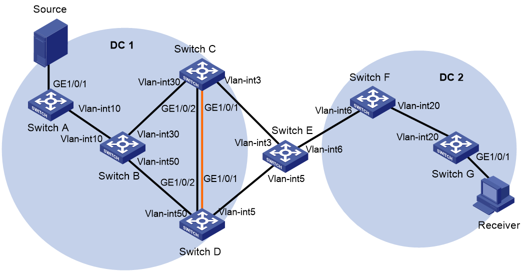
Table 2 Interfaces and IP address assignment
|
Device |
Interface |
IP address |
Device |
Interface |
IP address |
|
Switch A |
Loop0 |
1.1.1.1/32 |
Switch B |
Loop0 |
2.2.2.2/32 |
|
|
Loop1 |
1.1.1.1/32 |
|
Vlan-int10 |
121.121.121.12/24 |
|
|
Vlan-int10 |
121.121.121.1/24 |
|
Vlan-int30 |
123.123.123.12/24 |
|
|
VSI-int1 |
100.1.1.1/24 |
|
Vlan-int50 |
124.124.124.12/24 |
|
Switch C |
Loop0 |
3.3.3.3/32 |
Switch D |
Loop0 |
4.4.4.4/32 |
|
|
Loop1 |
3.3.3.3/32 |
|
Loop1 |
4.4.4.4/32 |
|
|
Loop2 |
1.2.3.4/32 |
|
Loop2 |
1.2.3.4/32 |
|
|
Vlan-int3 |
23.23.23.3/24 |
|
Vlan-int5 |
24.24.24.4/24 |
|
|
Vlan-int30 |
123.123.123.3/24 |
|
Vlan-int50 |
124.124.124.4/24 |
|
Switch E |
Loop0 |
5.5.5.5/32 |
Switch F |
Loop0 |
6.6.6.6/32 |
|
|
Vlan-int3 |
23.23.23.5/24 |
|
Loop1 |
6.6.6.6/32 |
|
|
Vlan-int5 |
24.24.24.5/24 |
|
Vlan-int6 |
26.26.26.6/24 |
|
|
Vlan-int6 |
26.26.26.5/24 |
|
Vlan-int20 |
68.68.68.68/24 |
|
Switch G |
Loop0 |
7.7.7.7/32 |
|
|
|
|
|
Loop1 |
7.7.7.7/32 |
|
|
|
|
|
Vlan-int20 |
68.68.68.7/24 |
|
|
|
|
|
VSI-int1 |
100.1.2.1/24 |
|
|
|
Procedure
1. On the multicast source, specify 100.1.1.1 as the gateway address. On the receiver , specify 100.1.2.1 as the gateway address. (Details not shown.)
2. Configure IP addresses, PIM SM, and unicast routing settings:
# Assign IP addresses to interfaces, as shown in Figure 17. (Details not shown.)
# Configure OSPF in each data center for the switches in a data center to reach one another. (Details not shown.)
# Enable PIM SM on the VLAN interfaces that interconnect the devices in a data center. (Details not shown.)
# Verify that PIM SM is disabled on the VLAN interfaces that interconnect the EDs. (Details not shown.)
# If you enable PIM SM on interfaces connecting EDs, you must use the pim bsr-boundary command configure each ED as a PIM-SM domain border. (Details not shown.)
3. Configure Switch A:
# Enable L2VPN, IP multicast routing, and OSPF process 1.
<SwitchA> system-view
[SwitchA] l2vpn enable
[SwitchA] multicast routing
[SwitchA-mrib] quit
[SwitchA] pim
[SwitchA-pim] quit
[SwitchA] ospf 1
[SwitchA-ospf-1] area 0.0.0.0
[SwitchA-ospf-1-area-0.0.0.0] quit
# Enable the IGMP snooping feature.
[SwitchA] igmp-snooping
[SwitchA-igmp-snooping] quit
# Configure Loopback 0.
[SwitchA] interface loopback 0
[SwitchA-LoopBack0] ip address 1.1.1.1 32
[SwitchA-LoopBack0] ospf 1 area 0.0.0.0
[SwitchA-LoopBack0] pim sm
[SwitchA-LoopBack0] quit
# Create an EVPN instance on VSI vsi1.
[SwitchA] vsi vsi1
[SwitchA-vsi-vsi1] evpn encapsulation vxlan
[SwitchA-vsi-vsi1-evpn-vxlan] route-distinguisher auto
[SwitchA-vsi-vsi1-evpn-vxlan] vpn-target auto export-extcommunity
[SwitchA-vsi-vsi1-evpn-vxlan] vpn-target auto import-extcommunity [SwitchA-vsi-vsi1-evpn-vxlan] quit
# Enable IGMP snooping on VSI vsi1.
[SwitchA-vsi-vsi1] igmp-snooping enable
# Create VXLAN 10.
[SwitchA-vsi-vsi1] vxlan 10
[SwitchA-vsi-vsi1-vxlan-10] quit
[SwitchA-vsi-vsi1] quit
# Configure BGP to advertise BGP EVPN routes, and enable the BGP additional path receiving capability.
[SwitchA] bgp 100
[SwitchA-bgp-default] peer 2.2.2.2 as-number 100
[SwitchA-bgp-default] peer 2.2.2.2 connect-interface loopback 0
[SwitchA-bgp-default] address-family l2vpn evpn
[SwitchA-bgp-default-evpn] peer 2.2.2.2 enable
[SwitchA-bgp-default-evpn] peer 2.2.2.2 additional-paths receive
[SwitchA-bgp-default-evpn] quit
[SwitchA-bgp-default] quit
# On GigabitEthernet 1/0/1, create Ethernet service instance 11 to match VLAN 11.
[SwitchA] interface gigabitethernet 1/0/1
[SwitchA-GigabitEthernet1/0/1] port link-mode bridge
[SwitchA-GigabitEthernet1/0/1] port link-type trunk
[SwitchA-GigabitEthernet1/0/1] port trunk permit vlan 1 11
[SwitchA-GigabitEthernet1/0/1] service-instance 11
[SwitchA-GigabitEthernet1/0/1-srv11] encapsulation s-vid 11
# Map Ethernet service instance 11 to VSI vsi1.
[SwitchA-GigabitEthernet1/0/1-srv11] xconnect vsi vsi1
[SwitchA-GigabitEthernet1/0/1-srv11] quit
# Configure RD and route target settings for VPN instance vpna.
[SwitchA] ip vpn-instance vpna
[SwitchA-vpn-instance-vpna] route-distinguisher 1:1
[SwitchA-vpn-instance-vpna] vpn-target 1:1 import-extcommunity
[SwitchA-vpn-instance-vpna] vpn-target 1:1 export-extcommunity
[SwitchA-vpn-instance-vpna] quit
# Configure VSI-interface 1.
[SwitchA] interface vsi-interface 1
[SwitchA-Vsi-interface1] ip binding vpn-instance vpna
[SwitchA-Vsi-interface1] ip address 100.1.1.1 255.255.255.0
[SwitchA-Vsi-interface1] pim sm
[SwitchA-Vsi-interface1] igmp enable
[SwitchA-Vsi-interface1] mac-address 0001-0001-0001
[SwitchA-Vsi-interface1] distributed-gateway local
[SwitchA-Vsi-interface1] quit
# Associate VSI-interface 2 with VPN instance vpna, and configure the L3 VXLAN ID as 1000 for the VPN instance.
[SwitchA] interface vsi-interface 2
[SwitchA-Vsi-interface2] ip binding vpn-instance vpna
[SwitchA-Vsi-interface2] l3-vni 1000
[SwitchA-Vsi-interface2] pim sm
[SwitchA-Vsi-interface2] quit
# Enable IP multicast routing for VPN instance vpna.
[SwitchA] multicast routing vpn-instance vpna
[SwitchA-mrib-vpna] quit
# Enter VPN instance PIM view, and configure Loopback 1 as a candidate-BSR and candidate-RP in VPN instance vpna.
[SwitchA] pim vpn-instance vpna
[SwitchA-pim-vpna] c-bsr 1.1.1.1
[SwitchA-pim-vpna] c-rp 1.1.1.1
[SwitchA-pim-vpna] quit
# Create an MDT-based MVXLAN for VPN instance vpna and enter MVXLAN IPv4 address family view. Configure the default group, MVXLAN source interface, and data group range settings, and enable advertising active multicast sources through S-PMSI routes.
[SwitchA] multicast-vpn vxlan vpn-instance vpna mode mdt
[SwitchA-mvxlan-vpna] address-family ipv4
[SwitchA-mvxlan-vpna-ipv4] default-group 236.0.0.0
[SwitchA-mvxlan-vpna-ipv4] source loopback 0
[SwitchA-mvxlan-vpna-ipv4] data-group 239.0.0.0 24
[SwitchA-mvxlan-vpna-ipv4] s-pmsi advertise source-active
[SwitchA-mvxlan-vpna-ipv4] quit
[SwitchA-mvxlan-vpna] quit
# Configure Loopback 1.
[SwitchA] interface loopback 1
[SwitchA-LoopBack1] ip binding vpn-instance vpna
[SwitchA-LoopBack1] ip address 1.1.1.1 32
[SwitchA-LoopBack1] pim sm
[SwitchA-LoopBack1] quit
# Specify VSI-interface 1 as the gateway interface for VSI vsi1.
[SwitchA] vsi vsi1
[SwitchA-vsi-vsi1] gateway vsi-interface 1
[SwitchA-vsi-vsi1] quit
4. Configure Switch B:
# Enable IP multicast routing and enable OSPF process 1.
<SwitchB> system-view
[SwitchB] multicast routing
[SwitchB-mrib] quit
[SwitchB] ospf 1
[SwitchB-ospf-1] area 0.0.0.0
[SwitchB-ospf-1-area-0.0.0.0] quit
[SwitchB-ospf-1] quit
# Configure Loopback 0.
[SwitchB] interface loopback 0
[SwitchB-LoopBack0] ip address 2.2.2.2 32
[SwitchB-LoopBack0] ospf 1 area 0.0.0.0
[SwitchB-LoopBack0] pim sm
# Configure BGP to advertise BGP EVPN routes, enable the BGP additional path receiving capability, and set the maximum number of Add-Path optimal routes that can be advertised to the peer group. The maximum number of Add-Path optimal routes must be greater than or equal to the number of peer EDs.
[SwitchB] bgp 100
[SwitchB-bgp-default] group evpn internal
[SwitchB-bgp-default] peer evpn connect-interface loopback 0
[SwitchB-bgp-default] group vtep internal
[SwitchB-bgp-default] peer vtep connect-interface loopback 0
[SwitchB-bgp-default] peer 1.1.1.1 group vtep
[SwitchB-bgp-default] peer 3.3.3.3 group evpn
[SwitchB-bgp-default] peer 4.4.4.4 group evpn
[SwitchB-bgp-default-evpn] undo policy vpn-target
[SwitchB-bgp-default-evpn] additional-paths select-best 2
[SwitchB-bgp-default-evpn] peer evpn enable
[SwitchB-bgp-default-evpn] peer evpn reflect-client
[SwitchB-bgp-default-evpn] peer vtep enable
[SwitchB-bgp-default-evpn] peer vtep reflect-client
[SwitchB-bgp-default-evpn] peer vtep additional-paths send
[SwitchB-bgp-default-evpn] peer vtep advertise additional-paths best 2
[SwitchB-bgp-default-evpn] quit
[SwitchB-bgp-default] quit
5. Configure Switch C:
# Enable L2VPN, IP multicast routing, OSPF process 1, and RIP process 1.
<SwitchC> system-view
[SwitchC] l2vpn enable
[SwitchC] multicast routing
[SwitchC-mrib] quit
[SwitchC] pim
[SwitchC-pim] quit
[SwitchC] ospf 1
[SwitchC-ospf-1] area 0.0.0.0
[SwitchC-ospf-1-area-0.0.0.0] quit
[SwitchC-ospf-1] quit
[SwitchC] rip 1
[SwitchC-rip-1] quit
# Enable the IGMP snooping feature.
[SwitchC] igmp-snooping
[SwitchC-igmp-snooping] quit
# On GigabitEthernet 1/0/3, enable RIP and DCI multicast.
[SwitchC] interface gigabitethernet 1/0/3
[SwitchC-GigabitEthernet1/0/3] rip 1 enable
[SwitchC-GigabitEthernet1/0/3] dci enable
[SwitchC-GigabitEthernet1/0/3] quit
# Specify the virtual ED address as 1.2.3.4.
[SwitchC] evpn m-lag group 1.2.3.4
# Configure RD and route target settings for VPN instance vpna.
[SwitchC] ip vpn-instance vpna
[SwitchC-vpn-instance-vpna] route-distinguisher 3:3
[SwitchC-vpn-instance-vpna] vpn-target 1:1 import-extcommunity
[SwitchC-vpn-instance-vpna] vpn-target 1:1 export-extcommunity
[SwitchC-vpn-instance-vpna] quit
# Configure Loopback 0.
[SwitchC] interface loopback 0
[SwitchC-LoopBack0] ip address 3.3.3.3 32
[SwitchC-LoopBack0] ospf 1 area 0.0.0.0
[SwitchC-LoopBack0] rip 1 enable
[SwitchC-LoopBack0] pim sm
# Configure Loopback 1.
[SwitchC] interface loopback 1
[SwitchC-LoopBack1] ip binding vpn-instance vpna
[SwitchC-LoopBack1] ip address 3.3.3.3 32
[SwitchC-LoopBack1] pim sm
[SwitchC-LoopBack1] quit
# Configure Loopback 2.
[SwitchC] interface loopback 2
[SwitchC-LoopBack2] ip address 1.2.3.4 32
[SwitchC-LoopBack2] ospf 1 area 0.0.0.0
[SwitchC-LoopBack2] rip 1 enable
[SwitchC-LoopBack2] quit
# Create VSI-interface 2, associate the VSI interface with VPN instance vpna, and configure the L3 VXLAN ID as 1000 for the VPN instance.
[SwitchC] interface vsi-interface 2
[SwitchC-Vsi-interface2] ip binding vpn-instance vpna
[SwitchC-Vsi-interface2] l3-vni 1000
[SwitchC-Vsi-interface2] pim sm
[SwitchC-Vsi-interface2] quit
# Enable IP multicast routing in VPN instance vpna.
[SwitchC] multicast routing vpn-instance vpna
[SwitchC-mrib-vpna] quit
# Enter VPN instance PIM view, and configure Loopback 1 as a candidate-BSR and candidate-RP in VPN instance vpna.
[SwitchC] pim vpn-instance vpna
[SwitchC-pim-vpna] c-bsr 3.3.3.3
[SwitchC-pim-vpna] c-rp 3.3.3.3
[SwitchC-pim-vpna] quit
# Create an MDT-based MVXLAN for VPN instance vpna and enter MVXLAN IPv4 address family view. Configure the default group, MVXLAN source interface, and data group range settings, and enable DCI multicast.
[SwitchC] multicast-vpn vxlan vpn-instance vpna mode mdt
[SwitchC-mvxlan-vpna] address-family ipv4
[SwitchC-mvxlan-vpna-ipv4] default-group 236.0.0.0
[SwitchC-mvxlan-vpna-ipv4] source loopback 2 evpn-drni-group
[SwitchC-mvxlan-vpna-ipv4] data-group 239.0.0.0 24
[SwitchC-mvxlan-vpna-ipv4] dci enable
# Specify the IP addresses of the member devices in the M-LAG system.
[SwitchC-mvxlan-vpna-ipv4] m-lag local 3.3.3.3 remote 4.4.4.4
[SwitchC-mvxlan-vpna-ipv4] quit
[SwitchC-mvxlan-vpna] quit
# Configure a routing policy, so Switch C modifies the next hop as 3.3.3.3 when sending an S-PMSI route to Switch B.
[SwitchC] route-policy rt_spmsi permit node 0
[SwitchC-route-policy-rt_spmsi-0] if-match route-type bgp-evpn-s-pmsi
[SwitchC-route-policy-rt_spmsi-0] apply ip-address next-hop 3.3.3.3
[SwitchC-route-policy-rt_spmsi-0] quit
[SwitchC] route-policy rt_spmsi permit node 1
[SwitchC-route-policy-rt_spmsi-1] quit
# Configure BGP to advertise BGP EVPN routes, and set the virtual ED address as the next hop for the advertised routes.
[SwitchC] bgp 100
[SwitchC-bgp-default] peer 2.2.2.2 as-number 100
[SwitchC-bgp-default] peer 2.2.2.2 connect-interface loopback 0
[SwitchC-bgp-default] peer 6.6.6.6 as-number 200
[SwitchC-bgp-default] peer 6.6.6.6 connect-interface loopback 0
[SwitchC-bgp-default] peer 6.6.6.6 ebgp-max-hop 64
[SwitchC-bgp-default] address-family l2vpn evpn
[SwitchC-bgp-default-evpn] nexthop evpn-m-lag group-address
[SwitchC-bgp-default-evpn] peer 2.2.2.2 enable
[SwitchC-bgp-default-evpn] peer 2.2.2.2 route-policy rt_spmsi export
[SwitchC-bgp-default-evpn] peer 2.2.2.2 next-hop-local
[SwitchC-bgp-default-evpn] peer 6.6.6.6 enable
[SwitchC-bgp-default-evpn] peer 6.6.6.6 router-mac-local
[SwitchC-bgp-default-evpn] quit
[SwitchC-bgp-default] quit
# Configure Layer 2 dynamic aggregate interface Bridge-Aggregation 9, and specify it as the peer-link interface.
[SwitchC] interface bridge-aggregation 9
[SwitchC-Bridge-Aggregation9] port link-type trunk
[SwitchC-Bridge-Aggregation9] port trunk permit vlan all
[SwitchC-Bridge-Aggregation9] link-aggregation mode dynamic
[SwitchC-Bridge-Aggregation9] port m-lag peer-link 1
[SwitchC-Bridge-Aggregation9] quit
# Assign GigabitEthernet 1/0/2 to link aggregation group 9.
[SwitchC] interface gigabitethernet 1/0/2
[SwitchC-GigabitEthernet1/0/2] port link-aggregation group 9
[SwitchC-GigabitEthernet1/0/2] quit
# Add GigabitEthernet 1/0/2 to the user-configured list of excluded ports.
[SwitchC] m-lag mad exclude interface gigabitethernet 1/0/1
# Configure M-LAG system settings.
[SwitchC] m-lag restore-delay 180
[SwitchC] m-lag system-mac 0001-0001-0001
[SwitchC] m-lag system-number 1
[SwitchC] m-lag system-priority 10
[SwitchC] m-lag keepalive ip destination 60.1.1.2 source 60.1.1.1
6. Configure Switch D:
# Enable L2VPN, IP multicast routing, OSPF process 1, and RIP process 1.
<SwitchD> system-view
[SwitchD] l2vpn enable
[SwitchD] multicast routing
[SwitchD-mrib] quit
[SwitchD] pim
[SwitchD-pim] quit
[SwitchD] ospf 1
[SwitchD-ospf-1] area 0.0.0.0
[SwitchD-ospf-1-area-0.0.0.0] quit
[SwitchD-ospf-1] quit
[SwitchD] rip 1
[SwitchD-rip-1] quit
# Enable the IGMP snooping feature.
[SwitchD] igmp-snooping
[SwitchD-igmp-snooping] quit
# On GigabitEthernet 1/0/2, enable RIP and DCI multicast.
[SwitchD] interface gigabitethernet 1/0/3
[SwitchD-GigabitEthernet1/0/3] rip 1 enable
[SwitchD-GigabitEthernet1/0/3] dci enable
[SwitchD-GigabitEthernet1/0/3] quit
# Specify the virtual ED address as 1.2.3.4.
[SwitchD] evpn m-lag group 1.2.3.4
# Configure RD and route target settings for VPN instance vpna.
[SwitchD] ip vpn-instance vpna
[SwitchD-vpn-instance-vpna] route-distinguisher 3:3
[SwitchD-vpn-instance-vpna] vpn-target 1:1 import-extcommunity
[SwitchD-vpn-instance-vpna] vpn-target 1:1 export-extcommunity
[SwitchD-vpn-instance-vpna] quit
# Configure Loopback 0.
[SwitchD] interface loopback 0
[SwitchD-LoopBack0] ip address 4.4.4.4 32
[SwitchD-LoopBack0] ospf 1 area 0.0.0.0
[SwitchD-LoopBack0] rip 1 enable
[SwitchD-LoopBack0] pim sm
# Configure Loopback 1.
[SwitchD] interface loopback 1
[SwitchD-LoopBack1] ip binding vpn-instance vpna
[SwitchD-LoopBack1] ip address 4.4.4.4 32
[SwitchD-LoopBack1] pim sm
[SwitchD-LoopBack1] quit
# Configure Loopback 2.
[SwitchD] interface loopback 2
[SwitchD-LoopBack2] ip address 1.2.3.4 32
[SwitchD-LoopBack2] ospf 1 area 0.0.0.0
[SwitchD-LoopBack2] rip 1 enable
[SwitchD-LoopBack2] quit
# Associate VSI-interface 2 with VPN instance vpna, and configure the L3 VXLAN ID as 1000 for the VPN instance.
[SwitchD] interface vsi-interface 2
[SwitchD-Vsi-interface2] ip binding vpn-instance vpna
[SwitchD-Vsi-interface2] l3-vni 1000
[SwitchD-Vsi-interface2] pim sm
[SwitchD-Vsi-interface2] quit
# Enable IP multicast routing in VPN instance vpna.
[SwitchD] multicast routing vpn-instance vpna
[SwitchD-mrib-vpna] quit
# Enter VPN instance PIM view, and configure Loopback 1 as a candidate-BSR and candidate-RP in VPN instance vpna.
[SwitchD] pim vpn-instance vpna
[SwitchD-pim-vpna] c-bsr 4.4.4.4
[SwitchD-pim-vpna] c-rp 4.4.4.4
[SwitchD-pim-vpna] quit
# Create an MDT-based MVXLAN for VPN instance vpna and enter MVXLAN IPv4 address family view. Configure the default group, MVXLAN source interface, and data group range settings, and enable DCI multicast.
[SwitchD] multicast-vpn vxlan vpn-instance a mode mdt
[SwitchD-mvxlan-a] address-family ipv4
[SwitchD-mvxlan-a-ipv4] default-group 236.0.0.0
[SwitchD-mvxlan-a-ipv4] source loopback 2 evpn-drni-group
[SwitchD-mvxlan-a-ipv4] data-group 239.0.0.0 24
[SwitchD-mvxlan-a-ipv4] dci enable
# Specify the IP addresses of the member devices in the M-LAG system.
[SwitchD-mvxlan-a-ipv4] m-lag local 4.4.4.4 remote 3.3.3.3
[SwitchD-mvxlan-a-ipv4] quit
[SwitchD-mvxlan-a] quit
# Configure a routing policy, so Switch D modifies the next hop as 4.4.4.4 when sending an S-PMSI route to Switch B.
[SwitchD] route-policy rt_spmsi permit node 0
[SwitchD-route-policy-rt_spmsi-0] if-match route-type bgp-evpn-s-pmsi
[SwitchD-route-policy-rt_spmsi-0] apply ip-address next-hop 4.4.4.4
[SwitchD-route-policy-rt_spmsi-0] quit
[SwitchD] route-policy rt_spmsi permit node 1
[SwitchD-route-policy-rt_spmsi-1] quit
# Configure BGP to advertise BGP EVPN routes, and set the virtual ED address as the next hop for the advertised routes.
[SwitchC] bgp 100
[SwitchD-bgp-default] peer 2.2.2.2 as-number 100
[SwitchD-bgp-default] peer 2.2.2.2 connect-interface loopback 0
[SwitchD-bgp-default] peer 6.6.6.6 as-number 200
[SwitchD-bgp-default] peer 6.6.6.6 connect-interface loopback 0
[SwitchD-bgp-default] peer 6.6.6.6 ebgp-max-hop 64
[SwitchD-bgp-default] address-family l2vpn evpn
[SwitchD-bgp-default-evpn] nexthop evpn-m-lag group-address
[SwitchD-bgp-default-evpn] peer 2.2.2.2 enable
[SwitchD-bgp-default-evpn] peer 2.2.2.2 route-policy rt_spmsi export
[SwitchD-bgp-default-evpn] peer 2.2.2.2 next-hop-local
[SwitchD-bgp-default-evpn] peer 6.6.6.6 enable
[SwitchD-bgp-default-evpn] peer 6.6.6.6 router-mac-local
[SwitchD-bgp-default-evpn] quit
[SwitchD-bgp-default] quit
# Configure Layer 2 dynamic aggregate interface Bridge-Aggregation 9, and specify it as the peer-link interface.
[SwitchD] interface bridge-aggregation 9
[SwitchD-Bridge-Aggregation9] port link-type trunk
[SwitchD-Bridge-Aggregation9] port trunk permit vlan all
[SwitchD-Bridge-Aggregation9] link-aggregation mode dynamic
[SwitchD-Bridge-Aggregation9] port m-lag peer-link 1
[SwitchD-Bridge-Aggregation9] quit
# Assign GigabitEthernet 1/0/2 to link aggregation group 9.
[SwitchD] interface gigabitethernet 1/0/2
[SwitchD-GigabitEthernet1/0/2] port link-aggregation group 9
[SwitchD-GigabitEthernet1/0/2] quit
# Add GigabitEthernet 1/0/2 to the user-configured list of excluded ports.
[SwitchC] m-lag mad exclude interface gigabitethernet 1/0/1
# Configure M-LAG system settings.
[SwitchD] m-lag restore-delay 180
[SwitchD] m-lag system-mac 0001-0001-0001
[SwitchD] m-lag system-number 2
[SwitchD] m-lag system-priority 10
[SwitchD] m-lag keepalive ip destination 60.1.1.1 source 60.1.1.2
7. Configure Switch E:
# Enable RIP process 1.
<SwitchE> system-view
[SwitchE] rip 1
[SwitchE-rip-1] quit
# Enable RIP on interfaces.
[SwitchE] interface vlan-interface 3
[SwitchE-Vlan-interface3] rip 1 enable
[SwitchE-Vlan-interface3] quit
[SwitchE] interface vlan-interface 5
[SwitchE-Vlan-interface5] rip 1 enable
[SwitchE-Vlan-interface5] quit
[SwitchE] interface vlan-interface 6
[SwitchE-Vlan-interface6] rip 1 enable
[SwitchE-Vlan-interface6] quit
8. Configure Switch F:
# Enable L2VPN, IP multicast routing, OSPF process 1, and RIP process 1.
<SwitchF> system-view
[SwitchF] l2vpn enable
[SwitchF] multicast routing
[SwitchF-mrib] quit
[SwitchF] pim
[SwitchF-pim] quit
[SwitchF] ospf 1
[SwitchF-ospf-1] area 0.0.0.0
[SwitchF-ospf-1-area-0.0.0.0] quit
[SwitchF-ospf-1] quit
[SwitchF] rip 1
[SwitchF-rip-1] quit
# Enable the IGMP snooping feature.
[SwitchF] igmp-snooping
[SwitchF-igmp-snooping] quit
# Configure Loopback 0.
[SwitchF] interface loopback 0
[SwitchF-LoopBack0] ip address 6.6.6.6 32
[SwitchF-LoopBack0] pim sm
[SwitchF-LoopBack0] ospf 1 area 0.0.0.0
[SwitchF-LoopBack0] quit
# On GigabitEthernet 1/0/2, configure OSPF and DCI multicast.
[SwitchD] interface gigabitethernet 1/0/3
[SwitchD-GigabitEthernet1/0/3] ospf 1 area 0
[SwitchD-GigabitEthernet1/0/3] dci enable
# Configure RD and route target settings for VPN instance vpna.
[SwitchF] ip vpn-instance vpna
[SwitchF-vpn-instance-vpna] route-distinguisher 6:6
[SwitchF-vpn-instance-vpna] vpn-target 1:1 import-extcommunity
[SwitchF-vpn-instance-vpna] vpn-target 1:1 export-extcommunity
[SwitchF-vpn-instance-vpna] quit
# Create VSI-interface 2, and associate the VSI interface with VPN instance vpna, and configure the L3 VXLAN ID as 1000 for the VPN instance.
[SwitchF] interface vsi-interface 2
[SwitchF-Vsi-interface2] ip binding vpn-instance vpna
[SwitchF-Vsi-interface2] l3-vni 1000
[SwitchF-Vsi-interface2] pim sm
[SwitchF-Vsi-interface2] quit
# Configure Loopback 1.
[SwitchF] interface loopback 1
[SwitchF-LoopBack1] ip binding vpn-instance vpna
[SwitchF-LoopBack1] ip address 6.6.6.6 32
[SwitchF-LoopBack1] pim sm
[SwitchF-LoopBack1] quit
# Enter VPN instance PIM view, and configure Loopback 1 as a candidate-BSR and candidate-RP in VPN instance vpna.
[SwitchF] pim vpn-instance vpna
[SwitchF-pim-vpna] c-bsr 6.6.6.6
[SwitchF-pim-vpna] c-rp 6.6.6.6
[SwitchF-pim-vpna] quit
# Enable IP multicast routing in VPN instance vpna.
[SwitchF] multicast routing vpn-instance vpna
[SwitchF-mrib-vpna] quit
# Create an MDT-based MVXLAN for VPN instance vpna and enter MVXLAN IPv4 address family view. Configure the default group, MVXLAN source interface, and data group range settings. Enable DCI multicast.
[SwitchF] multicast-vpn vxlan vpn-instance vpna mode mdt
[SwitchF-mvxlan-vpna] address-family ipv4
[SwitchF-mvxlan-vpna-ipv4] default-group 236.0.0.0
[SwitchF-mvxlan-vpna-ipv4] source loopback 0
[SwitchF-mvxlan-vpna-ipv4] data-group 239.0.0.0 24
[SwitchF-mvxlan-vpna-ipv4] dci enable
[SwitchF-mvxlan-vpna-ipv4] quit
[SwitchF-mvxlan-vpna] quit
# Configure BGP to advertise BGP EVPN routes.
[SwitchF] bgp 200
[SwitchF-bgp-default] peer 3.3.3.3 as-number 100
[SwitchF-bgp-default] peer 3.3.3.3 connect-interface loopback 0
[SwitchF-bgp-default] peer 3.3.3.3 ebgp-max-hop 64
[SwitchF-bgp-default] peer 4.4.4.4 as-number 100
[SwitchF-bgp-default] peer 4.4.4.4 connect-interface loopback 0
[SwitchF-bgp-default] peer 4.4.4.4 ebgp-max-hop 64
[SwitchF-bgp-default] peer 7.7.7.7 as-number 200
[SwitchF-bgp-default] peer 7.7.7.7 connect-interface loopback 0
[SwitchF-bgp-default] address-family l2vpn evpn
[SwitchF-bgp-default-evpn] peer 3.3.3.3 enable
[SwitchF-bgp-default-evpn] peer 3.3.3.3 router-mac-local
[SwitchF-bgp-default-evpn] peer 4.4.4.4 enable
[SwitchF-bgp-default-evpn] peer 4.4.4.4 router-mac-local
[SwitchF-bgp-default-evpn] peer 7.7.7.7 enable
[SwitchF-bgp-default-evpn] peer 7.7.7.7 next-hop-local
[SwitchF-bgp-default-evpn] quit
[SwitchF-bgp-default] quit
9. Configure Switch G:
# Enable L2VPN, IP multicast routing, and OSPF process 1.
<SwitchG> system-view
[SwitchG] l2vpn enable
[SwitchG] multicast routing
[SwitchG-mrib] quit
[SwitchG] pim
[SwitchG-pim] quit
[SwitchG] ospf 1
[SwitchG-ospf-1] area 0.0.0.0
[SwitchG-ospf-1-area-0.0.0.0] quit
# Enable the IGMP snooping feature.
[SwitchG] igmp-snooping
[SwitchG-igmp-snooping] quit
# Configure Loopback 0.
[SwitchG] interface loopback 0
[SwitchG-LoopBack0] ip address 7.7.7.7 32
[SwitchG-LoopBack0] pim sm
[SwitchG-LoopBack0] ospf 1 area 0.0.0.0
[SwitchG-LoopBack0] quit
# Create an EVPN instance on VSI vsi1.
[SwitchG] vsi vsi1
[SwitchG-vsi-vsi1] evpn encapsulation vxlan
[SwitchG-vsi-vsi1-evpn-vxlan] route-distinguisher auto
[SwitchG-vsi-vsi1-evpn-vxlan] vpn-target auto export-extcommunity
[SwitchG-vsi-vsi1-evpn-vxlan] vpn-target auto import-extcommunity [SwitchG-vsi-vsi1-evpn-vxlan] quit
# Enable IGMP snooping on VSI vsi1.
[SwitchG-vsi-vsi1] igmp-snooping enable
# Create VXLAN 10.
[SwitchG-vsi-vsi1] vxlan 10
[SwitchG-vsi-vsi1-vxlan-10] quit
[SwitchG-vsi-vsi1] quit
# Configure BGP to advertise BGP EVPN routes.
[SwitchG] bgp 200
[SwitchG-bgp-default] peer 6.6.6.6 as-number 200
[SwitchG-bgp-default] peer 6.6.6.6 connect-interface loopback 0
[SwitchG-bgp-default] address-family l2vpn evpn
[SwitchG-bgp-default-evpn] peer 6.6.6.6 enable
[SwitchG-bgp-default-evpn] quit
[SwitchG-bgp-default] quit
# On GigabitEthernet 1/0/1, create Ethernet service instance 33 to match VLAN 33.
[SwitchG] interface gigabitethernet 1/0/1
[SwitchG-GigabitEthernet1/0/1] port link-mode bridge
[SwitchG-GigabitEthernet1/0/1] port link-type trunk
[SwitchG-GigabitEthernet1/0/1] port trunk permit vlan 1 33
[SwitchG-GigabitEthernet1/0/1] service-instance 33
[SwitchG-GigabitEthernet1/0/1-srv33] encapsulation s-vid 33
# Map Ethernet service instance 33 to VSI vsi1.
[SwitchG-GigabitEthernet1/0/1-srv33] xconnect vsi vsi1
[SwitchG-GigabitEthernet1/0/1-srv33] quit
# Configure RD and route target settings for VPN instance vpna.
[SwitchG] ip vpn-instance vpna
[SwitchG-vpn-instance-vpna] route-distinguisher 8:8
[SwitchG-vpn-instance-vpna] vpn-target 1:1 import-extcommunity
[SwitchG-vpn-instance-vpna] vpn-target 1:1 export-extcommunity
[SwitchG-vpn-instance-vpna] quit
# Configure VSI-interface 1.
[SwitchG] interface vsi-interface 1
[SwitchG-Vsi-interface1] ip binding vpn-instance vpna
[SwitchG-Vsi-interface1] ip address 100.1.2.1 255.255.255.0
[SwitchG-Vsi-interface1] pim sm
[SwitchG-Vsi-interface1] igmp enable
[SwitchG-Vsi-interface1] mac-address 0001-0001-0001
[SwitchG-Vsi-interface1] distributed-gateway local
[SwitchG-Vsi-interface1] quit
# Create VSI-interface 2, and associate the VSI interface with VPN instance vpna, and configure the L3 VXLAN ID as 1000 for the VPN instance.
[SwitchG] interface vsi-interface 2
[SwitchG-Vsi-interface2] ip binding vpn-instance vpna
[SwitchG-Vsi-interface2] l3-vni 1000
[SwitchG-Vsi-interface2] pim sm
[SwitchG-Vsi-interface2] quit
# Enable IP multicast routing for VPN instance vpna.
[SwitchG] multicast routing vpn-instance vpna
[SwitchG-mrib-vpna] quit
# Create an MDT-based MVXLAN for VPN instance vpna and enter MVXLAN IPv4 address family view. Configure the default group, MVXLAN source interface, and data group range settings, and enable advertising active multicast sources through S-PMSI routes.
[SwitchG] multicast-vpn vxlan vpn-instance vpna mode mdt
[SwitchG-mvxlan-vpna] address-family ipv4
[SwitchG-mvxlan-vpna-ipv4] default-group 236.0.0.0
[SwitchG-mvxlan-vpna-ipv4] source loopback 0
[SwitchG-mvxlan-vpna-ipv4] data-group 239.0.0.0 24
[SwitchG-mvxlan-vpna-ipv4] s-pmsi advertise source-active
[SwitchG-mvxlan-vpna-ipv4] quit
[SwitchG-mvxlan-vpna] quit
# Configure Loopback 1.
[SwitchG] interface loopback 1
[SwitchG-LoopBack1] ip binding vpn-instance vpna
[SwitchG-LoopBack1] ip address 7.7.7.7 32
[SwitchG-LoopBack1] pim sm
[SwitchG-LoopBack1] quit
# Enter VPN instance PIM view, and configure Loopback 1 as a candidate-BSR and candidate-RP in VPN instance vpna.
[SwitchG] pim vpn-instance vpna
[SwitchG-pim-vpna] c-bsr 7.7.7.7
[SwitchG-pim-vpna] c-rp 7.7.7.7
[SwitchG-pim-vpna] quit
# Specify VSI-interface 1 as the gateway interface for VSI vsi1.
[SwitchG] vsi vsi1
[SwitchG-vsi-vsi1] gateway vsi-interface vsi1
[SwitchG-vsi-vsi1] quit
Verifying the configuration
1. Verify the multicast routing information on the VTEPs.
# Verify that Switch A has multicast routing entries for VPN instance vpna and the public network.
<SwitchA> display pim vpn-instance vpna routing-table
Total 1 (*, G) entries; 1 (S, G) entries
(*, 225.0.0.1)
RP: 1.1.1.1 (local)
Protocol: pim-sm, Flag: WC RC
UpTime: 00:00:31
Upstream interface: Register-Tunnel0
Upstream neighbor: NULL
RPF prime neighbor: NULL
Downstream interface information:
Total number of downstream interfaces: 1
1: MTunnel0
Protocol: MD, UpTime: 00:00:31, Expires: -
(100.1.1.100, 225.0.0.1)
RP: 1.1.1.1 (local)
Protocol: pim-sm, Flag: SPT 2MSDP LOC ACT SQ RC 2MVPN
UpTime: 00:00:32
Upstream interface: Vsi-interface1
Upstream neighbor: NULL
RPF prime neighbor: NULL
Downstream interface information:
Total number of downstream interfaces: 1
1: MTunnel1
Protocol: MD, UpTime: 00:00:26, Expires: -
<SwitchA> display pim routing-table
Total 0 (*, G) entries; 6 (S, G) entries
(1.1.1.1, 236.0.0.0)
RP: NULL
Protocol: pim-sm, Flag: SPT LOC VXLAN_L3
UpTime: 00:03:31
Upstream interface: MTunnel0 (VPN: vpna)
Upstream neighbor: NULL
RPF prime neighbor: NULL
Downstream interface information:
Total number of downstream interfaces: 1
1: Vlan-interface10
Protocol: pim-sm, UpTime: 00:01:53, Expires: 00:02:38
(3.3.3.3, 236.0.0.0)
RP: NULL
Protocol: pim-sm, Flag: SPT
UpTime: 00:01:53
Upstream interface: Vlan-interface10
Upstream neighbor: 121.121.121.12
RPF prime neighbor: 121.121.121.12
Downstream interface information:
Total number of downstream interfaces: 1
1: MVXLAN-UPE0
Protocol: MD, UpTime: 00:01:53, Expires: -
(4.4.4.4, 236.0.0.0)
RP: NULL
Protocol: pim-sm, Flag: SPT
UpTime: 00:01:47
Upstream interface: Vlan-interface10
Upstream neighbor: 121.121.121.12
RPF prime neighbor: 121.121.121.12
Downstream interface information:
Total number of downstream interfaces: 1
1: MVXLAN-UPE0
Protocol: MD, UpTime: 00:01:47, Expires: -
(1.1.1.1, 239.0.0.0)
RP: NULL
Protocol: pim-sm, Flag: SPT LOC VXLAN_L3
UpTime: 00:00:51
Upstream interface: MTunnel1 (VPN: vpna)
Upstream neighbor: NULL
RPF prime neighbor: NULL
Downstream interface information:
Total number of downstream interfaces: 1
1: Vlan-interface10
Protocol: pim-sm, UpTime: 00:00:51, Expires: 00:02:40
# Verify that Switch G has multicast routing entries for VPN instance vpna and the public network.
<SwitchG> display pim vpn-instance vpna routing-table
Total 1 (*, G) entries; 1 (S, G) entries
(*, 225.0.0.1)
RP: 7.7.7.7 (local)
Protocol: pim-sm, Flag: WC RC
UpTime: 00:12:32
Upstream interface: Register-Tunnel0
Upstream neighbor: NULL
RPF prime neighbor: NULL
Downstream interface information:
Total number of downstream interfaces: 2
1: Vsi-interface1
Protocol: igmp, UpTime: 00:12:32, Expires: -
2: MTunnel0
Protocol: MD, UpTime: 00:12:31, Expires: -
(100.1.1.100, 225.0.0.1)
RP: 7.7.7.7 (local)
Protocol: pim-sm, Flag: SPT 2MSDP ACT RQ SRC-ACT 2MVPN FROMVXLAN
UpTime: 00:12:30
Upstream interface: MVXLAN-UPE0 (0.0.0.0)
Upstream neighbor: NULL
RPF prime neighbor: NULL
Downstream interface information:
Total number of downstream interfaces: 1
1: Vsi-interface1
Protocol: pim-sm, UpTime: 00:12:21, Expires: -
<SwitchG> display pim routing-table
Total 0 (*, G) entries; 5 (S, G) entries
(6.6.6.6, 236.0.0.0)
RP: NULL
Protocol: pim-sm, Flag: SPT
UpTime: 00:19:27
Upstream interface: Vlan-interface20
Upstream neighbor: 68.68.68.68
RPF prime neighbor: 68.68.68.68
Downstream interface information:
Total number of downstream interfaces: 1
1: MVXLAN-UPE0
Protocol: MD, UpTime: 00:19:27, Expires: -
(7.7.7.7, 236.0.0.0)
RP: NULL
Protocol: pim-sm, Flag: SPT
UpTime: 00:19:29
Upstream interface: Vlan-interface20
Upstream neighbor: 78.78.78.78
RPF prime neighbor: 78.78.78.78
Downstream interface information:
Total number of downstream interfaces: 1
1: MVXLAN-UPE0
Protocol: MD, UpTime: 00:19:29, Expires: -
(6.6.6.6, 239.0.0.0)
RP: NULL
Protocol: pim-sm, Flag: SPT ACT 2MVPN
UpTime: 00:18:04
Upstream interface: Vlan-interface20
Upstream neighbor: 68.68.68.68
RPF prime neighbor: 68.68.68.68
Downstream interface information:
Total number of downstream interfaces: 1
1: MVXLAN-UPE0
Protocol: MD, UpTime: 00:18:04, Expires: -
2. Verify the multicast routing information on the EDs.
# Verify that Switch C has multicast routing entries for VPN instance vpna and the public network.
<SwitchC> display pim vpn-instance vpna routing-table
Total 1 (*, G) entries; 1 (S, G) entries
(*, 225.0.0.1)
RP: 3.3.3.3 (local)
Protocol: pim-sm, Flag: WC RC
UpTime: 00:20:48
Upstream interface: Register-Tunnel0
Upstream neighbor: NULL
RPF prime neighbor: NULL
Downstream interface information:
Total number of downstream interfaces: 2
1: Vsi-interface2
Protocol: MD, UpTime: 00:20:48, Expires: -
2: MTunnel0
Protocol: MD, UpTime: 00:20:48, Expires: -
(100.1.1.100, 225.0.0.1)
RP: 3.3.3.3 (local)
Protocol: pim-sm, Flag: SPT 2MSDP ACT RQ SRC-ACT 2MVPN FROMVXLAN
UpTime: 00:20:47
Upstream interface: MVXLAN-UPE0 (0.0.0.0)
Upstream neighbor: NULL
RPF prime neighbor: NULL
Downstream interface information:
Total number of downstream interfaces: 1
1: Vsi-interface2
Protocol: MD, UpTime: 00:20:47, Expires: -
<SwitchC> display pim routing-table
Total 0 (*, G) entries; 4 (S, G) entries
(1.1.1.1, 236.0.0.0)
RP: NULL
Protocol: pim-sm, Flag: SPT
UpTime: 00:23:32
Upstream interface: Vlan-interface30
Upstream neighbor: 123.123.123.12
RPF prime neighbor: 123.123.123.12
Downstream interface information:
Total number of downstream interfaces: 1
1: MVXLAN-UPE0
Protocol: MD, UpTime: 00:23:32, Expires: -
(3.3.3.3, 236.0.0.0)
RP: NULL
Protocol: pim-sm, Flag: SPT LOC VXLAN_L3
UpTime: 00:25:33
Upstream interface: MTunnel0 (VPN: a)
Upstream neighbor: NULL
RPF prime neighbor: NULL
Downstream interface information:
Total number of downstream interfaces: 1
1: Vlan-interface30
Protocol: pim-sm, UpTime: 00:23:32, Expires: 00:02:58
(1.1.1.1, 239.0.0.0)
RP: NULL
Protocol: pim-sm, Flag: SPT ACT 2MVPN
UpTime: 00:22:31
Upstream interface: Vlan-interface30
Upstream neighbor: 123.123.123.12
RPF prime neighbor: 123.123.123.12
Downstream interface information:
Total number of downstream interfaces: 1
1: MVXLAN-UPE0
Protocol: MD, UpTime: 00:22:31, Expires: -