- Table of Contents
- Related Documents
-
| Title | Size | Download |
|---|---|---|
| 01-Intallation Guide | 4.30 MB |
Examining the installation site
Installing the switch in a tank
Tank-mounting procedures at a glance
Removing mounting brackets and attaching them to the chassis
Mounting the switch in the tank
Installing/removing power modules
Installing/removing liquid-cooled transceiver modules
Installing a liquid-cooled transceiver module
Removing a liquid-cooled transceiver module
Connecting/disconnecting liquid-cooled cables
Connecting liquid-cooled cables
Disconnecting liquid-cooled cables
3 Accessing the switch for the first time
Connecting the switch to a configuration terminal
Connecting a DB9-to-RJ45 console cable
Connecting a USB-to-RJ45 console cable
Planning IRF fabric size and the installation site
Identifying the master switch and planning IRF member IDs
Planning IRF topology and connections
Identifying physical IRF ports on the member switches
Configuring basic IRF settings
Connecting the physical IRF ports
Accessing the IRF fabric to verify the configuration
Planning for setting up an M-LAG system
Determining device installation locations
Reserving physical ports for M-LAG connection
Planning the cable connection scheme
Configuring the M-LAG system settings
Connecting the M-LAG member switches
6 Maintenance and troubleshooting
Configuration terminal display issues
No display on the configuration terminal
Garbled display on the configuration terminal
1 Preparing for installation
This document is applicable to the H3C S6850-56HF-IM immersion-cooled Ethernet switch (product code LS-6850-56HF-IM).
Safety recommendations
To avoid bodily injury or damage to the switch, read the following safety recommendations carefully before working with the switch. Note that the recommendations do not cover every possible hazardous condition.
· Before cleaning the switch, remove all power cords from the switch. Do not clean the switch with water.
· Do not place the switch near water or in a damp environment. Prevent water or moisture from entering the switch chassis.
· Do not place the switch on an unstable case or desk.
· Make sure the power source voltage meets the requirements of the switch.
· When you replace a power module, turn off the circuit breaker for it.
Examining the installation site
Make sure the installation site meet the requirements of temperature, cleanliness, and corrosive gas limit. For more information about the installation site requirements, see H3C Immersion Cooling System User Guide.
Installation tools
No installation tools are provided with the switch. Prepare the following tools yourself:
· Phillips screwdriver.
· ESD wrist strap.
· Marker.
2 Installing the switch
|
|
CAUTION: Keep the tamper-proof seal on a mounting screw on the chassis cover intact, and if you want to open the chassis, contact H3C for permission. Otherwise, H3C shall not be liable for any consequence caused thereby. |
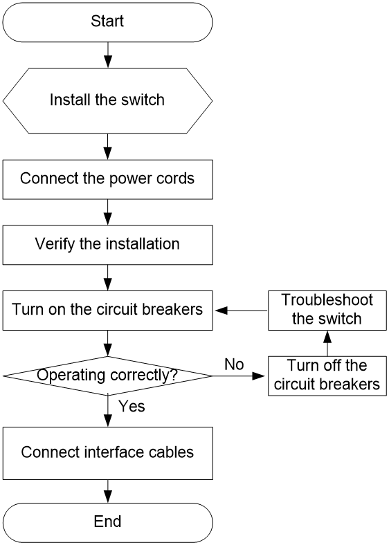
Installation flowchart
Figure2-1 Installation flowchart
Installing the switch in a tank
Tank-mounting procedures at a glance
|
|
IMPORTANT: · You can install the switch in a tank with a width of 21 inches or 23 inches. Before installation, make sure the tank is applicable to the switch. · The installation procedure in this document is only applicable to mounting the switch in an H3C tank. To mount the switch in a third-party tank, see the document provided with the tank. |
The switch comes with the mounting brackets, slide rails, and tank-mount adapters installed.
The tank-mounting method varies by tank width. When you mount the switch in a tank with a width of 23 inches, remove the slide rails and use mounting brackets and tank-mount adapters to mount the switch.
Figure2-2 Mounting the switch in a tank with a width of 23 inches
When you mount the switch in a tank with a width of 21 inches, remove the tank-mount adapters and use only mounting brackets to mount the switch.
Figure2-3 Mounting the switch in a tank with a width of 21 inches

Tank-mounting requirements
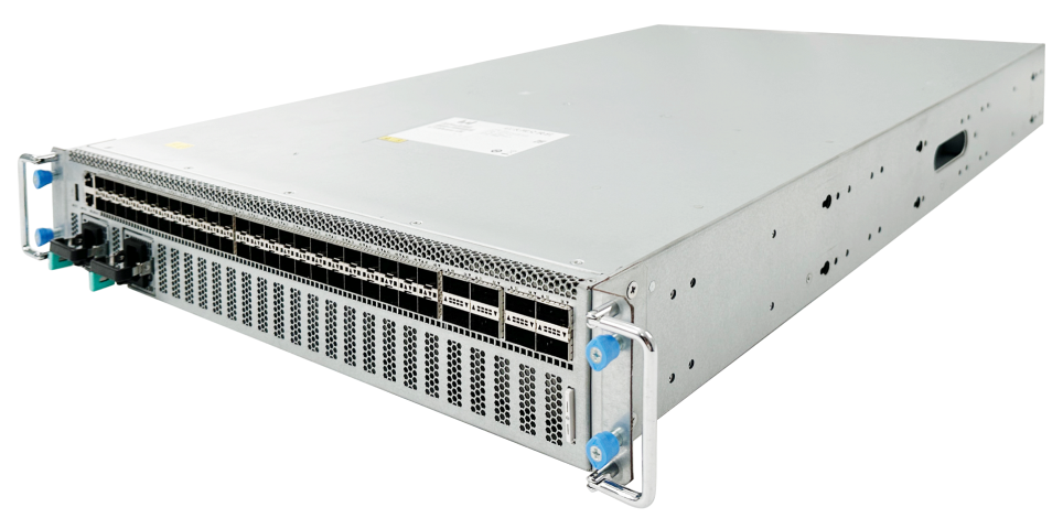
Figure2-4 S6850-56HF-IM chassis dimensions
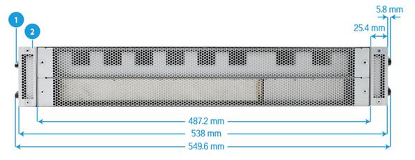
|
(1) Slide rail |
(2) Tank-mount adapter |
Table2-1 shows the required installation accessories when you install the switch in a tank with different widths.
|
Switch model |
Required installation accessories |
Tank width |
|
S6850-56HF-IM |
Mounting brackets |
21 inches |
|
Mounting brackets and tank-mount adapters |
23 inches |
For more information about tanks, see H3C Immersion Cooling System User Guide.
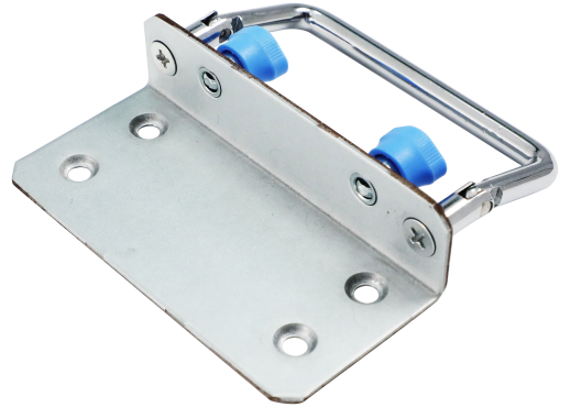
Installation accessories
Table2-2 Installation accessories
|
Switch model |
Mounting bracket |
Slide rail |
Tank-mount adapter |
|
S6850-56HF-IM |
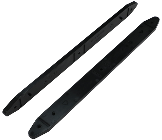
One pair of 2U high mounting brackets, provided. See Figure2-5. |
12 slide rails, provided. See Figure2-6. |
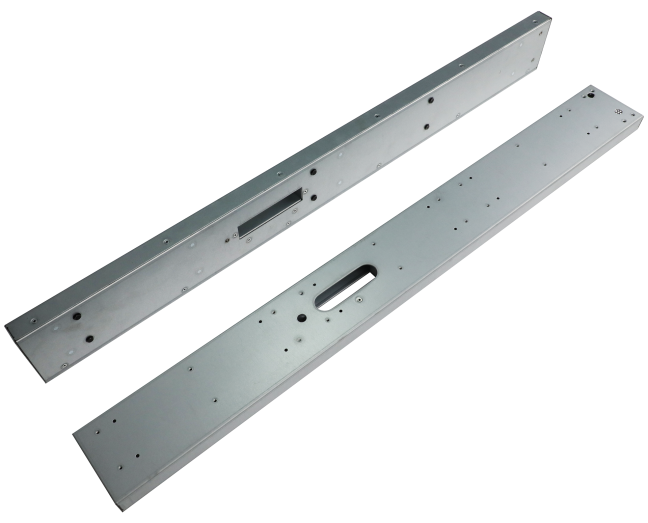
One pair of 2U high tank-mount adapters, provided. See Figure2-7. |
Removing slide rails
|
|
IMPORTANT: This section is required only when you mount the switch in a tank with a width of 23 inches. |
To remove the slide rails:
1. Face one side of the switch. Use a Phillips screwdriver to remove the three screws from a slide rail, and then remove the slide rail.
2. Repeat the procedure to remove all slide rails on both sides of the switch.
3. Put the removed slide rails and screws in a bag for future use.
Figure2-8 Removing slide rails
Removing tank-mount adapters
|
|
IMPORTANT: This section is required only when you mount the switch in a tank with a width of 21 inches. |
The removal procedure is the same for the tank-mount adapters at both sides of the switch. The following example removes a tank-mount adapter at one side of the switch.
To remove tank-mount adapters:
1. Holding a tank-mount adapter, gently push it from the port side to the power module side to disengage the pegs on the tank-mount adapter from the keyhole slots in the chassis. See Figure2-9 and Figure2-10.
2. Repeat the procedure to remove the other tank-mount adapter.
Figure2-9 Removing a tank-mount adapter (1)
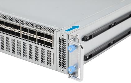
Figure2-10 Removing a tank-mount adapter (2)
Removing mounting brackets and attaching them to the chassis
|
|
IMPORTANT: This section is required only when you mount the switch in a tank with a width of 21 inches. |
To remove mounting brackets and attach them to the chassis:
1. Use a Phillips screwdriver to remove the four screws from the mounting bracket, and then remove the mounting bracket from the tank-mount adapter.
Figure2-11 Removing a mounting bracket from a tank-mount adapter

2. Repeat the procedure to remove the other mounting bracket.
3. Directly attach the mounting brackets to the chassis.
Figure2-12 Attaching the mounting brackets to the chassis
Mounting the switch in the tank
The switch comes with mounting brackets, slide rails, and tank-mount adapters installed.
To mount the switch in a tank with a width of 23 inches, make sure you have removed the slide rails. For more information, see "Removing slide rails."
To mount the switch in a tank with a width of 21 inches, make sure you have removed the tank-mount adapters, and removed mounting brackets and attached them to the chassis. For more information, see "Removing tank-mount adapters" and "Removing mounting brackets and attaching them to the chassis."
The installation slot for the switch in this document is for your reference only.
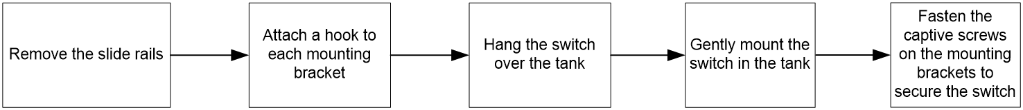
To mount the switch in the tank:
1. Wear an ESD wrist strap and make sure it makes good skin contact and is reliably grounded.
2. Select a location around the tank where a mechanical arm can reach. Make sure the location has enough space and meets the cleanliness requirements. Use two to three people to slowly stand the switch up vertically with the rear panel facing downwards.
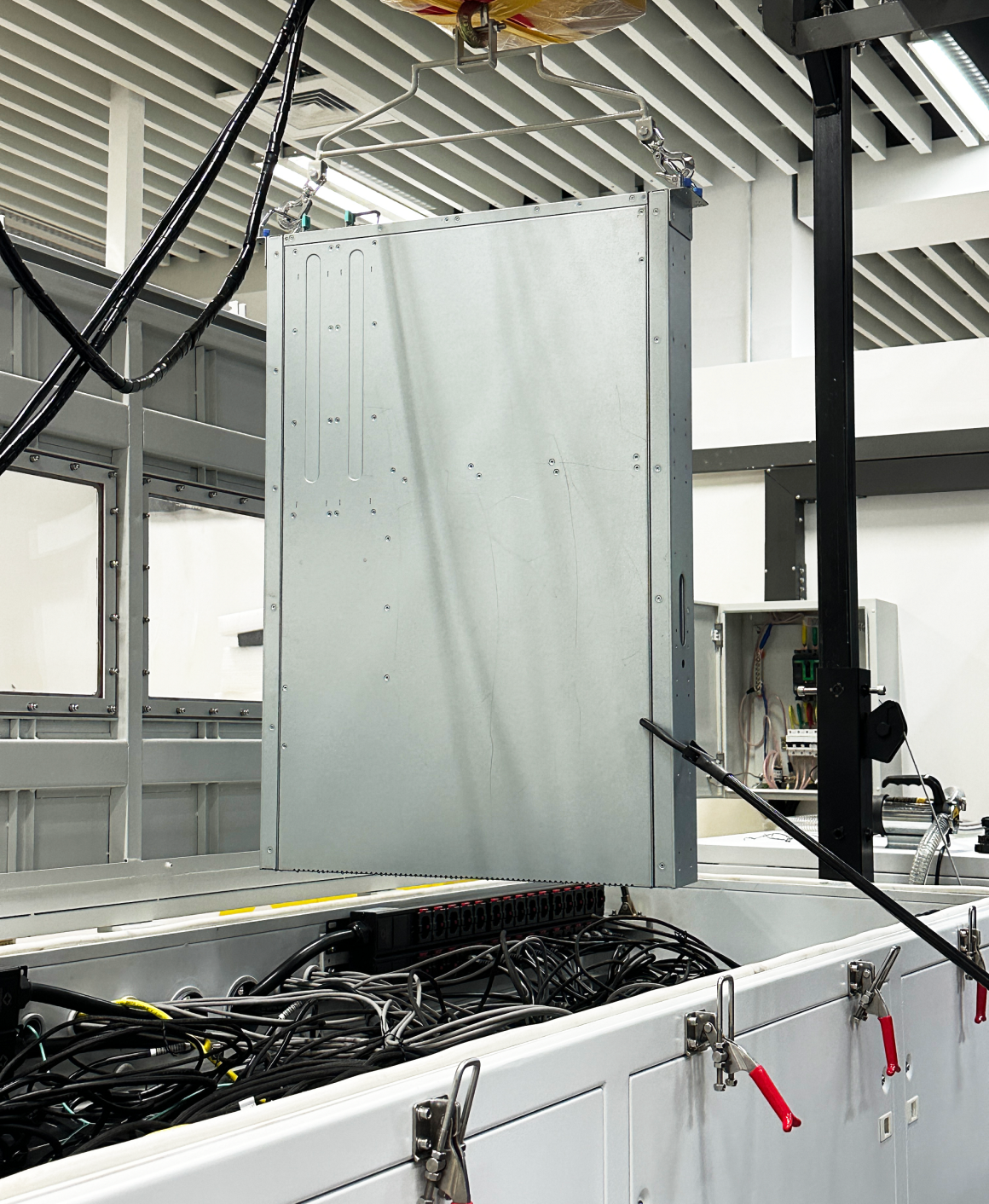
3. Attach a hook to each mounting bracket and use the mechanical arm to lift the switch until it is higher than the tank top, and then hang the switch over the tank. Keep the top surface of the switch level. See Figure2-13.
4. The switch is designed symmetrically on both sides. As a best practice, mount the switch with the power module side near the tank power strip for power cord connection.
5. Slowly lower the switch until it gets close to the installation slot. Use your hands or a brace to fine-tune its position so that it can accurately seat into the slot.
Figure2-13 Mounting the switch in the tank (1)
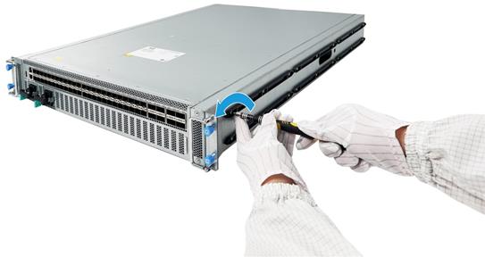
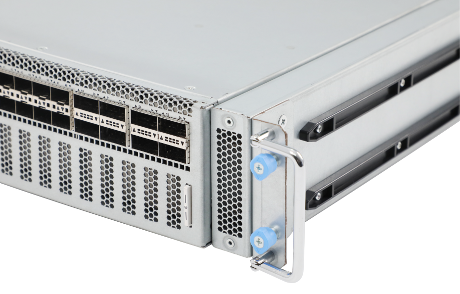
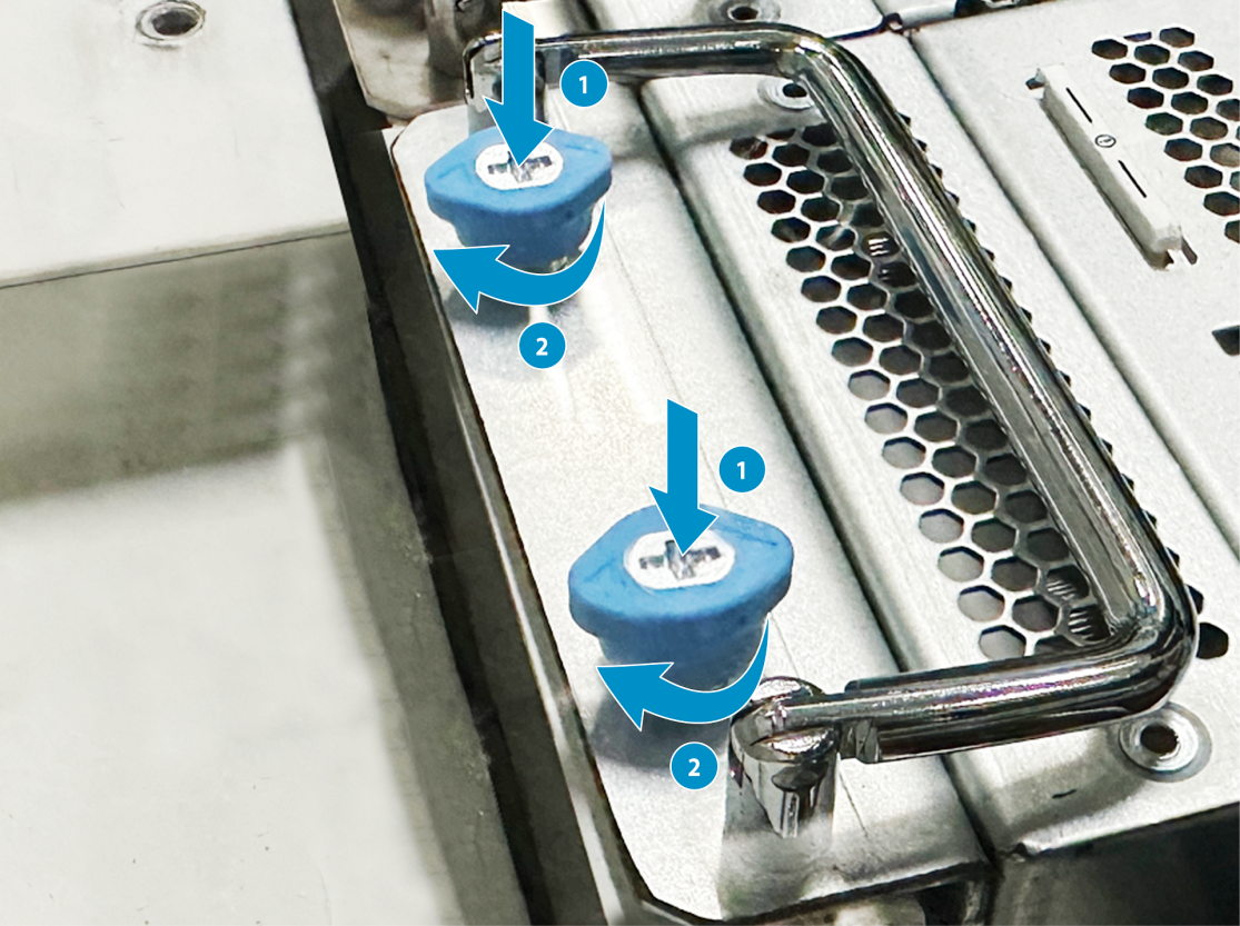
6. Remove the hooks after the switch completely seats into the slot. Use a Phillips screwdriver to fasten the captive screws to secure the switch to the slot, as shown in Figure2-14.
Figure2-14 Mounting the switch in the tank (2)
Installing/removing power modules
|
|
WARNING! · To avoid bodily injury and device damage, strictly follow the procedures in Figure2-15 and Figure2-16 to install and remove a power module. · Provide a separate circuit breaker for each power module. |
The switch comes with two power module slots each installed with a power module. You can replace a power module as required.
Figure2-15 Installation procedure
![]()
![]()
Safety guidelines
To prevent device damage and even bodily injury, follow these restrictions and guidelines when you install or remove a power module:
· Always wear an ESD wrist strap and make sure the strap makes good skin contact.
· Before installing a power module, make sure the voltage of the power source is as required by the power module, and the output voltage of the power module is as required by the device.
· Do not touch any bare cables or terminals on the power module.
· To avoid power module damage, do not open the power module. When an internal circuit or component of the power module fails, contact H3C Support.
Installing a power module
|
|
CAUTION: · Follow the forward inertia of the power module when inserting it into the chassis, and make sure the power module has firm contact with the connectors on the backplane. · To prevent damage to the connectors inside the switch chassis, insert the power module gently. If you encounter a hard resistance while inserting the power module, pull out the power module and insert it again. · To avoid burns, install a power module on the switch in a tank only when the tank is at a low temperature. · When you install a power module on the switch in a tank, wear rubber gloves to avoid direct contact with the coolant. |
|
|
IMPORTANT: You can install a power module on the switch either when the switch is already in a tank or after the switch is removed from the tank. |
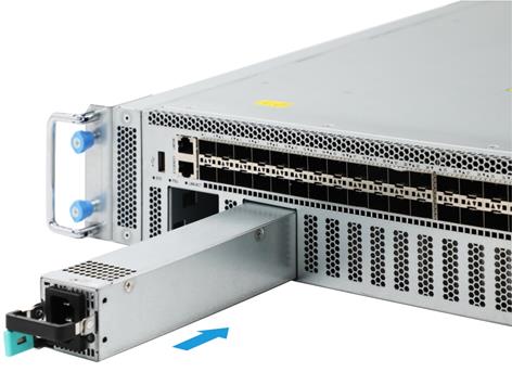
To install a power module:
1. Unpack the power module and verify that the power module model is correct.
2. Correctly orient the power module with the handle facing towards ports when it is closed. Grasping the handle of the power module with one hand and supporting its bottom with the other, slide the power module slowly along the guide rails into the slot.
2.The slot is foolproof. If you cannot insert the power module into the slot, re-orient the power module rather than use excessive force to push it in.
Figure2-17 Installing a power module
Removing a power module
|
|
CAUTION: When the switch has power modules in 1+1 redundancy mode, removing one power module does not affect the operation of the switch. When the switch has only one power module installed, removing the power module powers off the switch. |
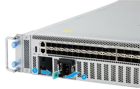
To remove a power module:
1. Remove the power cord from the power module.
2. Hold the handle on the power module with one hand, pivot the latch on the power module with your thumb, and pull the power module part way out of the slot. Supporting the power module bottom with the other hand, slowly pull the power module out of the slot.
Figure2-18 Removing a power module
3. Put the removed power module in an antistatic bag for future use.
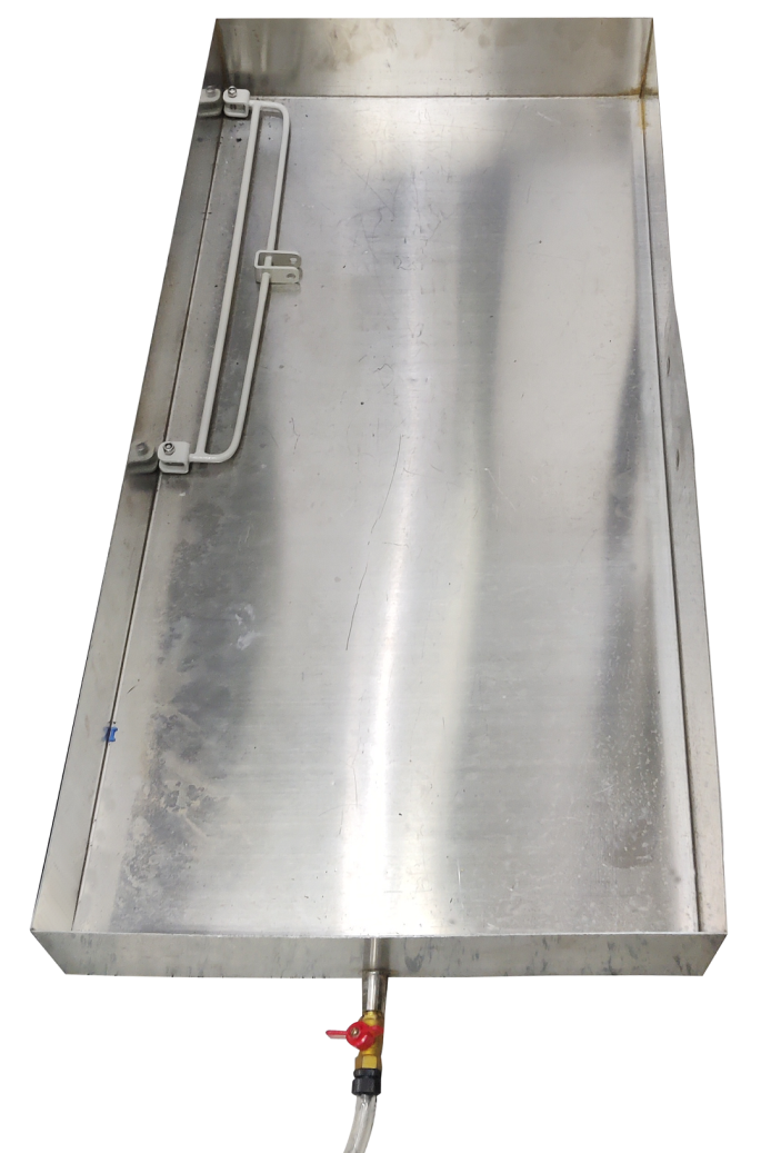
4. If you remove the power module from the switch in a tank, drain the power module in a drip tray before you put it away.
Figure2-19 Drip tray
Installing/removing liquid-cooled transceiver modules
Installing a liquid-cooled transceiver module
|
|
IMPORTANT: You must use dedicated liquid-cooled transceiver modules for the switch. |
To install a liquid-cooled transceiver module:
1. Wear rubber gloves to avoid direct contact with the coolant.
2. Remove the dust cap from the target fiber port.
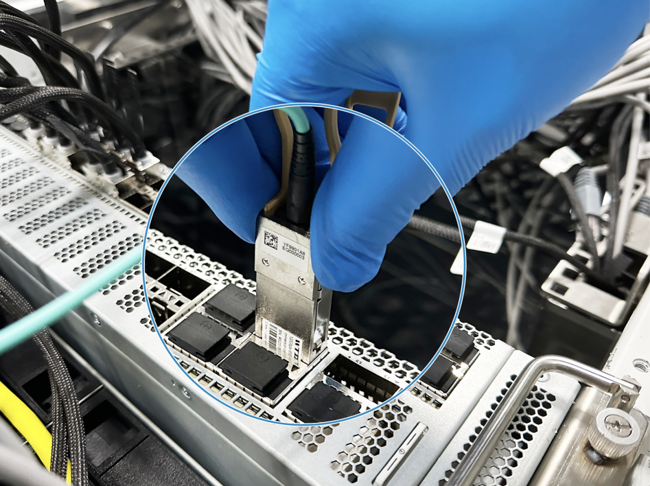
3. As shown in Figure2-20, grasp the transceiver module between your thumb and index finger and correctly orient it. Align it with the fiber port and push it gently into the port until you feel it snaps into place.
Transceiver modules and fiber ports have disorientation rejection designs. If you cannot insert a transceiver module easily into a port, the orientation might be wrong. Remove and reorient the transceiver module.
In case of limited space, you can gently push against the front face of the transceiver module instead of the two sides.
Figure2-20 Installing a liquid-cooled transceiver module (QSFP28 liquid-cooled transceiver module as an example)
|
|
NOTE: The triangular pin on a transceiver module and the hole in a fiber port function together to prevent the module from disengaging from the port. |
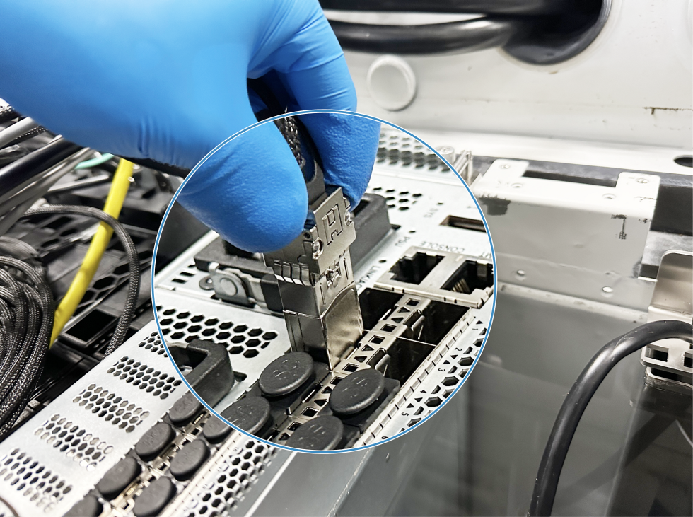
Removing a liquid-cooled transceiver module
1. Wear rubber gloves to avoid direct contact with the coolant.
2. As shown in Figure2-21, putting your forefinger into the pull ring, pull the transceiver module straight out of the fiber port.
If you use force at an angle, you can hardly pull the transceiver module out and the transceiver module or fiber port might be damaged.
To avoid damaging the pull ring, use even force to pull the transceiver module out.
Figure2-21 Removing a liquid-cooled transceiver module (QSFP28 liquid-cooled transceiver module as an example)
3. Install the dust cap for the fiber port. Drain the removed transceiver module in a drip tray before you put it away.
Connecting/disconnecting liquid-cooled cables
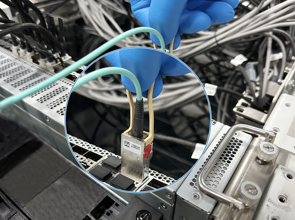
Connecting liquid-cooled cables
|
|
IMPORTANT: You must use dedicated liquid-cooled cables for the switch. |
To connect liquid-cooled cables:
1. Wear rubber gloves to avoid direct contact with the coolant.
2. Remove the dust cap from the target fiber port.
3. As shown in Figure2-22, correctly orient the transceiver module at one end of the cable and gently insert the module into the target port until it snaps into place.
Transceiver modules and fiber ports have disorientation rejection designs. If you cannot insert a transceiver module easily into a port, the orientation might be wrong. Remove and reorient the transceiver module.
Figure2-22 Connecting a liquid-cooled cable (SFP28 cable as an example)
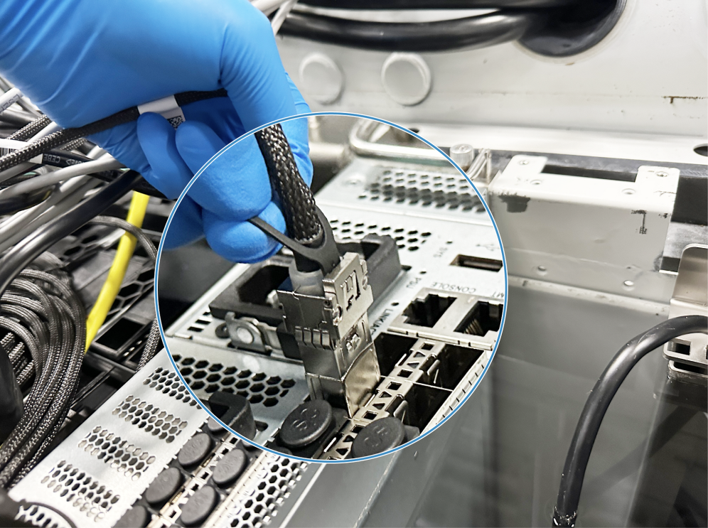
Disconnecting liquid-cooled cables
1. Wear rubber gloves to avoid direct contact with the coolant.
2. As shown in Figure2-23, putting your forefinger into the pull ring and holding the cable, pull the cable straight out of the fiber port.
If you use force at an angle, you can hardly pull the cable out and the cable or fiber port might be damaged.
To avoid damaging the pull ring, use even force to pull the cable out.
Figure2-23 Disconnecting a liquid-cooled cable (SFP28 cable as an example)
3. Install the dust cap for the fiber port. Drain the disconnected cable in a drip tray before you put it away.
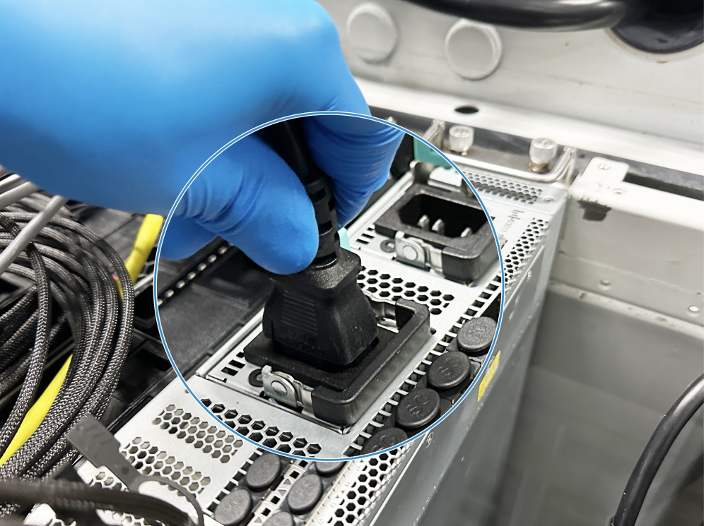
Connecting the power cords
|
|
WARNING! Provide a circuit breaker for each power input. When you connect a power cord, make sure the circuit breaker is switched off. |
1. Insert the female connector of the AC power cord supplied with the power module into the power receptacle on the power module.
2. Connect the other end of the power cord to an external AC power source.
Figure2-24 Connecting an AC power cord
Verifying the installation
After you complete the installation, verify the following information:
· The power source is as required by the switch.
· The power cord is correctly connected.
· All the interface cables are cabled indoors. The switch does not support outdoor cable routing.
3 Accessing the switch for the first time
Connecting the switch to a configuration terminal
You can access the switch through the serial console port.
In Figure3-1, the switch is connected to a configuration terminal (PC as an example) from the serial console port.
Figure3-1 Connecting the serial console port to a terminal
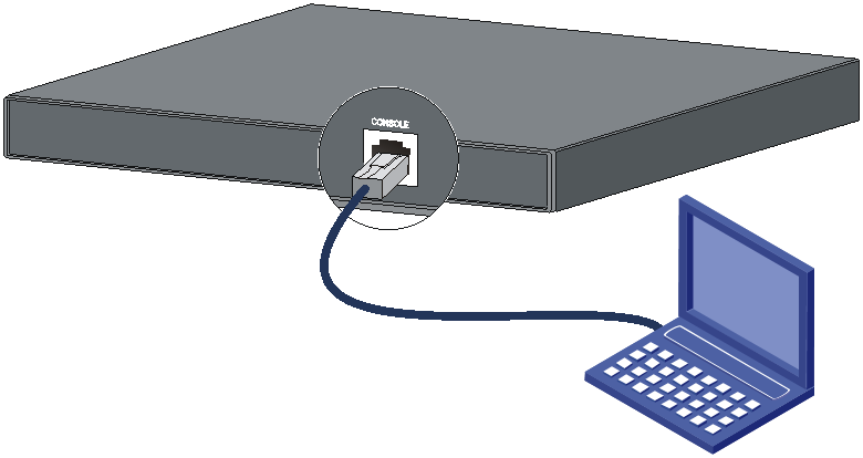
As shown in Table3-1, two types of console cables can be used for connecting the switch to a configuration terminal. The switch is not provided with a serial console cable.
Table3-1 Connection methods and console cables
|
Connection method |
Console cable type |
Configuration terminal-side connector |
Switch-side connector |
|
Using the serial console port for connection |
DB9-to-RJ45 console cable |
DB-9 female connector |
RJ-45 connector |
|
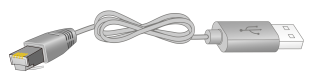
USB-to-RJ45 console cable |
USB connector |
RJ-45 connector |
The signal pinout for the RJ-45 connector of a serial console cable varies by vendor. To avoid abnormal configuration terminal display, use a serial console cable provided by H3C. For more information, see Table3-2. To prepare a serial console cable yourself, make sure the signal pinout for the RJ-45 connector is the same as that shown in Table3-3.
|
Console cable type |
Console cable view |
|
DB9-to-RJ45 console cable |
|
|
USB-to-RJ45 console cable |
|

Connecting the console cable
Connecting a DB9-to-RJ45 console cable
A serial console cable is an 8-core cable, with a crimped RJ-45 connector at one end for connecting to the serial console port of the switch, and a DB-9 female connector at the other end for connecting to the serial port on the console terminal.
Figure3-2 Serial console cable
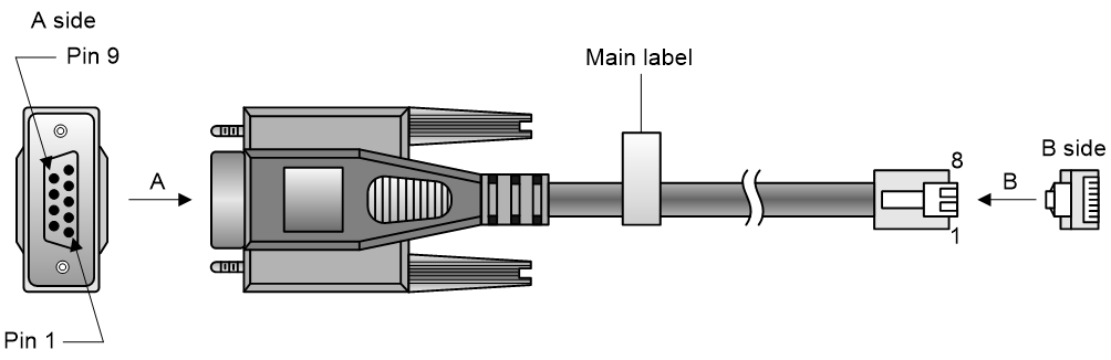
Table3-3 Console port signaling and pinout
|
RJ-45 |
Signal |
DB-9 |
Signal |
|
1 |
RTS |
8 |
CTS |
|
2 |
DTR |
6 |
DSR |
|
3 |
TXD |
2 |
RXD |
|
4 |
SG |
5 |
SG |
|
5 |
SG |
5 |
SG |
|
6 |
RXD |
3 |
TXD |
|
7 |
DSR |
4 |
DTR |
|
8 |
CTS |
7 |
RTS |
To connect a configuration terminal (for example, a PC) to the switch through a DB9-to-RJ45 console cable:
1. Plug the DB-9 female connector of the DB9-to-RJ45 console cable to the serial port on the PC.
2. Connect the RJ-45 connector to the serial console port on the switch.
|
|
NOTE: · Identify the mark on the console port and make sure you are connecting to the correct port. · The serial ports on PCs do not support hot swapping. To connect a PC to an operating switch, first connect the PC end. To disconnect a PC from an operating switch, first disconnect the switch end. |
Connecting a USB-to-RJ45 console cable
|
|
IMPORTANT: · To use a USB-to-RJ45 console cable to connect the switch to a configuration terminal, first download and install the USB-to-RJ45 console driver on the configuration terminal and then connect the USB-to-RJ45 console cable to the configuration terminal. · If you have connected a USB-to-RJ45 console cable to the configuration terminal before driver installation, you must remove and reconnect the USB-to-RJ45 console cable to the configuration terminal. |
For information about the signal pinout for the RJ-45 connector of a USB-to-RJ45 console cable, see Table3-3.
The following procedure describes how to install the driver on the Windows system. To install the driver on other operating systems, see the installation guide in the driver compression package named by the corresponding operating system.
To connect the switch to the configuration terminal through a USB-to-RJ45 console cable:
1. Click the following link, or copy it to the address bar on your browser and download the USB-to-RJ45 console driver.
http://www.h3c.com/en/home/USB_to_RJ45_Console/
2. View the TXT file Read me in the Windows folder to check whether the Windows system of the configuration terminal supports the driver.
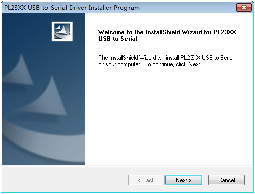
3. If the Windows system supports the driver, install PL23XX-M_LogoDriver_Setup_v200_20190815.exe.
4. Click Next on the welcome page of the driver installation wizard.
Figure3-3 Driver installation wizard
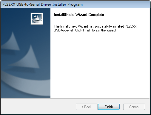
5. Click Finish after the drive installation is completed.
Figure3-4 Finishing the driver installation
6. Connect the standard USB connector of the cable to the USB port of the configuration terminal.
7. Connect the RJ-45 connector of the cable to the console port of the switch.
Setting terminal parameters
To configure and manage the switch through the console port, you must run a terminal emulator program, TeraTermPro or PuTTY, on your configuration terminal. You can use the emulator program to connect a network device, a Telnet site, or an SSH site. For more information about the terminal emulator programs, see the user guides for these programs
The following are the required terminal settings:
· Bits per second—9600.
· Data bits—8.
· Stop bits—1.
· Parity—None.
· Flow control—None.
Powering on the switch
1. Before powering on the switch, verify that the following conditions are met:
¡ The power cords are connected correctly.
¡ The input power voltage is as required by the switch.
¡ The console cable is connected correctly.
¡ The configuration terminal (a PC, for example) has started, and its serial port settings are consistent with the console port settings on the switch.
2. Power on the switch.
During the startup process, you can access BootWare menus to perform tasks such as software upgrade and file management. The BootWare interface and menu options vary by software version. For more information about BootWare menu options, see the software-matching release notes for the device.
3. After the startup completes, you can access the CLI to configure the switch.
For more information about the configuration commands and CLI, see H3C S6805 & S6825 & S6850 & S9850 Switch Series Configuration Guides and H3C S6805 & S6825 & S6850 & S9850 Switch Series Command References.
4 Setting up an IRF fabric
You can use H3C IRF technology to connect and virtualize multiple S6850-56HF-IM switches into a large virtual switch called an "IRF fabric" for flattened network topology, and high availability, scalability, and manageability.
IRF fabric setup flowchart
Figure4-1 IRF fabric setup flowchart
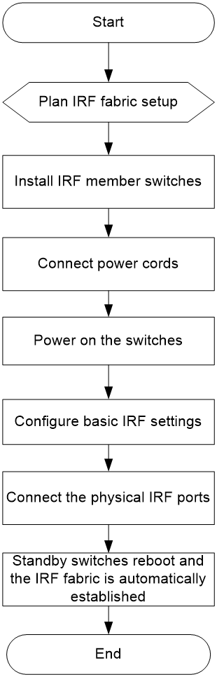
To set up an IRF fabric:
|
Step |
Description |
|
1. Plan IRF fabric setup. |
Plan the installation site and IRF fabric setup parameters: · Planning IRF fabric size and the installation site · Identifying the master switch and planning IRF member IDs · Planning IRF topology and connections |
|
2. Install IRF member switches. |
|
|
3. Connect the power cords. |
See "Connecting the power cords." |
|
4. Power on the switches. |
N/A |
|
5. Configure basic IRF settings. |
See IRF configuration in H3C S6805 & S6825 & S6850 & S9850 Switch Series Virtual Technologies Configuration Guide. |
|
6. Connect the physical IRF ports. |
Connect the physical IRF ports on switches. Use QSFP28 transceiver modules and fibers for connections. All switches except the master switch automatically reboot, and the IRF fabric is established. |
Planning IRF fabric setup
This section describes issues that an IRF fabric setup plan must cover.
Planning IRF fabric size and the installation site
Determine the number of required IRF member switches, depending on the user density and upstream bandwidth requirements. The switching capacity of an IRF fabric equals the total switching capacities of all member switches.
An S6850-56HF-IM switch can set up an IRF fabric with switches from the S6850 switch series.
Reserve sufficient space in the tank for installation of the devices.
As your business grows, you can add member switches into the IRF fabric to increase the switching capacity without any topology change or replacement.
Identifying the master switch and planning IRF member IDs
Determine which switch you want to use as the master for managing all member switches in the IRF fabric. An IRF fabric has only one master switch. You configure and manage all member switches in the IRF fabric at the command line interface of the master switch.
|
|
NOTE: IRF member switches will automatically elect a master. You can affect the election result by assigning a high member priority to the intended master switch. For more information about master election, see IRF configuration in H3C S6805 & S6825 & S6850 & S9850 Switch Series Virtual Technologies Configuration Guide. |
Prepare an IRF member ID assignment scheme. An IRF fabric uses member IDs to uniquely identify and manage its members, and you must assign each IRF member switch a unique member ID.
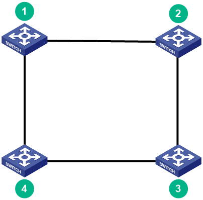
Planning IRF topology and connections
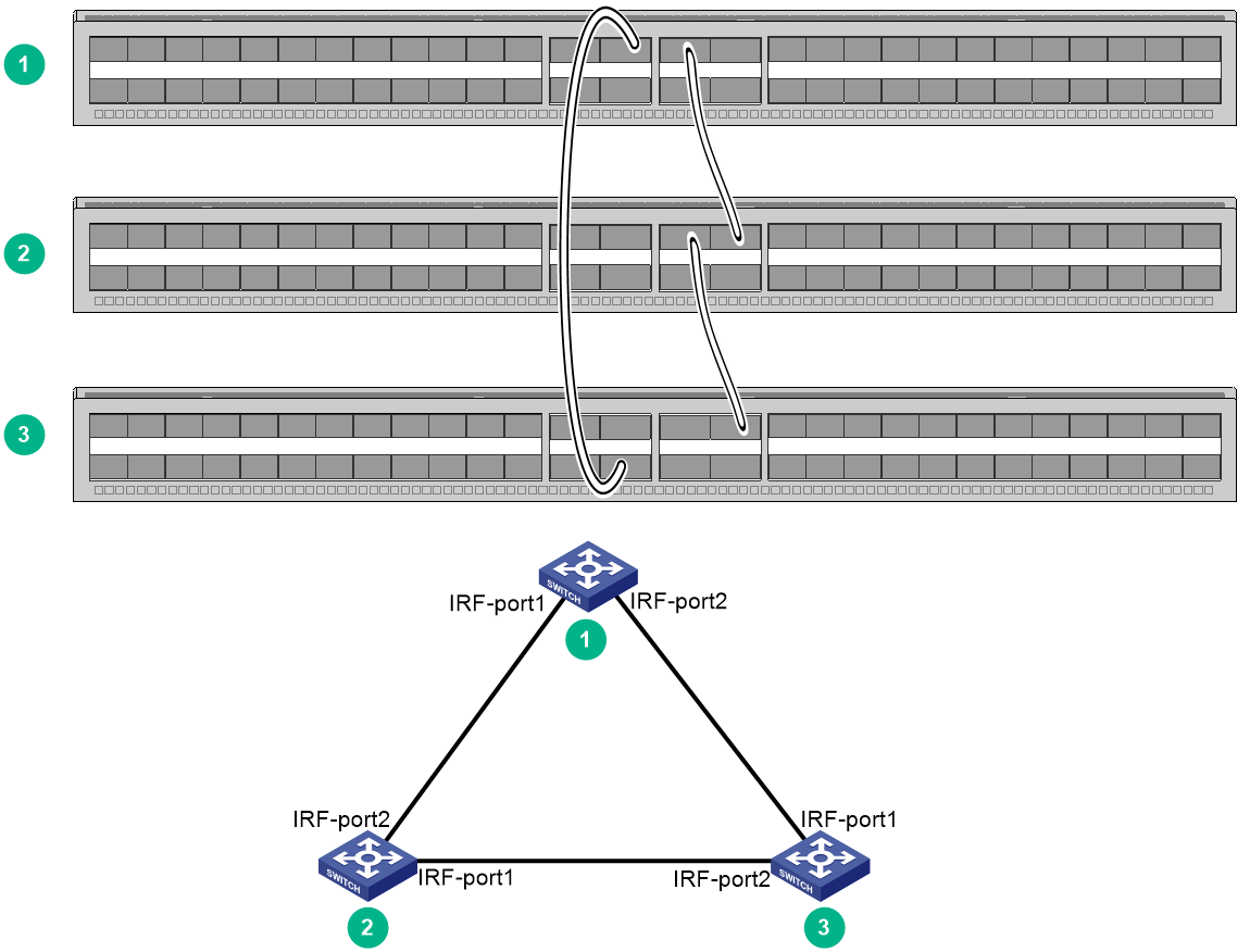
You can create an IRF fabric in daisy chain topology, or more reliably, ring topology. In ring topology, the failure of one IRF link does not cause the IRF fabric to split as in daisy chain topology. Rather, the IRF fabric changes to a daisy chain topology without interrupting network services.
You connect the IRF member switches through IRF ports, the logical interfaces for the connections between IRF member switches. Each IRF member switch has two IRF ports: IRF-port 1 and IRF-port 2. To use an IRF port, you must bind a minimum of one physical port to it.
When connecting two neighboring IRF member switches, you must connect the physical ports of IRF-port 1 on one switch to the physical ports of IRF-port 2 on the other switch.
The IRF port connections in the two figures are for illustration only, and more connection methods are available.
Figure4-2 IRF fabric in daisy chain topology
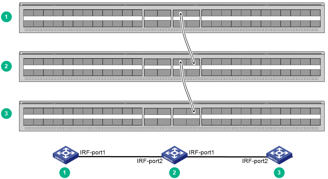
Figure4-3 IRF fabric in ring topology
You can set up IRF links between S6850-56HF-IM switches by using a QSFP28 module and fiber to connect QSFP28 ports for a 100-GE IRF physical connection.
You can bind several ports to an IRF port for increased bandwidth and availability.
Identifying physical IRF ports on the member switches
Identify the physical ports for IRF connections on the member switches according to your topology and connection scheme.
All the QSFP28 ports on the switch can be used for IRF connections.
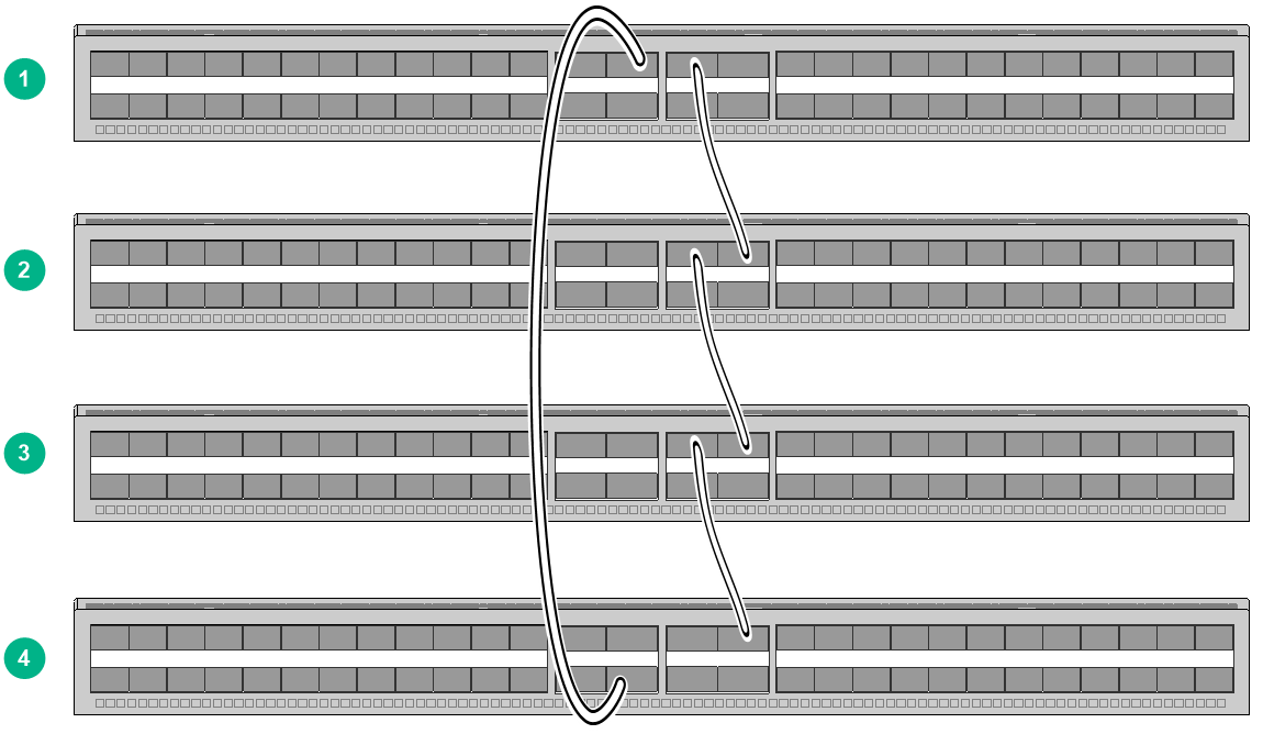
Planning the cabling scheme
You can use QSFP28 transceiver modules and fibers to connect the S6850-56HF-IM switches for IRF connections.
The following subsections describe several IRF connection schemes by using the QSFP28 transceiver modules and fibers. As a best practice, use the ring topology for IRF connections.
Figure4-4 shows an example for connecting four IRF member switches. The switches in the ring topology (see Figure4-5) are connected in the same order.
Figure4-4 Connecting the switches
Configuring basic IRF settings
After you install the IRF member switches, power on the switches, and log in to each IRF member switch (see H3C S6805 & S6825 & S6850 & S9850 Switch Series Fundamentals Configuration Guide) to configure their member IDs, member priorities, and IRF port bindings.
Follow these guidelines when you configure the switches:
· Assign the master switch higher member priority than any other switch.
· Bind physical ports to IRF port 1 on one switch and to IRF port 2 on the other switch. You perform IRF port binding before or after connecting IRF physical ports depending on the software release.
· Execute the display irf configuration command to verify the basic IRF settings.
For more information about configuring basic IRF settings, see H3C S6805 & S6825 & S6850 & S9850 Switch Series Virtual Technologies Configuration Guide.
Connecting the physical IRF ports
Use transceiver modules and fibers or cables to connect the IRF member switches as planned.
Accessing the IRF fabric to verify the configuration
To verify the basic functionality of the IRF fabric after you finish configuring basic IRF settings and connecting IRF ports:
1. Log in to the IRF fabric through the console port of any member switch.
2. Create a Layer 3 interface, assign it an IP address, and make sure the IRF fabric and the remote network management station can reach each other.
3. Use Telnet or SNMP to access the IRF fabric from the network management station. (See H3C S6805 & S6825 & S6850 & S9850 Switch Series Fundamentals Configuration Guide.)
4. Verify that you can manage all member switches as if they were one node.
5. Display the running status of the IRF fabric by using the commands in Table4-1.
Table4-1 Displaying and maintaining IRF configuration and running status
|
Task |
Command |
|
Display information about the IRF fabric. |
display irf |
|
Display all members' IRF configurations. |
display irf configuration |
|
Display IRF fabric topology information. |
display irf topology |
|
|
NOTE: To avoid IP address collision and network problems, configure at least one multi-active detection (MAD) mechanism to detect the presence of multiple identical IRF fabrics and handle collisions. For more information about MAD detection, see H3C S6805 & S6825 & S6850 & S9850 Switch Series Virtual Technologies Configuration Guide. |
5 Setting up an M-LAG system
Multichassis Link Aggregation (M-LAG) virtualizes two physical devices into one system through multichassis link aggregation to provide device-class high availability and load sharing.
Compared to IRF, M-LAG offers higher network reliability and shorter service interruption during upgrade.
You cannot configure IRF and M-LAG on the same network.
|
|
IMPORTANT: The device supports both the M-LAG set and DRNI set of command keywords in the CLI by default. The two sets of commands are consistent in the service configuration methods, functions, and output, with only differences in the command keywords. For the differences in the command keywords, see M-LAG configuration in Layer 2—LAN Switching Configuration Guide of H3C S6805 & S6825 & S6850 & S9850 Switch Series Configuration Guides-Release 671x. |
M-LAG system setup flowchart
Figure5-1 M-LAG system setup flowchart
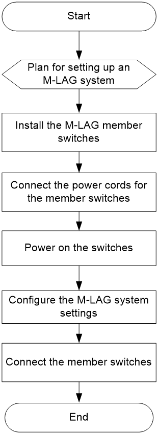
To set up an M-LAG system:
|
Step |
Description |
|
1. Plan for setting up the M-LAG system. |
Plan for setting up the M-LAG system based on the network and device conditions: · Determine the installation locations of the switches. · Reserve physical ports for M-LAG connections. · Plan the cable connection scheme. For more information, see "Planning for setting up an M-LAG system." |
|
2. Install M-LAG member switches. |
|
|
3. Connect the power cords for the member switches. |
See "Connecting the power cords." |
|
4. Power on the switches. |
N/A |
|
5. Configure the M-LAG system settings. |
For detailed information about M-LAG, see M-LAG configuration in H3C S6805 & S6825 & S6850 & S9850 Switch Series Layer 2—LAN Switching Configuration Guide. |
|
6. Connect the member switches. |
Select cables or transceiver modules and optical fibers matching the rate of the physical ports of the peer link and keepalive link for connection. |
Planning for setting up an M-LAG system
Determining device installation locations
An M-LAG system can be set up with only two devices. Reserve sufficient space in the tank for installation of the devices.
Reserving physical ports for M-LAG connection
To set up an M-LAG system, you must establish a peer link and a keepalive link between the two devices.
The M-LAG member devices exchange protocol packets and transmit data traffic over the peer link. An M-LAG system has only one peer link. You can create a peer-link interface on each M-LAG member device, and the link between the two peer-link interfaces is the peer link.
The M-LAG member devices exchange keepalive packets over the keepalive link to detect multi-active collisions when the peer link is down.
Peer link
In addition to protocol packets, the peer link also transmits data packets between the M-LAG member devices when an uplink fails. When you set up the peer link, follow these restrictions and guidelines:
· Assign at least two physical interfaces to the aggregation group for the peer-link interface.
· The member ports in the aggregation group for the peer-link interface must have the same speed.
· If an M-LAG system is attached to a large number of servers by using non-M-LAG interfaces, take the size of the traffic sent among those servers into account when you determine the bandwidth of the peer link.
Keepalive link
As a best practice, establish a dedicated direct link between two M-LAG member devices as a keepalive link. Do not use the keepalive link for any other purposes. Make sure the M-LAG member devices have Layer 2 and Layer 3 connectivity to each other over the keepalive link.
You can use management Ethernet interfaces, Layer 3 Ethernet interfaces, Layer 3 aggregate interfaces, or interfaces with a VPN instance bound to set up the keepalive link.
As a best practice, do not use VLAN interfaces for keepalive link setup. If you have to use VLAN interfaces, remove the peer-link interfaces from the related VLANs to avoid loops.
Planning the cable connection scheme
Select cables or transceiver modules and optical fibers matching the rate of physical ports of the peer link and the keepalive link for connection.
Cables are short but with high performance and stability, suitable for short-distance connections in the equipment room. Transceiver modules and optical fibers can be combined flexibly and is suitable for longer distance connections.
For information about the transceiver modules and cables supported by the switch, see H3C S6850-56HF-IM Immersion-Cooled Switch Hardware Information and Specifications.
This following section describes several cable connection schemes that use 100G physical ports for the peer link connection and 25G physical ports for the keepalive link connection, with matching cables or transceiver module and optical fibers.
|
|
NOTE: The physical port locations in the following figures are for illustration only. |
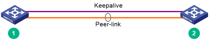
Figure5-2 Connecting two M-LAG member devices
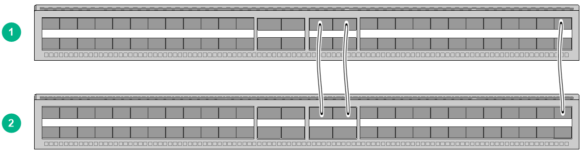
Figure5-3 Connection topology of two M-LAG member devices
Configuring the M-LAG system settings
After you install the M-LAG member switches, start and log in to each member switch to configure basic M-LAG system settings, including:
· M-LAG system MAC address.
· M-LAG system ID.
· M-LAG system priority.
· Peer-link interface settings.
· Keepalive parameters.
For information about logging in to the switch, see H3C S6805 & S6825 & S6850 & S9850 Switch Series Fundamentals Configuration Guide.
For information about configuring the M-LAG system settings, see M-LAG configuration in H3C S6805 & S6825 & S6850 & S9850 Ethernet Switch Series Layer 2—LAN Switching Configuration Guide.
Restrictions and guidelines
You can set up an M-LAG system with only two member devices. For the M-LAG member devices to be identified as a single M-LAG system, you must configure the same M-LAG system MAC address and M-LAG system priority for them. To distinguish between the two member devices, assign them different M-LAG system IDs.
Make sure the MAC address of the M-LAG system is unique.
For correct packet forwarding, delete M-LAG configuration from an M-LAG member device if it leaves its M-LAG system.
When you bulk shut down physical interfaces on an M-LAG member device for service changes or hardware replacement, shut down the physical interfaces used for keepalive detection prior to the physical member ports of the peer-link interface. If you fail to do so, link flapping will occur on the member ports of M-LAG interfaces.
You must configure the keepalive link interfaces (including physical ports and logical interfaces) as M-LAG reserved interfaces. This ensures that these interfaces will not be MAD down when the peer link fails.
For more configuration restrictions and guidelines and typical configuration examples for the M-LAG system, see H3C Data Center Switches M-LAG Configuration Guide.
Connecting the M-LAG member switches
|
|
CAUTION: Wear an ESD wrist strap when you connect the M-LAG member switches. Make sure the strap makes good skin contact and is reliably grounded. |
Connect the M-LAG member switches based on the network topology and cable connection scheme. For the installation method and restrictions and guidelines for connecting cables or transceiver modules and optical fibers, see the installation guide for them.
Verifying the configuration
To verify the running status of the M-LAG system:
1. Create a Layer 3 interface on a member device, assign it an IP address, and make sure the device and the remote network management station can reach each other.
2. Use Telnet or SNMP to access the device remotely. For more information, see H3C S6805 & S6825 & S6850 & S9850 Switch Series Fundamentals Configuration Guide.
3. Display the running status of the M-LAG system by using the display commands in any view.
Table5-1 Displaying and maintaining M-LAG system configuration and running status
|
Task |
Command |
|
Display M-LAG member device role information. |
display m-lag role |
|
Display M-LAG interface summary information. |
display m-lag summary |
|
Display M-LAG system information. |
display m-lag system |
|
Display detailed information about M-LAG interfaces. |
display m-lag verbose [ interface interface-number ] |
|
|
CAUTION: · In an M-LAG system, all management Ethernet ports on the primary and secondary devices are available for use. From the perspective of the network management system, the two devices in the M-LAG system are independent and you must log in and manage them separately. · To prevent network failures caused by M-LAG system splitting, configure HA after the M-LAG system is set up. For more information, see H3C Data Center Switches M-LAG Configuration Guide. |
6 Maintenance and troubleshooting
Power module failure
Symptom
The power module status LED on the power module is not steady green (active state) or flashing green (standby state).
For more information about the LED on a power module, see H3C S6850-56HF-IM Immersion-Cooled Switch Hardware Information and Specifications.
Solution
1. Verify that the power cord is connectedly correctly.
2. Verify that the power source is as required by the switch.
3. If the issue persists, contact H3C Support.
To replace a power module, see "Installing/removing power modules."
Configuration terminal display issues
No display on the configuration terminal
Symptom
The switch starts up but the configuration terminal does not have any display.
Solution
To resolve the issue:
1. Verify that the power supply is supplying power correctly to the switch.
2. Verify that the console cable is connected correctly.
3. Verify that the console cable is in good condition.
4. Verify that the terminal settings are correct.
5. If the issue persists, contact H3C Support.
Garbled display on the configuration terminal
Symptom
The configuration terminal displays garbled texts.
Solution
To resolve the issue:
1. Verify that the configuration terminal settings are correct, as follows:
¡ Baud rate—9600.
¡ Data bits—8.
¡ Stop bits—1.
¡ Parity—None.
¡ Flow control—None.
2. If the issue persists, contact H3C Support.
