- Table of Contents
- Related Documents
-
| Title | Size | Download |
|---|---|---|
| 01-Installation Guide | 4.23 MB |
Examining the installation site
Installing the switch in a liquid-cooled rack
Rack-mounting procedures at a glance
Mounting brackets, chassis rails, and grounding cable installation positions
Attaching the mounting brackets and chassis rails to the chassis
Connecting the grounding cable to the chassis
Attaching the slide rails to the rack
Mounting the switch in the rack
Installing/removing power modules
Connecting/disconnecting liquid-cooled pipes
Connecting liquid-cooled pipes
Disconnecting liquid-cooled pipes
3 Accessing the switch for the first time
Connecting the switch to a configuration terminal
Connecting a DB9-to-RJ45 console cable
Connecting a USB-to-RJ45 console cable
Planning IRF fabric size and the installation site
Identifying the master switch and planning IRF member IDs
Planning IRF topology and connections
Identifying physical IRF ports on the member switches
Configuring basic IRF settings
Connecting the physical IRF ports
Accessing the IRF fabric to verify the configuration
Planning for setting up an M-LAG system
Determining device installation locations
Reserving physical ports for M-LAG connection
Planning the cable connection scheme
Configuring the M-LAG system settings
Connecting the M-LAG member switches
6 Maintenance and troubleshooting
Configuration terminal display issues
No display on the configuration terminal
Garbled display on the configuration terminal
1 Preparing for installation
This document is applicable to the H3C S6850-56HF-CP cold plate-based liquid-cooled Ethernet switch (product code LS-6850-56HF-CP).
Safety recommendations
To avoid bodily injury or damage to the switch, read the following safety recommendations carefully before working with the switch. Note that the recommendations do not cover every possible hazardous condition.
· Before cleaning the switch, remove all power cords from the switch. Do not clean the switch with wet cloth or liquid.
· Do not place the switch near water or in a damp environment. Prevent water or moisture from entering the switch chassis.
· Do not place the switch on an unstable case or desk.
· Ensure adequate ventilation for the switch and keep the protective vents of the switch unblocked.
· Make sure the power source voltage meets the requirements of the switch.
· To avoid electrical shocks, do not open the chassis while the switch is operating. As a best practice, do not open the chassis even if the switch is powered off.
· To avoid ESD damage, always wear an ESD wrist strap when you replace a power module, fan tray, or expansion module.
Examining the installation site
Make sure the installation site meet the requirements of temperature, cleanliness, and corrosive gas limit. For more information about the installation site requirements, see H3C Cold Plate-Based Liquid-Cooling System User Guide.
Installation tools
No installation tools are provided with the switch. Prepare the following tools yourself:
· Phillips screwdriver.
· ESD wrist strap.
· Marker.
2 Installing the switch
|
|
CAUTION: Keep the tamper-proof seal on a mounting screw on the chassis cover intact, and if you want to open the chassis, contact H3C for permission. Otherwise, H3C shall not be liable for any consequence caused thereby. |
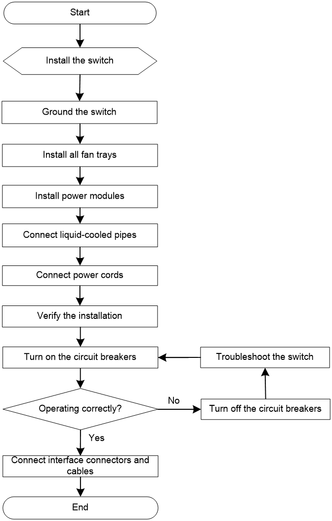
Installation flowchart
Figure2-1 Installation flowchart
Installing the switch in a liquid-cooled rack
Rack-mounting procedures at a glance
Figure2-2 Rack-mounting procedure
![]()
Rack-mounting requirements
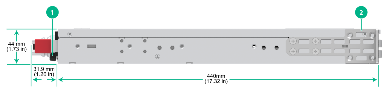
Figure2-3 LS-6850-56HF-CP chassis dimensions (mounting brackets installed at the port side)
|
(1) Power module handle |
(2) Mounting bracket |
Figure2-4 LS-6850-56HF-CP chassis dimensions (mounting brackets installed at the power module side)

|
(1) Power module handle |
(2) Mounting bracket |
|
|
NOTE: For more information about the liquid-cooled rack, see H3C Cold Plate-Based Liquid-Cooling System User Guide. |
Table2-1 Distance requirements between the front and rear rack posts
|
Switch model |
Installation method |
Distance between the front and rear rack posts |
Rack requirements |
|
LS-6850-56HF-CP |
Extended mounting brackets and short slide rails |
314 to 720 mm (12.36 to 28.35 in, mounting brackets installed at the port side) |
A minimum of 800 mm (31.50 in) in depth (recommended). · A minimum of 130 mm (5.12 in) between the front rack post and the front door. · A minimum of 650 mm (25.59 in) between the front rack post and the rear door. To mount the switch in a liquid-cooled rack, use extended mounting brackets and short slide rails. |
|
Mounting brackets and long slide rails (provided) |
692 to 793 mm (27.24 to 31.22 in, mounting brackets installed at the port side) |
||
|
692 to 728 mm (27.24 to 28.66 in, mounting brackets installed at the power module side) |
|||
|
Mounting brackets and super-short slide rails (optional, chassis rails not reaching out of the chassis) |
401 to 523 mm (15.79 to 20.59 in, mounting brackets installed at the port side) |
||
|
Mounting brackets and super-short slide rails (optional, chassis rails reaching out of the chassis) |
439 to 630 mm (17.28 to 24.80 in, mounting brackets installed at the port side) |
||
|
439 to 547 mm (17.28 to 21.54 in, mounting brackets installed at the power module side) |
Installation accessories
Table2-2 Installation accessories
|
Switch model |
Mounting brackets |
Rack mounting rail kit |
|
S6850-56HF-CP |
One pair of extended mounting brackets. See Figure2-5. The mounting bracket with a round hole in the narrow flange supports hanging a fixed asset tag. |
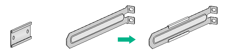
1U high, including one pair of short slide rails and one pair of chassis rails (provided). See Figure2-8. |
|
1U high, one pair. See Figure2-6. The mounting bracket with a round hole in the narrow flange supports hanging a fixed asset tag. |
1U high, including one pair of long slide rails and one pair of chassis rails (provided). See Figure2-7. |
|
|
1U high, including one pair of super-short slide rails and one pair of chassis rails (optional). See Figure2-9. |
Figure2-5 Extended mounting brackets
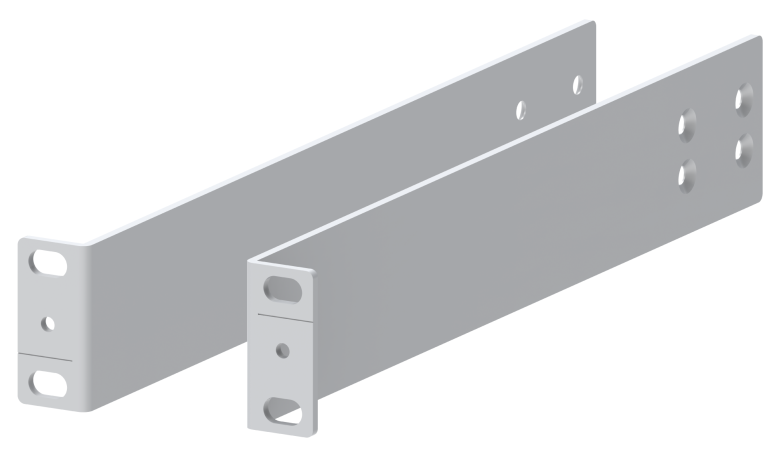
Figure2-6 1U mounting brackets

Figure2-7 1U long slide rail and chassis rail

|
(1) Chassis rail |
(2) Long slide rail |
Figure2-8 1U short slide rail and chassis rail
|
(1) Chassis rail |
(2) Short slide rail |
Figure2-9 1U super-short slide rail and chassis rail

|
(1) Chassis rail |
(2) Super-short slide rail |
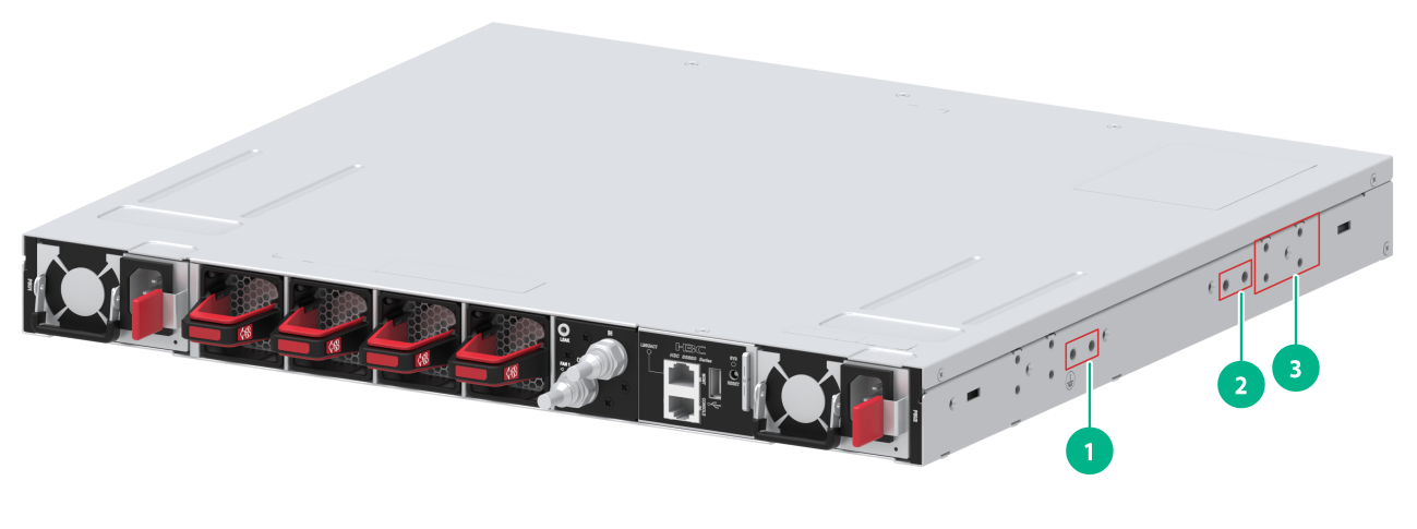
Mounting brackets, chassis rails, and grounding cable installation positions
The LS-6850-56HF-CP switch provides two grounding points: primary grounding point (with a grounding sign) and auxiliary grounding point, as shown in Figure2-10.
Select installation positions for the mounting brackets, chassis rails, and grounding cable as required.
|
(1) Primary grounding point |
(2) Auxiliary grounding point |
|
(3) Port-side installation position for the mounting bracket |
|
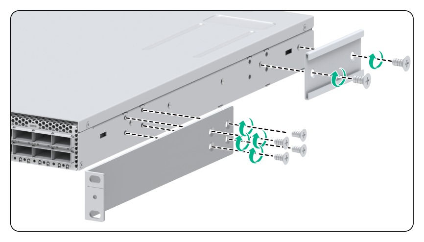
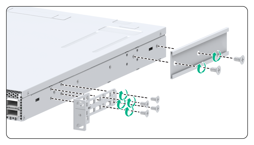
Attaching the mounting brackets and chassis rails to the chassis
1. Place the wide flange of the mounting bracket against the chassis side panel. Align the mounting bracket installation holes with the appropriate screw holes in the chassis. Use the provided M4 screws to attach the mounting bracket to the chassis.
¡ To install the mounting brackets at the port-side mounting position, see Figure2-11, Figure2-12, Figure2-13, and Figure2-14.
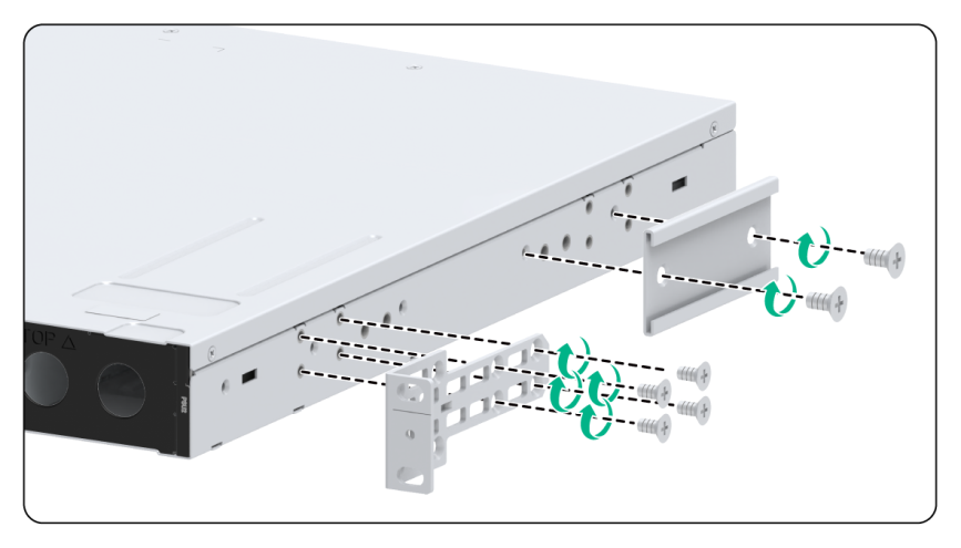
¡ To install the mounting brackets at the power module-side mounting position, see Figure2-15 and Figure2-16.
2. Place the chassis rail against the chassis side panel. Align the chassis rail installation holes with the screw holes. Use the provided M4 screws to attach the chassis rail to the chassis. See Figure2-11 to Figure2-16.
As a best practice, use a torque of 12 kgf-cm (1.18 Nm) to fasten the M4 screws.
Figure2-11 Attaching the extended mounting brackets and chassis rails to the LS-6850-56HF-CP switch (port-side mounting position for the mounting brackets, short slide rails)


|
|
NOTE: · Secure the mounting brackets and chassis rails to both sides of the chassis in the same way. · You can use super-short slide rails and chassis rails to rack-mount the switch. Based on the rack depth, install the chassis rails with the chassis rails not reaching out of the chassis, as shown in Figure2-13 or with the chassis rails reaching out of the chassis, as shown in Figure2-14 and Figure2-16. · To install the mounting brackets at the port-side mounting position, use the four screw holes nearest to the port side. To install the mounting brackets at the power module-side mounting position, use the four screw holes nearest to the power module side. |
Connecting the grounding cable to the chassis
|
|
IMPORTANT: · If the grounding cable length or terminal type cannot meet your requirement, make an applicable grounding cable or contact H3C Support. · If you use a grounding point on the side panel to ground the switch, connect the grounding cable to the grounding point before installing the switch in the liquid-cooled rack. |
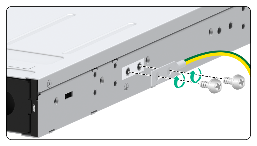
The primary grounding point and auxiliary grounding point are on the left side panel. Both grounding points support a grounding cable that has a single-hole lug or dual-hole lug. Use M5 grounding screws to attach the grounding cable to the switch. If you install the mounting brackets at the port side, connect the grounding cable to the grounding point at the port side.
To connect the grounding cable:
1. Choose a grounding point as required.
2. Unpack the grounding cable and grounding screws.
3. Use the grounding screws to attach the grounding lug of the grounding cable to the grounding holes at the grounding point. Use a screwdriver to fasten the screws. See Figure2-17 and Figure2-18.
As a best practice, use a torque of 30 kgf-cm (2.94 Nm) to fasten the grounding screws.
Figure2-17 Attaching a grounding cable that has a single-hole lug to the grounding point

Figure2-18 Attaching a grounding cable that has a dual-hole lug to the grounding point
Attaching the slide rails to the rack
1. Identify the planned slide rail installation position in the rack.
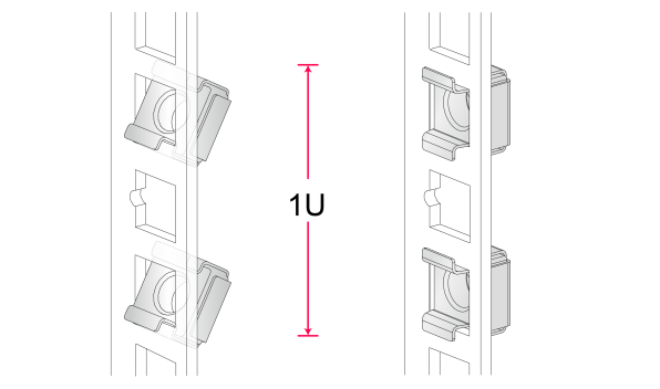
Plan a 1U rack space for installation of 1U slide rails. Figure2-19 shows a standard 1U rack space.
In a standard 1U rack space, there are three installation holes, one in the middle for auxiliary installation and one at either end for standard installation. The spacing between two adjacent standard installation holes is slightly smaller than the distance between a standard installation hole and the middle, auxiliary installation hole.
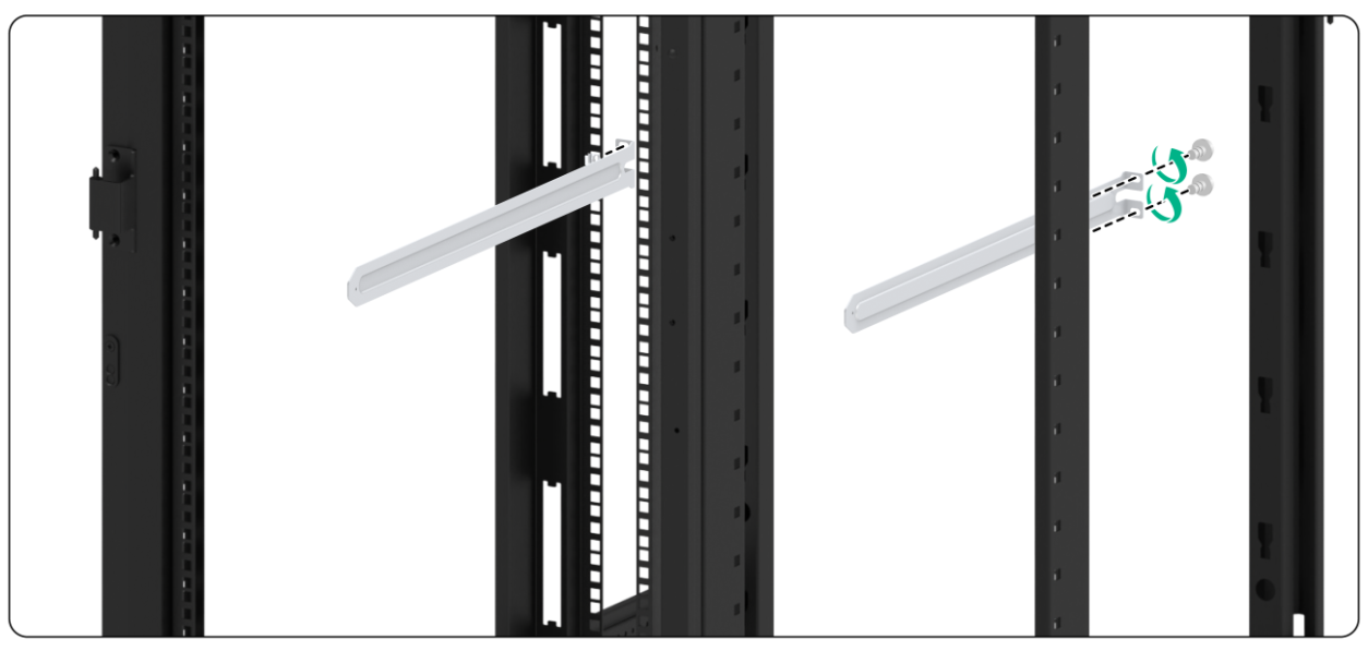
2. Install cage nuts (user-supplied) in the mounting holes in the rack posts.
3. Align the screw holes in one slide rail with the cage nuts in a rear rack post. Use user-supplied M6 screws to attach the slide rail to the post. See Figure2-20.
As a best practice, use a torque of 30 kgf-cm (2.94 Nm) to fasten the M6 screws.
4. Repeat the preceding steps to attach the other slide rail to the other rear rack post.
Keep the two slide rails at the same height so the slide rails can attach into the chassis rails.
Figure2-20 Installing the 1U slide rails
Mounting the switch in the rack
1. Wear an ESD wrist strap and make sure it makes good skin contact and is reliably grounded.
2. Verify that the mounting brackets and chassis rails have been securely attached to the switch chassis. For more information, see "Attaching the mounting brackets and chassis rails to the chassis."
3. Verify that the slide rails have been correctly attached to the rear rack posts. For more information, see "Attaching the slide rails to the rack."
4. Attach cage nuts (user-supplied) to the front rack posts and make sure they are at the same level as the slide rails.
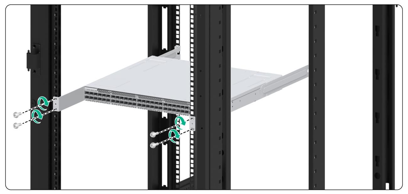
5. One person performs the following operations:
a. Supporting the bottom of the switch, aligns the chassis rails with the slide rails on the rack posts.
b. Pushes the switch slowly to slide the chassis rails along the slide rails until the mounting brackets are flush with the rack posts.
|
|
IMPORTANT: If you use long slide rails to rack-mount the switch, make sure the front ends of the long slide rails reach out of the chassis rails for a minimum of 20 mm (0.79 in). If you use super-short slide rails to rack-mount the switch, make sure the front ends of the super-short slide rails reach inside the chassis rails for a minimum of 110 mm (4.33 in) after installation. |
6. The other person uses user-supplied M6 screws and cage nuts (with surfaces treated for corrosion protection) to attach the mounting brackets to the rack and verifies that the brackets are level and secure.
As a best practice, use a torque of 30 kgf-cm (2.94 Nm) to fasten the M6 screws.
Figure2-21 Mounting the S6850-56HF-CP switch in the liquid-cooled rack
Grounding the switch
|
|
CAUTION: · Correctly connecting the grounding cable is crucial to lightning protection and EMI protection. · Connect the grounding cable to the grounding system in the equipment room. Do not connect it to a fire main or lightning rod. · To guarantee the grounding effect and avoid switch damage, use the grounding cable provided with the switch to connect the switch to a grounding strip in the equipment room. |
|
|
NOTE: The grounding terminals in this section are for illustration only. |
The power input end of the switch has a noise filter, whose central ground is directly connected to the chassis to form the chassis ground (commonly known as PGND). You must securely connect this chassis ground to the earth so the faradism and leakage electricity can be safely released to the earth to minimize EMI susceptibility of the switch.
To connect the grounding cable:
1. Attach the two-hole grounding lug of the grounding cable to a grounding point on the chassis. For more information, see "Mounting the switch in the rack_Ref461022702."
2. Remove the hex nut of a grounding post on the grounding strip.
3. Attach the ring terminal of the grounding cable to the grounding post on the grounding strip, and secure the ring terminal to the grounding post with the hex nut.
Figure2-22 Connecting the grounding cable to a grounding strip

|
(1) Hex nut |
(2) Ring terminal |
|
(3) Grounding post |
(4) Grounding strip |
Installing/removing fan trays
|
|
CAUTION: The switch has four fan tray slots. To ensure good ventilation of the switch, follow these guidelines to install and remove fan trays: · The switch comes with the fan tray slots empty. For adequate heat dissipation of the switch, fully configure the switch with fan trays of the same model. If the number of installed fan trays is less than the minimum required number, the device will output an error message and does not power up. · Make sure all slots have a module or filler panel installed when the switch is operating. · If multiple fan trays fail on an operating switch, do not remove the fan trays at the same time. Replace the fan trays one after another and finish replacing a fan tray within 3 minutes. |
|
|
CAUTION: · Do not touch any bare cables or terminals on the fan tray. · Do not place the fan tray in a wet area, and prevent liquid from entering into the fan tray. · When an internal circuit or component of the fan tray fails, contact H3C Support. Do not remove any component from the fan tray yourself. |
The installation and removal procedures are the same for fan trays of different models. The following installation and removal procedures use the FAN-40B-1-C fan tray as examples.
Installing a fan tray
|
|
CAUTION: To prevent damage to the fan tray or the connectors on the backplane, insert the fan tray gently. If you encounter a hard resistance while inserting the fan tray, pull out the fan tray and insert it again. |
|
|
IMPORTANT: Before powering on the switch, make sure the fan tray airflow direction and the preferred airflow direction of the switch are the same. If they are not the same, the system generates traps and logs. You can use the fan prefer-direction command to configure the preferred airflow direction for the switch. By default, the preferred airflow direction of the switch is from the port side to the power module side. For more information about the fan prefer-direction command, see H3C S6805 & S6825 & S6850 & S9850 Switch Series Fundamentals Command Reference. |
Select fan trays for the switch as needed. For the available fan trays and their specifications, see H3C S6850-56HF-CP Cold Plate-Based Liquid-Cooled Switch Hardware Information and Specifications.
To install a fan tray:
1. Wear an ESD wrist strap and make sure it makes good skin contact and is reliably grounded.
2. Unpack the fan tray and verify that the fan tray model is correct.
3. Orient the fan tray with the connector facing downwards. Grasping the handle of the fan tray with one hand and supporting the fan tray bottom with the other, slide the fan tray along the guide rails into the slot until the fan tray is fully seated in the slot and has a firm contact with the backplane. See Figure2-23.
Figure2-23 Installing a FAN-40B-1-C fan tray in the LS-6850-56HF-CP switch
Removing a fan tray
|
|
WARNING! · Ensure electricity safety and never touch the rotating fans when you hot swap a fan tray. · To prevent a fan from causing loud noise, do not touch the fan blades and rotation axis, even if the fan is not rotating. |
To remove a fan tray:
1. Wear an ESD wrist strap and make sure it makes good skin contact and is reliably grounded.
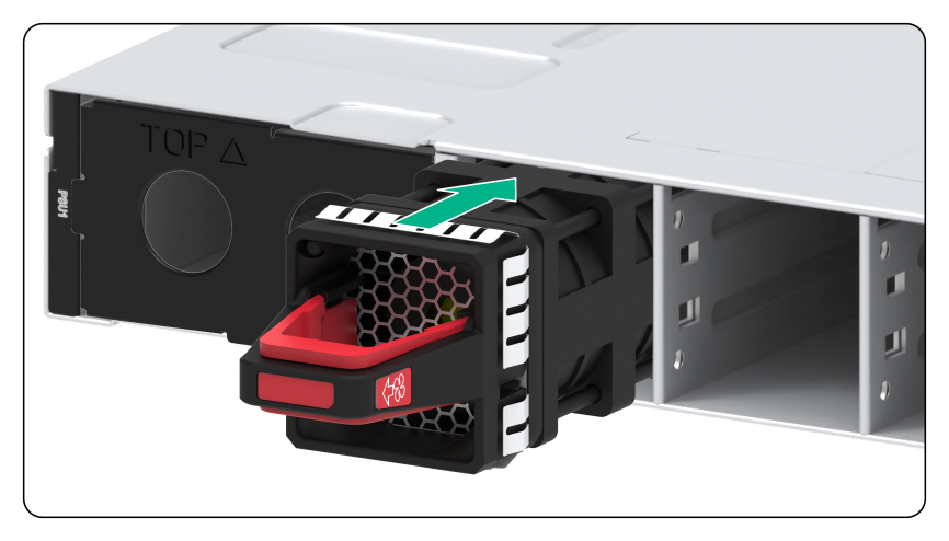
2. Pressing the red part of the handle, pull the fan tray slowly out of the slot along the guide rails. See Figure2-24.
3. Put the removed fan tray in an antistatic bag.
Figure2-24 Removing a FAN-40B-1-C fan tray

Installing/removing power modules
|
|
WARNING! · To avoid bodily injury and device damage, strictly follow the procedures in Figure2-25 and Figure2-26 to install and remove a power module. · Provide a separate circuit breaker for each power module. |
The S6850-56HF-CP switch comes with one power module slot empty and one installed with a filler panel. You can install power modules for the switch as required. For the available power modules and their specifications, see H3C S6850-56HF-CP Cold Plate-Based Liquid-Cooled Switch Hardware Information and Specifications.
Figure2-25 Installation procedure
![]()
![]()
Safety guidelines
To prevent device damage and even bodily injury, follow these restrictions and guidelines when you install or remove a power module:
· Always wear an ESD wrist strap and make sure the strap makes good skin contact.
· Before installing a power module, make sure the voltage of the power source is as required by the power module, and the output voltage of the power module is as required by the device.
· Do not touch any bare cables or terminals on the power module.
· Do not place the power module in a wet area, and prevent liquid from entering the power module.
· To avoid power module damage, do not open the power module. When an internal circuit or component of the power module fails, contact H3C Support.
Installing a power module
|
|
CAUTION: · Follow the forward inertia of the power module when inserting it into the chassis, and make sure the power module has firm contact with the connectors on the backplane. · To prevent damage to the connectors inside the switch chassis, insert the power module gently. If you encounter a hard resistance while inserting the power module, pull out the power module and insert it again. |
The switch supports shipping with fan trays and power modules installed. If your switch comes with power modules preinstalled, skip this section.
To install a power module:
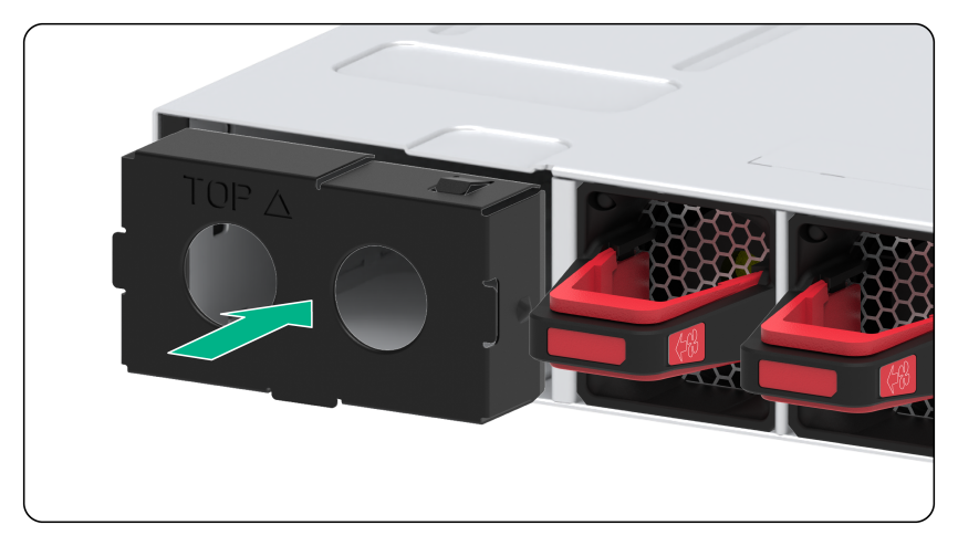
1. Remove the filler panel, if any, from the target power module slot, as shown in Figure2-27.
Figure2-27 Removing a filler panel

2. Unpack the power module and verify that the power module model is correct.
3. Correctly orient the power module with the words on the power module upward. Grasping the handle of the power module with one hand and supporting its bottom with the other, slide the power module slowly along the guide rails into the slot.
3.The slot is foolproof. If you cannot insert the power module into the slot, re-orient the power module rather than use excessive force to push it in.
Figure2-28 Installing a power module

Removing a power module
|
|
CAUTION: When the switch has power modules in 1+1 redundancy mode, removing one power module does not affect the operation of the switch. When the switch has only one power module installed, removing the power module powers off the switch. |
To remove a power module:
1. Remove the power cord from the power module.
2. As shown in Figure2-29, hold the handle on the power module with one hand, pivot the latch on the power module to the left with your thumb, and pull the power module part way out of the slot. Supporting the power module bottom with the other hand, slowly pull the power module out of the slot.
Figure2-29 Removing a power module

|
(1) Pivot the latch to the left with your thumb |
(2) Pull the power module out |
3. Put the removed power module in an antistatic bag for future use.
4. If you are not to install a new power module, install a filler panel in the slot to ensure good ventilation in the switch, as shown in Figure2-30.
Figure2-30 Installing a filler panel
Connecting/disconnecting liquid-cooled pipes
Connecting liquid-cooled pipes
|
|
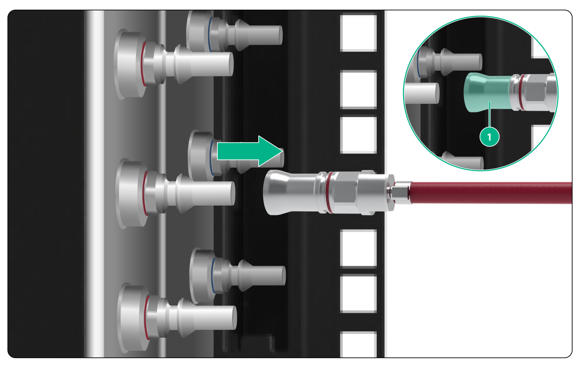
IMPORTANT: · When you connect liquid-cooled pipes, first connect quick connectors on the pipes to the manifold. Before you connect quick connectors, remove the covers from the quick connectors on the switch and the water inlet and outlet pipes. Keep the removed covers secure for future use. Check the connectors for object intrusions and leakage. · Arrange the routing path of the water inlet and outlet pipes promptly to avoid squeezing or excessively bending the pipes. Ensure a minimum bending radius of greater than 100 mm (3.94 in). · After you disconnect the quick connectors, install the covers for them immediately. · Correctly connect the water inlet and outlet pipes based on the red and blue marks on the liquid-cooled rack. Connect the red water outlet pipe and blue water inlet pipe to the OUT and IN male connectors on the switch, respectively. |
To connect liquid-cooled pipes:
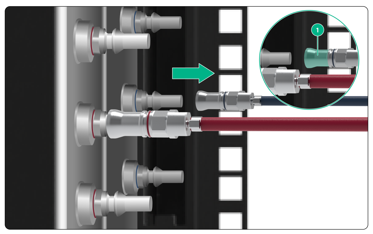
1. As shown in Figure2-31, orient a female quick connector on the red water outlet pipe with a male quick connector on the manifold (with a red mark). Hold the shell of the female quick connector (as shown by callout 1) and push it into the male quick connector until it clicks into place. For more information about the manifold, see H3C Cold Plate-Based Liquid-Cooling System User Guide.
Figure2-31 Connecting a quick connector on the red water outlet pipe to the manifold

Figure2-32 Connected a quick connector on the red water outlet pipe to the manifold

2. As shown in Figure2-33, use the same method to connect a quick connector on the blue water inlet pipe to the manifold. Orient the female quick connector on the pipe with a male quick connector on the manifold (with a blue mark).
Figure2-33 Connecting a quick connector on the blue water inlet pipe to the manifold

3. As shown in Figure2-34, orient the other female quick connector on the blue water inlet pipe with the IN male connector on the switch cold plate. Hold the shell of the female quick connector (as shown by callout 1) and push it into the IN male connector until it clicks into place.
Figure2-34 Connecting a quick connector on the blue water inlet pipe to the switch cold plate

Figure2-35 Connected a quick connector on the blue water inlet pipe to the switch cold plate
4. As shown in Figure2-36, use the same method to connect the other quick connector on the red water outlet pipe to the switch cold plate. Orient the female quick connector on the pipe with the OUT male connector on the switch cold plate.
Figure2-36 Connected a quick connector on the red water outlet pipe to the switch cold plate

Disconnecting liquid-cooled pipes
1. Power off the switch and disconnect all power cords.
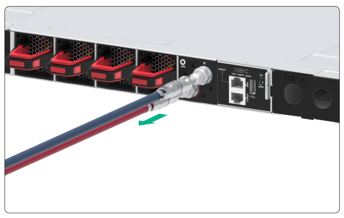
2. As shown in Figure2-37, hold and pull the shell of the female quick connector (as shown by callout 1) on the blue water inlet pipe to release the female quick connector. Then, disconnect the female quick connector from the manifold.
Figure2-37 Disconnecting the female quick connector on the blue water inlet pipe from the manifold
3. Use the same method to disconnect the female quick connector on the red water outlet pipe from the manifold.
Figure2-38 Disconnecting the female quick connector on the red water outlet pipe from the manifold
4. Use the same method to disconnect the female quick connectors on the water inlet and outlet pipes from the switch.
Figure2-39 Disconnecting the female quick connector on the blue water inlet pipe from the switch
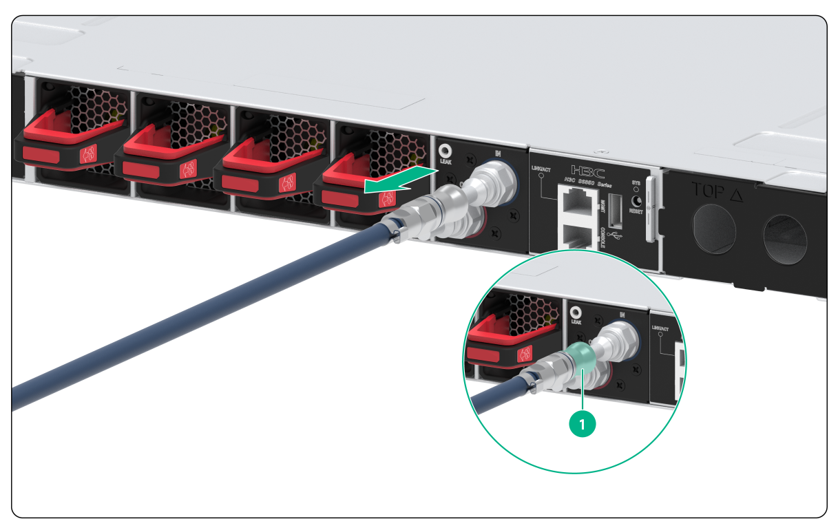
Figure2-40 Disconnecting the female quick connector on the red water outlet pipe from the switch
Connecting the power cords
|
|
WARNING! Provide a circuit breaker for each power input. When you connect a power cord, make sure the circuit breaker is switched off. |
1. Insert the female connector of the AC power cord supplied with the power module into the power receptacle on the power module.
2. Use a Velcro cable strap to secure the power cord to the handle of the power module, as shown in Figure2-41.
3. Connect the other end of the power cord to an external AC power source.
Figure2-41 Connecting an AC power cord

Verifying the installation
After you complete the installation, verify the following information:
· There is enough space around the switch for heat dissipation.
· The rack is stable.
· The grounding cable is connected correctly.
· The power source is as required by the switch.
· The power cord is correctly connected.
· All the interface cables are cabled indoors. The switch does not support outdoor cable routing.
3 Accessing the switch for the first time
Connecting the switch to a configuration terminal
You can access the switch through the serial console port.
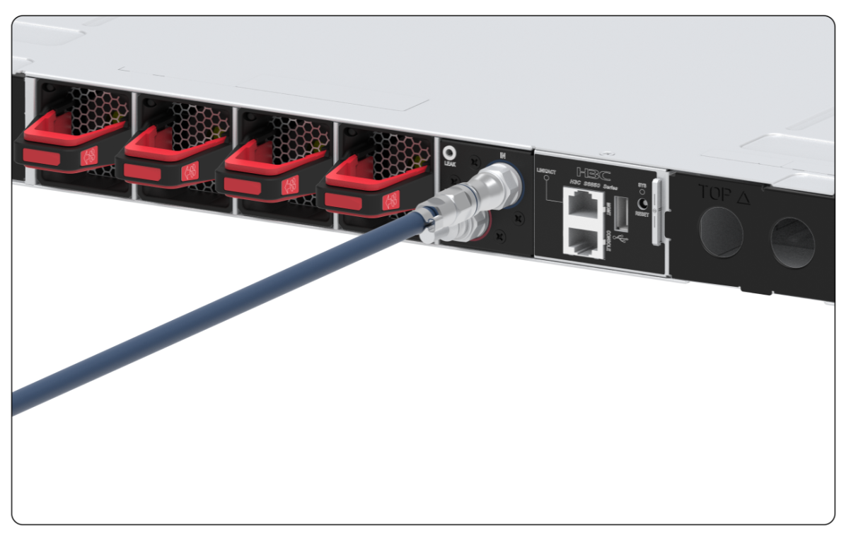
In Figure3-1, the switch is connected to a configuration terminal (PC as an example) from the serial console port.
Figure3-1 Connecting the serial console port to a terminal

As shown in Table3-1, two types of console cables can be used for connecting the switch to a configuration terminal. The switch is not provided with a serial console cable.
Table3-1 Connection methods and console cables
|
Connection method |
Console cable type |
Configuration terminal-side connector |
Switch-side connector |
|
Using the serial console port for connection |
DB9-to-RJ45 console cable |
DB-9 female connector |
RJ-45 connector |
|
USB-to-RJ45 console cable |
USB connector |
RJ-45 connector |
The signal pinout for the RJ-45 connector of a serial console cable varies by vendor. To avoid abnormal configuration terminal display, use a serial console cable provided by H3C. For more information, see Table3-2. To prepare a serial console cable yourself, make sure the signal pinout for the RJ-45 connector is the same as that shown in Table3-3.
|
Console cable type |
Console cable view |
Product code for the recommended H3C console cable |
|
DB9-to-RJ45 console cable |
|
04042967 |
|
USB-to-RJ45 console cable |
|
0404A1EE |


Connecting the console cable
Connecting a DB9-to-RJ45 console cable
A serial console cable is an 8-core cable, with a crimped RJ-45 connector at one end for connecting to the serial console port of the switch, and a DB-9 female connector at the other end for connecting to the serial port on the console terminal.
Figure3-2 Serial console cable

Table3-3 Console port signaling and pinout
|
RJ-45 |
Signal |
DB-9 |
Signal |
|
1 |
RTS |
8 |
CTS |
|
2 |
DTR |
6 |
DSR |
|
3 |
TXD |
2 |
RXD |
|
4 |
SG |
5 |
SG |
|
5 |
SG |
5 |
SG |
|
6 |
RXD |
3 |
TXD |
|
7 |
DSR |
4 |
DTR |
|
8 |
CTS |
7 |
RTS |
To connect a configuration terminal (for example, a PC) to the switch through a DB9-to-RJ45 console cable:
1. Plug the DB-9 female connector of the DB9-to-RJ45 console cable to the serial port on the PC.
2. Connect the RJ-45 connector to the serial console port on the switch.
|
|
NOTE: · Identify the mark on the console port and make sure you are connecting to the correct port. · The serial ports on PCs do not support hot swapping. To connect a PC to an operating switch, first connect the PC end. To disconnect a PC from an operating switch, first disconnect the switch end. |
Connecting a USB-to-RJ45 console cable
|
|
IMPORTANT: · To use a USB-to-RJ45 console cable to connect the switch to a configuration terminal, first download and install the USB-to-RJ45 console driver on the configuration terminal and then connect the USB-to-RJ45 console cable to the configuration terminal. · If you have connected a USB-to-RJ45 console cable to the configuration terminal before driver installation, you must remove and reconnect the USB-to-RJ45 console cable to the configuration terminal. |
For information about the signal pinout for the RJ-45 connector of a USB-to-RJ45 console cable, see Table3-3.
The following procedure describes how to install the driver on the Windows system. To install the driver on other operating systems, see the installation guide in the driver compression package named by the corresponding operating system.
To connect the switch to the configuration terminal through a USB-to-RJ45 console cable:
1. Click the following link, or copy it to the address bar on your browser and download the USB-to-RJ45 console driver.
http://www.h3c.com/en/home/USB_to_RJ45_Console/
2. View the TXT file Read me in the Windows folder to check whether the Windows system of the configuration terminal supports the driver.
3. If the Windows system supports the driver, install PL23XX-M_LogoDriver_Setup_v200_20190815.exe.
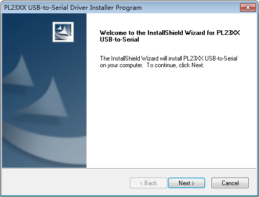
4. Click Next on the welcome page of the driver installation wizard.
Figure3-3 Driver installation wizard
5. Click Finish after the drive installation is completed.
Figure3-4 Finishing the driver installation

6. Connect the standard USB connector of the cable to the USB port of the configuration terminal.
7. Connect the RJ-45 connector of the cable to the console port of the switch.
Setting terminal parameters
To configure and manage the switch through the console port, you must run a terminal emulator program, TeraTermPro or PuTTY, on your configuration terminal. You can use the emulator program to connect a network device, a Telnet site, or an SSH site. For more information about the terminal emulator programs, see the user guides for these programs
The following are the required terminal settings:
· Bits per second—9600.
· Data bits—8.
· Stop bits—1.
· Parity—None.
· Flow control—None.
Powering on the switch
1. Before powering on the switch, verify that the following conditions are met:
¡ All the fan tray slots have a fan tray installed.
¡ The liquid-cooled pipes and cables are connected correctly.
¡ The power cords are connected correctly.
¡ The input power voltage is as required by the switch.
¡ The console cable is connected correctly.
¡ The configuration terminal (a PC, for example) has started, and its serial port settings are consistent with the console port settings on the switch.
2. Power on the switch.
During the startup process, you can access BootWare menus to perform tasks such as software upgrade and file management. The BootWare interface and menu options vary by software version. For more information about BootWare menu options, see the software-matching release notes for the device.
3. After the startup completes, you can access the CLI to configure the switch.
For more information about the configuration commands and CLI, see H3C S6805 & S6825 & S6850 & S9850 Switch Series Configuration Guides and H3C S6805 & S6825 & S6850 & S9850 Switch Series Command References.
4 Setting up an IRF fabric
You can use H3C IRF technology to connect and virtualize multiple S6850-56HF-CP switches into a large virtual switch called an "IRF fabric" for flattened network topology, and high availability, scalability, and manageability.
IRF fabric setup flowchart
Figure4-1 IRF fabric setup flowchart

To set up an IRF fabric:
|
Step |
Description |
|
1. Plan IRF fabric setup. |
Plan the installation site and IRF fabric setup parameters: · Planning IRF fabric size and the installation site · Identifying the master switch and planning IRF member IDs · Planning IRF topology and connections |
|
2. Install IRF member switches. |
|
|
3. Connect the grounding cable and power cords. |
See "Grounding the switch" and "Connecting the power cords." |
|
4. Power on the switches. |
N/A |
|
5. Configure basic IRF settings. |
See IRF configuration in H3C S6805 & S6825 & S6850 & S9850 Switch Series Virtual Technologies Configuration Guide. |
|
6. Connect the physical IRF ports. |
Connect the physical IRF ports on switches. Use QSFP28/QSFP+ transceiver modules and fibers for connections over long distances. Use QSFP28/QSFP+ cables for connections over short distances. All switches except the master switch automatically reboot, and the IRF fabric is established. |
Planning IRF fabric setup
This section describes issues that an IRF fabric setup plan must cover.
Planning IRF fabric size and the installation site
Determine the number of required IRF member switches, depending on the user density and upstream bandwidth requirements. The switching capacity of an IRF fabric equals the total switching capacities of all member switches.
An S6850-56HF-CP switch can set up an IRF fabric only with S6850-56HF-CP switches.
Plan the installation site depending on your network solution as follows:
· Place all IRF member switches in one rack for centralized high-density access.
· Distribute the IRF member switches in different racks to implement the top-of-rack (ToR) access solution for a data center.
As your business grows, you can add member switches into the IRF fabric to increase the switching capacity without any topology change or replacement.
Identifying the master switch and planning IRF member IDs
Determine which switch you want to use as the master for managing all member switches in the IRF fabric. An IRF fabric has only one master switch. You configure and manage all member switches in the IRF fabric at the command line interface of the master switch.
|
|
NOTE: IRF member switches will automatically elect a master. You can affect the election result by assigning a high member priority to the intended master switch. For more information about master election, see IRF configuration in H3C S6805 & S6825 & S6850 & S9850 Switch Series Virtual Technologies Configuration Guide. |
Prepare an IRF member ID assignment scheme. An IRF fabric uses member IDs to uniquely identify and manage its members, and you must assign each IRF member switch a unique member ID.
Planning IRF topology and connections
You can create an IRF fabric in daisy chain topology, or more reliably, ring topology. In ring topology, the failure of one IRF link does not cause the IRF fabric to split as in daisy chain topology. Rather, the IRF fabric changes to a daisy chain topology without interrupting network services.
You connect the IRF member switches through IRF ports, the logical interfaces for the connections between IRF member switches. Each IRF member switch has two IRF ports: IRF-port 1 and IRF-port 2. To use an IRF port, you must bind a minimum of one physical port to it.
When connecting two neighboring IRF member switches, you must connect the physical ports of IRF-port 1 on one switch to the physical ports of IRF-port 2 on the other switch.
The IRF port connections in the two figures are for illustration only, and more connection methods are available.
Figure4-2 IRF fabric in daisy chain topology
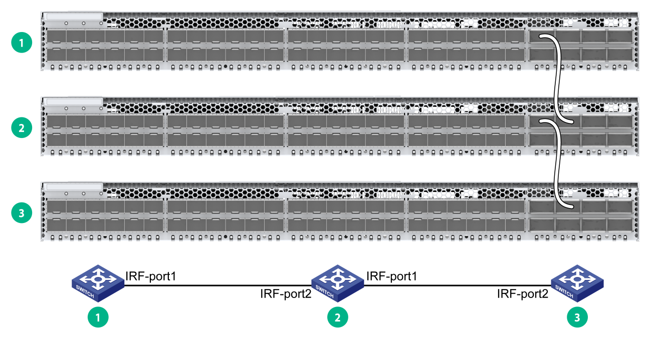
Figure4-3 IRF fabric in ring topology

You can set up IRF links between S6850-56HF-CP switches as follows:
· Use a QSFP28 module and fiber or a QSFP28 cable to connect QSFP28 ports for a 100-GE IRF physical connection.
· Use a QSFP+ module and fiber or a QSFP+ cable to connect QSFP28 ports for a 40-GE IRF physical connection.
You can bind several ports to an IRF port for increased bandwidth and availability.
When you use a QSFP+ DAC cable to connect a pair of peer IRF physical interfaces, the peer interfaces must both be fixed ports or both be ports on expansion modules that are the same model.
Identifying physical IRF ports on the member switches
Identify the physical ports for IRF connections on the member switches according to your topology and connection scheme.
All the QSFP28 ports on the switch can be used for IRF connections.
Planning the cabling scheme
You can use QSFP28/QSFP+ cables, or QSFP28/QSFP+ transceiver modules and fibers to connect the S6850-56HF-CP switches for IRF connections.
If the switches are all in one equipment room, choose QSFP28/QSFP+ cables for IRF connections. If the switches are far away from one another, choose QSFP28/QSFP+ transceiver modules and fibers for IRF connections.
For more information about available cables, see H3C S6850-56HF-CP Cold Plate-Based Liquid-Cooled Switch Hardware Information and Specifications.
The following subsections describe several IRF connection schemes by using the QSFP28 cables and QSFP28 transceiver modules and fibers. As a best practice, use the ring topology for IRF connections.
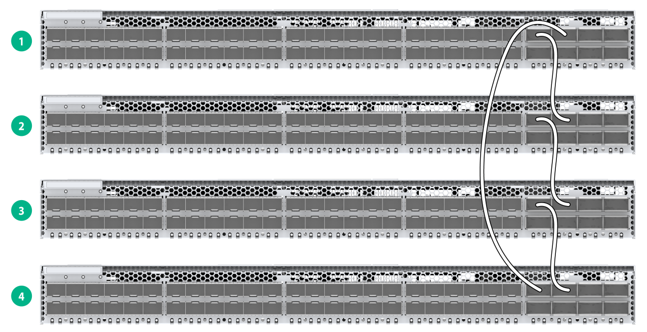
Connecting the IRF member switches in one rack
Figure4-4 shows an example for connecting four IRF member switches in a rack. The switches in the ring topology (see Figure4-5) are in the same order as connected in the rack.
Figure4-4 Connecting the switches in one rack
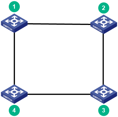
Connecting the IRF member switches in a ToR solution
You can install IRF member switches in different racks side by side to deploy a top of rack (ToR) solution.
Figure4-6 shows an example for connecting four top of rack IRF member switches. The topology is the same as Figure4-5.

Configuring basic IRF settings
After you install the IRF member switches, power on the switches, and log in to each IRF member switch (see H3C S6805 & S6825 & S6850 & S9850 Switch Series Fundamentals Configuration Guide) to configure their member IDs, member priorities, and IRF port bindings.
Follow these guidelines when you configure the switches:
· Assign the master switch higher member priority than any other switch.
· Bind physical ports to IRF port 1 on one switch and to IRF port 2 on the other switch. You perform IRF port binding before or after connecting IRF physical ports depending on the software release.
· Execute the display irf configuration command to verify the basic IRF settings.
For more information about configuring basic IRF settings, see H3C S6805 & S6825 & S6850 & S9850 Switch Series Virtual Technologies Configuration Guide.
Connecting the physical IRF ports
|
|
CAUTION: Wear an ESD wrist strap when you install transceiver modules, fibers, and cables. For more information, see the installation guide. |
Use transceiver modules and fibers or cables to connect the IRF member switches as planned.
Accessing the IRF fabric to verify the configuration
To verify the basic functionality of the IRF fabric after you finish configuring basic IRF settings and connecting IRF ports:
1. Log in to the IRF fabric through the console port of any member switch.
2. Create a Layer 3 interface, assign it an IP address, and make sure the IRF fabric and the remote network management station can reach each other.
3. Use Telnet or SNMP to access the IRF fabric from the network management station. (See H3C S6805 & S6825 & S6850 & S9850 Switch Series Fundamentals Configuration Guide.)
4. Verify that you can manage all member switches as if they were one node.
5. Display the running status of the IRF fabric by using the commands in Table4-1.
Table4-1 Displaying and maintaining IRF configuration and running status
|
Task |
Command |
|
Display information about the IRF fabric. |
display irf |
|
Display all members' IRF configurations. |
display irf configuration |
|
Display IRF fabric topology information. |
display irf topology |
|
|
NOTE: To avoid IP address collision and network problems, configure at least one multi-active detection (MAD) mechanism to detect the presence of multiple identical IRF fabrics and handle collisions. For more information about MAD detection, see H3C S6805 & S6825 & S6850 & S9850 Switch Series Virtual Technologies Configuration Guide. |
5 Setting up an M-LAG system
Multichassis Link Aggregation (M-LAG) virtualizes two physical devices into one system through multichassis link aggregation to provide device-class high availability and load sharing.
Compared to IRF, M-LAG offers higher network reliability and shorter service interruption during upgrade.
You cannot configure IRF and M-LAG on the same network.
|
|
IMPORTANT: The device supports both the M-LAG set and DRNI set of command keywords in the CLI by default. The two sets of commands are consistent in the service configuration methods, functions, and output, with only differences in the command keywords. For the differences in the command keywords, see M-LAG configuration in Layer 2—LAN Switching Configuration Guide of H3C S6805 & S6825 & S6850 & S9850 Switch Series Configuration Guides-Release 671x. |
M-LAG system setup flowchart
Figure5-1 M-LAG system setup flowchart

To set up an M-LAG system:
|
Step |
Description |
|
1. Plan for setting up the M-LAG system. |
Plan for setting up the M-LAG system based on the network and device conditions: · Determine the installation locations of the switches. · Reserve physical ports for M-LAG connections. · Plan the cable connection scheme. For more information, see "Planning for setting up an M-LAG system." |
|
2. Install M-LAG member switches. |
|
|
3. Connect the grounding cable and power cords for the member switches. |
See "Grounding the switch" and "Connecting the power cords." |
|
4. Power on the switches. |
N/A |
|
5. Configure the M-LAG system settings. |
For detailed information about M-LAG, see M-LAG configuration in H3C S6805 & S6825 & S6850 & S9850 Switch Series Layer 2—LAN Switching Configuration Guide. |
|
6. Connect the member switches. |
Select cables or transceiver modules and optical fibers matching the rate of the physical ports of the peer link and keepalive link for connection. |
Planning for setting up an M-LAG system
Determining device installation locations
An M-LAG system can be set up with only two devices. Reserve sufficient space in the rack for installation of the devices.
You can place the two switches in one rack. Alternatively, you can install the switches in two racks if you're seeking a top-of-rack access solution in the data center.
Reserving physical ports for M-LAG connection
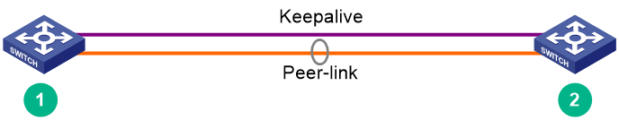
To set up an M-LAG system, you must establish a peer link and a keepalive link between the two devices.
The M-LAG member devices exchange protocol packets and transmit data traffic over the peer link. An M-LAG system has only one peer link. You can create a peer-link interface on each M-LAG member device, and the link between the two peer-link interfaces is the peer link.
The M-LAG member devices exchange keepalive packets over the keepalive link to detect multi-active collisions when the peer link is down.
Peer link
In addition to protocol packets, the peer link also transmits data packets between the M-LAG member devices when an uplink fails. When you set up the peer link, follow these restrictions and guidelines:
· Configure the peer-link aggregation group as follows:
¡ If an M-LAG member device is a fixed-port device with interface expansion modules, assign ports from multiple interface expansion modules to the aggregation group for the peer-link interface. Make sure at least one member port resides on a different slot than the uplink interfaces.
¡ If an M-LAG member device is a fixed-port device, assign at least two physical interfaces to the aggregation group for the peer-link interface.
· The member ports in the aggregation group for the peer-link interface must have the same speed.
· If an M-LAG system is attached to a large number of servers by using non-M-LAG interfaces, take the size of the traffic sent among those servers into account when you determine the bandwidth of the peer link.
Keepalive link
As a best practice, establish a dedicated direct link between two M-LAG member devices as a keepalive link. Do not use the keepalive link for any other purposes. Make sure the M-LAG member devices have Layer 2 and Layer 3 connectivity to each other over the keepalive link.
You can use management Ethernet interfaces, Layer 3 Ethernet interfaces, Layer 3 aggregate interfaces, or interfaces with a VPN instance bound to set up the keepalive link.
As a best practice, do not use VLAN interfaces for keepalive link setup. If you have to use VLAN interfaces, remove the peer-link interfaces from the related VLANs to avoid loops.
On a device with interface expansion modules, do not use the same module to provide interfaces for setting up the keepalive link and peer link.
Planning the cable connection scheme
Select cables or transceiver modules and optical fibers matching the rate of physical ports of the peer link and the keepalive link for connection.
Cables are short but with high performance and stability, suitable for short-distance connections in the equipment room. Transceiver modules and optical fibers can be combined flexibly and is suitable for longer distance connections.
For information about the transceiver modules and cables supported by the switch, see H3C S6850-56HF-CP Cold Plate-Based Liquid-Cooled Switch Hardware Information and Specifications.
This following section describes several cable connection schemes that use 100G physical ports for the peer link connection and 25G physical ports for the keepalive link connection, with matching cables or transceiver module and optical fibers.
|
|
NOTE: The physical port locations in the following figures are for illustration only. |
Connecting the member switches in one rack
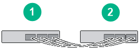
If two M-LAG member devices are installed in the same rack, use the following connection method to connect them as a best practice.
Figure5-2 Connecting two M-LAG member devices are installed in the same rack
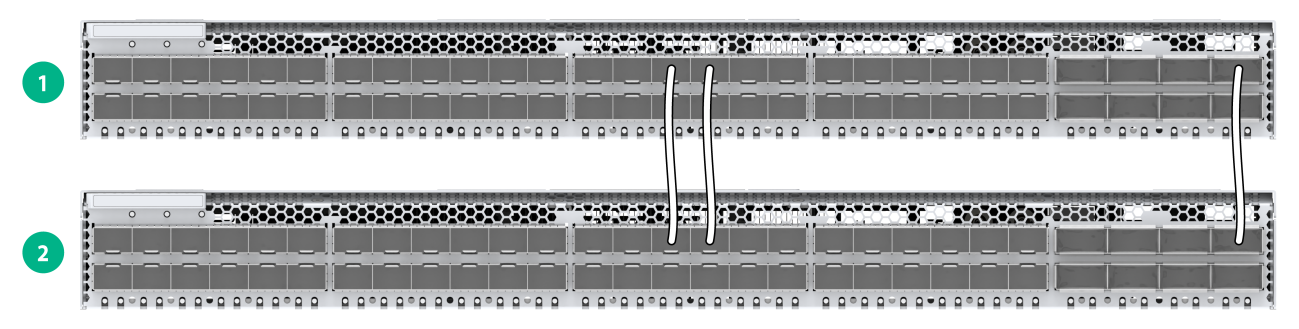
Figure5-3 Connection topology of two M-LAG member devices in the same rack
Top of rack connection scheme
You can install M-LAG member switches in two different racks side by side to deploy a top of rack (ToR) solution as shown in Figure5-4. Use transceiver modules and optical fibers for connection if a large distance exists between the member switches.
Figure5-4 Top of rack connection scheme
Configuring the M-LAG system settings
After you install the M-LAG member switches, start and log in to each member switch to configure basic M-LAG system settings, including:
· M-LAG system MAC address.
· M-LAG system ID.
· M-LAG system priority.
· Peer-link interface settings.
· Keepalive parameters.
For information about logging in to the switch, see H3C S6805 & S6825 & S6850 & S9850 Switch Series Fundamentals Configuration Guide.
For information about configuring the M-LAG system settings, see M-LAG configuration in H3C S6805 & S6825 & S6850 & S9850 Ethernet Switch Series Layer 2—LAN Switching Configuration Guide.
Restrictions and guidelines
You can set up an M-LAG system with only two member devices. For the M-LAG member devices to be identified as a single M-LAG system, you must configure the same M-LAG system MAC address and M-LAG system priority for them. To distinguish between the two member devices, assign them different M-LAG system IDs.
Make sure the MAC address of the M-LAG system is unique.
For correct packet forwarding, delete M-LAG configuration from an M-LAG member device if it leaves its M-LAG system.
When you bulk shut down physical interfaces on an M-LAG member device for service changes or hardware replacement, shut down the physical interfaces used for keepalive detection prior to the physical member ports of the peer-link interface. If you fail to do so, link flapping will occur on the member ports of M-LAG interfaces.
You must configure the keepalive link interfaces (including physical ports and logical interfaces) as M-LAG reserved interfaces. This ensures that these interfaces will not be MAD down when the peer link fails.
For more configuration restrictions and guidelines and typical configuration examples for the M-LAG system, see H3C Data Center Switches M-LAG Configuration Guide.
Connecting the M-LAG member switches
|
|
CAUTION: Wear an ESD wrist strap when you connect the M-LAG member switches. Make sure the strap makes good skin contact and is reliably grounded. |
Connect the M-LAG member switches based on the network topology and cable connection scheme. For the installation method and restrictions and guidelines for connecting cables or transceiver modules and optical fibers, see the installation guide for them.
Verifying the configuration
To verify the running status of the M-LAG system:
1. Create a Layer 3 interface on a member device, assign it an IP address, and make sure the device and the remote network management station can reach each other.
2. Use Telnet or SNMP to access the device remotely. For more information, see H3C S6805 & S6825 & S6850 & S9850 Switch Series Fundamentals Configuration Guide.
3. Display the running status of the M-LAG system by using the display commands in any view.
Table5-1 Displaying and maintaining M-LAG system configuration and running status
|
Task |
Command |
|
Display M-LAG member device role information. |
display m-lag role |
|
Display M-LAG interface summary information. |
display m-lag summary |
|
Display M-LAG system information. |
display m-lag system |
|
Display detailed information about M-LAG interfaces. |
display m-lag verbose [ interface interface-number ] |
|
|
CAUTION: · In an M-LAG system, all management Ethernet ports on the primary and secondary devices are available for use. From the perspective of the network management system, the two devices in the M-LAG system are independent and you must log in and manage them separately. · To prevent network failures caused by M-LAG system splitting, configure HA after the M-LAG system is set up. For more information, see H3C Data Center Switches M-LAG Configuration Guide. |
6 Maintenance and troubleshooting
Power module failure
Symptom
The power module status LED on the power module is not steady green.
For more information about the LED on a power module, see H3C S6850-56HF-CP Cold Plate-Based Liquid-Cooled Switch Hardware Information and Specifications.
Solution
1. Verify that the power cord is connectedly correctly.
2. Verify that the power source is as required by the switch.
3. Verify that the operating temperature of the switch is in an acceptable range, and adequate ventilation is provided for the switch.
4. If the issue persists, contact H3C Support.
To replace a power module, see "Installing/removing power modules."
Fan tray failure
Symptom
The status LED on a FAN-40B-1-C or FAN-40F-1-D fan tray is steady red and the system outputs alarm messages.
Solution
See "Installing/removing fan trays" to replace the fan tray. If the issue persists, contact H3C Support.
|
|
CAUTION: The switch has four fan tray slots. If multiple fan trays fail on an operating switch, do not remove the fan trays at the same time. Replace the fan trays one after another and finish replacing a fan tray within 3 minutes. |
Configuration terminal display issues
No display on the configuration terminal
Symptom
The switch starts up but the configuration terminal does not have any display.
Solution
To resolve the issue:
1. Verify that the power supply is supplying power correctly to the switch.
2. Verify that the console cable is connected correctly.
3. Verify that the console cable is in good condition.
4. Verify that the terminal settings are correct.
5. If the issue persists, contact H3C Support.
Garbled display on the configuration terminal
Symptom
The configuration terminal displays garbled texts.
Solution
To resolve the issue:
1. Verify that the configuration terminal settings are correct, as follows:
¡ Baud rate—9600.
¡ Data bits—8.
¡ Stop bits—1.
¡ Parity—None.
¡ Flow control—None.
2. If the issue persists, contact H3C Support.
