- Table of Contents
- Related Documents
-
| Title | Size | Download |
|---|---|---|
| 01-Text | 757.16 KB |
Contents
BIOS Recommended Configuration
Recommended BIOS parameter configurations for various workload modes
Access to the Miscellaneous Configuration page
Selet a configuration template
About the BIOS
In order to meet the diverse needs of users under different workloads, this document introduces configuration guidance for setting BIOS parameters based on the services running on the server, and describes applicable scenarios and configuration instructions for related workload modes.
Introduction
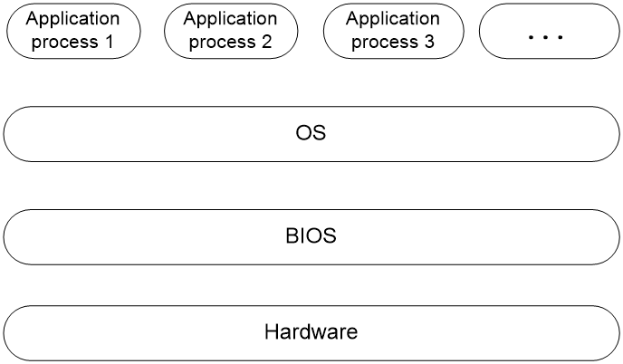
The Basic Input and Output System (BIOS) is a non-volatile firmware stored in the system ROM of a server. It is used to perform hardware initialization during server booting and provide runtime services for the operating systems. As shown in Figure 1, the BIOS interacts between the server hardware and the operating system (OS).
The main functions of BIOS include:
· Performing POST self-test.
· Detecting input and output devices and bootable devices, including memory initialization, hardware scanning, finding boot devices, and starting the system.
· Providing advanced power management ACPI.
· Configuring RAID.
Figure 1 Layered architecture of a server system
Applicable products
This document is applicable to the following products:
· H3C UniServer R3950 G6
· H3C UniServer R4950 G6
· H3C UniServer R5350 G6
· H3C UniServer R5500 G6 AMD
Applicable versions
The BIOS version applicable to this article is BIOS-6.30.XX.
Using this document
The information in this document is subject to change over time.
The information in this document might differ from your product if it contains custom configuration options or features.
BIOS Recommended Configuration
Introduction
Configuration template is a collection of configuration options that deploys BIOS settings to suit the expected application of the server. BIOS provides multiple sets of configuration templates to help users deploy the most suitable BIOS settings according to different scenarios. The configuration parameters in the templates are suggested values for various application scenarios.
Recommended BIOS parameter configurations for various workload modes
The recommended BIOS parameter configurations for various workload patterns are shown in Table 1, Table 2, Table 3, and Table 4, illustrating the dependencies associated with scenario configuration templates. X indicates no requirement for that option in the configuration template and defaults to the default value of the current model. The meaning of X might vary among different models. When applying a configuration template, X values in the template will be restored to the default values of the current model.
|
|
IMPORTANT: · Not all options corresponding to the table are displayed in BIOS, but when using the configuration template, the corresponding option settings will default to the values shown in the table. · Selecting a configuration template other than Custom will gray out the relevant options in the template, making them unmodifiable. Modifying associated options using the out-of-band Redfish and in-band SCE tools will also not take effect. |
For applicable scenarios and configuration explanations of various workload mdoes, see Introduction to workload mode.
Table 1 General-Purpose Workloads and configuration template dependencies
|
Dependencies |
CPU intensive |
Java throughput intensive |
Java latency sensitive |
Power efficiency |
|
SMT Control |
Enabled |
Enabled |
Enabled |
Enabled |
|
L1 Stream HW Prefetcher |
Enabled |
Enabled |
Enabled |
Enabled |
|
L1 Stride Prefetcher |
Enabled |
Enabled |
Enabled |
Enabled |
|
L1 Region Prefetcher |
Enabled |
Enabled |
Enabled |
Enabled |
|
L1 Burst Prefetch Mode |
Enabled |
Enabled |
Enabled |
Enabled |
|
L2 Stream HW Prefetcher |
Enabled |
Enabled |
Enabled |
Enabled |
|
L2 Up/Down Prefetcher |
Enabled |
Enabled |
Enabled |
Enabled |
|
BoostFmaxEn |
Auto |
Auto |
Auto |
Auto |
|
Power Profile Selection |
High Performance Mode |
High Performance Mode |
High Performance Mode |
Efficiency Mode |
|
Determinism Control |
Auto |
Auto |
Auto |
Auto |
|
Determinism Enable |
X |
X |
X |
X |
|
TDP Control |
Manual |
Manual |
Manual |
Manual |
|
TDP |
OPN Max |
OPN Max |
OPN Max |
OPN Max |
|
PPT Control |
Manual |
Manual |
Manual |
Manual |
|
PPT |
OPN Max |
OPN Max |
OPN Max |
OPN Max |
|
CPPC |
Auto |
Auto |
Auto |
Auto |
|
ACPI SRAT L3 Cache As NUMA Domain |
Disabled |
Disabled |
Disabled |
Enable |
|
NUMA Nodes per Socket |
NPS1 |
NPS4 |
NPS2 |
NPS4 |
|
Memory Target Speed |
DDR4800 |
DDR4800 |
DDR4800 |
DDR4800 |
|
Memory Interleaving |
Enabled |
Enabled |
Enabled |
Enabled |
|
3-link xGMI max speed |
32Gbps |
32Gbps |
32Gbps |
32Gbps |
|
4-link xGMI max speed |
32Gbps |
32Gbps |
32Gbps |
32Gbps |
|
xGMI Link Width Control |
Auto |
Auto |
Auto |
Auto |
|
xGMI Max Link Width |
X |
X |
X |
X |
|
xGMI Max Link Width Control |
X |
X |
X |
X |
|
xGMI Force Link Width Control |
X |
X |
X |
X |
|
xGMI Force Link Width |
X |
X |
X |
X |
|
APBDIS |
0 |
0 |
0 |
1 |
|
DF Cstates |
Disabled |
Disabled |
Disabled |
Disabled |
|
Local APIC Mode |
Auto |
Auto |
Auto |
Auto |
|
PCIE Speed PMM Control |
Auto |
Auto |
Auto |
Auto |
|
SRIOV |
Disabled |
Disabled |
Disabled |
Disabled |
|
PCIe Ten Bit Tag Support |
Enabled |
Enabled |
Enabled |
Enabled |
|
IOMMU |
Enabled |
Enabled |
Enabled |
Enabled |
|
TSME |
Auto |
Auto |
Auto |
Auto |
|
Note: The OPN Max values of TDP and PPT options are related to the CPU model. For more information about the OPN Max value, see Table 5. |
||||
Table 2 Memory and I/O Intensive Workloads and configuration template dependencies
|
Dependencies |
Memory throughput intensive |
Storage I/O intensive |
NIC throughput intensive |
NIC latency sensitive |
|
SMT Control |
Enabled |
Enabled |
Disabled |
Disabled |
|
L1 Stream HW Prefetcher |
Enabled |
Enabled |
Enabled |
Enabled |
|
L1 Stride Prefetcher |
Enabled |
Enabled |
Enabled |
Enabled |
|
L1 Region Prefetcher |
Enabled |
Enabled |
Enabled |
Enabled |
|
L1 Burst Prefetch Mode |
Enabled |
Enabled |
Enabled |
Enabled |
|
L2 Stream HW Prefetcher |
Enabled |
Enabled |
Enabled |
Enabled |
|
L2 Up/Down Prefetcher |
Enabled |
Enabled |
Enabled |
Enabled |
|
BoostFmaxEn |
Auto |
Auto |
Auto |
Auto |
|
Power Profile Selection |
High Performance Mode |
High Performance Mode |
High Performance Mode |
High Performance Mode |
|
Determinism Control |
Auto |
Manual |
Manual |
Manual |
|
Determinism Enable |
X |
Power |
Performance |
Performance |
|
TDP Control |
Manual |
Auto |
Auto |
Auto |
|
TDP |
OPN Max |
X |
X |
X |
|
PPT Control |
Manual |
Auto |
Auto |
Auto |
|
PPT |
OPN Max |
X |
X |
X |
|
CPPC |
Auto |
Auto |
Auto |
Auto |
|
ACPI SRAT L3 Cache As NUMA Domain |
Enabled |
Disabled |
Disabled |
Disabled |
|
NUMA Nodes per Socket |
NPS1 |
NPS1 |
NPS1 |
NPS1 |
|
Memory Target Speed |
DDR4800 |
DDR4800 |
DDR4800 |
DDR4800 |
|
Memory Interleaving |
Enabled |
Enabled |
Enabled |
Enabled |
|
3-link xGMI max speed |
32Gbps |
32Gbps |
32Gbps |
32Gbps |
|
4-link xGMI max speed |
32Gbps |
32Gbps |
32Gbps |
32Gbps |
|
xGMI Link Width Control |
Auto |
Auto |
Auto |
Manual |
|
xGMI Max Link Width |
X |
X |
X |
2 |
|
xGMI Max Link Width Control |
X |
X |
X |
Manual |
|
xGMI Force Link Width Control |
X |
X |
X |
Unforce |
|
xGMI Force Link Width |
X |
X |
X |
X |
|
APBDIS |
0 |
1 |
0 |
0 |
|
DF Cstates |
Disabled |
Disabled |
Disabled |
Disabled |
|
Local APIC Mode |
Auto |
Auto |
Auto |
Auto |
|
PCIE Speed PMM Control |
Auto |
Static Target Link Speed (GEN5) |
Static Target Link Speed (GEN5) |
Static Target Link Speed (GEN5) |
|
SRIOV |
Disabled |
Disabled |
Disabled |
Disabled |
|
PCIe Ten Bit Tag Support |
Enabled |
Enabled |
Enabled |
Enabled |
|
IOMMU |
Enabled |
Enabled |
Enabled |
Enabled |
|
TSME |
Auto |
Auto |
Auto |
Auto |
|
Note: The OPN Max values of TDP and PPT options are related to the CPU model. For more information about the OPN Max value, see Table 5. |
||||
Table 3 Database and Analytics and configuration template dependencies
|
Dependencies |
RDBMS optimized |
Big data analytics optimized |
AI optimized |
IOT gateway |
|
SMT Control |
Enabled |
Enabled |
Enabled |
Enabled |
|
L1 Stream HW Prefetcher |
Enabled |
Enabled |
Auto |
Enabled |
|
L1 Stride Prefetcher |
Enabled |
Enabled |
Auto |
Enabled |
|
L1 Region Prefetcher |
Enabled |
Enabled |
Auto |
Enabled |
|
L1 Burst Prefetch Mode |
Enabled |
Enabled |
Auto |
Enabled |
|
L2 Stream HW Prefetcher |
Enabled |
Enabled |
Auto |
Enabled |
|
L2 Up/Down Prefetcher |
Enabled |
Enabled |
Auto |
Enabled |
|
BoostFmaxEn |
Auto |
Auto |
Auto |
Auto |
|
Power Profile Selection |
Maximum IO Performance Mode |
High Performance Mode |
High Performance Mode |
High Performance Mode |
|
Determinism Control |
Manual |
Auto |
Manual |
Auto |
|
Determinism Enable |
Power |
X |
Performance |
X |
|
TDP Control |
Manual |
Auto |
Auto |
Auto |
|
TDP |
OPN Max |
X |
X |
X |
|
PPT Control |
Manual |
Auto |
Auto |
Auto |
|
PPT |
OPN Max |
X |
X |
X |
|
CPPC |
Auto |
Auto |
Auto |
Auto |
|
ACPI SRAT L3 Cache As NUMA Domain |
Disabled |
Disabled |
Auto |
Disabled |
|
NUMA Nodes per Socket |
NPS1 |
NPS1 |
Auto |
NPS1 |
|
Memory Target Speed |
DDR4800 |
DDR4800 |
Auto |
DDR4800 |
|
Memory Interleaving |
Enabled |
Enabled |
Auto |
Enabled |
|
3-link xGMI max speed |
32Gbps |
32Gbps |
Auto |
32Gbps |
|
4-link xGMI max speed |
32Gbps |
32Gbps |
Auto |
32Gbps |
|
xGMI Link Width Control |
Auto |
Auto |
Auto |
Auto |
|
xGMI Max Link Width |
X |
X |
X |
X |
|
xGMI Max Link Width Control |
X |
X |
X |
X |
|
xGMI Force Link Width Control |
X |
X |
X |
X |
|
xGMI Force Link Width |
X |
X |
X |
X |
|
APBDIS |
1 |
0 |
Auto |
0 |
|
DF Cstates |
Disabled |
Disabled |
Disabled |
Disabled |
|
Local APIC Mode |
Auto |
Auto |
Auto |
Auto |
|
PCIE Speed PMM Control |
Auto |
Auto |
Auto |
Auto |
|
SRIOV |
Disabled |
Disabled |
Auto |
Disabled |
|
PCIe Ten Bit Tag Support |
Enabled |
Enabled |
Auto |
Enabled |
|
IOMMU |
Enabled |
Enabled |
Auto |
Enabled |
|
TSME |
Auto |
Auto |
Auto |
Auto |
|
Global C-state Control |
N/A |
N/A |
Disabled |
N/A |
|
Note: The OPN Max values of TDP and PPT options are related to the CPU model. For more information about the OPN Max value, see Table 5. |
||||
Table 4 HPC and Telco settings
|
Dependencies |
HPC optimized |
OpenStack NFV |
OpenStack for realtime Kernel |
|
SMT Control |
Disabled |
Enabled |
Enabled |
|
L1 Stream HW Prefetcher |
Enabled |
Enabled |
Enabled |
|
L1 Stride Prefetcher |
Enabled |
Enabled |
Enabled |
|
L1 Region Prefetcher |
Enabled |
Enabled |
Enabled |
|
L1 Burst Prefetch Mode |
Enabled |
Enabled |
Enabled |
|
L2 Stream HW Prefetcher |
Enabled |
Enabled |
Enabled |
|
L2 Up/Down Prefetcher |
Enabled |
Enabled |
Enabled |
|
BoostFmaxEn |
Auto |
Auto |
Auto |
|
Power Profile Selection |
High Performance Mode |
High Performance Mode |
High Performance Mode |
|
Determinism Control |
Manual |
Manual |
Manual |
|
Determinism Enable |
Performance |
Performance |
Performance |
|
TDP Control |
Manual |
Auto |
Auto |
|
TDP |
OPN Max |
X |
X |
|
PPT Control |
Manual |
Auto |
Auto |
|
PPT |
OPN Max |
X |
X |
|
CPPC |
Auto |
Auto |
Auto |
|
ACPI SRAT L3 Cache As NUMA Domain |
Disabled |
Disabled |
Disabled |
|
NUMA Nodes per Socket |
NPS4 |
NPS1 |
NPS1 |
|
Memory Target Speed |
DDR4800 |
DDR4800 |
DDR4800 |
|
Memory Interleaving |
Enabled |
Enabled |
Enabled |
|
3-link xGMI max speed |
32Gbps |
32Gbps |
32Gbps |
|
4-link xGMI max speed |
32Gbps |
32Gbps |
32Gbps |
|
xGMI Link Width Control |
Auto |
Auto |
Auto |
|
xGMI Max Link Width |
X |
X |
X |
|
xGMI Max Link Width Control |
X |
X |
X |
|
xGMI Force Link Width Control |
X |
X |
X |
|
xGMI Force Link Width |
X |
X |
X |
|
APBDIS |
0 |
0 |
0 |
|
DF Cstates |
Disabled |
Disabled |
Disabled |
|
Local APIC Mode |
Auto |
Auto |
Auto |
|
PCIE Speed PMM Control |
Auto |
Auto |
Auto |
|
SRIOV |
Disabled |
Disabled |
Disabled |
|
PCIe Ten Bit Tag Support |
Enabled |
Enabled |
Enabled |
|
IOMMU |
Enable |
Enabled |
Enabled |
|
TSME |
Auto |
Auto |
Auto |
|
Note: The OPN Max value of TDP and PPT options is related to the CPU model. For more information about the OPN Max value, see Table 5. |
|||
Table 5 OPN MAX comparison table
|
CPU model |
TDP value |
PPT value |
|
9654 |
400 |
400 |
|
9634 |
300 |
300 |
|
9554 |
400 |
400 |
|
9534 |
300 |
300 |
|
9474 |
400 |
400 |
|
9454 |
300 |
300 |
|
9374 |
400 |
400 |
|
9354 |
300 |
300 |
|
9334 |
240 |
240 |
|
9274 |
400 |
400 |
|
9254 |
240 |
240 |
|
9224 |
240 |
240 |
|
9174 |
400 |
400 |
|
9124 |
240 |
240 |
Introduction to workload mode
This chapter introduces the applicable scenarios and configuration instructions for each workload mode.
|
|
IMPORTANT: In this document, the BIOS configuration solutions in different scenarios are general solutions. For special needs, configure it as needed. |
BIOS provides the following configuration templates.
CPU intensive
CPU intensive mode is applicable to scenarios that require a large amount of processor computational power. Scientific calculations, graphics processing, and game servers all require high CPU performance. As a best practice, use a multi-core CPU with high-speed cache and high-performance memory to improve processing efficiency.
Java throughput intensive
Java throughput intensive mode is applicable to Java applications that require high throughput data processing. Common scenarios include web services, large-scale data processing, and multimedia processing. It typically involves handling numerous requests and completing complex computations or data processing tasks.
Java latency sensitive
Java latency sensitive mode is applicable to Java applications that require quick and accurate response to requests. It requires low-latency storage and network transmission mechanisms to support real-time use cases. It is commonly used in real-time data analysis, online gaming, healthcare, and other fields.
Power efficiency
Power efficiency mode is applicable to scenarios such as data centers, cloud computing, virtualization, and high-performance computing. Its main goal is to provide higher energy efficiency. It involves considering actual needs and hardware devices to maximize server energy efficiency.
Memory throughput intensive
Memory throughput intensive mode is applicable to scenarios that require high memory throughput. These scenarios involve extensive memory operations and data processing.
Common use cases include large-scale data processing, real-time data processing, and streaming and large-scale distributed systems. They require high-performance and high memory throughput hardware, as well as considerations for software architecture and technology.
Storage I/O intensive
Storage I/O intensive mode is applicable to scenarios that involve a large volume of data read and write operations. Common use cases include databases, video processing, and big data analytics. It requires efficient I/O systems to ensure high efficiency and accuracy in data processing.
NIC throughput intensive
NIC throughput intensive mode is applicable to scenarios that require high NIC throughput. These scenarios typically involve handling a large number of I/O operations, concurrent operations, and network operations.
Common use cases include data centers, large-scale cloud service providers, and video streaming, which require high-speed and high-throughput network cards to ensure fast data transmission and efficient network operations.
NIC latency sensitive
NIC latency sensitive mode is applicable to scenarios that have high requirements for network latency/response time. For example, real-time video content delivery, high-frequency trading systems, and online gaming, which require a quick response to requests within a very short time. Any delay in these scenarios can have a negative impact on the system.
RDBMS optimized
Relational Database Management Systems (RDBMS) are often a critical component of data centers. Efficient RDBMS services are crucial for organizations handling massive data like large enterprises, financial institutions, and healthcare facilities. RDBMS optimization improves server configuration to enhance system performance and reliability in these scenarios.
Big data analytics optimized
The application of big data analytics optimized mode requires meeting the demands of data storage, data processing, data visualization, and other aspects. By appropriately adjusting server parameters in line with the characteristics of this scenario, performance improvements can be achieved in the aspect of Big Data analytics processing.
IOT gateway
IoT gateway is a crucial component of the IoT architecture, commonly used for data exchange, data collection, data processing, and more between IoT devices and cloud platforms.
HPC optimized
HPC Optimized is a mode that is optimized for high-performance computing (HPC) applications. HPC is commonly used in scenarios involving intensive computations, such as handling multiple concurrent tasks. As a best practice, enable hyper-threading technology for better CPU performance in this HPC scenario.
OpenStack NFV
OpenStack NFV provides higher scalability, flexibility, security and integration for telecom networks. It virtualizes network functions using virtualization and cloud computing technologies, providing operators with an advanced network management tool to meet evolving market demands.
OpenStack for realtime kernel
OpenStack for realtime kernel mode uses real-time kernel to make applications on OpenStack more real-time. This helps applications to quickly respond and process real-time data, thereby improving system performance and usability. Additionally, real-time kernel ensures a higher quality application experience.
AI Optimized
The AI Optimized mode is used for application scenarios that perform artificial intelligence inference or training on large-scale computational resources to meet performance requirements.
Similar to the high performance computing template, this mode boosts server performance in scenarios involving artificial intelligence inference or training by locking the CPU to its highest performance level.
Custom
Custom mode utilizes the default BIOS settings or the values of the most recent configuration template. Users can customize various parameters based on this template. For specific description of each option, see the user guide for the default BIOS settings.
Configure the template
The options for the scenario configuration template is called Workload Profile Configuration and can be found on the Miscellaneous Configuration tab within the Advanced page. The specific steps for configuring this option are described below.
Access to the BIOS Setup page
1. Connect the keyboard, mouse, and monitor to the server, or access the remote console through the HDM web interface. For more information about detailed instructions on launching the remote console, see HDM user guide.
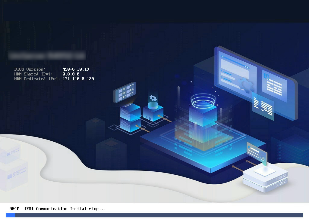
2. Start or restart the server. Once you access to the BIOS startup interface, press Del or Esc.
Figure 2 Starting BIOS
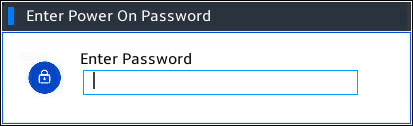
3. Enter the startup password in the dialog box that opens.
Figure 3 Entering the startup password
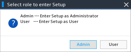
4. If a BIOS administrator and user password is set, you can select the login role first when entering the BIOS Setup page. Only the BIOS administrator role can configure BIOS.
Figure 4 Selecting the login role
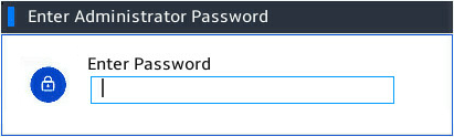
5. Enter the password corresponding to the selected role.
Figure 5 Entering the password
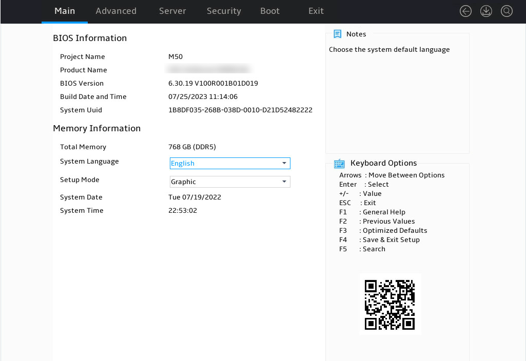
6. Enter the BIOS Setup page.
Figure 6 Entering the BIOS Setup page
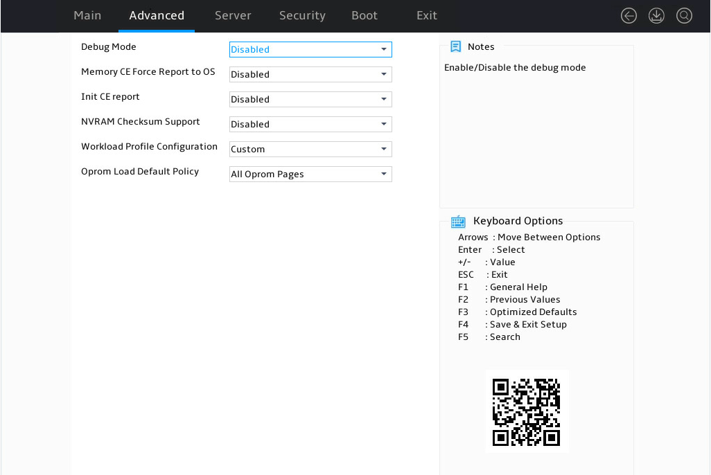
Access to the Miscellaneous Configuration page
Click Miscellaneous Configuratio under the Advanced tab, and click Enter.
Figure 7 Miscellaneous Configuration
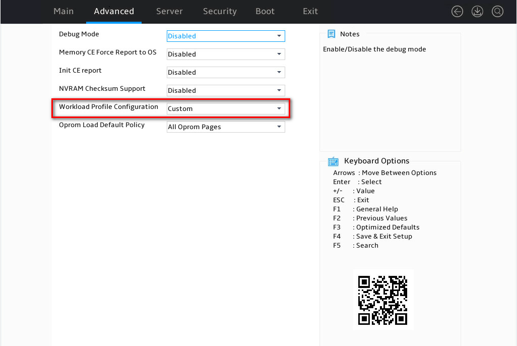
Selet a configuration template
Click the drop-down box and select a required workload configuration template as needed.
Figure 8 Selecting a configuration template
Restart to take effect
After you complete the settings, press F4. Click OK in the dialog box that opens, and save the settings and exit the BIOS interface. The settings will take effect after you restart the server.
